Loading ...
Loading ...
Loading ...
OPERATION
_ WARNING: To reduce the risk of
injury, turn unff off and disconnect
it from power source before
making any adjustments or
removing/installing attachments or
accessories. An accidental start-up
can cause injury.
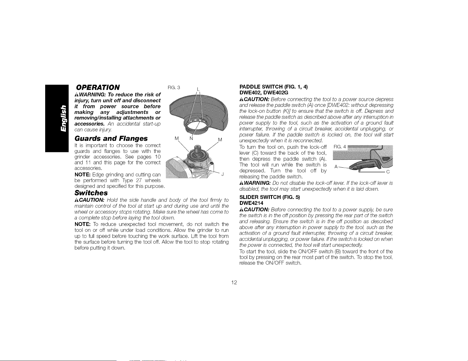
Guards and Flanges
It is important to choose the correct
guards and flanges to use with the
grinder accessories. See pages 10
and 11 and this page for the correct
accessories.
NOTE: Edge grinding and cutting can
be performed with Type 27 wheels
designed and specified for this purpose.
Switches
FIG. 3 L
M N M
_CAUTION: Hold the side handle and body of the tool firmly to
maintain control of the tool at start up and during use and until the
wheel or accessory stops rotating. Make sure the wheel has come to
a complete stop before laying the tool down.
NOTE: To reduce unexpected tool movement, do not switch the
tool on or off while under load conditions. Allow the grinder to run
up to full speed before touching the work surface. Lift the tool from
the surface before turning the tool off. Allow the tool to stop rotating
before putting it down.
PADDLE SWITCH (FIG. 1, 4)
DWE402, DWE402G
J_CAUTION: Before connecting the tool to a power source depress
and release the paddle switch (A) once [DWE402: without depressing
the lock-on button (K)] to ensure that the switch is off. Depress and
release the paddle switch as described above after any interruption in
power supply to the tool, such as the activation of a ground fault
interrupter, throwing of a circuit breaker, accidental unplugging, or
power failure. If the paddle switch is locked on, the tool will start
unexpectedly when it is reconnected.
To turn the tool on, push the lock-off FIG.4
lever (C) toward the back of the tool,
then depress the paddle switch (A).
The tool will run while the switch is
depressed. Turn the tool off by O
releasing the paddle switch.
_WARNING: Do not disable the lock-off lever. If the lock-off lever is
disabled, the tool may start unexpectedly when it is laid down.
SLIDER SWITCH (FIG. 5}
DWE4214
_CAUTION: Before connecting the tool to a power supply, be sure
the switch is in the off position by pressing the rear part of the switch
and releasing. Ensure the switch is in the off position as described
above after any interruption in power supply to the tool, such as the
activation of a ground fault interrupter, throwing of a circuit breaker,
accidental unplugging, or power failure. If the switch is locked on when
the power is connected, the tool will start unexpectedly.
To start the tool, slide the ON/OFF switch (B) toward the front of the
tool by pressing on the rear most part of the switch. To stop the tool,
release the ON/OFF switch.
12
Loading ...
Loading ...
Loading ...