Loading ...
Loading ...
Loading ...
Replacement Parts
IMPORTANT: The following maintenance procedures are
for the Flame Lock®Safety System components and should
be performed by a qualified person.
Replacement parts may be ordered through your plumber
or the local distributor. Parts will be shipped at prevailing
prices and billed accordingly. When ordering replacement
parts, always have the following information ready:
1. model, serial, and product number
2. type of gas
3. item number
4. parts description
See pages 30-31 for a list of available repair parts.
Removing the Manifold Assembly
1. Turn off the gas to the water heater at the manual
shut-off valve (Figure 3).
2. Turn the gas control/temperature knob to the "OFF"
,
4.
,
position (Figure 19A).
Remove the outer door.
Remove the two screws
(1/4" nut driver) securing
the manifold door assembly
to the combustion chamber
(Figure 23).
Disconnect the pilot tube
(7/16" wrench), the igniter
wire from the igniter lead
wire, and manifold tube
(3/4" wrench) at the gas
control valve/thermostat.
Also use needle nose pliers
to disconnect the red (+)
and white (-) thermopile
Figure 22
Gas Control Valve/
Thermostat
o
Ignite
Butto S _'_'_'_'_'_'_'_'_'_' ' White
_! _ _ Wire
Ignit_ _ _ q_ !_/i (R.ig,ht
_ead I1 _ _ _\_ bl.ae)
UJPilot i \
.,!i Tube ) Red
7_ / Wire
!g.niter Manifold (Left
wire Tube Side 1
wires from the gas control valve/thermostat. See
Figures 22 & 23. NOTE: L.P. Gas systems use
reverse (left-hand) threads on the manifold tube.
6. Grasp the manifold tube and push down slightly to free
the manifold, pilot tube, and thermopile.
7. Carefully remove the manifold assembly from the
burner compartment.
NOTE: Be sure not to damage internal parts.
Figure 23
Burner Assembly
Removal
Gas Control Valve/Thermostat Thermopile and
Switch Wire
Connections
Piezo Igniter
Pilot Tube_ Vlanifold Tube
Switch
Outer Door]
Not ShownJ
Manifold Screw (2)--
.Manifold Door
Manifold Component Block
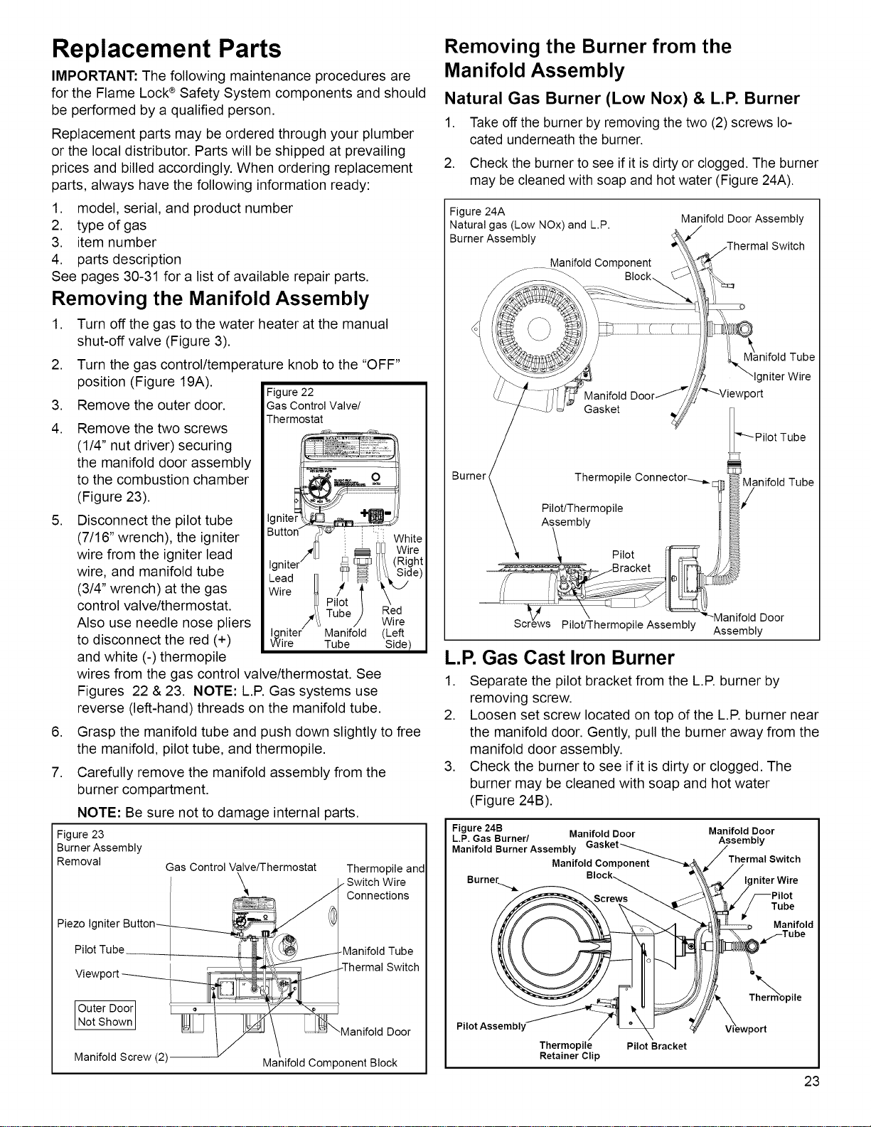
Removing the Burner from the
Manifold Assembly
Natural Gas Burner (Low Nox) & L.P. Burner
1. Take off the burner by removing the two (2) screws lo-
cated underneath the burner.
2. Check the burner to see if it is dirty or clogged. The burner
may be cleaned with soap and hot water (Figure 24A).
Figure 24A
Natural gas (Low NOx) and L.P.
Burner Assembly
Manifold Component
_---_ Block_
Manifold Door Assembly
Switch
anifold Tube
Manifold
Gasket
_Pilot Tube
Therm°pile C°n nect°r"---_ 1 ] _/anifold Tube
Pilot/Thermopile
Assembly
\ P,ot \
................-:-- oo o o_,_ jBracket III qlPlt A /
_ . Manifold Door
screws Hiot/Thermopi e Assembly Assembly
L.R Gas Cast Iron Burner
1. Separate the pilot bracket from the L.P. burner by
removing screw.
2. Loosen set screw located on top of the L.P. burner near
the manifold door. Gently, pull the burner away from the
manifold door assembly.
3. Check the burner to see if it is dirty or clogged. The
burner may be cleaned with soap and hot water
(Figure 24B).
Figure 24B Manifold Door Manifold Door
L.P. Gas Burner/ Assembly
Manifold Burner Assembly Gasket_ /
Thermal Switch
Manifold Component -""--_/ /
Burner......._ Block__ "_, _/ Igniter Wire
Screws _ _ j_\\_. //_Pilot
-% / Tube
. A _ _'--_ Manifold
y Thermopile
Pilot Assembly
Thermopile Pilot Bracket
Retainer Clip
23
Loading ...
Loading ...
Loading ...