Loading ...
Loading ...
Loading ...
9
FINAL INSTALLATION
DANGER: To reduce the risk of serious bodily
injury, DO NOT use power tools to assemble the
blades (E). If screws are overtightened, blades (E)
may crack and break.
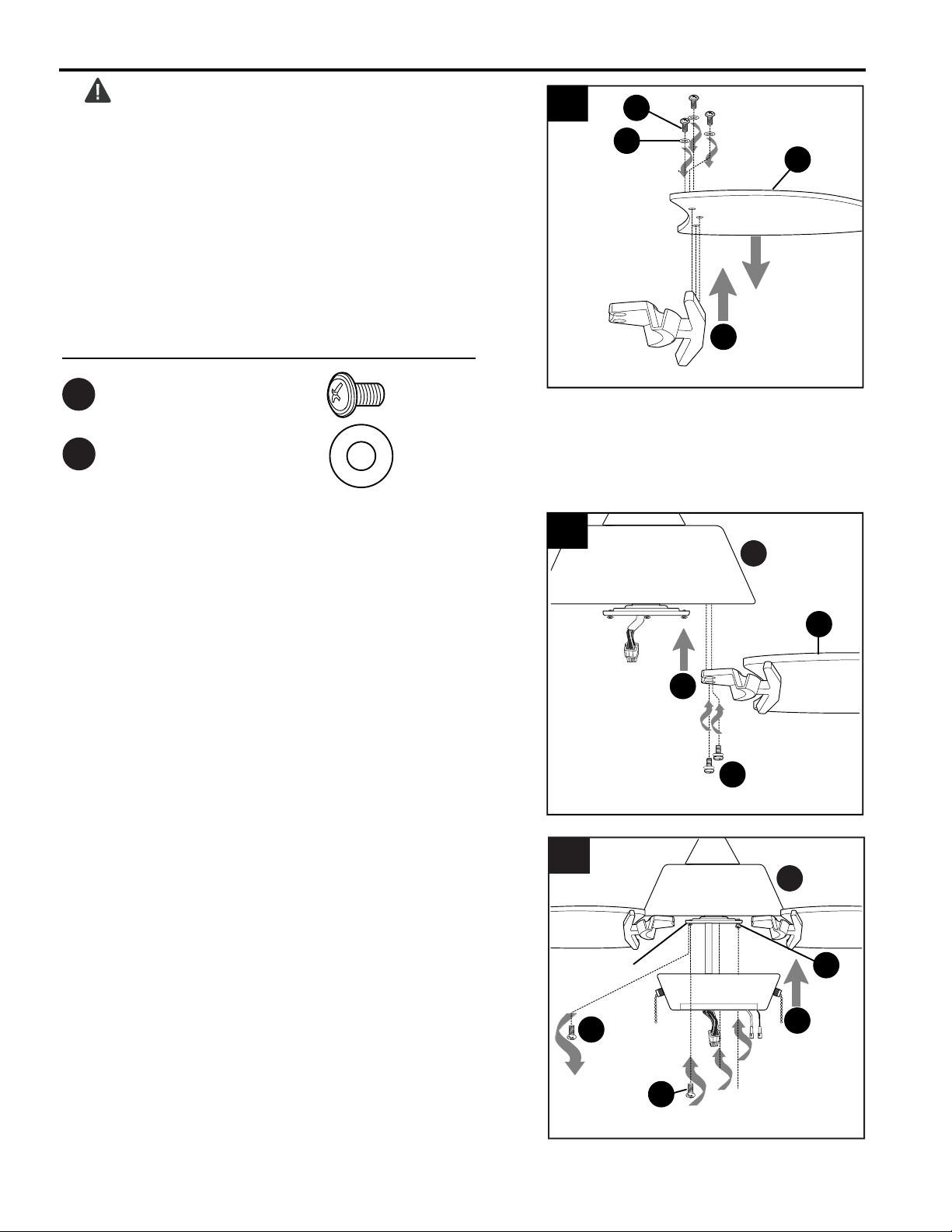
Partially insert three blade screws (AA) along with
three rubber blade washers (BB) into holes in blade
(E) (labeled THIS SIDE UP) to attach blade arm (J) to
blade (E). Then, tighten each blade screw (AA)
starting with the one in the middle.
Repeat Step 2 for remaining blades (E) and blade
arms (J).
1.
Rubber Blade Washer x 18
BB
Hardware Used
1
BB
AA
E
J
AA
Blade Screw x 18
B
2
E
J
Attach blade arms (J) to the bottom of motor housing
(B) with motor screws/lock washers (M) previously
removed (Step 1, page 6). Tighten motor screws/lock
washers (M) securely.
NOTE: Make sure to completely secure each blade
arm (J) before proceeding to the next.
2.
M
3.
Remove one motor plate screw (L) from motor
plate preassembled on the underside of the motor
housing (B) and partially loosen the other two
motor plate screws (L). Align slotted holes in
switch housing (F) with loosened motor plate
screws (L), allowing molex connections from
motor housing (B) to come through hole in switch
housing (F). Twist switch housing (F) to lock.
Re-insert the motor plate screw (L) that was
removed and securely tighten all three motor plate
screws (L).
3
I
L
I
L
I
L
F
B
Motor
Plate
Loading ...
Loading ...
Loading ...