Loading ...
Loading ...
Loading ...
Supply Air Flow Data
Indoor CFM & External Static Pressure
Indoor air ow may be determined by measuring the
external static pressure (ESP) of the duct system using an
inclined manometer or magnahelic gauge and consulting
the above chart to derive actual air ow. Under no
circumstances should the small chassis VTAC equipment
be operated at an external static pressure in excess of .3”
W.C. Operation of the VTAC under these conditions will
result in inadequate air ow, leading to poor performance
and/or premature component failure.
Control
For LOW speed only operation, connect the fan output
terminal from the thermostat to the GL terminal of the
electronic control.
For HIGH speed only operation, connect the fan output
terminal from the thermostat to the GH terminal of the
electronic control.
For thermostats with two-speed capability, connect the
LOW speed output to the GL terminal and the HIGH speed
output to the GH terminal.
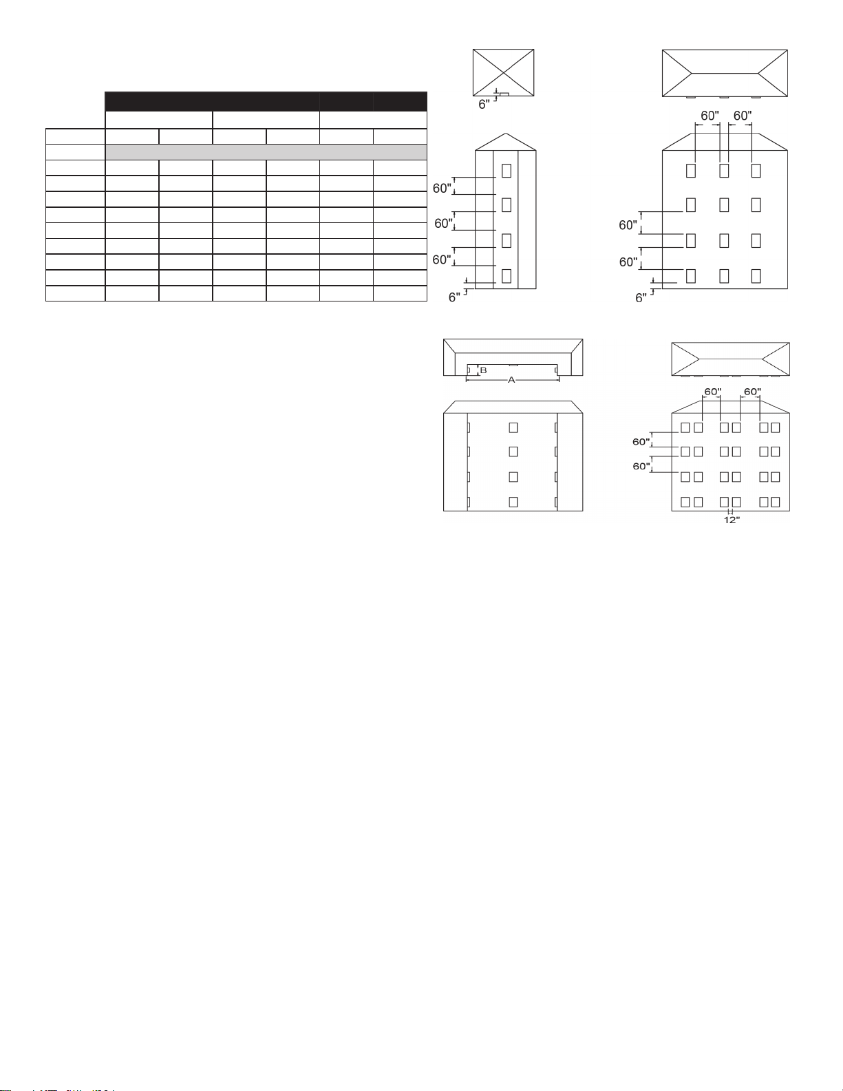
VTAC Required Minimum Clearances
Building Exterior Unit Opening Requirements
VTAC units must be installed on an outside wall. Conned
spaces and/or covered areas should be avoided. Units
must be installed no closer than 12” apart when two units
are side by side. If three or more units are to operate next
to one another, maintain a minimum of 60” between units or
pairs of units (Figure B). If more than two units are sharing
a oor with adjacent, outset units, a minimum distance of
64” must be kept between units (Figure C). Also, a vertical
clearance of 60” must be maintained (Figure A) between
units. Units installed on the bottom oor must be mounted
at least 6” off of the ground.
Figure A Figure B
Figure C Figure D
Grill Clearance Requirements
Where obstructions are present use the following
guidelines for proper spacing from the VTAC exterior
louvered grill. Amana recommends that ALL obstructions
are a minimum of 72” from the exhaust.
For minor obstruction(s) such as lamp poles or small
shrubbery, a clearance of 24” from the outdoor louver must
be maintained.
For major obstructions such as a solid fence, wall, or other
heat rejecting devices like a condensing unit, a minimum
distance of 72” must be kept.
3
Model
AVH09/AVH12 AVH18 AVH24
Fan Speed Low
High
L
ow
High
Low
High
ESP (“)
SCFM
0.0” 470
520 730 800 755 805
0.05”
460
510 670 735 700 750
0.10”
430
490 630 675 660 700
0.15”
410 470 595 640 615 665
0.20”
360 440 550 600 575 625
0.25”
310
400 505 550 525 580
0.30”
260 350 455 500 485 540
0.35”
-- -- 400 445 450 500
0.40”
-- -- 345 400 415 465
Loading ...
Loading ...
Loading ...