Loading ...
Loading ...
Loading ...
Primary Drain Connection and Location
For AVH09 & AVH12 Units only
NOTE: Failure to follow the following procedures may
result in serious property damage. A field supplied
secondary condensate pan or P-trap may be required.
Check with local codes. In case of drainage system
blockage, the unit base will allow excess water to flow
out of the unit through the wall adapter and the
architectural louver. It is critical to ensure that the
drainage path is not blocked or obstructed in any way
during the installation.
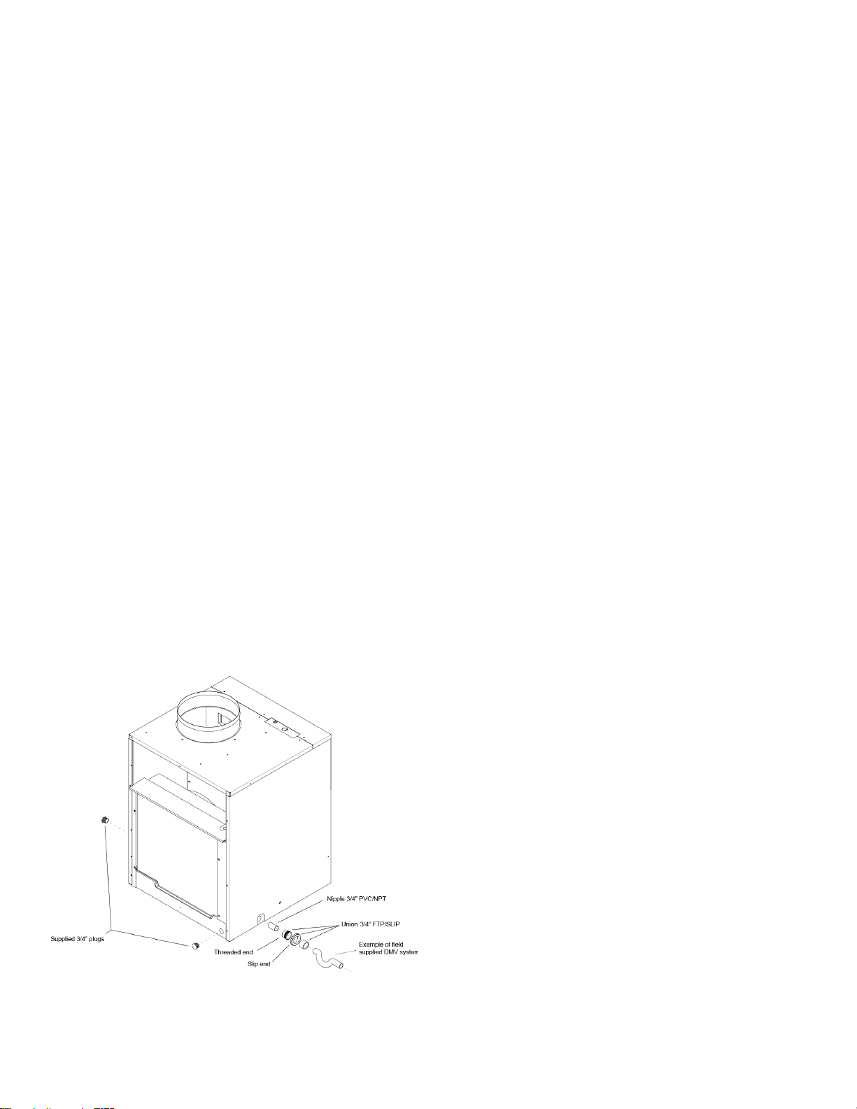
1. The supplied drain kit must be connected to one of
the three (left, right or rear) 3/4” FPT connections
on the unit base pan. Use of rear fitting without
connection to DWV system (drain, waste, vent)
may result in staining of the outside wall.
2. Insert the provided 3/4” nipple into the determined
connection using eld-supplied Teon tape or pipe
joint compound.
3. With the slip end of a 3/4” union, connect to the
nipple with Teon tape or pipe joint compound.
4. Hand-tighten all ttings to prevent damage to unit or
ttings.
5. Install a eld-supplied drain system to the slip end
of the union. A trap is recommended and drain
connections should be connected to building DWV
system. Pitch the drain line of a 1/4” downward slope
for every foot (1’) of lateral horizontal run to the
DWV.
6. Plug the two unused connection ports with the two
provided 3/4” pipe plugs with eld-supplied Teon
tape or pipe joint compound. Hand tighten to prevent
damage to the unit or ttings. Do not thread metal or
copper pipe ttings directly into unit.
7. Check the system for leaks.
10
Loading ...
Loading ...
Loading ...