Loading ...
Loading ...
Loading ...
Test the Installation
6
Step 3 - Convert Valves for LP Gas
The bypass jet on each valve must be adjusted. Your
cooktop may come with either hollow or solid valve shafts.
Determine the bypass screw location accordingly.
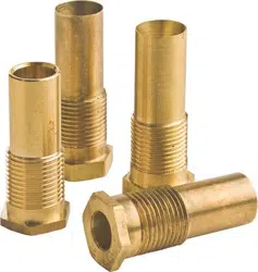
1. Turn all knobs to the “Off” position.
2. Remove knobs.
Your appliance will have either a) hollow stem valves, or b)
solid stem valves. The location of the adjustment screw is
determined by which type of valve your appliance has.
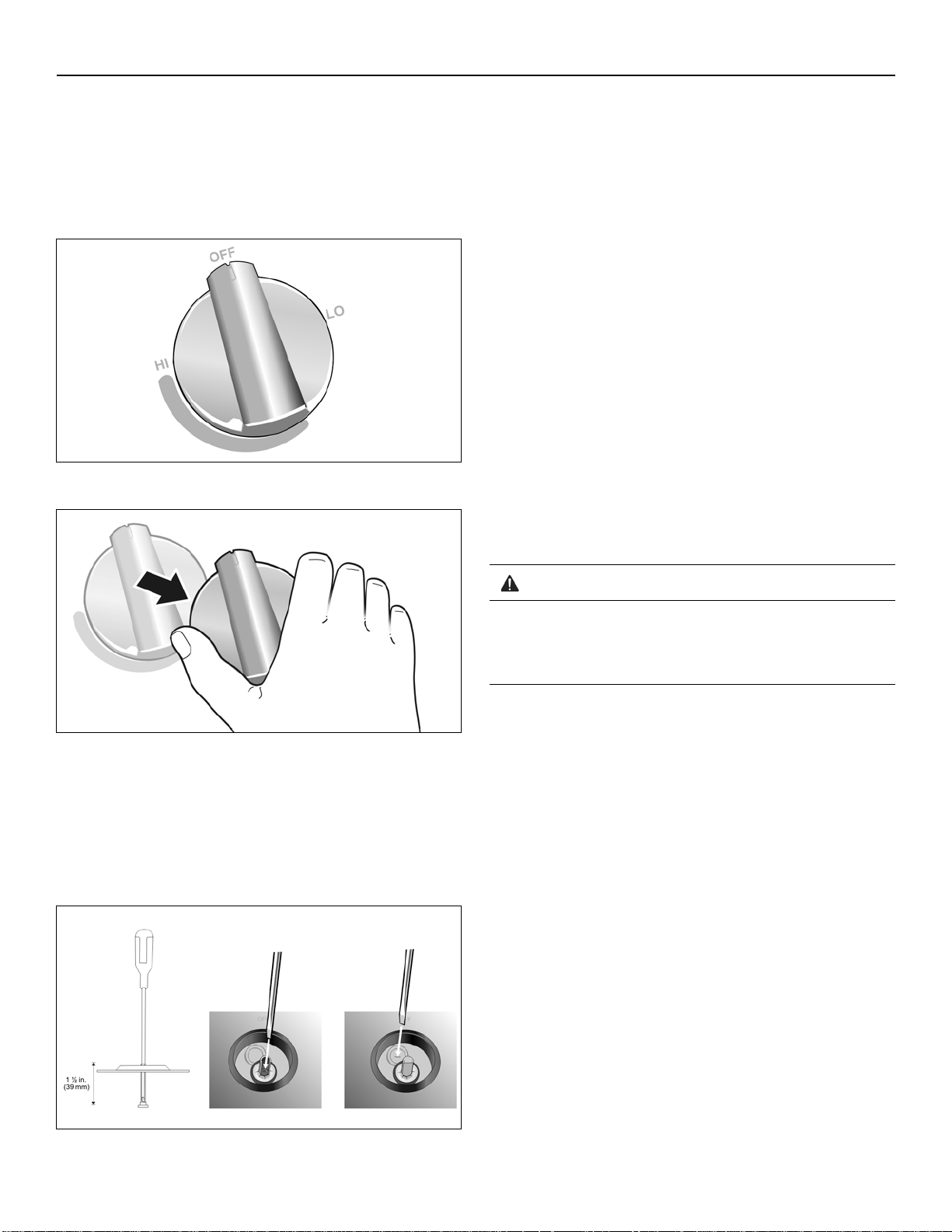
3. Locate the correct point of insertion for the long, thin
flat blade screwdriver to adjust the bypass jet (see the
following illustration).
a) Hollow stem valve - insert a long, thin flat blade
screwdriver in the hollow stem of the valve. The
adjustment screw is approximately 1 1/2” (39 mm)
from the top of the stem. The screwdriver slides
through a thin rubber barrier in the stem (helps
prevent damage in the case of a spill on the unit
surface).
b) Solid stem valve - insert a long, thin flat blade
screwdriver through the seal in the area shown.
3. Engage the tip of the screwdriver into the adjustment
screw by slowly turning the screwdriver and feeling for
the blade to engage the screw. Then turn the screw
clockwise about 70 degrees (less than 1/4 turn) until it
“bottoms out” (does not turn any further). The screw
does not take much pressure to turn. Stop when the
screw does not easily turn any further. Repeat for each
valve until all have been adjusted correctly.
4. Replace the knobs
Test the Installation
Test for Gas Leaks
Leak testing is to be conducted by the installer according to
the instructions given in this section.
Turn on gas. Apply a non-corrosive leak detection fluid to
all joints and fittings in the gas connection between the
shutoff valve and the cooktop. Include gas fittings and
joints in the cooktop if connections may have been
disturbed during installation. Bubbles appearing around
fittings and connections indicate a leak. An electronic Gas
Leak Detector can also be used.
If a leak appears, turn off the supply line gas shutoff valve
and tighten the leaking connections. Retest for leaks by
turning on the supply line gas shutoff valve. When the leak
check is complete (no bubbles appear), the test is
complete. Wipe off all detection fluid residue.
Check Manifold Gas Pressure
During any pressure testing of the gas supply piping
system at test pressures greater than 14" of water column
pressure (approximately ½" psig,
3.5 kPA
) it is necessary to
a. Hollow Stem
b. Solid Stem
WARNING
NEVER TEST FOR GAS LEAKS USING A FLAME.
If any leaks are detected, do not proceed past this
step until all leaks have been eliminated.
Loading ...
Loading ...
Loading ...