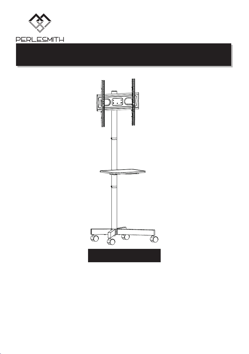
Model: PSTVMC06
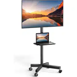
TV Cart Instruction Manual
V2.0(B)
Thank you for choosing this PERLESMITH product! At PERLESMITH we strive to
provide you with the best quality products and services in the industry. Should
you have any issues, please don't hesitate to contact us at
Technical Support:
1-800-556-6806 Mon-Fri 8am - 8pm(CST)
Other Info:
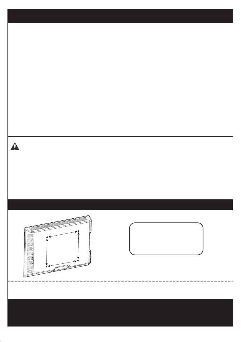
Minimum VESA pattern: 100mm/4 in (W)x100mm/4 in (H)
200 mm ≈ 7 7/8 in
400 mm ≈ 15 3/4 in
100 mm ≈ 4 in
300 mm ≈ 11 3/4 in
MAX:400mm/16 in
MAX:400mm/16 in
Check the VESA Pattern of Your TV before the Installation
If your TV VESA is greater than 400x400 mm/16x16 in or less than VESA
100x100mm/4x4 in, this TV cart is NOT compatible.
If this TV cart is NOT compatible, please contact customer service at
[email protected](US)/ [email protected](CA) to find a
compatible product.
Important Safety Information
• Please read through these instructions completely before attempting installation.
If you do not understand the instructions or have any concerns or questions,
please contact customer service at [email protected](US)/
• Check package contents against Supplied Parts and Hardware List to assure
that all components were received undamaged. Do not use damaged or defective
parts. lf you require replacement parts, contact customer service at
[email protected](US)/ [email protected](CA)
• Not all parts and hardware included will be used.
• Do not use this product for any purpose or in any configuration not explicitly
specified in this instruction. We hereby disclaim any liability for injury or damage
arising from incorrect assembly, incorrect mounting, or incorrect use of this
product.
Serious or fatal crushing injuries can occur from tip over. To help prevent tip over:
● Never allow children to climb, stand, hang, or play on any part of TV or TV cart.
● Use tip over restraint or anchor to attach the TV cart against wall.
Use of tip over restraints may only reduce, but not eliminate risk of tip over.
Tip over Warning
01 02 03 04 05 06 07 08 09 10 11 12 13 14 15 16

(4pcs)
(4pcs)
M4x12mm
M4x30mm
Bolt
TV2 (4pcs)
M6x16mm
Bolt
TV3 (4pcs) TV4 (4pcs)
M6x35mm
Bolt
TV5 (4pcs)
M8x50mm
Bolt
M8x25mm
Bolt
TV6 (4pcs)
TV7 (4pcs)
TV8 (8pcs)
Washer with
3 Holes
D8
2.5mm
Spacer
TV9 (4pcs)TV10 (4pcs)
10mm
Spacer
22mm
Spacer
Hardware for Attaching TV Brackets to TV
A (1pc)
M10x35mm
D10x30x2.5mm
01 (1pc)
07 (2pcs) 09 (1pc)
05 (1pc)
06 (1pc)
I (1pc)
08 (1pc)
02 (2pcs) 03 (2pcs) 04 (4pcs)
B (12pcs)
M6x12mm
D (2pcs)C (2pcs) E (2pcs) G (2pcs) F (1pc) H (1pc)
10 (2pcs) 11 (1pc) 13 (2pcs)12 (1pc)
Supplied Parts and Hardware
Supplied Parts
Hardware for Assembling the TV Cart
Phillips Screwdriver
Tools Needed (Not lncluded)
M5x55mm
5/32 in (4mm) 5/16 in (8mm)
10mm
12mm
TV1
Tube Connector
Long Square
Tube
Short Square
Tube
Caster Middle Pole
Lower Pole Pole Connector Upper Pole TV Plate
TV Bracket Shelf Connecting Plate Cable Clip
Washer
Nut
Bolt Safety
Lock
Bolt
Bolt
Small
Allen Key
Large
Allen Key
Wrench
Washer
(01)
(02)
Bolt
M8
01 02 03 04 05 06 07 08 09 10 11 12 13 14 15 16
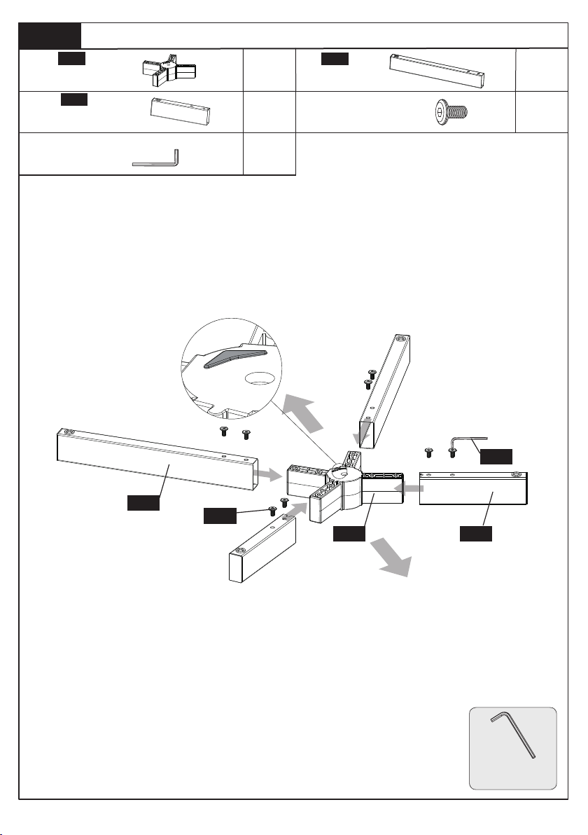
Step 1
Assemble the Base
Secure the short square tubes [03] and long square tubes [02] to the tube
connector [01] using bolts [B] and Allen key [F] .
5/32 in (4mm)
Small Allen Key
Tube Connector
B
5/32 in (4mm)
Small Allen Key
F
x1
x2
x2
x8
Long Square
Tube
x1
Short Square
Tube
M6x12mm
Bolt
01
02
03
01
03
02
B
F
Front Side
Back Side
Small Allen Key
01 02 03 04 05 06 07 08 09 10 11 12 13 14 15 16
06
06
A
H
01
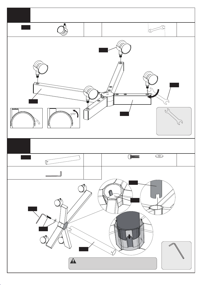
Step 2
Step 3
04
02
03
I
Screw the Casters [04] to the Short Square Tube [03] and
Long Square Tube [02]
Secure the Lower Pole [06] to the Center of the Tube
Connector [01]
15/32 in (12mm)
Wrench
Note: The groove on the lower pole [06] should be
aligned with the groove on the tube connector [01].
5/16 in (8mm)
Large Allen Key
Lock Unlock
x4
Caster
04
x1
Wrench
10mm
12mm
I
A
5/16 in (8mm)
Large Allen Key
H
x1
x1
x1
Lower Pole
06
M10x35mm
Bolt
Washer
D10x30x2.5mm
Large Allen Key
01 02 03 04 05 06 07 08 09 10 11 12 13 14 15 16
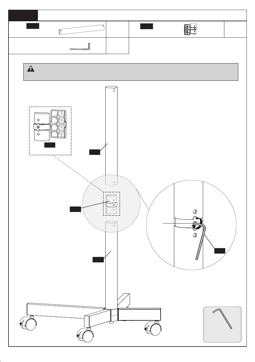
Step 4
06
05
07
F
07
Secure the Middle Pole [05] to Lower Pole [06]
Note: The convex grooves on the pole connector [07] should be aligned with the grooves on
the lower pole [06] and middle pole [05].
5/32 in (4mm)
Small Allen Key
4-1. Conenet the two parts of pole
connector [07].
4-2. Insert the assembled pole
connector [07] to the lower pole [06].
4-3. Insert the middle pole [05] to the
pole connector [07]
4-4.Tighten the preassembled setscrew
[T] to secure the two poles [05] and [06]
T
5/32 in (4mm)
Small Allen Key
F
x1
x1
x1
Middle Pole
05
Pole Connector
07
Small Allen Key
01 02 03 04 05 06 07 08 09 10 11 12 13 14 15 16
Step 5
C
Secure the TV Plate [09] to the Upper Pole [08]
5-1 Slide the upper pole [08] to the TV plate [09].
5-2 Secure the upper pole [08] to the TV plate [09] by tightening
the bolts [C] and nuts [D].
Upper Pole
D
x1
x1
x2
x2
TV Plate
x1
M8
Nut
08
09
Wrench
10mm
12mm
I
C
Bolt
08
09
D
I
01 02 03 04 05 06 07 08 09 10 11 12 13 14 15 16
5/32 in (4mm)
Small Allen Key
Step 6
07
08
05
F
Secure the Upper Pole [08] to the Middle Pole [05]
Front Side
Back Side
Note: Make sure the TV plate faces the front side of the TV cart.
6-1. Conenet the two parts of pole
connector [07].
6-2. Insert the assembled pole
connector [07] to the middle pole [05].
6-3. Insert the upper pole [08] to the
assembled pole connector [07].
6-4.Tighten the preassembled
setscrew [T] to secure the two poles
[05] and [08].
07
T
Note: The convex grooves on the pole
connector [07] should be aligned with
the grooves on the upper pole [08]
and middle pole [05].
x1 x1
Pole Connector
07
5/32 in (4mm)
Small Allen Key
F
Small Allen Key
01 02 03 04 05 06 07 08 09 10 11 12 13 14 15 16
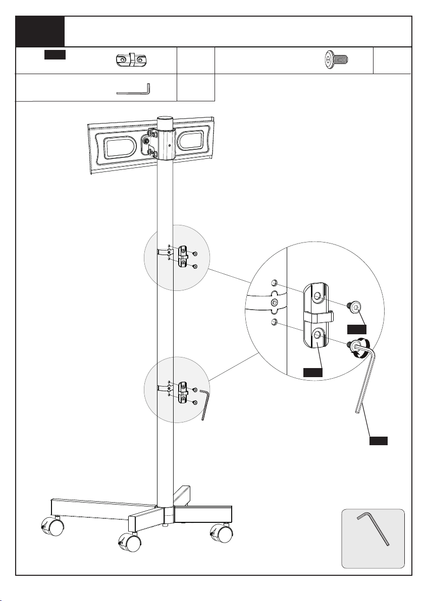
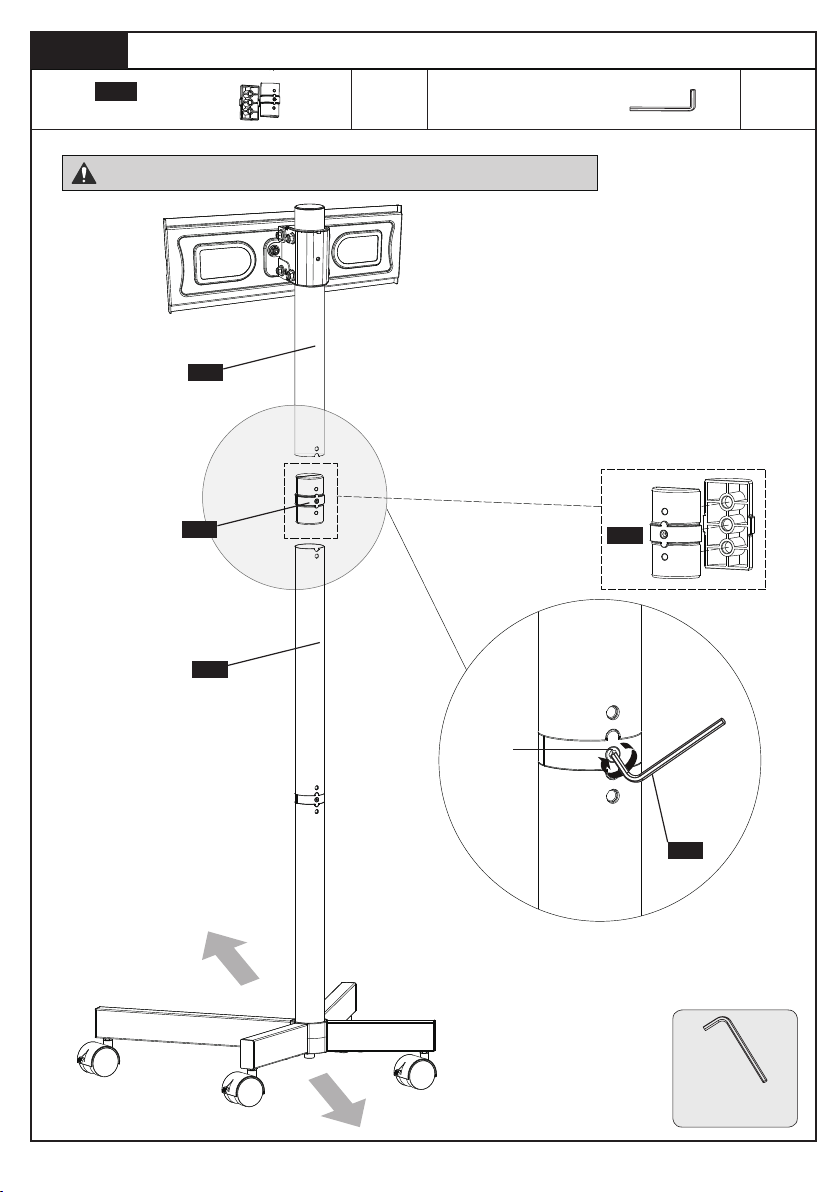
Step 7
13
B
F
Secure the Cable Clip [13] to the Connecting Parts
of the Poles
5/32 in (4mm)
Small Allen Key
5/32 in (4mm)
Small Allen Key
F
x2
x4
x1
Cable Clip
13
B
M6x12mm
Bolt
Small Allen Key
01 02 03 04 05 06 07 08 09 10 11 12 13 14 15 16
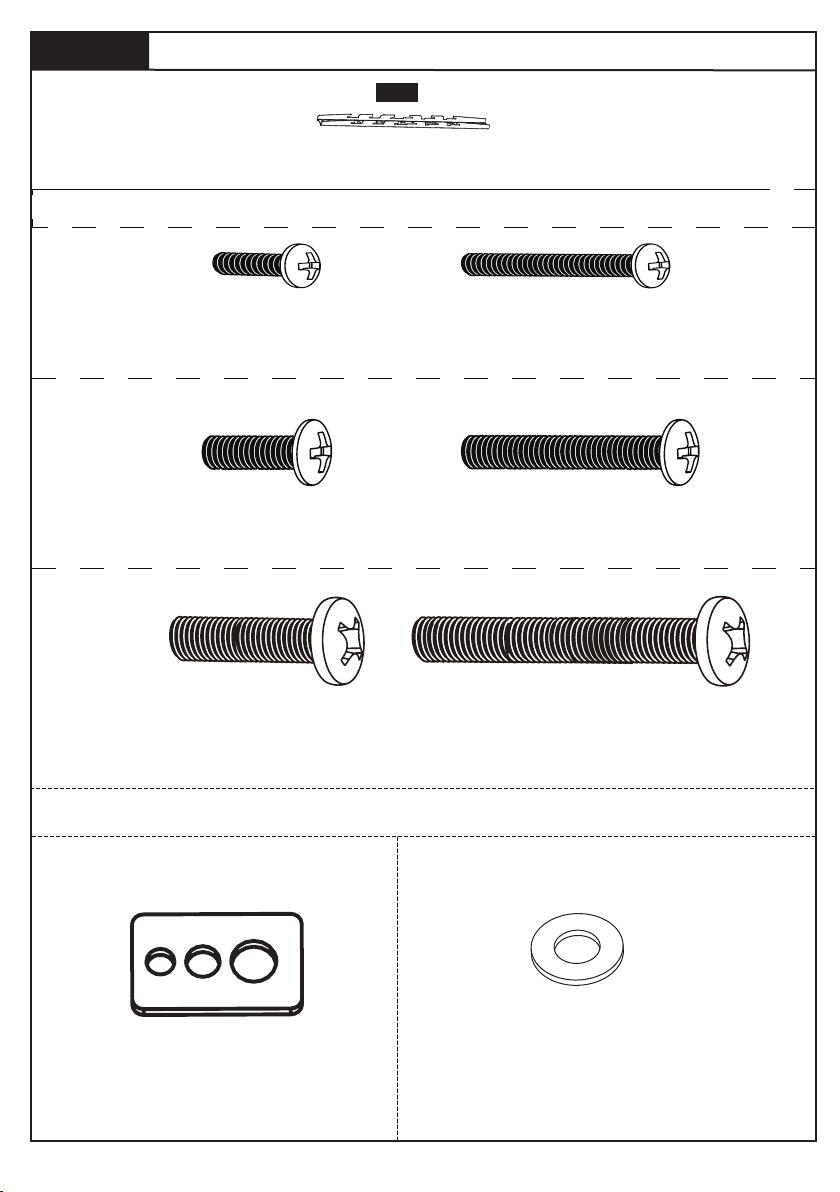
Step 8
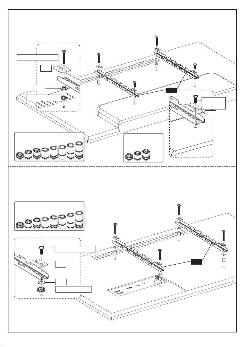
Secure the Brackets to the TV
Note: The bolts are shown in accordance with the actual size
M6
TV2 x4
M6 x 16mm
TV3 x4
M6 x 35mm
M4
TV1(01) x4
M4 x 12mm
TV1(02)x4
M4 x 30mm
M8
TV4x4
M8 x 25mm
TV5 x4
M8 x 50mm
X2
TV Bracket
10
Note: The washers and spacers are shown in accordance with the actual size
TV6x4
Washer
TV7 x4
D8 Steel Washer
01 02 03 04 05 06 07 08 09 10 11 12 13 14 15 16
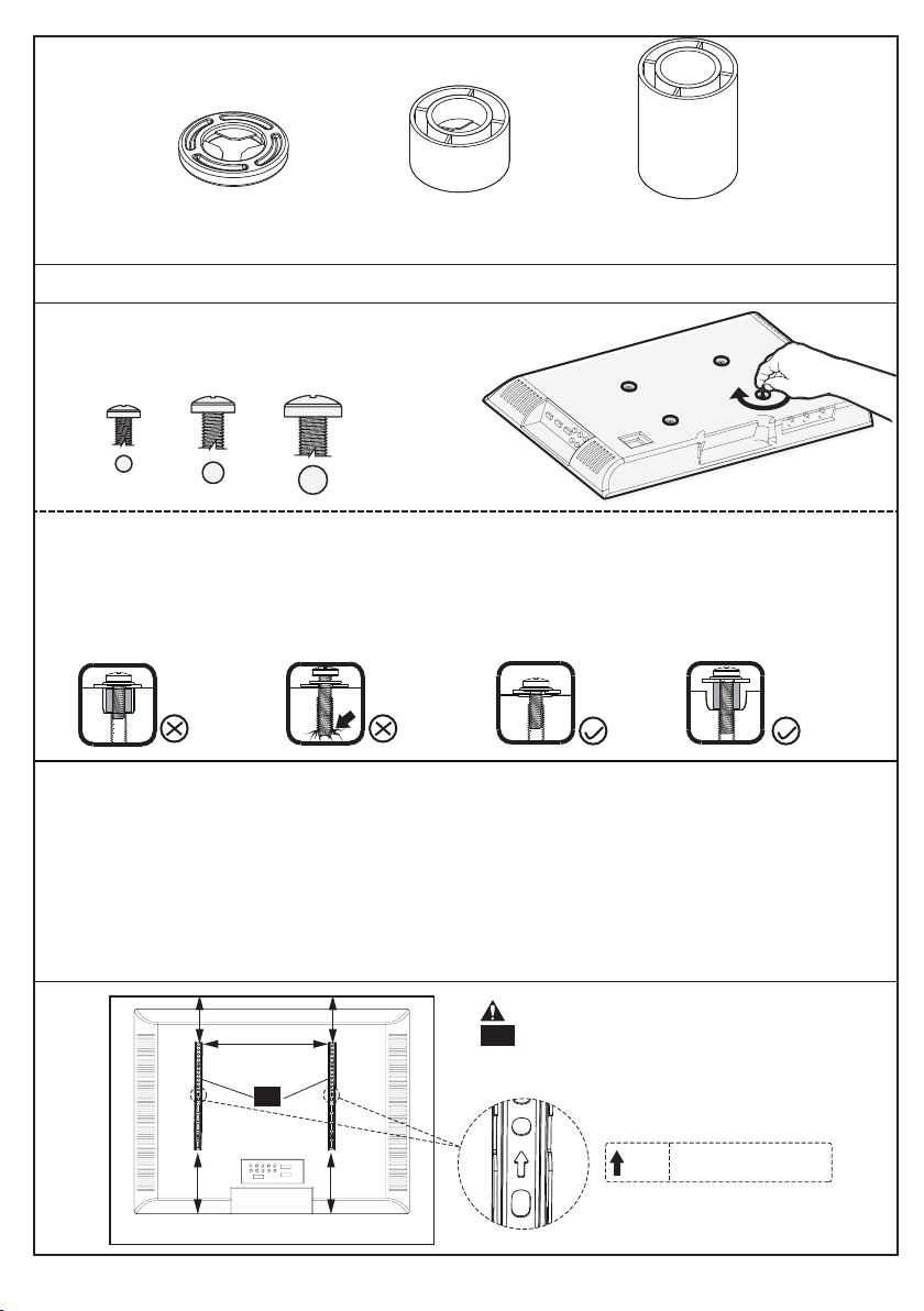
Only one bolt size fits your TV.
M6M4 M8
Bolt length:Verify adequate thread engagement with bolts or bolts/spacers combination.
We recommend thread engagement by at least 5 turns.
-Too short will not hold the TV.
-Too long will damage the TV.
Too Short
Too Long
Correct Correct
Select TV Bolts
Please Note: The provided TV bolts meet most of today's TVs design. However, some
TVs require special bolts which may not be in the hardware bag. In this case we offer our
“PSUHP" Universal Hardware Kit which provides a large selection of bolts that can meet
the demand of older and unique applications.
Please Note: When using the spacers it is important to note that they can be used in
multi-layers (meaning stacked). If you have any difficulty understanding how to install the
TV bolts or spacers, please contact customer service at [email protected] (US) /
[email protected] (CA).
CAUTION: Ensure the TV brackets
10 are EQUALLY CENTERED on your
TV and securely fastened in place.
10
UP
Note:
Keep the arrow up.
TV9 x4
φ8.5x18x10mm
TV10 x4
φ8.5x18x22mm
TV8 x8
φ8.5x18x2.5mm
Spacers
[if needed]
01 02 03 04 05 06 07 08 09 10 11 12 13 14 15 16

Option B (For Round Back TV)
Option A (For Flat Back TV)
(If needed)
10
10
TV1(01)/TV2/TV4
TV8/TV9
TV6
TV7
TV6
TV8/TV9/TV10
TV1(02)/TV3/TV5
Alternate Spacer Setups
Alternate Spacer Setups
TV7
TV7
01 02 03 04 05 06 07 08 09 10 11 12 13 14 15 16
Spacers may be necessary for 2 holes ONLY.
Option C (For TV with A “Bump”)
Option D
For cable interference or inset holes, use spacers [TV8/TV9/TV10] to
create extra space between the TV and TV brackets
(If needed)
10
10
TV1(01)
/TV2/TV4
TV6
TV8/TV9/TV10
TV1(02)/TV3/TV5
TV8/TV9/TV10
TV1(02)/TV3/TV5
TV6
TV6
Alternate Spacer Setups
Alternate Spacer Setups
Alternate
Spacer Setups
TV7
TV7
01 02 03 04 05 06 07 08 09 10 11 12 13 14 15 16
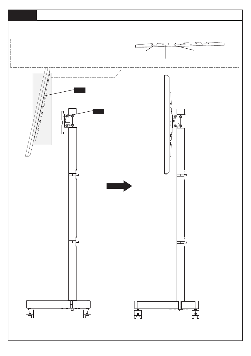
Step 9
10
09
Hang TV to TV Plate [09]
9-1 Hang the TV with brackets to the TV plate
9-2 Push the bottom of the TV to TV plate
TV brackets are three-height-adjustable.
You can choose the proper height.
The first choice
The second choice
The third choice
01 02 03 04 05 06 07 08 09 10 11 12 13 14 15 16
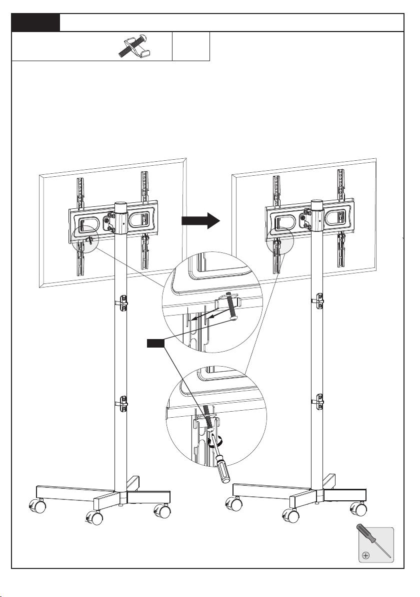
Step 10
G
Insert the safety locks [G] into the upward facing hooks at the midway to
lower part of the TV bracket. Please note this is where the lower part of
the TV bracket meets the lower part of TV plate. Then tighten the bolts of
the safety lock [G] until the bolts touch the TV plate.
Secure TV to TV Plate [09]
Note: Please note that there is no holes on the TV plate.
x2
Safety Lock
G
01 02 03 04 05 06 07 08 09 10 11 12 13 14 15 16
5/32 in (4mm)
Small Allen Key
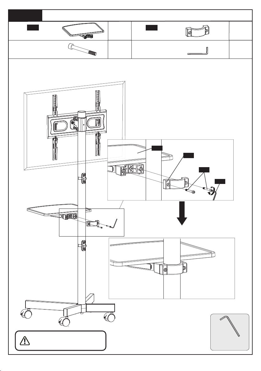
Step 11
Secure the shelf [11] to the pole using connecting plate [12], bolts [E] and
Allen key [F].
Secure the Shelf [11] to the Pole
You may need assis-
tance with this step.
E
F
12
11
Shelf
x1
x1
x2
x1
Connecting Plate
11
12
M5x55mm
Bolt
E
5/32 in (4mm)
Small Allen Key
F
01 02 03 04 05 06 07 08 09 10 11 12 13 14 15
16
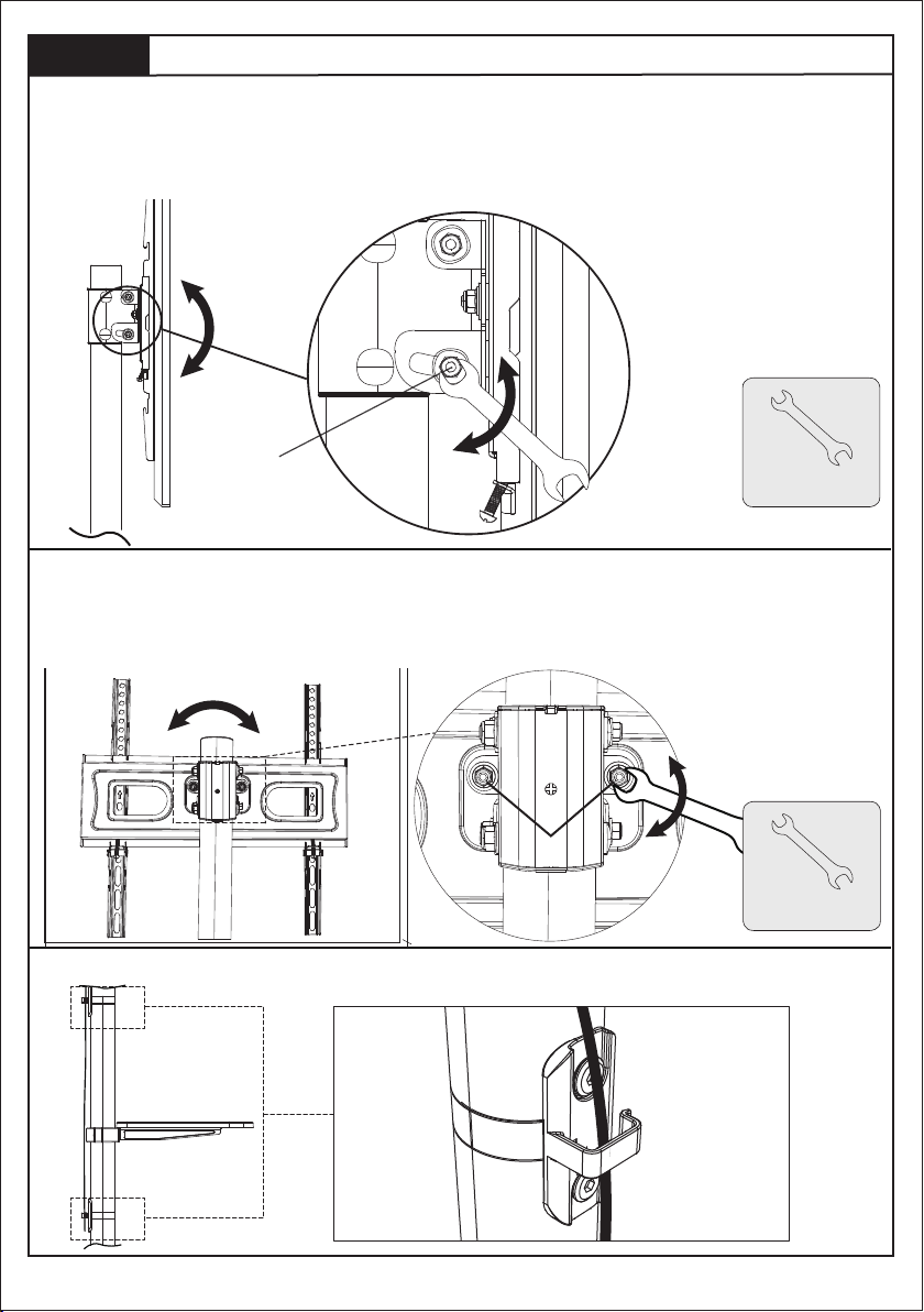
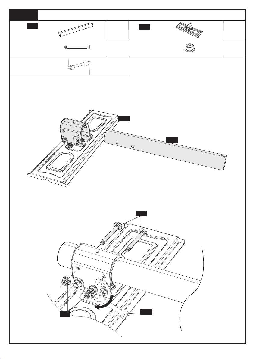
3/8 in (10mm)
Wrench
12-1 Tilt Adjustment
12-2 Level Adjustment
1. Slightly loosen the both tilt nuts [L].
2. Adjust TV to your desired tilt angle.
3. Tighten the both tilt nuts [L] to secure the TV in place.
L
12-3 Manage the Wires
Step 12
Adjustments
1. Slightly loosen the both nuts [S] using wrench.
2. Level the TV.
3. Retightent both nuts [S] to secure the TV in place.
S
3/8 in (10mm)
Wrench
01 02 03 04 05 06 07 08 09 10 11 12 13 14 15
16


Thank you again for choosing
this PERLESMITH product!
All of us at PERLESMITH do appreciate your product purchase. We hope that you
are as happy with your product as we designing and manufacturing it for you. We
strive to provide you with the best quality products and services in the industry. If
you have any questions please don't hesitate to contact us at
Technical Support:
1-800-556-6806 Mon-Fri 8am - 8pm(CST)
Other Info: