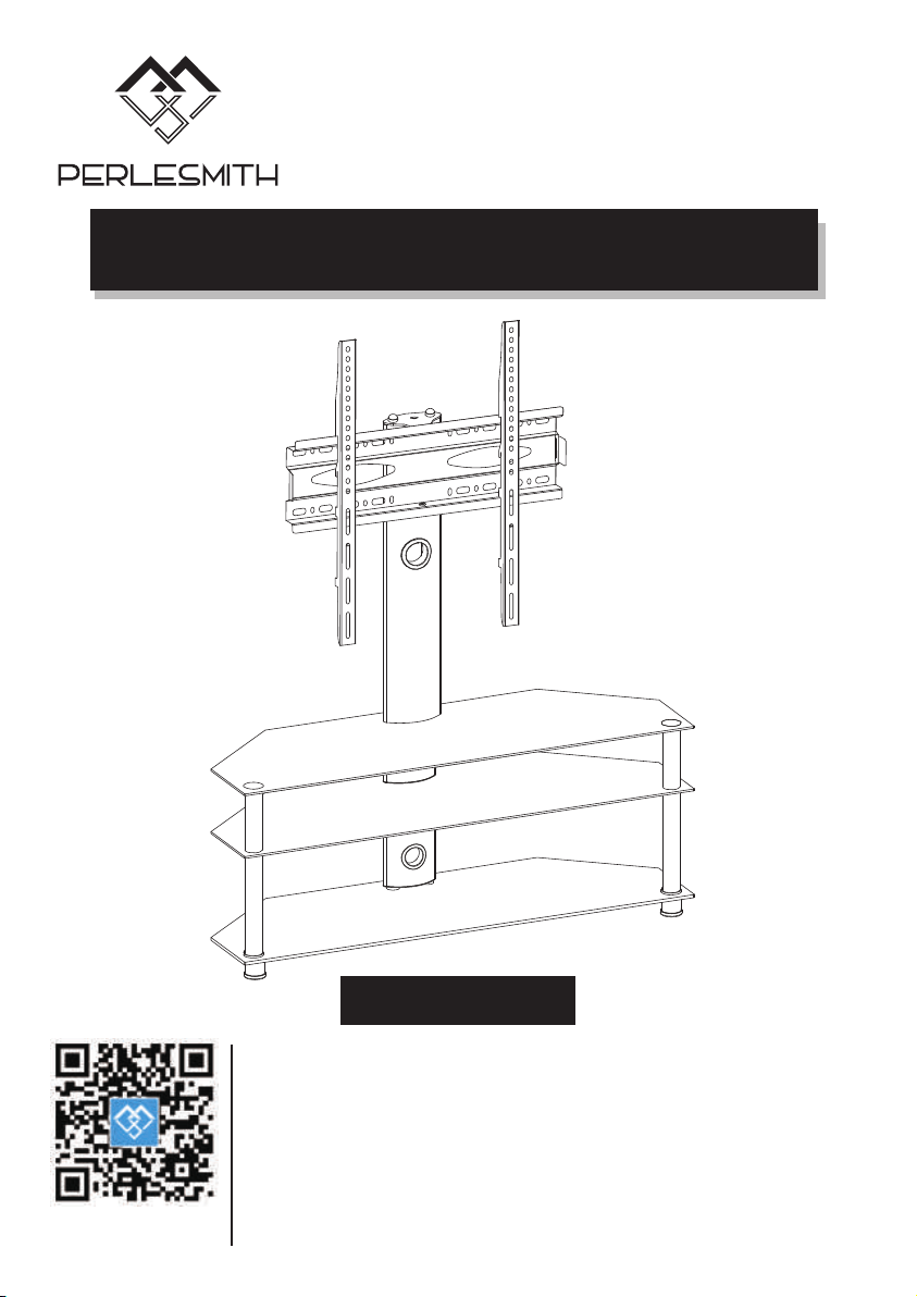
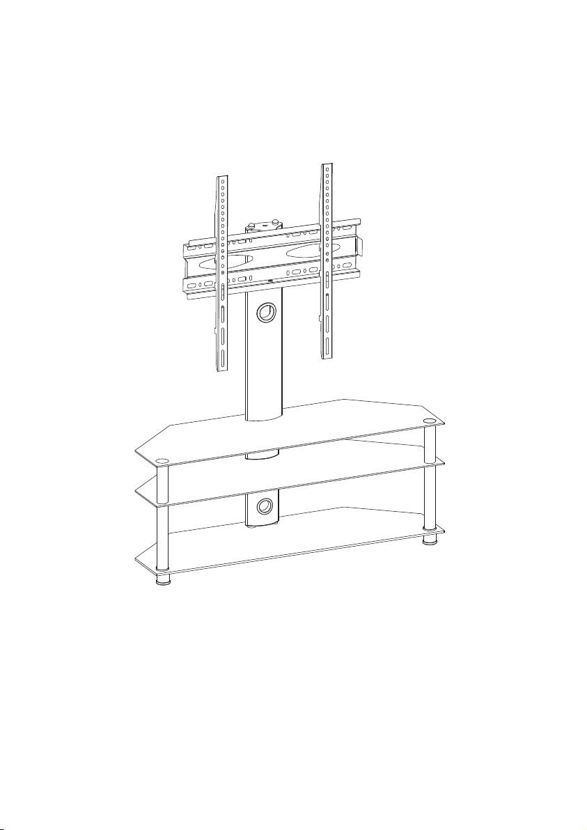
Model: PSFS04
TV Stand Instruction Manual
V2.0
Thank you for choosing this PERLESMITH product! At PERLESMITH we
strive to provide you with the best quality products and services in the
industry. Please share your experience of our product with others at
www.perlesmith.com/pages/reviews if you are satisfied. Should you have
any issues, please don't hesitate to contact us.
Technical Support:
1-800-556-6806 Mon-Fri 10am - 5pm (PST) (USA) (CAN)
Other Info:
[email protected] (US)
[email protected] (CA)
Website:
www.perlesmith.com
01
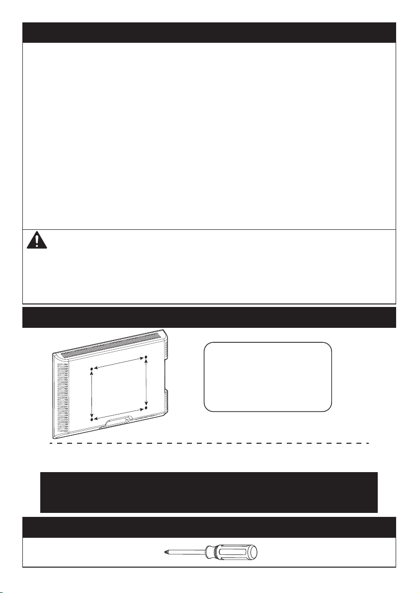
Check the VESA Pattern of TV before the Installation
100 mm ≈ 4 in.
200 mm ≈ 7 7/8 in.
300 mm ≈ 11 3/4 in.
400 mm ≈ 15 3/4 in.
600 mm ≈ 23 5/8 in.
Minimum VESA pattern: 100mm/4 in.(W)x100mm/4 in.(H)
If your TV VESA is greater than 600x400 mm/23.6x16in. or less
than VESA 100x100mm/4x4 in., this TV stand is NOT compatible.
MAX: 600mm/23.6 in.
MAX: 400mm/16 in.
Tools Needed (Not lncluded)
• Philips Screwdriver
IMPORTANT SAFETY INFORMATION
Please carefully read all instructions before attempting installation. If you do
not understand the instructions or have any concerns or questions, please
contact customer service at [email protected] (US)/
[email protected] (CA).
• Check package contents against Supplied Parts and Hardware List to assure
that all components were received undamaged. Do not use damaged or
defective parts. If you require replacement parts, contact customer service at
[email protected] (US)/ [email protected] (CA).
• Not all parts and hardware included will be used.
• Do not use this product for any purpose or in any configuration not explicitly
specified in this instruction. We hereby disclaim any liability for injury or
damage arising from incorrect assembly, incorrect mounting, or incorrect use
of this product.
• Please check www.perlesmith.com for more products and company
information.
If this TV stand is NOT compatible, please contact customer service
at [email protected] (US)/ [email protected] (CA)
to find a compatible product.
Serious or fatal crushing injuries can occur from tip over. To help prevent tip over:
● Never allow children to climb, stand, hang, or play on any part of TV or TV stand.
● Use tip over restraint or anchor stand to wall.
Use of tip over restraints may only reduce, but not eliminate risk of tip over.
Tip over Warning
02
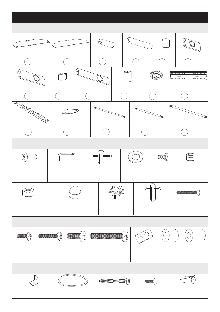
Supplied Parts and Hardware
Supplied Parts
Tempered Glass
Base
Tempered Glass
Base
x1
1
Support Pillar
x2
3
Support Pillar
x2
4
x2
2
Foot
x2
5
Support Pillar
x1
6
Support Pillar
x1
7
Support Pillar
x1
10
Support Pillar
x1
9
M6x470mm
Connecting Rod
x2
15
M8x465mm
Connecting Rod
x2
16
x2
14
Transfer Plate
x2
11
Foot Cover
Supplied Hardware for Assembling the TV stand
M8x22mm
Bolt
M8
Nut
M8x16mm
Bolt
M8
Rubber Washer
x2
A
M10 Nut
x2
D1
Decorative Cap
x2
D2
Cable Clip
x2
E
13/64 in. (5mm)
Allen Key
x1
B1
17#
Wrench
x1
B2
x2
C1
x2
C2
x2
C3
13# Wrench
x1
F1
Foot
x1
8
x2
17
M10x620mm
Connecting Rod
Supplied Hardware for Attaching TV Brackets to TV
M6x15mm
Bolt
x4
S1
Mounting Bracekt
a x2
Steel Cable
b x1
Long Screw
c x1
Short Bolt
d x1
Plastic Anchor
e x1
M6x30mm
Bolt
x4
S2
M8x20mm
Bolt
x4
S3
M8x50mm
Bolt
x4
S4
M6/M8
Washer
x4
S5
Supplied Parts and Hardware for Attaching the TV stand to the wall (Optional)
x1
12
TV Plate
x2
13
TV Bracket
Bolt
x1
F2
L16mm
Spacer
x4
S6-1
L22mm
Spacer
x4
S6-2
03
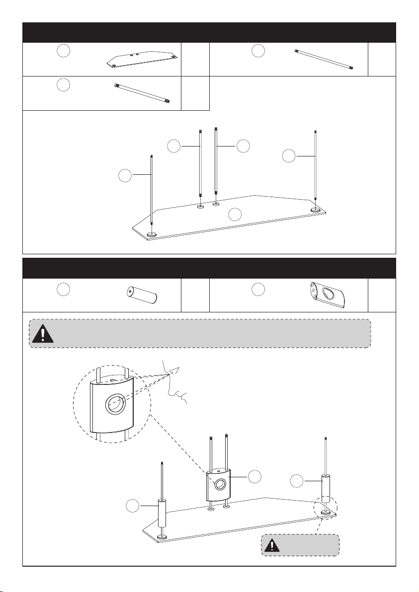
x1
1
1
15
15
M6x470mm
Connecting Rod
Tempered Glass
Base
x2
16
Step 1 Screw the Connecting Rods [15 and 16] to the Tempered Glass Base [1]
M8x465mm
Connecting Rod
x2
15
16
x2
3
Support PillarSupport Pillar
x1
Step 2 Slide the Support Pillars to the Connecting Rods
6
No Spacer
3
6
Note: Make sure the two connecting rods can pass through the
two holes at the top of the support pillar [6]
3
16
Back
04
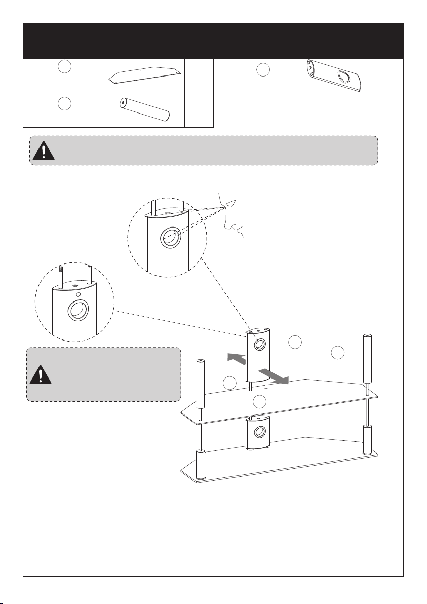
Note: Make sure the side
with the small hole on the
support pillar [7] faces
the back of the stand
4
4
7
Note: Make sure the two connecting rods can pass through the
two holes at the top of the support pillar [7]
Front
4
Support Pillar
2
Tempered Glass
Base
Support Pillar
x1
7
x2
x1
2
Step 3 Secure Tempered Glass Base [2] and the Support Pillar
[4 and 7] to the Connecting Rods
05
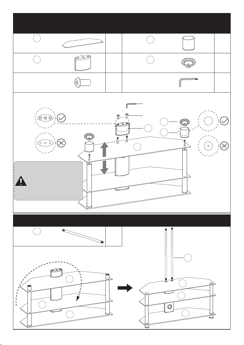
1
1
2
2
x1
2
2
Foot
Tempered Glass
Base
x2
Step 4 Secure Tempered Glass Base [2] and the Feet [5 and 8]
to the Connecting Rods
5
x1
8
Foot Cover
Foot
x2
x2
13/64 in. (5mm)
Allen Key
M8x22mm
Bolt
x1
11
A B1
B1
x2
M10x620mm
Connecting Rod
Step 5 Secure the Connecting Rod [17] to the Tempered Glass Base [1]
Make sure matte
side of tempered
glass base [2]
faces upward as
shown in this figure
Turn Over
17
17
Down
UP
5
8
11
A
2
2
1
06
1
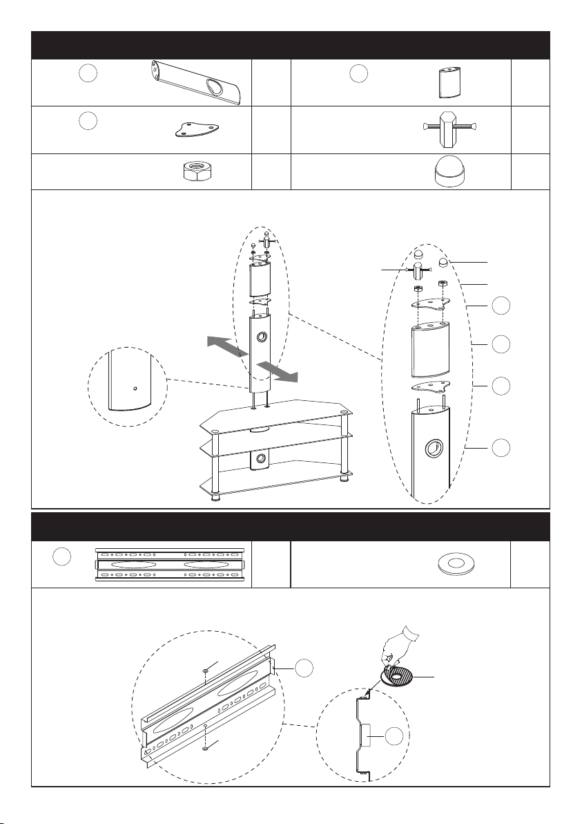
Step 6 Secure Support Pillar [9 and 10] to the Tempered Glass Base [1]
x1
Support PillarSupport Pillar
x1
x2
17#
Wrench
Transfer Plate
x1
x2
Decorative CoverM10 Nut
x2
D1 D2
B2
D2
D1
9
9
14
14
14
x1
TV Plate
Step 7 Attach the Washer [C1] to TV Plate [12]
x2
M8
Rubber Washer
Attach the rubber washer [C1] to the center of top and bottom of the TV
Plate [12]. Make sure the hole of washer [C1] is align with the center hole on
the TV Plate [12].
Note: Make sure the side
with the small hole on the
support pillar [9] faces
the back of the stand
Please don’t fully tighten nuts [D1]
until Step 8 to fix all the bolts in the
right holes.
Side View
B2
12
12
C1
C1
C1
12
Back
Front
10
10
C1
07
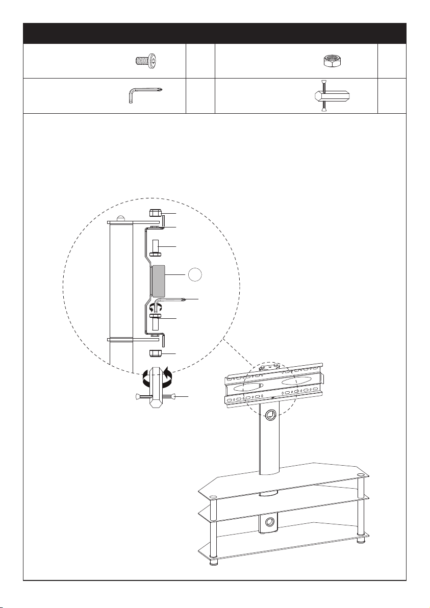
x2
M8
Nut
M8x16mm
Bolt
x2
Step 8 Secure the TV Plate [12] Support Pillar
x1
13#
Wrench
13/64 in. (5mm)
Allen Key
x1
Make sure all the bolts are fully tightened before putting on your TV.
The hole on the TV Plate [12] should be aligned with the hole on the Transfer
Plate [14].
F1B1
C2 C3
Side View
F
C2
C2
C3
C3
15
B1
C1
08
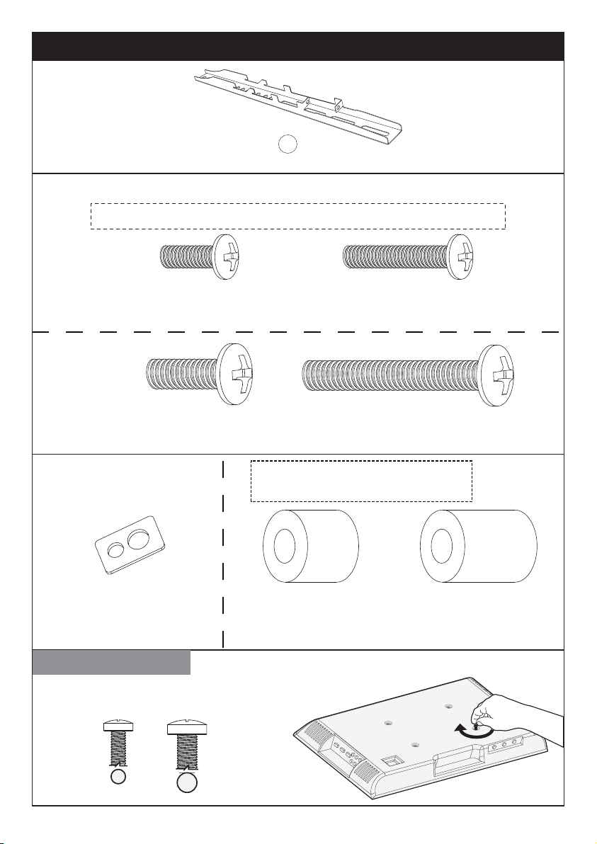
M6x15mm
S1 x4
M6x30mm
S2 x4
Note: The bolts are shown in accordance with the actual size
TV Bolts (Only one bolt size fits your TV)
M8x50mm
S4 x4
M8x20mm
S3 x4
Note: The spacers are shown in
accordance with the actual size
Select TV Bolts
Only one bolt size fits your TV.
M6 M8
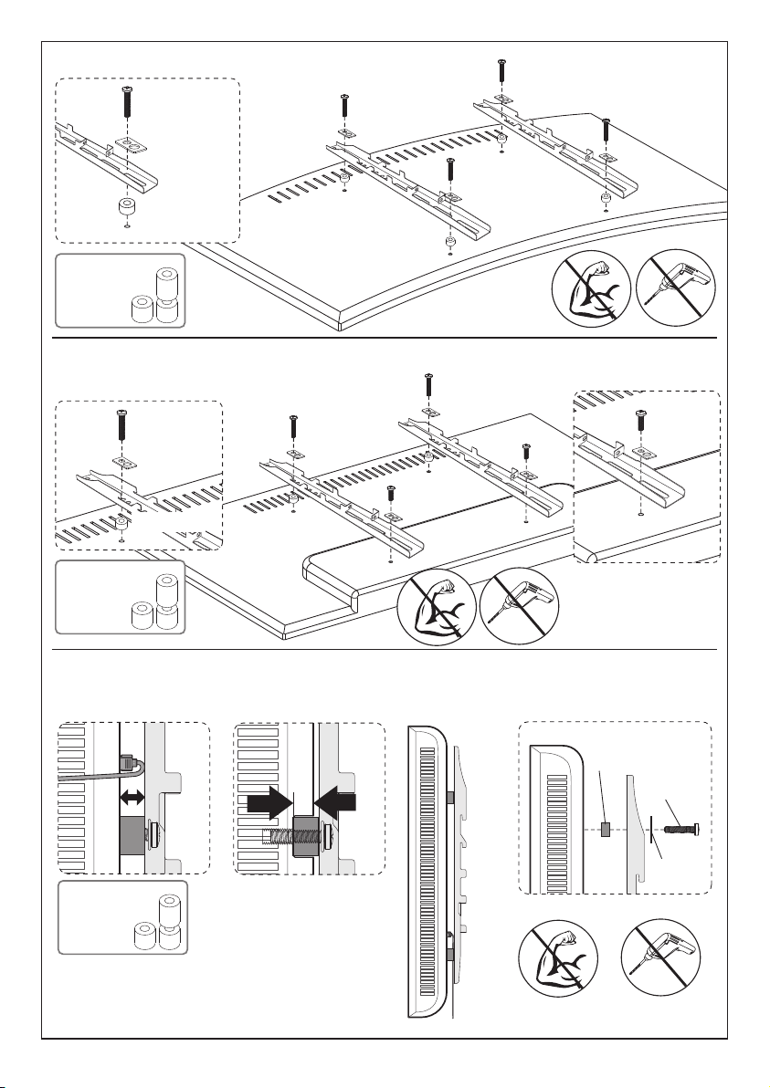
Step 8 Secure the TV Brackets [13] to TV
M6
M8
TV Bracket
x2
13
M6/M8
Washer
S5 x4
L16mm
Spacer
S6-1 x4
L22mm
Spacer
S6-2 x4
09
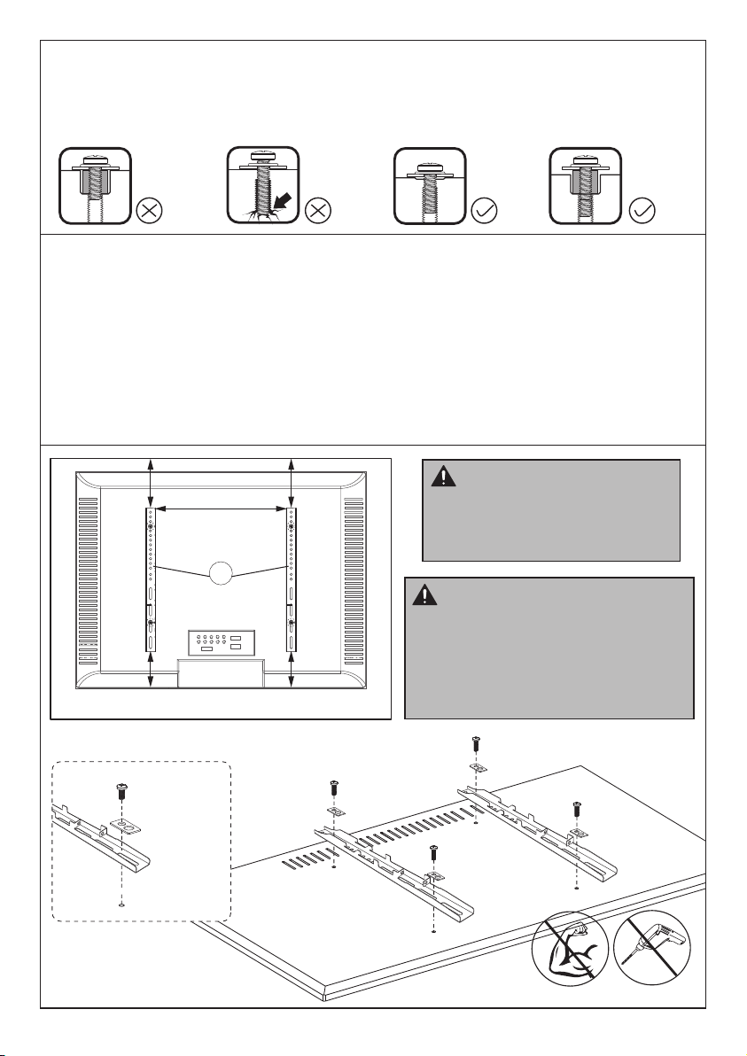
Bolt length: Verify adequate thread engagement with bolts or bolts/spacers
combination. We recommend thread engagement by at least 5 turns.
-Too short will not hold the TV.
-Too long will damage the TV.
Too Long
Correct Correct
Too Short
Please Note: The provided TV bolts meet most of today’s TVs design.
However, some TVs require special bolts which may not be in the hardware
bag. In this case we offer our “PSUHP" Universal Hardware Kit which
provides a large selection of bolts that can meet the demand of older and
unique applications.
Please Note: When using the spacers it is important to note that they can be
used in multi-layers (meaning stacked). If you have any difficulty understand-
ing how to install the TV bolts or spacers, please contact customer service at
[email protected] (US)/ [email protected] (CA).
CAUTION: Ensure the TV
brackets [13] are EQUALLY
CENTERED on your TV and
securely fastened in place.
Please note: The bolt hole
locations on your TV may vary in
accordance of the manufacturers
design of the TV. We are only
illustrating possible locations of
the bolt holes.
13
Option A (For Flat Back TV)
S5
S1/S3
10
Option D
Option B (For Round Back TV)
Spacers may be necessary for 2 holes ONLY.
Option C (For TV with A “Bump”)
For cable interference or inset holes, use spacers [S6-1] and [S6-2] to create extra
space between the TV and TV brackets
S5
S2/S4
S6-1/S6-2
S1/S3
S5
S2/S4
S6-1/S6-2
S5
Alternate
Spacer
Setups
S5
S2/S4
S6-1/S6-2
Alternate
Spacer
Setups
Alternate
Spacer
Setups
11
Philips
Screwdriver
(Not lncluded)
①
②
TV brackets are two-height-adjustable.
You can choose the proper height.
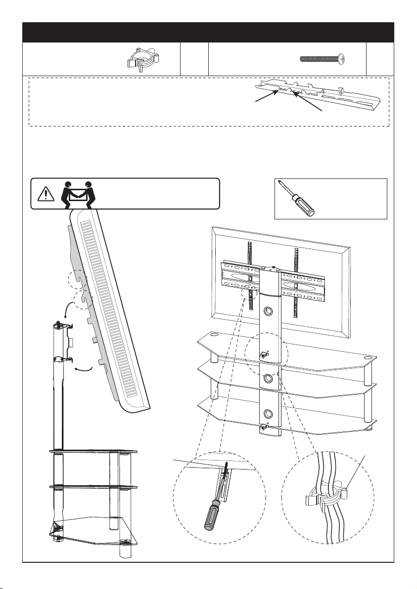
Step 9-1 Hang the TV with brackets to the TV plate
Step 9-2 Push the bottom of the TV to TV plate
Step 9-3 Tighten the bolts [F2] until the bolts touch the TV plate.
Manage the wires
The First Choice
The Second Choice
③
HEAVY! You may need
assistance with this step.
Step 9 Secure TV to TV Plate [12] and Manage the Wires
E
F2
x2
Cable Clip
E
Bolt
x2
F2
12
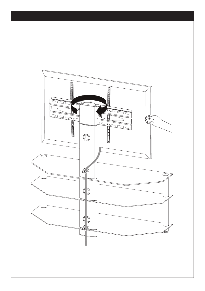
If necessary, the TV plate or TV can be swivelled manually.
Step 10 Adjust the Swivel Angle
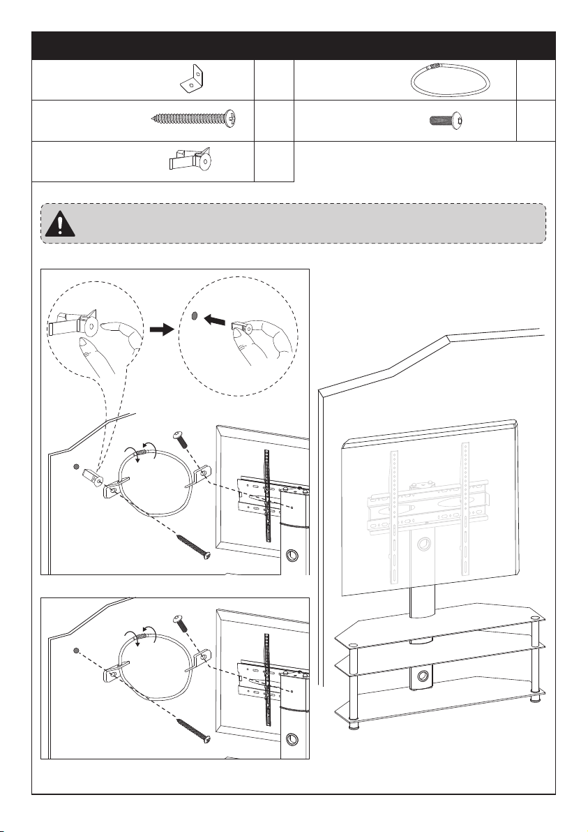
Step 11 Attach the TV Stand to the Wall (Optional)
WALL
This unit is just for sample display.
Note: It is recommend to use this tipping restraint to attach this unit
to the wall, to prevent possible accidents and/or injuries.
Solid Concrete or
Concrete Block
Wood Studs
x2 x1
x1 x1
x1
Plastic Anchor
e
Long Screw
c
Mounting Bracket
a
Steel Cable
b
Short Bolt
d
Thank you again for
choosing this PERLESMITH product!
All of us at PERLESMITH do appreciate your product purchase. We hope that
you are as happy with your product as we are designing and manufacturing it
for you. We strive to provide you with the best quality products and services in
the industry. Please share your experience of our product with others at
www.perlesmith.com/pages/reviews if you are satisfied. Should you have any
issues, please don't hesitate to contact us.
Technical Support: 1-800-556-6806 Mon-Fri 10am - 5pm (PST) (USA) (CAN)
Other Info: [email protected] (US)/[email protected] (CA)
Please check www.perlesmith.com for more products and company information.
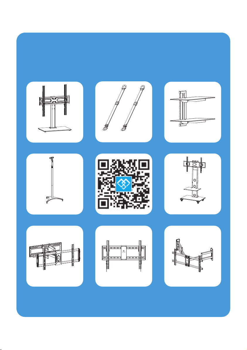
Perlesmith offers products
in these categories
Anti-tip Straps
TV Stands
AV Shelves
Speaker Stands
TV Carts
Full Motion Mounts Tilt Mounts Corner Mounts
Please remember us when you need one.
Perlesmith offers products
in these categories
Anti-tip Straps
TV Stands AV Shelves
Speaker Stands TV Carts
Full Motion Mounts Tilt Mounts Corner Mounts
Please remember us when you need one.