Use & Care Guide
Manual de Uso y Cuidado
English / Espa_ol
Models/Modelos: 148.16156210/148.16157210
Items / Arficulos: 640-03838924-3 / 640-03838925-0
I(enmore
@ @ @
@
P/N S3218AN-Manual
Sears Brands Management Corporation
Hoffman Estates, IL 60179 U.S.A.
www.kenmore.com
www.sears.com
www.kmart.com
If you smell gas:
1. Shut off gas to the appliance.
2. Extinguish any open flame.
3. Open lid.
4. If odor continues, keep away from the
appliance and immediatelycall your gas
supplier or your fire department.
1. Do not store or use gasoline or other
flammable liquids or vapors in the vicinity
of this or any other appliance.
2. An LP cylinder not connected for use shall
not be stored in the vicinity of this or any
other appliance.
Installation Safety Precautions
• Use grill, as purchased, only with LP (propane) gas and the
regulator/valve assembly supplied. A conversion kit must
be purchased for use with natural gas.
• Grill installation must conform with local codes, or in their
absence of local codes, with either the National Fuel Gas
Code,ANSI Z223. 1/NFPA 54, Natural Gas and Propane
Installation Code, CSA B149. 1,or Propane Storage and
Handling Code, B149.2, or the Standard for Recreational
Vehicles,ANSl A 119.2/NFPA 1192,and CSA Z240 RV
Series, Recreational Vehicle Code,as applicable.
• All electrical accessories (such as rotisserie) must be
electrically grounded in accordance with local codes, or
National Electrical Code, ANSI / NFPA 70 or Canadian
Electrical Code, CSA C22. 1. Keep any electrical cords
and/or fuel supply hoses away from any hot surfaces.
• This grill is safety certified for use in the United States
and/or Canada only. Do not modify for use in any other
location. Modification will result in a safety hazard.
Call Grill Service Center For Help And Parts
If you have questions or need assistance during assembly,
please call 1-800-482-0131. You will be speaking to a
representative of the grill manufacturer and not a Sears
employee. To order new parts call Sears at
1-800-4-MY-HOME.
Product Record
IMPORTANT: Fill out the product record information
below.
Model Number
Serial Number
See rating label on grill for serial number.
Date Purchased
.............................................CAUTION...............................................
For residential use only. Do not use for
commercial cooking.
© 2012 KCD IP, LLC
Safety Symbols
The symbols and boxes shown below explain what each
heading means. Read and follow all of the messages found
throughout the manual.
DANGER: Indicates an imminently hazardous
situation which, if not avoided, will result in death or
serious injury.
WARNING: Indicates an potentially hazardous
situation which, if not avoided, could result in death
or serious injury.
.............................................CAUTION.............................................
CAUTION: Indicates a potentially hazardous
situation or unsafe practice which, if not avoided,
may result in minor or moderate injury.
ForYourSafety.................................. 2
GrillServiceCenter............................... 2
ProductRecordInformation........................ 2
SafetySymbols.................................. 2
InstallationSafetyPrecautions....................... 2
KenmoreGrillWarranty........................... 3
UseandCare................................ 4-11
TransformerConnectionInstruction............................12
NaturalGasConversionKit........................ 14
PartsList...................................... 15
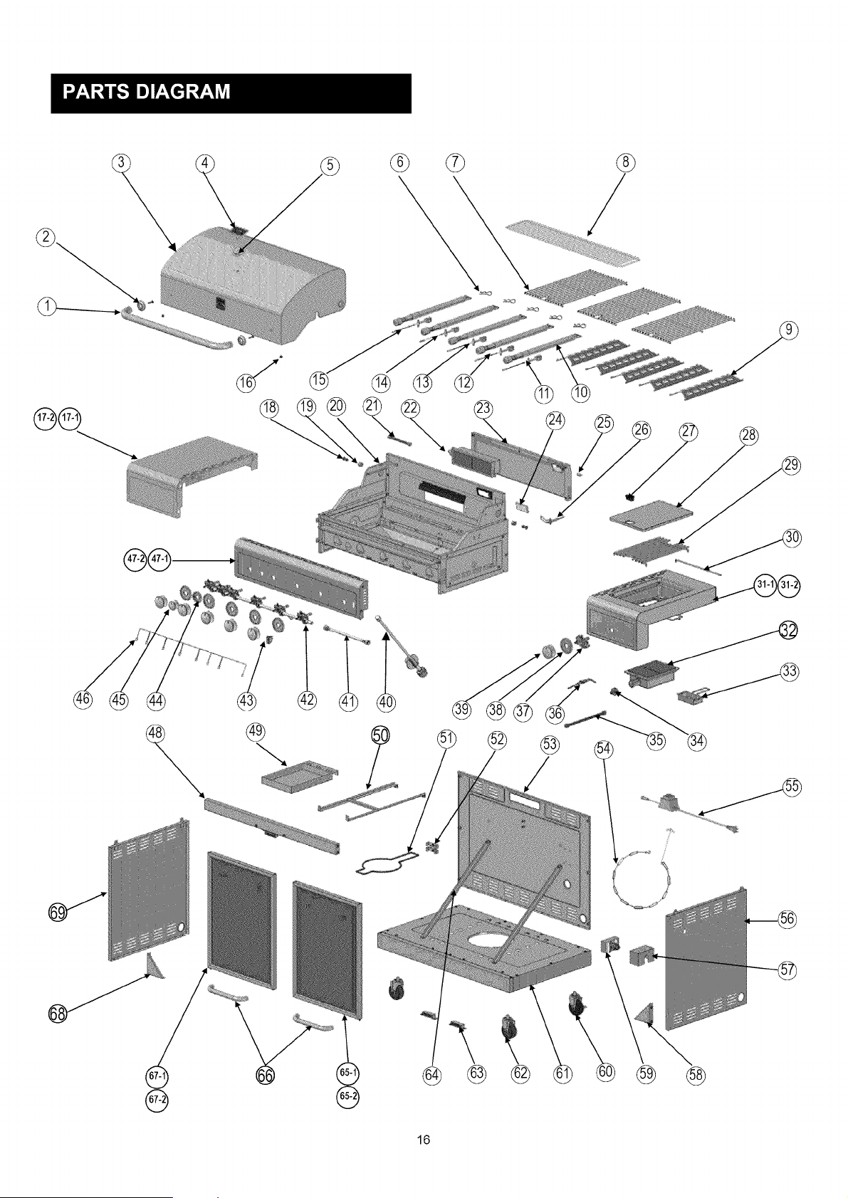
PartsDiagram................................... 16
Assembly.................................... 17-28
NaturalGasConversionInstructions.............. 29-33
Troubleshooting............................... 34-36
Repair Protection Agreements
Congratulations on making a smart purchase. Your new
Kenmore ®productis designed and manufactured for years of
dependable operation. But like all products, it may require
repair from time to time. That's when having a Repair
Protection Agreement can save you money and aggravation.
Purchase a Repair Protection Agreement now and protect
yourself from unexpected hassle and expense.
Here's what the Repair Protection Agreement includes:
[] Expert service by our 10,000 professional repair
specialists
[] Unlimited service and no charge for parts and labor on
all covered repairs
[] Product replacement up to $1500 if your covered
product can't be fixed
[] Discount of 25% from regular price of service and
related installed parts not covered by the agreement; also,
25% off regular price of preventive maintenance check
[] Fast help by phone -we call it Rapid Resolution -
phone support from a Sears representative. Think of us
as a "talking owner's manual."
Once you purchase the Repair Protection Agreement, a simple
phone call is all that it takes for you to schedule service. You
can call anytime day or night, or schedule a service
appointment online.
The Repair Protection Agreement is a risk-free purchase. If you
cancel for any reason during the productwarranty period, we
will provide a full refund. Or, a prorated refund anytime after
the product warranty period expires. Purchase your Repair
Protection Agreement today!
Some limitations and exclusions apply,
For prices and additional information call 1-800-827-6655.
Sears Installation Service
For Sears professiona/ installation of home appliances, garage
door openers, water heaters, and other major home items, in
the U.S.A. call 1-800-4-MY-HOME®
Kenmore Full Warranty
If this grill fails due to a defect in material or workmanship
within one year from the date of purchase, call 1-800-4-MY-
HOME® to arrange for free repair (or replacement if repair
proves impossible).
Limited Warranty on Burners
For ten years from the date of purchase, any stainless steel
burner that rusts through will be replaced free of charge. After
the first year from the date of purchase, you pay for labor if
you wish to have it installed.
All warranty coverage excludes ignitor batteries and grill part
paint loss, discoloration or rusting, which are either
expendable parts that can wear out from normal use within
the warranty period, or are conditions that can be the result
of normal use, accident or improper maintenance.
All warranty coverage is void if this grill is ever used for
commercial or rental purposes.
All warranty coverage applies only if this grill is used in the
United States.
This warranty gives you specific legal rights, and you may
also have other rights which vary from state to state.
Sears Brands Management Corporation,
Hoffman Estates, IL 60179
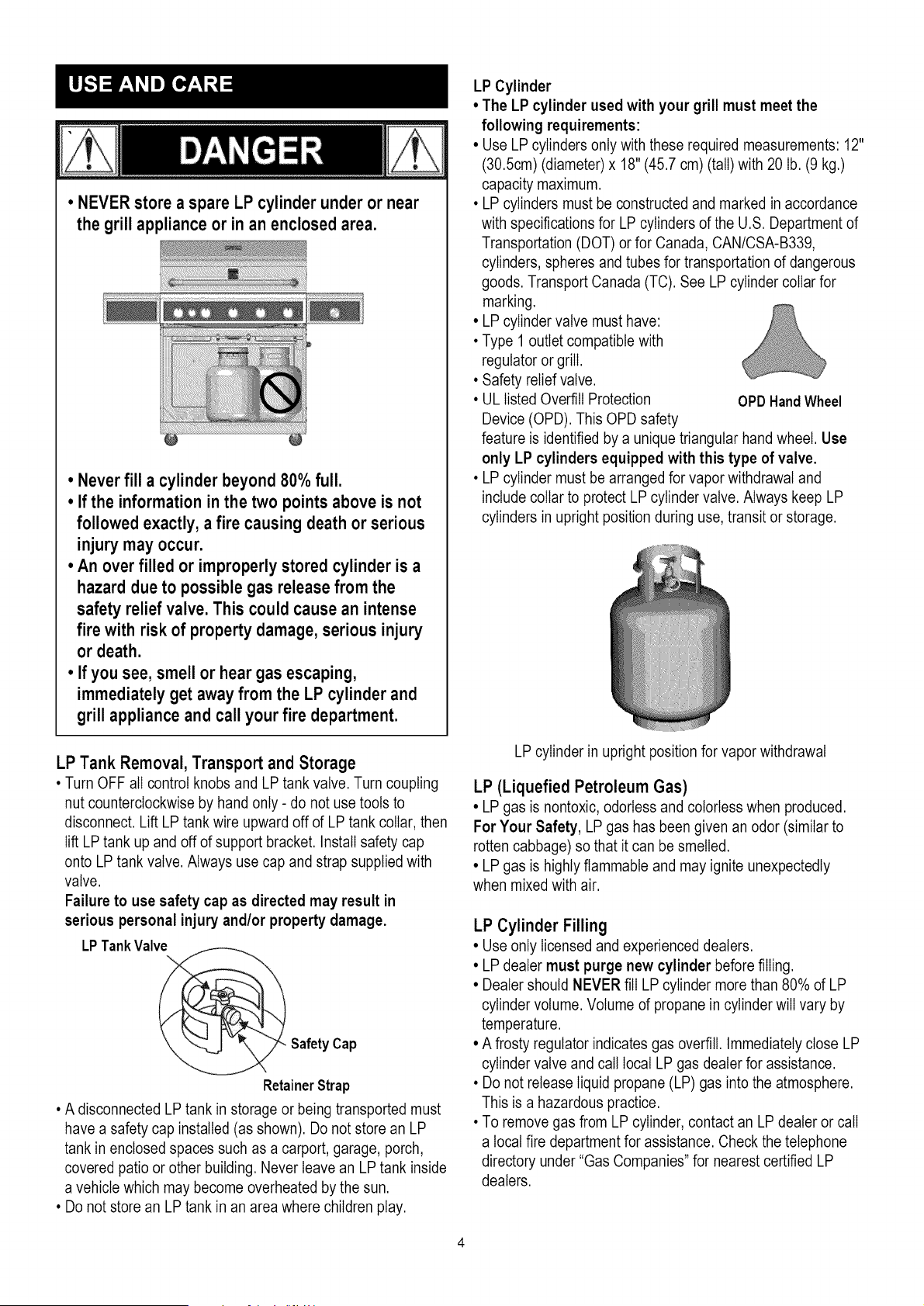
• NEVER store a spare LP cylinder under or near
the grill appliance or in an enclosed area.
• Never fill a cylinder beyond 80% full.
• If the information in the two points above is not
followed exactly, a fire causing death or serious
injury may occur.
• An over filled or improperly stored cylinder is a
hazard due to possible gas release from the
safety relief valve. This could cause an intense
fire with risk of property damage, serious injury
or death.
° If you see, smell or hear gas escaping,
immediatelyget away from the LP cylinder and
grill appliance and call your fire department.
LP Cylinder
• The LP cylinder used with your grill must meet the
following requirements:
• Use LP cylinders only with these required measurements: 12"
(30.5cm) (diameter) x 18" (45.7 cm) (tall) with 20 lb. (9 kg.)
capacity maximum.
• LP cylinders must be constructed and marked in accordance
with specifications for LP cylinders of the U.S. Department of
Transportation (DOT) or for Canada, CAN/CSA-B339,
cylinders, spheres and tubes for transportation of dangerous
goods. Transport Canada (TC). See LP cylinder collar for
marking.
• LP cylinder valve must have:
• Type 1 outlet compatible with
regulator or grill.
• Safety relief valve.
• UL listed Overfill Protection OPD HandWheel
Device (OPD). This OPD safety
feature is identified by a unique triangular hand wheel. Use
only LP cylinders equipped with this type of valve.
• LP cylinder must be arranged for vapor withdrawal and
include collar to protect LP cylinder valve. Always keep LP
cylinders in upright position during use, transit or storage.
LP Tank Removal, Transport and Storage
• Turn OFF all control knobs and LP tank valve. Turn coupling
nut counterclockwise by hand only - do not use tools to
disconnect. Lift LP tank wire upward off of LP tank collar, then
lift LP tank up and off of support bracket. Install safety cap
onto LP tank valve. Always use cap and strap supplied with
valve.
Failure to use safety cap as directed may result in
serious personal injury and/or property damage.
LPTankValve
@_ Safety Cap
RetainerStrap
• A disconnected LP tank in storage or being transported must
have a safety cap installed (as shown). Do not store an LP
tank in enclosed spaces such as a carport, garage, porch,
covered patio or other building. Never leave an LP tank inside
a vehicle which may become overheated by the sun.
• Do not store an LP tank in an area where children play.
LP cylinder in upright position for vapor withdrawal
LP (Liquefied Petroleum Gas)
• LP gas is nontoxic, odorless and colorless when produced.
For Your Safety, LP gas has been given an odor (similar to
rotten cabbage) so that it can be smelled.
• LP gas is highly flammable and may ignite unexpectedly
when mixed with air.
LP Cylinder Filling
• Use only licensed and experienced dealers.
• LP dealer must purge new cylinder before filling.
• Dealer should NEVER fill LP cylinder more than 80% of LP
cylinder volume. Volume of propane in cylinder will vary by
temperature.
• A frosty regulator indicates gas overfill. Immediately close LP
cylinder valve and call local LP gas dealer for assistance.
• Do not release liquid propane (LP) gas into the atmosphere.
This is a hazardous practice.
• To remove gas from LP cylinder, contact an LP dealer or call
a local fire department for assistance. Check the telephone
directory under "Gas Companies" for nearest certified LP
dealers.
LP Tank Exchange
•Many retailers that sell grills offer you the option of replacing
your empty LP tank through an exchange service. Use only
those reputable exchange companies that inspect, precision
fill, test and certify their cylinders. Exchange your tank only
for an OPD safety feature-equipped tank as described in
the "LP Tank" section of this manual.
•Always keep new and exchanged LP tanks in upright position
during use, transit or storage.
,Leak test new and exchanged LP tanks BEFORE
connecting to grill.
LP Tank Leak Test
Foryoursafety
•Leak test must be repeated each time LP tank is exchanged
or refilled.
•Do not smoke during leak test.
•Do not use an open flame to check for gas leaks.
•Grill must be leak tested outdoors in a well-ventilated area,
away from ignition sources such as gas fired or electrical
appliances. During leak test, keep grill away from open
flames or sparks.
•Use a clean paintbrush and a 50/50 mild soap and water
solution. Brush soapy solution onto areas indicated by arrows
in figure below. Leaks are indicated by growing bubbles.
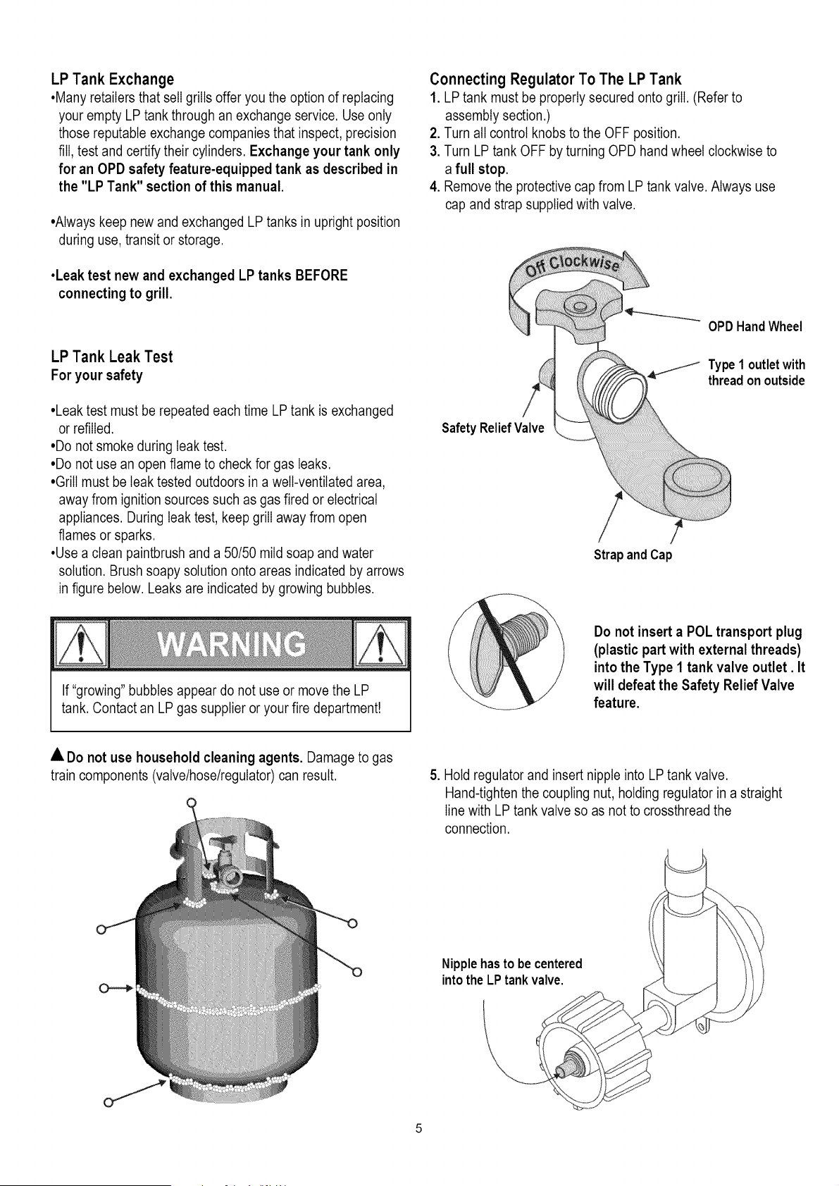
Connecting Regulator To The LP Tank
1. LP tank must be properly secured onto grill. (Refer to
assembly section.)
2. Turn all control knobs to the OFF position.
3. Turn LP tank OFF by turning OPD hand wheel clockwise to
a full stop.
4. Remove the protective cap from LP tank valve. Always use
cap and strap supplied with valve.
OPDHand Wheel
.I./I Type1outletwith
threadon outside
Safety ReliefValve
Strap andCap
If "growing" bubbles appear do not use or move the LP
tank. Contact an LP gas supplier or your fire department!
Do not insert a POL transport plug
(plastic part with external threads)
into the Type 1 tank valve outlet. It
will defeat the Safety Relief Valve
feature.
• Do not use household cleaning agents. Damage to gas
train components (valve/hose/regulator) can result.
5. Hold regulator and insert nipple into LP tank valve.
Hand-tighten the coupling nut, holding regulator in a straight
line with LP tank valve so as not to crossthread the
connection.
Nipplehasto be centered
into the LP tank valve.
J
S
s
,f
J
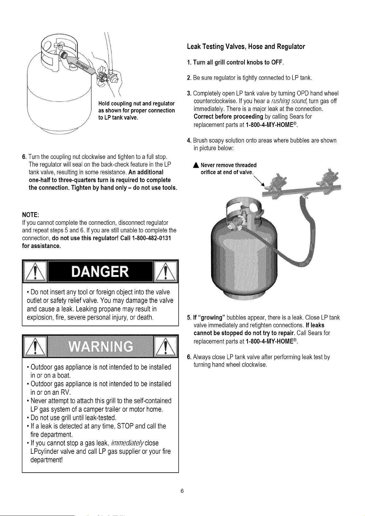
Holdcouplingnut andregulator
asshownfor properconnection
to LP tankvalve.
6. Turn the coupling nut clockwise and tighten to a full stop.
The regulator will seat on the back-check feature in the LP
tank valve, resulting in some resistance. An additional
one-half to three-quarters turn is required to complete
the connection. Tighten by hand only - do not use tools.
Leak Testing Valves, Hose and Regulator
1. Turnall grillcontrolknobsto OFF.
2. Be sure regulator is tightly connected to LP tank.
.
Completely open LP tank valve by turning OPD hand wheel
counterclockwise. If you hear a rushing sound, turn gas off
immediately. There is a major leak at the connection.
Correct before proceeding by calling Sears for
replacement parts at 1-800-4-MY-HOME®.
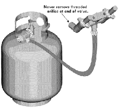
4. Brush soapy solution onto areas where bubbles are shown
in picture below:
• Neverremovethreaded
orificeatend of valve.
NOTE:
If you cannot complete the connection, disconnect regulator
and repeat steps 5 and 6. If you are still unable to complete the
connection, do not use this regulatod Call 1-800-482-0131
for assistance.
• Do not insert any tool or foreign object into the valve
outlet or safety relief valve. You may damage the valve
and cause a leak. Leaking propane may result in
explosion,fire, severe personal injury, or death.
• Outdoor gas appliance is not intended to be installed
in or on a boat.
• Outdoor gas appliance is not intended to be installed
in or on an RV.
• Never attempt to attach this grill to the self-contained
LP gas system of a camper trailer or motor home.
• Do not use grill until leak-tested.
• If a leak is detected at any time, STOP and call the
fire department.
• If you cannot stop a gas leak, immediate/yclose
LPcylinder valve and call LP gas supplier or your fire
department!
5. If "growing" bubbles appear, there is a leak. Close LP tank
valve immediately and retighten connections. If leaks
cannot be stopped do not try to repair. Call Sears for
replacement parts at 1-800-4-MY-HOME®.
6. Always close LP tank valve after performing leak test by
turning hand wheel clockwise.
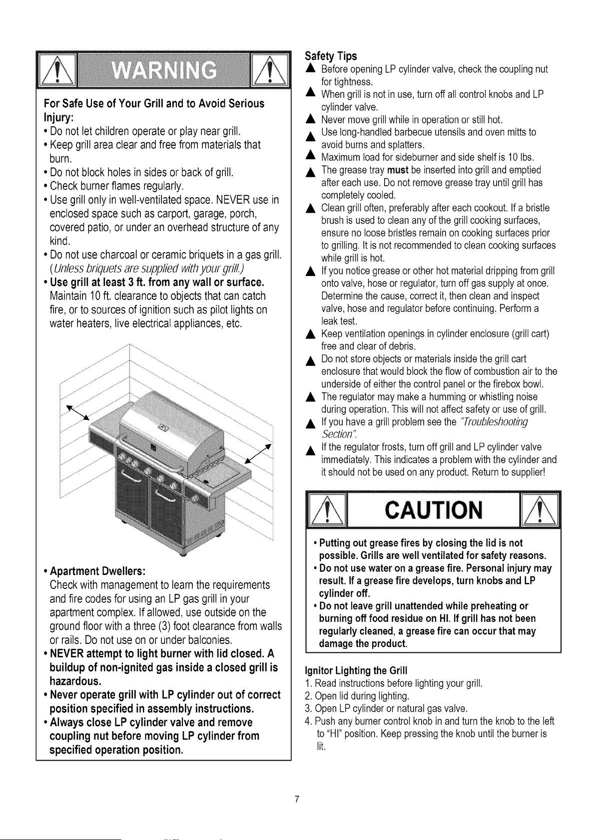
For Safe Use of Your Grill and to Avoid Serious
Injury:
• Do not let children operate or play neargrill.
• Keep grill area clear and free from materials that
burn.
• Do not block holes in sides or back of grill.
• Check burnerflames regularly.
• Use grill only in well-ventilated space. NEVER use in
enclosedspace such as carport, garage, porch,
covered patio, or under an overhead structure of any
kind.
• Do not use charcoal or ceramic briquets in a gas grill.
(Unless briquets are supplied withyour grill.)
• Use grill at least 3 ft. from any wall or surface.
Maintain 10 ft. clearance to objects that can catch
fire, or to sources of ignition such as pilot lights on
water heaters, live electrical appliances, etc.
• Apartment Dwellers:
Check with managementto learn the requirements
and fire codes for using an LP gas grill in your
apartment complex. If allowed, use outside on the
ground floor with a three (3) foot clearance from walls
or rails. Do not use on or under balconies.
° NEVER attempt to light burner with lid closed. A
buildup of non-ignited gas inside a closed grill is
hazardous.
• Never operate grill with LP cylinder out of correct
position specified in assembly instructions.
• Always close LP cylinder valve and remove
coupling nut before moving LP cylinder from
specified operation position.
Safety Tips
• Before opening LP cylinder valve, check the coupling nut
for tightness.
• When grill is not in use, turn off all control knobs and LP
cylinder valve.
• Never move grill while in operation or still hot.
• Use long-handled barbecue utensils and oven mitts to
avoid burns and splatters.
• Maximum load for sideburner and side shelf is 10 Ibs.
• The grease tray must be inserted into grill and emptied
after each use. Do not remove grease tray until grill has
completely cooled.
• Clean grill often, preferably after each cookout. If a bristle
brush is used to clean any of the grill cooking surfaces,
ensure no loose bristles remain on cooking surfaces prior
to grilling. It is not recommended to clean cooking surfaces
while grill is hot.
• If you notice grease or other hot material dripping from grill
onto valve, hose or regulator, turn off gas supply at once.
Determine the cause, correct it, then clean and inspect
valve, hose and regulator before continuing. Perform a
leak test.
• Keep ventilation openings in cylinder enclosure (grill cart)
free and clear of debris.
• Do not store objects or materials inside the grill cart
enclosure that would block the flow of combustion air to the
underside of either the control panel or the firebox bowl.
• The regulator may make a humming or whistling noise
during operation. This will not affect safety or use of grill.
• If you have a grill problem see the "Troubleshooting
Section".
• If the regulator frosts, turn off grill and LP cylinder valve
immediately. This indicates a problem with the cylinder and
it should not be used on any product. Return to supplier!
CAUTION
• Putting out grease fires by closing the lid is not
possible. Grills are well ventilated for safety reasons.
• Do not use water on a grease fire. Personal injury may
result. If a grease fire develops, turn knobs and LP
cylinder off.
• Do not leave grill unattended while preheating or
burning off food residue on HI. If grill has not been
regularly cleaned, a grease fire can occur that may
damage the product.
Ignitor Lighting the Grill
1. Read instructions before lighting your grill.
2. Open lid during lighting.
3. Open LP cylinder or natural gas valve.
4. Push any burner control knob in and turn the knob to the left
to "HI" position. Keep pressing the knob until the burner is
lit.
5.Ifignitiondoesnotoccurin5seconds,turntheburner
controloff,wait5minutesforgastoclearaway,andrepeat
thelightingprocedure.
6.Tolightotherburners,repeatstep4.
NOTE:Ifignitordoesnotwork,followMatchLighting
instructions.
Turn controls and gas source or tank OFF when
not in use.
If ignitiondoesnot occurin5 seconds,turnthe burner
controloff,wait5 minutes,and repeatthe lighting
procedure.If the burner does not ignite with
the valve open, gas will continue to flow out of the
burner and could accidently ignite with risk of
injury.
Match-Lighting
• Do not lean over grill while lighting.
1. Open lid during lighting.
2. Place match into match holder (hanging from side of cart).
Light match, place into the firebox.
3. Push in and turn right knob to HIGH position. Be sure burner
lights and stays lit.
4. Light other burners by pushing knob in and turning to HI
position.
Sideburner Match Lighting
1. Open sideburner lid. Turn on gas at LP cylinder.
2. Place Iit match near burner.
3.Turn sideburner knob to HI. Be sure burner lights and
stays lit.
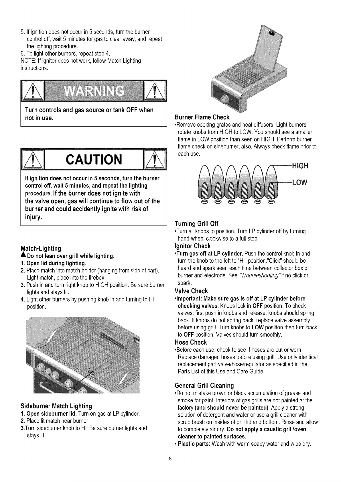
Burner Flame Check
,Remove cooking grates and heat diffusers. Light burners,
rotate knobs from HIGH to LOW. You should see a smaller
flame in LOW position than seen on HIGH. Perform burner
flame check on sideburner, also. Always check flame prior to
each use.
3H
Turning GrillOff
•Turn all knobs to position. Turn LP cylinder off by turning
hand-wheel clockwise to a full stop.
Ignitor Check
•Turn gas off at LP cylinder. Push the control knob in and
turn the knob to the left to "HI" position?Click" should be
heard and spark seen each time between collector box or
burner and electrode. See "Troub/eshooting"if no click or
spark.
Valve Check
•Important: Make sure gas is off at LP cylinder before
checking valves. Knobs lock in OFF position. To check
valves, first push in knobs and release, knobs should spring
back. If knobs do not spring back, replace valve assembly
before using grill. Turn knobs to LOW position then turn back
to OFF position. Valves should turn smoothly.
Hose Check
•Before each use, check to see if hoses are cut or worn.
Replace damaged hoses before using grill. Use only identical
replacement part valve/hose/regulator as specified in the
Parts List of this Use and Care Guide.
General Grill Cleaning
•Do not mistake brown or black accumulation of grease and
smoke for paint. Interiors of gas grills are not painted at the
factory (and should never be painted). Apply a strong
solution of detergent and water or use a grill cleaner with
scrub brush on insides of grill lid and bottom. Rinse and allow
to completely air dry. Do not apply a caustic grill/oven
cleaner to painted surfaces.
• Plastic parts: Wash with warm soapy water and wipe dry.
Donotusecitrisot,abrasivecleaners,degreasersora
concentratedgrillcleaneronplasticparts.Damagetoand
failureofpartscanresult.
•Porcelainsurfaces:Becauseofglass-likecomposition,most
residuecanbewipedawaywithbakingsoda/watersolutionor
speciallyformulatedcleaner.Usenonabrasivescouring
powderforstubbornstains.
*Painted surfaces: Wash with mild detergent or nonabrasive
cleaner and warm soapy water. Wipe dry with a soft
nonabrasive cloth.
•Stainless steel surfaces: To maintain your grill's high quality
appearance, wash with mild detergent and warm soapy water
and wipe dry with a soft cloth after each use. Baked-on
grease deposits may require the use of an abrasive plastic
cleaning pad. Use only in direction of brushed finish to avoid
damage. Do not use abrasive pad on areas with graphics.
• Cooking surfaces: If a bristle brush is used to clean any of
the grill cooking surfaces, ensure no loose bristles remain on
cooking surfaces prior to grilling. It is not recommended to
clean cooking surfaces while grill is hot.
Storing Your Grill
•Clean cooking grates.
•Store in dry location.
•When LP cylinder is connected to grill, store outdoors in a
wellventilated space and out of reach of children.
•Cover grill if stored outdoors. Choose from a variety of grill
covers offered by manufacturer.
•Store grill indoors ONLY if LP cylinder is turned off and
disconnected, removed from grill and stored outdoors.
•When removing grill from storage, follow "Cleaning the Burner
Assemb/7 instructions before starting grill
Cleaning the Burner Assembly
Follow these instructions to clean and/or replace parts of
burner assembly or if you have trouble igniting grill.
1. Turn gas off at control knobs and LP cylinder.
2. Remove cooking grates and heat diffusers.
3. Remove R pins from rear of burners.
4. Carefully lift each burner up and away from valve openings.
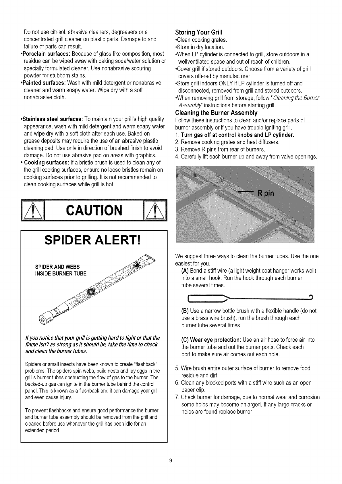
SPIDER ALERT!
SPIDERANDWEBS
Ifyou notice thatyour grill is getting hard to light or that the
flame isn't as strong as it should be, take the time to check
and clean the burner tubes.
Spidersor smallinsectshave beenknownto create"flashback"
problems.Thespidersspinwebs,buildnestsandlay eggsin the
grill's burnertubesobstructingtheflow of gasto the burner.The
backed-upgascan igniteinthe burnertube behindthe control
panel.This is knownas a flashbackandit candamageyour grill
andevencauseinjury.
To preventflashbacksandensuregoodperformancethe burner
and burnertubeassemblyshouldbe removedfrom the grilland
cleanedbeforeusewheneverthe grill has beenidlefor an
extendedperiod.
We suggest three ways to clean the burner tubes. Use the one
easiest for you.
(A) Bend a stiff wire (a light weight coat hanger works well)
into a small hook. Run the hook through each burner
tube several times.
(B) Use a narrow bottle brush with a flexible handle (do not
use a brass wire brush), run the brush through each
burner tube several times.
(C) Wear eye protection: Use an air hose to force air into
the burner tube and out the burner ports. Check each
port to make sure air comes out each hole.
5. Wire brush entire outer surface of burner to remove food
residue and dirt.
6. Clean any blocked ports with a stiff wire such as an open
paper clip.
7. Check burner for damage, due to normal wear and corrosion
some holes may become enlarged. If any large cracks or
holes are found replace burner.
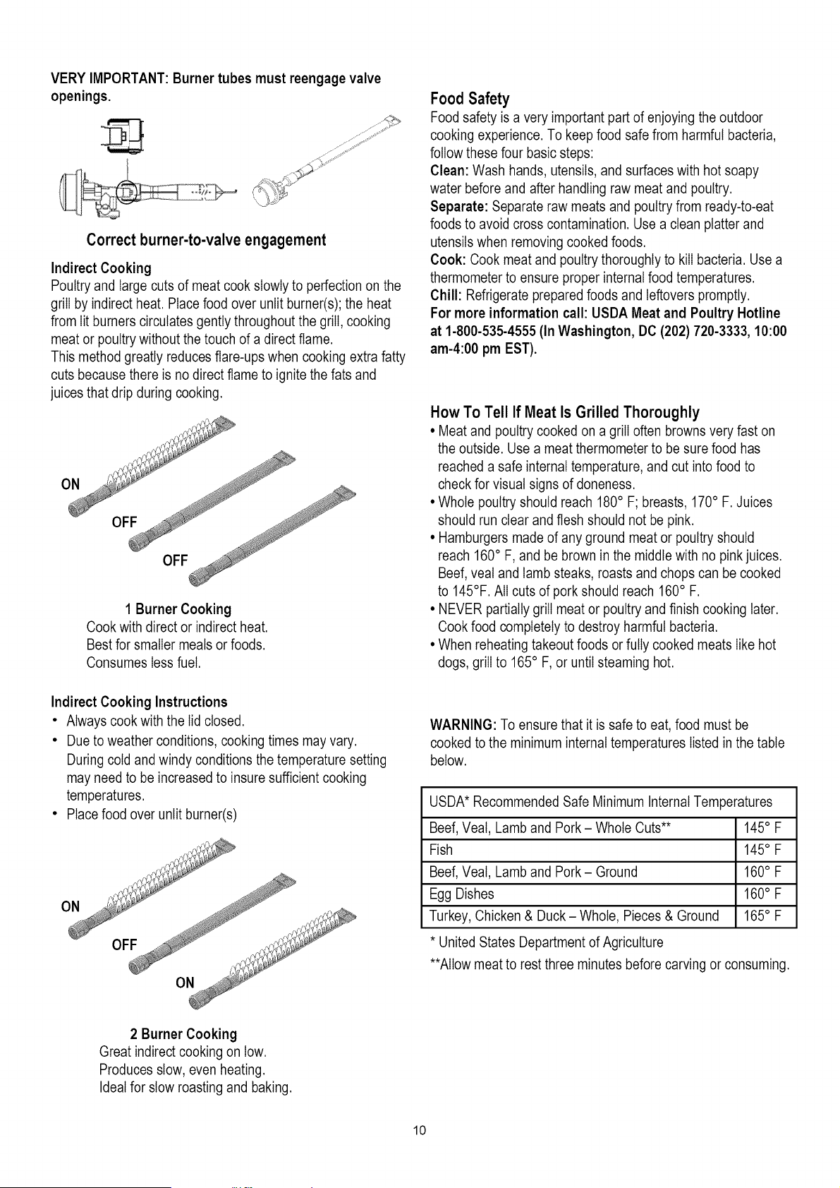
VERY IMPORTANT: Burner tubes must reengage valve
openings.
Correct burner-to-valve engagement
Indirect Cooking
Poultry and large cuts of meat cook slowly to perfection on the
grill by indirect heat. Place food over unlit burner(s); the heat
from lit burners circulates gently throughout the grill, cooking
meat or poultry without the touch of a direct flame.
This method greatly reduces flare-ups when cooking extra fatty
cuts because there is no direct flame to ignite the fats and
juices that drip during cooking.
1 Burner Cooking
Cook with direct or indirect heat.
Best for smaller meals or foods.
Consumes less fuel.
Indirect Cooking Instructions
• Always cook with the lid closed.
• Due to weather conditions, cooking times may vary.
During cold and windy conditions the temperature setting
may need to be increased to insure sufficient cooking
temperatures.
• Place food over unlit burner(s)
Food Safety
Food safety is a very important part of enjoying the outdoor
cooking experience. To keep food safe from harmful bacteria,
follow these four basic steps:
Clean: Wash hands, utensils, and surfaces with hot soapy
water before and after handling raw meat and poultry.
Separate: Separate raw meats and poultry from ready-to-eat
foods to avoid cross contamination. Use a clean platter and
utensils when removing cooked foods.
Cook: Cook meat and poultry thoroughly to kill bacteria. Use a
thermometer to ensure proper internal food temperatures.
Chill: Refrigerate prepared foods and leftovers promptly.
For more information call: USDA Meat and Poultry Hotline
at 1-800-535-4555 (In Washington, DC (202) 720-3333, 10:00
am-4:00 pm EST).
How To Tell If Meat Is Grilled Thoroughly
• Meat and poultry cooked on a grill often browns very fast on
the outside. Use a meat thermometer to be sure food has
reached a safe internal temperature, and cut into food to
check for visual signs of aloneness.
• Whole poultry should reach 180° F; breasts, 170° F. Juices
should run clear and flesh should not be pink.
• Hamburgers made of any ground meat or poultry should
reach 160° F, and be brown in the middle with no pink juices.
Beef,veal and lamb steaks, roasts and chops can be cooked
to 145°F. All cuts of pork should reach 160° F.
• NEVER partially grill meat or poultry and finish cooking later.
Cook food completely to destroy harmful bacteria.
• When reheating takeout foods or fully cooked meats like hot
dogs, grill to 165° F, or until steaming hot.
WARNING: To ensure that it is safe to eat, food must be
cooked to the minimum internal temperatures listed in the table
below.
USDA* Recommended Safe Minimum Internal Temperatures
Beef, Veal, Lamb and Pork - Whole Cuts** 145° F
Fish 145° F
Beef, Veal, Lamb and Pork - Ground 160° F
Egg Dishes 160° F
Turkey, Chicken & Duck- Whole, Pieces & Ground 165° F
* United States Department of Agriculture
**Allow meat to rest three minutes before carving or consuming.
2 Burner Cooking
Great indirect cooking on tow.
Produces slow, even heating.
Ideal for slow roasting and baking.
10
Gas Requirements
LP Gas
If your grill is for LP Gas, the regulator supplied is set for
an 11-in.water column (WC) and is for use with LP gas
only.The factory-supplied regulator and hose must be
used with a 20-lb. LP gas tank.
Excess Flow Control and Low Heat
The propane regulator assembly incorporates an excess
flow device designed to supply the grill with sufficient gas
flow under normal conditions yet control excess gas flow.
Rapid changes in pressure can trigger the excessflow
device providing a low flame and low temperature. If the
tank valve is turned open to allow gas flow while a burner
valve is open, the surge of pressurewill cause the device
to activate. The device will remain closed until the
pressure is equalized. This should occur within 5
seconds.
To ensure this does not cause difficulty in lighting the grill,
follow these instructions:
1. Make sure all burner valves are "OFF".
2. Open the tank valve and wait 5 seconds.
3. Light the burners one at a time following the lighting
instructions.
Helpful Care and Maintenance Hints
Before grilling, pre-heat grill for 15 minutes on "HI" with
hood down. To avoid uncontrolled flare-ups or grease
fires, grill meats with hood open. Close hood if meats are
thick or weather is cold, or if you are using a rotisserie or
indirect cooking.
Always protect your hand with a pot holder or cooking
glove when coming into contact with a hot surface.
Hood up when grilling meats, especiallychicken. Hood
down when indirect or rotisserie cooking.
NEVER leave your grill unattendedwhile cooking.
After use, close hood, turn burnersto HI for 15 min. for
self-cleaning,grease burn off.
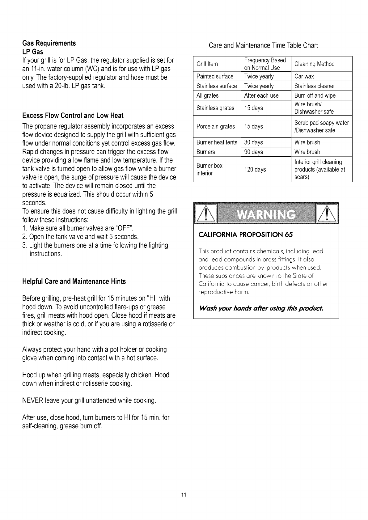
Care and MaintenanceTime TableChart
Grill Item FrequencyBased
on Normal Use Cleaning Method
Paintedsurface Twiceyearly Car wax
Stainlesssurface Twiceyearly Stainlesscleaner
All grates Aftereach use Burn offand wipe
Wire brush/
Stainlessgrates 15days Dishwashersafe
Porcelaingrates 15days Scrub padsoapy water
/Dishwashersafe
Burnerheat tents 30 days Wire brush
Burners 90 days Wire brush
Burnerbox Interiorgrill cleaning
120days products(available at
interior sears)
CALIFORNIA PROPOSITION 65
This product contains chemicals, including lead
and lead compounds in brass fittings. It also
produces combustion by-products when used.
These substances are known to the State of
California to cause cancer, birth defects or other
reproductive harm.
Wash your hands after using this product.
11
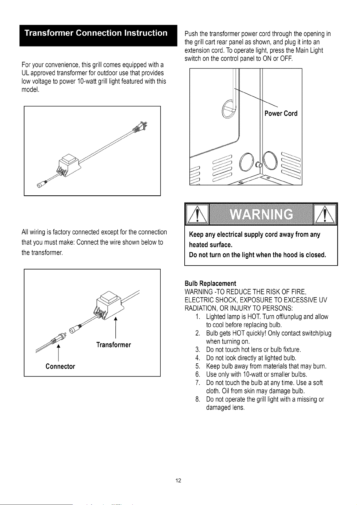
For your convenience, this grill comes equipped with a
UL approved transformerfor outdoor use that provides
low voltage to power 10-wattgrill light featured with this
model.
Push the transformer power cord through the opening in
the grill cart rear panel as shown, and plug it into an
extension cord. To operate light, press the Main Light
switch on the control panel to ON or OFF.
Power Cord
All wiring is factory connected except for the connection
that you must make: Connect the wire shown below to
the transformer.
Keep any electrical supply cord away from any
heated surface.
Do not turn on the light when the hood is closed.
t
Transformer
Connector
Bulb Replacement
WARNING -TO REDUCE THE RISK OF FIRE,
ELECTRIC SHOCK, EXPOSURE TO EXCESSIVE UV
RADIATION,OR INJURYTO PERSONS:
1. Lightedlamp is HOT.Turn off/unplug and allow
to cool before replacing bulb.
2. Bulb gets HOTquickly! Only contact switch/plug
when turning on.
3. Do not touch hot lens or bulb fixture.
4. Do not look directly at lighted bulb.
5. Keep bulb away from materials that may burn.
6. Use only with 10-watt or smaller bulbs.
7. Do not touch the bulb at any time. Use a soft
cloth. Oil from skin may damage bulb.
8. Do not operate the grill light with a missing or
damaged lens.
12
.
.
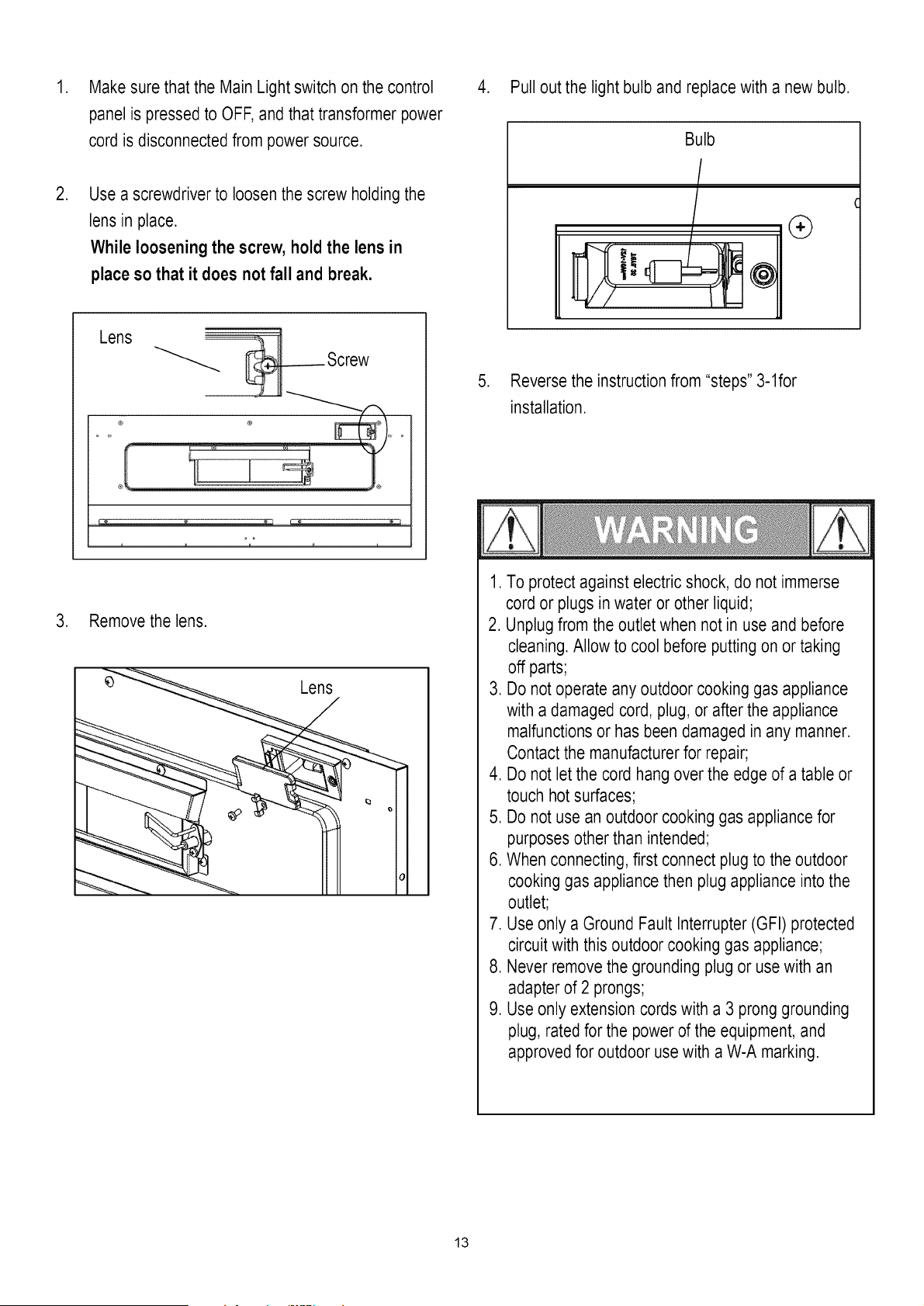
Make sure that the Main Light switch on the control
panel is pressedto OFF, and that transformer power
cord is disconnectedfrom power source.
Use a screwdriver to loosen the screw holding the
lens in place.
While loosening the screw, hold the lens in
place so that it does not fall and break.
Lens ..........
® ® ,_
®
3. Remove the lens.
4. Pull out the light bulb and replace with a new bulb.
.
Bulb
(
(9
Reverse the instruction from "steps" 3-1for
installation.
1. To protect against electricshock, do not immerse
cord or plugs in water or other liquid;
2. Unplug from the outlet when not in use and before
cleaning. Allow to cool before putting on or taking
off parts;
3. Do not operate any outdoor cooking gas appliance
with a damaged cord, plug, or after the appliance
malfunctionsor has been damaged in any manner.
Contact the manufacturer for repair;
4. Do not let the cord hang over the edge of a table or
touch hotsurfaces;
5. Do not use an outdoor cooking gas appliance for
purposesother than intended;
6. When connecting, first connect plug to the outdoor
cooking gas appliance then plug appliance into the
outlet;
7. Use only a Ground Fault Interrupter (GFI) protected
circuit with this outdoor cooking gas appliance;
8. Never remove the grounding plug or usewith an
adapter of 2 prongs;
9. Use only extension cords with a 3 prong grounding
plug, rated for the power of the equipment, and
approved for outdoor use with a W-A marking.
13
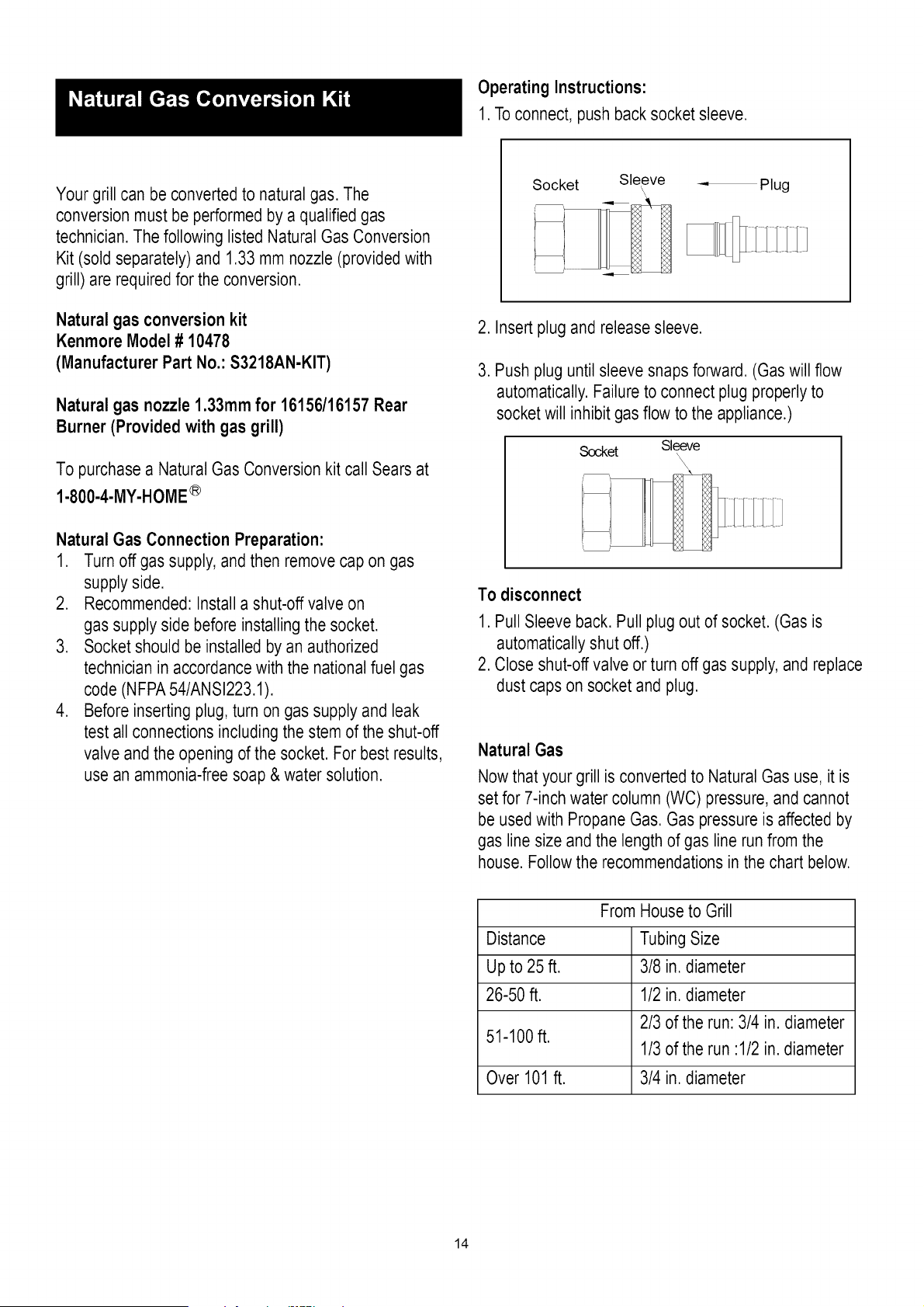
Operating Instructions:
1. To connect, push back socket sleeve.
Your grill can be converted to natural gas. The
conversion must be performed by a qualified gas
technician.The following listed Natural Gas Conversion
Kit (sold separately) and 1.33 mm nozzle (provided with
grill) are required for the conversion.
Natural gas conversion kit
Kenmore Model# 10478
(Manufacturer Part No.: S3218AN-KIT)
Naturalgasnozzle1.33rnrnfor 16156/16157Rear
Burner (Providedwith gasgrill)
To purchase a Natural Gas Conversion kit call Sears at
1.800.4.MY.HOME ®
Natural Gas Connection Preparation:
1. Turn off gas supply, and then remove cap on gas
supply side.
2. Recommended: Install a shut-off valve on
gas supply side before installing the socket.
3. Socket should be installed by an authorized
technician in accordance with the nationalfuel gas
code (NFPA54/ANSI223.1).
4. Before inserting plug, turn on gas supply and leak
test all connections including the stem of the shut-off
valve and the opening of the socket. For best results,
use an ammonia-free soap & water solution.
Socket Sleeve_ _- Plug
2. Insert plug and release sleeve.
3. Push plug until sleeve snaps forward. (Gas will flow
automatically.Failure to connect plug properly to
socket will inhibit gas flow to the appliance.)
Socket Sleeve
To disconnect
1. Pull Sleeve back. Pull plug out of socket. (Gas is
automaticallyshut off.)
2. Close shut-off valve or turn off gas supply, and replace
dust caps on socket and plug.
Natural Gas
Now that your grill is converted to Natural Gas use, it is
set for 7-inch water column (WC) pressure, and cannot
be used with Propane Gas. Gas pressure is affected by
gas line size and the length of gas line run from the
house. Follow the recommendations in the chart below.
From House to Grill
Distance Tubing Size
Up to 25 ft. 3/8 in. diameter
26-50 ft. 1/2 in. diameter
2/3 of the run: 3/4 in. diameter
51-100 ft.
1/3of the run :1/2 in. diameter
Over 101 ft. 3/4 in. diameter
14
Key
1
2
3
4
5
6
7
8
9
I0
11
12
13
14
15
16
17-1
17-2
18
19
2O
21
22
23
24
25
26
27
28
29
3O
31-I
31-2
32
33
34
35
36
37
38
39
4O
41
42
Qty
1
2
I
I
I
5
3
I
5
5
1
1
1
1
1
2
I
I
2
2
I
I
I
I
I
I
I
1
1
1
I
1
I
I
I
I
I
I
I
6
6
I
I
I
Description
HOOD HANDLE
HANDLE BASE
HOOD
TEMPERATURE GAUGE
WASHER
R-PIN
COOKING GRID ( MAIN BURNER )
WARMING RACK
HEAT DIFFUSER
MAIN BURNER
IGNITION PIN ( MAIN BURNER )
IGNITION PIN ( MAIN BURNER )
IGNITION PIN ( MAIN BURNER )
IGNITION PIN ( MAIN BURNER )
IGNITION PIN ( MAIN BURNER )
RUBBER PLUG
SIDE SHELF (BLACK)
SIDE SHELF (RED)
5/16-18 UNC x 1"
HOOD SLEEVE
BURNER BOX
REAR BURNER HOSE
REAR BURNER
REAR HOOD
LAMP SCREEN (LENS)
BULB
IGNITION PIN ( REAR BURNER )
SIDE HOOD HANDLE
SIDE HOOD
SIDE BURNER GRID
SIDE BURNER SHAFT
SIDE BURNER SHELF (BLACK)
SIDE BURNER SHELF (RED)
SIDE BURNER
SIDE DRIP TRAY
SIDE BURNER ORIFICE
SIDE BURNER HOSE
IGNITION PiN ( SIDE BURNER )
SIDE BURNER VALVE
BEZEL
KNOB
LP GAS PRESSURE REGULATOR
MAIN BURNER HOSE
MANIFOLD
Manufacturer
Part #
3218LT-00-4300
S3218ANR-O0-4001
S3218ANR-90-4109
2818-2T-A300
E3518-00-4099
GB/T 91-2009
L3218-90-2010
S3218ANR-O0-2026
2518SL-2003-N
SH3118B-2004
P3018-06-8003
P3018-06-8004
P3018-06-8005
P3018-06-8006
L3218-90-8907
3219B-8082
S3218ANB-90-5009
S3218ANR-O0-5090
SCREW& NUT
E3518-00-0001
S3218ANR-O0-2009
P3018-00-8015
S3218ANR-06-8030
S3218ANR-O0-2426
E3520-06-8017
L3218-06-8021
S3218ANR-06-8008
3218LT-00-2864
3218LT-90-2802
3218LT-00-2840
3218LTN-90-2802
S3218ANB-90-6100
S3218ANR-06-6190
P3018-00-8068
P3018-90-6010
P3018-O0-8068-A
S3218AR-90-8905
S3218ANR-O0-8069
S3218AR-90-6600
E3518-00-3062
E3518-00-3061
L3218-06-8006
P3018-00-8021
S3218ANR-90-3206
Key Qty Description
43 1 SWITCH
44 I REAR BURNER BEZEL
45 I REAR BURNER KNOB
46 1 IGNITION WIRE
47-1 1 CONTROL BOX (BLACK)
47-2 1 CONTROL BOX (RED)
48 I BEAM
49 I DRIP TRAY
50 I DRIP TRAY SUPPORT
51 1 TANK RING
52 I TANK RING BRACKET
53 I REAR PANEL
54 1 HAND IGNITOR
55 I TRANSFORMER
56 I RIGHT PANEL
57 I IGNITER PROTECTIVE BOX
58 I SIDE PANEL BRACKET (RIGHT)
59 I IGNITER
60 2 LOCKING CASTER
61 I BOTTOM PANEL
62 2 CASTER
63 2 MAGNET
64 2 TANK STOPPER
65-1 1 RIGHT DOOR (BLACK)
65-2 1 RIGHT DOOR (RED)
66 2 DOOR HANDLE
67-1 1 LEFT DOOR (BLACK)
67-2 1 LEFT DOOR (RED)
68 I SIDE PANEL BRACKET (LEFT)
69 I LEFT PANEL
1 HARDWARE PACK
1 PRODUCT MANUAL
REAR BURNER NG NOZZLE PACKAGE
Manufacturer
Part#
E3520-00-8015
L3218-90-3902
L3218-06-3901
S3218ANR-O0-8061
S3218ANB-90-3101
S3218ANR-90-3101
S3218AR-90-1500
P3918-90-1002
S3218ANR-90-1906
P3018-00-1293
E3518-00-1262
S3218ANR-06-1290
3919L-1719
S3218ANR-O0-8023
S3218ANR-90-1806
S3218ANR-O0-1862
L3018S-90-1920
S3218ANR-O0-8011
3218LTN-06-8013
S3218ANR-O0-1110
3218LTN-90-8912
L3018S-06-1310
E3520-00-1050
S3218ANB-90-1600
S3218ANR-O0-1690
L3018S-06-1410
S3218ANB-90-1409
S3218ANR-O0-1400
L3018S-90-1910
S3218ANR-O0-1790
S3218AN-
HARDWARE
S3218AN-
MANUAL
S3218AN-REAR
BURNER NOZZLE
-PACK
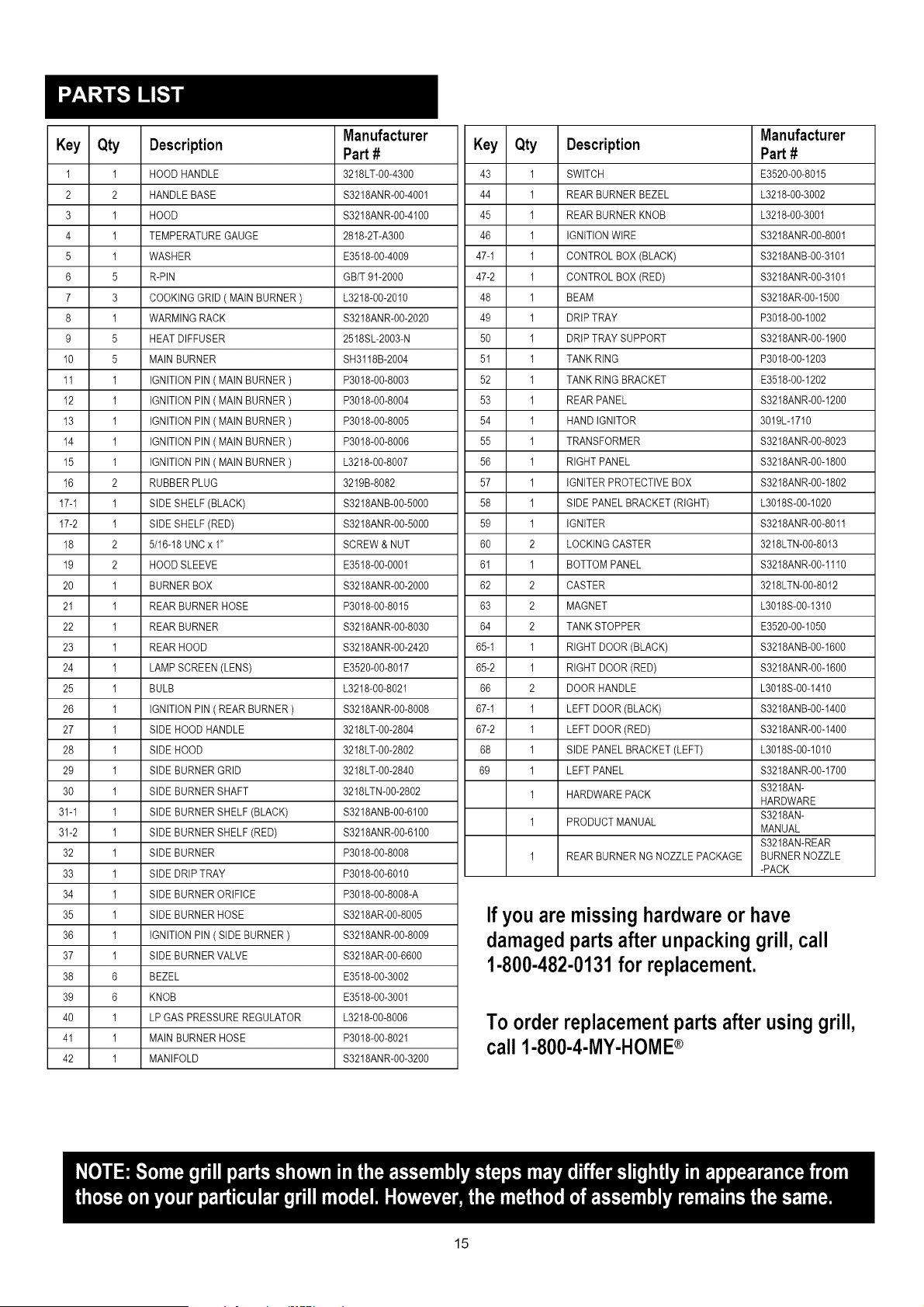
If you are missinghardwareor have
damagedparts after unpackinggrill, call
1-800-482-0131for replacement.
To order replacementparts after using grill,
call 1-800-4-MY-HOME®
15
@ @ @
/
®
®@@
@
S
@
@ @
@
@
16
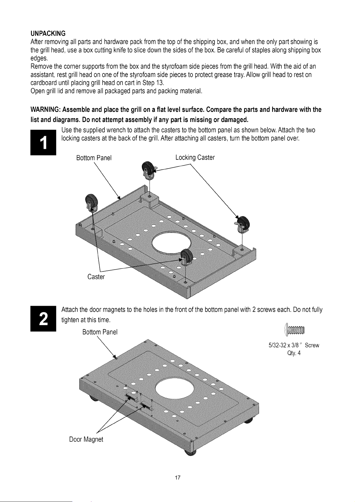
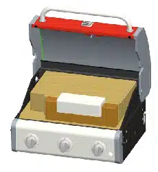
UNPACKING
After removing all parts and hardware pack from the top of the shipping box, and when the only part showing is
the grill head, use a box cutting knife to slice down the sides of the box. Be careful of staples along shipping box
edges.
Remove the corner supports from the box and the styrofoam side piecesfrom the grill head. With the aid of an
assistant, rest grill head on one of the styrofoam side pieces to protect grease tray.Allow grill head to rest on
cardboard until placing grill head on cart in Step 13.
Open grill lid and remove all packaged parts and packing material.
WARNING: Assemble and place the grill on a flat level surface. Compare the parts and hardwarewith the
list and diagrams. Do not attempt assembly if any part is missing or damaged.
Use the supplied wrench to attach the casters to the bottom panel as shown below.Attach the two
locking casters at the back of the grill. After attaching all casters, turn the bottom panel over.
Bottom Panel
Locking Caster
Caster
Attach the door magnets to the holes in the front of the bottom panel with 2 screws each. Do not fully
tighten at this time.
Bottom Panel ii_
5/32-32 x 3/8" Screw
Qty.4
Door Magnet
17
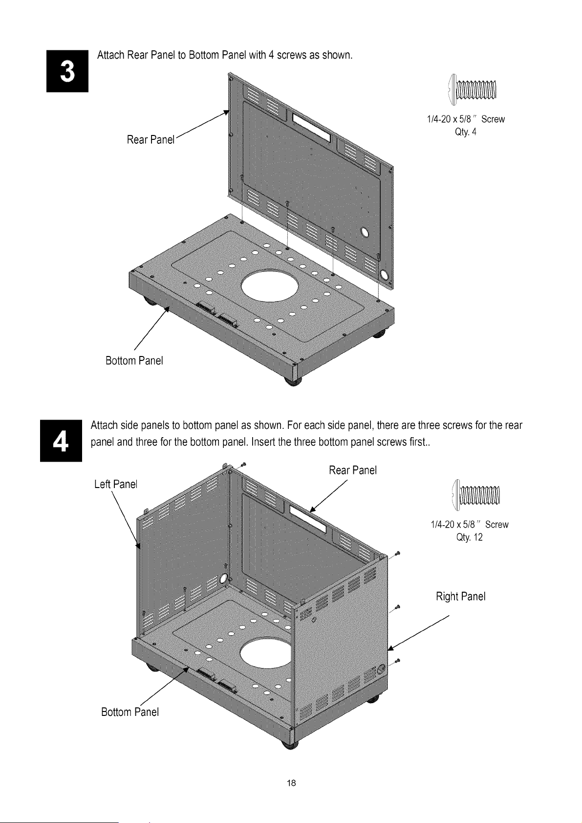
Attach Rear Panel to Bottom Panel with 4 screws as shown.
Rear Panel
1/4-20x 5/8" Screw
Qty.4
Bottom Panel
Attach side panels to bottom panel as shown. For each side panel, there are three screws for the rear
panel andthree for the bottom panel. Insert the three bottom panel screws first..
Le_ Panel
Rear Panel
1/4-20x 5/8" Screw
Qty.12
Right Panel
Bottom Panel
18
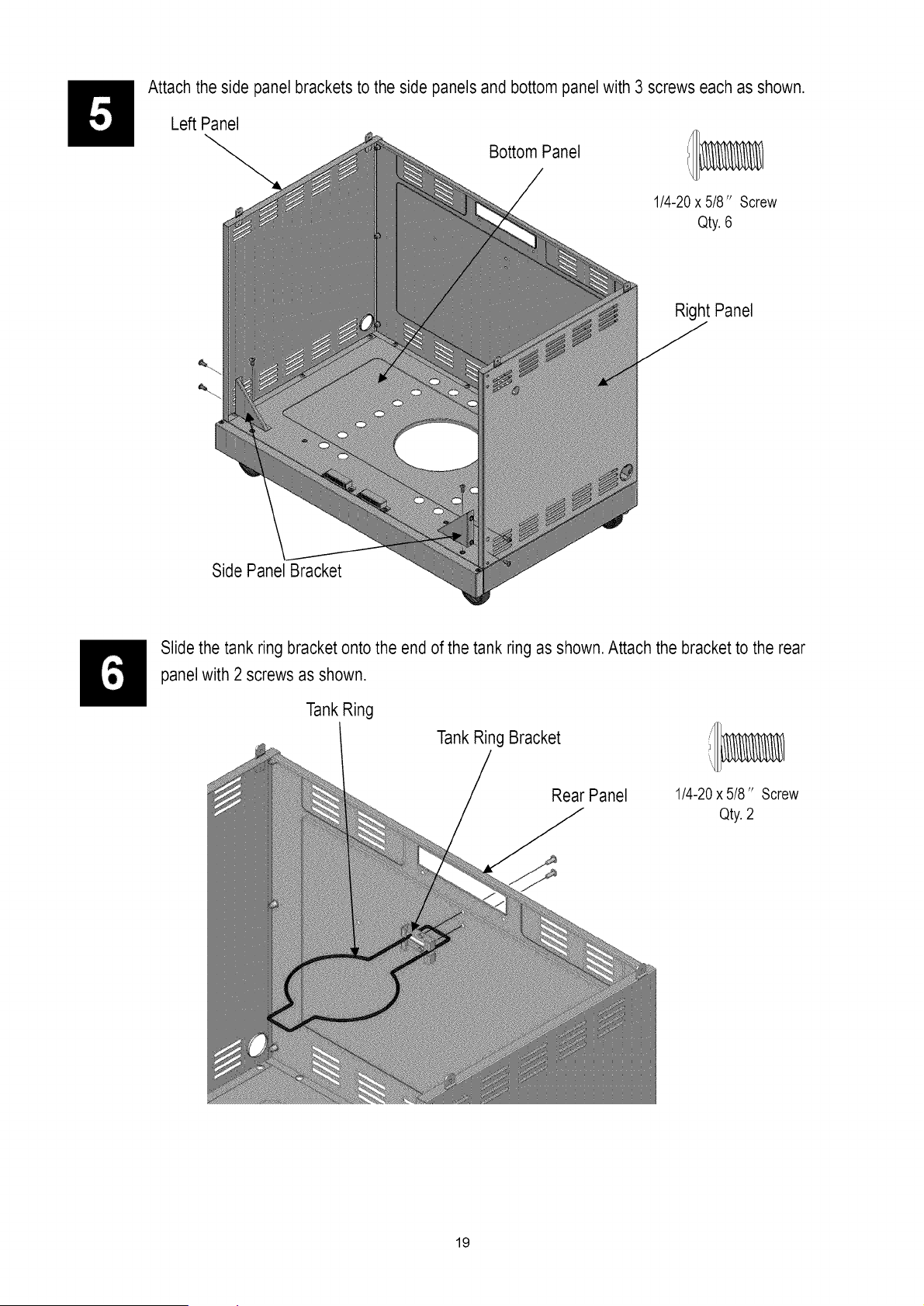
Attach the side panel brackets to the side panels and bottom panel with 3 screws each as shown.
Left Panel
Side Panel Bracket
Bottom Panel
1/4-20x 5/8" Screw
Qty. 6
Right Panel
Slide the tank ring bracket onto the end of the tank ring as shown. Attach the bracket to the rear
panel with 2 screws as shown.
Tank Ring
Tank Ring Bracket
Rear Panel
1/4-20x 5/8" Screw
Qty.2
19
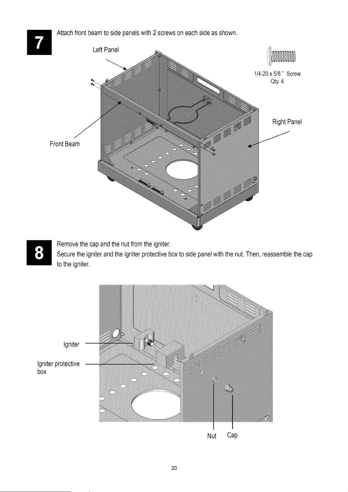
Attach front beam to side panels with 2 screws on each side as shown.
Left Panel
Front Beam
1/4-20x 5/8" Screw
Qty.4
Right Panel
Remove the cap and the nut from the igniter.
Secure the igniter and the igniter protective box to side panel with the nut. Then, reassemble the cap
to the igniter.
Igniter
Igniter protective
box
Nut Cap
20
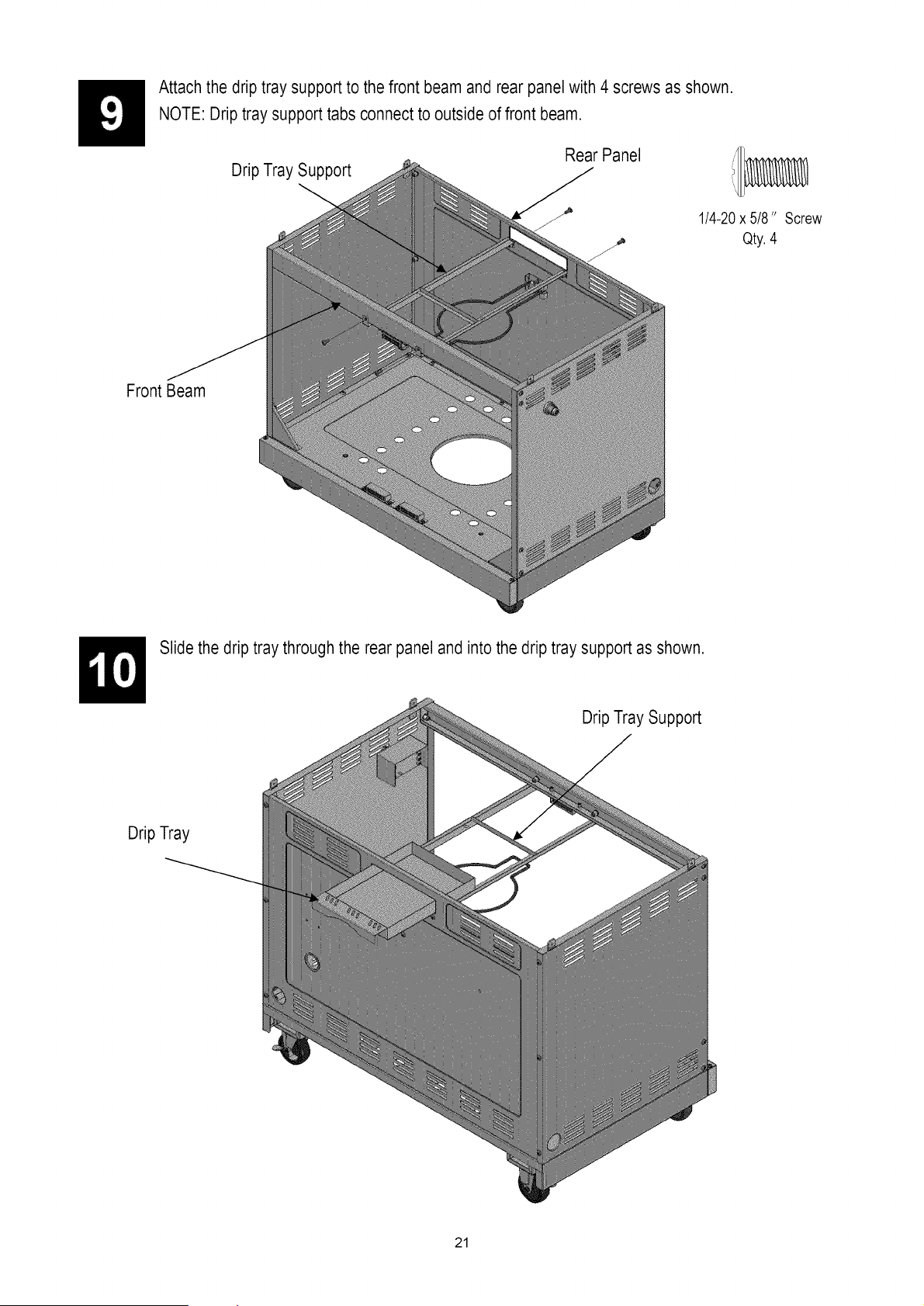
Attach the drip tray support to the front beam and rear panel with 4 screws as shown.
NOTE: Drip tray support tabs connect to outside of front beam.
Drip Tray Support
Rear Panel
1/4-20x 5/8" Screw
Qty.4
Front Beam
Slide the drip tray through the rear panel and into the drip tray support as shown.
Drip Tray Support
Drip Tray
21
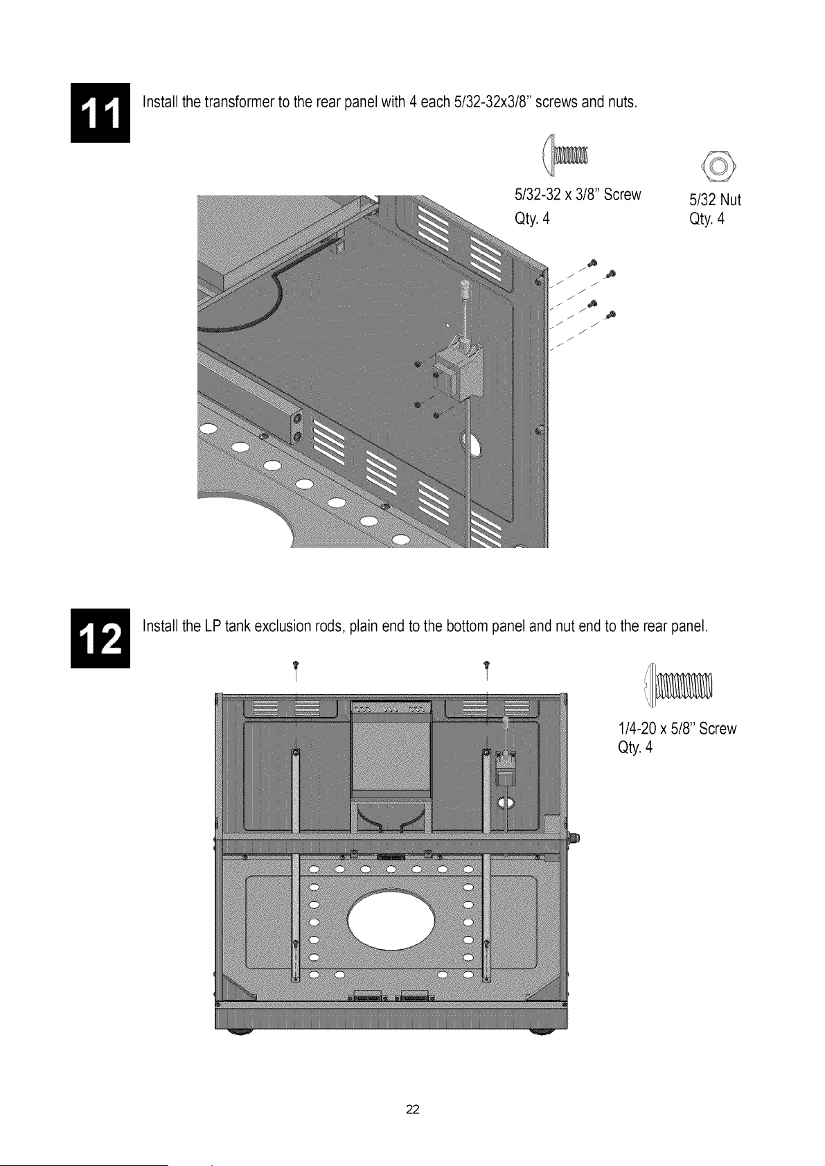
Install the transformer to the rear panel with 4 each 5/32-32x3/8" screws and nuts.
5/32-32 x 3/8" Screw
Qty. 4
5/32 Nut
Qty. 4
f
J
./,
./
_J
,,f ._
J. j
.s
J
Install the LP tank exclusion rods, plain end to the bottom panel and nut end to the rear panel.
1/4-20 x 5/8" Screw
Qty.4
22
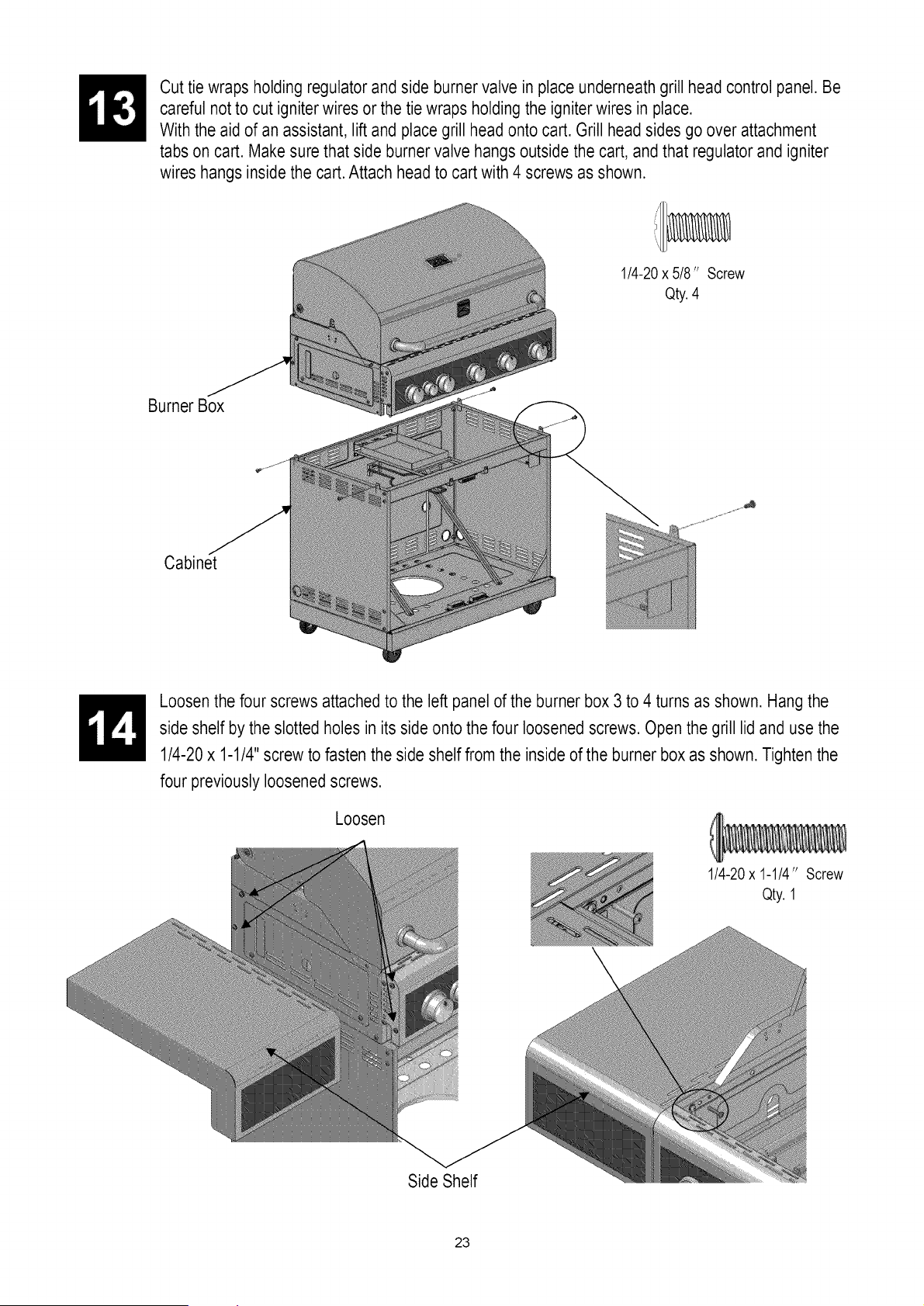
Cut tie wraps holding regulator and side burner valve in place underneath grill head control panel. Be
careful not to cut igniterwires or the tie wraps holding the igniter wires in place.
With the aid of an assistant, lift and place grill head onto cart. Grill head sides go over attachment
tabs on cart. Make sure that side burner valve hangs outside the cart, andthat regulator and igniter
wires hangs inside the cart.Attach head to cart with 4 screws as shown.
1/4-20x 5/8" Screw
Qty.4
Burner Box
Cabinet
Loosen the four screws attached to the left panel of the burner box 3 to 4 turns as shown. Hang the
side shelf by the slotted holes in its side onto the four loosened screws. Open the grill lid and use the
1/4-20 x 1-1/4"screw to fasten the side shelf from the inside of the burner box as shown. Tighten the
four previously loosened screws.
Loosen
1/4-20x 1-1/4" Screw
Qty. 1
Side Shelf
23

Side Burner Shelf
Loosen the four screws attached in the right panel of the burner box 3 to 4 turns as shown. Hang the
side burner shelf by the slotted holes in its side onto the four loosened screws. Open the grill lid and
use the 1/4-20x 1-1/4" screw to fasten the side burner shelf from the inside of the burner box as
shown. Tighten the four previously loosened screws.
Loosen
Side Burner Shelf
1/4-20x 1-1/4"Screw
Qty. 1
Side Burner Shelf
Loosen and remove the two screws holding side burner in place.Align the 2 bezel screw holes to
those in side burner control panel. Insertthe valve control stem through the hole in control panel and
bezel. Attach bezelto control panel andvalve control stem with 2 screws as shown. Press Knob onto
side burner valve control stem.
Side Burner Shelf
Bezel
M4x 8 Screw
Qty.2
/Knob
Side BurnerValve Control Stem
24
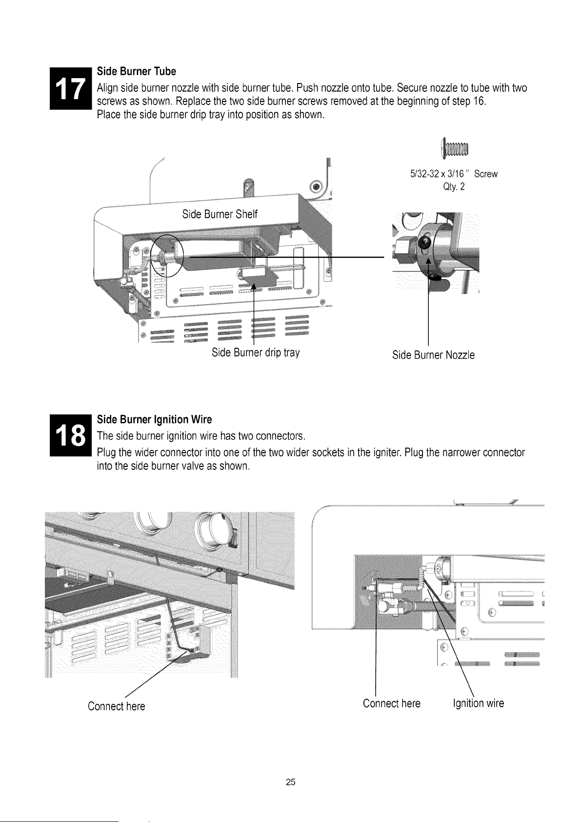
Side Burner Tube
Align side burner nozzlewith side burner tube. Push nozzle onto tube. Securenozzle to tube with two
screws as shown. Replace the two side burner screws removedat the beginning of step 16.
Place the side burner drip tray into position as shown.
Side Burner Shelf
Side Burnerdrip tray
5/32-32x 3/16" Screw
Qty.2
Side Burner Nozzle
Side Burner Ignition Wire
The side burner ignition wire has two connectors.
Plug the wider connector into one of the two wider sockets in the igniter.Plug the narrower connector
into the side burner valve as shown.
ii!iiJiiiil
i
Connect here
Connect here
Ignition wire
25
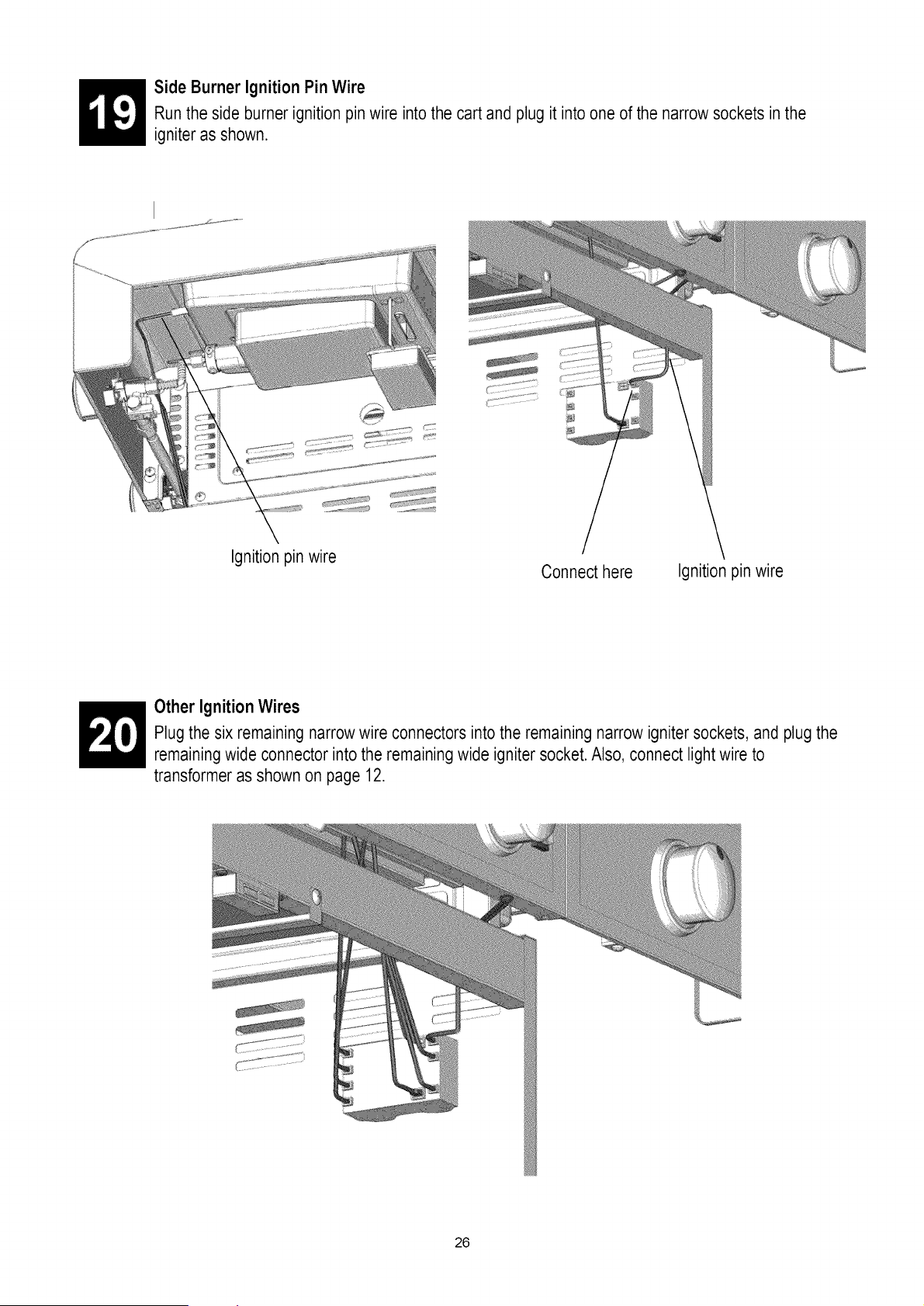
Side Burner Ignition Pin Wire
Run the side burner ignition pin wire into the cart and plug it into one of the narrow sockets in the
igniter as shown.
Ignition pin wire
Connect here
Ignition pin wire
Other Ignition Wires
Plug the six remaining narrow wire connectors into the remaining narrow igniter sockets, and plugthe
remainingwide connector into the remainingwide igniter socket. Also, connect light wire to
transformer as shown on page 12.
26
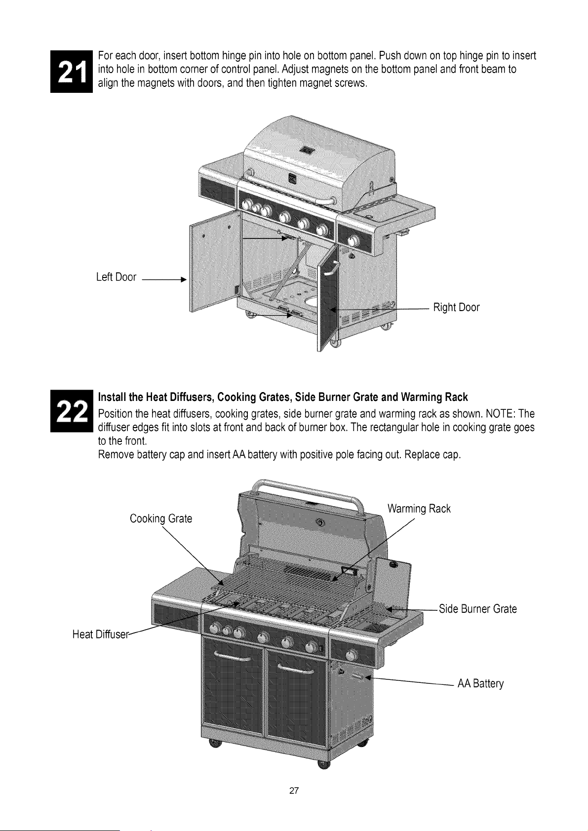
For each door, insert bottom hinge pin into hole on bottom panel. Pushdown on top hinge pin to insert
into hole in bottom corner of control panel. Adjust magnets on the bottom panel and front beam to
align the magnets with doors, and then tighten magnet screws.
Left Door ...
Right Door
Install the Heat Diffusers, Cooking Grates, Side Burner Grate and Warming Rack
Position the heat diffusers, cooking grates, side burner grate and warming rack as shown. NOTE: The
diffuser edges fit into slots at front and back of burner box. The rectangular hole in cooking grate goes
to the front.
Remove battery cap and insert AA battery with positive pole facing out. Replace cap.
Heat
Cooking Grate
Warming Rack
Burner Grate
AA Battery
27
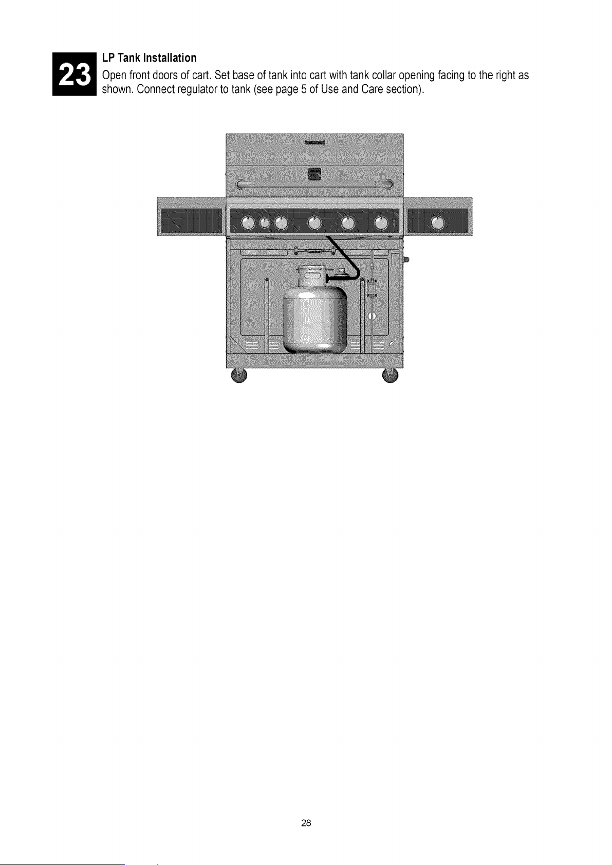
LP Tank Installation
Open front doors of cart. Set base of tank into cart with tank collar opening facing to the right as
shown. Connect regulator to tank (see page 5 of Use and Care section).
28
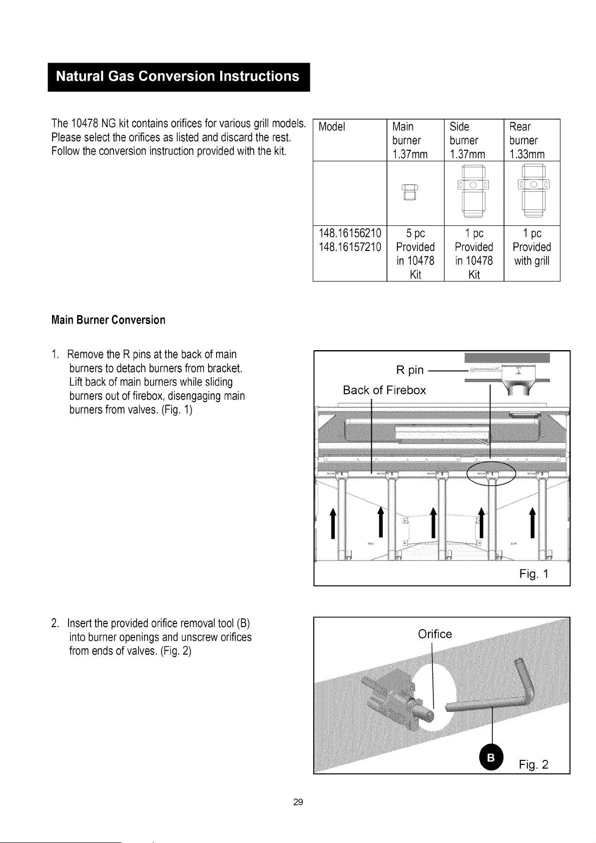
The 10478 NG kit contains orifices for various grill models.
Please select the orifices as listed and discard the rest.
Follow the conversion instruction providedwith the kit.
Model
148.16156210
148.16157210
Main Side
burner burner
1.37mm 1.37mm
5 pc 1 pc
Provided
in 10478
Kit
Provided
in 10478
Kit
Rear
burner
1.33mm
[ ]
1 pc
Provided
with grill
MainBurnerConversion
,
Remove the R pins at the back of main
burners to detach burnersfrom bracket.
Lift back of main burners while sliding
burners out of firebox, disengaging main
burners from valves. (Fig. 1)
R pin
Back of Firebox
I
Fig. 1
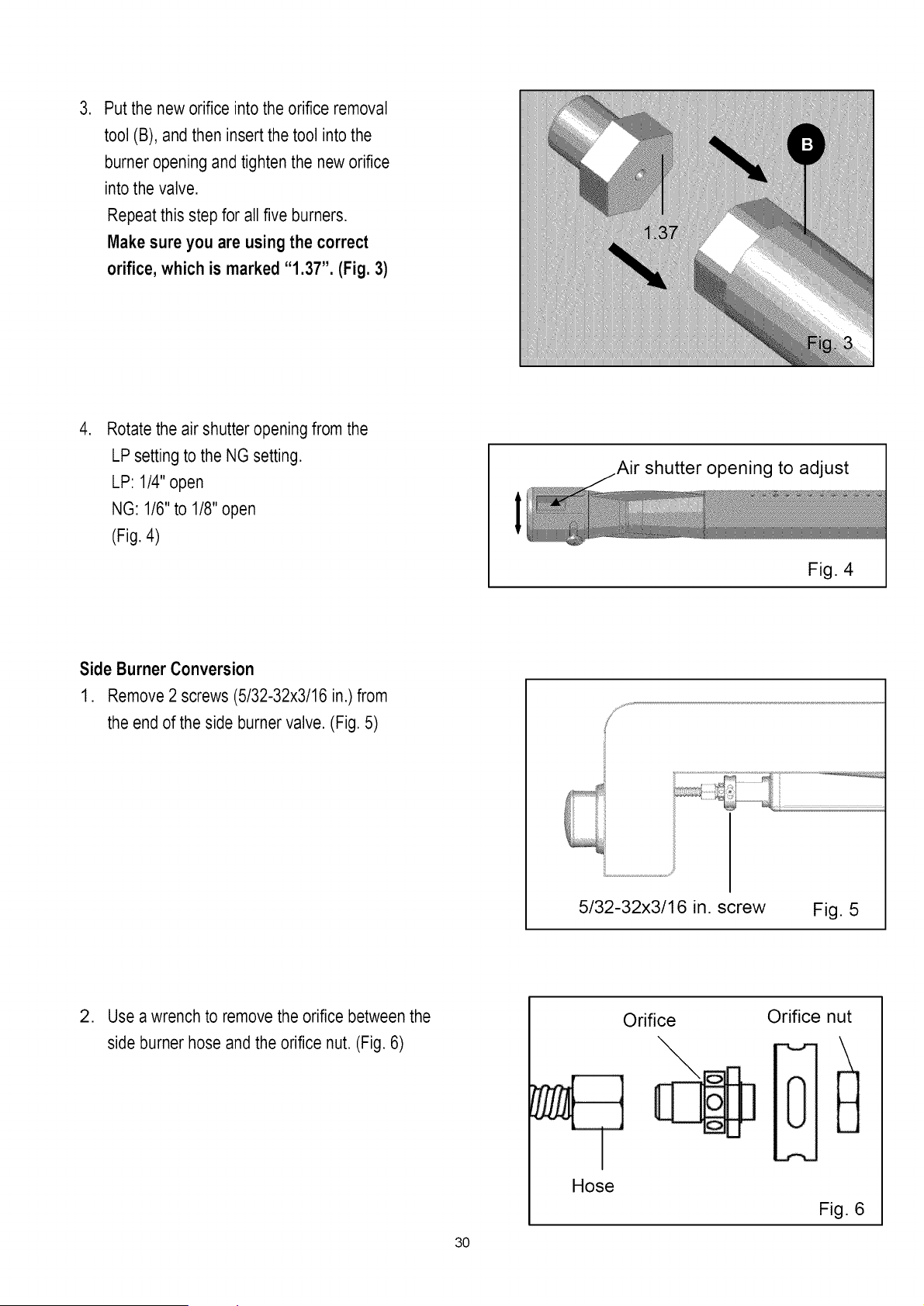
Orifice
,
Insert the provided orifice removal tool (B)
into burner openings and unscrew orifices
from ends of valves. (Fig. 2)
29
. Put the new orifice into the orifice removal
tool (B), and then insert the tool into the
burner opening and tighten the new orifice
into the valve.
Repeat this step for all five burners.
Make sure you are using the correct
orifice, which is marked "1.37". (Fig. 3)
.
Rotate the air shutter opening from the
LP setting to the NG setting.
LP: 1/4" open
NG: 1/6" to 1/8" open
(Fig. 4)
I
Air shutter opening to adjust
Fig. 4
I
Side Burner Conversion
1. Remove 2 screws (5/32-32x3/16 in.) from
the end of the side burner valve. (Fig. 5)
L
5/32-32x3/16 in. screw
Fig. 5
. Use a wrench to remove the orifice between the
side burner hose and the orifice nut. (Fig. 6)
30
Orifice
\
Orifice nut
Hose
Fig. 6

,
Tighten the new orifice to the valve.
Make sure you are using the correct
orifice, marked "1.37". (Fig. 7)
ili...................................................................................
1.37
Fig. 7
Rear Burner Conversion
,
Remove 5 screws (3/16-24 X 1/2 in.) at the back
of burner box to detach the rear burner cover
from the rear panel of burner box.
During this process, hold the rear burner
cover, otherwise, it will drop and may break,
possibly causing injury.(Fig. 8)
Rear burner
cover
Fig. 8
2. Use wrench to remove rear burner orifice
from the rear burner and the hose. (Fig. 9)
Orifice
Fig. 9
31
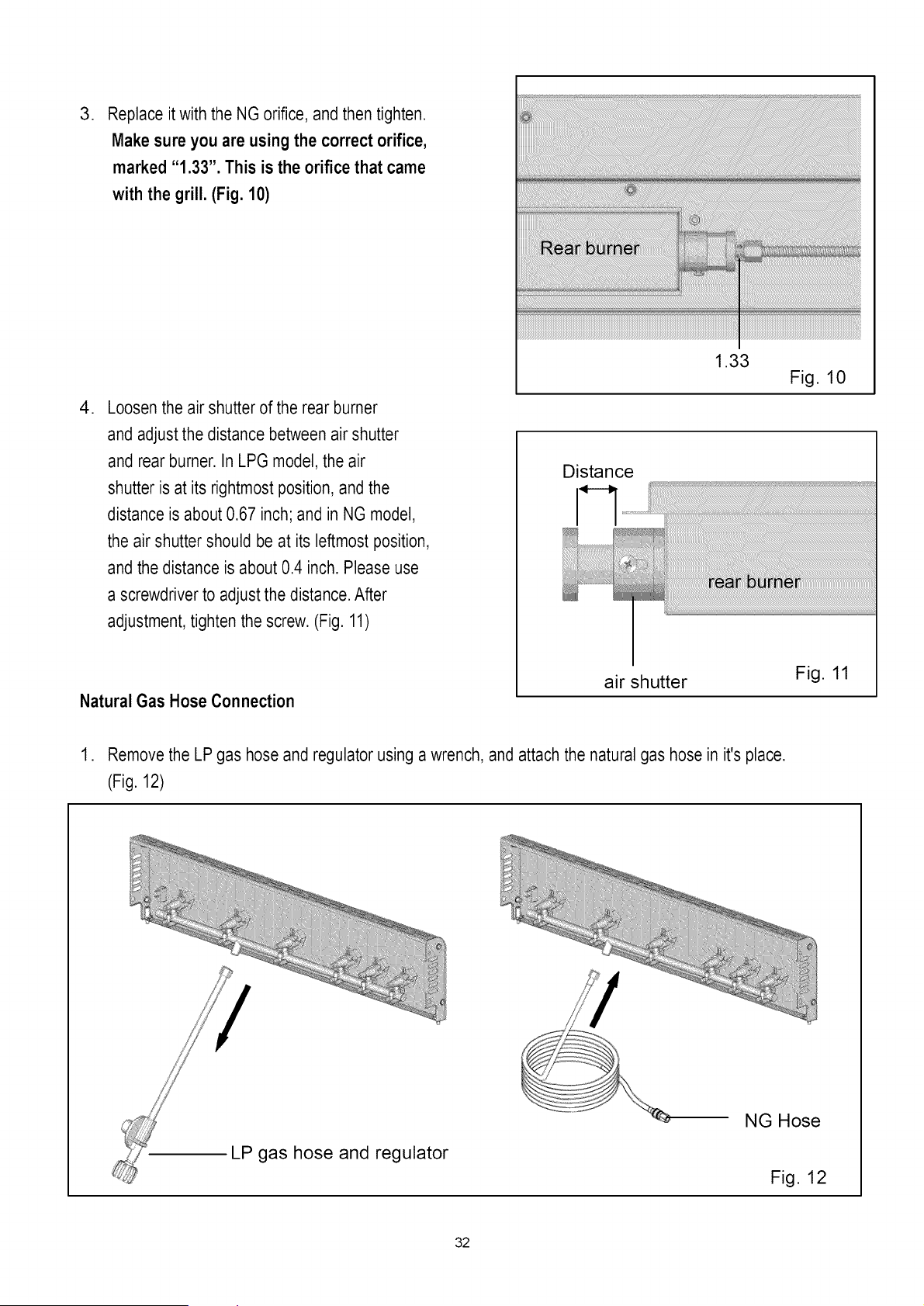
,
Replace it with the NG orifice, and then tighten.
Make sure you are using the correct orifice,
marked "1.33". This is the orifice that came
with the grill. (Fig. 10}
, Loosen the air shutter of the rear burner
and adjust the distance between air shutter
and rear burner. In LPG model, the air
shutter is at its rightmost position, and the
distance is about 0.67 inch; and in NG model,
the air shutter should be at its leftmost position,
and the distance is about 0.4 inch. Please use
a screwdriver to adjust the distance. After
adjustment, tighten the screw. (Fig. 11)
Natural Gas Hose Connection
1.33
Fig. 10
Distance
air shutter
Fig. 11
1. Remove the LP gas hose and regulator using a wrench, and attach the natural gas hose in it's place.
(Fig. 12)
LP gas hose and regulator
NG Hose
Fig. 12
32
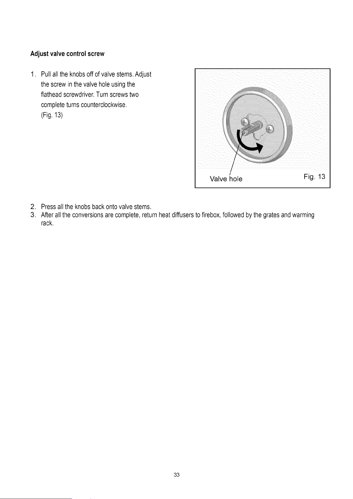
Adjust valve control screw
,
Pull all the knobs off of valve stems. Adjust
the screw in the valve hole using the
flathead screwdriver. Turn screws two
complete turns counterclockwise.
(Fig. 13)
I
/
!
Valve hole
Fig. 13
2. Press all the knobs back onto valve stems.
3. After all the conversions are complete, return heat diffusers to firebox, followed by the grates and warming
rack.
33
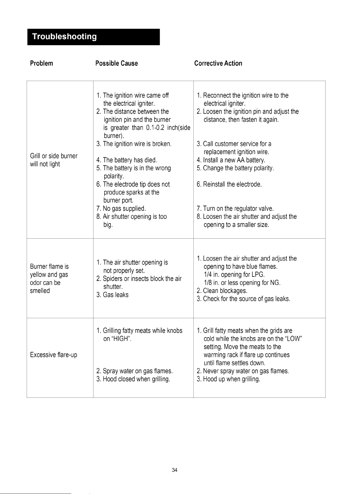
Problem Possible Cause Corrective Action
Grill or side burner
will not light
Burner flame is
yellow and gas
odor can be
smelled
Excessive flare-up
.
2.
.
4.
5.
6.
,
8.
The ignition wire came off
the electrical igniter.
The distance between the
ignition pin and the burner
is greater than 0.1-0.2 inch(side
burner).
The ignition wire is broken.
The battery has died.
The battery is in the wrong
polarity.
The electrode tip does not
produce sparks at the
burner port.
No gas supplied.
Air shutter opening is too
big.
1. The air shutter opening is
not properly set.
2. Spiders or insects block the air
shutter,
3. Gas leaks
1. Grilling fatty meats while knobs
on "HIGH".
2. Spray water on gas flames.
3. Hood closedwhen grilling.
1. Reconnectthe ignition wire to the
electrical igniter.
2. Loosen the ignition pin and adjust the
distance, then fasten it again.
3. Call customer service for a
replacement ignition wire.
4. Install a new AA battery.
5. Change the battery polarity.
6. Reinstall the electrode.
7. Turn on the regulator valve.
8. Loosenthe air shutter and adjust the
opening to a smaller size.
1. Loosenthe air shutter and adjust the
opening to have blue flames.
1/4 in. opening for LPG.
1/8 in. or less opening for NG.
2. Clean blockages.
3. Check for the source of gas leaks.
1. Grill fatty meats when the grids are
cold while the knobs are on the "LOW"
setting, Move the meats to the
warming rack if flare up continues
until flame settles down.
2. Never spray water on gas flames.
3. Hood up when grilling.
34
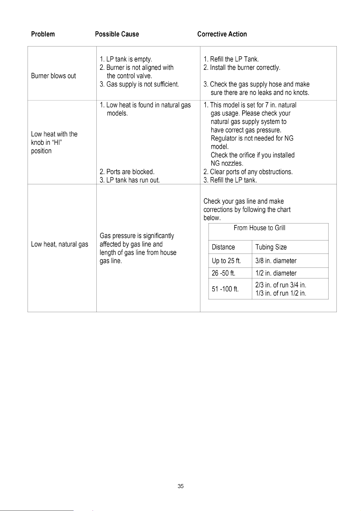
Problem Possible Cause Corrective Action
Burner blows out
Low heat with the
knob in "HI"
position
Low heat, natural gas
1. LP tank is empty.
2. Burner is not aligned with
the control valve.
3. Gas supply is notsufficient.
1. Low heat is found in natural gas
models.
2. Ports are blocked.
3. LP tank has run out.
Gas pressure is significantly
affected by gas line and
length of gas line from house
gas line.
1. Refill the LP Tank.
2. Install the burner correctly.
.
Check the gas supply hose and make
sure there are no leaks and no knots.
1. This model is set for 7 in. natural
gas usage. Please check your
natural gas supply system to
have correct gas pressure.
Regulator is not needed for NG
model.
Check the orifice if you installed
NG nozzles.
2. Clear ports of any obstructions.
3. Refill the LP tank.
Check your gas line and make
corrections by following the chart
below.
From House to Grill
Distance Tubing Size
Up to 25 ft. 3/8 in. diameter
26 -50 ft. 1/2 in. diameter
2/3 in. of run 3/4 in.
51 -100 ft.
1/3 in. of run 1/2 in.
35
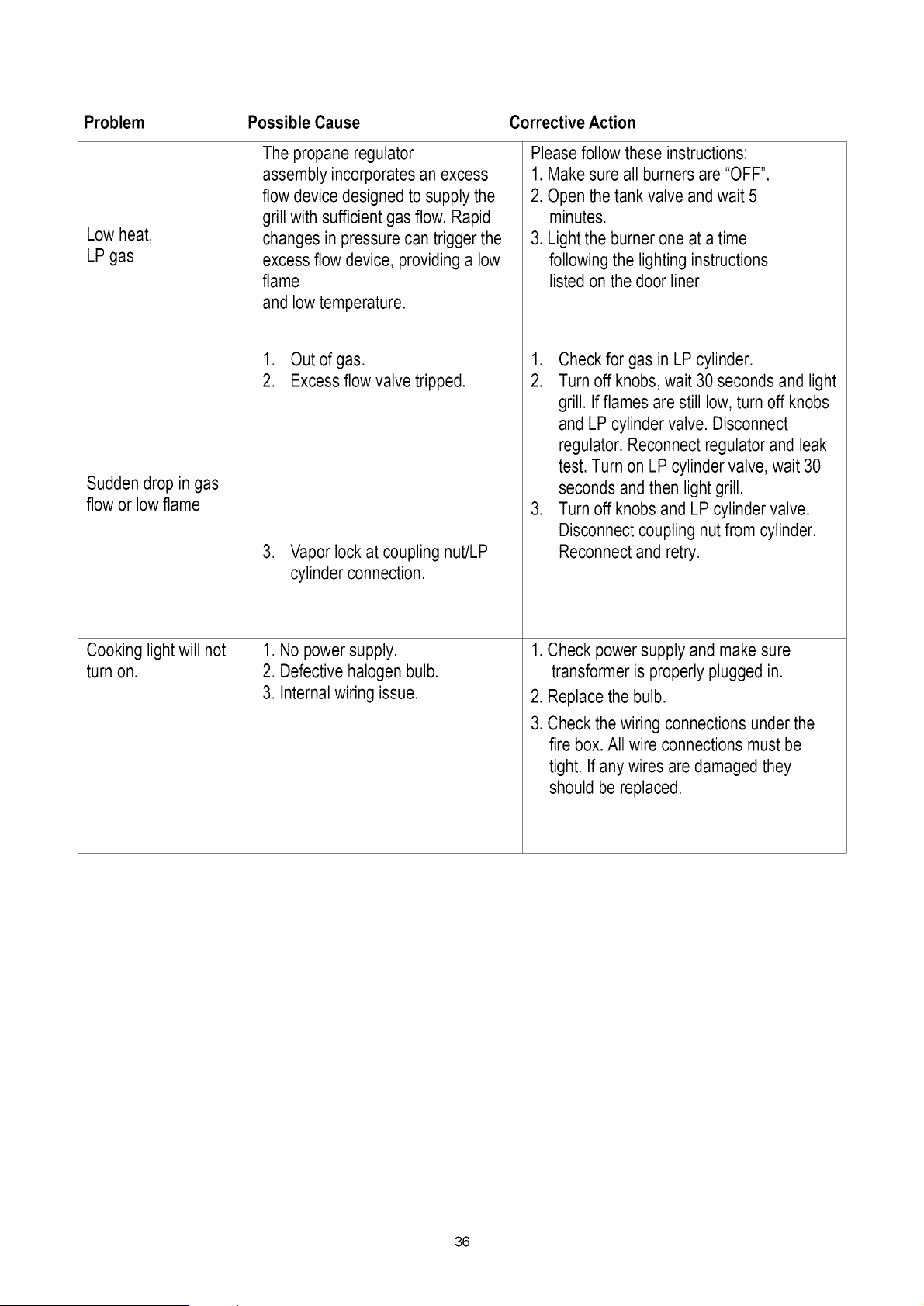
Problem Possible Cause Corrective Action
Low heat,
LP gas
Sudden drop in gas
flow or low flame
Cooking light will not
turn on.
The propane regulator
assembly incorporates an excess
flow device designed to supply the
grill with sufficient gas flow. Rapid
changes in pressurecan trigger the
excess flow device, providing a low
flame
and low temperature.
1. Out of gas.
2. Excess flow valve tripped.
3. Vapor lock at coupling nut/LP
cylinder connection.
1. No power supply.
2. Defective halogen bulb.
3. Internal wiring issue.
Please follow these instructions:
1. Make sure all burners are "OFF".
2. Open the tank valve and wait 5
minutes.
3. Lightthe burner one at a time
following the lighting instructions
listed on the door liner
1. Check for gas in LP cylinder.
2. Turn off knobs, wait 30 seconds and light
grill. If flames are still low, turn off knobs
and LP cylinder valve. Disconnect
regulator. Reconnect regulator and leak
test. Turn on LP cylinder valve, wait 30
seconds and then light grill.
3. Turn off knobs and LP cylinder valve.
Disconnect coupling nutfrom cylinder.
Reconnectand retry.
1. Check power supply and make sure
transformer is properly plugged in.
2. Replacethe bulb.
3. Check the wiring connections under the
fire box. All wire connections must be
tight. If any wires are damaged they
should be replaced.
36
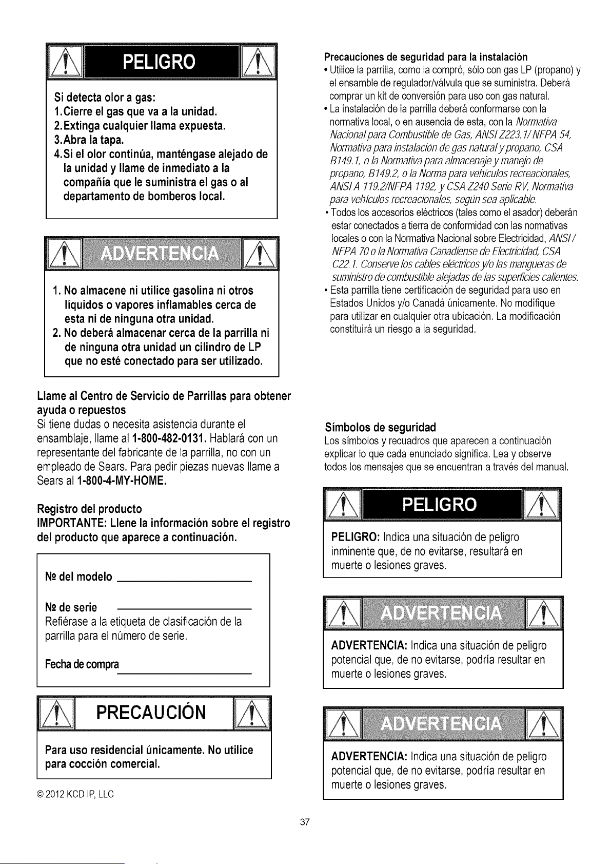
Si detecta olor a gas:
1.¢ierre el gas que va a la unidad.
2. Extinga cualquier llama expuesta.
3.Abra la tapa.
4.Si el olor contint)a,mantengase alejado de
la unidady Ilame de inmediato a la
compahia que le suministra el gas o al
departamentode bomberos local.
1. No almacene ni utilice gasolina ni otros
liquidos o vapores inflamables cerca de
esta ni de ninguna otra unidad.
2. No debera almacenar cerca de la parrilla ni
de ninguna otra unidad un cilindro de LP
que no este conectado para ser utilizado.
Precauciones de seguridad para la instalacion
• Utilice Ia parrilIa,como Ia compr6, s61ocon gas LP (propano) y
el ensambtede regulador/v_lvutaque se suministra. Deber_
comprarun kit de conversi6n para uso con gas natural.
• La instalaci6n de Ia parrilIadebera conformarse con ta
normativa local,o en ausencia de esta, con ta Normativa
Naciona/para Combustiblede Gas,ANSI Z223.7/NFPA 54,
Normativapara insta/acionde [7asnatural y propano, CSA
B 149.7,o/a Normativapara almacenajey manejo de
propano, B749.2,o/a Norma para vehfculosrecreacionales,
ANSI A 779.2/NFPA 7192,y CSA Z240 Serie RV, Normativa
para vehfculosrecreaciona/es,segfin sea aplicab/e.
• Todoslos accesorioselectricos(tales comoel asador)debergn
estarconectadosa tierra de conformidadcon las normativas
localeso con la Normativa Nacionalsobre Electricidad,ANSI/
NFPA 70 o/a Normativa Canadiensede E/ectricidad,CSA
C22.7. Conservelos cables electficosy/o /asmanguerasde
suministrode combustiblealejadasde/as superficiescalientes.
• Esta parrilla tiene certificaci6n de seguridad para uso en
Estados Unidos y/o Canada Qnicamente.No modifique
para utiIizar en cuatquier otra ubicaci6n. La modificaci6n
constituir9 un riesgo a la seguridad.
Llame al Centro de Servicio de Parrillas para obtener
ayuda o repuestos
Si tiene dudas o necesita asistencia durante el
ensamblaje, Ilame al 1-800-482-0131.Hablara con un
representante del fabricante de la parrilla, no con un
empleado de Sears. Para pedir piezas nuevas Ilame a
Sears al 1-800-4-MY-HOME.
Registro del producto
IMPORTANTE: Llene la informacion sobre el registro
del producto que aparece a continuacion.
N-odel modelo
N2de serie
Refierase a la etiqueta de clasificaci6nde la
parrilla para el nemerode serie.
Fechade compra
PRECAUCION
Para uso residencial t_nicamente.No utilice
para coccion comercial.
© 2012 KCDIP,LLC
Simbolos de seguridad
Lossimbotosy recuadrosqueaparecena continuaci6n
explicar Io que cadaenunciadosignifica. Lea y observe
todoslos mensajes quese encuentrana travesdel manual.
PELIGRO: Indica una situaci6n de peligro
inminente que, de no evitarse, resultara en
muerte o lesiones graves.
ADVERTENClA: Indica una situaci6n de peligro
potencial que, de no evitarse, podria resultar en
muerte o lesiones graves.
ADVERTENClA: Indica una situaci6n de peligro
potencial que, de no evitarse, podria resultar en
muerte o lesiones graves.
37
Para su seguridad ................................ 37
Centre de Servicio para ta parrilIa .................... 37
Informaci6n de registro del producto.................. 37
Simbotos de seguridad............................. 37
Precauciones de seguridad para la instataci6n........... 37
Garantia de Ia parrilIa Kenmore ........................ 38
Uso y cuidado ................................ 39-46
Instrucciones para la conexi6n del transformador ......... 47
Gas Natural Kit de conversi6n.......................... 49
Lista de piezas................................................................... 50
Diagrama de piezas ................................ 51
Ensambtaje......................................... 52-53
Instrucciones de conversi6n de gas natural ............ 54-58
Sotuci6n de probtemas........................... 59-71
Acuerdos de proteccion para reparacion
Felicitaciones por su compra inteligente. Su nuevo producto
Kenmore ®est_ disefiado y fabricado para brindarle a_os de
funcionamiento confiabte. Pero, como cuatquier otto producto,
puede que requiera reparaciones de cuando en cuando. Es atli
cuando tener un Acuerdo de protecci6n para reparaci6n puede
ahorrarle dinero y motestias.
Adquiera un Acuerdo deprotection de reparation ahora y
protejase de mo/estiasy gastos impre vistos.
He aqui io que el acuerdo de protecci6n para reparaci6nincluye:
[] Servicio experto por parte de nuestros 10.000
especiatistas profesionales de reparaciones.
[] Servicio ilimitado sin cargo para tas piezas y mano de
obra de todas ias reparaciones amparadas
[] Reemplazo del producto hasta $1500 si el producto
amparado no puede arreglarse
[] Descuento del 25% del precio regular del servicio y ias
piezas relacionadas instaladas no amparadas por el
acuerdo; tambien, 25% de descuento sobre el precio
regular de Ias revisiones preventivas de mantenimiento
[] Ayuda telefonica rapida-Ia tlamamos Resotuci6n
Rgpida - apoyo telef6nico de un representante Sears. Piense
en nosotros como un manual de servicio parlante.
Una vez que haya adquiridoel Acuerdo de Protecci6npara
repara-ci6n,una simpleIlamadatelef6nica es todo Io que
necesitapara programarel servicio. PuedeIlamaren cualquier
momento,de dia o de noche, o programaruna cita de servicioa
travesde Internet.
El Acuerdo de Protecci6n para reparaci6n es una compra sin
riesgos. Si cancela por cuatquier raz6n durante el periodo de
garantia del producto, Ie proporcionaremos un reembotso
compteto. O un reembotso prorrateado en cuatquier momento
despues de que venza et periodo de garantia del producto.
iAdquiera su Acuerdo de Protecci6n para Reparaci6n hoy
mismo!
Some limitations and exclusions apply.
For prices and additional information call 1-800-827-6655.
Sears Installation Service
Ciertas limitaciones y exclusionesaplican.
Para precios e informacionadicional,Ilame al 1-800-827-6655.
Serviciode instalacionSears
Para /a insta/acion profesiona/ de electrodomesticos Sears,
abridores de puertas de garaje, calentadores de aguay
cualquier otro artfculo grande en EE.UU., /lame al
1-600-4-MY-I-IOME®
Garantia total Kenmore
Siesta parriiia presenta una fatia originada por un defecto de
material o mano de obra, dentro de un aSo a partir de ia
fecha de compra, iiame al 1-800-4-MY- HOME® para
obtener reparaci6n gratis (o reemplazo si no fuese posibte
efectuar Ia reparaci6n).
Garantia limitada en los quemadores
Durante diez aSos a partir de Ia fecha de compra, cuatquier
quemador de acero inoxidabte que se oxide comptetamente
ser_ reemptazado sin costo. Despues del primer aSoa partir
de Ia fecha de compra, usted paga por Ia mano de obra si
desea que se Io instaten.
Toda ta cobertura de garantia excluye ias baterias del
encendedor y ia perdida de pintura de ias partes de ia
parrilIa, Ia decotoraci6n o el 6xido, los cuales son partes
fungibtes que pueden gastarse con el uso normal dentro del
periodo de garantia, o son situaciones que podrian
producirse por el uso normal, accidente o mantenimiento
inadecuado.
Toda la cobertura de garantia queda anutada si Ia parrilIa se
utiliza para fines comerciates o en atquiler.
Toda la cobertura de garantia aplica Onicamentesi ia parriiia
se utiiiza en Estados Unidos.
Esta garantia te otorga derechos iegates especificos yes
posibte que usted goce de otros derechos que varian segQn
el estado.
Sears, Roebuck and Co., Hoffman Estates, IL 60179
38
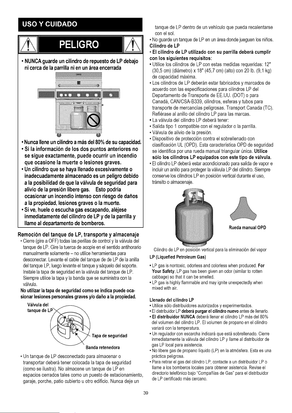
• NUNCAguardeuncilindroderepuestodeLPdebajo
nicercadela parrillanien unareaencerrada
• NuncaIleneun cilindroa masde180%de su capacidad.
• Si la informacion de los dos puntos anteriores no
se sigue exactamente, puede ocurrir un incendio
que ocasione la muerte o lesiones graves.
• Un cilindroque se haya Ilenadoexcesivamenteo
inadecuadamentealmacenadoes un peligrodebido
a la posibilidadde que la valvula de seguridad para
aliviode la presionliberegas. Esto podria
ocasionarun incendiointensoconriesgo de dahos
a la propiedad,lesionesgraveso la muerte.
• Si ve, hueleo escuchagas escapando,alejese
inmediatamentedel cilindrode LP y de la parrillay
Ilameal departamentode bomberos.
Remocion del tanque de LP, transporte y almacenaje
• Cierre(gire a OFF) todas IasperilIasde controly Ia valvuladel
tanquede LP. Gire Ia tuerca de acople en el sentido antihorario
manualmentesotamente- no utiliceherramientaspara
desconectar.Levanteel cable del tanquede de LPde Ia aniIIa
deltanque LP, hego Ievanteel tanquey saquelodel soporte.
InstaleIa tapa de seguridaden ta valvuladel tanquede LP.
SiempreutiliceIa tapa y Ia banda que se suministracon ta
valvula.
No utilizar la tapa de seguridadcomo se indica puede oca-
sionarlesiones personales graves y/o daSo a la propiedad.
Wlvula del
L_ Tapade seguridad
tanque
de
Bandaretenedora
• Un tanque de LP desconectado para atmacenar o
transportar debera tener cotocada ta tapa de seguridad
(como se ilustra). No atmacene un tanque de LP en
espacios cerrados tales como un puesto de estacionamiento,
garaje, porche, patio cubierto u otro edificio. Nunca deje un
tanque de LP dentro de un vehicuto que pueda recatentarse
con el sot.
• No guarde untanque de LP en un areadonde jueguen los ni_os.
Cilindro de LP
• El cilindro de LP utilizado con su parrilla debera cumplir
con los siguientes requisitos:
• Utilice los cilindros de LP con estas medidas requeridas: 12"
(30,5 cm) (diametro) x 18" (45,7 cm) (alto) con 20 lb. (9,1 kg)
de capacidad maxima.
• Los cilindros de LP deberan estar fabricados y marcados de
acuerdo con tas especificaciones para cilindros LP del
Departamento de Transporte de EE.UU. (DOT) o para
Canada, CAN/CSA-B339, cilindros, esferas y tubos para
transporte de mercancias petigrosas. Transport Canada (TC).
Refierase at anilIo del cilindro LP para tas marcas.
• La valvuta del cilindro LP debera tener:
• Salida tipo 1 compatible con el regutador o Ia parrilIa.
• Valvuta de ativio de Ia presi6n.
• Dispositivo de protecci6n contra el sobrellenado con
clasificaci6n UL (OPD). Esta caracteristica OPD de seguridad
se identifica por una rueda manual triangular Qnica.Utilice
solo los cilindros LP equipados con este tipo de valvula.
• El ciIindroLP debera estar acondicionadoparasalida de vapor e
incur un anilIo paraproteger Iavalvula LPdel cilindro. Siempre
conservelos cilindrosLPen posici6nverticalduranteel uso,
transitoo almacenaje.
RuedamanualOPD
Cilindrode LPen posici6nverticalparala eliminaci6ndel vapor
LP (LiquefiedPetroleumGas)
• LPgas is nontoxic,odorlessandcolorlesswhen produced.For
Your Safety, LP gas hasbeengivenan odor(similarto rotten
cabbage)so thatit can besmelled.
• LPgas is highlyflammableand mayigniteunexpectedlywhen
mixedwithair.
Llenadodel cilindroLP
• Utilices61odistribuidoresautorizadosy experimentados.
• EldistribuidorLPdeberapurgarel cilindronuevoantesde Ilenarlo.
• El distribuidor NUNOAdeber_Ilenarel cilindroLP m_sdel 80%
delvolumendel cilindroLP. Elvolumende propanoen el cilindro
variar_con latemperatura.
• Un reguladorcon escarchaindicar_queest_ sobrellenado.Cierre
inmediatamentelav&lvuladel cilindroLPy Ilameal distribuidorde
gas LPlocalparaasistencia.
• No liberegasde propanoliquido(LP)en la atm6sfera.Estaes una
pr&cticapeligrosa.
• Pararetirarel gasdelcilindroLP,contactea un distribuidorLPo
Ilamea los bomberoslocalesparaobtenerasistencia.Reviseel
directoriotelef6nicobajo "CompaSiasdeGas"paraeldistribuidor
deLPcertificadom_scercano.
39
Intercambio del tanque LP
• Muchosdistribuidoresque venden parrilIasofrecenla opci6nde
reemplazarsu tanque vacio de LP a travesde un servicio de
intercambio.Utilices61oIasempresasde intercambiocon repu-
taci6nque inspeccionan,Ilenancon precisi6n,pruebany
certificansus cilindros.Intercambie su tanque s61opot un
tanque equipado con la caracteristica de seguridad OPD
segun se describe en la secci6n "Tanque LP" de este
manual.
• Siempre conserve los tanques LP nuevos e intercambiados
en posici6n vertical durante el uso, transporte o atmacenaje.
• Haga la prueba de fugas en los tanques LP
intercambiados ANTES de conectarlo a la parrilla.
Prueba de fuga del tanque LP
Parasuseguridad
• La prueba de fuga debera repetirse cada vez que se
intercambia o se rellena un tanque de LP.
• No fume durante Ia prueba de fugas.
• No utilice una llama expuesta para revisar Ias fugas de gas.
• La parrilIa debera probarse en busca de fugas en exteriores,
en un area bien ventilada, atejada de las fuentes de ignici6n
tales como los aparatos de encendido a gas o electrico.
Durante Ia prueba de fugas, mantenga ta parrilIa atejada de
Iasllamas expuestas o chispas.
• Utilice una brocha limpia y una sotuci6n de 50/50 detergente
suave y agua. Aptique Ia sotuci6n jabonosa en las areas que
indican las flechas de Ia flgura. Las fugas se identifican
mediante burbujas crecientes.
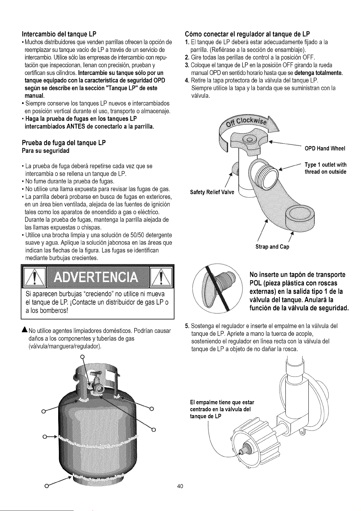
Como conectar el regulador al tanque de LP
1. El tanque de LP debera estar adecuadamente fijado a ta
parrilIa. (Refierase a ta secci6n de ensambtaje).
2. Gire todas Ias perilIas de control a la posici6n OFF.
3. Cotoqueel tanque de LP en la posici6n OFFgirando Ia rueda
manualOPD en sentidohoratiohastaquese detenga totalmente.
4. Retire Ia tapa protectora de Ia valvula del tanque LP.
Siempre utilice Ia tapa y Ia banda que se suministran con ta
valvula.
_---- OPDHandWheel
S _ _ Type 1°utlet with
threadon outside
SafetyRelie
Strap andCap
Si aparecen burbujas "creciendo" no utilice ni mueva
el tanque de LP. iContacte un distribuidor de gas LP o
a los bomberos!
No inserte un tapon de transporte
POL (pieza plastica con roscas
externas) en la salida tipo 1 de la
valvula del tanque. Anulara la
funcion de la valvula de seguridad.
• No utiIice agentes Iimpiadores domesticos. Podrian causar
dafios a los componentes y tuberias de gas
(valvuta/manguera/regulador).
5. Sostenga el regutador e inserte el empatme en ta valvuta del
tanque de LP. Apriete a mano Ia tuerca de acopte,
sosteniendo el regutador en tinea recta con ta valvuta del
tanque de LP a objeto de no dafiar Ia rosca.
El empalmetiene queestar
centradoen la valvuladel
tanquede LP
40
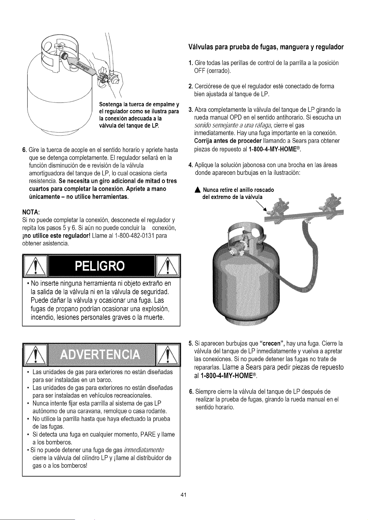
Sostengalatuercade empalmey
el reguladorcomose ilustrapara
laconexionadecuadaa la
valvuladel tanquede LP.
6. Gire Ia tuerca de acople en el sentido horario y apriete hasta
que se detenga completamente. El regutador sellar_ en ta
funci6n disminuci6n de e revisi6n de Ia v_lvuta
amortiguadora del tanque de LP, Io cuat ocasiona cierta
resistencia. Se necesita un giro adicional de mitad o tres
cuartos para completar la conexi6n. Apriete a mano
unicamente - no utilice herramientas.
NOTA:
Si no puede completar Ia conexi6n, desconecte el regutador y
repita los pasos 5 y 6. Si a_n no puede concluir Ia conexi6n,
ino utilice este reguladort Llame at 1-800-482-0131 para
obtener asistencia.
Valvulas para prueba de fugas, manguera y regulador
1. Gire todas Ias periIIas de control de Ia parriIIa a la posici6n
OFF (cerrado).
2. Cerci6rese de que el regulador este conectado de forma
bien ajustada at tanque de LP.
3. Abra comptetamente Ia v_lvuta del tanque de LP girando Ia
rueda manual OPD en el sentido antihorario. Si escucha un
sonido sernejante a una rafaga, cierre el gas
inmediatamente. Hay una fuga importante en ta conexi6n.
Corrija antes de proceder Ilamandoa Sears para obtener
piezas de repuesto al 1-800-4-MY-HOME®.
4. Aplique Ia sotuci6n jabonosa con una brocha en tas areas
donde aparecen burbujas en ta iIustraci6n:
• Nuncaretireel anilloroscado
delextremode la valv_a _
"a
• No inserte ninguna herramienta ni objeto extraSo en
la salida de la valvula ni en la valvula de seguridad.
Puede daSar la valvula y ocasionar una fuga. Las
fugas de propano podrian ocasionar una explosi6n,
incendio, lesiones personales graves o la muerte.
• Las unidades de gas para exteriores no est_n dise_adas
para ser instatadas en un barco.
• Las unidades de gas para exteriores no est_n dise_adas
para ser instatadas en vehicutos recreacionates.
• Nunca intente fijar esta parriIIa at sistema de gas LP
aut6nomo de una caravana, remotqueo casa rodante.
• No utiIice Ia parriIIahasta que haya efectuado Ia prueba
de Ias fugas.
• Si detecta una fuga en cualquier momento, PARE y IIame
a los bomberos.
• Si no puede detener una fuga de gas inmediatamente
cierre Ia v_lvuta del ciIindro LP y ilIame at distribuidor de
gas o a los bomberos!
5. Si aparecen burbujas que "crecen", hay una fuga. Cierre Ia
v_lvuta del tanque de LP inmediatamente y vuelva a apretar
Ias conexiones. Si no puede detener Ias fugas no trate de
repararlas. Llame a Sears para pedir piezas de repuesto
al 1-800-4-MY-HOME ®.
6. Siempre cierre Ia v_lvuta del tanque de LP despues de
reatizar Ia prueba de fugas, girando Ia rueda manual en el
sentido horario.
41
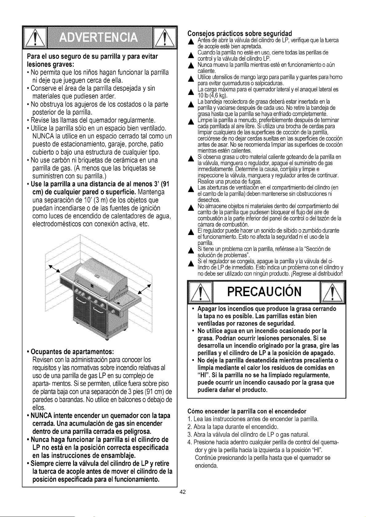
Para el uso seguro de su parrilla y para evitar
lesiones graves:
• No permita que los ni_os haganfuncionar la parrilla
ni deje que jueguen cerca de ella.
• Conserve el area de la parrilla despejada y sin
materiales que pudiesen arder.
• No obstruya los agujeros de los costadoso la parte
posteriorde la parrilla.
• Revise las llamas del quemador regularmente.
• Utilice la parrilla s61oen un espacio bien ventilado.
NUNCA la utilice en un espacio cerradotal como un
puesto de estacionamiento,garaje, porche, patio
cubierto o bajo una estructura de cualquier tipo.
• No use carb6n ni briquetas de ceramica en una
parrilla de gas. (A menosque las briquetas se
suministren con su parrilla.)
• Use la parrilla a una distancia de al menos 3' (91
cm) de cualquier pared o superficie. Mantenga
una separaci6nde 10' (3 m) de los objetos que
puedan incendiarse o de las fuentes de ignici6n
como luces de encendido de calentadores de agua,
electrodomesticoscon conexi6n activa, etc.
• Ocupantes de apartamentos:
Revisenconlaadministraci6nparaconocerlos
requisitosy lasnormativassobreincendiorelativasal
usode una parrillade gas LPen su complejode
aparta-mentos.Sise permiten,utilicefuera sobrepiso
de plantabajaconuna separaci6nde 3 pies(91 cm) de
paredeso barandas.No utiliceenbalconeso debajode
ellos.
• NUNCA intente encender un quemador con la tapa
cerrada. Una acumulaci6n de gas sin encender
dentro de una parrilla cerrada es peligrosa.
• Nunca haga funcionar la parrilla si el cilindro de
LP no esta en la posici6n correcta especificada
en las instrucciones de ensamblaje.
• Siempre cierre la valvula del cilindro de LP y retire
latuerca de acople antes de mover el cilindro de la
posici6n especificada para el funcionamiento.
42
Consejos practicos sobre seguridad
• Antesdeabrirlavalvuladelcilindrode LP,verifiqueque la tuerca
D de acopleest6bienapretada.
Cuandola parrillanoest6en uso,cierretodas lasperillasde
• controly lavalvuladel cilindroLP.
• Nuncamuevala parrillamientrasest6enfuncionamientoo a0n
caliente.
• Utiliceutensiliosde mangolargoparaparrillay guantesparahomo
paraevitarquemadurasosalpicaduras.
• Lacargamaximaparael quemadorlateraly elanaquellaterales
10Ib (4,6kg).
Labandejarecolectorade grasadeberaestarinsertadaenla
• parrillay vaciarsedespu6sdecadauso.No retirelabandejade
grasahastaque laparrillase hayaenfriadocompletamente.
• Limpielaparrillaa menudo,preferiblementedespu6sde terminar
cadaparrilladaalairelibre.Siutilizaunabrochadecerdaspara
limpiarcualquierade lassuperficiesdecocci6nde laparrilla,
cerci6resede nodejarcerdassueltasen lassuperficiesdecocci6n
antesdeasar.Nose recomiendalimpiarlassuperficiesde cocci6n
mientrasest6ncalientes.
• Siobservagrasau otromaterialcalientegoteandodelaparrillaen
lavalvula,manguerao regulador,apagueel suministrode gas
inmediatamente.Determinelacausa,corrijalay limpiee
inspeccionela valvula,mangueray reguladorantesde continuar.
Realiceunapruebadefugas.
• Lasaberturasdeventilaci6nenelcompartimientodelcilindro(en
elcarritode laparrilla)debenmantenersesinobstruccionesni
desechos.
• Noalmaceneobjetosnimaterialesdentrodelcompartimientodel
carritodela parrillaquepudiesenbloquearel flujodelairede
combusti6na laparteinferiordelpaneldecontrolodel taz6nde la
camaradecombusti6n.
• Elreguladorpuedehacerunsonidodesilbidoo zumbidodurante
elfuncionamiento.Estonoafectalaseguridadni el usode la
parrilla.
• Sitieneunproblemacon laparrilla,refi6rasea la"Secci6nde
sohci6nde problemas".
• Siel reguladorse congela,apaguela parrillay lavalvuladelci-
lindrode LP deinmediato.Estoindicaunproblemaconelcilindroy
nodebeser utilizadocon ning0nproducto,iRegreseal distribuidor!
• Apagar los incendios que produce la grasa cerrando
la tapa no es posible. Las parrillas estan bien
ventiladas por razones de seguridad.
• No utilice agua en un incendio ocasionado por la
grasa. Podrian ocurrir lesiones personales. Si se
desarrolla un incendio originado por la grasa, gire las
perillas y el cilindro de LP a la posicion de apagado.
• No deje la parrilla desatendida mientras precalienta o
limpia mediante el calor los residuos de comidas en
"HI". Si la parrilla no se ha limpiado regularmente,
puede ocurrir un incendio causado por la grasa que
pudiera daSar el producto.
Como encender la parrilla con el encendedor
1. Lea tas instrucciones antes de encender Ia parriIIa.
2. Abra ta tapa durante el encendido.
3. Abra ta v_lvuta del cilindro de LP o gas natural.
4. Presionehacia adentro cualquierperilIade controldel quema-
dory gire Ia perilIahacia la izquierdaa la posici6n"HI".
ContinQepresionandoIa perilIahasta queel quemador se
encienda.
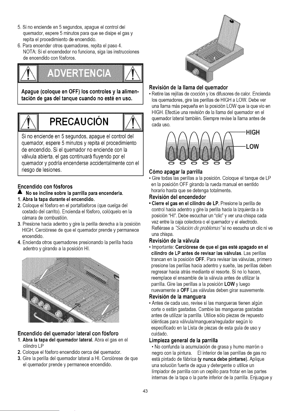
5.Sinoenciendeen5segundos,apagueelcontroldel
quemador,espere5minutosparaquesedisipeelgasy
repitaelprocedimientodeencendido.
6.Paraencenderotrosquemadores,repitaelpaso4.
NOTA:Sielencendedornofunciona,sigatasinstrucciones
deencendidoconf6sforos.
Apague (coloque en OFF) los controles y la alimen-
tacion de gas del tanque cuando no este en uso.
PRECAUClON
Si no enciende en 5 segundos, apague el control del
quemador, espere 5 minutos y repita el procedimiento
de encendido. Si el quemador no enciende con la
valvula abierta, el gas continuara fluyendo por el
quemador y podria encenderse accidentalmente con el
riesgo de lesiones.
Encendido con fosforos
• No se incline sobre la parrilla para encenderla.
1. Abra la tapa durante el encendido.
2. Coloque et f6sforo en et portaf6sforos (que cuetgadet
costado det carrito). Encienda el f6sforo, cot6quelo en ta
c_mara de combusti6n.
3. Presione hacia adentro y gire Ia periIla derecha a ta posici6n
HIGH. Cerci6rese de que el quemador prende y permanece
encendido.
4. Encienda otros quemadores presionando Ia periIIa hacia
adentro y girando a ta posici6n HI.
Encendido del quemador lateral con fosforo
1. Abra la tapa del quemador lateral. Abra el gas en el
ciIindro LP
2. Cotoque el f6sforo encendido cerca det quemador.
3. Gire Ia perilla del quemador lateral a HI. Cerci6rese de que
el quemador prende y permanece encendido.
Revision de la llama del quemador
• RetireIas rejiIIasde cocci6n y los difusores de calor. Encienda
los quemadores, gire Ias perilIasde HIGH a LOW. Debe ver
una llama m_s pequefia en ta posici6n LOW que Ia que vio en
HIGH. EfectQeuna revisi6nde Ia llama del quemador en el
quemador lateral tambien. Siempre revise Ia llama antes de
cada uso.
3H
Como apagar la parrilla
• Gire todas Ias perilIas a la posici6n. Cotoque el tanque de LP
en ta posici6n OFF girando Ia rueda manual en sentido
horario hasta que se detenga totatmente.
Revision del encendedor
• Cierre el gas en el cilindro de LP. Presione Ia periIIade
control hacia adentro y gire Ia perilIa hacia ta izquierda a ta
posici6n "HI". Debe escuchar un "clic" y ver una chispacada
vez entre Ia caja cotectorao el quemador y el electrodo.
Refierase a "5olucidn deproblemas"si no escucha un clic nive
una chispa.
Revision de la valvula
• Importante:Cerciorese de que el gas este apagado en el
cilindro de LP antes de revisar las valvulas. Las periIIas
trancan en la posici6n OFF. Para revisar Ias v_lvutas, primero
presione Ias periIIas hacia adentro y suelte, Ias periIIas deben
regresar hacia atr_s mediante el resorte. Si no Io hacen,
reemptace el ensambte de Ia v_lvuta antes de utiIizar Ia
parrilIa. Gire Ias perilIas a ta posici6n LOW y Iuego
nuevamente a OFF Las v_lvutas deben girar suavemente.
Revision de la manguera
• Antes de cada uso, revise si Ias mangueras tienen algQn
corte o est_n gastadas. Cambie Ias mangueras gastadas
antes de utiIizar Ia parriIIa. UtiIices6to piezas de repuesto
identicas para v_lvuta/manguera/regulador segQn1o
especificado en ta Lista de piezas de esta guia de uso y
cuidado.
Limpieza general de la parrilla
• No confunda ta acumulaci6n de grasa y humo marr6n o
negro con la pintura. El interior de Ias parriIIas de gas no
est_ pintado de f_brica (y nunca debe pintarse). Aptique
una sotuci6n fuerte de agua y detergente o utiIice un
Iimpiador de parriIIacon un cepiIIo para frotar en tas partes
internas de Ia tapa o Ia parte inferior de Ia parriIIa. Enjuague y
43
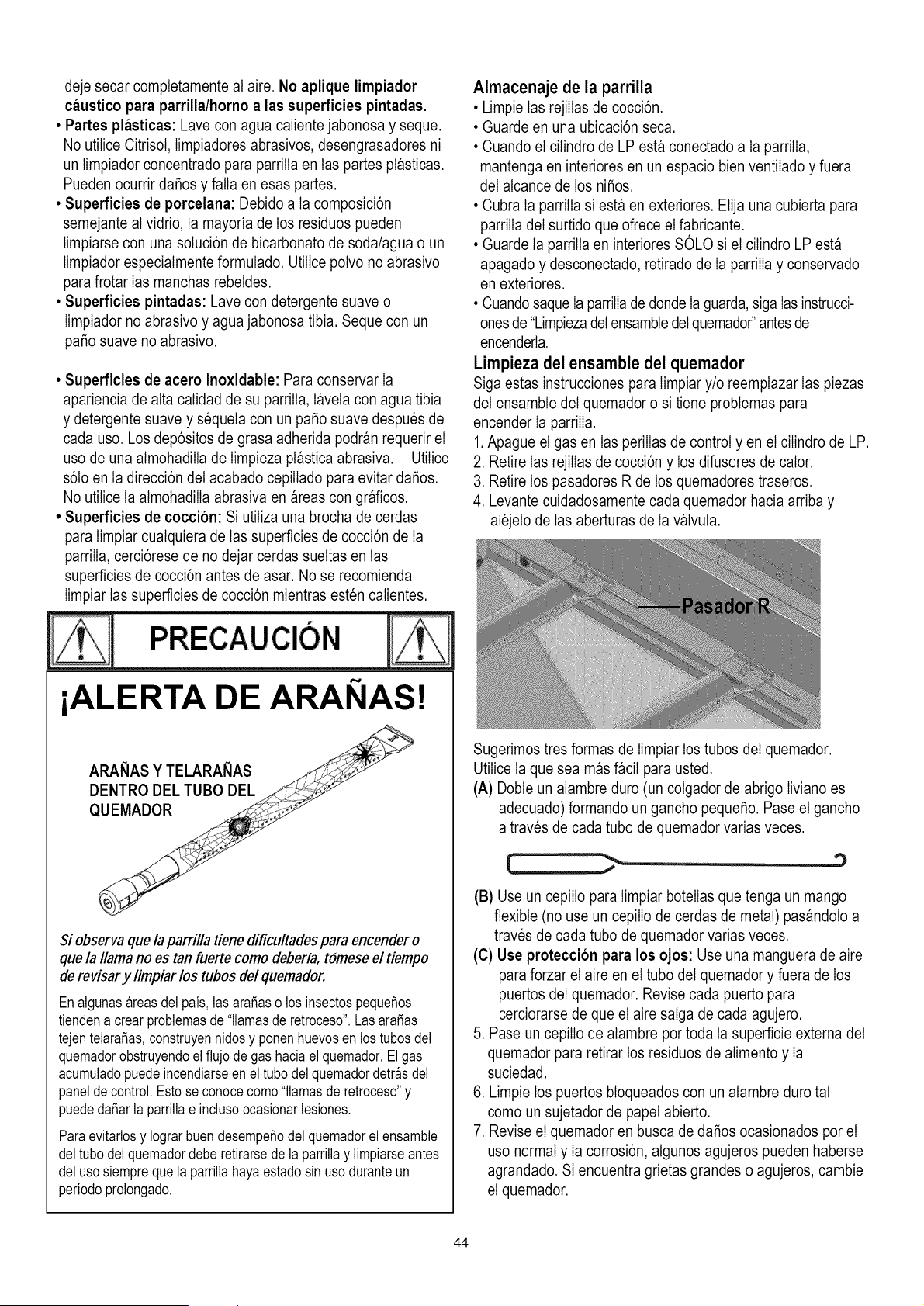
deje secar comptetamente at aire. No aplique limpiador
caustico para parrilla/horno a las superficies pintadas.
• Partes plasticas: Lave con agua calientejabonosa y seque.
No utiIice Citrisot, Iimpiadores abrasivos, desengrasadores ni
un timpiador concentrado para parrilIa en tas partes pDsticas.
Pueden ocurrir daSos y fatIa en esas partes.
• Superficies de porcelana: Debido a ta composici6n
semejante al vidrio, Ia mayoria de los residuos pueden
Iimpiarse con una sotuci6n de bicarbonate de soda/agua o un
Iimpiadorespeciatmente formulado. UtiIice potvo no abrasive
parafrotar Ias manchas rebeldes.
• Superficies pintadas: Lave con detergente suave o
Iimpiador no abrasivo y agua jabonosa tibia. Seque con un
paso suave no abrasive.
• Superficies de acero inoxidable: Para conservar Ia
apariencia de atta calidad de su parrilIa, Dvela con agua tibia
y detergente suave y sequela con un paso suave despues de
cada uso. Los dep6sitos de grasa adherida podr_n requerir el
uso de una atmohadilla de Iimpieza pDstica abrasiva. Utilice
s6to en ta direcci6n del acabado cepilIado para evitar daSos.
No utilice Ia atmohadilIa abrasiva en areas con graficos.
• Superficies de coccion: Si utiIiza una brocha de cerdas
para timpiar cuatquiera de Ias superficies de cocci6n de Ia
parrilIa,cerci6rese de no dejar cerdas sueltas en tas
superficies de cocci6n antes de asar. No se recomienda
Iimpiar Iassuperficies de cocci6n mientras esten catientes.
PRECAUCION
iALERTA DE ARANAS!
Si observa que la parrilla fiene dificultades para encender o
que la llama no es tan fuerte como deberia, tomeseel fiempo
derevisar y limpiar los tubos del quemador.
Enalgunas_reasdel pais, las araSaso los insectospequeSos
tiendena crear problemasde "llamasde retroceso".LasaraSas
tejentelaraSas,construyennidosy ponenhuevosen lostubosdel
quemadorobstruyendoelflujo degas haciaelquemador.El gas
acumuladopuedeincendiarseen el tubodel quemadordetr_sdel
paneldecontrol.Estose conocecomo"llamasde retroceso"y
puededaSarla parrillae inclusoocasionarlesiones.
Paraevitarlosy IograrbuendesempeSodelquemadorel ensamble
del tubodelquemadordeberetirarsede laparrillay limpiarseantes
del usosiemprequela parrillahayaestadosin usoduranteun
periodoprolongado.
Almacenaje de la parrilla
•Limpie las rejiIIasde cocci6n.
• Guarde en una ubicaci6n seca.
• Cuando el ciIindro de LP est_ conectado a la parriIIa,
mantenga en interiores en un espacio bien ventiIado y fuera
del atcance de los niSos.
• Cubra ta parrilIa siesta en exteriores. Elija una cubierta para
parriIIa del surtido que ofrece el fabricante.
• Guarde la parrilIa en interiores SOLO si el cilindro LP esta
apagado y desconectado, retirado de Ia parriIIa y conservado
en exteriores.
• Cuandosaque Ia parriIIade dondeIa guarda,siga tasinstrucci-
ones de"Limpiezadelensambledelquemador"antesde
encenderla.
Lirnpieza del ensamble del quemador
Siga estas instrucciones para timpiar y/o reemplazar Ias piezas
del ensambte del quemador o si tiene probtemas para
encender Ia parrilIa.
1.Apague el gas en las periIIas de control y en el ciIindro de LP.
2. Retire Ias rejiIIas de cocci6n y los difusores de cator.
3. Retire los pasadores R de los quemadores traseros.
4. Levante cuidadosamente cada quemador hacia arriba y
atejelo de Ias aberturas de Ia v_lvuta.
Sugerimos tres formas de Iimpiar los tubos del quemador.
UtiIice Ia que sea m_s DciI para usted.
(A) Dobte un alambre duro (un cotgador de abrigo Iiviano es
adecuado) formando un gancho pequeSo. Pase el gancho
a traves de cada tube de quemador varias veces.
,)
(B) Use un cepiIIo para timpiar botelIas que tenga un mango
flexible (no use un cepilIo de cerdas de metal) pas_ndoto a
traves de cada tubo de quemador varias veces.
(C) Use protecci6n para los ojos: Use una manguera de aire
para forzar el aire en el tube del quemador y fuera de los
puertos del quemador. Revise cada puerto para
cerciorarse de que el aire satga de cada agujero.
5. Pase un cepilIo de atambre por toda la superficie externa del
quemador para retirar los residuos de atimento y Ia
suciedad.
6. Limpie los puertos btoqueados con un atambre duro tat
como un sujetador de papel abierto.
7. Revise el quemador en busca de daSos ocasionados por el
uso normal y Ia corrosi6n, atgunos agujeros pueden haberse
agrandado. Si encuentra grietas grandes o agujeros, cambie
el quemador.
44
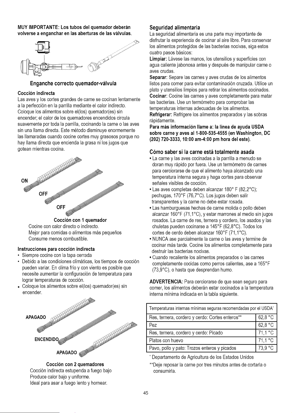
MUY IMPORTANTE: Los tubos del quemador deberan
volverse a enganchar en las aberturas de las valvulas.
Enganche correcto quemador-valvula
Coccion indirecta
Las aves y los cortes grandes de came se cocinan tentamente
a ta perfecci6n en ta parrilIa mediante el cator indirecto.
Cotoque los atimentos sobre el(los) quemador(es) sin
encender; el cator de los quemadores encendidos circuta
suavemente por toda ta parriIIa, cocinando Ia came o Iasaves
sin una llama directa. Este metodo disminuye enormemente
Ias IIamaradas cuando cocine cortes muy grasosos porque no
hay llama directa que encienda la grasa ni los jugos que
gotean mientras cocina.
Coccion con 1 quemador
Cocine con cator directo o indirecto.
Mejor para comidas o atimentos m_s pequeSos
Consume menos combustible.
Instrucciones para coccion indirecta
• Siempre cocine con ta tapa cerrada
• Debido a tas condiciones clim_ticas, los tiempos de cocci6n
pueden variar. En clima frio y con viento es posibte que
necesite aumentar Ia configuraci6n de temperatura para
Iograr temperaturas de cocci6n.
• Cotoque los atimentos sobre el(los) quemador(es) sin
encender.
Seguridad alimentaria
La seguridad atimentaria es una parte muy importante de
disfrutar Ia experiencia de cocinar at aire Iibre. Para conservar
los alimentos protegidos de Ias bacterias nocivas, siga estos
cuatro pasos b_sicos:
Limpiar: L_vese Ias manos, los utensilios y superficies con
agua catiente jabonosa antes y despues de manipular came o
aves crudas.
Separar: Separe Ias carnes y aves crudas de los atimentos
Iistos para comer para evitar contaminaci6n cruzada. Utilice un
plato y utensilios Iimpios para retirar los atimentos cocinados.
Cocinar: Cocine Ias carnes y aves comptetamente para matar
Ias bacterias. Use un term6metro para comprobar Ias
temperaturas internas adecuadas de los atimentos.
Refrigerar: Refrigere los atimentos preparados y Ias sobras
r_pidamente.
Para mas informaci6n Ilame a: la linea de ayuda USDA
sobre came y ayes al 1-800-535-4555 (en Washington, DC
(202) 720-3333, 10:00 am-4:00 pm hora del este).
Como saber si la carne esta totalmente asada
• La came y Ias aves cocinadas a ta parriIIa a menudo se
doran muy r_pido por fuera. Use un term6metro de carnes
para cerciorarse de que el atimento haya atcanzado una
temperatura interna segura y haga cortes para observar
se_ates visibtes de cocci6n.
• Las aves completas deben atcanzar 180° F (82,2°C);
pechugas, 170°F (76,7°C). Los jugos deben salir
transparentes y Ia came no debe estar rosada.
• Las hamburguesas hechas de came motida o polio deben
alcanzar 160°F (71,1°C), y estar marrones at medio sin jugos
rosados. La came de res, ternera y cordero, los asados y Ias
chutetas pueden cocinarse a 145°F (62,8°C). Todos los
cortes de cerdo deben atcanzar 160°F (71,1°C).
• NUNCA ase parciatmente Ia came o Ias aves y termine de
cocinar m_s tarde. Cocine los atimentos completamente para
destruir las bacterias nocivas.
• Cuando recatiente los atimentos preparados o Ias carnes
completamente cocidas como perros calientes, ase a 165°F
(73,9°C), o hasta que desprendan humo.
ADVERTENCIA: Para cerciorarse de que sean seguro para
comer, los alimentos deber_n estar cocinados a ta temperatura
interna minima indicada en la tabta siguiente.
Coccion con 2 quemadores
Cocci6n indirecta estupenda a fuego bajo
Produce cator bajo y uniforme.
Ideal para asar a fuego lento y hornear.
Temperaturasinternasminimassegurasrecomendadasporel USDA*
Res, ternera, cordero y cerdo: Cortes enteros** 62,8 °C
Pez 62,8 °C
Res, ternera, cordero y cerdo: Picado 71,1 °C
Platos con huevo 71,1 °C
Pavo, polio y pato: Trozos enteros y picados 73,9 °C
* Departamento de Agricuttura de los Estados Unidos
**Deje reposar Ia came por tres minutos antes de cortarla o
consumirta.
45
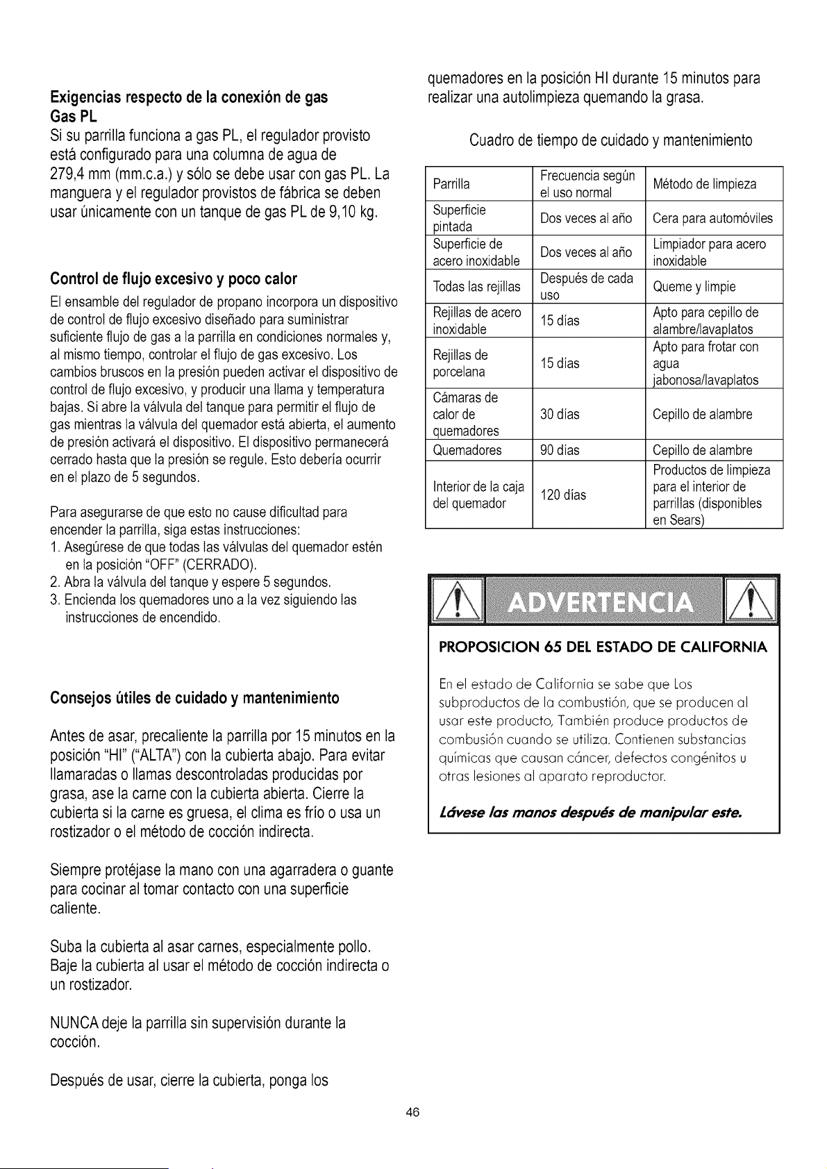
Exigencias respecto de la conexion de gas
Gas PL
Si su parrillafunciona a gas PL, el regulador provisto
esta configurado para una columna de agua de
279,4 mm (mm.c.a.)y s61ose debe usar con gas PL. La
manguera y el regulador provistosde fabrica se deben
usar Qnicamentecon un tanque de gas PL de 9,10 kg.
Control de flujo excesivo y poco calor
El ensambte del regulador de propano incorpora un dispositivo
de control de flujo excesivo disefiado para suministrar
suficiente flujo de gas a ta parrilIa en condiciones normates y,
at mismo tiempo, controtar el flujo de gas excesivo. Los
cambios bruscos en ta presi6n pueden activar el dispositivo de
control de flujo excesivo, y producir una llama y temperatura
bajas. Si abre Ia v_lvuta del tanque para permitir el flujo de
gas mientras Ia v_lvuta del quemador esta abierta, el aumento
de presi6n activara el dispositivo. El dispositivo permanecer_
cerrado hasta que Ia presi6n se regute. Esto deberia ocurrir
en el plazo de 5 segundos.
Para asegurarse de que esto no cause dificuttad para
encender Ia parriIIa, siga estas instrucciones:
1. Asegt_resede que todas Ias v_lvutas del quemador esten
en ta posici6n "OFF" (CERRADO).
2. Abra Ia v_tvuta del tanque y espere 5 segundos.
3. Encienda los quemadores uno a ta vez siguiendo Ias
instrucciones de encendido.
Consejos utiles de cuidado y mantenimiento
Antes de asar, precaliente la parrilla por 15 minutos en la
posici6n "HI" ("ALTA")con la cubierta abajo. Para evitar
Ilamaradas o llamas descontroladas producidaspor
grasa, ase la came con la cubierta abierta. Cierre la
cubierta si la came es gruesa, el clima es frio o usa un
rostizador o el metodo de cocci6n indirecta.
quemadores en la posici6n HI durante 15 minutos para
realizar una autolimpieza quemando la grasa.
Cuadrode tiempo de cuidado y mantenimiento
FrecuenciasegOn M6todode limpieza
Parrilla el uso normal
Superficie Dosveces al afio Cera paraautom6viles
pintada
Superficiede Dosveces al afio Limpiadorparaacero
acero inoxidable inoxidable
Todaslas rejillas Despu6sde cada Quemey limpie
uso
Rejillasde acero 15 dias Apto paracepillo de
inoxidable alambre/lavaplatos
Apto parafrotar con
Rejillasde 15 dias agua
porcelana jabonosa/lavaplatos
Camarasde
calor de 30 dias Cepillode alambre
quemadores
Quemadores 90 dias Cepillode alambre
Productosde limpieza
Interiorde la caja 120dias parael interior de
del quemador parrillas(disponibles
en Sears)
PROPOSICION 65 DEL ESTADO DE CALIFORNIA
Enel estado de California se sabe que Los
subproductos de la combusti6n, que se producen al
usar este producto, Tambi&n produce productos de
combusi6n cuando se utiliza. Contienen substancias
quimicas que causan c6ncer, defectos cong&nitos u
otras lesiones al aparato reproductor.
Ldvese los monos despu#s de monipulor este.
Siempre protejase la mano con una agarradera o guante
para cocinar al tomar contacto con una superficie
caliente.
Suba la cubierta al asar carnes, especialmente polio.
Baje la cubierta al usar el metodo de cocci6n indirecta o
un rostizador.
NUNCA deje la parrilla sin supervisi6n durante la
cocci6n.
Despues de usar, cierre la cubierta, ponga los
46
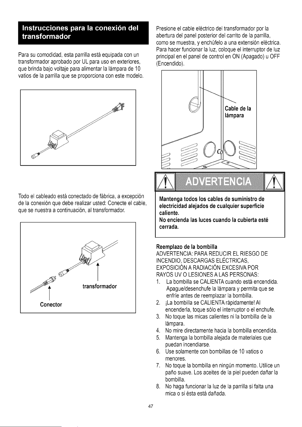
Para su comodidad, esta parrilla esta equipada con un
transformador aprobado por UL para uso en exteriores,
que brinda bajo voltaje para alimentar la lampara de 10
vatios de la parrilla que se proporciona con este modelo.
Presione el cable electrico del transformador por la
abertura del panel posterior del carrito de la parrilla,
como se muestra,y ench0felo a una extensi6n electrica.
Para hacer funcionar la luz, coloque el interruptor de luz
principal en el panel de control en ON (Apagado) u OFF
(Encendido).
Todoel cableado esta conectado de fabrica, a excepci6n
de la conexi6n que debe realizar usted: Conecte el cable,
que se nuestra a continuaci6n, al transformador.
transformador
Conector
Mantenga todos los cables de suministro de
electricidad alejados de cualquier superficie
caliente.
No encienda las luces cuando la cubierta este
cerrada.
Reemplazo de la bombilla
ADVERTENCIA: PARAREDUCIR EL RIESGO DE
INCENDIO, DESCARGAS ELI_CTRICAS,
EXPOSICIONA RADIACION EXCESIVAPOR
RAYOSUV O LESIONESA LAS PERSONAS:
1. La bombilla se CALIENTAcuando esta encendida.
Apague/desenchufe la lampara y permita que se
enfrie antes de reemplazar la bombilla.
2. iLa bombilla se CALIENTA@pidamente!AI
encenderla,toque s61oel interruptor o el enchufe.
3. No toque las micas calientes ni la bombilla de la
lampara.
4. No mire directamentehacia la bombilla encendida.
5. Mantenga la bombilla alejada de materiales que
puedan incendiarse.
6. Use solamente con bombillas de 10 vatios o
menores.
7. No toque la bombilla en ningOnmomento. Utilice un
paso suave. Los aceites de la piel pueden daSar la
bombilla.
8. No haga funcionar la luz de la parrilla si falta una
mica o siesta esta daSada.
47
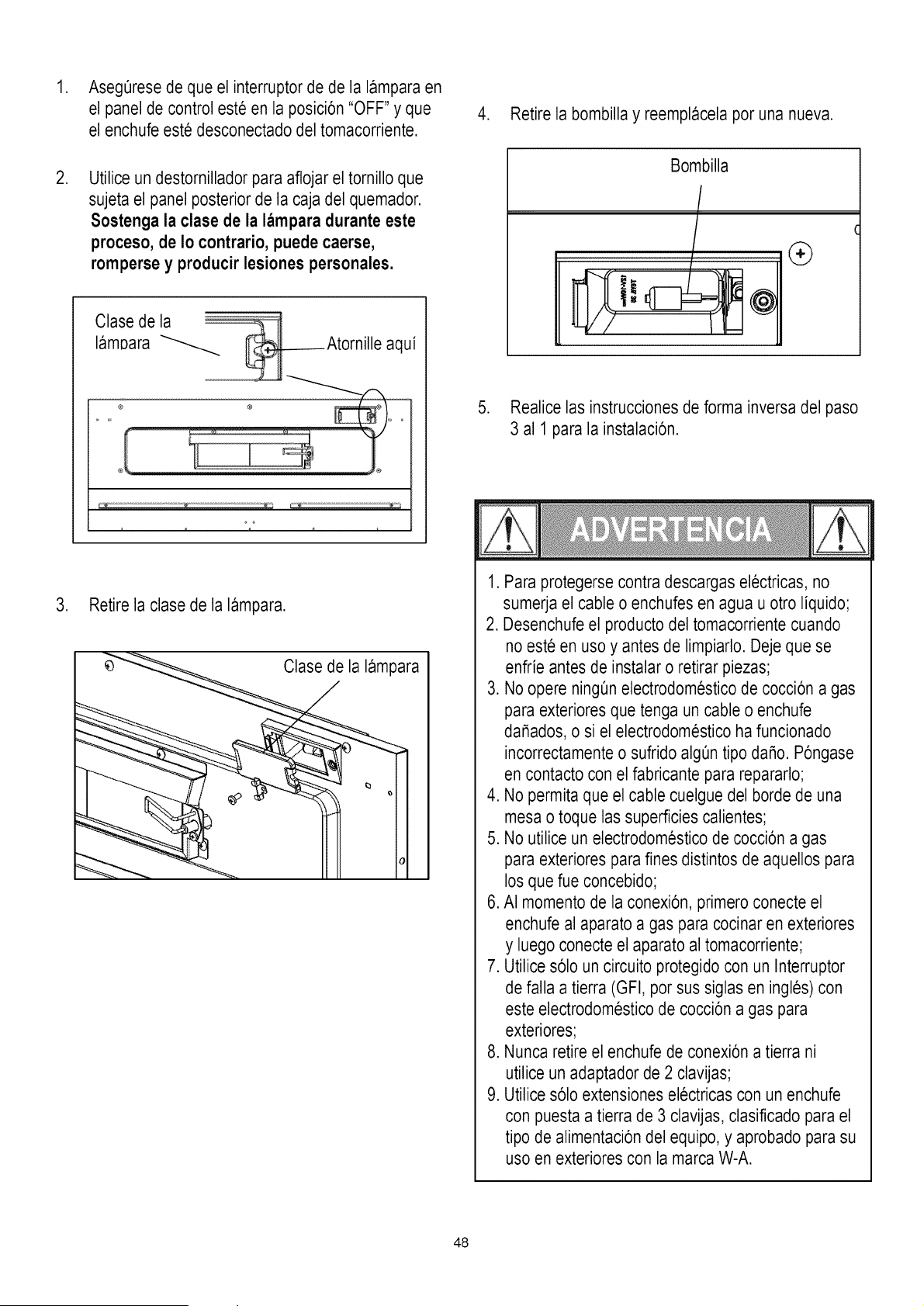
,
,
AsegQresede que el interruptor de de la lampara en
el panel de control este en la posici6n "OFF" y que
el enchufe este desconectado del tomacorriente.
Utilice un destornillador para aflojar el tornillo que
sujeta el panel posterior de la caja del quemador.
Sostenga la clase de la lampara durante este
proceso, de Io contrario, puede caerse,
rompersey producir lesiones personales.
Clase de la _
lamDara _ @Atornille aqui
®
3. Retire la clase de la lampara.
4. Retire la bombilla y reemplacela por una nueva.
,
Bombilla
r
(
®
Realice las instruccionesde forma inversa del paso
3 al 1 para la instalaci6n.
1. Para protegerse contra descargas electricas, no
sumerja el cable o enchufes en agua u otro liquido;
2. Desenchufe el productodel tomacorriente cuando
no este en uso y antes de limpiarlo. Deje que se
enfrie antes de instalar o retirar piezas;
3. No opere ning_n electrodomestico de cocci6n a gas
para exteriores que tenga un cable o enchufe
daSados, o si el electrodomestico ha funcionado
incorrectamente o sufrido algOntipo daSo.P6ngase
en contacto con el fabricante para repararlo;
4. No permita que el cable cuelgue del borde de una
mesa o toque las superficies calientes;
5. No utilice un electrodomesticode cocci6n a gas
para exteriores para fines distintos de aquellos para
los que fue concebido;
6. AI momento de la conexi6n, primero conecte el
enchufe al aparato a gas para cocinar en exteriores
y luego conecte el aparato al tomacorriente;
7. Utilice s61oun circuito protegido con un Interruptor
de falla a tierra (GFI, por sus siglas en ingles) con
este electrodomestico de cocci6n a gas para
exteriores;
8. Nunca retire el enchufe de conexi6n a tierra ni
utilice un adaptador de 2 clavijas;
9. Utilice s61oextensiones electricas con un enchufe
con puesta a tierra de 3 clavijas, clasificado para el
tipo de alimentaci6ndel equipo, y aprobado para su
uso en exteriores con la marca W-A.
48
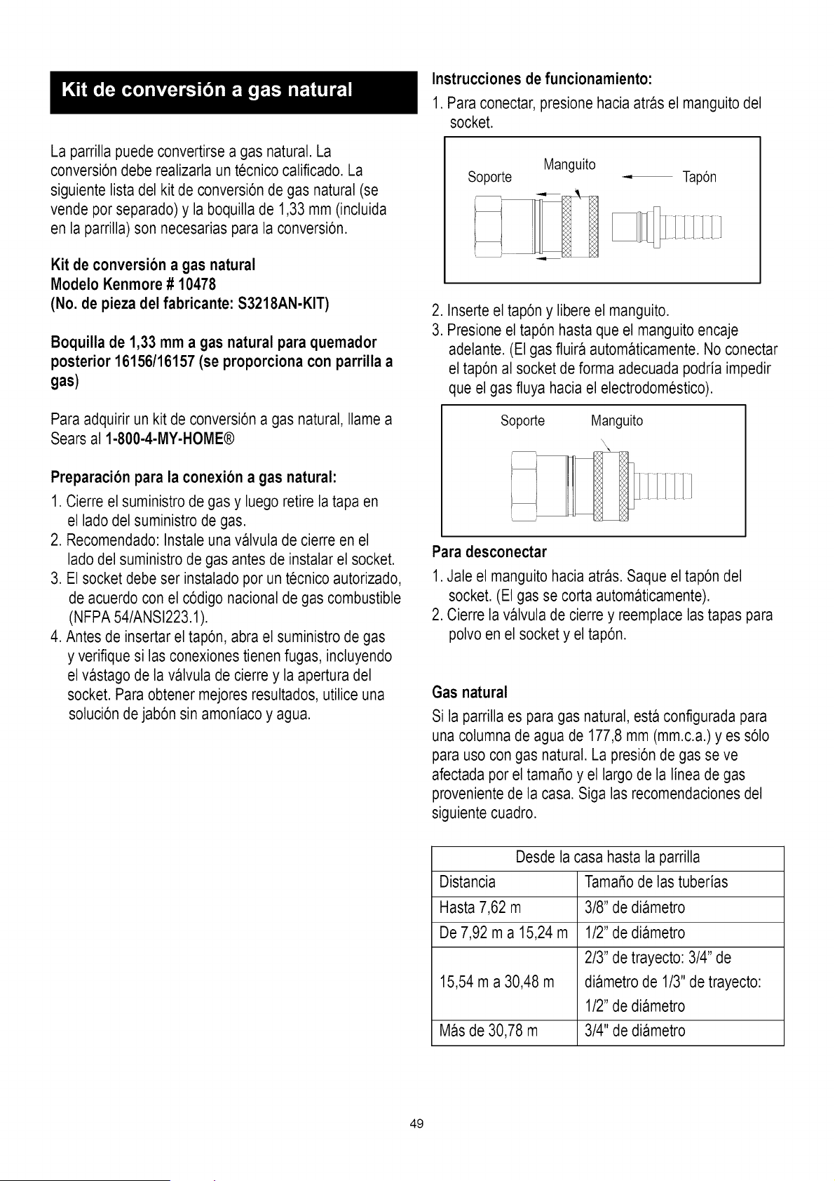
La parrilla puede convertirse a gas natural. La
conversi6n debe realizarla un tecnico calificado. La
siguiente lista del kit de conversi6n de gas natural (se
vende por separado) y la boquilla de 1,33 mm (incluida
en la parrilla) son necesarias para la conversi6n.
Kit de conversion a gas natural
Modelo Kenmore # 10478
(No. de pieza del fabricante: S321SAN-KIT)
Boquilla de 1,33 mm a gas natural para quemador
posterior 16156/16157 (se proporciona con parrilla a
gas)
Para adquirir un kit de conversi6n a gas natural, Ilame a
Sears al 1-800-4-MY-HOME®
Preparacion para la conexion a gas natural:
1. Cierre el suministro de gas y luego retire la tapa en
el ladodel suministro de gas.
2. Recomendado: Instale una valvula de cierre en el
lado del suministro de gas antes de instalar el socket.
3. El socket debe ser instalado por un tecnico autorizado,
de acuerdo con el c6digo nacional de gas combustible
(NFPA 54/ANSI223.1).
4. Antes de insertar el tap6n, abra el suministro de gas
y verifique si las conexiones tienen fugas, incluyendo
el vastago de la valvula de cierre y la apertura del
socket. Para obtener mejores resultados, utilice una
soluci6n de jab6n sin amoniaco y agua.
Instrucciones de funcionamiento:
1. Para conectar, presione hacia atras el manguitodel
socket.
Manguito
Soporte Tap6n
2. Inserte el tap6n y libere el manguito.
3. Presione el tap6n hasta que el manguitoencaje
adelante. (El gas fluira automaticamente. No conectar
el tap6n al socket de forma adecuada podria impedir
que el gas fluya hacia el electrodomestico).
Soporte Manguito
\\
Para desconectar
1. Jale el manguito hacia atras. Saque el tap6n del
socket. (El gas se corta automaticamente).
2. Cierre la valvula de cierre y reemplace las tapas para
polvo en el socket y el tap6n.
Gas natural
Si la parrilla es para gas natural, esta configurada para
una columna de agua de 177,8 mm (mm.c.a.)yes s61o
para uso con gas natural. La presi6n de gas se ve
afectada por el tamaSo y el largo de la linea de gas
provenientede la casa. Siga las recomendaciones del
siguiente cuadro.
Desde la casa hasta la parrilla
Distancia TamaSode las tuberias
Hasta 7,62 m 3/8" de diametro
De 7,92 m a 15,24 m 1/2" de diametro
2/3" de trayecto: 3/4" de
15,54 m a 30,48 m diametro de 1/3" de trayecto:
1/2" de diametro
Mas de 30,78 m 3/4" de diametro
49
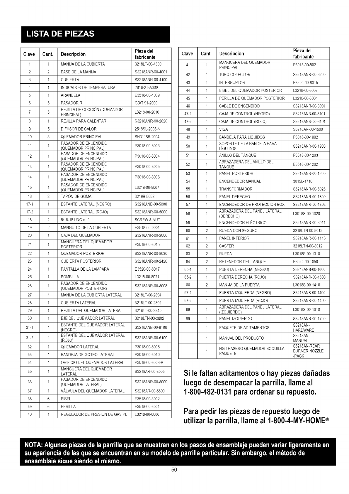
Pieza del
Clave Cant. Descripcion fabricante
I 1 MANIJA DE LA CUBIERTA 3218LT-00-4300
2 2 BASE DE LA MANIJA S3218ANR-00-4001
3 1 CUBIERTA S3218ANR-00-4100
4 1 INDICADOR DE TEMPERATURA 2818-2T-A300
5 1 ARANDELA E3518-00-4009
6 5 PASADOR R GB/T 91-2000
7 3 REJILLA DE COCCION (QUEMADOR L3218-00-2010
PRINCIPAL)
8 1 REJILLA PARA CALENTAR S3218ANR-00-2020
9 5 DIFUSOR DE CALOR 2518SL-2003-N
10 5 QUEMADOR PRINCIPAL SH3118B-2004
PASADOR DE ENCENDIDO
11 1 P3018-00-8003
(QUEMADOR PRINCIPAL)
PASADOR DE ENCENDIDO
12 1 P3018-00-8004
(QUEMADOR PRINCIPAL)
PASADOR DE ENCENDIDO
13 1 P3018-00-8005
(QUEMADOR PRINCIPAL)
PASADOR DE ENCENDIDO
14 1 P3018-00-8006
(QUEMADOR PRINCIPAL)
PASADOR DE ENCENDIDO
15 1 L3218-00-8007
(QUEMADOR PRINCIPAL)
16 2 TAP(}N DE GOMA 3219B-8082
17-I 1 ESTANTE LATERAL (NEGRO) S3218ANB-00-5000
17-2 1 ESTANTE LATERAL (ROJO) S3218ANR-00-5000
18 2 5/16-18 UNC x 1" SCREW& NUT
19 2 MANGUITO DE LA CUBIERTA E3518-00-0001
20 1 CAJA DEL QUEMADOR S3218ANR-00-2000
MANGUERA DEL QUEMADOR
21 1 P3018-00-8015
POSTERIOR
22 1 QUEMADOR POSTERIOR S3218ANR-00-8030
23 1 CUBIERTA POSTERIOR S3218ANR-00-2420
24 1 PANTALLA DE LA LAMPARA E3520-00-8017
25 1 BOMBILLA L3218-00-8021
PASADOR DE ENCENDIDO
26 1 S3218ANR-00-8008
(QUEMADOR POSTERIOR)
27 I MANIJA DE LA CUBIERTA LATERAL 3218LT-00-2804
28 1 CUBIERTA LATERAL 3218LT-00-2802
29 1 REJILLA DEL QUEMADOR LATERAL 3218LT-00-2840
30 1 EJE DEL QUEMADOR LATERAL 3218LTN-00-2802
ESTANTE DEL QUEMADOR LATERAL
31-1 I S3218ANB-00-6100
(NEGRO)
ESTANTE DEL QUEMADOR LATERAL
31-2 I S3218ANR-00-6100
(ROJO)
32 1 QUEMADOR LATERAL P3018-00-8008
33 I BANDEJA DE GOTEO LATERAL P3018-00-6010
34 I ORIFICIO DEL QUEMADOR LATERAL P3018-00-8008-A
MANGUERA DEL QUEMADOR
35 1 S3218AR-00-8005
LATERAL
PASADOR DE ENCENDIDO
36 1 S3218ANR-00-8009
(QUEMADOR LATERAL)
37 1 V/_,LVULADEL QUEMADOR LATERAL S3218AR-00-6600
38 6 BISEL E3518-00-3002
39 6 PERILLA E3518-00-3001
48 1 REGULADOR DE PRESlON DE GAS PL L3218-00-8006
5O
Pieza del
Clave Cant. Descripcibn fabricante
MANGUERA DEL QUEMADOR
41 1 P3018-00-8021
PRINCIPAL
42 I TUBO COLECTOR S3218ANR-00-3200
43 1 INTERRUPTOR E3520-00-8015
44 1 BISEL DEL QUEMADOR POSTERIOR L3218-00-3002
45 I PERILLA DE QUEMADOR POSTERIOR L3218-00-3001
46 I CABLE DE ENCENDIDO S3218ANR-00-8001
47-1 I CAJA DE CONTROL (NEGRO) S3218ANB-00-3101
47-2 I CAJA DE CONTROL (ROJO) S3218ANR-00-3101
48 1 VlGA S3218AR-00-1500
49 1 BANDEJA PARA LJQUIDOS P3018-00-1002
SOPORTE DE LA BANDEJA PARA
50 1 LJQUIDOS S3218ANR-00-1900
51 I ANILLO DEL TANQUE P3018-00-1203
ABRAZADERA DEL ANILLO DEL
52 1 E3518-00-1202
TANQUE
53 1 PANEL POSTERIOR S3218ANR-00-1200
54 1 ENCENDEDOR MANUAL 3019L-1710
55 1 TRANSFORMADOR S3218ANR-00-8023
56 1 PANEL DERECHO S3218ANR-00-1800
57 1 ENCENDEDOR DE PROTECCION BOX S3218ANR-00-1802
ABRAZADERA DEL PANEL LATERAL
58 1 L3018S-00-1020
(DERECHO)
59 1 ENCENDEDOR ELECTRICO S3218ANR-00-8011
60 2 RUEDA CON SEGURO 3218LTN-00-8013
61 1 PANEL INFERIOR S3218ANR-00-1110
62 2 CASTER 3218LTN-00-8012
63 2 RUEDA L3018S-00-1310
64 2 RETENEDOR DEL TANQUE E3520-00-1050
65-I 1 PUERTA DERECHA (NEGRO) S3218ANB-00-1600
65-2 1 PUERTA DERECHA (ROJO) S3218ANR-00-1600
66 2 MANIJA DE LA PUERTA L3018S-00-1410
67-1 I PUERTA IZQUIERDA (NEGRO) S3218ANB-00-1400
67-2 I PUERTA IZQUIERDA (ROJO) S3218ANR-00-1400
ABRAZADERA DEL PANEL LATERAL
68 1 L3018S-00-1010
(IZQUIERDO)
69 1 PANEL IZQUIERDO S3218ANR-00-1700
S3218AN-
I PAQUETE DE ADITAMENTOS
HARDWARE
S3218AN-
I MANUAL DEL PRODUCTO
MANUAL
S3218AN-REAR
NG TRASERO QUEMADOR BOQUILLA
I BURNER NOZZLE
PAQUETE
-PACK
Si le faltan aditamentoso hay piezasdafiadas
luego de desempacarla parrilla, Ilameal
1-800-482-0131para ordenarsu repuesto.
Para pedir las piezasde repuestoluego de
utilizar la parrilla, Ilame al 1-800-4-MY-HOME®
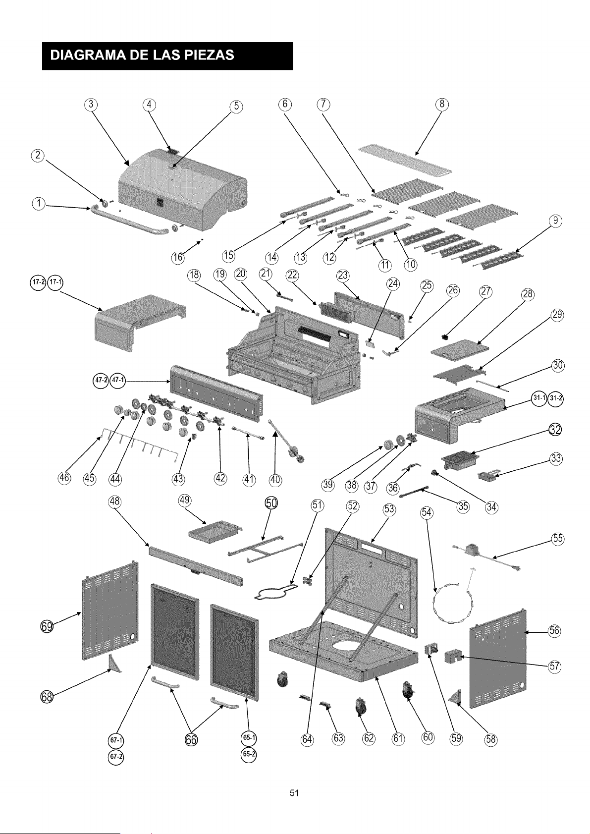
®
@
®®®
@
@
@
\
@
@
@
51
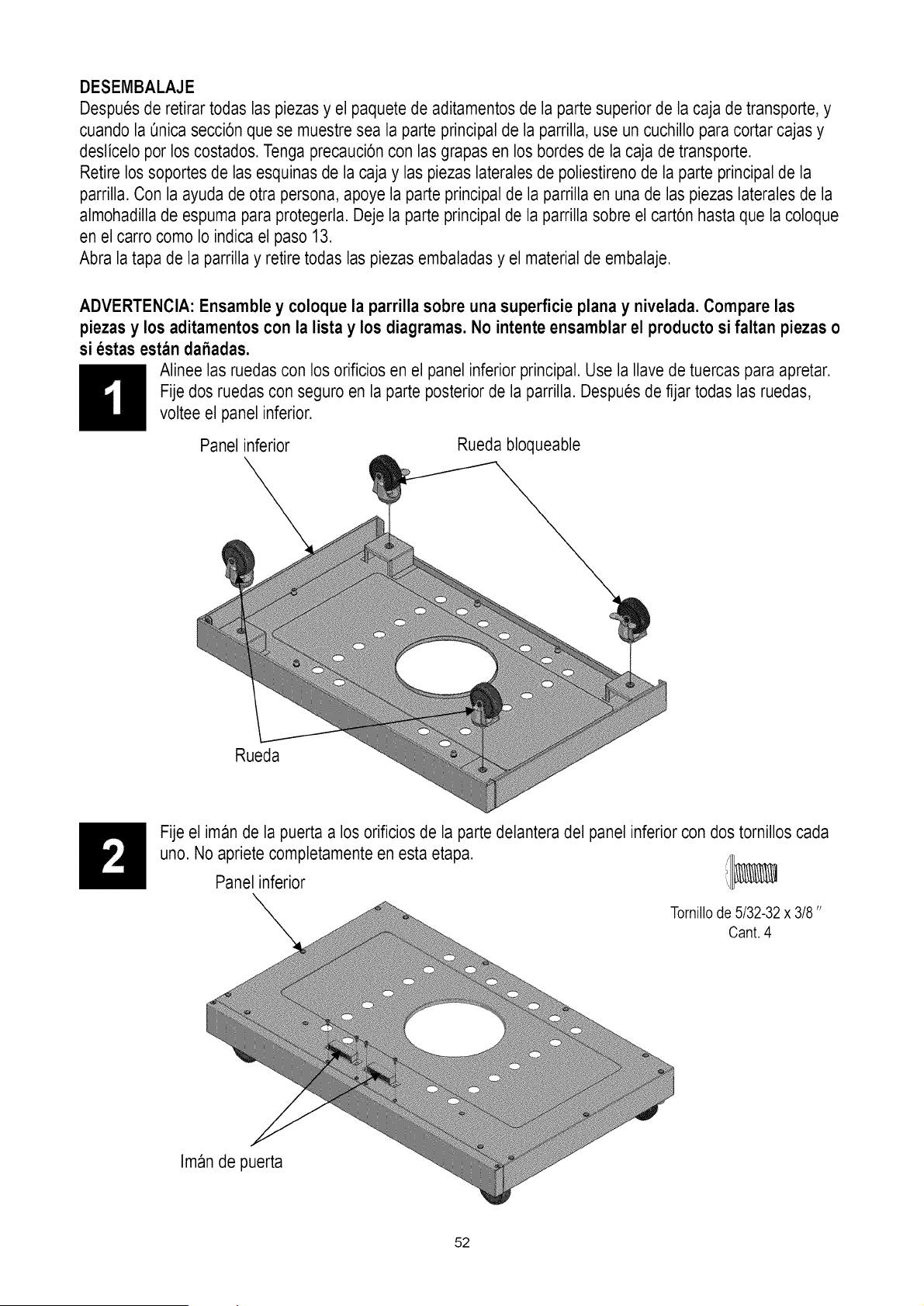
DESEMBALAJE
Despues de retirar todas las piezas y el paquete de aditamentos de la parte superior de la caja de transporte, y
cuando la enica secci6n que se muestre sea la parte principal de la parrilla, use un cuchillo para cortar cajas y
deslicelo por los costados. Tenga precauci6n con las grapas en los bordes de la caja de transporte.
Retire los soportes de las esquinas de la caja y las piezas laterales de poliestireno de la parte principal de la
parrilla. Con la ayuda de otra persona, apoye la parte principal de la parrilla en una de las piezas laterales de la
almohadilla de espuma para protegerla. Deje la parte principal de la parrilla sobre el cart6n hasta que la coloque
en el carro como Io indica el paso 13.
Abra la tapa de la parrilla y retire todas las piezas embaladas y el material de embalaje.
ADVERTENCIA: Ensamble y coloque la parrilla sobre una superficie plana y nivelada. Compare las
piezas y los aditamentos con la lista y los diagramas. No intente ensamblar el producto si faltan piezas o
si estas estan dahadas.
Alinee las ruedas con los orificios en el panel inferior principal. Use la Ilavede tuercas para apretar.
Fije dos ruedas con seguro en la parte posterior de la parrilla. Despues de fijar todas las ruedas,
voltee el panel inferior.
Panel inferior
Rueda bloqueable
Rueda
Fije el iman de la puerta a los orificios de la parte delantera del panel inferior con dos tornillos cada
uno. No apriete completamente en esta etapa. /1_,_
Panel inferior
Tornillode 5/32-32x 3/8"
Cant. 4
Iman de puerta
52
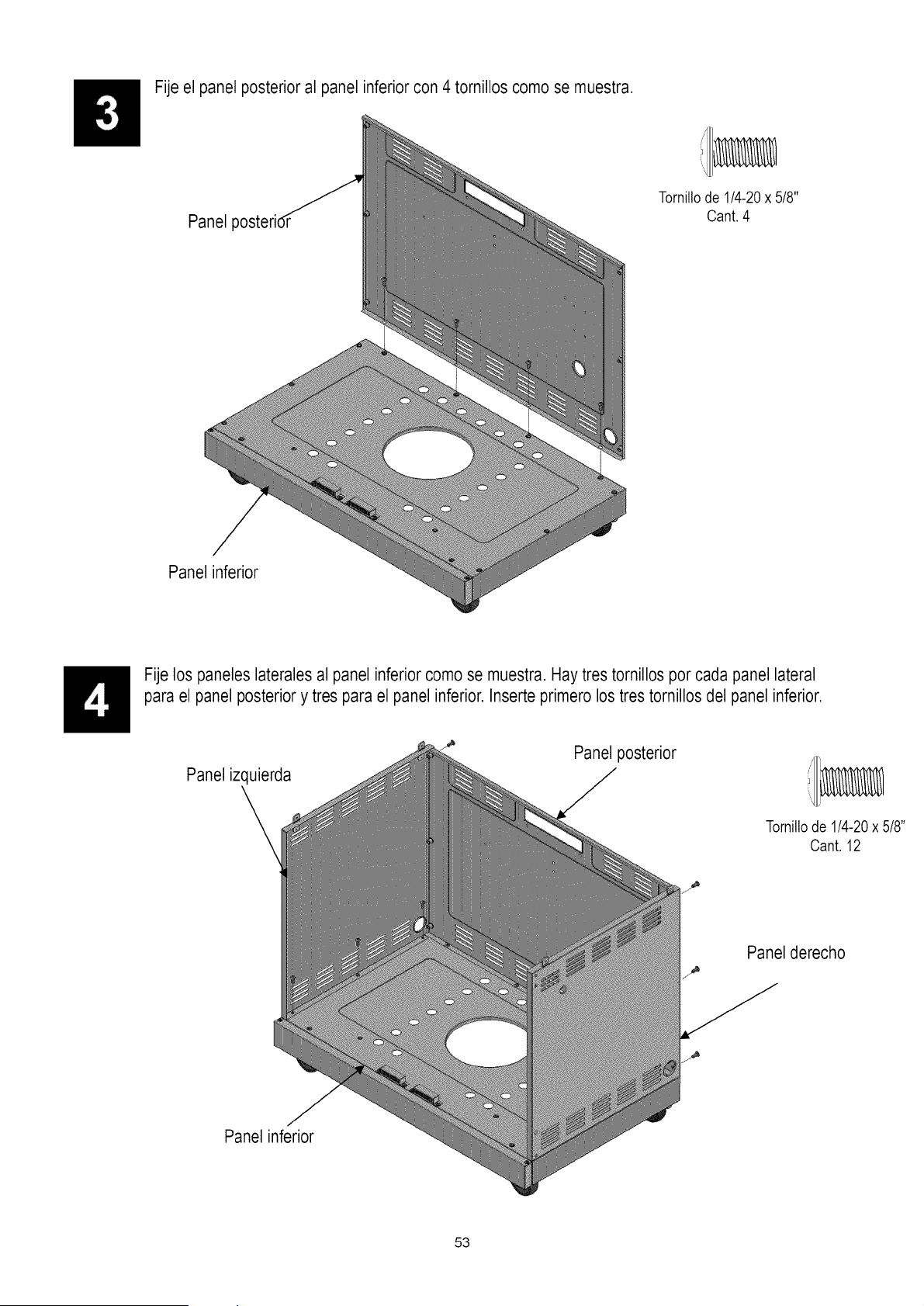
Fije el panel posterior al panel inferior con 4 tornillos como se muestra.
Panel posterid
i/I/
Tornillode1/4-20x 5/8"
Cant.4
Panel inferior
Fije los paneles laterales al panel inferior como se muestra. Hay tres tornillos por cada panel lateral
para el panel posteriory tres para el panel inferior. Inserte primero los tres tornillos del panel inferior.
Panel izquierda
Panel posterior
Tornillode 1/4-20x 5/8"
Cant.12
Panel derecho
Panel inferior
53
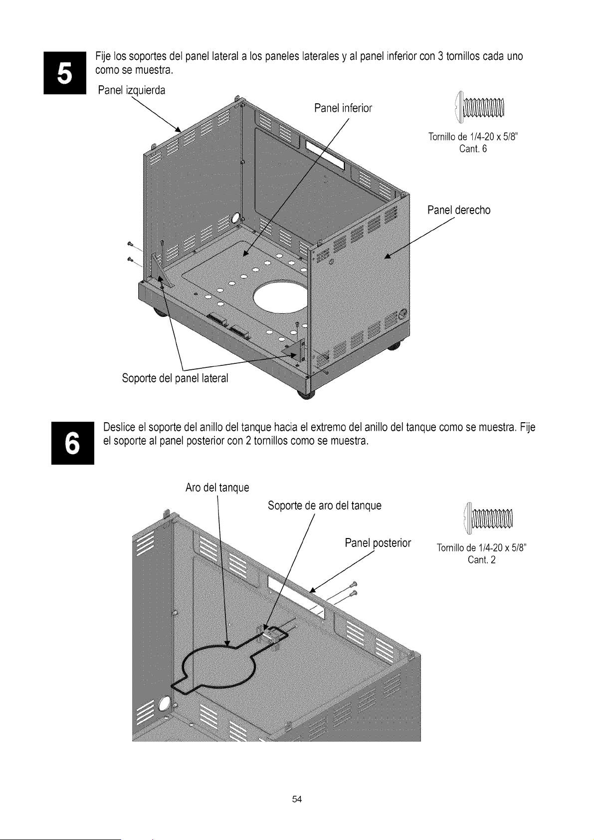
Fije los soportes del panel lateral a los paneles laterales y al panel inferior con 3 tomillos cada uno
como se muestra.
Panel izquierda
Panel inferior
Tornillode 1/4-20x 5/8"
Cant.6
Panel derecho
_L
Soporte del panel lateral
Desliceel soporte del anillo del tanque hacia el extremo del anillo del tanque como se muestra. Fije
el soporte al panel posterior con 2 tornillos como se muestra.
Aro del tanque
Soporte de aro del tanque
Panel posterior
Tornillode 1/4-20x 5/8"
Cant.2
54
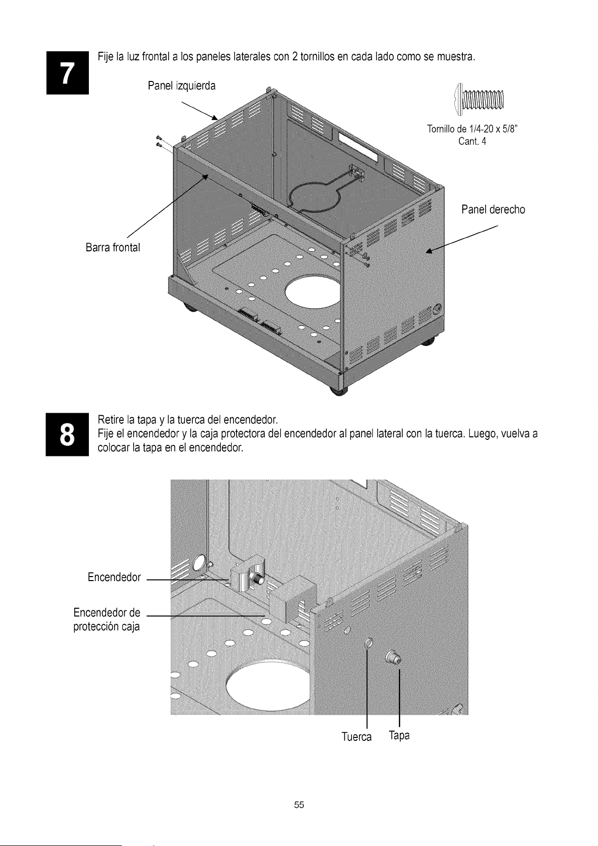
Fije la luz frontal a los paneles laterales con 2 tornillos en cada lado como se muestra.
Panel izquierda i/l_
Tornillode 1/4-20x 5/8"
Cant. 4
Panel derecho
Barra frontal
Retire la tapa y la tuerca del encendedor.
Fije el encendedor y la caja protectora del encendedoral panel lateral con la tuerca. Luego, vuelva a
colocar la tapa en el encendedor.
Encendedor __
Encendedorde
p_tecci6n caja
Tue_a Tapa
55
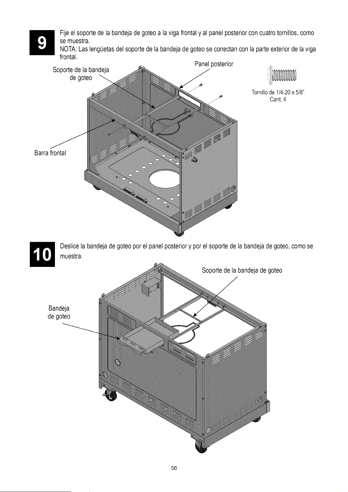
Soporte de la bandeja
de goteo
Fije el soporte de la bandeja de goteo a la viga frontal y al panel posterior con cuatro tornillos, como
se muestra.
NOTA: Las lengeetas del soporte de la bandeja de goteo se conectan con la parte exterior de la viga
frontal.
Panel posterior
Tornillode 1/4-20x 5/8"
Cant.4
Barra frontal
Deslice la bandeja de goteo por el panel posteriory por el soporte de la bandeja de goteo, como se
muestra.
Soporte de la bandeja de goteo
Bandeja
de goteo
56
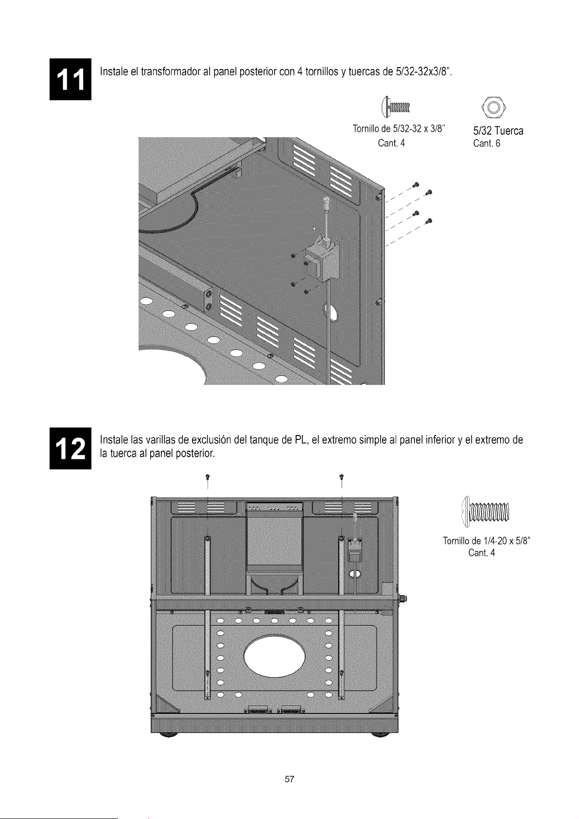
Instale el transformador al panel posterior con 4 tornillos y tuercas de 5/32-32x3/8".
Tornillode5/32-32x 3/8"
Cant.4
5/32 Tuerca
Cant. 6
f
J
./,
./
_J
,,f ._
J. ._
.s
J
Instale las varillas de exclusi6n del tanque de PL, el extremo simple al panel inferiory el extremo de
la tuerca al panel posterior.
Tornillode1/4-20x 5/8"
Cant.4
57
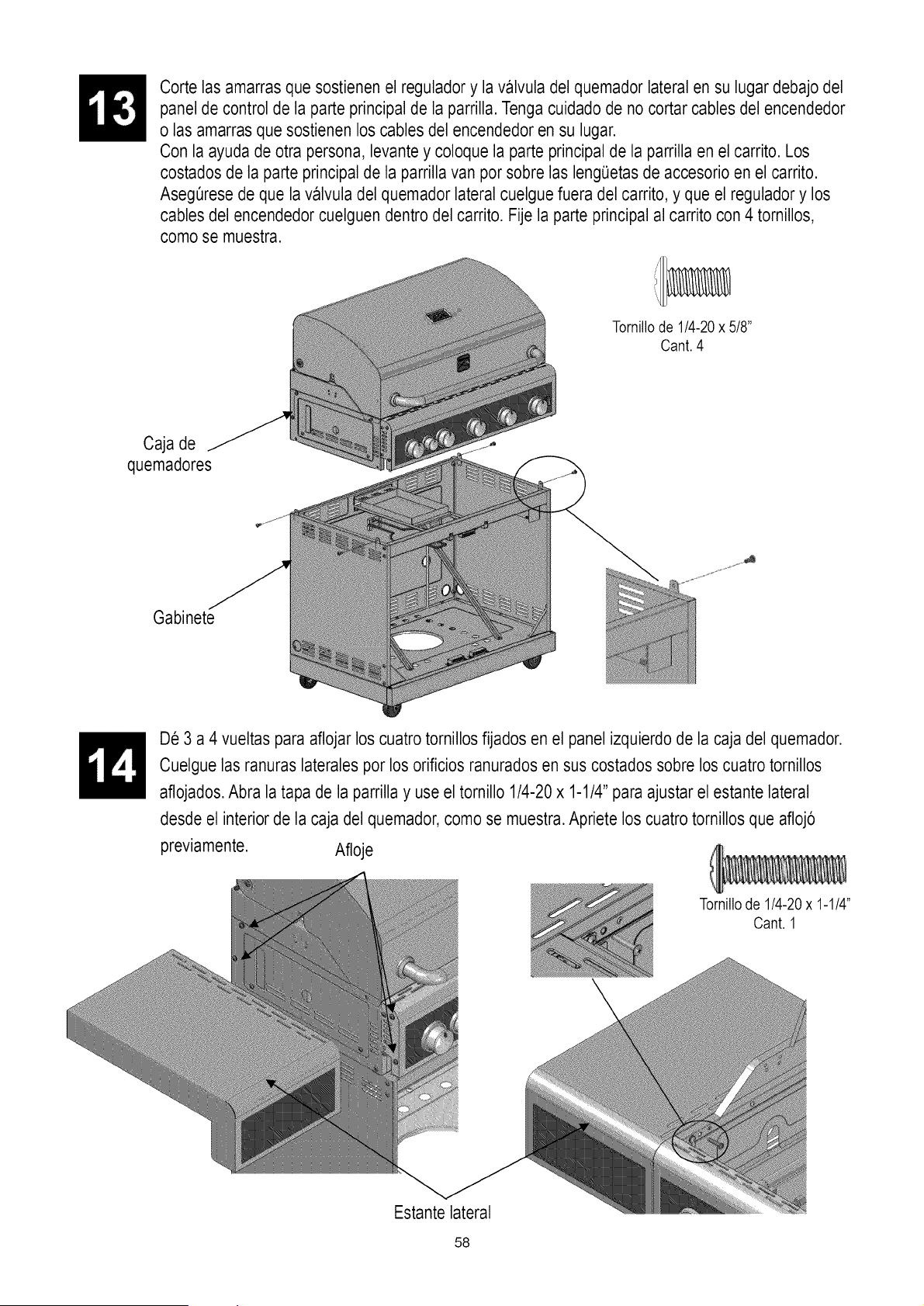
Caja de
quemadores
Corte las amarras que sostienen el regulador y la valvula del quemador lateral en su lugar debajo del
panel de control de la parte principal de la parrilla. Tenga cuidado de no cortar cables del encendedor
o las amarras que sostienen los cables del encendedor en su lugar.
Con la ayuda de otra persona, levante y coloque la parte principal de la parrilla en el carrito. Los
costados de la parte principal de la parrilla van por sobre las leng(Jetasde accesorio en el carrito.
AsegOresede que la valvula del quemador lateral cuelgue fuera del carrito, y que el reguladory los
cables del encendedor cuelguen dentro del carrito. Fije la parte principal al carrito con 4 tornillos,
como se muestra.
Tornillode 1/4-20x 5/8"
Cant.4
Gabinete
De 3 a 4 vueltas para aflojar los cuatro tornillos fijados en el panel izquierdo de la caja del quemador.
Cuelgue las ranuras laterales por los orificios ranurados en sus costados sobre los cuatro tornillos
aflojados.Abra la tapa de la parrilla y use el tornillo 1/4-20 x 1-1/4" para ajustar el estante lateral
desde el interior de la caja del quemador,como se muestra.Apriete los cuatrotornillos que afloj6
previamente. Afloje
Tornillode 1/4-20 x 1-1/4"
Cant. 1
Estantelateral
58
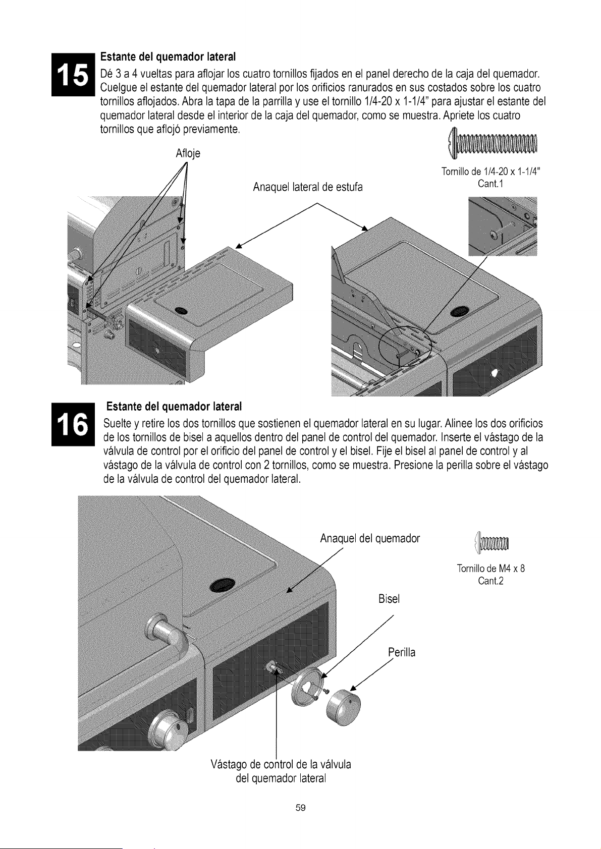
Estante del quemador lateral
De 3 a 4 vueltas para aflojar los cuatro tornillos fljados en el panel derecho de la caja del quemador.
Cuelgue el estante del quemador lateral por los orificios ranuradosen sus costados sobre los cuatro
tornillos aflojados.Abra la tapa de la parrilla y use el tornillo 1/4-20 x 1-1/4" para ajustar el estante del
quemador lateral desde el interior de la caja del quemador,como se muestra.Apriete los cuatro
tornillos que afloj6 previamente.
Afloje
Anaquel lateral de estufa
Tornillode 1/4-20x 1-1/4"
Cant.1
Estante del quemador lateral
Suelte y retire los dos tornillos que sostienen el quemador lateral en su lugar.Alinee los dos orificios
de los tornillos de bisel a aquellos dentro del panel de control del quemador. Inserte el vastago de la
valvula de control por el orificio del panel de control y el bisel. Fije el bisel al panel de control y al
vastago de la valvula de control con 2 tornillos, como se muestra. Presione la perilla sobre el vastago
de la valvula de control del quemador lateral.
Anaquel del quemador
Bisel
TornillodeM4x 8
Cant.2
Perilla
Vastago de co_ltrolde la valvula
del quemador lateral
59
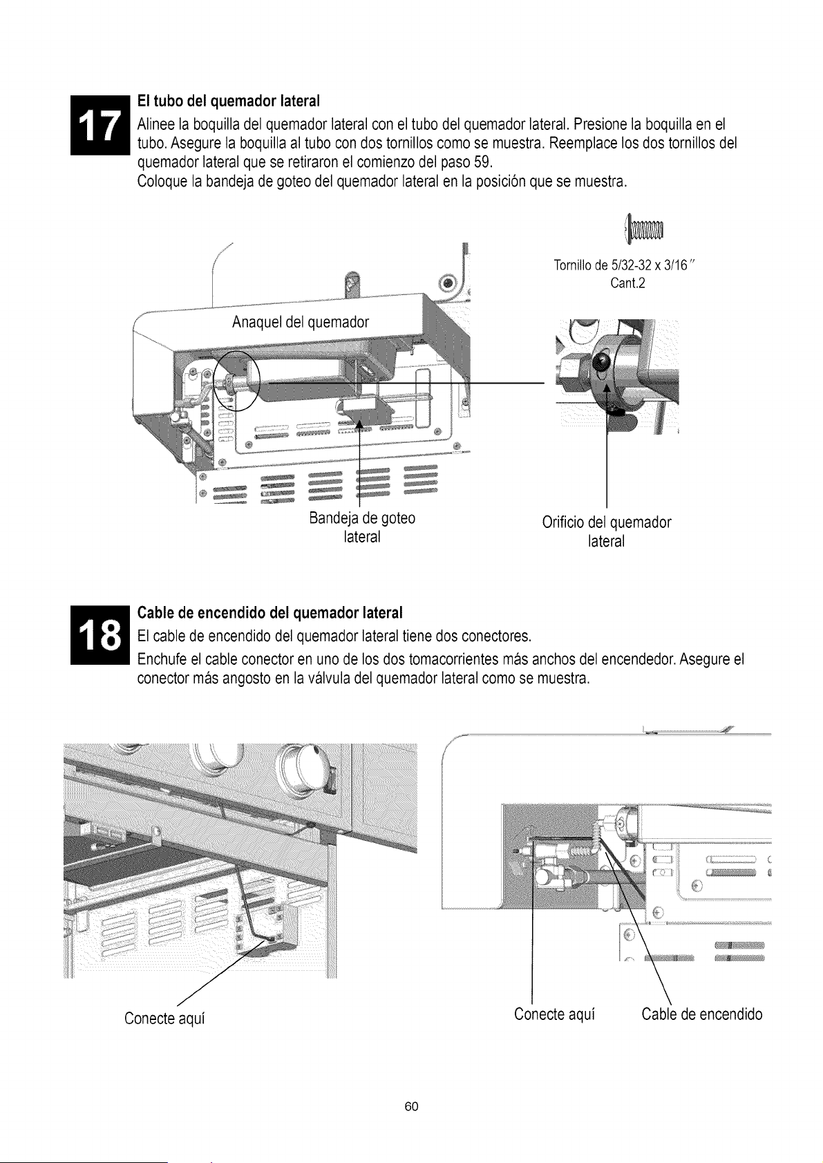
El tubo del quemador lateral
Alinee la boquilla del quemador lateral con el tubo del quemador lateral. Presione la boquilla en el
tubo. Asegure la boquilla al tubo con dos tornillos como se muestra. Reemplace los dos tornillos del
quemador lateral que se retiraron el comienzo del paso 59.
Coloque la bandeja de goteo del quemador lateral en la posici6n que se muestra.
Tornillode5/32-32x 3/16"
Cant.2
Bandeja de goteo Orificio del quemador
lateral lateral
Cable de encendido del quemador lateral
El cable de encendido del quemador lateral tiene dos conectores.
Enchufe el cable conector en uno de los dos tomacorrientes mas anchos del encendedor.Asegure el
conector mas angosto en la valvula del quemador lateral como se muestra.
;!;!;::!_:i_ii_:ii:ii:ii:iiii_:i_ii_ii_ii_!i;!i!!i!!i!!i!!i!!i!i!i!ii!!i!_ii_i!Ii_ ! !i
Conecte aqui
Conecte aqui
Cable de encendido
60
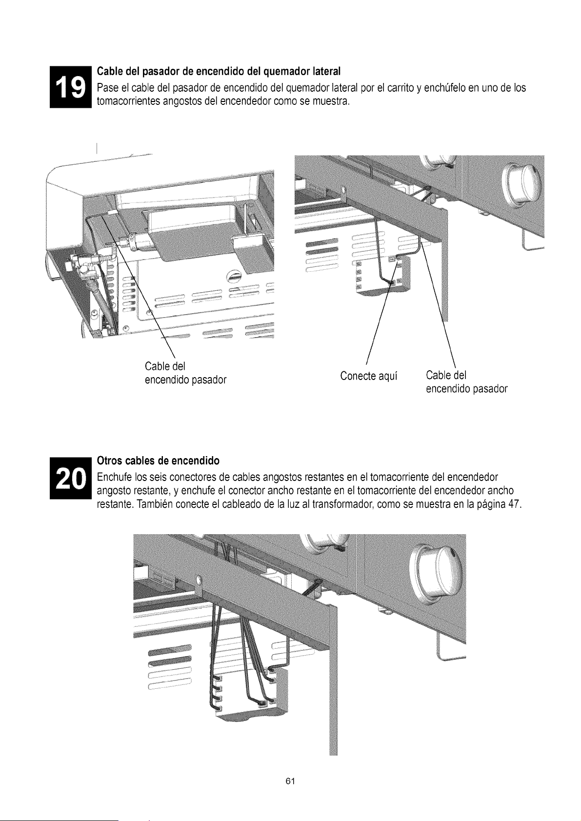
Cable del pasador de encendido del quemador lateral
Pase el cable del pasador de encendido del quemador lateral por el carritoy enchefelo en uno de los
tomacorrientes angostos del encendedor como se muestra.
Cable del
encendido pasador
Conecte aqui
Cable del
encendido pasador
Otros cables de encendido
Enchufe los seis conectores de cables angostos restantes en el tomacorriente del encendedor
angosto restante, y enchufe el conector ancho restante en el tomacorriente del encendedorancho
restante. Tambien conecte el cableado de la luz al transformador,como se muestra en la pagina 47.
61
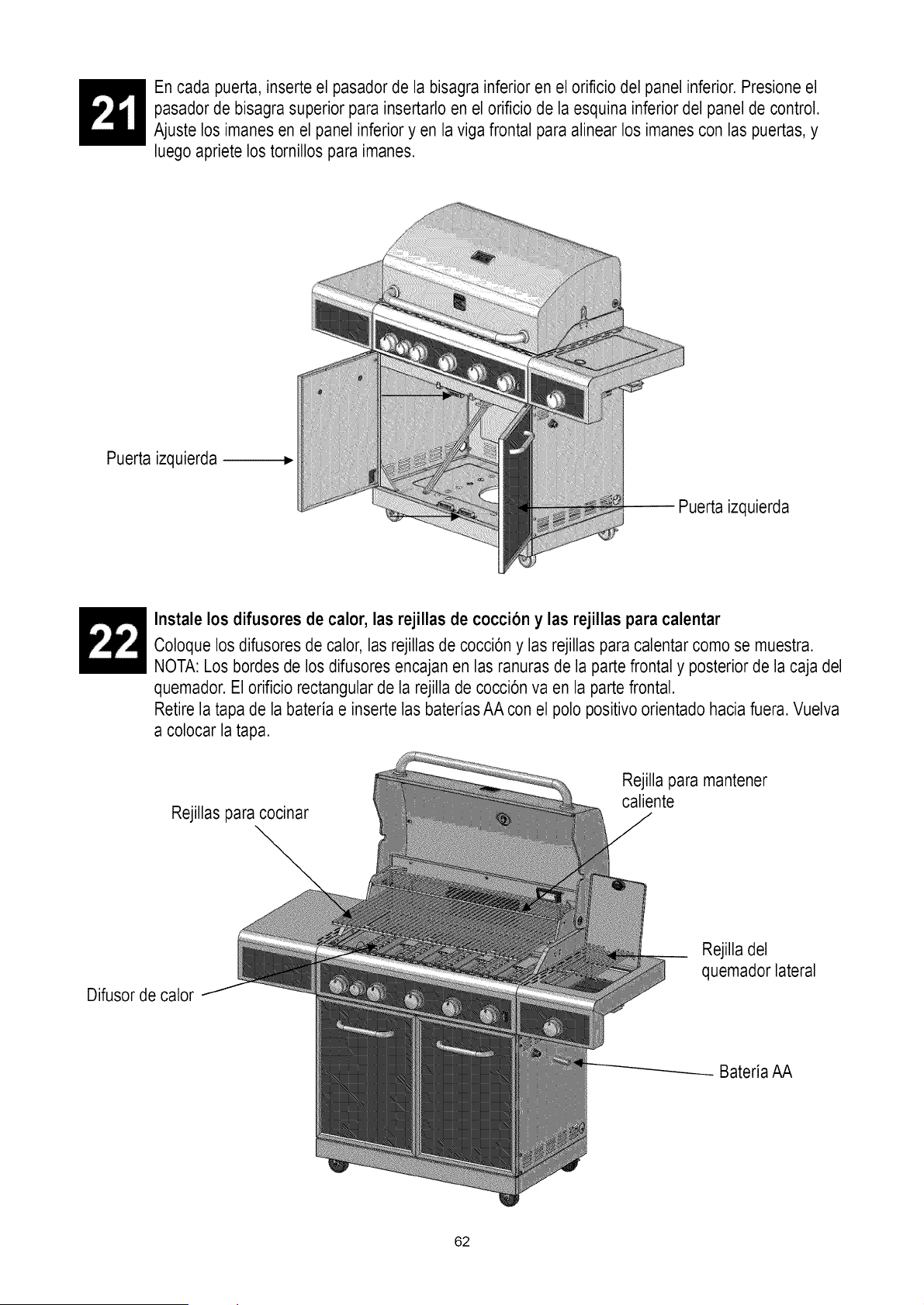
En cada puerta, inserte el pasador de la bisagra inferior en el orificio del panel inferior. Presione el
pasador de bisagra superior para insertarlo en el orificio de la esquina inferior del panel de control.
Ajuste los imanes en el panel inferior y en la viga frontal para alinear los imanes con las puertas, y
luego apriete los tornillos para imanes.
Puerta izquierda
Jerta izquierda
Instale los difusores de calor, las rejillas de coccion y las rejillas para calentar
Coloque los difusores de calor, las rejillas de cocci6n y las rejillas para calentar como se muestra.
NOTA: Los bordes de los difusores encajan en las ranuras de la partefrontal y posteriorde la caja del
quemador. El orificio rectangular de la rejilla de cocci6n va en la parte frontal.
Retire la tapa de la bateria e inserte las baterias AA con el polo positivo orientado hacia fuera. Vuelva
a colocar la tapa.
Rejillas para cocinar
Rejilla para mantener
caliente
Difusor de calor
Rejilla del
quemador lateral
Bateria AA
62
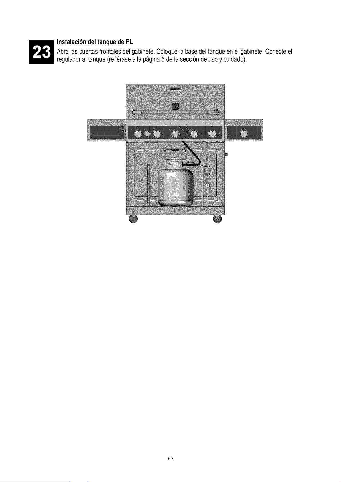
Instalaci6n del tanque de PL
Abra las puertas frontales del gabinete. Coloque la base del tanque en el gabinete. Conecte el
regulador al tanque (refierase a la pagina 5 de la secci6n de uso y cuidado).
63
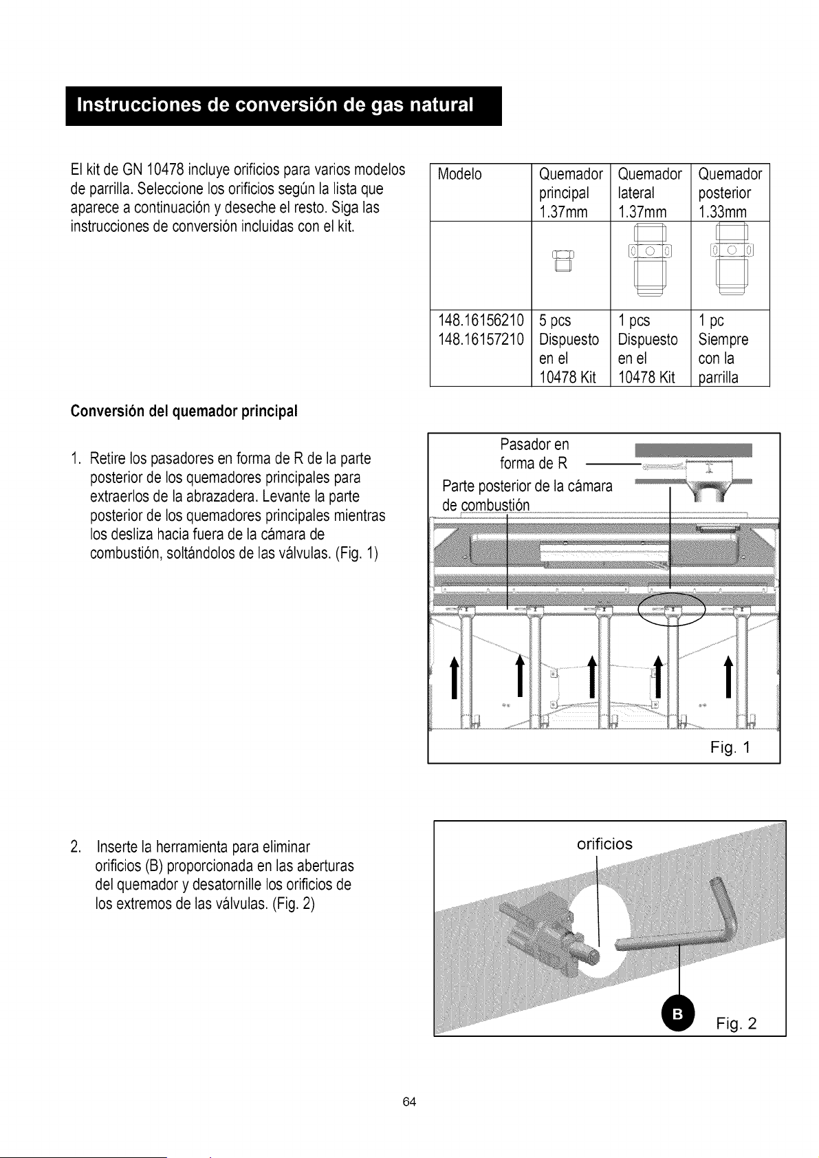
El kit de GN 10478 incluye orificios para varios modelos
de parrilla. Seleccione los orificios segOnla lista que
aparece a continuaci6n y deseche el resto. Siga las
instrucciones de conversi6n incluidas con el kit.
Conversion del quemador principal
.
Retire los pasadores en forma de R de la parte
posteriorde los quemadores principales para
extraerlos de la abrazadera. Levante la parte
posteriorde los quemadores principales mientras
losdesliza hacia fuera de la camara de
combusti6n, soltandolos de las valvulas. (Fig. 1)
Modelo
148.16156210
148.16157210
Quemador
principal
1.37mm
5 pcs
Dispuesto
en el
10478 Kit
Quemador
lateral
1.37mm
1 pcs
Dispuesto
en el
10478Kit
Quemador
posterior
1.33mm
1 pc
Siempre
con la
parrilla
Pasador en
forma de R
Parte posterior de la camara
de combusti6n
Fig. 1
.
Inserte la herramienta para eliminar
oriflcios (B) proporcionada en las aberturas
del quemador y desatornille los orificios de
los extremos de las valvulas. (Fig. 2)
orificios
Fig. 2
64
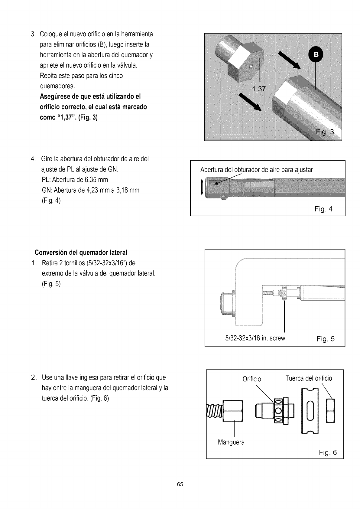
,
Coloque el nuevo orificio en la herramienta
para eliminar orificios (B), luego inserte la
herramienta en la abertura del quemador y
apriete el nuevo oriflcio en la valvula.
Repita este paso para los cinco
quemadores.
Asegt_resede que esta utilizando el
orificio correcto, el cual esta marcado
como "1,37". (Fig. 3)
,
Gire la abertura del obturador de aire del
ajuste de PL al ajuste de GN.
PL: Abertura de 6,35 mm
GN:Abertura de 4,23 mm a 3,18 mm
(Fig. 4)
Abertura del obturador de aire para ajustar
I
Fig. 4
Conversion del quemador lateral
1. Retire 2 tornillos (5/32-32x3/16") del
extremo de la valvula del quemador lateral.
(Fig. 5)
!
i,!
ii........................................................................_S¸
5/32-32x3/16 in. screw
Fig. 5
,
Use una Ilave inglesa para retirar el oriflcio que
hay entre la mangueradel quemador lateral y la
tuerca del orificio. (Fig. 6)
Orificio
\
Manguera
Tuerca del orificio
\
"'%_.,r-
N
H
Fig. 6
65
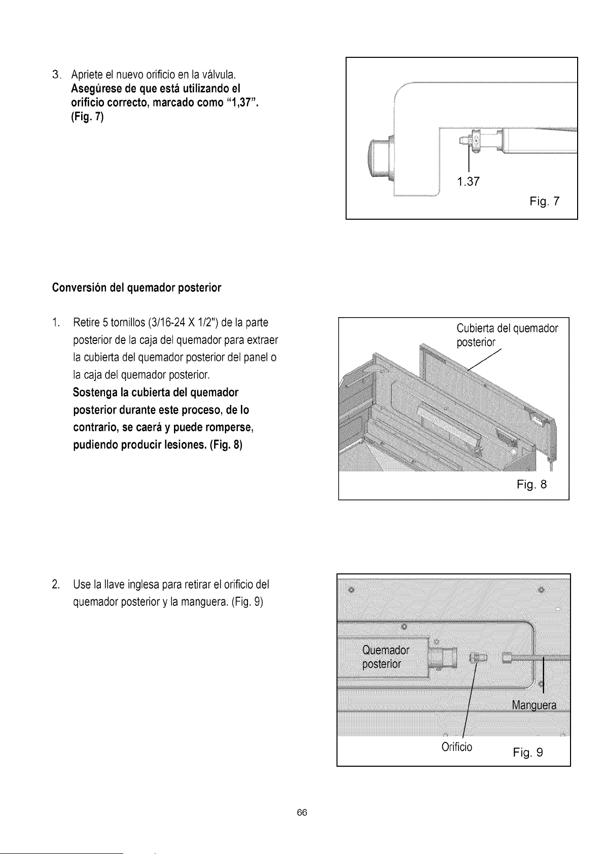
,
Apriete el nuevo oriflcio en la valvula.
Asegurese de que esta utilizando el
orificio correcto, marcado como "1,37".
(Fig. 7)
1.37
Fig. 7
Conversion del quemador posterior
.
Retire 5 tornillos (3/16-24 X 1/2") de la parte
posterior de la caja del quemador para extraer
la cubierta del quemador posterior del panel o
la caja del quemador posterior.
Sostenga la cubierta del quemador
posterior durante este proceso, de Io
contrario, se caera y puede romperse,
pudiendo producir lesiones. (Fig. 8)
Cubierta del quemador
Fig. 8
2. Use la Ilave inglesa para retirar el oriflcio del
quemador posterior y la manguera.(Fig. 9)
Orificio
Fig. 9
66
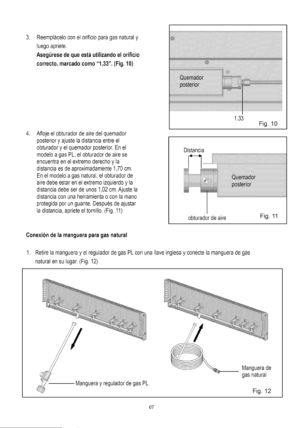
.
.
Reemplacelo con el orificio para gas natural y
luego apriete.
Asegurese de que esta utilizando el orificio
correcto, marcado como "1,33". (Fig. 10)
Afloje el obturador de aire del quemador
posterior y ajuste la distancia entre el
obturador y el quemador posterior. En el
modelo a gas PL, el obturador de aire se
encuentra en el extremo derecho y la
distancia esde aproximadamente 1,70 cm.
En el modelo a gas natural, el obturador de
aire debe estar en el extremo izquierdo y la
distancia debe ser de unos 1,02 cm. Ajuste la
distancia con una herramienta o con la mano
protegida por un guante. Despues de ajustar
la distancia, apriete el tornillo. (Fig. 11)
1.33
Fig. 10
Distancia
-,U
obturador de aire
Fig. 11
Conexion de la manguera para gas natural
1. Retire la mangueray el regulador de gas PL con una Ilave inglesa y conecte la manguerade gas
natural en su lugar. (Fig. 12)
Mangueray regulador de gas PL
Manguera de
gas natural
Fig. 12
67
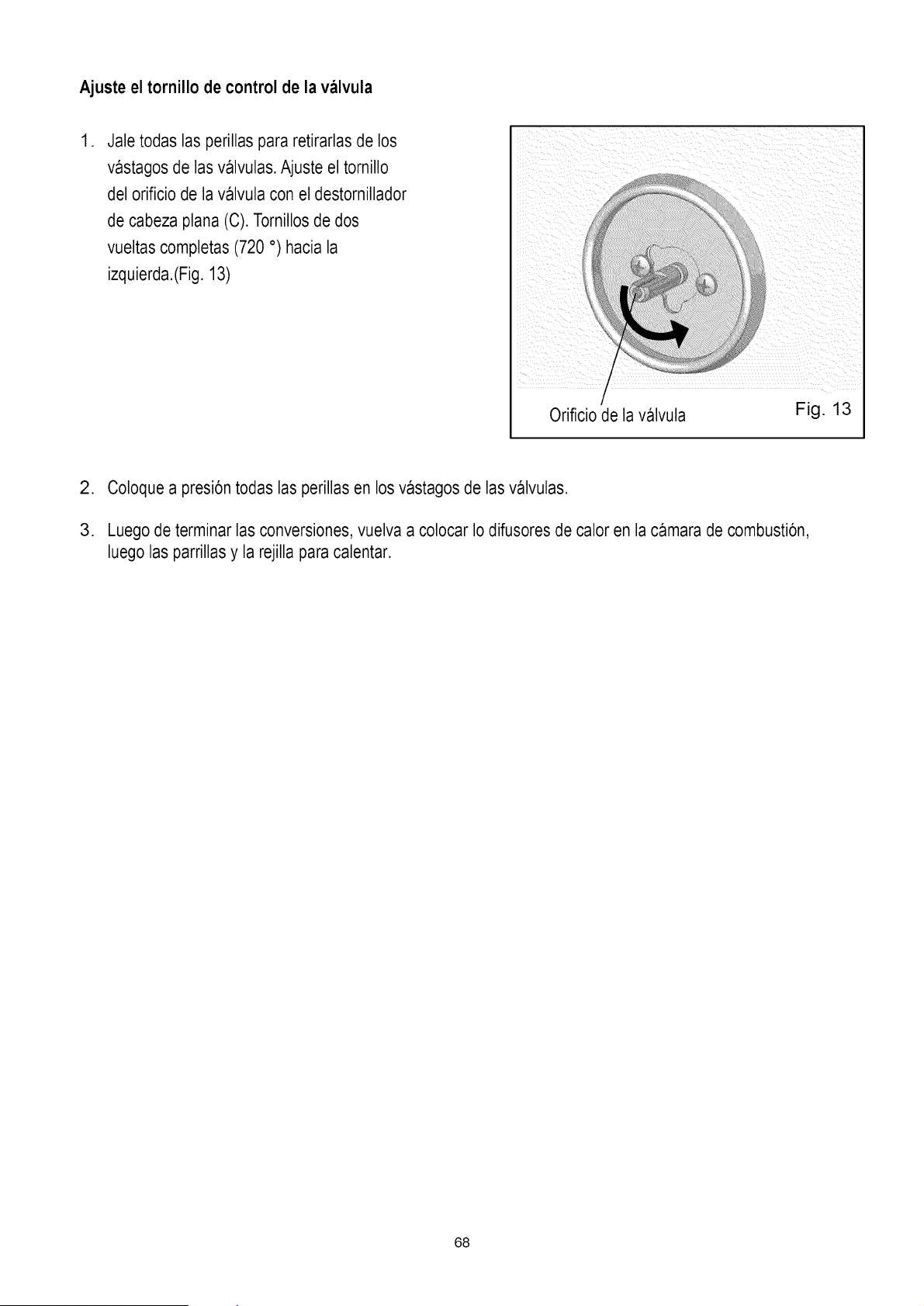
Ajuste el tornillo de control de la valvula
,
Jale todas las perillas para retirarlasde los
vastagos de las valvulas. Ajuste el tornillo
del orificio de la valvula con el destornillador
de cabeza plana (C). Tornillos de dos
vueltas completas (720 °) hacia la
izquierda.(Fig. 13)
I
/
Orificio de la valvula Fig. 13
2. Coloque a presi6n todas las perillas en los vastagos de las valvulas.
3. Luego de terminar las conversiones, vuelva a colocar Io difusores de calor en la camara de combusti6n,
luego las parrillas y la rejilla para calentar.
68
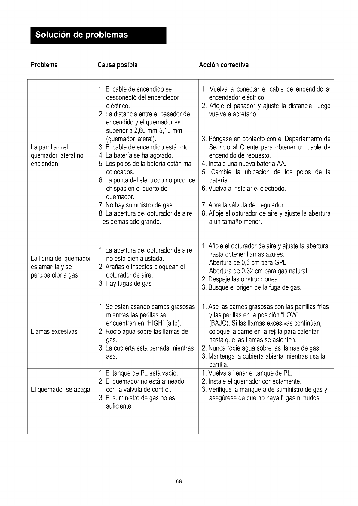
Problema
Causa posible
Accion correctiva
La parrilla o el
quemador lateral no
encienden
La llama del quemador
es amarilla y se
percibe olor a gas
Llamas excesivas
El quemador se apaga
1. El cable de encendido se
desconect6 del encendedor
electrico.
2. La distancia entre el pasadorde
encendido y el quemador es
superior a 2,60 mm-5,10 mm
(quemador lateral).
3. El cable de encendido esta roto.
4. La bateria se ha agotado.
5. Los polos de la bateria estan mal
colocados.
6. La punta del electrodo no produce
chispas en el puerto del
quemador.
7. No hay suministro de gas.
8. La abertura del obturador de aire
es demasiado grande.
1. La abertura del obturador de aire
no esta bien ajustada.
2. AraSaso insectos bloquean el
obturador de aire.
3. Hay fugas de gas
1. Se estan asando carnes grasosas
mientras las perillas se
encuentran en "HIGH" (alto).
2. Roci6 agua sobre las llamasde
gas.
3. La cubierta esta cerrada mientras
asa.
1. El tanque de PL esta vacio.
2. El quemador no esta alineado
con la valvula de control.
3. El suministro de gas no es
suficiente.
1. Vuelva a conectar el cable de encendido al
encendedorelectrico.
2. Afloje el pasador y ajuste la distancia, luego
vuelva a apretarlo.
3. P6ngase en contacto con el Departamentode
Servicio al Cliente para obtener un cable de
encendidode repuesto.
4. Instale una nueva bateria AA.
5. Cambie la ubicaci6n de los polos de la
bated&
6. Vuelva a instalar el electrodo.
7. Abra la valvula del regulador.
8. Afloje el obturador de aire y ajuste la abertura
a un tamaSo menor.
1. Afloje el obturador de aire y ajuste la abertura
hasta obtener llamas azules.
Abertura de 0,6 cm para GPL
Abertura de 0,32 cm para gas natural.
2. Despeje las obstrucciones.
3. Busque el origen de la fuga de gas.
1. Ase las carnes grasosas con las parrillasfrias
y las perillas en la posici6n "LOW"
(BAJO). Si las llamas excesivas continQan,
coloque la came en la rejilla para calentar
hasta que las llamas se asienten.
2. Nunca rocie agua sobre las llamasde gas.
3. Mantenga la cubierta abierta mientras usa la
parrilla.
1. Vuelva a Ilenar el tanque de PL.
2. Instale el quemador correctamente.
3. Verifique la manguerade suministro de gas y
asegQresede que no haya fugas ni nudos.
69
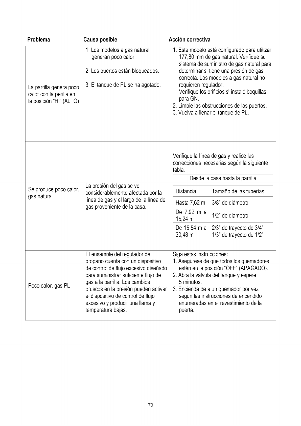
Problema Accion correctiva
La parrillagenera poco
calor con la perilla en
la posici6n "HI" (ALTO)
Se produce poco calor,
gas natural
Poco calor, gas PL
Causa posible
1. Los modelos a gas natural
generan poco calor.
2. Los puertos estan bloqueados.
3. El tanque de PL se ha agotado.
La presi6n del gas se ve
considerablemente afectada por la
linea de gas y el largo de la linea de
gas provenientede la casa.
El ensamble del regulador de
propano cuenta con un dispositivo
de control de flujo excesivo dise_ado
para suministrar suficiente flujo de
gas a la parrilla. Los cambios
bruscos en la presi6n pueden activar
el dispositivo de control de flujo
excesivo y producir una llama y
temperatura bajas.
1. Este modelo esta configurado para utilizar
177,80 mm de gas natural. Verifique su
sistema de suministro de gas natural para
determinarsi tiene una presi6nde gas
correcta. Los modelosa gas natural no
requieren regulador.
Verifique los orificios si instal6 boquillas
para GN.
2. Limpie las obstrucciones de los puertos.
3. Vuelva a Ilenarel tanque de PL.
Verifique la linea de gas y realice las
correcciones necesarias seg0n la siguiente
tabla.
Desde la casa hasta la parrilla
Distancia Tama_o de las tuberias
Hasta 7,62 m 3/8" de diametro
De 7,92 m a
1/2"de diametro
15,24 m
De 15,54 m a 2/3" de trayecto de 3/4"
30,48 m 1/3"de trayecto de 1/2"
Siga estas instrucciones:
1. Aseg0rese de que todos los quemadores
esten en la posici6n "OFF" (APAGADO).
2. Abra la valvula del tanque y espere
5 minutos.
3. Enciendade a un quemador por vez
segQnlas instruccionesde encendido
enumeradas en el revestimiento de la
puerta.
7O
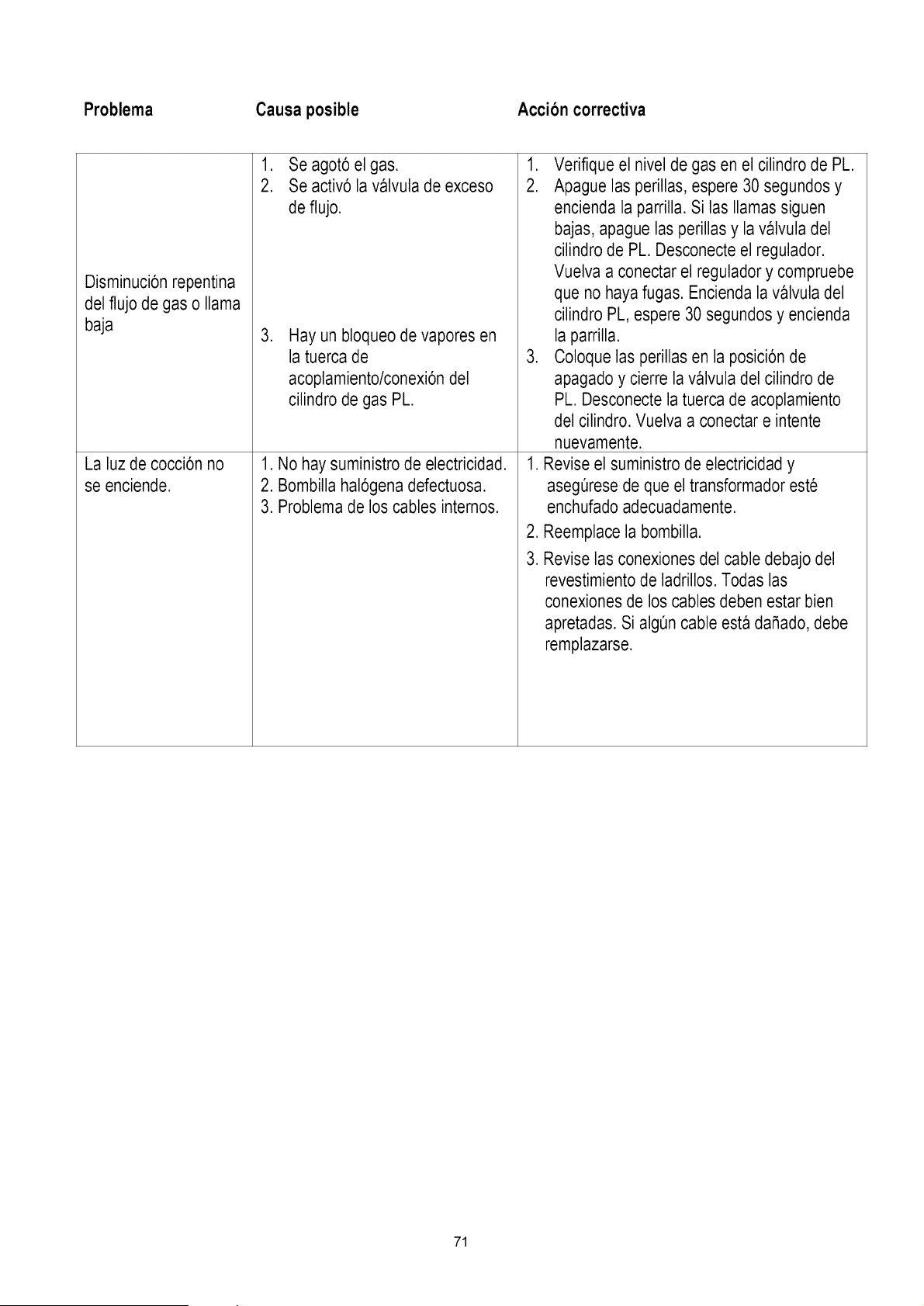
Problema Causa posible Accion correctiva
Disminuci6n repentina
del flujo de gas o llama
baja
1. Se agot6 el gas.
2. Se activ6 la valvula de exceso
de flujo.
,
Hay un bloqueo de vapores en
la tuerca de
acoplamiento/conexi6ndel
cilindro de gas PL.
La luz de cocci6n no
se enciende.
1. No hay suministro de electricidad.
2. Bombilla hal6gena defectuosa.
3. Problemade los cables internos.
1. Verifique el nivel de gas en el cilindro de PL.
2. Apague las perillas, espere 30 segundos y
encienda la parrilla. Si las llamas siguen
bajas, apague las perillas y lavalvula del
cilindro de PL. Desconecte el regulador.
Vuelva a conectar el regulador y compruebe
que no haya fugas. Encienda la valvula del
cilindro PL, espere 30 segundos y encienda
la parrilla.
3. Coloque las perillas en la posici6n de
apagado y cierre la valvula del cilindro de
PL. Desconecte la tuerca de acoplamiento
del cilindro. Vuelva a conectar e intente
nuevamente.
1. Revise el suministro de electricidad y
asegQresede que el transformador este
enchufado adecuadamente.
2. Reemplace la bombilla.
3. Revise las conexiones del cable debajo del
revestimiento de ladrillos. Todas las
conexiones de los cables deben estar bien
apretadas. Si algQncable esta daSado,debe
remplazarse.
71
Your Home
For troubleshooting, product manuals and expert advice:
managemyiife
www.managemylife.com
For repair- in your home - of all major brand appliances,
lawn and garden equipment, or heating and cooling systems,
no matter who made it, no matter who sold it!
For the replacement parts, accessories and
owner's manuals that you need to do-it-yourself.
For Sears professional installation of home appliances
and items like garage door openers and water heaters.
1-800-4-MY-HOME ® (1-800-469-4663)
Call anytime, day or night (U.S.A. and Canada)
www.sears.com www.sears.ca
Our Home
For repair of carry-in items like vacuums, lawn equipment,
and electronics, call anytime for the location of your nearest
Sears Parts & Repair Service Center
1-800-488-1222 (U.S.A.) 1-800-469-4663 (Canada)
www. sears.corn www. sears, ca
To purchase a protection agreement on a product serviced by Sears:
1-800-827-6655 (U.S.A.) 1-800-361-6665 (Canada)
Para pedir servicio de reparacion Au Canada pour service en franqais:
a domicilio, y para ordenar piezas: t-800-LE-FOYER Mc
1-888-SU-HOGAR ® (1-800-533-6937)
www.sears.ca
sears
TM
® Registered Trademark / Trademark of KCD IF', LLC in the United States, or Sears Brands, LLC in other countries
®Marca Registrada / _Mrvlarca de Fabrica de KCD tP, LLC en Estados Unidos, o Sears Brands, LLC in etros paises
MC
Marque d _ commerce / MDMarque deposee de Sears Brands, LLC
72
@