Manual
GENERATOR
CUSTOMER
HELPUNE
HOURS: Non. - Fri. 8 a.m. to 5 p.m. (CT)
1.11PRECAUCI6N
Antes de utilizare]producto,leaeste
manual y siga todas las Reglas de
Seguridad e Instrucciones de Uso.
Sears, Roebuck and Co., Hoffman Estates, _L 60179 U.S.A.
Visit our Craftsman website: www.craftsman.com
Part No. 196822GS Draft 4 (11/08/2005)
o Safety
o Assembly
o Operation
o Maintenance
o Parts
o EspaSol
WARRANTY .................................... 2
SAFETY RULES ............................... 3-4
FEATURES AND CONTROLS ...................... 5
ASSEMBLY ................................... 6-7
OPERATION ................................. 8-11
SPECIFICATIONS ............................... 12
MAINTENANCE .............................. 13o15
STORAGE ..................................... 16
TROUBLESHOOTING ............................ 17
SCHEMATIC DIAGRAM .......................... 18
WIRING DIAGRAM .............................. 19
REPLACEMENT PARTS ....................... 20°28
NOTES ....................................... 29
EMISSION CONTROL WARRANTY .............. 30o31
ESPA!_OL ................................... 32o51
HOW TO ORDER PARTS ................ BACK PAGE
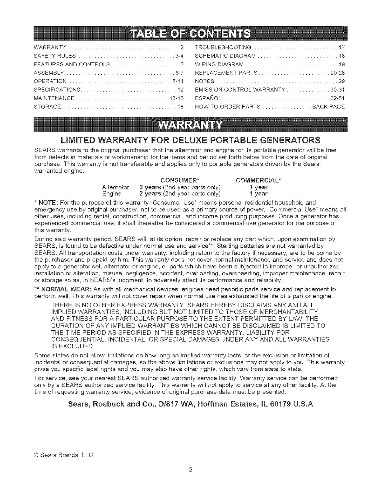
LIMITED WARRANTY FOR DELUXE PORTABLE GENERATORS
SEARS warrants to the original purchaser that the alternator and engine for its portable generator will be free
from defects in materials or workmanship for the items and period set forth below from the date of original
purchase. This warranty is not transferable and applies only to portable generators driven by the Sears
warranted engine.
CONSUMER* COMMERCIAL*
Alternator 2 years (2nd year parts only) 1 year
Engine 2 years (2nd year parts only) 1 year
* NOTE: For the purpose of this warranty "Consumer Use" means personal residential household and
emergency use by original purchaser, not to be used as a primary source of power. "Commercial Use" means all
other uses, including rental, construction, commercial, and income producing purposes. Once a generator has
experienced commercial use, it shall thereafter be considered a commercial use generator for the purpose of
this warranty.
During said warranty period, SEARS will, at its option, repair or replace any part which, upon examination by
SEARS, is found to be defective under normal use and service**. Starting batteries are not warranted by
SEARS. All transportation costs under warranty, including return to the factory if necessary, are to be borne by
the purchaser and prepaid by him. This warranty does not cover normal maintenance and service and does not
apply to a generator set, alternator or engine, or parts which have been subjected to improper or unauthorized
installation or alteration, misuse, negligence, accident, overloading, overspeeding, improper maintenance, repair
or storage so as, in SEARS's judgment, to adversely affect its performance and reliability.
** NORMAL WEAR: As with all mechanical devices, engines need periodic parts service and replacement to
perform well. This warranty will not cover repair when normal use has exhausted the life of a part or engine.
THERE IS NO OTHER EXPRESS WARRANTY. SEARS HEREBY DISCLAIMS ANY AND ALL
IMPLIED WARRANTIES, INCLUDING BUT NOT LIMITED TO THOSE OF MERCHANTABILITY
AND FITNESS FOR A PARTICULAR PURPOSE TO THE EXTENT PERMITTED BY LAW. THE
DURATION OF ANY IMPLIED WARRANTIES WHICH CANNOT BE DISCLAIMED IS LIMITED TO
THE TIME PERIOD AS SPECIFIED IN THE EXPRESS WARRANTY. LIABILITY FOR
CONSEQUENTIAL, INCIDENTAL, OR SPECIAL DAMAGES UNDER ANY AND ALL WARRANTIES
IS EXCLUDED.
Some states do not allow limitations on how long an implied warranty lasts, or the exclusion or limitation of
incidental or consequential damages, so the above limitations or exclusions may not apply to you. This warranty
gives you specific legal rights and you may also have other rights, which vary from state to state.
For service, see your nearest SEARS authorized warranty service facility. Warranty service can be performed
only by a SEARS authorized service facility. This warranty will not apply to service at any other facility. At the
time of requesting warranty service, evidence of original purchase date must be presented.
Sears, Roebuck and Co., Dt817 WA, Hoffman Estates, [L 60179 U.S.A
© Sears Brands, LLC
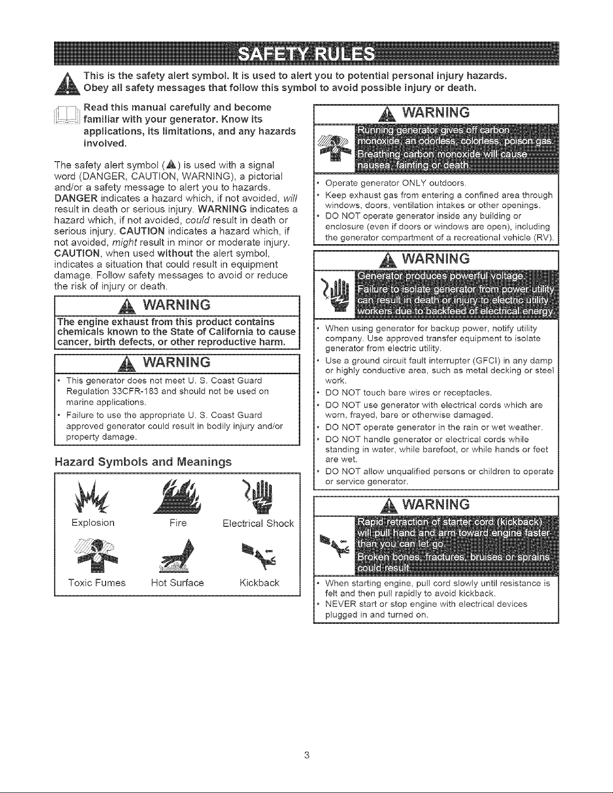
This is the safety alert symbol. It is used to alert you to potentiam personal inju_' hazards.
Obey all safety messages that foltow this symbol to avoid possible injury or death.
ii_!_l;ij Read this manuat carefully and become
familiar with your generator. Know its
applications, its limitations, and any hazards
involved.
The safety alert symbol (,&) is used with a signal
word (DANGER, CAUTION, WARNING), a pictorial
and/or a safety message to alert you to hazards.
DANGER indicates a hazard which, if not avoided, wil/
result in death or serious injury. WARNING indicates a
hazard which, if not avoided, could result in death or
serious injury. CAUTION indicates a hazard which, if
not avoided, might result in minor or moderate injury.
CAUTION, when used without the alert symbol,
indicates a situation that could result in equipment
damage. FoJlow safety messages to avoid or reduce
the risk of injury or death.
WARNING
The engine exhaust from this product contains
chemicams known to the State of California to cause
cancer, birth defects, or other reproductive harm.
WARNING
• This generator does not meet U. S. Coast Guard
Regulation 33CFR-183 and should not be used on
marine applications.
• Failure to use the appropriate U. S. Coast Guard
approved generator could result in bodily injury and/or
property damage.
Hazard Symbols and Meanings
Explosion Fire Electrical Shock
Toxic Fumes Hot Surface Kickback
WARNtNG
Operate generator ONLY outdoors.
Keep exhaust gas from entering a confined area through
windows, doors, ventilation intakes or other openings.
DO NOT operate generator inside any building or
enclosure (even if doors or windows are open), including
the generator compartment of a recreational vehicle (RV).
WARNING
When using generator for backup power, notify utility
company. Use approved transfer equipment to isolate
generator from electric utility.
Use a ground circuit fault interrupter (GFCI) in any damp
or highly conductive area, such as metal decking or steel
work.
DO NOT touch bare wires or receptacles.
DO NOT use generator with electrical cords which are
worn, frayed, bare or otherwise damaged.
DO NOT operate generator in the rain or wet weather.
DO NOT handle generator or electrical cords while
standing in water, while barefoot, or while hands or feet
are wet.
DO NOT allow unqualified persons or children to operate
or service generator.
WARNtNG
When starting engine, pull cord slowly until resistance is
felt and then pull rapidly to avoid kickback.
NEVER start or stop engine with electrical devices
plugged in and turned on.
WARNING
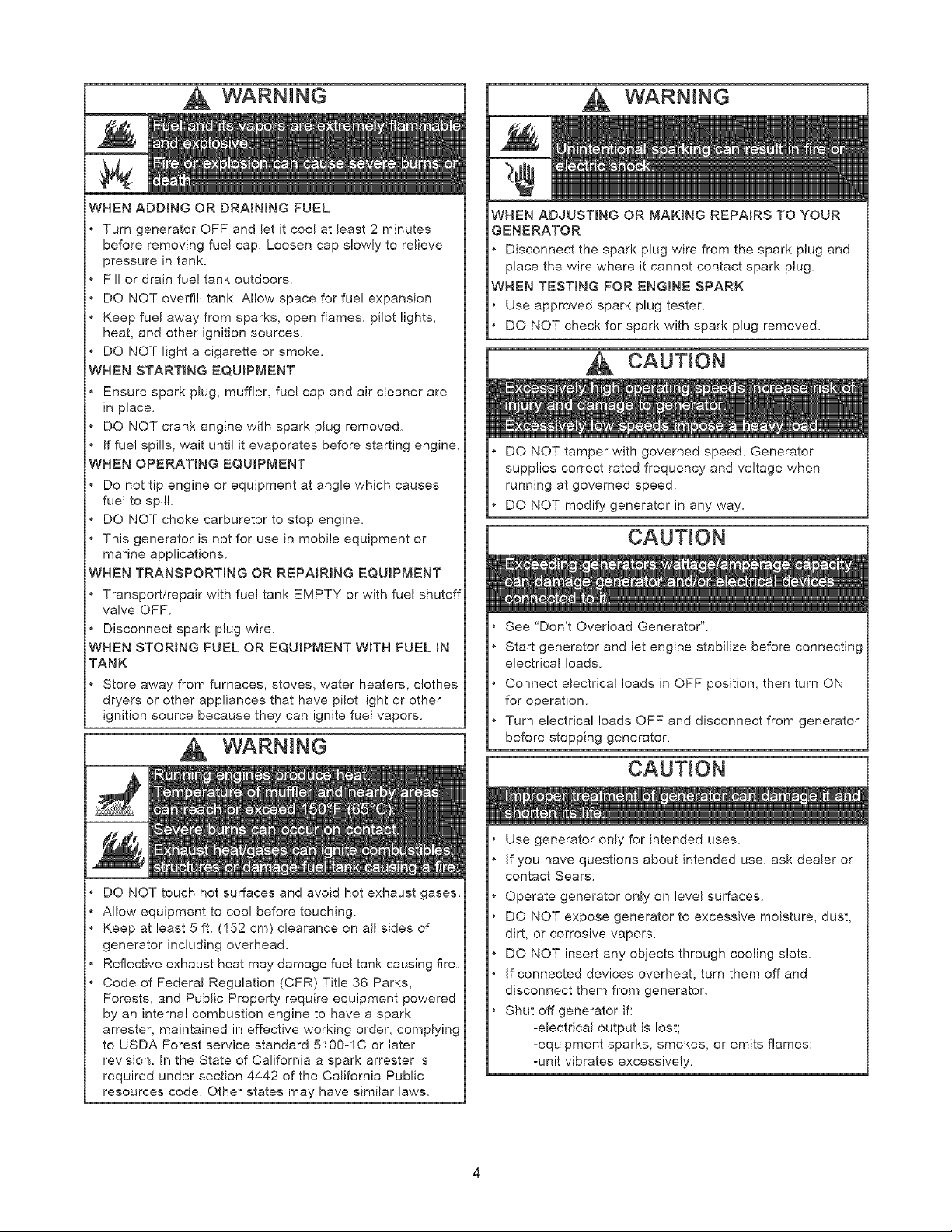
WHEN ADDING OR DRAINmNG FUEL
Turn generator OFF and let it cool at least 2 minutes
before removing fuel cap. Loosen cap slowly to relieve
pressure in tank.
Fill or drain fue! tank outdoors.
DO NOT overfill tank. Allow space for fuel expansion.
Keep fuel away from sparks, open flames, pilot lights,
heat, and other ignition sources.
DO NOT light a cigarette or smoke.
WHEN STARTING EQUIPMENT
Ensure spark plug, muffler, fuel cap and air cleaner are
in place.
DO NOT crank engine with spark plug removed.
If fue! spills, wait until it evaporates before starting engine.
WHEN OPERATING EQUIPMENT
Do not tip engine or equipment at angle which causes
fuel to spill.
DO NOT choke carburetor to stop engine.
This generator is not for use in mobile equipment or
marine applications.
WHEN TRANSPORTmNG OR REPAIRING EQUIPMENT
Transport/repair with fuel tank EMPTY or with fuel shutof
valve OFF.
Disconnect spark plug wire.
WHEN STORBNG FUEL OR EQUIPMENT WITH FUEL IN
TANK
Store away from furnaces, stoves, water heaters, clothes
dryers or other appliances that have pilot light or other
ignition source because they can ignite fuel vapors.
WARNING
DO NOT touch hot surfaces and avoid hot exhaust gases.
Allow equipment to cool before touching.
Keep at least 5 ft. (152 cm) clearance on all sides of
generator including overhead.
Reflective exhaust heat may damage fuel tank causing fire.
Code of Federal Regulation (CFR) Title 36 Parks,
Forests, and Public Property require equipment powered
by an internal combustion engine to have a spark
arrester, maintained in effective working order, complying
to USDA Forest service standard 5100-1C or later
revision. In the State of California a spark arrester is
required under section 4442 of the California Public
resources code. Other states may have similar laws.
WARNING
WHEN ADJUSTmNG OR MAKING REPAIRS TO YOUR
GENERATOR
* Disconnect the spark plug wire from the spark plug and
place the wire where it cannot contact spark plug.
WHEN TESTING FOR ENGINE SPARK
Use approved spark plug tester.
DO NOT check for spark with spark plug removed.
CAUTION
DO NOT tamper with governed speed. Generator
supplies correct rated frequency and voltage when
running at governed speed.
DO NOT modify generator in any way.
CAUTION
See "Don't Overload Generator".
Start generator and let engine stabilize before connecting
electrical loads.
Connect electrical loads in OFF position, then turn ON
for operation.
Turn electrical loads OFF and disconnect from generator
before stopping generator.
CAUTION
Use generator only for intended uses.
If you have questions about intended use, ask dealer or
contact Sears.
Operate generator only on level surfaces.
DO NOT expose generator to excessive moisture, dust,
dirt, or corrosive vapors.
DO NOT insert any objects through cooling slots.
If connected devices overheat, turn them off and
disconnect them from generator.
Shut off generator if:
-electrical output is lost;
-equipment sparks, smokes, or emits flames;
-unit vibrates excessively.
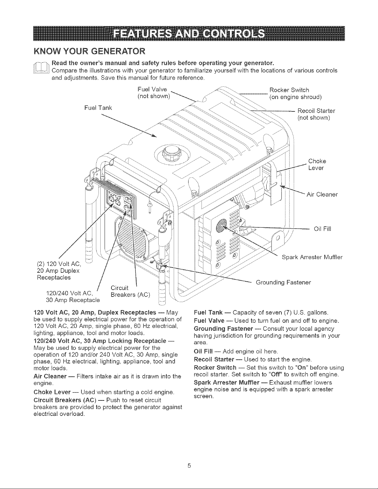
KNOW YOUR GENERATOR
_Read the owner's manua{ and safety rules before operating your generator,
....... Compare the illustrations with your generator to familiarize yourself with the locations of various controls
and adjustments. Save this manual for future reference.
Fuel Valve
(not shown)_./)
Fuel Tank
Rocker Switch
(on engine shroud)
Recoil Starter
(not shown)
Choke
Lever
i
Cleaner
Oil Fill
(2) 120 Volt AC,
20 Amp Duplex
Receptacles /
120/240 Volt AC,
30 Amp Receptacle
Circuit
Breakers (AC)
120 Volt AC, 20 Amp, Duplex Receptacles -- May
be used to supply electrical power for the operation of
120 Volt AC, 20 Amp, single phase, 60 Hz electrical,
lighting, appliance, tool and motor loads.
1201240 Volt AC, 30 Amp Locking Receptacle --
May be used to supply electrical power for the
operation of 120 and/or 240 Volt AC, 30 Amp, single
phase, 60 Hz electrical, lighting, appliance, tool and
motor loads.
Air Cleaner -- Filters intake air as it is drawn into the
engine.
Choke Lever -- Used when starting a cold engine.
CircuEt Breakers (AC) -- Push to reset circuit
breakers are provided to protect the generator against
electrical overload.
Spark Arrester Muffler
Grounding Fastener
Fue_ Tank -- Capacity of seven (7) U.S. gallons.
Fuel Valve -- Used to turn fuel on and off to engine.
Grounding Fastener -- Consult your local agency
having jurisdiction for grounding requirements in your
area.
Oil Fill -- Add engine oil here.
Recoil Starter -- Used to start the engine.
Rocker Switch -- Set this switch to "On" before using
recoil starter. Set switch to "Off" to switch off engine.
Spark Attester Muffler- Exhaust muffler lowers
engine noise and is equipped with a spark attester
screen.
ASSEMBLY
Your Craftsman generator requires some assembly
and is ready for use only after it has been properly
serviced with the recommended oil and fuel.
If you have any problems with the assembly of
your generator, please call the generator helpline
at 1-800-222-3136.
Unpacking the Generator
1. Set the carton on a rigid flat surface.
2. Remove everything from carton except generator.
3. Open carton completely by cutting each corner
from top to bottom.
4. Leave generator on carton to install wheel kit.
Carton Contents
Check all contents. If any parts are missing or damaged,
call the generator helpline at 1-800-222-3136.
The generator
Owner's manual
Engine oil
120/240 Volt, 30 Amp locking plug
Wheel kit
Battery charger
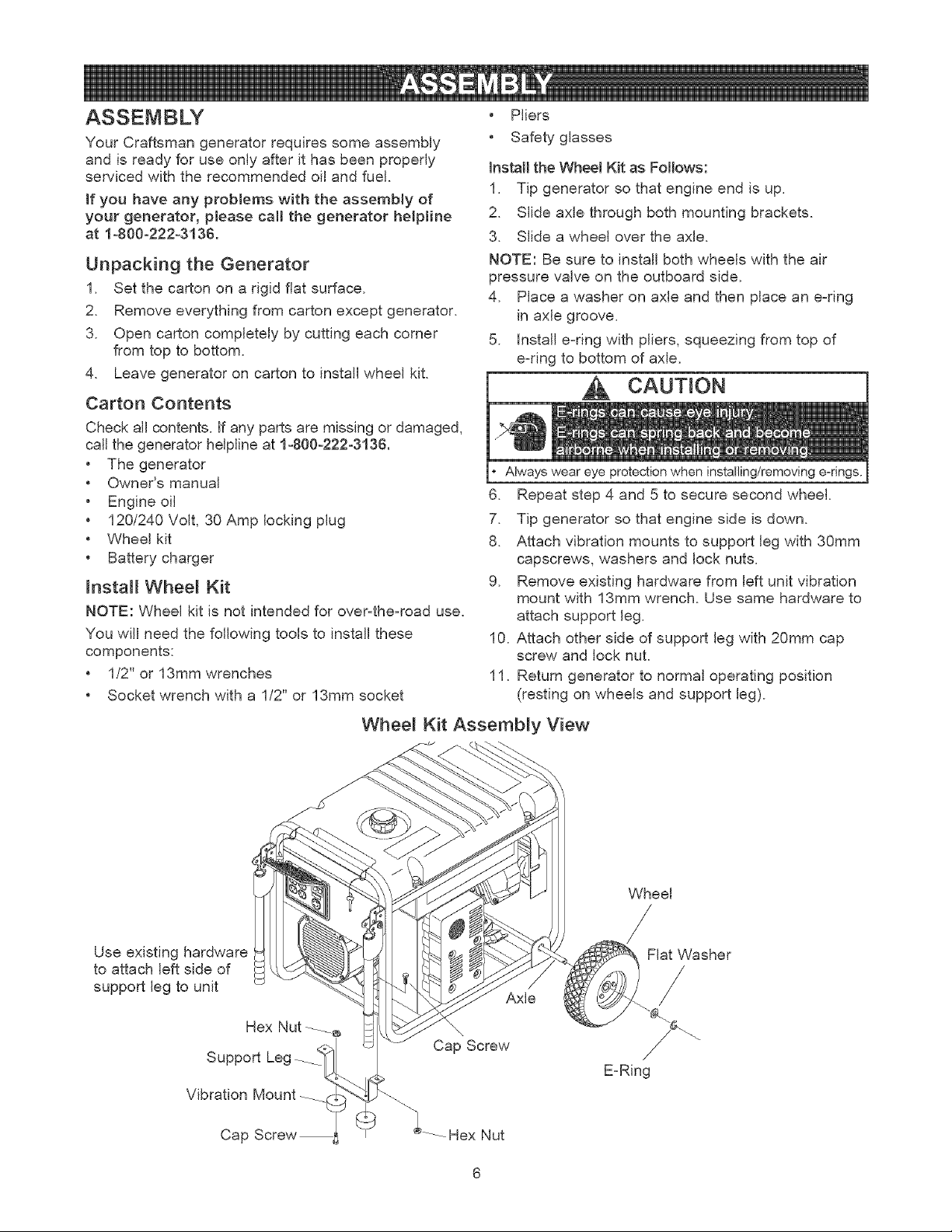
Install Wheel Kit
NOTE: Wheel kit is not intended for over-the-road use.
You will need the following tools to install these
components:
• 1/2" or 13mm wrenches
• Socket wrench with a 1/2" or 13mm socket
• Pliers
• Safety glasses
Install the Wheel Kit as Follows:
1. Tip generator so that engine end is up.
2. Slide axle through both mounting brackets.
3. Slide a wheel over the axle.
NOTE: Be sure to install both wheels with the air
pressure valve on the outboard side.
4. Place a washer on axle and then place an e-ring
in axle groove.
5. Install e-ring with pliers, squeezing from top of
e-ring to bottom of axle.
CAUTION
Always wear eye when
6. Repeat step 4 and 5 to secure second wheel.
7. Tip generator so that engine side is down.
8. Attach vibration mounts to support leg with 30mm
capscrews, washers and lock nuts.
9. Remove existing hardware from left unit vibration
mount with 13mm wrench. Use same hardware to
attach support leg.
10. Attach other side of support leg with 20mm cap
screw and lock nut.
11. Return generator to normal operating position
(resting on wheels and support leg).
Whee_ Kit Assembly View
Wheel
Use existing hardware
to attach left side of
support leg to unit
Hex Nut _e
Support Leg
Vibration Mount
Axle
\
Cap Screw
Flat Washer
/
E-Ring
Cap
Hex Nut
12.Checkthatallfastenersaretightandtiresareinflated
tovaluemarkedontireorwithin15and40psi.
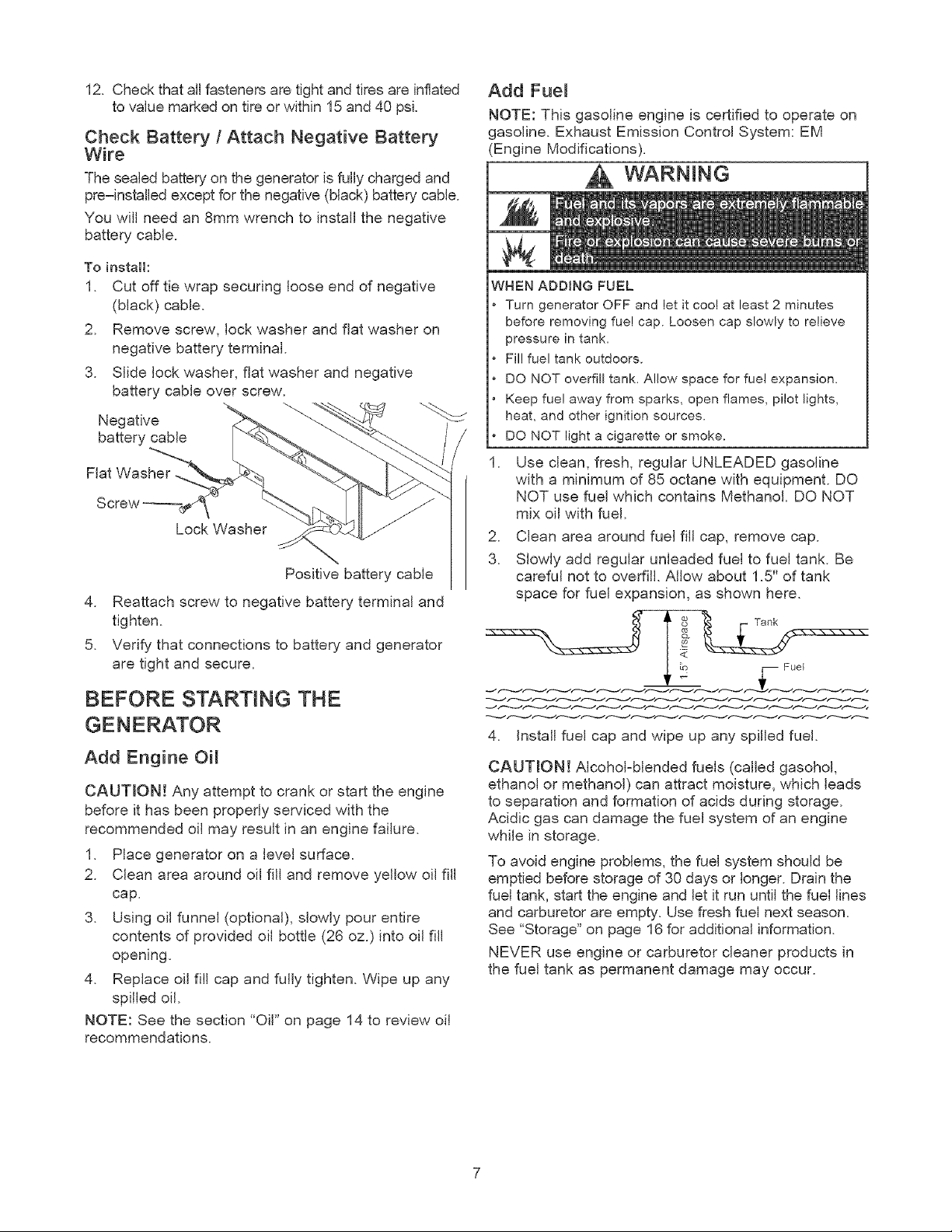
Check Battery / Attach Negative Battery
Wire
The sealed battery on the generator is fully charged and
pre-installed except for the negative (black) battery cable.
You will need an 8mm wrench to install the negative
battery cable.
To instalk
1. Cut off tie wrap securing loose end of negative
(black) cable.
2. Remove screw, lock washer and flat washer on
negative battery terminal.
3. Slide lock washer, flat washer and negative
battery cable over screw.
Negative
battery cable
Flat Washer,
Lock Washer
Positive battery cable
4. Reattach screw to negative battery terminal and
tighten.
5. Verify that connections to battery and generator
are tight and secure.
BEFORE STARTING THE
Add Engine Oi_
CAUTmON! Any attempt to crank or start the engine
before it has been properly serviced with the
recommended oil may result in an engine failure.
1. Place generator on a level surface.
2. Clean area around oil fill and remove yellow oil fill
cap.
3. Using oil funnel (optional), slowly pour entire
contents of provided oil bottle (26 oz.) into oil fill
opening.
4. Replace oil fill cap and fully tighten. Wipe up any
spilled oil.
NOTE: See the section "Oil" on page 14 to review oil
recommendations.
Add Fuem
NOTE: This gasoline engine is certified to operate on
gasoline. Exhaust Emission Control System: EM
(Engine Modifications).
WARNING
WHEN ADDING FUEL
Turn generator OFF and let it coo! at least 2 minutes
before removing fue! cap. Loosen cap slowly to relieve
pressure in tank.
Fil!fuel tank outdoors.
DO NOT overfill tank. Allow space for fuel expansion.
Keep fue! away from sparks, open flames, pilot lights,
heat, and other ignition sources.
DO NOT light a cigarette or smoke.
1. Use clean, fresh, regular UNLEADED gasoline
with a minimum of 85 octane with equipment. DO
NOT use fuel which contains Methanol. DO NOT
mix oil with fuel.
2. Clean area around fuel fill cap, remove cap.
3. Slowly add regular unleaded fuel to fuel tank. Be
careful not to overfill. Allow about 1.5" of tank
space for fuel expansion, as shown here.
4. Install fuel cap and wipe up any spilled fuel.
CAUTRON! Alcohol-blended fuels (called gasohol,
ethanol or methanol) can attract moisture, which leads
to separation and formation of acids during storage.
Acidic gas can damage the fuel system of an engine
while in storage.
To avoid engine problems, the fuel system should be
emptied before storage of 30 days or longer. Drain the
fuel tank, start the engine and let it run until the fuel lines
and carburetor are empty. Use fresh fuel next season.
See "Storage" on page 16 for additional information.
NEVER use engine or carburetor cleaner products in
the fuel tank as permanent damage may occur.
HOW TO USE YOUR GENERATOR
if you have any problems operating your generator,
please call the generator helpline at 1=800-222-3136.
System Ground
The generator has a system ground that connects the
generator frame components to the ground terminals
on the AC output receptacles. The system ground is
connected to the AC neutral wire (the neutral is
bonded to the generator flame).
Special Requirements
There may be Federal or State Occupational Safety
and Health Administration (OSHA) regulations, local
codes, or ordinances that apply to the intended use of
the generator. Please consult a qualified electrician,
electrical inspector, or the local agency having
jurisdiction.
• in some areas, generators are required to be
registered with local utility companies.
• if the generator is used at a construction site, there
may be additional regulations which must be
observed.
Connecting to a BuHding's E_ectrica_
System
Connections for standby power to a building's
electrical system must be made by a qualified
electrician. The connection must isolate the generator
power from utility power, and must comply with all
applicable laws and electrical codes.
WARNING
When using generator for backup power, notify utility
company. Use approved transfer equipment to isolate
generator from electric utility.
Use a ground circuit fault interrupter (GFCI) in any damp
or highly conductive area, such as metal decking or steel
work.
DO NOT touch bare wires or receptacles.
DO NOT use generator with electrical cords which are
worn, frayed, bare or otherwise damaged.
DO NOT operate generator in the rain or wet weather.
DO NOT handle generator or electrical cords while
standing in water, while barefoot, or while hands or feet
are wet,
DO NOT allow unqualified persons or children to operate
or service generator.
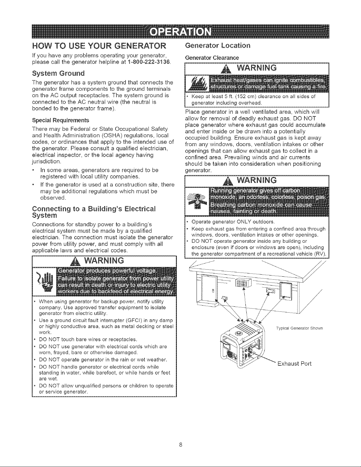
Generator Location
Generator Clearance
WARNING
Keep at least 5 ft. (152 cm) clearance on all sides of
generator including overhead.
Place generator in a well ventilated area, which will
allow for removal of deadly exhaust gas. DO NOT
place generator where exhaust gas could accumulate
and enter inside or be drawn into a potentially
occupied building. Ensure exhaust gas is kept away
from any windows, doors, ventilation intakes or other
openings that can allow exhaust gas to collect in a
confined area. Prevailing winds and air currents
should be taken into consideration when positioning
generator.
WARNING
Operate generator ONLY outdoors.
Keep exhaust gas from entering a confined area through
windows, doors, ventilation intakes or other openings.
DO NOT operate generator inside any building or
enclosure (even if doors or windows are open), including
the generator compartment of a recreational vehicle (RV).
Typical Generator Shown
Exhaust Port
TO START THE ENGINE
IMPORTANT: AM_ays unplug the battery float charger
before starting the generator.
Disconnect all electrical loads from the generator. Use
the following start instruction steps by numerical order:
1. Make sure unit is on a level surface.
IMPORTANT: Failure to start and operate unit on a
level surface will cause the unit not to start or shut
down during operation.
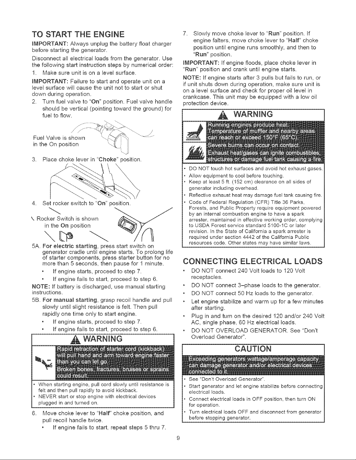
2. Turn fuel valve to "On" position. Fuel valve handle
should be vertical (pointing toward the ground) for
fuel to flow.
Fuel Valve is shown
in the On position
3. Place choke lever in "Choke" position.
4. Set rocker switch to "On" position.
\ Rocker Switch is shown
in the On position
5A. For electric starting, press start switch on
generator cradle until engine starts. To prolong life
of starter components, press starter button for no
more than 5 seconds, then pause for 1 minute.
• if engine starts, proceed to step 7.
• if engine fails to start, proceed to step 6.
NOTE: If battery is discharged, use manual starting
instructions.
5B. For manual starting, grasp recoil handle and pull
slowly until slight resistance is felt. Then pull
rapidly one time only to start engine.
• if engine starts, proceed to step 7.
• if engine fails to start, proceed to step 6.
m,wAR.I.G ]
.
When starting engine, pull cord slowly until resistance is
felt and then pull rapidly to avoid kickback.
NEVER start or stop engine with electrical devices
plugged in and turned on.
Move choke lever to "Half" choke position, and
pull recoil handle twice.
• If engine fails to start, repeat steps 5 thru 7.
7. Slowly move choke lever to "Run" position. If
engine falters, move choke lever to "Half" choke
position until engine runs smoothly, and then to
"Run" position.
IMPORTANT: If engine floods, place choke lever in
"Run" position and crank until engine starts.
NOTE: If engine starts after 3 pulls but fails to run, or
if unit shuts down during operation, make sure unit is
on a level surface and check for proper oil level in
crankcase. This unit may be equipped with a low oil
orotection device.
WARNING
DO NOT touch hot surfaces and avoid hot exhaust gases.
Allow equipment to coo! before touching.
Keep at least 5 ft. (152 cm) clearance on all sides of
generator including overhead.
Reflective exhaust heat may damage fue! tank causing fire.
Code of Federal Regulation (CFR) Title 36 Parks,
Forests, and Public Property require equipment powered
by an internal combustion engine to have a spark
arrester, maintained in effective working order, complying
to USDA Forest service standard 5100olC or later
revision. In the State of California a spark arrester is
required under section 4442 of the California Public
resources code. Other states may have similar laws.
CONNECTING ELECTRICAL LOADS
• DO NOT connect 240 Volt loads to 120 Volt
receptacles.
• DO NOT connect 3=phase loads to the generator.
• DO NOT connect 50 Hz loads to the generator.
• Let engine stabilize and warm up for a few minutes
after starting.
• Plug in and turn on the desired 120 and/or 240 Volt
AC, single phase, 60 Hz electrical loads.
• DO NOT OVERLOAD GENERATOR. See "Don't
Overload Generator".
CAUTION
See "Don't Overload Generator".
Start generator and let engine stabilize before connecting
electrical loads.
Connect electrical loads in OFF position, then turn ON
for operation.
Turn electrical loads OFF and disconnect from generator
before stopping generator.
TO STOP THE ENGINE
1. Unplug all electrical loads from generator panel
.
3.
receptacles. NEVER start or stop engine with
electrical devices plugged in and turned on.
Let engine run at no-load for several minutes to
stabilize internal temperatures of generator.
Move rocker switch to "Off" position.
CAUTION
• DO NOT stop engine by moving choke lever to 'Choke"
position.
4. Move fuel valve to "Off" position.
CORD SETS AND RECEPTACLES
Use only high quality, weGinsulated, extension cords
with the generator's 120 Volt electrical receptacles.
Check the ratings of all extension cords before you
use them. Extension cord sets used should be rated
for 125 Volt AC loads at 20 Amps or greater for most
electrical devices. Some devices, however, may not
require this type of extension cord. Check the owner's
manuals of those devices for the manufacturer's
recommendations.
Keep extension cords as short as possible, preferably
less than 15 feet long, to prevent voltage drop and
possible overheating of wires.
CAUTION
i
• NEVER attempt to power a device requiring more
amperage than generator or receptacle can supply,
• DO NOT overload the generator, See "Don't Overload
Generator",
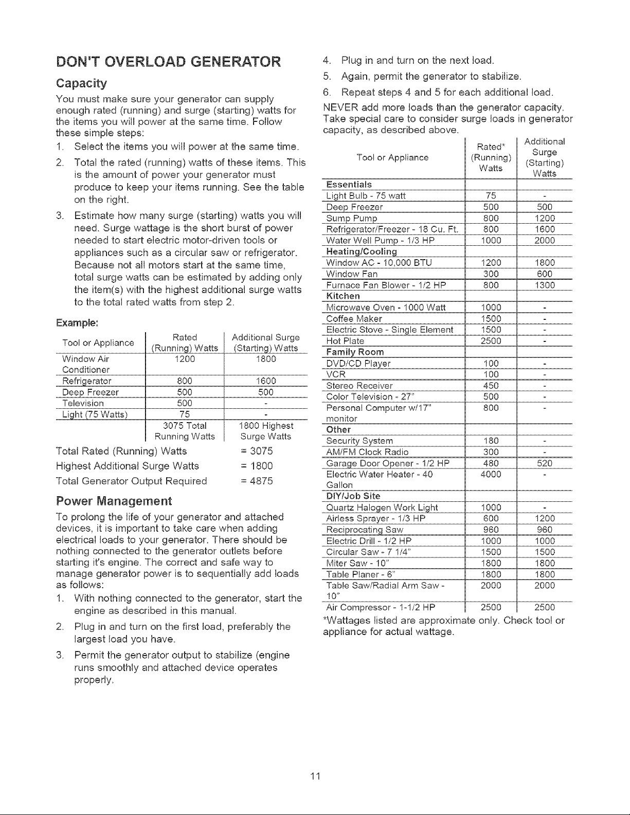
120 Volt AC, 20 Amp Dupmex Receptacle
Each receptacle is protected against overload by a
single 20 Amp push-to-reset circuit breaker. Use each
receptacle to operate 120 Volt AC, single phase 60 Hz
electrical loads requiring up to 2,400 watts (2.4 kW) at
20 Amps of current.
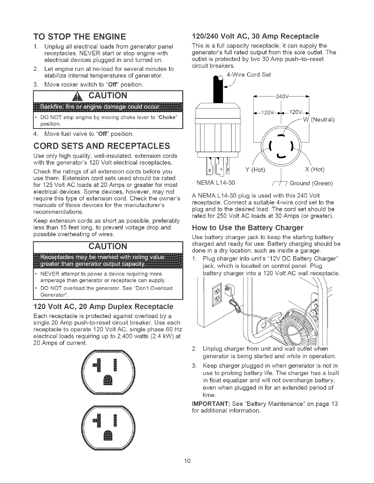
120/240 Volt AC, 30 Amp Receptacle
This is a full capacity receptacle; it can supply the
generator's full rated output from this sole outlet. The
outlet is protected by two 30 Amp push-to-reset
circuit breakers.
4-Wire Cord Set
/
1
NEMA L14-30
(Neutral)
Y (Hot) _ X (Hot)
Ground (Green)
A NEMA L14-30 plug is used with this 240 Volt
receptacle. Connect a suitable 4-wire cord set to the
plug and to the desired load. The cord set should be
rated for 250 Volt AC loads at 30 Amps (or greater).
How to Use the Battery Charger
Use battery charger jack to keep the starting battery
charged and ready for use. Battery charging should be
done in a dry location, such as inside a garage.
1. Plug charger into unit's "12V DC Battery Charger"
jack, which is located on control panel. Plug
battery charger into a 120 Volt AC wall rece )tacle.
y
2. Unplug charger from unit and wall outlet when
generator is being started and while in operation.
3. Keep charger plugged in when generator is not in
use to prolong battery life. The charger has a built
in float equalizer and will not overcharge battery,
even when plugged in for an extended period of
time.
IMPORTANT: See "Battery Maintenance" on page 13
for additional information.
10
DON'T OVERLOAD GENERATOR
Capacity
You must make sure your generator can supply
enough rated (running) and surge (starting) watts for
the items you will power at the same time. Follow
these simple steps:
1. Select the items you will power at the same time.
2. Total the rated (running) watts of these items. This
is the amount of power your generator must
produce to keep your items running. See the table
on the right.
3. Estimate how many surge (starting) watts you will
need. Surge wattage is the short burst of power
needed to start electric motor-driven tools or
appliances such as a circular saw or refrigerator.
Because not all motors start at the same time,
total surge watts can be estimated by adding only
the item(s) with the highest additional surge watts
to the total rated watts from step 2.
Example:
Tool or Appliance
Window Air
Conditioner
Refrigerator
Deep Freezer
Television
Li ht z75 Watts
Rated
(Running) Watts
1200
8OO
5OO
5OO
75
3075 Total
Running Watts
Total Rated (Running) Watts
Highest Additional Surge Watts
Total Generator Output Required
Power Management
Additional Surge
(Starting) Watts
1800
1600
500
1800 Highest
Surge Watts
= 3075
= 1800
= 4875
To prolong the life of your generator and attached
devices, it is important to take care when adding
electrical loads to your generator. There should be
nothing connected to the generator outlets before
starting it's engine. The correct and safe way to
manage generator power is to sequentially add loads
as follows:
1. With nothing connected to the generator, start the
engine as described in this manual.
2. Plug in and turn on the first load, preferably the
largest load you have.
3. Permit the generator output to stabilize (engine
runs smoothly and attached device operates
properly.
4. Plug in and turn on the next load.
5. Again, permit the generator to stabilize.
6. Repeat steps 4 and 5 for each additional load.
NEVER add more loads than the generator capacity.
Take special care to consider surge loads in generator
capacity, as described above.
Too! or Appliance
Essentials
Light Bulb - 75 watt
Deep Freezer
Sump Pump
Refrigerator/Freezer- 18 Cu. Ft.
Water Well Pump - 1/3 HP
Heating/Cooling
Window AC - 10,000 BTU
Window Fan
Furnace Fan Blower- 1/2 HP
Kitchen
Microwave Oven - 1000 Watt
Coffee Maker
Electric Stove - Single Element
Hot Plate
Family Room
DVD/CD Plaver
VCR
Stereo Receiver
Color Television - 27"
Personal Computer w/17"
monitor
Other
Security System
AM/FM Clock Radio
Garage Door Opener - 1/2 HP
Electric Water Heater - 40
Gallon
D_Y/Job Site
Quartz Haloqen Work Light
Airless Sprayer - 1/3 HP
Reci rocatin Saw
Electric Drill - 1/2 HP
Circular Saw - 7 1/4"
Miter Saw - 10"
Table Planer - 6"
Table Saw/Radial Arm Saw -
10"
Air Compressor - 1-1/2 HP
*Wattages listed are approximate only.
appliance for actual wattage.
Additional
Rated*
Surge
(Running) (Starting)
Watts
Watts
75
500 500
800 1200
800 1600
1000 2000
1200 1800
300 600
800 1300
1000
1500
1500
2500
100
100
45O
5OO
8OO
180
3OO
480 520
4000
1000
600 1200
960 960
1000 1000
1500 1500
1800 1800
1800 1800
2000 2000
2500 2500
Check tool or
11
ENGINE TECHNICAL INFORMATION
This is a single cylinder, overhead valve(OHV), air
cooled engine, it is a low emissions engine.
in the State of California, Model Series 210000
engines are certified by the California Air Resources
Board to meet emissions standards for 250 hours.
Such certification does not grant the purchaser, owner
or operator of this engine any additional warranties
with respect to the performance or operational life of
this engine. The engine is warranted solely according
to the product and emmisions warranties stated
elsewhere in this manual.
Power Ratings
The power ratings for an individual engine model are
initially developed by starting with SAE (Society of
Automotive Engineers) code J1940 (Small Engine
Power & Torque Rating Procedure) (Revision 2002-
05). Given both the wide array of products on which
our engines are placed, and the variety of
environmental issues applicable to operating the
equipement, it may be that the engine you have
purchased will not develop the rated horsepower when
used in a peice of power equipment (actual "on-site"
power). This difference is due to a variety of factors
including, but not limited to, the following: differences
in altitude, temperature, barometric pressure, humidity,
fuel, engine lubrication, maximum governed engine
speed, individual engine to engine variability, design of
the particular peice of power equipment, the manner in
which the engine is operated, engine run-in to reduce
friction and clean out of combustion chambers,
adjustments to the valves and carburetor, and other
factors. The power ratings may also be adjusted
based on comparisons to other similar engines
utilizedin similar applications, and will thereforenot
necessarily match the values derived using the
foregoing codes.
PRODUCT SPECIFICATIONS
Generator Specifications
Wattage .................... 6300 Watts (6.3 kW)
Starting Wattage ............. 9100 Watts (9.1 kW)
Rated AC Voltage ............ 120/240 Volts
Rated AC Current
at 240 Volts ............... 26.3 Amperes
at 120 Volts ............... 52.5 Amperes
Rated Frequency ............. 60 Hz at 3600 rpm
Phase ...................... Single Phase
Unit Weight ................. 198 Ibs,
Engine Specifications
Rated Horsepower ............ 11 at 3600 rpm
Bore ....................... 3,3 in. (83,81 mm)
Stroke ...................... 2,438 in. (61,67 mm)
Displacement ................ 20,85 in. (342 cc)
Spark Plug
Type: ................. Champion RC12YC or
Equivalent
Set Gap To: ............ 0,030inch (0.76mm)
Armature Air Gap: ............ 0,008-0,012 in.
(0 20-0,30ram)
Valve clearance with valve springs installedand piston 1/4 in.
(6 mm) past top dead center (check when engine is cold).
Intake ...................... 0,004-0,006 in.
(0.!0o0.!5 mm)
Exhaust .................... 0,004-0,006 in.
(0,!0-0,15 mm)
Fuel Capacity ................ 7 U.S. gallons
Oil Capacity ................. 28 fL oz,
Oil Type:
Above 40° F ............... SAE 30
Below 40° F ............... SAE 5W-30 or 10W-30
12
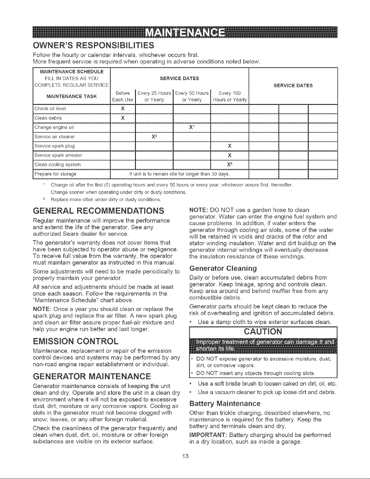
OWNER'S RESPONSIBILITIES
Follow the hourly or calendar intervals, whichever occurs first.
More frequent service is rec uired when operating in adverse conditions noted below.
MABNTENANCE SCHEDULE
FtLL tN DATES AS YOU
COMPLETE REGULAR SERVICE
MAINTENANCE TASK
Check oil level
Clean debris
Change engine oil
Service air cleaner
Service spark plug
Service spark arrester
Clean cooting system
Prepare for storage
SERVICE DATES
Before Every 25 Hours
Each Use or Yearly
X
x
X 2
Every 50 Hours
or Year y
X 1
Every 100
Hours or Yearly
x
x
x 2
If unit is to remain idle for longer than 30 days.
SERVICE DATES
Change oil after the first (5) operating hours and every 50 hours or every year, whichever occurs first, thereafter.
Change sooner when operating under dirty or dusty conditions.
Replace more often under dirty or dusty conditions.
GENERAL RECOMMENDATIONS
Regular maintenance will improve the performance
and extend the life of the generator. See any
authorized Sears dealer for service.
The generator's warranty does not cover items that
have been subjected to operator abuse or negligence.
To receive full value from the warranty, the operator
must maintain generator as instructed in this manual.
Some adjustments will need to be made periodically to
properly maintain your generator.
All service and adjustments should be made at least
once each season. Follow the requirements in the
"Maintenance Schedule" chart above.
NOTE: Once a year you should clean or replace the
spark plug and replace the air filter. A new spark plug
and clean air filter assure proper fuel-air mixture and
help your engine run better and last longer.
EMISSION CONTROL
Maintenance, replacement or repair of the emission
control devices and systems may be performed by any
non-road engine repair establishment or individual.
GENERATOR MAINTENANCE
Generator maintenance consists of keeping the unit
clean and dry. Operate and store the unit in a clean dry
environment where it will not be exposed to excessive
dust, dirt, moisture or any corrosive vapors. Cooling air
slots in the generator must not become clogged with
snow, leaves, or any other foreign material.
Check the cleanliness of the generator frequently and
clean when dust, dirt, oil, moisture or other foreign
substances are visible on its exterior surface.
NOTE: DO NOT use a garden hose to clean
generator. Water can enter the engine fuel system and
cause problems. In addition, if water enters the
generator through cooling air slots, some of the water
will be retained in voids and cracks of the rotor and
stator winding insulation. Water and dirt buildup on the
generator internal windings will eventually decrease
the insulation resistance of these windings.
Generator Cleaning
Daily or before use, clean accumulated debris from
generator. Keep linkage, spring and controls clean.
Keep area around and behind muffler free from any
combustible debris.
Generator parts should be kept clean to reduce the
risk of overheating and ignition of accumulated debris.
• Use a damp cloth to wipe exterior surfaces clean.
CAUTION
DO NOT expose generator to excessive moisture, dust,
dirt, or corrosive vapors,
DO NOT insert any objects through cooling slots,
• Use a soft bristle brush to loosen caked on dirt, oil, etc.
• Use a vacuum cleaner to pick up loose dirt and debris.
Battery Maintenance
Other than trickle charging, described elsewhere, no
maintenance is required for the battery. Keep the
battery and terminals clean and dry.
IMPORTANT: Battery charging should be performed
in a dry location, such as inside a garage.
13
ENGINE MAINTENANCE
WARNING
WHEN ADJUSTING OR MAKING REPAIRS TO YOUR
GENERATOR
Disconnect the spark plug wire from the spark plug and
place the wire where it cannot contact spark plug.
WHEN TESTING FOR ENGINE SPARK
Use approved spark plug tester.
DO NOT check for spark with spark plug removed,
Oil Recommendations
NOTE: When adding oil to the engine crankcase, use
only high quality detergent oil rated with API service
classification SF, SG, SH, SJ or higher. DO NOT use
special additives.
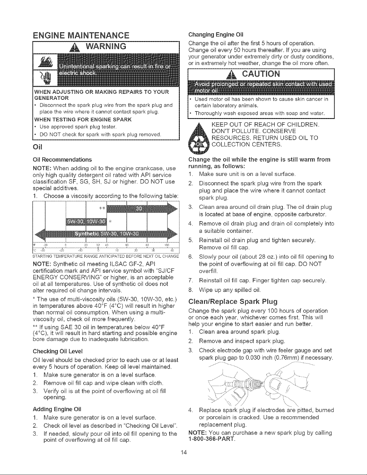
1. Choose a viscosity according to the following table:
J
100
C 30 2Q 10 0 10 20 30 40
STARTING TEMPERATURE RANGE ANTICIPATED BEFORE NEXT O_L CHANGE
NOTE: Synthetic oil meeting ILSAC GF-2, API
certification mark and API service symbol with "SJ/CF
ENERGY CONSERVING" or higher, is an acceptable
oil at all temperatures. Use of synthetic oil does not
alter required oil change intervals.
* The use of multi-viscosity oils (5W-30, 10W-30, etc.)
in temperatures above 40°F (4°C) will result in higher
than normal oil consumption. When using a multi-
viscosity oil, check oil more frequently.
** If using SAE 30 oil in temperatures below 40°F
(4°C), it will result in hard starting and possible engine
bore damage due to inadequate lubrication.
Checking Oil Levet
Oil level should be checked prior to each use or at least
every 5 hours of operation. Keep oil level maintained.
1. Make sure generator is on a level surface.
2. Remove oil fill cap and wipe clean with cloth.
3. Verify{ oil is at the point of overflowing at oil fill
opening.
Adding Engine Oim
1. Make sure generator is on a level surface.
2. Check oil level as described in "Checking Oil Level".
3. If needed, slowly pour oil into oil fill opening to the
point of overflowing at oil fill cap.
Changing Engine OH
Change the oil after the first 5 hours of operation.
Change oil every 50 hours thereafter. If you are using
your generator under extremely dirty or dusty conditions,
or in extremely hot weather, change the oil more often.
CAUTION
Used motor oil has been shown to cause skin cancer in
certain laboratory animals.
Thoroughly wash exposed areas with soap and water.
KEEP OUT OF REACH OF CHILDREN.
DON'T POLLUTE. CONSERVE
RESOURCES. RETURN USED OIL TO
COLLECTION CENTERS.
Change the oil while the engine is still warm from
running, as foitows:
1. Make sure unit is on a level surface.
2. Disconnect the spark plug wire from the spark
plug and place the wire where it cannot contact
spark plug.
3. Clean area around oil drain plug. The oil drain plug
is located at base of engine, opposite carburetor.
4. Remove oil drain plug and drain oil completely into
a suitable container.
5. Reinstall oil drain plug and tighten securely.
Remove oil fill cap.
6. Slowly pour oil (about 28 oz.) into oil fill opening to
the point of overflowing at oil fill cap. DO NOT
overfill.
7. Reinstall oil fill cap. Finger tighten cap securely.
8. Wipe up any spilled oil.
CJeantRep_ace Spark P_ug
Change the spark plug every 100 hours of operation
or once each year, whichever comes first. This will
help your engine to start easier and run better.
1. Clean area around spark plug.
2. Remove and inspect spark plug.
3. Check electrode gap with wire feeler gauge and set
spark plug gap to 0.030 inch (0.76mm) if necessary.
4. Replace spark plug if electrodes are pitted, burned
or porcelain is cracked. Use a recommended
replacement plug.
NOTE: You can purchase a new spark plug by calling
1-800-366-PART.
14
Service Air Cleaner
Your engine will not run properly and may be
damaged if you run it using a dirty air cleaner. Clean
or replace the air cleaner paper filter once every
25 hours of operation or once a year, whichever
comes first. Clean or replace more often if operating
under dusty or dirty conditions.
Service Air Filter
1. Loosen screws and remove air cleaner cover.
Remove paper filter.
Cartridge
Cover X_
Base
2. Install clean (or new) air cleaner assembly inside
cover. Dispose of old filter properly.
3. Assemble air cleaner cover onto base and tighten
screws.
NOTE: You can purchase new air cleaner elements by
calling 1-800-366-PART.
Cmean Spark Attester Screen
The engine exhaust muffler has a spark arrester
screen. Inspect and clean the screen every 100 hours
of operation or once each year, whichever comes first.
NOTE: You can purchase a new spark arrester screen
by calling 1-800-366-PART.
WARNING
if you use your generator on any forest-covered, brush-
covered, or grass-covered unimproved land, it must
have a spark arrester. The spark arrester must be
maintained in good condition by the owner/operator.
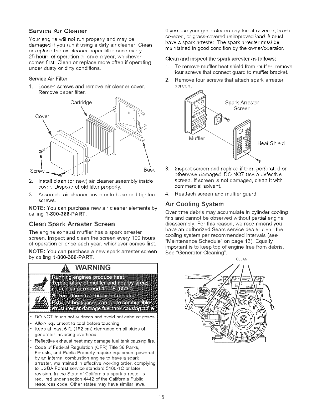
Clean and inspect the spark attester as follows:
1. To remove muffler heat shield from muffler, remove
four screws that connect guard to muffler bracket.
2. Remove four screws that attach spark arrester
screen.
Mumlr_NSpark Arrester
Screen .
eat Shield
3. inspect screen and replace if torn, perforated or
otherwise damaged. DO NOT use a defective
screen. If screen is not damaged, clean it with
commercial solvent.
4. Reattach screen and muffler guard.
Air Coo_ing System
Over time debris may accumulate in cylinder cooling
fins and cannot be observed without partial engine
disassembly. For this reason, we recommend you
have an authorized Sears service dealer clean the
cooling system per recommended intervals (see
"Maintenance Schedule" on page 13). Equally
important is to keep top of engine free from debris.
See "Generator Cleaning".
CLEAN
DO NOT touch hot surfaces and avoid hot exhaust gases.
Allow equipment to cool before touching.
Keep at least 5 ft. (152 cm) clearance on all sides of
generator including overhead.
Reflective exhaust heat may damage fuel tank causing fire.
Code of Federal Regulation (CFR) Title 36 Parks,
Forests, and Public Property require equipment powered
by an internal combustion engine to have a spark
arrester, maintained in effective working order, complying
to USDA Forest service standard 5100-1C or later
revision. In the State of California a spark arrester is
required under section 4442 of the California Public
resources code. Other states may have similar laws.
15
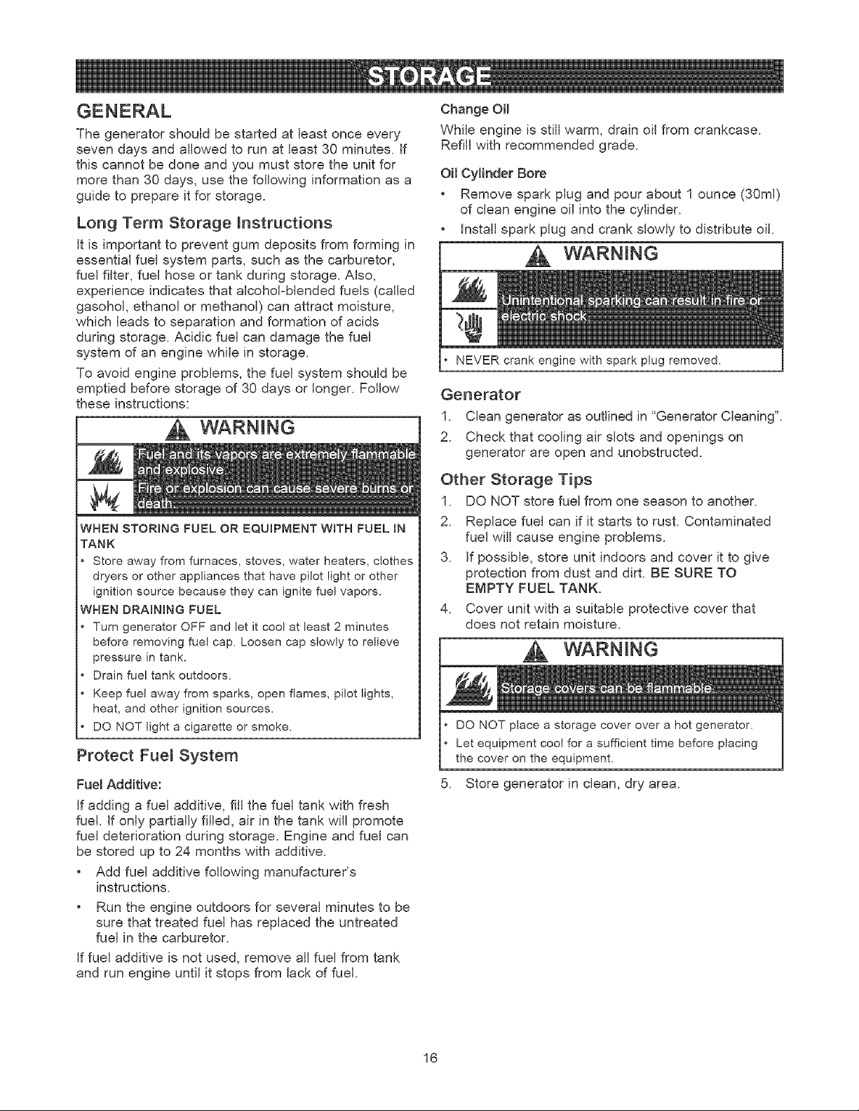
Thegeneratorshouldbestartedatleastonceevery
sevendaysandallowedtorunat least30minutes.If
thiscannotbedoneandyoumuststoretheunitfor
morethan30days,usethefollowinginformationasa
guideto prepareitforstorage.
Long Term Storage _nstructions
it is important to prevent gum deposits from forming in
essential fuel system parts, such as the carburetor,
fuel filter, fuel hose or tank during storage. Also,
experience indicates that alcohol-blended fuels (called
gasohol, ethanol or methanol) can attract moisture,
which leads to separation and formation of acids
during storage. Acidic fuel can damage the fuel
system of an engine while in storage.
To avoid engine problems, the fuel system should be
emptied before storage of 30 days or longer. Follow
these instructions:
WARNING
WHEN STORING FUEL OR EQUIPMENT WITH FUEL IN
TANK
Store away from furnaces, stoves, water heaters, clothes
dryers or other appliances that have pilot light or other
ignition source because they can ignite fuel vapors.
WHEN DRAiNiNG FUEL
Turn generator OFF and let it cool at least 2 minutes
before removing fuel cap. Loosen cap slowly to relieve
pressure in tank.
Drain fuel tank outdoors.
Keep fuel away from sparks, open flames, pilot lights,
heat, and other ignition sources,
DO NOT light a cigarette or smoke.
Protect Fue_ System
Fuel Additive:
If adding a fuel additive, fill the fuel tank with fresh
fuel. If only partially filled, air in the tank will promote
fuel deterioration during storage. Engine and fuel can
be stored up to 24 months with additive.
• Add fuel additive following manufacturer's
instructions.
• Run the engine outdoors for several minutes to be
sure that treated fuel has replaced the untreated
fuel in the carburetor.
If fuel additive is not used, remove all fuel from tank
and run engine until it stops from lack of fuel.
Change OH
While engine is still warm, drain oil from crankcase.
Refill with recommended grade.
OHCylinder Sore
• Remove spark plug and pour about 1 ounce (30ml)
of clean engine oil into the cylinder.
• Install spark plug and crank slowly to distribute oil.
WARNING
NEVER crank enqine with spark plug removed,
Generator
1. Clean generator as outlined in "Generator Cleaning".
2. Check that cooling air slots and openings on
generator are open and unobstructed.
Other Storage Tips
1. DO NOT store fuel from one season to another.
2. Replace fuel can if it starts to rust. Contaminated
fuel will cause engine problems.
3. If possible, store unit indoors and cover it to give
protection from dust and dirt. BE SURE TO
EMPTY FUEL TANK.
4. Cover unit with a suitable protective cover that
does not retain moisture.
.
DO NOT place a storage cover over a hot generator.
Let equipment cool for a sufficient time before placing
the cover on the equipment.
Store generator in clean, dry area.
16
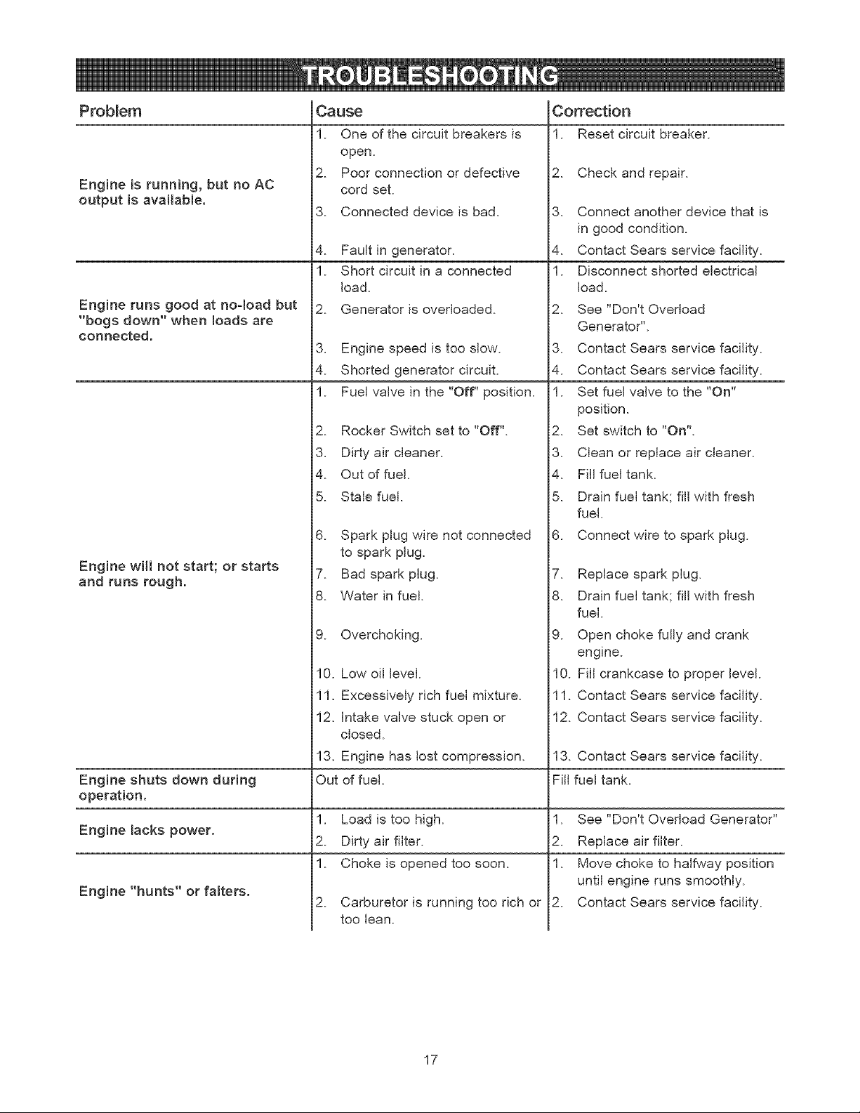
Prob{em
Engine Bsrunning, but no AC
output is available.
EngBne runs good at no-load but
"bogs down" when loads are
connected.
C_use
One of the circuit breakers is
open.
Poor connection or defective
cord set.
3. Connected device is bad.
.
Fault in generator.
Short circuit in a connected
load.
Generator is overloaded.
3. Engine speed is too slow.
4. Shorted generator circuit.
Fuel valve in the "Off" position.
Rocker Switch set to "Off".
3. Dirty air cleaner.
4. Out of fuel.
5. Stale fuel.
Correction
Reset circuit breaker.
Check and repair.
3. Connect another device that is
in good condition.
4. Contact Sears service facility.
Disconnect shorted electrical
load.
See "Don't Overload
Generator".
3. Contact Sears service facility.
4. Contact Sears service facility.
Set fuel valve to the "On"
position.
Set switch to "On".
6. Spark plug wire not connected
Engine will not start; or stars
and runs rough.
3. Clean or replace air cleaner.
4. Fill fuel tank.
5. Drain fuel tank; fill with fresh
fuel.
6. Connect wire to spark plug.
to spark plug.
7. Bad spark plug.
8. Water in fuel.
9. Overchoking.
7. Replace spark plug.
8. Drain fuel tank; fill with fresh
fuel.
9. Open choke fully and crank
engine.
10. Low oil level.
11. Excessively rich fuel mixture.
12. Intake valve stuck open or
closed.
13. Engine has lost compression.
Engine shuts down during Fill
operation.
Load is too high.
Engine lacks power.
Dirty air filter.
Choke is opened too soon.
Engine "hunts" or ratters.
Carburetor is running too rich or
too lean.
0. Fill crankcase to proper level.
1. Contact Sears service facility.
2. Contact Sears service facility.
3. Contact Sears service facility.
fuel tank.
See "Don't Overload Generator"
Replace air filter.
Move choke to halfway position
until engine runs smoothly.
Contact Sears service facility.
17
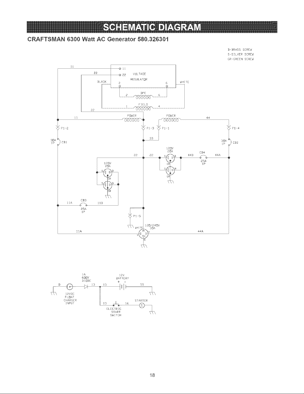
CRAFTSMAN B300 Watt AC Generator 580.326301
11
22
B-SRAS$ SCREW
S-SILVER SCREW
GR OREEN SCREW
IP
22
POWER
PI 2
CSl
S B
GR
EB3
25A
IP
11A
22
120/248V
30A
POWER
120V
20A
44
30A
I P
CB4
44B _-_o 44A
25A
1P
44A
CB2
\32
_IOAT
CHAR@!!KR
INPUT
IA
600V
DIODE
12V
BATTERY
+ i
iiI ss
STARTER
_s l _6
ELECTRIC
START
SW]TCH
18
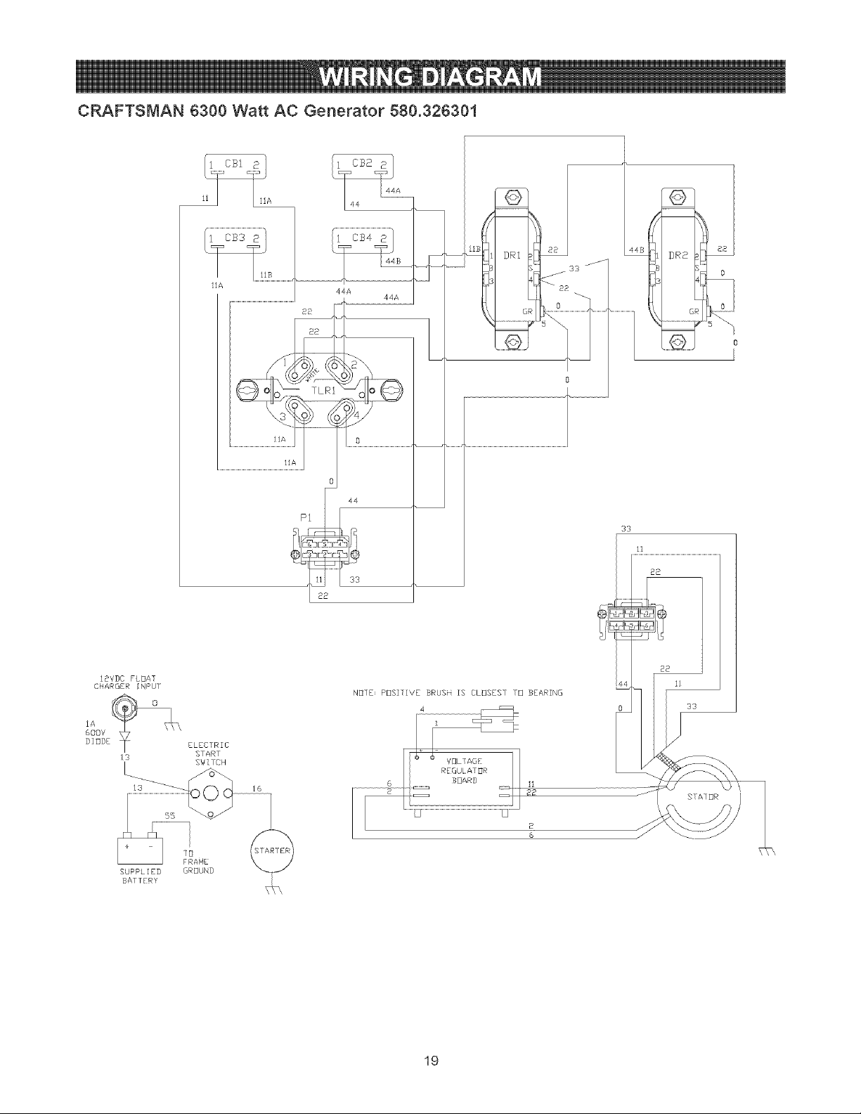
CRAFTSMAN 6300 Watt AC Generator 580.326301
IBVDC FLOAT
CHARGER [NPUr
SUPPLIED
BATTERY
22
]_A 8
0
44
pi
33
33
ELECTRIC
START
SWITCH
NEITE: PBSITIVE BRUSH IS CLUSEST TO BEARING
_2
GROUND
11
22
STATOR
19
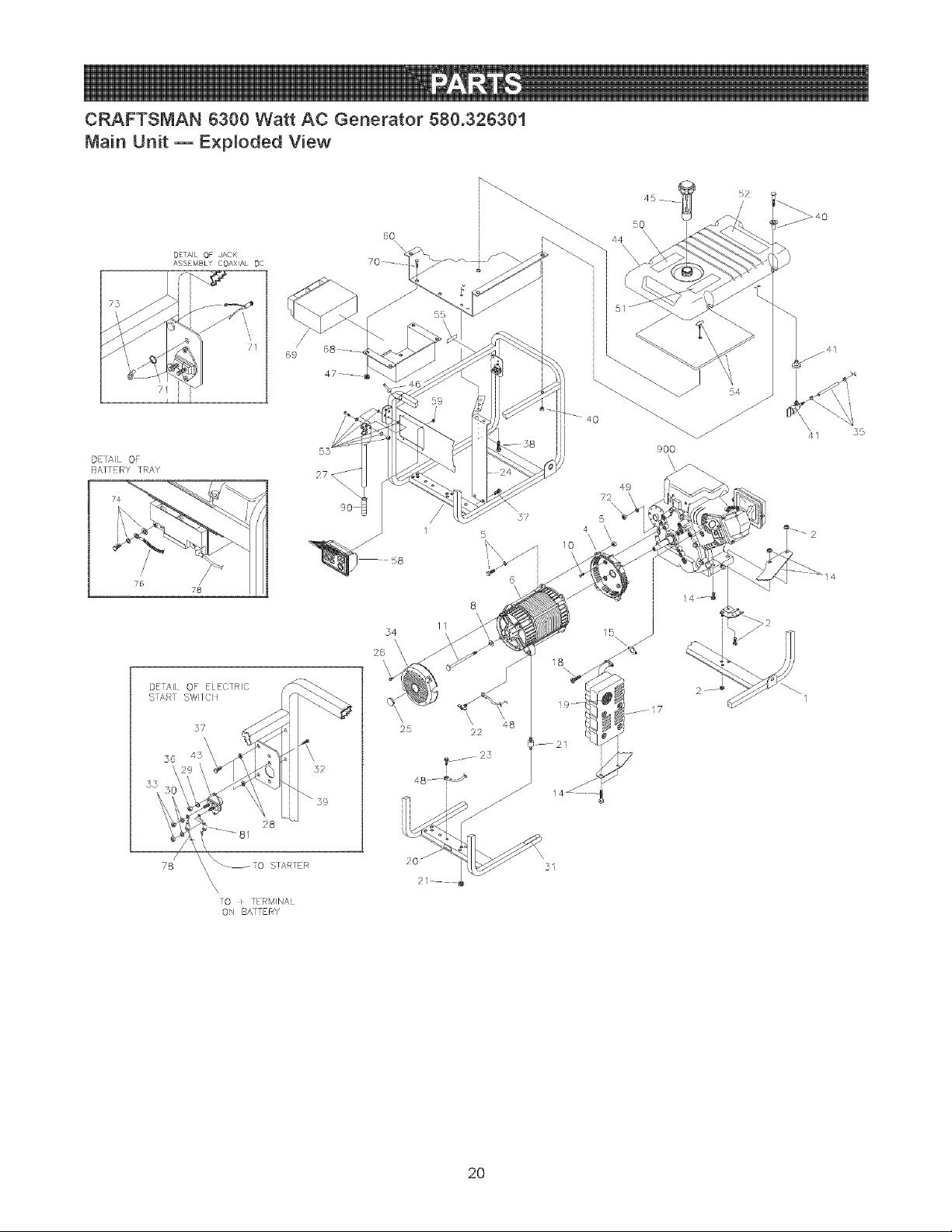
CRAFTSMAN 6300 Watt AC Generator 580.326301
Main Unit m E×p_oded View
DETAIL OF JACK
ASSEMBLY COAXAL 9C
71 i i
i i i
DEIAiL OF
BATTERY TRAY
75
78
DETAIl OF ELECTRIC
S;AR SWI/CI!
37
\
}6 45
52
_39
78 STARTER
\
\
\
[0 t IERMINAI
ON BAiTERY
9O
5q
\
26
55
X
6
8
\
//
\
\ \
\
25 22
52
/
50
44
9OO
\\
5
4
\
\
72
49
41
2O
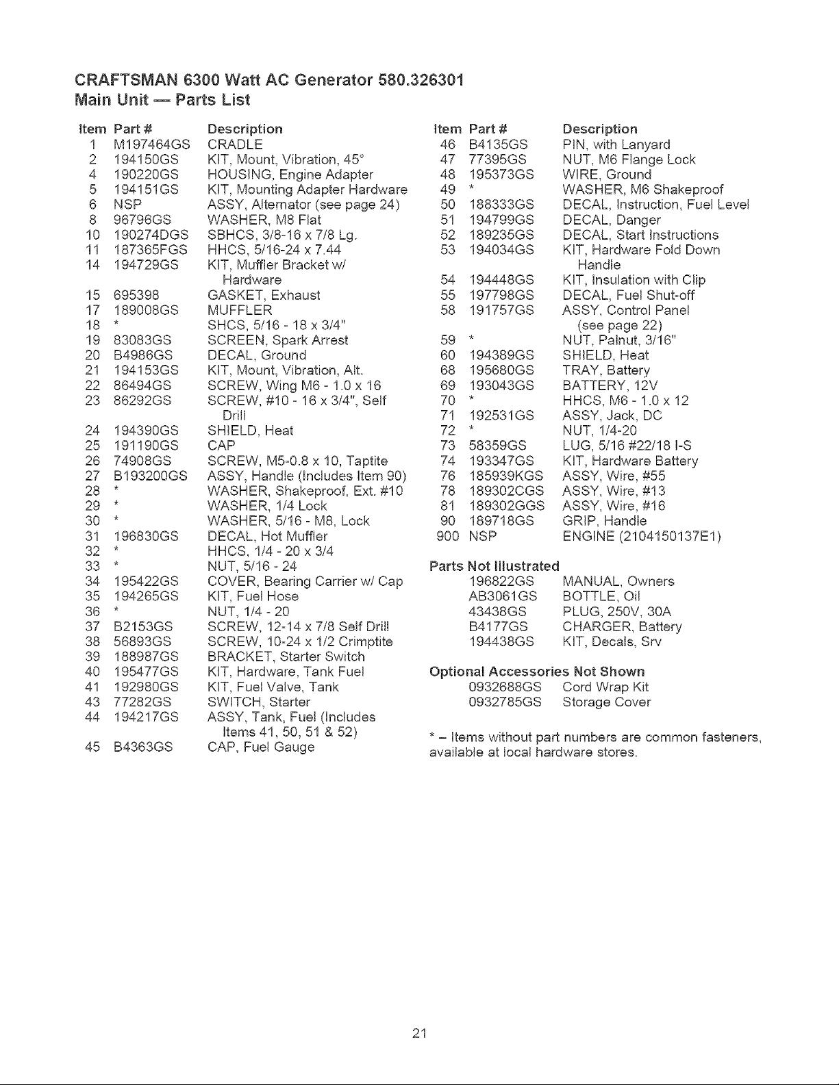
CRAFTSMAN 6300 Watt AC Generator 580.326301
Main Unit m Parts List
Item Part #
1 M197464GS
2 194150GS
4 190220GS
5 194151GS
6 NSP
8 96796GS
10 190274DGS
11 187365FGS
14 194729GS
15 695398
17 189008GS
18 *
19 83083GS
20 B4986GS
21 194153GS
22 86494GS
23 86292GS
24 194390GS
25 191190GS
26 74908GS
27 B193200GS
28 *
29 *
30 *
31 196830GS
32 *
33 *
34 195422GS
35 194265GS
36 *
37 B2153GS
38 56893GS
39 188987GS
40 195477GS
41 192980GS
43 77282GS
44 194217GS
45 B4363GS
Description Item
CRADLE 46
KIT, Mount, Vibration, 45 ° 47
HOUSING, Engine Adapter 48
KIT, Mounting Adapter Hardware 49
ASSY, Alternator (see page 24) 50
WASHER, M8 Flat 51
SBHCS, 3/8-16 x 7/8 Lg. 52
HHCS, 5/16-24 x 7.44 53
KIT, Muffler Bracket w/
Hardware 54
GASKET, Exhaust 55
MUFFLER 58
SHCS, 5/16 - 18 x 3/4"
SCREEN, Spark Arrest 59
DECAL, Ground 60
KIT, Mount, Vibration, AIt. 68
SCREW, Wing M6 - 1.0 x 16 69
SCREW, #10 - 16 x 3/4", Self 70
Drill 71
SHIELD, Heat 72
CAP 73
SCREW, M5-0.8 x 10, Taptite 74
ASSY, Handle (Includes item 90) 76
WASHER, Shakeproof, Ext. #10 78
WASHER, 1/4 Lock 81
WASHER, 5/16 - M8, Lock 90
DECAL, Hot Muffler 900
HHCS, 1/4 - 20 x 3/4
NUT, 5/16 - 24
COVER, Bearing Carrier w/Cap
KIT, Fuel Hose
NUT, 1/4 - 20
SCREW, 12-14 x 7/8 Self Drill
SCREW, 10-24 x 1/2 Cdmptite
BRACKET, Starter Switch
KIT, Hardware, Tank Fuel
KIT, Fuel Valve, Tank
SWITCH, Starter
ASSY, Tank, Fuel (Includes
Items 41,50, 51 & 52)
CAP, Fuel Gauge
Part #
B4135GS
77395GS
195373GS
188333GS
194799GS
189235GS
194034GS
194448GS
197798GS
191757GS
194389GS
195680GS
193043GS
192531GS
58359GS
193347GS
185939KGS
189302CGS
189302GGS
189718GS
NSP
Description
PIN, with Lanyard
NUT, M6 Flange Lock
WIRE, Ground
WASHER, M6 Shakeproof
DECAL, Instruction, Fuel Level
DECAL, Danger
DECAL, Start Instructions
KIT, Hardware Fold Down
Handle
KIT, Insulation with Clip
DECAL, Fuel Shut-off
ASSY, Control Panel
(see page 22)
NUT, Palnut, %16"
SHIELD, Heat
TRAY, Battery
BATTERY, 12V
HHCS, M6- 1.0 x 12
ASSY, Jack, DC
NUT, 1/4-20
LUG, 5/16 #22/18 I-S
KIT, Hardware Battery
ASSY, Wire, #55
ASSY, Wire, #13
ASSY, Wire, #16
GRIP, Handle
ENGINE (2104150137E1 )
Parts Not Htustrated
196822GS
AB3061GS
43438GS
B4177GS
194438GS
MANUAL, Owners
BOTTLE, Oil
PLUG, 250V, 30A
CHARGER, Battery
KIT, Decals, Srv
Optional Accessories Not Shown
0932688GS Cord Wrap Kit
0932785GS Storage Cover
* - Items without part numbers are common fasteners,
available at local hardware stores.
21
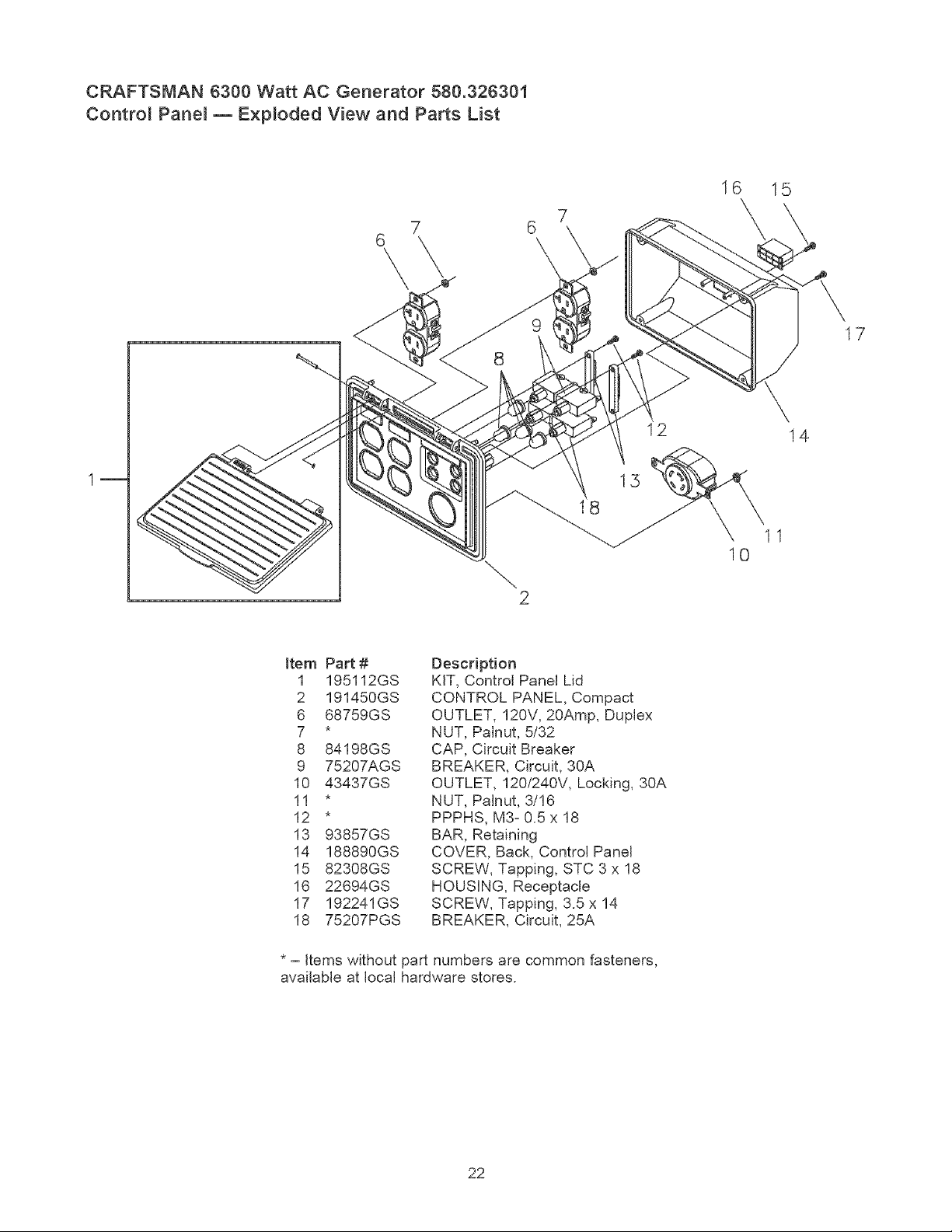
CRAFTSMAN 6300 Watt AC Generator 580.326301
Contro{ Pane{ m Exp{oded View and Parts List
6
\
7
16
15
8
12
15
11
10
17
14
Item Part #
1 195112GS
2 191450GS
6 68759GS
7 *
8 84198GS
9 75207AGS
10 43437GS
11 *
12 *
13 93857GS
14 188890GS
15 82308GS
16 22694GS
17 192241GS
18 75207PGS
Description
KIT, Control Panel Lid
CONTROL PANEL, Compact
OUTLET, 120V, 20Amp, Duplex
NUT, Palnut, 5/32
CAP, Circuit Breaker
BREAKER, Circuit, 30A
OUTLET, 120/240V, Locking, 30A
NUT, Palnut, 3/16
PPPHS, M3- 0.5 x 18
BAR, Retaining
COVER, Back, Control Panel
SCREW, Tapping, STC 3 x 18
HOUSING, Receptacle
SCREW, Tapping, 3.5 x 14
BREAKER, Circuit, 25A
* - items without part numbers are common fasteners,
available at local hardware stores.
22
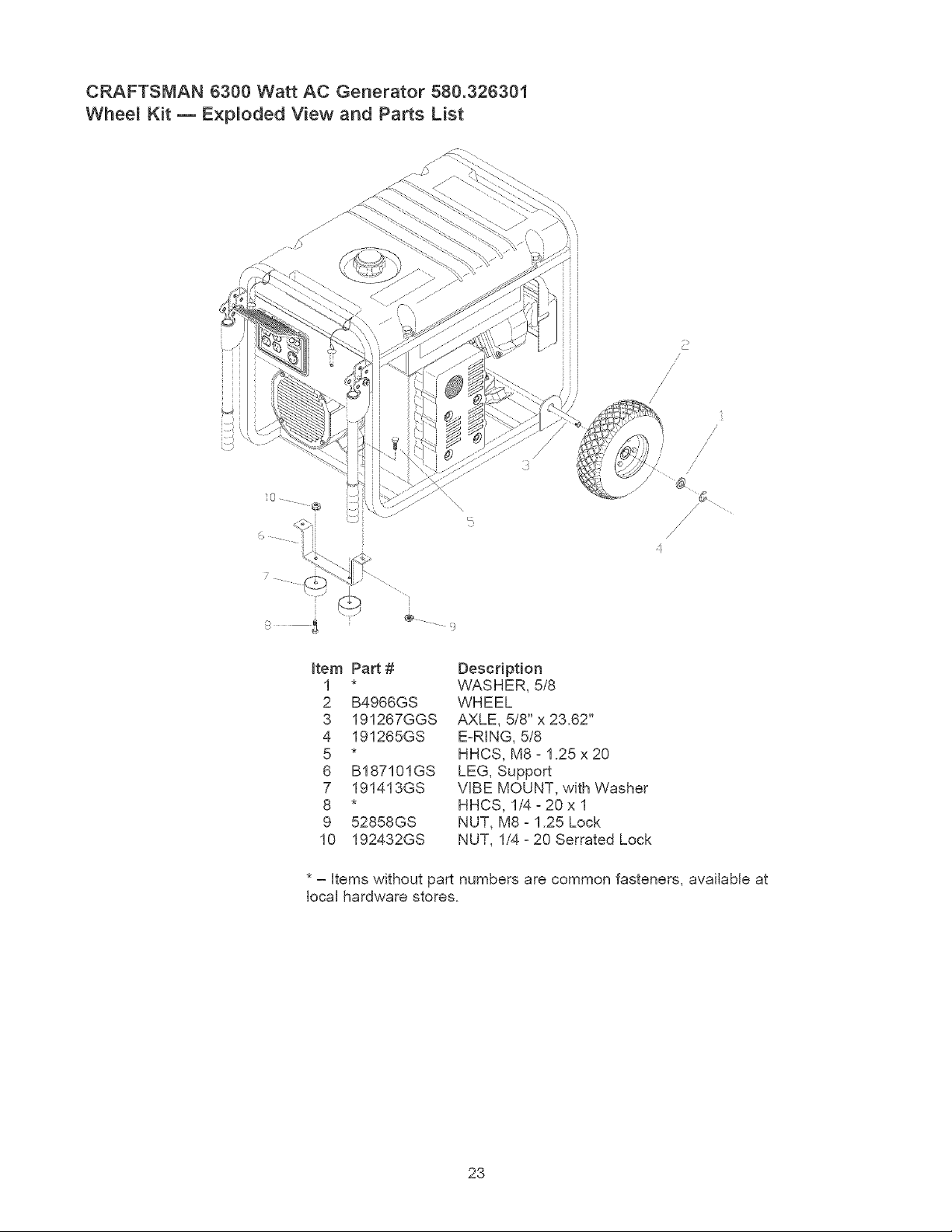
CRAFTSMAN 6300 Watt AC Generator 580.326301
Whee{ Kit m Exp{oded View and Parts List
_3
.... 9
/
/
/
/
/
/
/
/
/
/
Item Part # Description
1 * VVASHER, 5/8
2 B4966GS WHEEL
3 191267GGS AXLE, 5/8" x 23.62"
4 191265GS EzR]NG, 5/8
5 * HHCS, M8 z 1.25 x 20
6 B187101GS LEG, Support
7 191413GS VIBE MOUNT, with Washer
8 * HHCS, 1/4 _20 x 1
9 52858GS NUT, M8- 1.25 Lock
10 192432GS NUT, 1/4 - 20 Serrated Lock
* - items without part numbers are common fasteners, available at
local hardware stores.
23
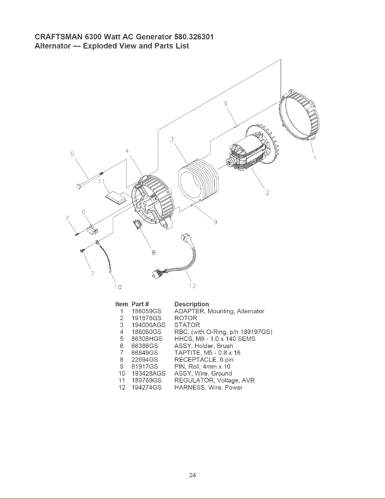
CRAFTSMAN 6300 Watt AC Generator 580.326301
Alternator m E×p[oded View and Parts List
5
\
\
\
\
!!
\
\
\
\
\,
2
/
I
6
7
\
\
\
\
\
\
\
\
\\
9
\
\
10
\
\
12
Item
1
2
3
4
5
6
7
8
9
10
11
12
Part #
186059GS
191876GS
194006AGS
186060GS
86308HGS
66386GS
66849GS
22694GS
81917GS
193428AGS
189769GS
194274GS
Description
ADAPTER, Mounting, Alternator
ROTOR
STATOR
RBC, (with OzRing, p/n 189197GS)
HHCS, M6 z 1.0 x 140 SEMS
ASSY, Holder, Brush
TAPT[TE, M5 _ 0.8 x 16
RECEPTACLE, 6 pin
PIN, Roll, 4mm x 10
ASSY, Wire, Ground
REGULATOR, Voltage, AVR
HARNESS, Wire, Power
24
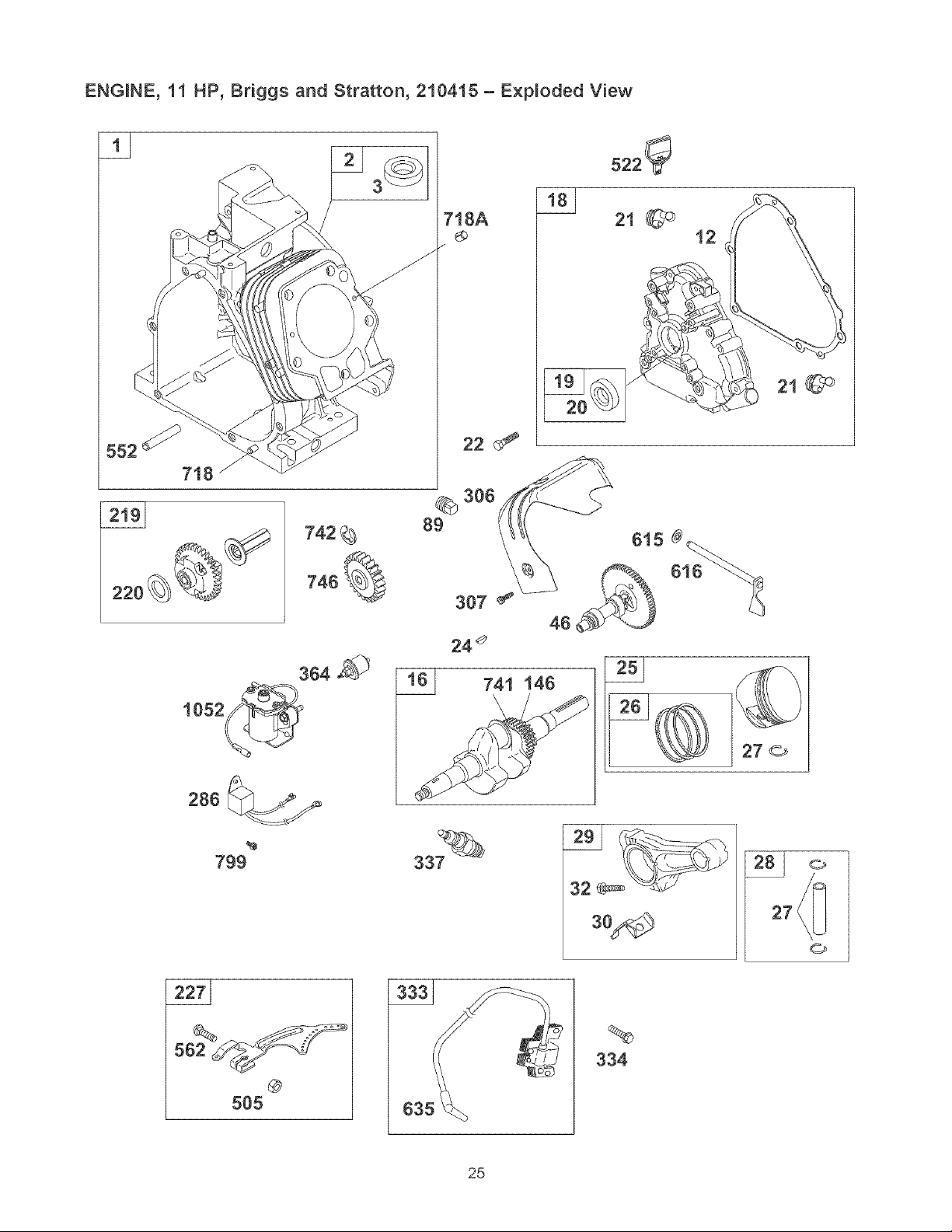
ENGINE, 11 HP, Briggs and Stratton, 210415 - Exploded View
718A
286
%
799
5_ f_
@
5O5
22 _:_
306
89
I
27 o
%
334
25
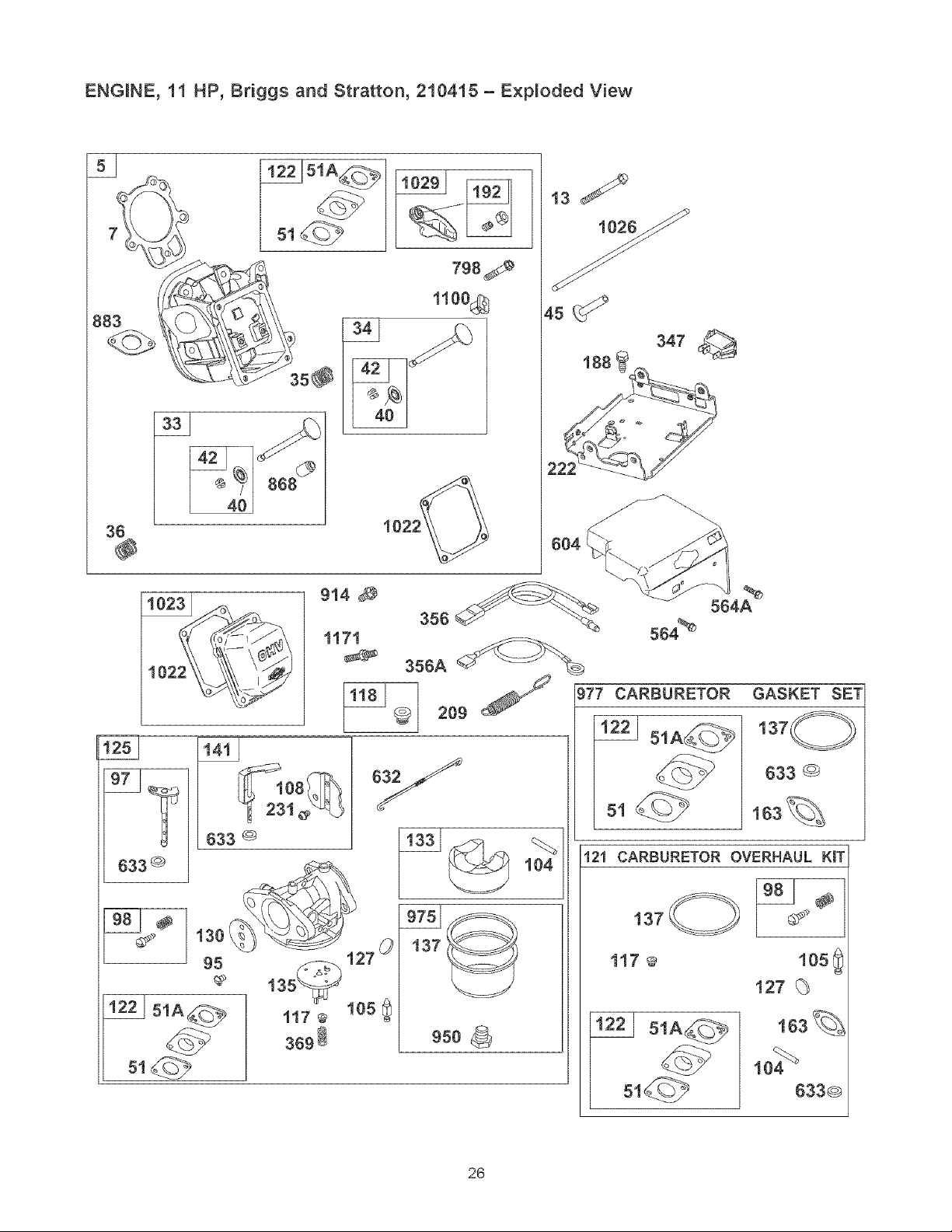
ENGINE, 11 HP, Briggs and Stratton, 210415 - Exploded View
40
868
798_
1100 8
1026_
4s _
347
188
2;
604
36
@
914
1171
1 _L_
633 @
oy
137
9so
%
564A
564 _
977 CARBURETOR
51
GASKET SET
137_
633 @
163_
121 CARBURETOR OVERHAUL KmT
137 _
117 ®
163_
633@
26
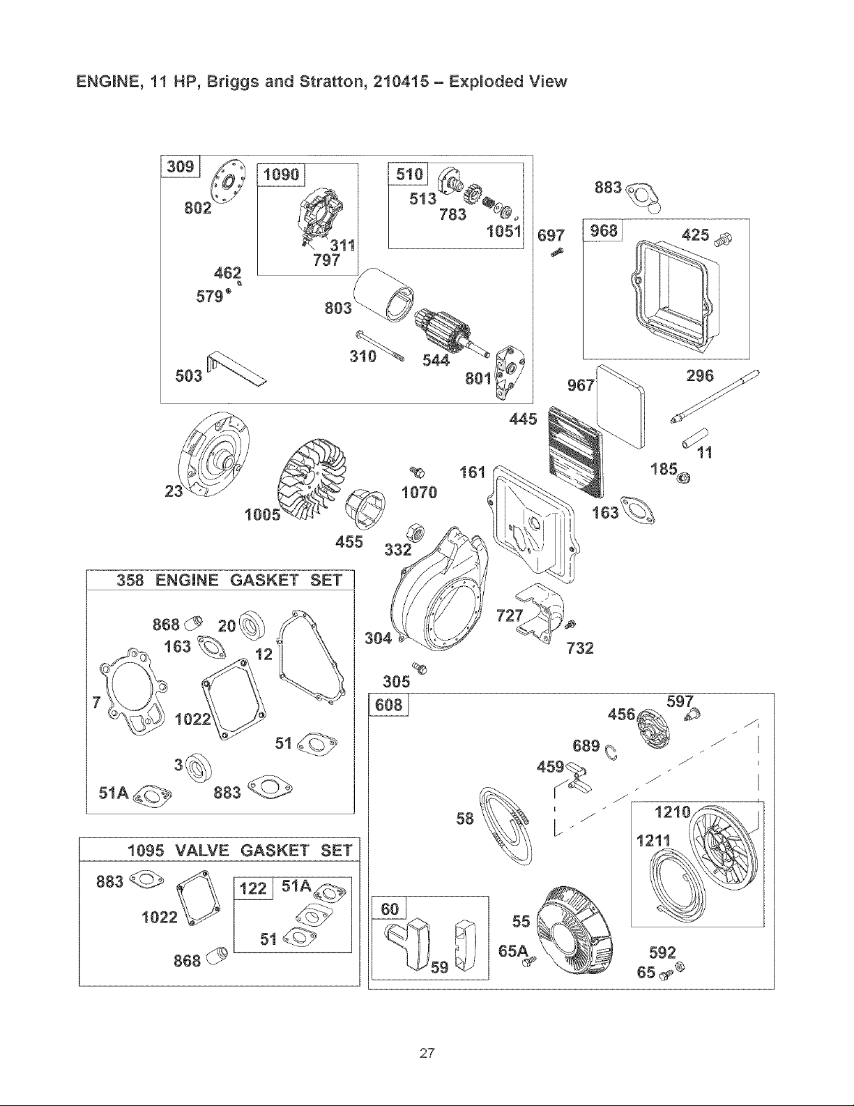
ENGINE, _1 HP, Briggs and Stratton, 210415 - Exploded View
462
579 _
797
503
310_% 544
2 1070
00
455 332_
967
358 ENGINE GASKET SET
8680 2o1
5iA_
883
i095 VALVE GASKET SET
304
%
305
58
732
456
689 %
45_ /
I
i2i0
i21i
592
65 _®
27
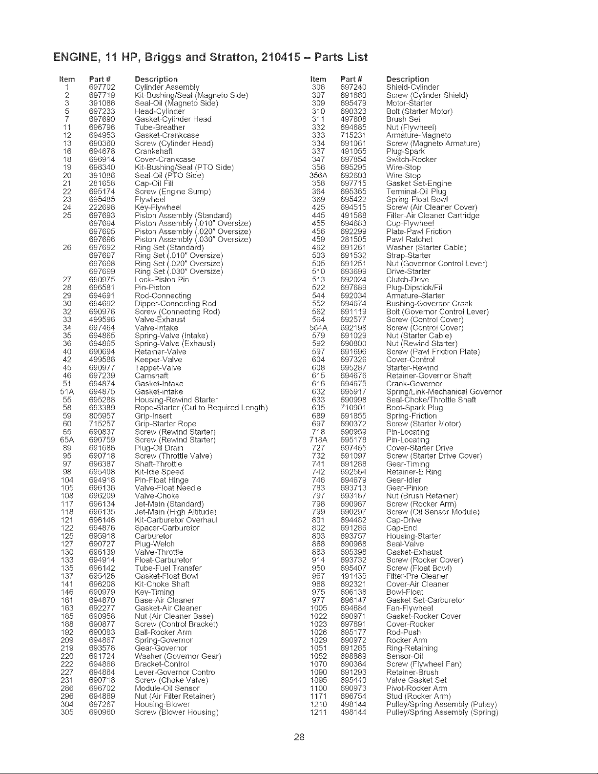
ENGINE, I I
item PaR #
1 697702
2 697719
3 391086
5 697233
7 697690
11 696796
12 694953
13 690360
16 694678
18 696914
19 698340
20 391086
21 281658
22 695174
23 695485
24 222698
25 697693
697694
697695
697696
26 697692
697697
697698
697699
27 690975
28 696581
29 694691
30 694692
32 690976
33 499596
34 697464
35 694865
36 694865
40 690694
42 499586
45 690977
46 697239
51 694874
51A 694875
55 695288
58 693389
59 805957
60 715257
65 690837
65A 690759
89 691686
95 690718
97 696387
98 695408
104 694918
105 696136
108 696209
117 696134
118 696135
121 696146
122 694876
125 695918
127 690727
130 696139
133 694914
135 696142
137 695426
141 696208
146 690979
161 694870
163 692277
185 690958
188 690877
192 690083
209 694867
219 693578
220 691724
222 694866
227 694864
231 690718
286 696702
296 694869
304 697267
305 690960
HP, Briggs and Stratton, 210415 - Parts List
Description item Part #
Cylinder Assembly 306 697240
Kit-Bushing/Seal (Magneto Side) 307 691660
Seal-Oil (Magneto Side) 309 695479
Head-Cylinder 310 690323
Gasket-Cylinder Head 311 497608
Tube-Breather 332 694685
Gasket-Crankcase 333 715231
Screw (Cylinder Head) 334 691061
Crankshaft 337 491055
Cover-Crankcase 347 697854
Kit-Bushing/Seat (PTO Side) 356 695295
Seal-Oil (PTO Side) 356A 692603
Cap-Oil Fitt 358 697715
Screw (Engine Sump) 364 695365
Flywheel 369 695422
Key-Flywheel 425 694515
Piston Assembly (Standard) 445 491588
Piston Assembly (.010" Oversize) 455 694683
Piston Assembly (.020" Oversize) 456 692299
Piston Assembly (.030" Oversize) 459 281505
Ring Set (Standard) 462 691261
Ring Set (.010" Oversize) 503 691532
Ring Set (.920" Oversize) 505 691251
Ring Set (.030" Oversize) 510 693699
Lock-Piston Pin 513 692024
Pin-Piston 522 697689
Rod-Connecting 544 692034
Dipper-Connecting Rod 552 694674
Screw (Connecting Rod) 562 691119
Valve-Exhaust 564 692577
Valve-Intake 564A 692198
Spring-Valve (intake) 579 691029
Spring-Valve (Exhaust) 592 690800
Retainer-Valve 597 691696
Keeper-Valve 604 697326
Tappet-Valve 608 695287
Camshaft 615 694676
Gasket-intake 616 694675
Gasket-intake 632 695917
Housing-Rewind Starter 633 690998
Rope-Starter (Cut to Required Length) 635 710901
Grip-Insert 689 691855
Grip-Starter Rope 697 690372
Screw (Rewind Starter) 718 690959
Screw (Rewind Starter) 718A 695178
Plug-Oil Drain 727 697465
Screw (Throttle Valve) 732 691097
Shaft-Throttle 741 691288
Kit-Idle Speed 742 692564
Pin-Float Hinge 746 694679
Valve-Float Needle 783 693713
Valve-Choke 797 693167
Jet-Main (Standard) 798 690967
Jet-Main (High Altitude) 799 690297
Kit-Carburetor Overhaul 801 694482
Spacer-Carburetor 802 691286
Carburetor 803 693757
Plug-Welch 868 690968
Valve-Throttle 883 695398
Float-Carburetor 914 693732
Tube-Fuel Transfer 950 695407
Gasket-Float Bowl 967 491435
Kit-Choke Shaft 968 692321
Key-Timing 975 696138
Base-Air Cleaner 977 696147
Gasket-Air Cleaner 1005 694684
Nut (Air Cleaner Base) 1022 690971
Screw (Control Bracket) 1023 697691
Bait-Rocker Arm 1026 695177
Spring-Governor 1029 690972
Gear-Governor 1051 691265
Washer (Governor Gear) 1052 698869
Bracket-Control 1070 690364
Lever-Governor Control 1090 691293
Screw (Choke Valve) 1095 695440
Module-Oil Sensor 1100 690973
Nut (Air Filter Retainer) 117I 696754
Housing-Blower 1210 498144
Screw (Blower Housing) 1211 498144
Description
Shield-Cylinder
Screw (Cylinder Shield)
Motor-Starter
Bolt (Starter Motor)
Brush Set
Nut (Flywheel)
Armature-Magneto
Screw (Magneto Armature)
Plug-Spark
Switch-Rocker
Wire-Stop
Wire-Stop
Gasket Set-Engine
Terminal-Oil Plug
Spring-Float Bowl
Screw (Air Cleaner Cover)
Filter-Air Cleaner Cartridge
Cup-Flywheel
Plate-Pawt Friction
PawI-Ratchet
Washer (Starter Cable)
Strap-Starter
Nut (Governor Control Lever)
Drive-Starter
Clutch-Drive
Plug-Dipstick/Fill
Armature-Starter
Bushing-Governor Crank
Bolt (Governor Control Lever)
Screw (Control Cover)
Screw (Controt Cover)
Nut (Starter Cable)
Nut (Rewind Starter)
Screw (Pawl Friction Plate)
Cover-Control
Starter-Rewind
Retainer-Governor Shaft
Crank-Governor
Spring/Link-Mechanical Governor
Seat-Choke/Throttle Shaft
Boot-Spark Plug
Spring-Friction
Screw (Starter Motor)
Pin-Locating
Pin-Locating
Cover-Starter Drive
Screw (Starter Drive Cover)
Gear-Timing
Retainer-E Ring
Gear-idler
Gear-Pinion
Nut (Brush Retainer)
Screw (Rocker Arm)
Screw (Oil Sensor Module)
Cap-Drive
Cap-End
Housing-Starter
Seat-Valve
Gasket-Exhaust
Screw (Rocker Cover)
Screw (Float Bowl)
Filter-Pre Cleaner
Cover-Air Cleaner
Bowl-Float
Gasket Set-Carburetor
Fan-Flywheel
Gasket-Rocker Cover
Cover-Rocker
Rod-Push
Rocker Arm
Ring-Retaining
Sensor-Oil
Screw (Flywheel Fan)
Retainer-Brush
Valve Gasket Set
Pivot-Rocker Arm
Stud (Rocker Arm)
Pulley/Spring Assembly (Puttey)
Pulley/Spring Assembly (Spring)
28

29
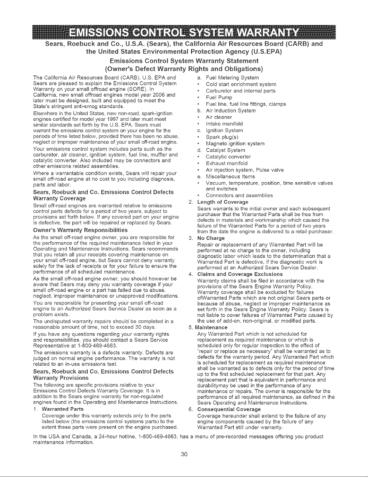
Sears, Roebuck and Co., U.S.A. (Sears), the California Air Resources Board (CARE}) and
the United States Environmenta_ Protection Agency (U.S.EPA)
Emissions Contro_ System Warranty Statement
(Owner's Defect Warranty Rights and Obligations)
The California Air Resources Board (CARB), U.S. EPA and
Sears are pleased to explain the Emissions Control System
Warranty on your small offroad engine (SORE). In
California, new small offroad engines model year 2006 and
later must be designed, built and equipped to meet the
State's stringent anti-smog standards.
Elsewhere in the United States, new non-road, spark-ignition
engines certified for model year 1997 and later must meet
similar standards set forth by the U.S. EPA. Sears must
warrant the emissions control system on your engine for the
periods of time listed below, provided there has been no abuse,
neglect or improper maintenance of your small off-road engine.
Your emissions control system includes parts such as the
carburetor, air cleaner, ignition system, fuel line, muffler and
catalytic converter. Also included may be connectors and
other emissions related assemblies.
Where a warrantable condition exists, Sears will repair your
small off-road engine at no cost to you including diagnosis,
parts and labor.
Sears, Roebuck and Co. Emissions Contro_ Defects
Warranty Coverage
Small off-road engines are warranted relative to emissions
control parts defects for a period of two years, subject to
provisions set forth below. If any covered part on your engine
is defective, the part will be repaired or replaced by Sears.
Owner's Warranty Responsibilities
As the small off-road engine owner, you are responsible for
the performance of the required maintenance listed in your
Operating and Maintenance Instructions. Sears recommends
that you retain a]! your receipts covering maintenance on
your small off-road engine, but Sears cannot deny warranty
solely for the lack of receipts or for your failure to ensure the
performance of all scheduled maintenance.
As the small off-road engine owner, you should however be
aware that Sears may deny you warranty coverage if your
small off-road engine or a part has failed due to abuse,
neglect, improper maintenance or unapproved modifications.
You are responsible for presenting your small off-road
engine to an Authorized Sears Service Dealer as soon as a
problem exists.
The undisputed warranty repairs should be completed in a
reasonable amount of time, not to exceed 30 days.
If you have any questions regarding your warranty rights
and responsibilities, you should contact a Sears Service
Representative at 1-800-469-4663.
The emissions warranty is a defects warranty. Defects are
judged on normal engine performance. The warranty is not
related to an in-use emissions test.
Sears, Roebuck and Co. Emissions Control Defects
Warranty Provisions
The following are specific provisions relative to your
Emissions Control Defects Warranty Coverage. It is in
addition to the Sears engine warranty for non-regulated
engines found in the Operating and Maintenance Instructions.
1, Warranted Parts
Coverage under this warranty extends only to the parts
listed below (the emissions control systems parts) to the
extent these parts were present on the engine purchased.
a. Fuel Metering System
Cold start enrichment system
Carburetor and internal parts
Fuel Pump
Fuel line, fuel line fittings, clamps
b. Air induction System
Air cleaner
intake manifold
c. Ignition System
Spark plug(s)
Magneto ignition system
d. Catalyst System
Catalytic converter
Exhaust manifold
Air injection system, Pulse valve
e. Miscellaneous Items
Vacuum, temperature, position, time sensitive valves
and switches
Connectors and assemblies
2. Length of Coverage
Sears warrants to the initial owner and each subsequent
purchaser that the Warranted Parts shall be free from
defects in materials and workmanship which caused the
failure of the Warranted Parts for a period of two years
from the date the engine is delivered to a retail purchaser.
3. No Charge
Repair or replacement of any Warranted Part will be
performed at no charge to the owner, including
diagnostic labor which leads to the determination that a
Warranted Part is defective, if the diagnostic work is
performed at an Authorized Sears Service Dealer.
4. Claires and Coverage Excmusions
Warranty claims shall be flied in accordance with the
provisions of the Sears Engine Warranty Policy.
Warranty coverage shall be excluded for failures
of Warranted Parts which are not original Sears parts or
because of abuse, neglect or improper maintenance as
set forth in the Sears Engine Warranty Policy. Sears is
not liable to cover failures of Warranted Parts caused by
the use of add-on, non-original, or modified parts.
5. Maintenance
Any Warranted Part which is not scheduled for
replacement as required maintenance or which is
scheduled only for regular inspection to the effect of
'repair or replace as necessary" shah be warranted as to
defects for the warranty period. Any Warranted Part which
is scheduled for replacement as required maintenance
shall be warranted as to defects only for the period of time
up to the first scheduled replacement for that part. Any
replacement part that is equivalent in performance and
durabilitymay be used in the performance of any
maintenance or repairs. The owner is responsible for the
performance of a!] required maintenance, as defined in the
Sears Operating and Maintenance Instructions.
6. Consequential Coverage
Coverage hereunder shall extend to the failure of any
engine components caused by the failure of any
Warranted Part still under warranty.
In the USA and Canada, a 24-hour hotline, 1-800-469-4663, has a menu of pre-recorded messages offering you product
maintenance information.
3O
Emissions Durability Period and Air index
Information On Your Engine Emissions Labe_
Engines that are certified to meet the California Air
Resources Board (CARB) Tier 2 Emission Standards must
display information regarding the Emissions Durability Period
and Air Index. The engine manufacturer makes this
information available to the consumer on emission labels.
The Emissions Durability Period describes the number of
hours of actual running time for which the engine is certified
to be emissions compliant, assuming proper maintenance in
accordance with the Operating & Maintenance Instructions.
The following categories are used:
Moderate: Engine is certified to be emission compliant for
125 hours of actual engine running time.
Intermediate: Engine is certified to be emission compliant
for 250 hours of actual engine running time.
Extended: Engine is certified to be emission compliant for
500 hours of actual engine running time.
For example, a typical walkobehind lawn mower is used
20 to 25 hours per year. Therefore, the Emissions
Durability Period of an engine with an intermediate rating
would equate to 10 to 12 years.
The Air hdex is a calculated number describing the relative
level of emissions for a specific engine family. The lower the
Air Index, the cleaner the engine. This information is
displayed in graphical form on the emisions labe!.
Emissions Compliance Period On Engine
Emissions Compliance Labe_
After July 1,2000 certain Sears engines will be certified to
meet the United States Environmental Protection Agency
(USEPA) Phase 2 emission standards. For phase 2 certified
engines, the Emissions Compliance Period referred to on
the Emissions Compliance labe! indicates the number of
operating hours for which the engine has been shown to
meet Federal emission requirements. For engines less than
225 cc displacement, Category' C = 125 hours, B = 250
hours and A = 500 hours. For engines of 225 cc or more,
Category C = 250 hours, B = 500 hours and A = 1000 hours.
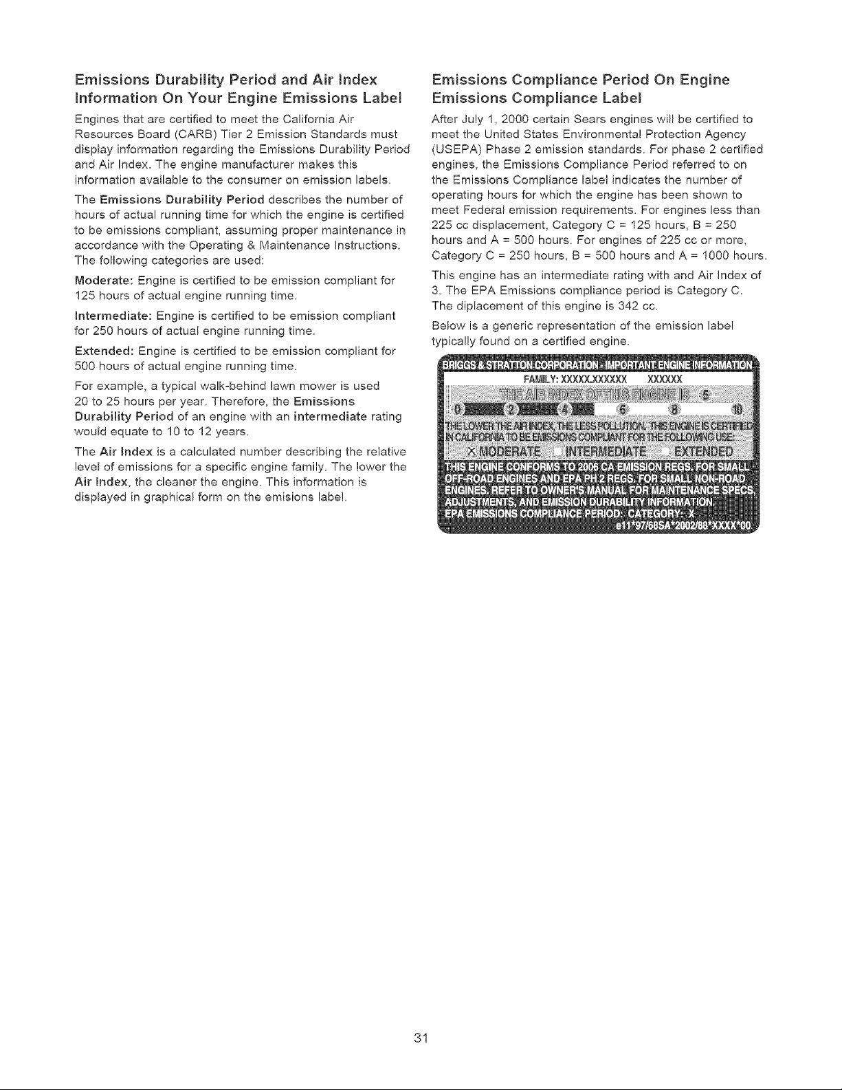
This engine has an intermediate rating with and Air Index of
3. The EPA Emissions compliance period is Category C.
The diplacement of this engine is 342 cc.
Below is a generic representation of the emission label
typically found on a certified engine.
31
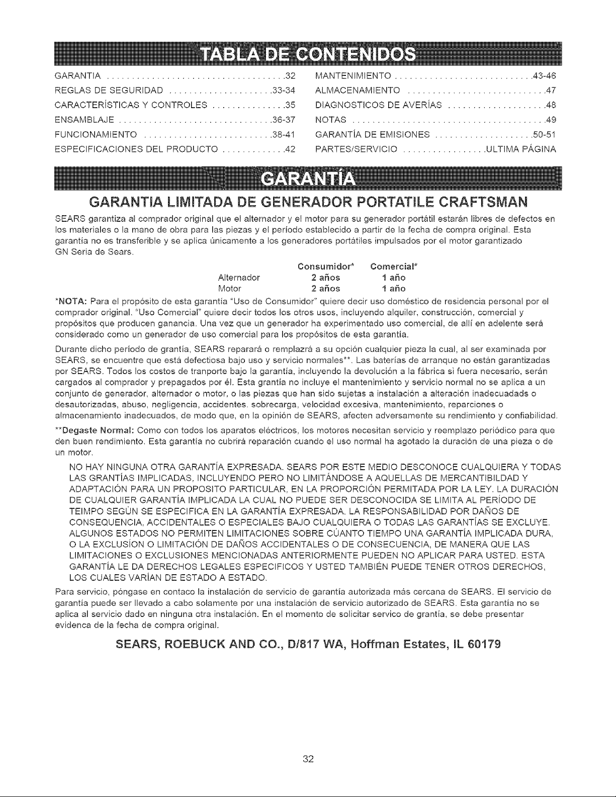
GARANTJA .................................... 32
REGLAS DE SEGURIDAD ..................... 33°34
CARACTERJSTICAS Y CONTROLES ............... 35
ENSAMBLAJE ............................... 36°37
FUNCIONAMIENTO .......................... 38o41
ESPECIFICACIONES DEL PRODUCTO ............. 42
MANTENIMIENTO ............................ 43-46
ALMACENAMIENTO ............................ 47
DIAGNOSTICOS DE AVERJAS .................... 48
NOTAS ....................................... 49
GARANTJA DE EMLSIONES .................... 50-51
PARTES/SERVICIO ................. ULTJMA PAGINA
GARANTIA LIMiTADA DE GENERADOR PORTATtLE CRAFTSMAN
SEARS garantiza al comprador original que el altemador y el motor para su generador portati! estaran Iibres de defectos en
los materiales o la mano de obra para las piezas y el periodo establecido a partir de la fecha de compra original. Esta
garantia no es transferibie y se aplica Onicamente a los generadores portatiles impulsados por el motor garantizado
GN Seria de Sears.
Consumidor* Comercial*
Altemador 2 a_os 1 a_o
Motor 2 a_os 1 a_o
*NOTA: Para el prop6sito de esta garantla "Uso de Consumidor" quiere decir uso dom6stico de residencia personal por el
comprador original 'Uso Comercial" quiere decir todos los otros usos, incluyendo alquiler, construcci6n, comercial y
prop6sitos que producen ganancia. Una vez que un generador ha experimentado uso comercial, de a!li en adelente sera
considerado como un generador de uso comercial para los prop6sitos de esta garantia.
Durante dicho periodo de grantia, SEARS reparara o remplazra a su opci6n cualquier pieza la cual, a! ser examinada por
SEARS, se encuentre que esta defectiosa bajo uso y servicio normales**_ Las baterias de arranque no estan garantizadas
por SEARS. Todos los costos de tranporte bajo la garantia, incluyendo la devoluci6n a la fabrica si fuera necesario, seran
cargados al comprador y prepagados por 61. Esta grantia no incluye el mantenimiento y servicio normal no se aplica a un
conjunto de generador, alternador o motor, o las piezas que han sido su]etas a instalaci6n a alteraci6n inadecuadads o
desautorizadas, abuso, negligencia, accidentes, sobrecarga, velocidad excesiva, mantenimiento, reparciones o
almacenamiento inadecuados, de modo que, en la opini6n de SEARS, afecten adversamente su rendimiento y confiabilidad.
**Degaste Normal: Como con todos los aparatos el6ctricos, los motores necesitan servicio y reemplazo peri6dico para que
den buen rendimiento. Esta garantla no cubrira reparaci6n cuando el uso normal ha agotado la duraci6n de una pieza o de
un motor.
NO HAY NINGUNA OTRA GARANTiA EXPRESADA. SEARS POR ESTE MEDIO DESCONOCE CUALQUIERA Y TODAS
LAS GRANTJAS IMPLICADAS, INCLUYENDO PERO NO LIMtT_.NDOSE A AQUELLAS DE MERCANTiBILDAD Y
ADAPTACION PARA UN PROPOSITO PARTICULAR, EN LA PROPORCION PERMITADA POR LA LEY. LA DURACJON
DE CUALQUIER GARANTJA IMPLICADA LA CUAL NO PUEDE SER DESCONOCIDA SE LIMITA AL PERiODO DE
TEIMPO SEGON SE ESPECIFICA EN LA GARANTiA EXPRESADA. LA RESPONSABILIDAD POR DAI(IOS DE
CONSEQUENCIA, ACCIDENTALES O ESPECIALES BAJO CUALQUIERA O TODAS LAS GARANTJAS SE EXCLUYE
ALGUNOS ESTADOS NO PERMITEN LIMITACIONES SOBRE COANTO TEMPO UNA GARANTJA IMPLICADA DURA,
O LA EXCLUSION O LIMITACION DE DA!'4OS ACCIDENTALES O DE CONSECUENCIA, DE MANERA QUE LAS
LIMITACIONES O EXCLUS!ONES MENCIONADAS ANTERIORMENTE PUEDEN NO APLICAR PARA USTED. ESTA
GARANTJA LE DA DERECHOS LEGALES ESPECIFICOS Y USTED TAMBI#N PUEDE TENER OTROS DERECHOS,
LOS CUALES VARJAN DE ESTADO A ESTADO.
Para servicio, p6ngase en contaco la instalaci6n de servicio de garantia autorizada mas cercana de SEARS. El servicio de
garantia puede ser Ilevado a cabo solamente por una instalaci6n de servicio autorizado de SEARS. Esta garantia no se
aplica al servicio dado en ninguna otra instalaci6n. En e! momento de solicitar servico de grantia, se debe presentar
evidenca de la fecha de compra original.
SEARS, ROEBUCK AND CO., D1817 WA, Hoffman Estates, JL 60179
32
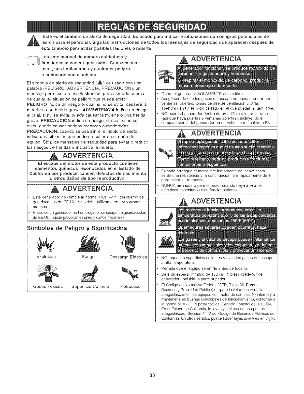
Este es e[ simbo[o de a[erta de seguridad. Es usado para indicar[e situaciones con pe[igros potencia[es de
lesion para e[ persona[. Siga [as instrucciones de todos los mensajes de seguridad que aparecen despues de
este simbo[o para evitar posib[es [esiones o muerte.
Leaesteman°a,demaoeraco,dadosay
[__l_J;J..... fami[iar[cese con su generador. Conozca sus
usos, sus Hmitaciones y cua[quier peJigro
re[acionado con e[ mismo.
El simbolo de alerta de seguridad (,_) es usado con una
palabra (PELiGRO, ADVERTENCJA, PRECAUCION), un
mensaje por escrito o una ilustraci6n, para alertarlo acerca
de cua[quier situaciTn de peligro que pueda existir.
PEL[GRO indica un riesgo el cual, si no se evita, eausar& la
muerte o una hedda grave. ADVERTENCIA indica un riesgo
el cual, si no se evita, puede causar la muerte o una herida
grave. PRECAUCJ6N indica un riesgo, e! cual, si no se
evita, puede causar heridas menores o moderadas.
PRECAUCI6N, cuando se usa sin el s[mbolo de alerta,
indica una situaci6n que podr[a resultar en el daffo del
equipo. Siga los mensajes de seguddad para evitar o reducir
los riesgos de heridas e inclusive la muerte.
A
E[ escape de[ motor de este producto contiene
eiementos quimicos reconocidos en el Estado de
California pot producir c&ncer, defectos de nacimiento
u otros daSos de tipo reproductivo.
ADVERTENCJA
• Este generador no cumple la norma 33CFR-183 del cuerpo de
guardacostas de EE.UU. y no debe utilizarse en aplicaciones
marinas.
• El use de un generador no homologado por cuerpo de guardacostas
de EE.UU. puede provocar tesiones y da_os materiales.
S[mbo[os de Pe[igro y Significados
Explosi6n Fuego Descarga Electrica
Gases T6xicos Superficie Ca[iente Retroceso
ADVERTENC[A
Opere et generador SOLAMENTE al aire libre.
AsegL_rese de que los gases de escape no puedan entrar por
ventanas, puertas, tomas de aire de ventilaciOn u otras
aberturas en un espacio cerrado en el que puedan acumularse.
NO opere et generador dentro de un edificio o lugar cerrado
(aunque haya puertas o ventanas abiertas), incluyendo e!
compartimiento del generador en un vehicu!o recreativo o RV.
Cuando arranque eI motor, tire tentamente dei cane hasta
sentir una resistencia y, a continuaci6n, tire rapidamente de 61
para evitar su retroceso.
NUNCA arranque o pare el motor cuando haya aparatos
el6ctricos conectados y en funcionamiento.
, kADVERTENC[A
NO toque las superficies catientes y evite los gases del escape
a alta temperatura.
Permita que el equipo se enfrfe antes de tocarto.
Deje un espacio minimo de 152 cm (5 pies) alrededor del
generador, incluida la parte superior.
EI C(_digo de Normativa FederaI (CFR, Titulo 36: Parques,
Bosques y Propiedad PObtica) obliga a instalar una pantatla
apagachispas en tos equipos con motor de combusti6n interno y a
mantenerla en buenas condiciones de funcionamiento, conforme a
ta norma 5100-1C (o posterior) det Servicio ForestaI de la USDA.
En et Estado de California, la ley exige el uso de una pantatla
apagachispas (SecciOn 4442 del C6digo de Recursos POblicos de
California). En otros estados puede haber teyes similares en vigor.
33
ADVERTENCIA
Cuando use un generador como poder de energia auxiliar, notifique
a ta compa_ia de utilidades. Use et equipo de transferencia
aprobado para aistar et generador de otra utilidad et@ctrica.
Use un interruptor para la falla del circuito de tierra (GFCI) en
cualquier area bastante hQmeda o que sea altamente conductiva,
tales como terrazas de metal o trabajo hecho con acero.
NO toque los alambres pelados o receptacutos.
NO use un generador con cables et6ctricos que est6n
malgastados, rotos, pelados o da_ados de cuatquier forma.
NO opere et generador bajo la Ituvia.
NO maneje el generador o cables electdcos mientras est¢ parado
en agua, descatzo o cuando las manos y los pies est6n mojados.
NO permita que personas descalificadas o ni_os operen o
sirvan al generador.
ADVERTENCIA
CUANDO ANADA CO_vtBUSTIBLE O VACiE EL
DEP6SITO
Apague et generador (posici6n OFF) y d6jelo enfriar al menos por
2 minutos antes de remover ta tapa de ta combustible. Afloje ta
tapa lentamente para dejar que la presi6n salga del tanque.
Uene o vacie el dep6sito de combustible a la intemperie.
NO tlene demasiado et tanque. Permita at menos espacio para
la expansi6n det combustible.
Mantenga la combustible atejada de chispas, llamas abiertas,
pilotos, calory otras fuentes de ignici6n.
NO encienda un cigarritto o fume.
CUANDO PONGA EN FUNCIONAMmENTO EL EQUIPO
Compruebe que ta bujia, et silenciador, et tap6n del dep6sito de
combustible y et filtro de aire estan instalados.
NO arranque el motor sin la bujia instalada.
Si se ha derramado combustible, espere a que se evapore
antes de arrancar el motor.
CUANDO OPERE EL EQU_PO
NO incline el motor o et equipo, de tat manera que ta
combustible se pueda derramar.
NO estrangute el carburador para parar et motor.
Este generador no es apto para el uso en equipos m6viles ni en
aplicaciones marinas.
CUANDO TRANSPORTE O REPARE EL EQUIPO
Transporte o repare el equipo con et tanque de combustible vacio, o
con ta valvula para apagar et combustible, apagada (posici6n OFF).
Desconecte el cable de ta bujia.
CUANDO ALMACENE O GUARDE EL EQUIPO CON
COMBUSTIBLE EN EL TANQUE
Atmacene aJejado de calderas, estufas, calentadores de agua,
secadoras de ropa u otros aparatos etectrodom6sticos que
posean pitotos u otras fuentes de ignici6n, porque ettos pueden
encender tos vapores de la combustible.
CUANDO AJUSTE O HAGA REPARACIONES A SU
GENERADOR
• Siempre desconecte et atambre de ta bujia y col6quelo donde
no pueda entrar en contacto con la bujia.
CUANDO PRUEBE LA BUJiA DEL MOTOR
Utitice un comprobador de bujias homotogado.
NO comprueba la chispa sin la bujia instalada.
PRECAUCtON
No cambie ninguna vetocidad determinada. El generador
suministra una frecuencia y un voltaje calificado cuando
funciona a una velocidad determinada.
No modifique al generador en ninguna forma.
PRECAUCION
Vea "No sobrecargue generador".
Encienda su generador y deje que et motor se estabitice antes
de conectar las cargas et6ctricas.
Conecte ias cargas el@ctricas en ta posici6n de apagado (OFF),
tuego encienda (ON) para su operaci6n.
Apague (OFF) tas cargas el6ctricas y desconectelas del
generador antes de parar el generador.
Use el generador solamente con ta finatidad para el cual rue
dise_ado.
Si usted tiene atguna pregunta acerca de las finalidades de uso
det generador, pregQntete a su concesionario o contacte a
Sears.
Opere et generador solamente en superficies nivetadas.
NO exponga at generador a una humedad excesiva, polvo,
suciedad o vapores corrosivos.
NO inserte cualquier objeto a trav6s de tas ranuras de
enfriamiento.
Si los aparatos conectados se sobrecalientan, apaguetos y
descon6ctetos det generador.
Apague el generador si:
-Se pierde la salida el6ctrica;
-El equipo produce chispas, humo o emite llamas;
-La unidad vibra de una manera excesiva.
34
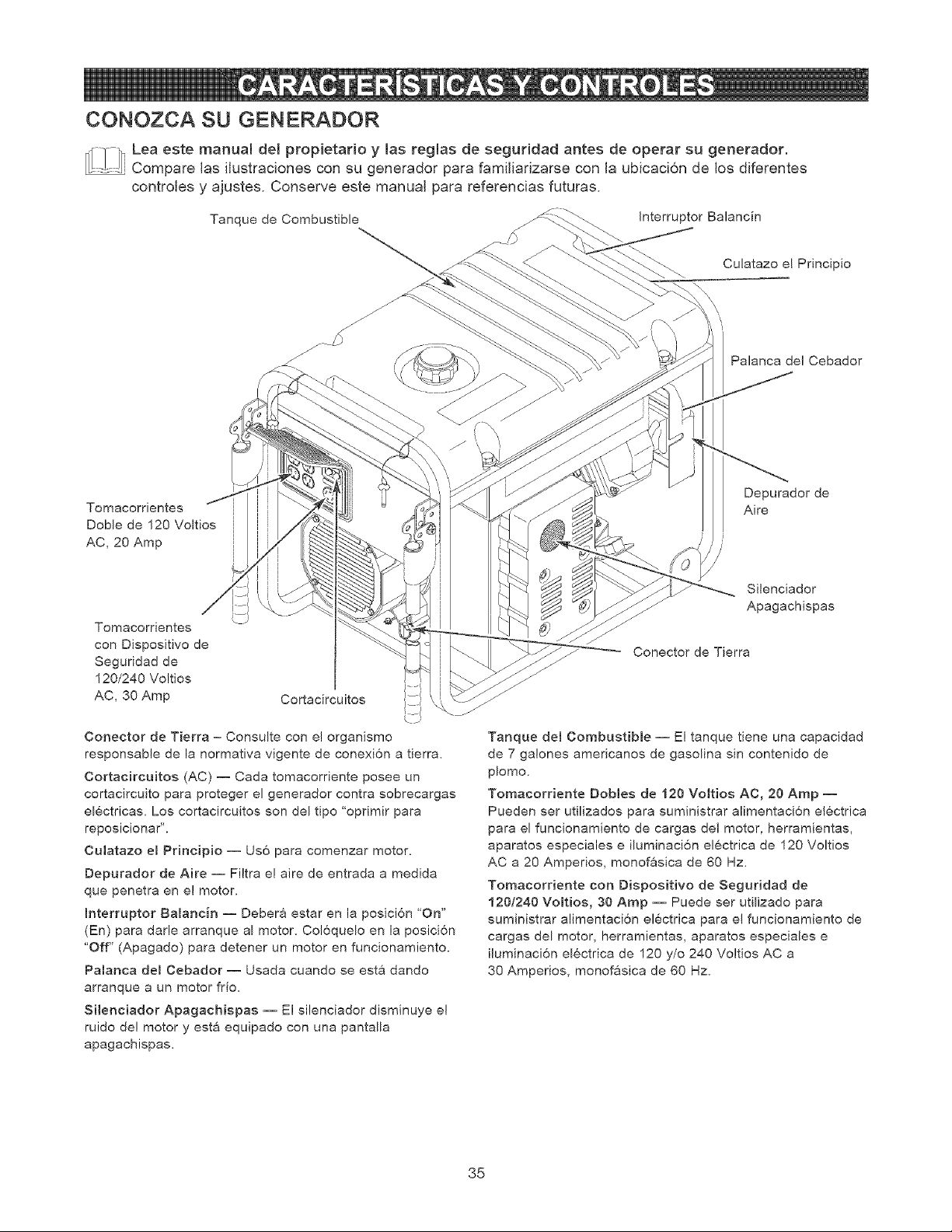
CONOZCA SU GENERADOR
[_ii! _ Lea este manuaJ del propietario y las reglas de segurJdad antes de operar su generador.
__ Compare las iJustraciones con su generador para famiJiadzarse con la ubicaci6n de los diferentes
controles y ajustes. Conserve este manuaJ para referencias futuras.
Tanque de Combustible
Interruptor Balanc[n
Culatazo eL Principio
Palanca de! Cebador
Tomacorrientes
Doble de 120 Voltios
AC, 20 Amp
Depurador de
Aire
Tomacorrientes
con Dispositivo de
Seguridad de
120/240 Voltios
AC, 30 Amp
Conector de Tierra - Consulte con e! organismo
responsable de la normativa vigente de conexi6n a tierra.
Cortacircuitos (AC) -- Cada tomacorriente posee un
cortacircuito para proteger el generador contra sobrecargas
electricas. Los cortacircuitos son del tipo "oprimir para
reposicionar".
Culatazo em Principio -- Uso para comenzar motor.
Depurador de Aire -- Filtra e! aire de entrada a medida
que penetra en el motor.
[nterruptor BaJanc[n -- Debera estar en la position 'On"
(En) para darle arranque al motor. Col6quelo en la posici6n
"Off" (Apagado) para detener un motor en funcionamiento.
Pamanca del Cebador -- Usada cuando se est& dando
arranque a un motor fr[o.
Silenciador Apagachispas -- El silenciador disminuye el
ruido de! motor y est& equipado con una pantalla
apagachispas.
Silenciador
Apagachispas
Conector de Tierra
Tanque del CombustibJe -- El tanque tiene una capacidad
de 7 galones americanos de gasolina sin contenido de
plomo.
Tomacorriente Dobles de 120 Voltios AC, 20 Amp --
Pueden ser util[zados para suministrar alimentaci6n electrica
para el funcionamiento de cargas del motor, herramientas,
aparatos especiales e iluminaci6n electrica de 120 Voltios
AC a 20 Amperios, monofasica de 60 Hz.
Tomacorriente con Dispositivo de Seguridad de
120!240 VoJtios, 30 Amp -- Puede ser utilizado para
suministrar alimentaci6n electrica para el funcior_amiento de
cargas del motor, herramientas, aparatos especiales e
iluminaci6n electrica de 120 y/o 240 Voltios AC a
30 Amperios, monofasica de 60 Hz.
35
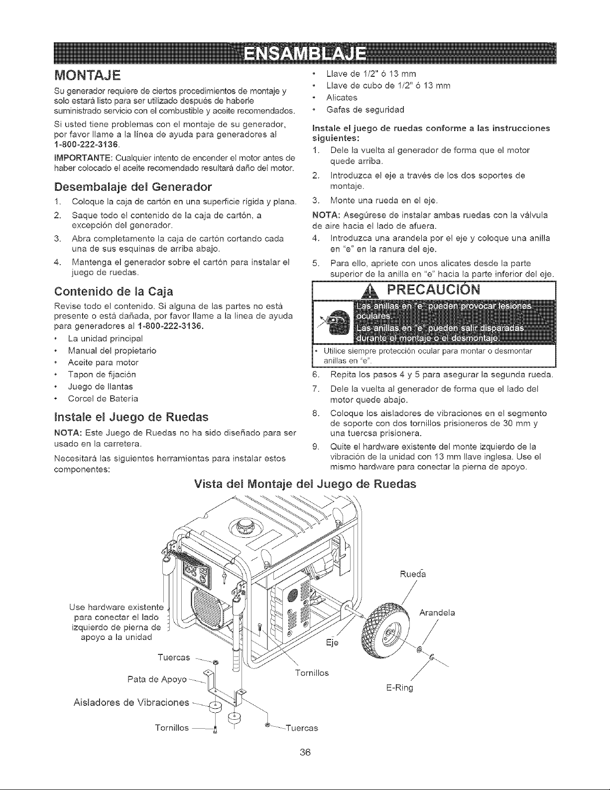
Su generador requiere de ciertos procedimientos de montaje y
solo estara listo para ser utilizado despues de haberle
suministrado servicio con el combustible y aceite recomendados.
Si usted tiene problemas con el montaje de su generador,
por favor Ilame a la linea de ayuda para generadores al
1 o800o222o3136.
IMPORTANTE: Cualquier intento de encender el motor antes de
haber co!ocado e! aceite recomendado resultara dafio del motor,
Desembalaje del Generador
1, Coloque la caja de cart6n en una superficie dgida y plan&
2. Saque todo e! contenido de la caja de cart6n, a
excepci6n del generador.
3. Abra completamente la caja de cart6n cortando cada
una de sus esquinas de arriba abajo.
4. Mantenga el generador sobre el cart6n para instalar el
juego de ruedas.
Contenido de la Caja
Revise todo el contenido, Si alguna de las partes no esta
presente o esta dafiada, por favor !lame a la linea de ayuda
para generadores al 1o800o222o3136.
La unidad principal
Manual del propietario
Aceite para motor
Tapon de fijaci6n
Juego de Ilantas
Corcel de Bateda
Instate e_ Juego de Ruedas
NOTA: Este Juego de Ruedas no ha sido disefiado para ser
usado en la carretera.
Necesitara las siguientes herramientas para instalar estos
componentes:
Llave de 1/2" 6 13 mm
Llave de cubo de 1/2" 6 13 mm
Alicates
Gafas de seguridad
Instale el juego de ruedas conforrne alas instrucciones
siguientes:
1. Dele la vuelta al generador de forma que el motor
quede arriba.
2. Introduzca el eje a traves de los dos soportes de
montaje.
3. Monte una rueda en el eje.
NOTA: AsegOrese de instalar ambas ruedas con la valvula
de aire hacia el lado de afuera.
4. Introduzca una arandela por e! eje y co!oque una anilla
en "e" en la ranura del eje.
5. Para ello, apriete con unos alicates desde la parte
superior de la anilla en "e" hacia la parte inferior del eje.
PRECAUCI6N
Utitice siempre protecciOn ocular para montar o desmontar
aniilas en 'e'.
6. Repita los pasos 4 y 5 para asegurar la segunda rueda.
7. Dele la vuelta al generador de forma que el lado del
motor quede abajo,
8. Coloque los aisladores de vibraciones en el segmento
de soporte con dos tomillos prisioneros de 30 mm y
una tuercsa prisionera.
9, Quite el hardware existente del monte izquierdo de la
vibraci6n de la unidad con 13 mm Ilave inglesa. Use el
mismo hardware para conectar la pierna de apoyo.
Vista de_ Montaje de_ Juego de Ruedas
Rueda
Use hardware existent_
para conectar el lado
izquierdo de pierna de
apoyo a la unidad
Pata de A
Aisladores de Vibraciones __
Eie
Tornillos
Arandela
/
>
EoRing
-Tuercas
36
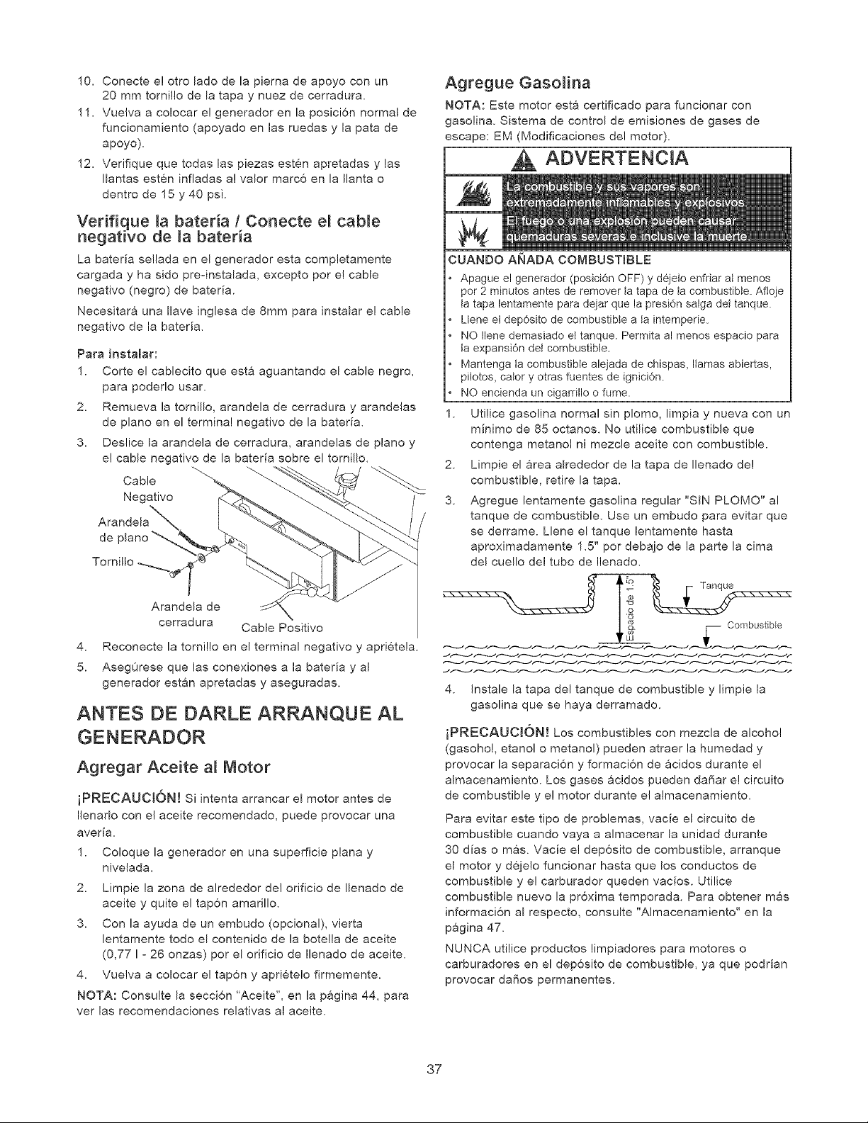
10. Conecte e! otro lado de la pierna de apoyo con un
20 mm torni!lo de la tapa y nuez de cerradura.
11. Vuelva a colocar e! generador en la posicion normal de
funcionamiento (apoyado en las ruedas y la pata de
apoyo).
12. Verifique que todas las piezas esten apretadas y las
Ilantas esten infladas a! valor marco en la Ilanta o
dentro de 15 y 40 psi.
Verifique _a bateria / Conecte e_ cable
negativo de la bateda
La bateria se!lada en el generador esta compietamente
cargada y ha sido pre-instalada, excepto por el cable
negativo (negro) de bateria.
Necesitara una Ilave inglesa de 8mm para instalar e! cable
negativo de la bateria.
Para instalar:
1. Carte el cablecito que est& aguantando el cable negro,
para podeflo usar.
2. Remueva la tornillo, arandela de cerradura y arandelas
de piano en el terminal negativo de la bateria.
3. Deslice la arandela de cerradura, arandelas de piano y
e! cable negativo de la bateria sobre el tornillo.
Cable _
Negativo
Arandela
de
4.
5.
Arandela de
cerradura Cable Positivo
Reconecte la tomi!lo en el terminal negativo y aprietela.
AsegOrese que las conexiones a la bateria y al
generador estan apretadas y aseguradas.
ANTES DE DARLE ARRANQUE AL
Agregar Aceite al Motor
iPRECAUCI6N! Si intenta arrancar el motor antes de
Ilenado con e! aceite recomendado, puede provocar una
averia.
1. Coloque la generador en una superficie plana y
nivelada.
2. Limpie la zona de alrededor del orificio de Ilenado de
aceite y quite el tapon amarillo.
3. Con la ayuda de un embudo (opcional), vierta
lentamente todo el contenido de la boteila de aceite
(0,77 I ° 26 onzas) por el orificio de Ilenado de aceite.
4. Vuelva a colocar e! tapon y aprietelo firmemente.
NOTA: Consulte la secci6n 'Aceite", en la pagina 44, para
ver las recomendaciones relativas al aceite.
Agregue Gasolina
NOTA: Este motor esta certificado para funcionar con
gasolina. Sistema de control de emisiones de gases de
escape: EM (Modificaciones de! motor),
ADVERTENCIA
CUANDO ANADA COMBUSTIBLE
Apague el generador (posici6n OFF) y d6jeto enfnar at menos
por 2 minutos antes de remover ta tapa de ta combustible. Afloje
ta tapa lentamente para dejar que la presi6n salga del tanque.
Llene el dep6sito de combustible a ta intemperie.
NO Ilene demasiado et tanque. Permita al menos espacio para
ta expansi6n det combustible.
Mantenga ta combustible alejada de chispas, llamas abiertas,
pilotos, cator y otras fuentes de ignici6n.
NO encienda un cigamllo o fume.
1. Utilice gasolina normal sin plomo, limpia y nueva con un
minimo de 85 octanos, No utilice combustible que
contenga metanol ni mezcle aceite con combustible.
2. Limpie el area alrededor de la tapa de Ilenado del
combustible, retire la tapa.
3. Agregue lentamente gasolina regular "SIN PLOMO" al
tanque de combustible. Use un embudo para evitar que
se derrame. Llene el tanque lentamente hasta
aproximadamente 1.5" por debajo de la parte la cima
del cuello del tubo de Ilenado.
__._LC°mbustible
4. Instale la tapa del tanque de combustible y limpie la
gasolina que se haya derramado.
iPRECAUCI6N! Los combustibles con mezcla de alcohol
(gasoho!, etanol o metanol) pueden atraer la humedad y
provocar la separaci6n y formacion de acidos durante el
almacenamiento. Los gases acidos pueden da_ar el circuito
de combustible y e! motor durante e! almacenamiento.
Para evitar este tipo de problemas, vacie el circuito de
combustible cuando vaya a almacenar la unidad durante
30 dias o mas. Vacie e! deposito de combustible, arranque
el motor y dejelo funcionar hasta que los conductos de
combustible y e! carburador queden vacios. Utilice
combustible nuevo la pr6xima temporada. Para obtener mas
informacion al respecto, consulte "Almacenamiento" en la
pagina 47.
NUNCA utilice productos limpiadores para motores o
carburadores en el deposito de combustible, ya que podrian
provocar dafios permanentes.
37
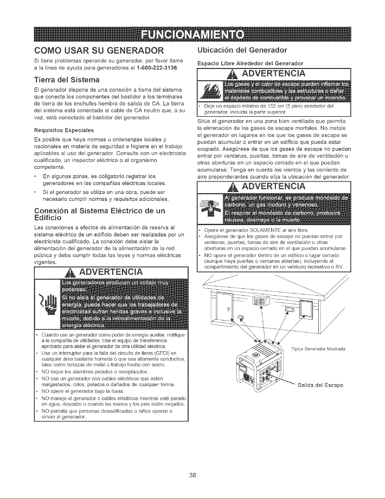
COMO USAR SU GENERADOR
Si tiene problemas operando su generador, por favor Ilame
a la linea de ayuda para generadores a! 1o800o222o3136.
Tierra de_ Sistema
El generador dispone de una conexion a tierra del sistema
que conecta los componentes dei bastidor a los terminales
de tierra de los enchufes hembra de salida de CA. La tierra
del sistema esta conectada al cable de CA neutro que, a su
vez, esta conectado al bastidor del generador.
Requisitos Especiales
Es posible que haya normas u ordenanzas locales y
nacionales en materia de seguridad e higiene en e! traba]o
aplicables al uso del generador. Consulte con un electricista
cualificado, un inspector electrico o el organismo
competente.
En algunas zonas, es obligatorio registrar los
generadores en las compa_ias el6ctricas locales.
S{ el generador se utiliza en una obra, puede set
necesario cumplir normas y requisitos adicionales.
Conexi6n al Sistema EI6ctrico de un
Edificio
Las conexiones a efectos de alimentaci6n de reserva al
sistema el6ctrico de un edificio deben ser realizadas por un
electricista cualificado. La conexi6n debe aislar la
alimentaci6n del generador de la alimentaci6n de la red
pOblica y debe cumplir todas las leyes y normas el6ctricas
vigentes.
ADVERTENCiA
Cuando use un generador como poder de energia auxiliar, notifique
a ta compaFfia de utilidades. Use et equipo de transferencia
aprobado para aistar et generador de otra utilidad et6ctrica.
Use un interruptor para la falla del circuito de tierra (GFCI) en
cualquier area bastante hOmeda o que sea altamente conductiva,
tales como terrazas de metal o trabajo hecho con acero.
NO toque los alambres pelados o receptacutos.
NO use un generador con cables et6ctricos que est6n
malgastados, rotos, petados o da_ados de cuatquier forma.
NO opere et generador bajo la Ituvia.
NO maneje el generador o cables electricos mientras est6 parado
en agua, descatzo o cuando las manos y los pies est6n mojados.
NO permita que personas descalificadas o niSos operen o
sirvan al generador.
Ubicaci6n del Generador
Espacio Libre A[rededor de[ Generador
ADVERTENCJA
Deje un espacio minimo de 152 cm (5 pies) alrededor del
generador, incluida la parte superior.
SitOe el generador en una zona bien ventilada que permita
la eliminaci6n de los gases de escape mortales. No instale
el generador en lugares en los que los gases de escape se
puedan acumular o entrar en un edificio que pueda estar
ocupado. AsegOrese de que los gases de escape no puedan
entrar por ventanas, puertas, tomas de aire de ventilaci6n u
otras aberturas en un espacio cerrado en ei que puedan
acumularse. Tenga en cuenta los vientos y las corriente de
aire preponderantes cuando eli]a la ubicaci6n del generador.
ADVERTENCiA
Opere et generador SOLAMENTE al aire libre.
AsegOrese de que los gases de escape no puedan entrar por
ventanas, puertas, tomas de aire de ventilaci6n u otras
aberturas en un espacio cerrado en el que puedan acumularse.
NO opere et generador dentro de un edificio o lugar cerrado
(aunque haya puertas o ventanas abiertas), incluyendo el
compartimiento del generador en un vehiculo recreativo o RV.
38
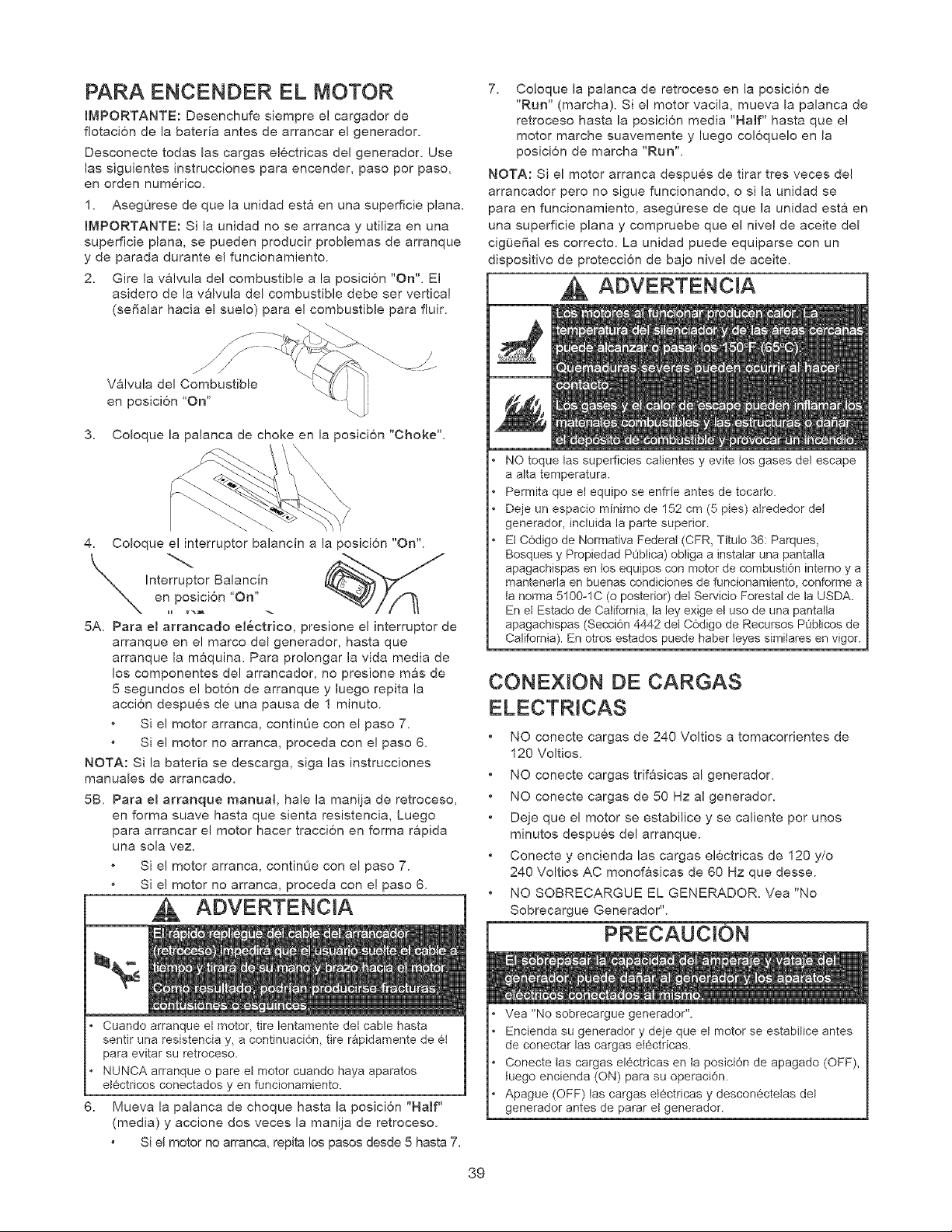
PARA ENCENDER EL MOTOR
IMPORTANTE: Desenchufe siempre el cargador de
flotaci6n de la bateria antes de arrancar el generador.
Desconecte todas las cargas electricas deJ generador. Use
las siguientes instrucciones para encender, paso por paso,
en orden numerico.
1. AsegOrese de que la unidad esta en una superficie plana.
IMPORTANTE: Si la unidad no se arranca y utiliza en una
superficie plana, se pueden producir problemas de arranque
y de parada durante e! funcionamiento.
2. Gire la valvula deJ combustible a la posici6n "On". El
asidero de la valvula del combustible debe set vertical
(se6alar hacia el suelo) para e! combustible para fluir.
V&lvula del Combustible
en posici6n "On"
3. Coloque la palanca de choke en la posici6n "Choke".
4. Coloque el interruptor balancin a la posici6n "On".
Interruptor Balancin
en posici6n 'On"
5A. Para el arrancado eJ@ctrico, presione el interruptor de
arranque en el marco del generador, hasta que
arranque la maquina. Para pro!ongar la vida media de
los componentes de! arrancador, no presione mas de
5 segundos el bot6n de arranque y luego repita la
acci6n despu@s de una pausa de 1 minuto.
Si e! motor arranca, continOe con el paso 7.
Si e! motor no arranca, proceda con e! paso 6.
NOTA: Si la bateda se descarga, siga las instrucciones
manuales de arrancado.
5B. Para el arranque manual hale la manija de retroceso,
en forma suave hasta que sienta resistencia, Luego
para arrancar el motor hacer tracci6n en forma rapida
una soJa vez.
Si e! motor arranca, continOe con el paso 7.
Si e! motor no arranca, proceda con e! paso 6.
ADVERTENCIA
m
7. Co!oque la palanca de retroceso en la posici6n de
"Run" (marcha). Si el motor vacila, mueva la palanca de
retroceso hasta la posicion media "Half" hasta que e!
motor marche suavemente y luego co!6quelo en la
posicion de marcha "Run".
NOTA: Si el motor arranca despues de tirar tres veces del
arrancador pero no sigue funcionando, o si la unidad se
para en funcionamiento, asegOrese de que la unidad esta en
una superficie plana y compruebe que el nive! de aceite del
cigOeBal es correcto. La unidad puede equiparse con un
dispositivo de proteccion de bajo nivel de aceite.
ADVERTENCIA
NO toque las superficies calientes y evite los gases del escape
a alta temperatura.
Permita que el equipo se enfrie antes de tocado.
Deje un espacio minimo de 152 cm (5 pies) alrededor det
generador, incluida la parte superior.
El C6digo de Normativa Federal (CFR, Titulo 36: Parques,
Bosques y Propiedad PObtica) obliga a instalar una pantalla
apagachispas en los equipos con motor de combusti6n interno y a
mantenerla en buenas condiciones de funcionamiento, conforme a
ta norma 5t00-1C (o posterior) det Servicio Forestal de la USDA.
En et Estado de California, la ley exige el uso de una pantatla
apagachispas (Secci6n 4442 del C6digo de Recursos POblicos de
California). En otros estados puede haber teyes similares en vigor.
CONE×tON DE CARGAS
ELECTRICAS
NO conecte cargas de 240 Voltios a tomacorrientes de
120 Voltios.
NO conecte cargas trif&sicas al generador.
NO conecte cargas de 50 Hz al generador.
Deje que el motor se estabilice y se caliente pot unos
minutos despues del arranque.
Conecte y encienda las cargas electricas de 120 y/o
240 Voltios AC monofasicas de 60 Hz que desse.
NO SOBRECARGUE EL GENERADOR. Vea "No
Sobrecargue Generador".
6.
Cuando arranque el motor, tire lentamente del cable hasta
sentir una resistencia y, a continuaci6n, tire rapidamente de et
para evitar su retroceso.
NUNCA arranque o pare eI motor cuando haya aparatos
etectricos conectados yen funcionamiento.
Mueva la palanca de choque hasta la posici6n "Haft"
(media) y accione dos veces la manija de retroceso.
Si el motor no arranca, repita los pasos desde 5 hasta 7.
Vea "No sobrecargue generador".
Encienda su generador y deje que et motor se estabitice antes
de conectar las cargas et6ctricas.
Conecte tas cargas electricas en ta posici6n de apagado (OFF),
tuego encienda (ON) para su operaci6n.
Apague (OFF) tas cargas el6ctricas y desconectelas del
generador antes de parar et generador.
39
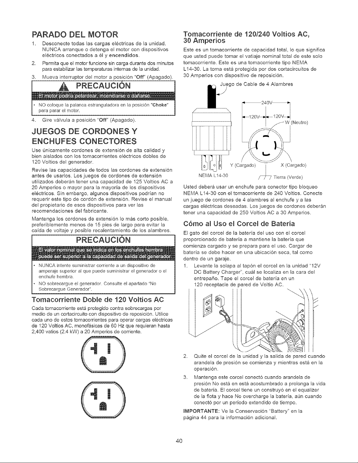
PARADO DEL MOTOR
1. Desconecte todas las cargas el6ctricas de la unidad.
NUNCA arranque o detenga el motor con dispositivos
electricos conectados a 61 y encendidos,
2. Permita que e! motor funcione sin carga durante dos minutos
para estabilizar las temperaturas internas de la unidad.
3. Mueva interruptor del motor a posici6n 'Off" (Apagado).
• NO cotoque la palanca estranguladora en la posici6n "Choke"
para parar el motor.
4. Gire v&lvula a posici6n "Off" (Apagado).
JUEGOS DE CORDONES Y
ENCHUFES CONECTORES
Use L_nicamente cordones de extensi6n de alta calidad y
bien aislados con los tomacordentes electricos dobles de
120 Voltios del generador.
Revise las capacidades de todos las cordones de extensi6n
antes de usar!os. Los juegos de cordones de extensi6n
utilizados deberan tener una capacidad de 125 Voltios AC a
20 Amperios o mayor para la mayoria de los dispositivos
el6ctricos. Sin embargo, algunos dispositivos podrian no
requerir este tipo de cordon de extensi6n. Revise el manual
del propietado de esos dispositivos para ver las
recomendaciones de! fabricante.
Mantenga los cordones de extensi6n Io mas corto posible,
preferibiemente menos de 15 pies de largo para evitar la
caida de voltaje y posible recalentamiento de los alambres.
PRECAUCION
i
• NUNCA intente suministrar corriente a un dispositivo de
amperaje superior at que puede suministrar el generador o el
enchufe hembra.
• NO sobrecargue et generador. Consutte et apartado "No
Sobrecargue Generador".
Tomacorriente Dob_e de 120 Vo_tios AC
Cada tomacorriente esta protegido contra sobrecargas por
medio de un cortacircuito con dispositivo de reposici6n. Utilice
cada uno de estos tomacorrientes para operar cargas el6ctricas
de 120 Voltios AC, monofasicas de 60 Hz que requieran hasta
2,400 vatios (2.4 kW) a 20 Amperios de corriente.
Tomacorriente de 1201240 Vo_tios AC,
30 Amperios
Este es un tomacorriente de capacidad total, Io que significa
que usted puede tomar e! vatiaje nominal total de este solo
tomacordente. Este es una tomacorriente tipo NEMA
L14:30. La toma esta protegida por dos cortacircuitos de
30 Amperios con dispositivo de reposici6n.
_go de Cable de 4 Alambres
(Neutro)
/l_0_L_o _ Y(Cargado) | X(Cargado)
NEMA L14-30 _ Tierra (Verde)
Usted deber& usar un enchufe para conector tipo bloqueo
NEMA L14-30 con el tomacorriente de 240 Voltios. Conecte
un juego de cordones de 4 alambres al enchufe y alas
cargas el6ctricas deseadas. Los juegos de cordones deberan
tener una capacidad de 250 Voltios AC a 30 Amperios.
C6mo a_ Uso e_ Corce_ de Bateria
El gato del corcel de la bateria de! uso con el corcel
proporcionado de bateria a mantiene la bateria que
comienza cargado y se prepara para el uso. Cargar de
bateria se debe hacer en una ubicaci6n seca, tal como
dentro de un garaje.
1. Levante la solapa al tap6n el corce! en la unidad "12V
DC Battery Charger", cual se Iocaliza en la cara de!
entrepafio. Tape el corce! de bateria en un
120 receptacle de pared de Voltio AC.
y
2. Quite el corcel de la unidad y la salida de pared cuando
arandela de presion se comienza y mientras est& en la
operaci6n.
3. Mantenga este corcel conect6 cuando arandela de
presion No esta en esta acostumbrado a prolonga la vida
de bateria. E! corcel tiene un construy6 en el equalizer
de la flota y hace No overcharge la bateria, aOn cuando
conect6 por un periodo extend!do de tiempo.
IMPORTANTE: Ve la Conservaci6n "Battery" en la
p&gina 44 para la informaci6n adicional.
4O
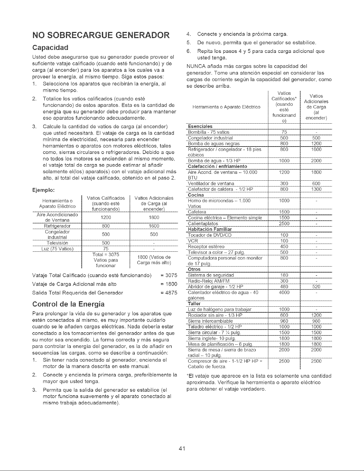
NO SOBRECARGUE GENERADOR
Capacidad
Usted debe asegurarse que su generador puede proveer el
suficiente vataje calificado (cuando este funcionando) y de
carga (al encender) para los aparatos a los cuales va a
proveer la energia, al mismo tiempo. Siga estos pasos:
1. Seleccione los aparatos que recibir&n la energia, al
mismo tiempo.
2. Totalice los vatios calificados (cuando este
funcionando) de estos aparatos. Esta es la cantidad de
energia que su generador debe producir para mantener
eso aparatos funcionando adecuadamente.
3. Calcule la cantidad de vatios de carga (al encender)
que usted necesitara. El vataje de carga es la cantidad
minima de electricidad, necesaria para encender
herramientas o aparatos con motores electricos, tales
como, sierras circulares o refrigeradores, Debido a que
no todos los motores se encienden al mismo momento,
e! vataje total de carga se puede estimar al affadir
solamente el(los) aparato(s) con e! vataje adicional mas
alto, al total del vataje calificado, obtenido en el paso 2.
Ejemplo:
Herramienta o
Aparato EI6ctrico
Aire Acondicionado
de Ventana
Refriqerador
Congelador
industrial
Tetevisi6n
Luz (75 Vatios)
Vatios Catificados
(cuando este
funcionando)
1200
8OO
5OO
50O
75
Total = 3075
Vatios para
funcionar
Vatios Adicionales
de Carga (al
encender)
1800
1600
5OO
1800 (Vatios de
Carga mas alto)
Vataje Total Calificado (cuando este funcionando) = 3075
Vataje de Carga Adiciona! mas alto = 1800
Salida Total Requerida de! Generador = 4875
Control de [a Energia
Para prolongar la vida de su generador y los aparatos que
esten conectados al mismo, es muy importante cuidarlo
cuando se le affaden cargas electricas. Nada deberia estar
conectado a los tomacorrientes de! generador antes de que
su motor sea encendido. La forma correcta y mas segura
para controlar la energia del generador, es la de affadir en
secuencias las cargas, como se describe a continuaci6n:
1. Sin tener nada conectado al generador, encienda el
motor de la manera descrita en este manual.
2. Conecte y encienda la primera carga, preferiblemente la
mayor que usted tenga.
3. Permita que la salida del generador se estabilice (el
motor funciona suavemente y el aparato conectado al
mismo trabaja adecuadamente).
4. Conecte y encienda la proxima carga.
5. De nuevo, permita que el generador se estabilice.
6. Repita los pasos 4 y 5 para cada carga adicional que
usted tenga.
NUNCA affada mas cargas sobre la capacidad del
generador. Tome una atenci6n especial en considerar las
cargas de corriente segOn la capacidad del generador, como
se describe arriba.
Herramienta o Aparato Electrico
Esenciales
Bombilta - 75 vatios
Congelador industrial
Bomba de aguas n_ras
Refrigerador / congelador - 18 pies
cObicos
Bomba de agua - 1/3 HP
Ca_efacci6n t enfriamiento
Aire Acond. de ventana - 10.000
BTU
Ventflador de ventana
Calefactor de caldera - 1/2 HP
Cocina
Homo de microondas - 1.000
Vatios
Cafetera
Cocina et6ctrica - Elemento sirnple
Calientaplatos
Habitaci6n Familiar
Tocader de DVD/CD
VCR
Receptor estereo
Televisor a color - 27 pulg.
Computadora personal con monitor
de 17 put9.
Otros
Sistema de s_uridad
Radio-Reloj AM/FM
Abridor de garaje - 1/2 HP
Calentador el6ctrico de agua - 40
galones
Taller
Luz de ha_6oeno Dara trabaiar
Rociador sin aire - 1/3 HP
Sierra intercambiabte
Tatadro el@ctrico - 1/2 HP
1
Sierra circular - 7 Z pulp.
Sierra ingtete- 10 pulg.
Mesa de pJanificaci6n - 6 uE_g\
Sierra de mesa / sierra de brazo
radial- 10 pulg.
Compresor de aire - 1-1/2 HP HP =
Caballo de fuerza.
Vatios
Vatios
Catificados*
Adicionales
(cuando de Carga
est6
funcionand (at
o) encender)
75
500 500
800 1200
800 1600
1000 2000
1200 1800
300 600
800 1300
1000
1500
1500
2500
100
100
45O
5O0
8OO
180
3OO
480 520
4000
1000
600 1200
960 960
1000 1000
1500 1500
1800 1800
1800 1800
2000 2000
2500 2500
*El vataje que aparece en la lista es solamente una cantidad
aproximada. Vefifique la herramienta o aparato electrico
para obtener ei vataje verdadero.
41
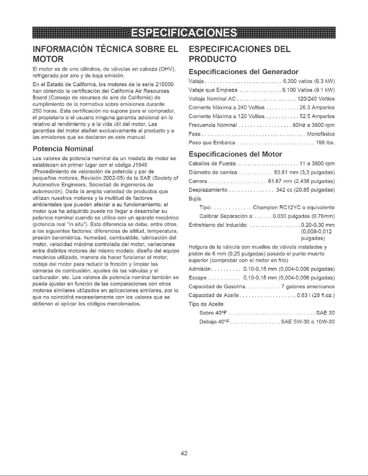
INFORMACION Tg:CNICA SOBRE EL
MOTOR
El motor es de uno cilindros, de valvulas en cabeza (OHV),
refrigerado por aire y de baja emisi6n.
En e! Estado de California, los motores de la serie 210000
hart obtenido la certificacion del California Air Resources
Board (Consejo de recursos de aire de California) de
cumplimiento de la normativa sobre emisiones durante
250 horas. Esta certificaci6n no supone para el comprador,
el propietario o el usuario ninguna garanfia adicional en Io
relativo al rendimiento y a la vida Oti! del motor. Las
garantias del motor atafien exclusivamente al producto y a
las emisiones que se declaran en este manual.
Potencia Nominal
Los valores de potencia nominal de un modelo de motor se
establecen en primer lugar con el codigo J1940
(Procedimiento de valoraci6n de potencia y par de
pequet'ios motores, Revision 2002-05) de la SAE (Society of
Automotive Engineers, Sociedad de ingenieros de
automoci6n). Dada la amplia variedad de productos que
utilizan nuestros motores y la multitud de factores
ambientales que pueden afectar a su funcionamiento, el
motor que ha adquiddo puede no Ilegar a desarro!lar su
potencia nominal cuando se utilice con un aparato mecanico
(potencia real "in situ"). Esta diferencia se debe, entre otros,
a los siguientes factores: diferencias de altitud, temperatura,
presi6n barometrica, humedad, combustible, lubricaci6n del
motor, ve!ocidad maxima controlada del motor, variaciones
entre distintos motores del mismo modelo, disefio del equipo
mecanico utilizado, manera de hacer funcionar el motor,
rodaje de! motor para reducir la fricci6n y limpiar las
camaras de combusti6n, ajustes de las valvulas y el
carburador, etc. Los valores de potencia nominal tambien se
puede ajustar en funci6n de las comparaciones con otros
motores similares utilizados en aplicaciones similares, pot Io
que no coincidira necesariamente con los valores que se
obtienen al aplicar los codigos mencionados.
ESPECIFtCACtONES DEL
PRODUCTO
Especificaciones del Generador
Vataje .......................... 6,300 vatios (6.3 kW)
Vataje que Empieza .............. 9,100 Vatios (9.1 kW)
Voltaje Nominal AC .................... 120/240 Voltios
Corriente Maxima a 240 Voltios ........... 26.3 Amperios
Corriente Maxima a 120 Voltios ........... 52.5 Amperios
Frecuencia Nominal .................. 60Hz a 3600 rpm
Fase ................................... Monofasica
Peso que Embarca .......................... 198 Ibs.
Especificaciones del Motor
Cabal!os de Fuerza ..................... 11 a 3600 rpm
Diametro de camisa ........... 83.81 mm (3,3 pulgadas)
Carrera ................... 61.67 mm (2,438 pulgadas)
Desplazamiento ............... 342 cc (20,85 pulgadas)
Bujia
Tipo: ............. Champion RC12YC o equivalente
Calibrar Separacion a: ...... 0.030 pulgadas (0.76mm)
Entrehierro de! inducido: ................. 0,20°0,30 mm
(0,008-0,012
pulgadas)
Holgura de la valvula con mue!les de valvula instalados y
piston de 6 mm (0,25 pulgadas) pasado e! punto muerto
superior (comprobar con el motor en fr[o)
Admisi6n .......... 0,10-0,15 mm (0,004-0,006 pulgadas)
Escape ........... 0,10-0,15 mm (0,004-0,006 pulgadas)
Capacidad de Gasolina ............ 7 galones americanos
Capacidad de Aceite ................... 0.83 I (28 fl.oz.)
Tipo de Aceite
Sobre 40°F ............................. SAE 30
Debajo 40°F ................. SAE 5W-30 o 10W-30
42
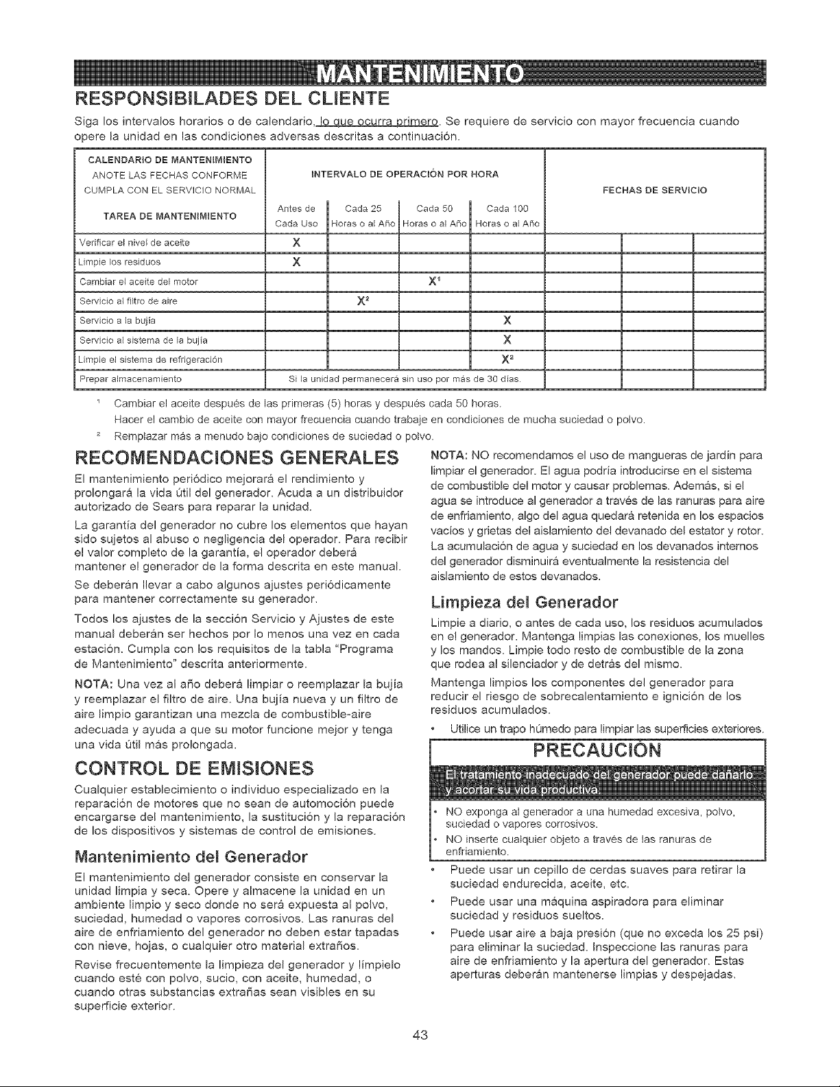
RESPONSIBILADES DEL CLIENTE
Siga los intervalos horarios o de calendario,_ue ocurra primero. Se requiere de servicio con mayor frecuencia cuando
opere la unidad en las condiciones adversas descritas a continuaci6n.
CALENDARIO DE MANTENIMIENTO
ANOTE LAS FECHAS CONFORME
CUMPLA CON EL SERVICIO NORMAL
TAREA DE MANTENIM_ENTO
Verificar el nivel de aceite
Limpie Eosresiduos
Cambiar el aceite del motor
Servicio al fHtro de aire
Servicio a la bujia
Servicio al sistema de la bujia
Limpie el sistema de refrigeraci6n
Prepar almacenamiento
INTERVALO DE OPERACION POR HORA
Antes de
Cada Uso
X
X
Cada 25 Cada 50
Horas o a Afio Horas o a Afio
X _
X 2
Cada 100
Horas o al Afio
x
x
x 2
Si la unidad permanecera sin uso por mas de 30 dias
FECHAS DE SERVIC$O
Cambiar el aceite despu6s de las primeras (5) horas y despues cada 50 horas.
Hacer el cambio de aceite con mayor frecuencia cuando trabaje en condiciones de mucha suciedad o potvo.
Remptazar mas a menudo bajo condiciones de suciedad o potvo.
RECOMENDACIONES GENERALES NOTA: NO recomendamos el uso de mangueras de jardin para
El mantenimiento periodico mejorara el rendimiento y
prolongara la vida Otil del generador. Acuda a un distribuidor
autorizado de Sears para reparar la unidad.
La garantia del generador no cubre los elementos que hayan
sido sujetos al abuso o negligencia del operador. Para recibir
e! valor completo de la garantia, el operador debera
mantener e! generador de la forma descrita en este manual.
Se deberan Ilevar a cabo algunos ajustes peri6dicamente
para mantener correctamente su generador.
Todos los ajustes de la seccion Servicio y Ajustes de este
manual deberan ser hechos por Io menos una vez en cada
estaci6n. Cumpla con los requisitos de la tabla "Programa
de Mantenimiento" descrita anteriormente.
NOTA: Una vez al aSo debera limpiar o reemplazar la bujia
y reemplazar el filtro de aire. Una bujia nueva y un filtro de
aire limpio garantizan una mezcla de combustible-aire
adecuada y ayuda a que su motor funcione mejor y tenga
una vida Otil mas pro!ongada.
CONTROL DE EMlSlONES
Cualquier establecimiento o individuo especializado en la
reparacion de motores que no sean de automoci6n puede
encargarse del mantenimiento, la sustituci6n y la reparaci6n
de los dispositivos y sistemas de control de emisiones.
Mantenimiento del Generador
El mantenimiento del generador consiste en conservar la
unidad limpia y seca. Opere y almacene la unidad en un
ambiente limpio y seco donde no sera expuesta al polvo,
suciedad, humedad o vapores corrosivos. Las ranuras del
aire de enfriamiento del generador no deben estar tapadas
con nieve, hojas, o cualquier otto material extrafios.
Revise frecuentemente la limpieza del generador y limpielo
cuando este con polvo, sucio, con aceite, humedad, o
cuando otras substancias extra,as sean visibies en su
superficie exterior.
limpiar el generador. El agua podria introducirse en el sistema
de combustible del motor y causar problemas. Ademas, si el
agua se introduce al generador a traves de las ranuras para aire
de enfriamiento, algo del agua quedara retenida en los espacios
vacios y grietas del aislamiento de! devanado del estator y rotor.
La acumulacion de agua y suciedad en los devanados intemos
del generador disminuira eventualmente la resistencia de!
aislamiento de estos devanados.
Limpieza del Generador
Limpie a diario, o antes de cada uso, los residuos acumulados
en e! generador. Mantenga limpias las conexiones, los muelles
y los mandos. Limpie todo resto de combustible de la zona
que rodea a! silenciador y de detras del mismo.
Mantenga limpios los componentes del generador para
reducir el riesgo de sobrecalentamiento e ignici6n de los
residuos acumulados.
Utilice un trapo hOmedo para limpiar las superficies exteriores.
NO exponga al generador a una humedad excesiva, potvo,
suciedad o vapores corrosivos.
NO inserte cualquier objeto a trav6s de tas ranuras de
enfriamiento.
Puede usar un cepillo de cerdas suaves para retirar la
suciedad endurecida, aceite, etc.
Puede usar una maquina aspiradora para eliminar
suciedad y residuos sueltos.
Puede usar aire a baja presi6n (que no exceda los 25 psi)
para eliminar la suciedad. Inspeccione las ranuras para
aire de enfriamiento y la apertura del generador. Estas
aperturas deberan mantenerse limpias y despejadas.
43
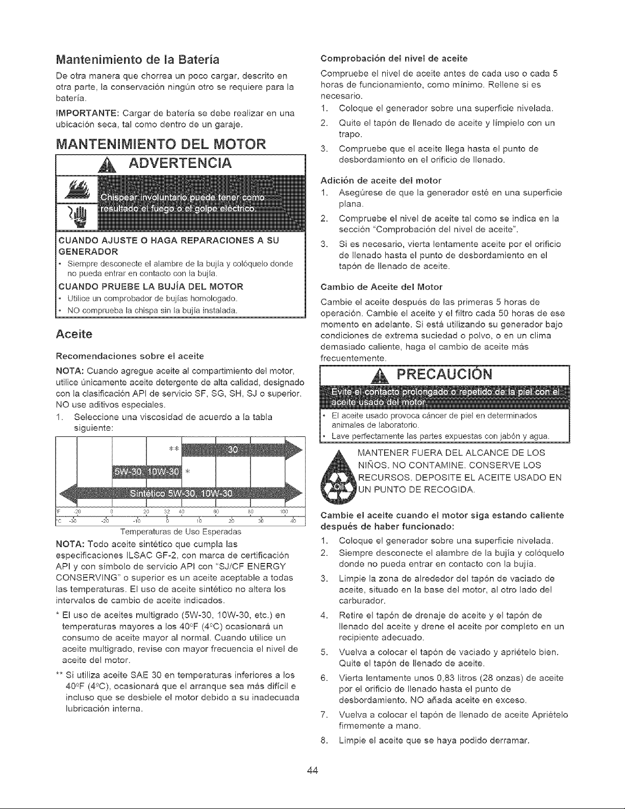
Mantenimiento de [a Bater[a
De otra manera que chorrea un poco cargar, descrito en
otra parte, la conservaci6n ningOn otro se requiere para la
bateda.
[r,/_PORTANTE: Cargar de bateria se debe realizar en una
ubicacion seca, tal como dentro de un garaje.
MANTEN[M[ENTO DEL MOTOR
CUANDO AJUSTE O HAGA REPARACIONES A SU
GENERADOR
Siempre desconecte el aiambre de la buj[a y cot6quelo donde
no pueda entrar en contacto con ta bujia.
CUANDO PRUEBE LA BUJ[A DEL MOTOR
Utilice un comprobador de buj[as homologado.
NO comprueba la chispa sin ta bujia instalada.
Aceite
Recomendaciones sobre e[ aceite
NOTA: Cuando agregue aceite al compartimiento de! motor,
utilice 0nicamente aceite detergente de alta calidad, designado
con la clasificaci6n API de servicio SF, SG, SH, SJ o superior.
NO use aditivos especiales.
1. Seleccione una viscosidad de acuerdo a la tabla
siguiente:
Temperaturas de Use Esperadas
NOTA: Todo aceite sintetico que cumpla las
especificaciones ILSAC GF-2, con marca de certificaci6n
API y con simbolo de servicio API con 'SJ/CF ENERGY
CONSERVING" o superior es un aceite aceptable a todas
las temperaturas. El uso de aceite sintetico no altera los
intervaIos de cambio de aceite indicados.
* El uso de aceites multigrado (5W-30, 10W°30, etc.) en
temperaturas mayores a los 40°F (4°C) ocasionara un
consumo de aceite mayor al normal. Cuando utilice un
aceite multigrado, revise con mayor frecuencia e[ nivel de
aceite de[ motor.
** Si utiliza aceite SAE 30 en temperaturas inferiores a los
40°F (4°C), ocasionara que el arranque sea mas dificil e
incluso que se desbiele el motor debido a su inadecuada
lubricaci6n interna.
Comprobaci6n de[ hive[ de aceite
Compruebe el nive! de aceite antes de cada uso o cada 5
horas de funcionamiento, como minimo. Rellene si es
neoesario.
1. Coloque el generador sobre una superficie nivelada.
2. Quite ei tapon de Ilenado de aceite y limpie!o con un
trapo.
3. Compruebe que el aceite Ilega hasta e! punto de
desbordamiento en e[ orificio de Ilenado.
Adici6n de aceite de[ motor
1. AsegOrese de que la generador este en una superficie
plana.
2. Compruebe el nivel de aceite tal como se indica en la
seccion "Comprobacion del nivel de aceite".
3. Si es necesario, vierta lentamente aceite por el orificio
de Ilenado hasta el punto de desbordamiento en el
tapon de Ilenado de aceite.
Cambio de Aceite de[ Motor
Cambie el aceite despues de las primeras 5 horas de
operaci6n. Cambie e! aceite y e! filtro cada 50 horas de ese
momento en adelante. Si est& utilizando su generador bajo
condiciones de extrema suciedad o polvo, o en un clima
demasiado caliente, haga e[ cambio de aceite mas
frecuentemente.
PRECAUCI6N
El aceite usado provoca cancer de piel en determinados
animates de taboratorio.
Lave perfectamente tas pares expuestas con jab6n y agua.
MANTENER FUERA DEL ALCANCE DE LOS
NI[_OS. NO CONTAMINE. CONSERVE LOS
RECURSOS. DEPOSITE EL ACEITE USADO EN
UN PUNTO DE RECOGIDA.
Cambie e[ aceite cuando el motor siga estando ca[iente
despu_s de haber funcionado:
1. Coloque e! generador sobre una superficie nivelada.
2. Siempre desconecte el alambre de la bujia y co!6quelo
donde no pueda entrar en contacto con la bujia.
3. Limpie la zona de alrededor de! tapon de vaciado de
aceite, situado en la base de[ motor, a! otro lado de!
carburador.
4. Retire el tapon de drenaje de aceite y el tapon de
Ilenado del aceite y drene e! aceite por completo en un
recipiente adecuado.
5. Vue]va a colocar el tapon de vaciado y apriete!o bien.
Quite e! tapon de Ilenado de aceite.
6. Vierta lentamente unos 0,83 litros (28 onzas) de aceite
por el orificio de Ilenado hasta el punto de
desbordamiento. NO affada aceite en exceso.
7. Vuelva a colocar el tapon de Ilenado de aceite Aprietelo
firmemente a mano.
8. Limpie el aceite que se haya podido derramar.
44
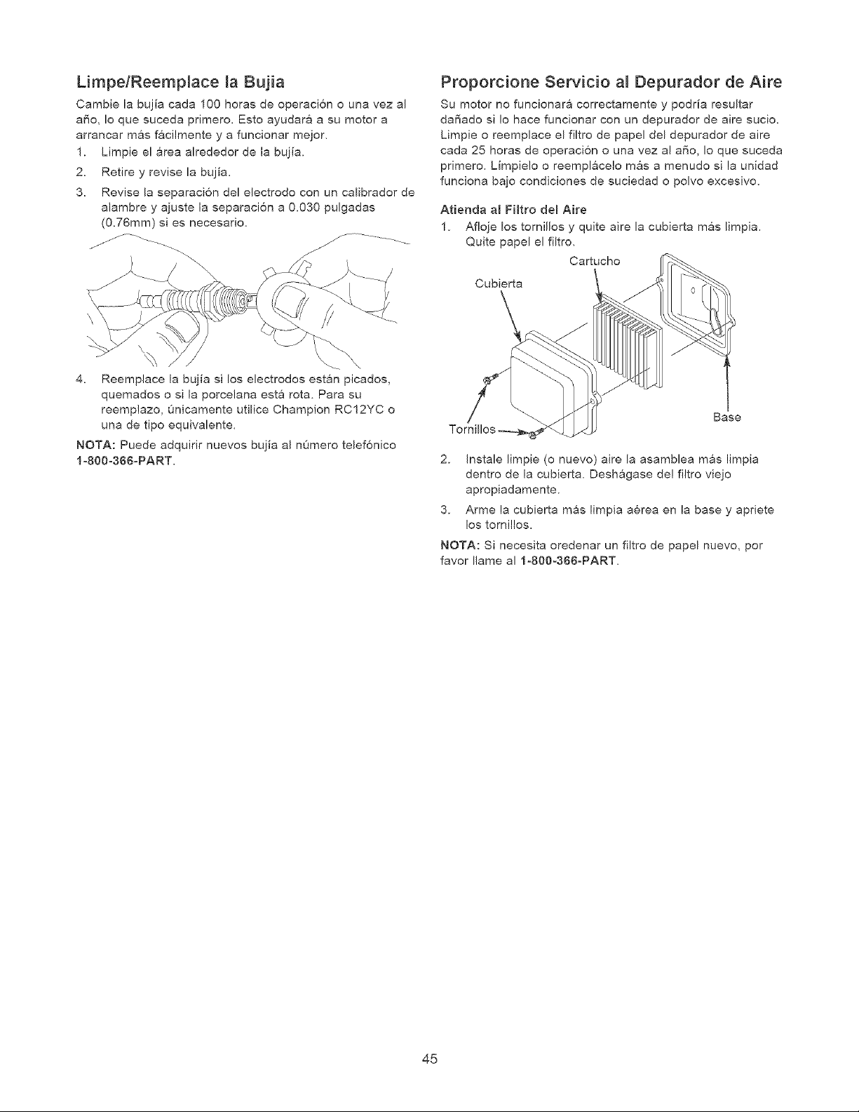
LimpelReemp_ace _a Bujia
Cambie la bujia cada 100 horas de operacion o una vez al
also, Io que suceda primero. Esto ayudara a su motor a
arrancar mas facilmente y a funcionar mejor.
1. Limpie el area alrededor de la bujia.
2. Retire y revise la bujia.
3. Revise la separaci6n del electrodo con un calibrador de
alambre y ajuste la separacion a 0.030 pulgadas
(0.76ram) si es necesario.
Proporcione Servicio a_ Depurador de Aire
Su motor no funcionara correctamente y podria resultar
da_ado si !o hace funcionar con un depurador de aire sucio.
Limpie o reemplace el filtro de papel del depurador de aire
cada 25 horas de operaci6n o una vez al a_o, Io que suceda
primero. Limpie!o o reemplacelo mas a menudo si la unidad
funciona bajo condiciones de suciedad o polvo excesivo.
Atienda a[ Fi[tro de[ Aire
1. Afloje los tornillos y quite aire la cubierta mas limpia.
Quite papel el filtro.
Cartucho
Cubierta
4. Reemplace la bujia si los electrodos estan picados,
quemados o si la porcelana esta rota, Para su
reemplazo, 0nicamente utilice Champion RC12YC o
una de tipo equivalente.
NOTA: Puede adquirir nuevos bujia al n0mero telef6nico
loS00o366opART.
Base
2. Instale limpie (o nuevo) aire la asamblea mas limpia
dentro de la cubierta. Deshagase de! filtro viejo
apropiadamente.
3. Arme la cubierta mas limpia aerea en la base y apriete
los tornillos.
NOTA: Si necesita oredenar un filtro de papel nuevo, pot
favor Ilame al 1o800o366oPART.
45
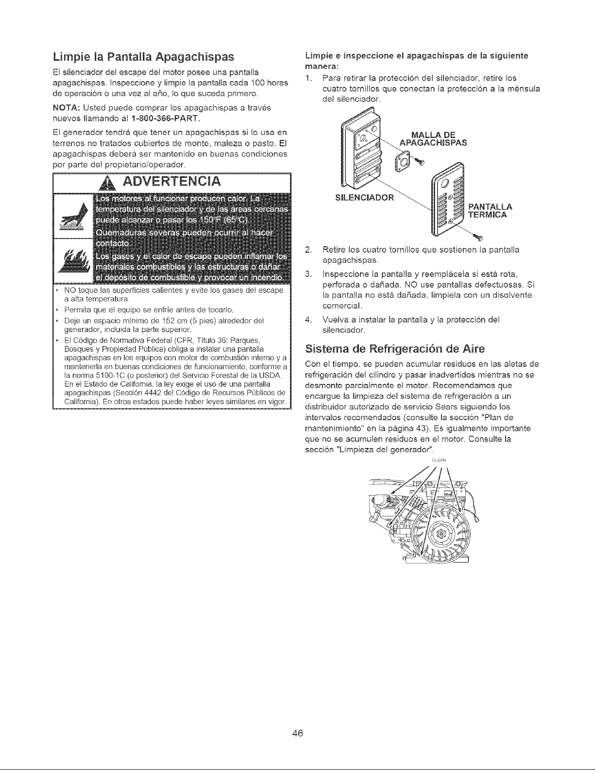
Limpie _a PantaHa Apagachispas
El silenciador del escape de! motor posee una pantalla
apagachispas. Inspeccione y limpie la pantalla cada 100 horas
de operacion o una vez al a_o, Io que suceda primero.
NOTA: Usted puede comprar los apagachispas a traves
nuevos Ilamando al 1o800o366oPART.
El generador ten@& que tener un apagachispas si Io usa en
terrenos no tratados cubiertos de monte, maleza o pasto. El
apagachispas deber& ser mantenido en buenas condiciones
por parte de! propietario/operador.
ADVERTENCiA
NO toque tas superficies calientes y evite los gases det escape
a alta temperatura.
Permita queet equipo se enfde antes de tocarlo.
Deje un espacio minimo de 152 cm (5 pies) alrededor del
generador, inctuida la parte superior.
El C6digo de Normativa Federal (CFR, Titulo 36: Parques,
Bosques y Propiedad PQblica) obtiga a instatar una pantalta
apagachispas en los equipos con motor de combusti6n intemo y a
mantenerla en buenas condJciones de funcionamiento, conforme a
la norma 5100-1C (o posterior) del Servicio Forestal de la USDA.
En el Estado de California, ta tey exige et uso de una pantalta
apagachispas (Seccidn 4442 dei C6digo de Recursos PQblicos de
California). En otros estados puede haber leyes similares en vigor.
Limpie e inspeccione e[ apagachispas de Ja siguiente
manera:
1. Para retirar la protecci6n del silenciador, retire los
cuatro tornillos que conectan la protecci6n a la m6nsula
del silenciador.
__G, ANALLA DE
CHJSPAS
S_ PANTALLA
RNJCA
2. Retire los cuatro tornillos que sostienen la pantalla
apagachispas.
3. Inspeccione la panta!la y reempl&cela si esta rota,
perforada o da_ada. NO use pantallas defectuosas. Si
la pantalla no esta dal_ada, limpiela con un disolvente
comerciak
4. Vuelva a instalar la pantalla y la proteccion de!
silenciador.
Sistema de Refrigeraci6n de Aire
Con el tiempo, se pueden acumular residuos en las aletas de
refrigeraci6n del cilindro y pasar inadvertidos mientras no se
desmonte parcialmente el motor. Recomendamos que
encargue la limpieza de! sistema de refrigeraci6n a un
distribuidor autorizado de servicio Sears siguiendo los
intervalos recomendados (consulte la seccion "Plan de
mantenimiento" en la pagina 43). Es igualmente importante
que no se acumulen residuos en e! motor. Consulte la
secci6n "Limpieza de! generador".
CLAN
46
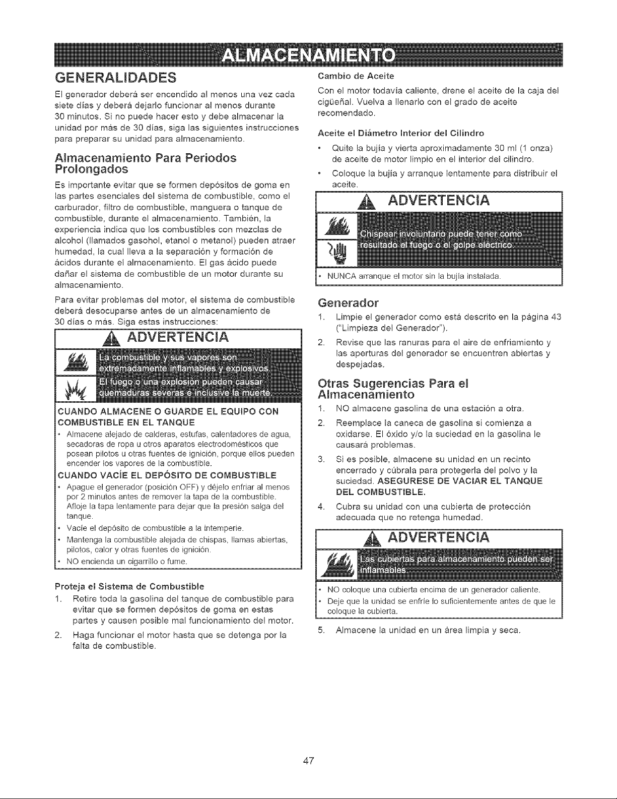
GENERALIDADES
El generador deber& ser encendido al menos una vez cada
siete dias y debera dejarlo funcionar al menos durante
30 minutos. Si no puede hacer esto y debe almacenar la
unidad pot mas de 30 dias, siga las siguientes instrucciones
para preparar su unidad para almacenamiento.
Atmacenamiento Para Periodos
Prolongados
Es importante evitar que se formen depositos de goma en
las partes esenciales del sistema de combustible, como e!
carburador, filtro de combustible, manguera o tanque de
combustible, durante el aJmacenamiento. Tambien, la
experiencia indica que los combustibles con mezclas de
alcohol (llamados gasoho!, etanol o metano!) pueden atraer
humedad, la cual Ileva a la separacion y formacion de
acidos durante el almacenamiento. El gas acido puede
da_ar el sistema de combustible de un motor durante su
almacenamiento.
Para evitar problemas del motor, el sistema de combustible
debera desocuparse antes de un almacenamiento de
30 dias o mas. Siga estas instrucciones:
ADVERTENCIA
CUANDO ALMACENE O GUARDE EL EQUJPO CON
COMBUSTIBLE EN EL TANQUE
AImacene atejado de calderas, estufas, calentadores de agua,
secadoras de ropa u otros aparatos etectrodom6sticos que
posean pilotos u otras fuentes de ignici6n, porque eltos pueden
encender tos vapores de la combustible.
CUANDO VACiE EL DEP6SITO DE COMBUSTIBLE
Apague el generador (posici0n OFF) y d6jeto enfriar al menos
por 2 minutos antes de remover ta tapa de ta combustible.
Afloje la tapa lentamente para dejar que la presi6n salga del
tanque.
Vacie el dep6sito de combustible a la intemperie.
Mantenga la combustible alejada de chispas, llamas abiertas,
pilotos, calory otras fuentes de ignici6n.
NO encienda un cigarritto o fume.
Proteja el Sistema de Combustible
1. Retire toda la gasolina del tanque de combustible para
evitar que se formen dep6sitos de goma en estas
partes y causen posible real funcionamiento de! motor.
2. Haga funcionar e! motor hasta que se detenga por la
falta de combustible.
Cambio de Aceite
Con el motor todavia caliente, drene e! aceite de la caja del
cig_eSaJ. Vuelva a !lenarlo con el grado de aceite
recomendado.
Aceite el Di_metro Interior del CHindro
Quite la bujia y vierta aproximadamente 30 ml (1 onza)
de aceite de motor limpio en el interior de! cilindro.
Co!oque la bujia y arranque lentamente para distribuir e!
aceite.
Je el motor sin la bu Ja instalada.
Generador
1. Limpie el generador como esta descrito en la p&gina 43
("Limpieza deJ Generador').
2. Revise que las ranuras para e! aire de enfriamiento y
las aperturas del generador se encuentren abiertas y
despejadas.
Otras Sugerencias Para el
A_macenamiento
1. NO almacene gasolina de una estaci6n a otra.
2. Reemplace la caneca de gasoJina si comienza a
oxidarse. El oxido y/o la suciedad en la gasolina le
causara problemas.
3. Si es posible, almacene su unidad en un recinto
encerrado y cObrala para protegerla del polvo y la
suciedad. ASEGURESE DE VACIAR EL TANQUE
DEL COMBUST{BLE.
4. Cubra su unidad con una cubierta de protecci6n
adecuada que no retenga humedad.
ADVERTENCIA
NO coloque una cubierta encima de un generador caliente.
Deje que la unidad se enfrie to suficientemente antes de que le
coloque ta cubierta.
5. AImacene la unidad en un area limpia y seca.
47
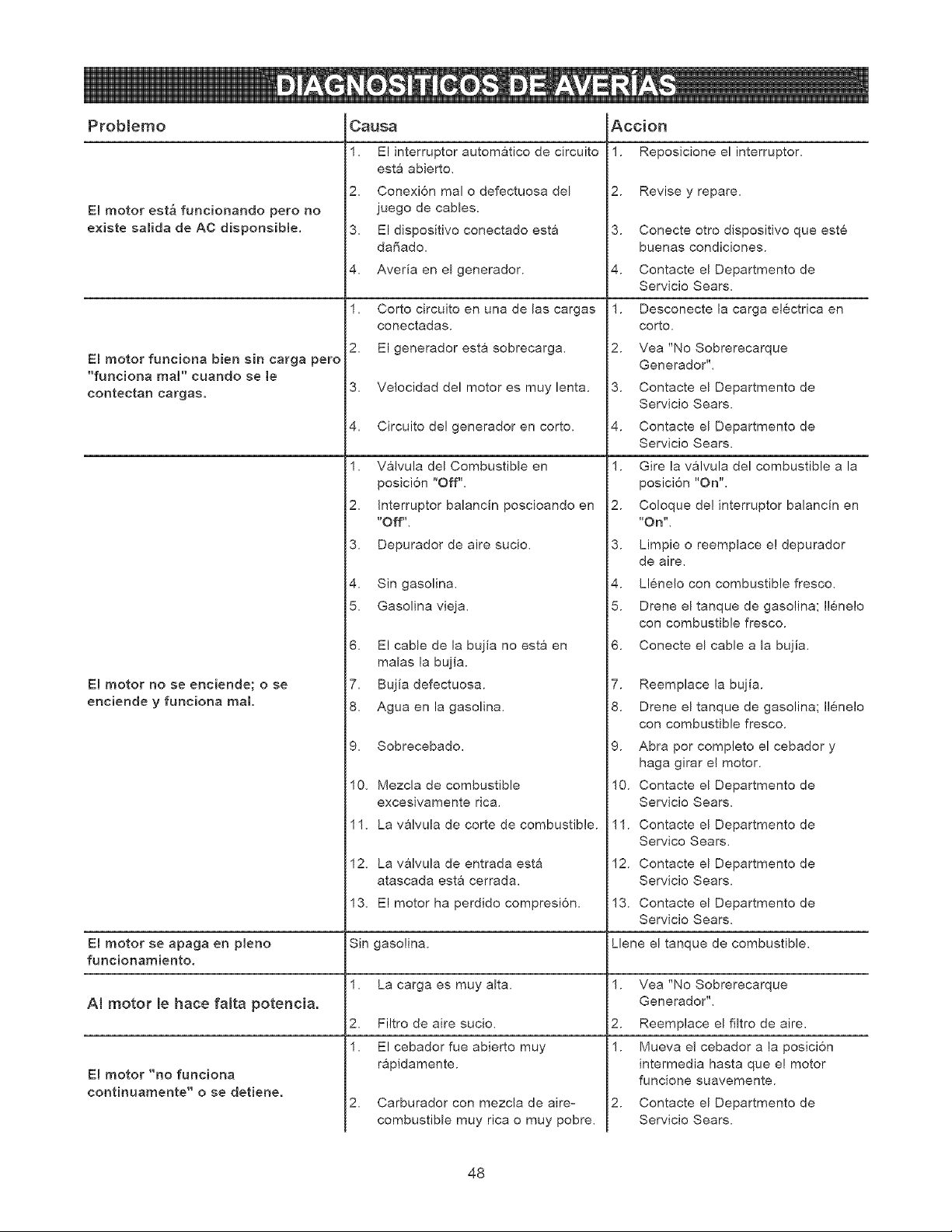
Problemo
E! motor est_ funcionando pero no
e×iste salida de A¢ disponsible.
El motor funciona bien sin carga pero
"funciona maF' cuando se le
contectan eargas.
Causa
1, El interruptor automatico de circuito
esta abierto,
2, Conexi6n real o defectuosa del
juego de cables.
3, El dispositivo conectado esta
da_ado,
4, Averia en el generador.
1, Corto circuito en una de las cargas
conectadas.
2, El generador esta sobrecarga,
3, Ve!ocidad del motor es muy lenta.
4, Circuito de! generador en corto.
1, Valvula del Combustible en
posici6n "Off".
2, Interruptor balancin poscioando en
Accion
1. Reposicione el interruptor,
2. Revise y repare,
3. Conecte otro dispositivo que este
buenas condiciones.
4. Contacte el Departmento de
Servicio Sears.
1. Desconecte la carga electrica en
corto,
2. Vea "No Sobrerecarque
Generador'L
3. Contacte el Departmento de
Servicio Sears.
4. Contacte el Departmento de
Servicio Sears.
1. Gire la valvula del combustible a la
posicion "On",
2. Coloque de! interruptor balancin en
E! motor no se enciende; o se
enciende y funciona real
"Off",
3, Depurador de aire sucio,
4, Sin gasolina,
5, Gasolina vieja,
6, El cable de la bujia no esta en
malas la bujia.
7, Bujia defectuosa.
8, Agua en la gasolina,
9, Sobrecebado,
10, Mezcla de combustible
excesivamente rica,
3.
4.
5.
6.
7.
8.
9.
10.
"On",
Limpie o reemplace el depurador
de aire,
Llene!o con combustible fresco,
Drene el tanque de gasolina; Ilenelo
con combustible fresco.
Conecte el cable a la bujia,
Reemplace la bujia.
Drene el tanque de gasolina; Ilenelo
con combustible fresco.
Abra por completo el cebador
haga girar e! motor.
Contacte el Departmento de
Servicio Sears.
13_
E[ motor se apaga en p[eno Sin Llene el tanque de combustible,
funcionamiento.
1, 1. Vea "No Sobrerecarque
AI motor le hace fatta potencia. Generador'L
2, 2. Reemplace el filtro de aire,
1,
I:Imotor "no funciona
continuamente" o se detiene.
11, La valvula de corte de combustible.
12, La valvula de entrada esta
atascada esta cerrada,
El motor ha perdido compresion.
gasolina.
La carga es muy alta.
Filtro de aire sucio,
El cebador fue abierto muy
rapidamente.
2, Carburador con mezcla de aire=
combustible muy rica o muy pobre,
1 1. Contacte el Departmento de
Servico Sears,
12. Contacte el Departmento de
Servicio Sears.
13. Contacte el Departmento de
Servicio Sears.
1.
2.
Mueva e! cebador a la posicion
intermedia hasta que el motor
funcione suavemente.
Contacte el Departmento de
Servicio Sears.
48

49
Sears, Roebuck and Co., U.S.A. (Sears), California Air Resources Board (Consejo de Recursos sobre e! Aire de
California, CARB, por sus sigJas en ingles) y United States Environmental Protection Agency (Agencia de Protecci6n
Ambienta[ de EE.UU., EPA, pot sus sig[as en ingles).
Declaraci6n de garantia del sistema de control de ernisiones
(derechos y obligaciones del propietado para Ja garantia contra defectos)
California Air Resources Board (CARB), U.S. EPA y Sears le explican a
continuaci6n la garanga del sistema de control de emisiones de su
peque_o motor para m_quinas de seP¢icio (SORE, Small Offroad Engine).
En California, los mode[os de pequeffos motores para mSquinas de
servicio a partir de[ afro 2006 deben estar dise_ados, fabricados y
equipados conforme a los exigentes est_ndares de lucha contra ta
contaminaci6n del Estado.
En otras regiones de Estados Unidos, los nuevos motores para
interiores de ignici6n por chispa certificados para modelos afro 1997 y
posteriores deben cumplir con normas similares establecidas pot la EPA
de EE.UU. Sears debe garantizar el sistema de control de emisiones de
su motor para los pedodos indicados a continuaci6n, siempre y cuando
no se haya abusado, descuidado o dado mantenimiento incorrecto aJ
motor pequeffo para exteriores
Su sistema de control de emisionas incluye piezas como et carburador_ el
filtro de aire, el sistema de arranque, el tubo de combustibJe_ el silenciador
y el convertidor catalitico. Tambi6n puede incluir conectores y otros
conjuntos reJacionados con las emisiones.
Cuando exista una condici6n que pueda ser cubierta por la garant[a,
Sears reparar_ el motor pequeF_o para exteriores sin costo aiguno,
inciuyendo el diagndstico, las partes de repuesto y la mano de obra.
Cobertura de la garantia de Sears, Roebuck and Co, contra
defectos en el controJ de emisiones
Los peque_os motores para maquinas de servicio estSn garantizados
contra defectos de las piezas de control de emisiones durante un periodo
de dos afios, conforme a [as siguientes disposiciones. Si cualquier pieza del
motor con cobertura es defectuosa, ser_ reparada o sustituida por Sears
Responsabilidades del propietario para la garantia
Como propietado del motor peque_o para exteriores, usted es
responsabJe de realizar [as actividades de mantenimiento requeridas que
se indican en tnstrucciones de uso y mantenimiento. Sears recomienda
que consen_'e todos los recibos que cubran el mantenimiento de su motor
pequeffo para exteriores, pero Sears no puede negar la garantia
solamente pot la faita de recibos ni pot su imposibi[idad de garantizar la
realizaci6n de todas [as actividades de mantenimiento programadas
Como propietario del motor peque_o para exteriores, usted siempre
debe tener en cuenta que Sears podr_ negar [a cobertura de la garantfa
si su motor peque_o para exteriores o una parte del mismo presenta
failas debido a abuso, descuido, mantenimiento incorrecto o
modificaciones no aprobadas
Usted es responsable de presentar su motor pequeffo para exteriores a
un distribuidor autorizado de servicio de Sears aprobado tan pronto
como se presente el problema.
Las reparaciones cubiertas pot la garantfa se Ilevaran a cabo en un
plazo razonable_ no superior a 30 d[as en ningQn caso.
Si tiene alguna pregunta con respecto a sus derechos y
responsabilidades para {a garantfa_ p6ngase en contacto con un
representante de servicio Sears al 1-800-469-4663.
La garant[a de emisiones es una garantia contra defectos. Los defectos
se juzgan en funcidn del rendimiento normal del motor. La garantia no
dependera de ninguna prueba de emisiones en funcionamiento.
Disposiciones de la garant[a de Sears, Roebuck and Co, contra
defectos en el control de emisiones
Las siguientes son disposiciones especificas relacionadas con la
cobertura de la garantfa contra defectos en el control de emisiones. Se
a_ade a la garantfa de motores de Sears para motores no regulados,
que figura en las Instrucciones de uso y mantenimiento.
1 Partes garantizadas
La cobertura bajo esta garantfa ineluye solamente aquellas partes
que se enumeran a continuaci6n ([as partes deJ sistema de control
de emisiones) en la medida que dichas partes hayan estado
presentes en el motor adquirido.
a Sistema de medici6n de combustible
Sistema de enriquecimiento para arranque en frio
Carburador y partes intemas
Bomba de combustible
Tubo de combustible, acoplamientos de[ tubo de combustible,
abrazaderas
b Sistema de inducci6n de aire
Filtro de aire
CoJector de entrada
c. Sistema de ignicidn
Bujias
Sistema de ignici6n pot magneto
d Sistema catalizador
Convertidor catalitico
Colector de escape
Sistema de inyecci6n de aire o v_lvula pot impulsos
e Distintos eJementos utilizados en los sistemas anteriores
V_lvulas e interruptores de vacio, temperatura, posici6n y de
detecci6n de tiempo
Conectores y conjuntos
2. Vigencia de [a cobertura
Sears garantiza al propietario inicia[ y a cada comprador
subsiguiente que las partes garantizadas estar&n libres de defectos
en material yen mano de obra, que ocasionen faIlas de las partes
garantizadas durante un per[odo de dos afros a partJr de la fecha
en que el motor sea entregado al comprador minorista
3. No habr& cargos
La reparaci6n o reempJazo de cuaJquier parte garantizada se
realizar& sin cargo alguno para el propietado, incluyendo [a mano de
obra de diagn6stico que derive en la determinaci6n de que una parte
garantizada esta defectuosa, si la labor de dJagn6stJco se realiza en
un Centro de senvicio Sears aprobado.
4. Rec[amos y exc[usiones de cobertura
Los reclamos vinculados con la garantia se presentar&n conforme a
[as disposiciones de la P6liza de garantJa de Sears. La cobertura de
[a garantfa se excluira para aquellas fallas de partes garantizadas
que no sean partes ofiginales de Sears o debido a abuso, descuido
o mantenimiento incorrecto, segQn se establece en la P61iza de
garantfa de motores de Sears. Sears no es responsabie pot la
cobertura de fa[ias de partes garantizadas ocasionadas pot el uso
de partes adicionales, no originales o modificadas.
5. Mantenimiento
Cuaiquier parte garantizada cuyo reempiazo no est6 programado
como mantenimiento requerido o que est6 programada 0nicamente
para inspecci6n frecuente con el fin de "reparar o reemplazar
conforme sea necesario", estar_ garantizada en cuanto a defectos
por el periodo de [a garantfa. Cualquier parte garantizada cuyo
reempiazo est@ programado como mantenimiento requerido tendr_
solamente una garantJa contra defectos 0nicamente pot el periodo
hasta el primer reemplazo programado para esa parte. Se podr_
utilizar cualquier parte de repuesto que tenga un rendimiento y
durabilidad equivalentes, al realizar cualquier actividad de
mantenimiento o reparaci6n. El propietario es responsable de
realizar todo el mantenimiento requerido_ segOn se define en
instrucciones de uso y mantenimiento de Sears.
6. Cobertura consiguiente
La cobertura bajo la presente se ampliar_ a {a faila de cuaIquier
componente del motor provocada pot un desperfecto en cuaIquier
parte garantizada que siga gozando de la cobertura de la garantia.
En EE.UU. y Canad& contamos con una linea de emergeneia las 24 horas (1-800-469-4663), que ofrece un menO de mensajes pregrabados con
informaci6n sobre mantenimiento de productos.
5O
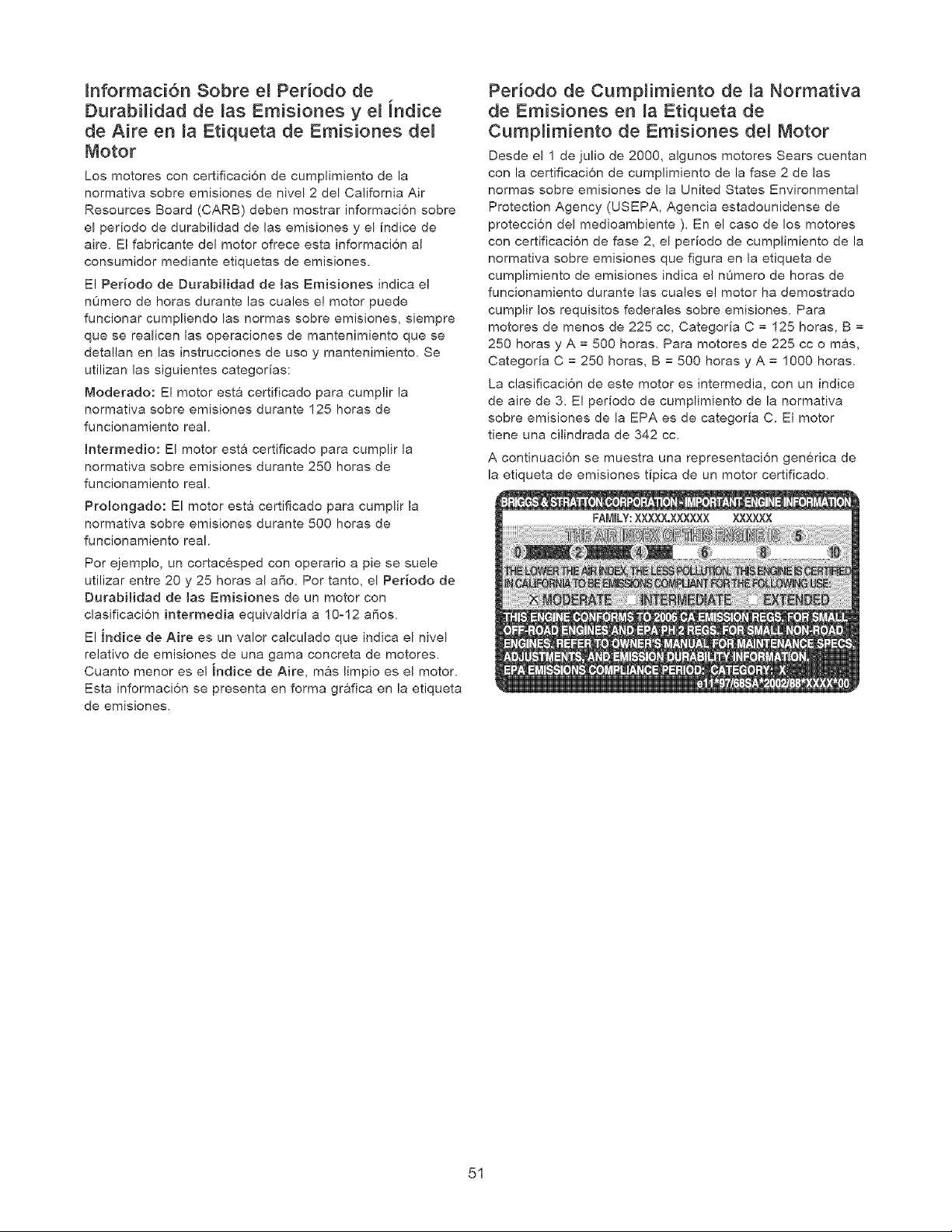
Jnformaci6n Sobre el Periodo de
Durabilidad de las Emisiones y e_ indice
de Aire en _a Etiqueta de Emisiones de_
Motor
Los motores con certificaci6n de cumplimiento de la
normativa sobre emisiones de nivel 2 del California Air
Resources Board (CARB) deben mostrar informaci6n sobre
el periodo de durabilidad de las emisiones y el indice de
aire. El fabricante de! motor ofrece esta informaci6n al
consumidor mediante etiquetas de emisiones.
El Per[odo de DurabHidad de [as Emisiones indica e!
n0mero de horas durante las cuales el motor puede
funcionar cumpliendo las normas sobre emisiones, siempre
que se realicen las operaciones de mantenimiento que se
detallan en las instrucciones de uso y mantenimiento, Se
utilizan las siguientes categorias:
Moderado: El motor esta certificado para cumplir la
normativa sobre emisiones durante 125 horas de
funcionamiento real.
Intermedio: El motor esta certificado para cumplir la
normativa sobre emisiones durante 250 horas de
funcionamiento real.
ProJongado: El motor esta certificado para cumplir la
normativa sobre emisiones durante 500 horas de
funcionamiento real.
Por ejemplo, un cortacesped con operario a pie se suele
utilizar entre 20 y 25 horas al aSo. Por tanto, el Periodo de
DurabiHdad de las Emisiones de un motor con
clasificaci6n intermedia equivaldria a 10-12 afios,
El indice de Aire es un valor calculado que indica el nivel
relativo de emisiones de una gama concreta de motores.
Cuanto menor es el indice de Aire, mas limpio es el motor.
Esta informacion se presenta en forma gr&fica en la etiqueta
de emisiones,
Periodo de Cump_imiento de _a Normativa
de Emisiones en ia Etiqueta de
CumpHmiento de Emisiones del Motor
Desde el 1 de julio de 2000, algunos motores Sears cuentan
con la certificacion de cumplimiento de la fase 2 de las
normas sobre emisiones de la United States Environmental
Protection Agency (USEPA, Agencia estadounidense de
protecci6n del medioambiente ). En e! caso de los motores
con certificaci6n de fase 2, el periodo de cumplimiento de la
normativa sobre emisiones que figura en la etiqueta de
cumplimiento de emisiones indica el nOmero de horas de
funcionamiento durante las cuales el motor ha demostrado
cumplir los requisitos federales sobre emisiones. Para
motores de menos de 225 cc, Categoria C = 125 horas, B =
250 horas y A = 500 horas, Para motores de 225 cc o mas,
Categoria C = 250 horas, B = 500 horas y A = 1000 horas,
La clasificacion de este motor es intermedia, con un indice
de aire de 3. El periodo de cumplimiento de la normativa
sobre emisiones de la EPA es de categoria C. El motor
tiene una cilindrada de 342 cc.
A continuaci6n se muestra una representaci6n generica de
la etiqueta de emisiones tipica de un motor certificado.
51

Your Home
For repair-in your home-of alJ major brand appliances,
lawn and garden equipment, or heating and cooling systems,
no matter who made it, no matter who sold it!
For,the replacement parts, accessories and
owner s manuals that you need to do-it-yourself.
For Sears professional installation of home appliances
and items like garage door openers and water heaters.
1-800-4-MY-HOME ® Anytime, day or night
(1o800-469-4663) (U.S.A. and Canada)
www.sears.corn www.sears.ca
our Home
For repair of carry-in items like vacuums, lawn equipment,
and electronics, call or go on-line for the nearest
Sears Parts & Repair Center.
1-800 -488 -1222 Anytime,dayor night(U.S.A.only)
www.sears.com
To purchase a protection agreement (U.S.A.)
or m?intenanc: agreement(Canada)on a pro:uct terviced by Sears:
1 800 827 6{}55 (U.S.A.) 1 800 361 6665 (Canada)
Parapedirservicioder paraci6n AuCanadapoo s rvice f an ais:
a domicilio, y para ordenar piezas: 1.800.LE.FOYERMC
1-888-S UoHOGAR sM (1o800o533-6937)
(1-888W84-6427) www.sears.ca
© Sears Brands, LLC
® Registered Trademark / TMTrademark / SMService Mark of Sears Brands, LLC
® Mama Registrada / TM Mama de Fabrica / SM Marca de Servicio de Sears Brands, LLC
MCMarque de commerce / MDMarque d6posCe de Sears Brands, LLC

