0099001821-00
PLEASE SAVE THIS OWNERS MANUAL AND READ BEFORE EACH USE.
This manual will explain how to use the battery charger safely and effectively.
Please read and follow these instructions and precautions carefully.
POR FAVOR CONSERVE ESTE MANUAL DEL USUARIO Y LEALO ANTES
DE CADA USO. En este manual le explica cómo utilizar el cargador de batería
de manera segura y conable. Por favor, lea y siga las siguientes instrucciones
y precauciones.
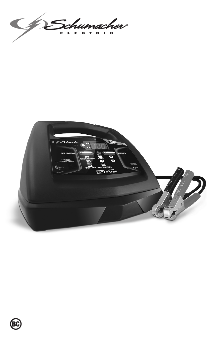
MODEL / MODELO:
SC1307
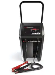
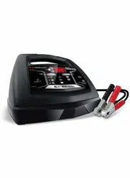
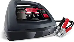
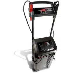
Automatic Battery Charger
Cargador de baterías automático
OWNERS MANUAL
MANUAL DEL USUARIO

CONTENTS
IMPORTANT SAFETY INSTRUCTIONS ....................................................................................3
PERSONAL SAFETY PRECAUTIONS ........................................................................................3
PREPARING TO CHARGE ..........................................................................................................4
CHARGER LOCATION .................................................................................................................4
DC CONNECTION PRECAUTIONS ............................................................................................4
FOLLOW THESE STEPS WHEN BATTERY IS INSTALLED IN VEHICLE ................................4
FOLLOW THESE STEPS WHEN BATTERY IS OUTSIDE VEHICLE ........................................5
GROUNDING AND AC POWER CORD CONNECTIONS .........................................................5
ASSEMBLY INSTRUCTIONS ......................................................................................................5
CONTROL PANEL ........................................................................................................................5
OPERATING INSTRUCTIONS .....................................................................................................6
MAINTENANCE AND CARE ........................................................................................................9
TROUBLESHOOTING AND ERROR CODES .............................................................................9
BEFORE RETURNING FOR REPAIRS ..................................................................................... 11
SPECIFICATIONS ......................................................................................................................11
LIMITED WARRANTY ................................................................................................................11
WARRANTY CARD ....................................................................................................................23
CONTENIDOS
INSTRUCCIONES IMPORTANTES DE SEGURIDAD ..............................................................12
PRECAUCIONES DE SEGURIDAD PERSONAL .....................................................................12
PREPARACIÓN PARA LA CARGA ...........................................................................................13
UBICACIÓN DEL CARGADOR ..................................................................................................13
PRECAUCIONES DE CONEXIÓN EN CC ................................................................................13
SIGA ESTOS PASOS CUANDO LA BATERÍA ESTÉ COLOCADA EN EL VEHÍCULO ...........14
SIGA ESTOS PASOS CUANDO LA BATERÍA SE ENCUENTRE FUERA DEL VEHÍCULO ....14
CONEXIONES A TIERRA Y ENERGÍA DE CA ..........................................................................14
INSTRUCCIONES DE MONTAJE .............................................................................................. 15
PANEL DE CONTROL ................................................................................................................15
INSTRUCCIONES DE OPERACIÓN .........................................................................................16
MANTENIMIENTO Y CUIDADO ................................................................................................19
LOCALIZACIÓN Y RESOLUCIÓN DE PROBLEMAS Y CODIGOS DE ERROR ..................... 19
ESPECIFICACIONES ................................................................................................................. 21
ANTES DE DEVOLVER A REPARACIONES ............................................................................21
GARANTÍA LIMITADA ................................................................................................................22
TARJETA DE GARANTÍA ...........................................................................................................23

• 3 •
1. IMPORTANT SAFETY INSTRUCTIONS
SAVE THESE INSTRUCTIONS.
1.1 SAVE THESE INSTRUCTIONS –
This manual contains important safety
and operating instructions.
1.2 Keep out of reach of children.
1.3 Do not expose the charger to rain or snow.
1.4 Use of an attachment not recommended
or sold by Schumacher
®
Electric
Corporation may result in a risk of re,
electric shock or injury to persons.
1.5 To reduce the risk of damage to electric
plug and cord, pull by the plug rather than
the cord when disconnecting charger.
1.6 An extension cord should not be used
unless absolutely necessary. Use of
improper extension cord could result
in a risk of re and electric shock. If an
extension cord must be used, make sure:
• The pins on plug of extension cord are
the same number, size and shape as
those of plug on charger.
• The extension cord is properly wired and
in good electrical condition
• The wire size is large enough for AC
ampere rating of charger as specied in
section 8.
1.7 Do not operate charger with damaged
cord or plug – replace the cord or plug
immediately.
1.8 Do not operate charger if it has received
a sharp blow, been dropped, or otherwise
damaged in any way; take it to a qualied
serviceman.
1.9 Do not disassemble charger; take it to
a qualied serviceman when service or
repair is required. Incorrect reassembly
may result in a risk of electric shock or re.
1.10 To reduce risk of electric shock, unplug
charger from outlet before attempting
any maintenance or cleaning. Turning off
controls will not reduce this risk.
1.11 WARNING:
RISK OF EXPLOSIVE GASES.
a. WORKING IN VICINITY OF A LEAD-
ACID BATTERY IS DANGEROUS.
BATTERIES GENERATE EXPLOSIVE
GASES DURING NORMAL BATTERY
OPERATION. FOR THIS REASON, IT IS
OF UTMOST IMPORTANCE THAT YOU
FOLLOW THE INSTRUCTIONS EACH
TIME YOU USE THE CHARGER.
b. To reduce risk of battery explosion,
follow these instructions and those
published by battery manufacturer
and manufacturer of any equipment
you intend to use in vicinity of battery.
Review cautionary markings on these
products and on engine.
2. PERSONAL SAFETY PRECAUTIONS
2.1 Consider having someone close enough
by to come to your aid when you work
near a lead-acid battery.
2.2 Have plenty of fresh water and soap
nearby in case battery acid contacts skin,
clothing, or eyes.
2.3 Wear complete eye protection and
clothing protection. Avoid touching eyes
while working near battery.
2.4 If battery acid contacts skin or clothing,
wash immediately with soap and water.
If acid enters eye, immediately ood
eye with running cold water for at least
10 minutes and get medical attention
immediately.
2.5 NEVER smoke or allow a spark or ame
in vicinity of battery or engine.
2.6 Be extra cautious, to reduce risk of
dropping a metal tool onto battery. It might
spark or short-circuit battery or other
electrical part that may cause explosion.
2.7 Remove personal metal items such as
rings, bracelets, necklaces, and watches
when working with a lead-acid battery. A
lead-acid battery can produce a short-
circuit current high enough to weld a ring
or the like to metal, causing a severe burn.
2.8 Use charger for charging only LEAD-ACID
(STD, AGM or deep-cycle) rechargeable
batteries with recommended rated
capacities of 12Ah (6V) and 22-59Ah (12V).
It is not intended to supply power to a low
voltage electrical system other than in a
starter-motor application. Do not use battery
charger for charging dry-cell batteries that
are commonly used with home appliances.
These batteries may burst and cause injury
to persons and damage to property.
2.9 NEVER charge a frozen battery.
2.10 WARNING: This product contains one
or more chemicals known to the State
of California to cause cancer and birth
defects or other reproductive harm.

• 4 •
3. PREPARING TO CHARGE
3.1 If necessary to remove battery from
vehicle to charge, always remove
grounded terminal from battery rst. Make
sure all accessories in the vehicle are off,
so as not to cause an arc.
3.2 Be sure area around battery is well
ventilated while battery is being charged.
3.3 Clean battery terminals. Be careful to
keep corrosion from coming in contact
with eyes.
3.4 Add distilled water in each cell until
battery acid reaches level specied by
battery manufacturer. Do not overll. For a
battery without removable cell caps, such
as valve regulated lead acid batteries,
carefully follow manufacturer’s recharging
instructions.
3.5 Study all battery manufacturer’s
specic precautions while charging and
recommended rates of charge.
3.6 Determine voltage of battery by referring
to car owner’s manual and make sure that
output voltage selector switch is set at
correct voltage. If charger has adjustable
charge rate, charge battery initially at
lowest rate.
4. CHARGER LOCATION
4.1 Locate charger as far away from battery
as DC cables permit.
4.2 Never place charger directly above
battery being charged; gases from battery
will corrode and damage charger.
4.3 Never allow battery acid to drip on
charger when reading electrolyte specic
gravity or lling battery.
4.4 Do not operate charger in a closed-in
area or restrict ventilation in any way.
4.5 Do not set a battery on top of charger.
5. DC CONNECTION PRECAUTIONS
5.1 Connect and disconnect DC output clips
only after setting any charger switches to
“off” position and removing AC cord from
electric outlet. Never allow clips to touch
each other.
5.2 Attach clips to battery and chassis, as
indicated in sections 6 and 7.
6. FOLLOW THESE STEPS WHEN BATTERY IS INSTALLED IN VEHICLE
WARNING: A SPARK NEAR THE
BATTERY MAY CAUSE A BATTERY
EXPLOSION. TO REDUCE THE RISK OF
A SPARK NEAR THE BATTERY:
6.1 Position AC and DC cords to reduce risk
of damage by hood, door, or moving
engine part.
6.2 Stay clear of fan blades, belts, pulleys, and
other parts that can cause injury to persons.
6.3 Check polarity of battery posts. POSITIVE
(POS, P, +) battery post usually has larger
diameter than NEGATIVE (NEG, N,–) post.
6.4 Determine which post of battery is
grounded (connected) to the chassis. If
negative post is grounded to chassis (as
in most vehicles), see (6.5). If positive
post is grounded to the chassis, see (6.6).
6.5 For negative-grounded vehicle, connect
POSITIVE (RED) clip from battery charger
to POSITIVE (POS, P, +) ungrounded post
of battery. Connect NEGATIVE (BLACK)
clip to vehicle chassis or engine block
away from battery. Do not connect clip to
carburetor, fuel lines, or sheet-metal body
parts. Connect to a heavy gauge metal
part of the frame or engine block.
6.6 For positive-grounded vehicle, connect
NEGATIVE (BLACK) clip from battery
charger to NEGATIVE (NEG, N, –)
ungrounded post of battery. Connect
POSITIVE (RED) clip to vehicle chassis
or engine block away from battery. Do
not connect clip to carburetor, fuel lines,
or sheet-metal body parts. Connect to a
heavy gauge metal part of the frame or
engine block.
6.7 When disconnecting charger, turn
switches to off, disconnect AC cord,
remove clip from vehicle chassis, and
then remove clip from battery terminal.
6.8 See Operating Instructions for length of
charge information.

• 5 •
7. FOLLOW THESE STEPS WHEN BATTERY IS OUTSIDE VEHICLE
WARNING: A SPARK NEAR THE
BATTERY MAY CAUSE A BATTERY
EXPLOSION. TO REDUCE THE RISK OF
A SPARK NEAR THE BATTERY:
7.1 Check polarity of battery posts. POSITIVE
(POS, P, +) battery post usually has a larger
diameter than NEGATIVE (NEG, N, –) post.
7.2 Attach at least a 24-inch long 6-gauge
(AWG) insulated battery cable to
NEGATIVE (NEG, N, –) battery post.
7.3 Connect POSITIVE (RED) charger clip to
POSITIVE (POS, P, +) post of battery.
7.4 Position yourself and free end of cable as
far away from battery as possible – then
connect NEGATIVE (BLACK) charger clip
to free end of cable.
7.5 Do not face battery when making nal
connection.
7.6 When disconnecting charger, always do
so in reverse sequence of connecting
procedure and break rst connection
while as far away from battery as
practical.
7.7 A marine (boat) battery must be removed
and charged on shore. To charge it on
board requires equipment specially
designed for marine use.
8. GROUNDING AND AC POWER CORD CONNECTIONS
8.1 This battery charger is for use on a
nominal 120 volt circuit. The charger
must be grounded, to reduce the risk of
electric shock. The plug must be plugged
into an outlet that is properly installed
and grounded in accordance with all local
codes and ordinances. The plug pins
must t the receptacle (outlet). Do not use
with an ungrounded system.
8.2 DANGER: Never alter the AC cord or
plug provided – if it does not t the outlet,
have a proper grounded outlet installed
by a qualied electrician. An improper
connection can result in a risk of an
electric shock or electrocution.
NOTE: Pursuant to Canadian
Regulations, use of an adapter plug
is not allowed in Canada. Use of an
adapter plug in the United States is not
recommended and should not be used.
8.3 USING AN EXTENSION CORD
The use of an extension cord is not
recommended. If you must use an
extension cord, follow these guidelines:
• Pins on plug of extension cord must be
the same number, size, and shape as
those of plug on charger.
• Ensure that the extension cord is
properly wired and in good electrical
condition.
• Wire size must be large enough for the
AC ampere rating of charger, as specied:
Length of cord (feet) 25 50 100 150
AWG* size of cord 16 14 14 12
*AWG-American Wire Gauge
9. ASSEMBLY INSTRUCTIONS
9.1 Remove all cord wraps and uncoil the
cables prior to using the battery charger.
9.2 Included with your charger are two cord
wrap cleats for storage of the clamp
cables. To install, align the two tabs with
the two receptacles on the back of the
charger and push until you hear a snap.
10. CONTROL PANEL
DIGITAL DISPLAY
The Digital Display gives a digital
indication of voltage or % of charge. The
display will show the battery VOLTAGE
when the charger is not charging a
battery. When it goes into charging mode,
the display will automatically change to
ON (to show charging has started) and
then show the percent-of-charge of the
battery being charged and either 6 or
12 (the battery voltage determined by
the charger). If you manually stop the
charging process (by pressing the Rate
Selection button) before the battery is fully
charged, the display will show OFF.
NOTE: During charging, the display will
go into sleep mode and will not show the
percentage of charge or voltage of the
battery. To turn the display back on, press
the Display button.
DISPLAY BUTTON
Use this button to set the function of the
digital display to one of the following:
• Battery % – The digital display shows
an estimated charge percentage of
the battery connected to the charger’s
battery clamps.
• Voltage – The Digital Display shows the
voltage at the charger battery clamps, in
DC volts.

• 6 •
RATE SELECTION BUTTON
Use this button to select one of the following:
• 6<>2A CHARGE/MAINTAIN – For
charging small and large batteries. Not
recommended for industrial applications.
• 30A BOOST – For quickly adding
energy to a severely discharged or large
capacity battery prior to Engine Start.
• 85A ENGINE START – Provides
additional amps for cranking an engine
with a weak or run-down battery. Always
use in combination with a battery.
NOTE: Once the charger has started
charging the battery; if you press the Rate
Selection button once, the output current is
shut off and the display will show OFF and
then the battery voltage. If you press the
Rate Selection button again, the current
will go back on at the same setting it was
when it was turned off.
LED INDICATORS
CLAMPS REVERSED (red) LED
ashing:The connections are
reversed.
ON(yellow/orange)LEDlit:
The charger is charging/boosting
the battery.
CHARGED/MAINTAINING(green)
LEDpulsing: The battery is fully
charged and the charger is in
maintain mode.
NOTE: See Operating Instructions for a
complete description of the charger modes.
BATTERY TYPE BUTTON
Use this button to select the battery type.
– Used in cars, trucks and
motorcycles, these batteries have vent caps
and are often marked “low maintenance” or
“maintenance-free”. This type of battery is
designed to deliver quick bursts of energy
(such as starting engines) and has a greater
plate count. The plates are thinner and have
somewhat different material composition.
Regular batteries should not be used for
deep-cycle applications.
– The Absorbed Glass Mat
construction allows the electrolyte to be
suspended in close proximity with the
plate’s active material. In theory, this
enhances both the discharge and recharge
efciency. The AGM batteries are a variant
of Sealed VRLA (valve regulated lead-acid)
batteries. Popular uses include high-
performance engine starting, power sports,
deep-cycle, solar and storage batteries.
11. OPERATING INSTRUCTIONS
WARNING: A spark near the battery may
cause an explosion.
NOTE: This charger is equipped with
an auto-start feature. Current will not be
supplied to the battery clamps until a
battery is properly connected. The clamps
will not spark if touched together (except
in Engine Start mode).
CHARGING A BATTERY
IN THE VEHICLE
1. Turn off all the vehicle’s accessories.
2. Keep the hood open.
3. Clean the battery terminals.
4. Place the charger on a dry, non-
ammable surface.
5. Lay the AC/DC cables away from any
fan blades, belts, pulleys and other
moving parts.
6. Connect the battery, following the
precautions listed in sections 6 and 7.
7. Connect the charger to an electrical
outlet.
8. Select the battery type and desired rate.
9. When charging is complete,
disconnect the charger from the AC
power, remove the clamps from the
vehicle’s chassis, and then remove
the clamp from the battery terminal.
CHARGING A BATTERY
OUTSIDE OF THE VEHICLE
1. Place battery in a well-ventilated area.
2. Clean the battery terminals.
3. Connect the battery, following the
precautions listed in sections 6 and 7.
4. Connect the charger to the electrical
outlet.
5. Select the battery type and desired rate.
6. When charging is complete,
disconnect the charger from the AC
power, disconnect the negative clamp,
and nally the positive clamp.
7. A marine (boat) battery must be
removed and charged on shore.
BOOST MODE
To select the Boost mode, press the Rate
Selection button until the yellow/orange
30A Boost LED lights solid. The ON
LED will light solid if battery is properly
connected and the boosting process will
start. While in Boost mode, the display
will show the voltage. If a bad battery is
detected, the display will show “bad / bat”
and an error code.
NOTE: Boost mode will remain energized
until the Rate Selection button is pressed.

• 7 •
CHARGE/MAINTAIN MODE
To select this mode, press the Rate
Selection button until the yellow/orange
6<>2A Charging/Maintaining LED lights.
The ON LED will light solid if battery is
properly connected and the charging
process will start. The display will show the
charger voltage. To change the mode on the
display, press the Display button. When the
battery is fully charged, the green Charged/
Maintaining LED will pulse. If charging
cannot be completed, the display will show
“bad / bat” and an error code. The battery
may be bad; have it checked.
NOTE: If the voltage of the battery is
under 12.7V, the charger will automatically
go into Boost mode, to quickly add
energy to the battery. To abort/skip the
temporary Boost and force the charger
into the Charge/Maintain mode, press the
Rate Selection button again (while still
boosting).
AUTOMATIC CHARGING MODE
When an Automatic Charge is performed,
the charger switches to the maintain mode
automatically after the battery is charged.
ABORTED CHARGE
If charging cannot be completed normally,
charging will abort. When charging aborts,
the charger’s output is shut off and the
display will show “bad / bat” and an error
code. Do not continue attempting to
charge this battery. Check the battery and
replace, if necessary.
DESULFATION MODE
The display will show “SUL” when a sulfated
battery is detected, and the charger will go
into desulfation mode. If the desulfation is
not successful after 10 hours, the charger
will go into abort mode. The display will
show “bAd / bAt / F02”.
COMPLETION OF CHARGE
Charge completion is indicated by
the green CHARGED/MAINTAINING
LED. When pulsing, the charger has
switched to the maintain mode of operation.
MAINTAIN MODE
(FLOAT MODE MONITORING)
When the green CHARGED/MAINTAINING
LED is lit, the charger has started
maintain mode. In this mode, the charger
keeps the battery fully charged by
delivering a small current when necessary.
If the charger has to provide its maximum
maintain current for a continuous 12 hour
period, it will go into abort mode (see
Aborted Charge section). This is usually
caused by a drain on the battery or the
battery could be bad.
MAINTAINING A BATTERY
The SC1307 charges and maintains both
6V and 12V batteries.
NOTE: The maintain mode technology
allows you to safely charge and maintain
a healthy battery for extended periods of
time. However, problems with the battery,
electrical problems in the vehicle, improper
connections or other unanticipated
conditions could cause excessive current
draws. As such, occasionally monitoring your
battery and the charging process is required.
BATTERY CHARGING TIMES
CCA = Cold Cranking Amps Ah = Amp Hour RC = Reserve Capacity
BATTERY SIZE/RATING
CHARGE RATE/TIME
6A<>2A
SMALL BATTERIES
Motorcycle, garden tractor, etc.
6-12 Ah 1½-2½ h
12-32 Ah 2½-7 h
CARS AND
TRUCKS
200-315 CCA 40-60 RC 7½-9½ h
315-550 CCA 60-85 RC 9½-12 h
550-1000 CCA 85-190 RC Maintain only
MARINE/DEEP-CYCLE
80 RC 12 h
140 RC Maintain only
160 RC Maintain only
180 RC Maintain only
Times are based on a 50% discharged battery and may change, depending on
age and condition of battery.

• 8 •
USING THE ENGINE START FEATURE
Your battery charger can be used to jump
start your car if the battery is low. Follow
all safety instructions and precautions for
charging your battery. Wear complete eye
protection and protective clothing.
WARNING: Using the ENGINE START
feature WITHOUT a battery installed in
the vehicle could cause damage to the
vehicle’s electrical system.
NOTE: During extremely cold weather, or
if the battery is under 2 volts, boost the
battery for 5 minutes before cranking the
engine.
NOTE: If you have charged the battery
and it still will not start your car, do not
use the Engine Start feature, or it could
damage the vehicle’s electrical system.
Have the battery checked.
1. With the charger unplugged from the
AC outlet, connect the charger to the
battery following the instructions given
in Charging a Battery in the Vehicle.
2. Plug the charger AC power cord into
the AC outlet.
3. With the charger plugged in and
connected to the battery and chassis,
select the ENGINE START rate. If
the battery is properly connected, the
yellow/orange 85A Engine Start LED
will light solid and the display will show
“ON”. If display shows “0.0”, check the
battery connections. If the display
does not show “On”, check the battery
connections. When the Engine Start
output is enabled the display will
show “rdy”.
4. Crank the engine until it starts or 5
seconds pass. If the engine does not
start, wait a few minutes before cranking
again. This allows the charger and
battery to cool down.
NOTE: After 3 minutes in Engine Start
mode, the charger will enter into a cool-
down period of 180 seconds, to allow the
charger and the battery to cool down.
The digital display indicates the remaining
cool down time in seconds. It starts at 180
and counts down to 0. After 3 minutes, the
digital display will change from displaying
the countdown to displaying “rdy”.
5. If the engine fails to start, use the 30A
Booster rate for 5 more minutes before
attempting to crank the engine again.
6. After the engine starts, unplug the AC
power cord before disconnecting the
battery clamps from the vehicle.
7. Clean and store the charger in a dry
location.
NOTE: If the engine does turn over but
never starts, there is not a problem with
the starting system; there is a problem
somewhere else with the vehicle. STOP
cranking the engine until the other problem
has been diagnosed and corrected.
USING THE BATTERY VOLTAGE TESTER
1. With the charger unplugged from the
AC outlet, connect the charger to the
battery, following the instructions given
in previous sections.
2. Plug the charger AC power cord into
the AC outlet.
3. Press the BATTERY TYPE button until
the correct type is indicated.
4. Read the voltage on the digital display.
Keep in mind that this reading is only a
battery voltage reading; a false surface
charge may mislead you. Compare the
reading to the following chart.
6V Battery
VoltageReading
12V Battery
VoltageReading
Battery
Condition
6.4 or more 12.8 or more Charged
6.1 to 6.3 12.2 to 12.7
Needs charging
Less than 6.1 Less than 12.2 Discharged
TESTER AND CHARGER
When rst turned on, the unit operates
only as a tester, not as a charger.
Selecting a charge rate activates the
battery charger and deactivates the
tester. Pressing the RATE SELECTION
button when the ENGINE START LED
is lit (except during the 180 second
cool down) will shut off the charger and
activate the tester.
POWER-UP IDLE TIME LIMIT
If no button is pressed within 10 minutes
after the battery charger is rst powered
up, the charger will automatically switch
from tester to charger if a battery is
connected. In that case, the charger will
be set to the Charging/Maintaining rate
and AGM battery type.
TESTING AFTER CHARGING
After the unit has been changed from
tester to charger (by selecting a desired
rate), it remains a charger. To change the
battery charger back to a tester, press the
RATE SELECTION button until all rate
LEDs are off.
NOTE: The battery tester is only designed
to test batteries. Testing a device with
a rapidly changing voltage could yield
unexpected or inaccurate results.

• 9 •
USING THE ALTERNATOR
PERFORMANCE TESTER
1. With the charger unplugged from the
AC outlet, connect the charger to the
battery, following the instructions given
in previous sections.
2. Plug the charger AC power cord into
the AC outlet.
3. Start the vehicle, rev the engine at
2000 rpm for 30 seconds and turn
on the vehicle’s headlights or other
accessories.
4. Read the voltage on the digital display.
If you get a reading between 13.4 volts
and 14.6 volts, the alternator is working
properly. If the reading is less than
13.4 volts or more than 14.6 volts, refer
to your vehicle’s manual or have the
charging system checked by a qualied
technician.
12. MAINTENANCE AND CARE
A minimal amount of care can keep your
battery charger working properly for years.
• Clean the clamps each time you are
nished charging. Wipe off any battery
uid that may have come in contact with
the clamps to prevent corrosion.
• Occasionally cleaning the case of the
charger with a soft cloth will keep the
nish shiny and help prevent corrosion.
• Coil the input and output cords neatly
when storing the charger. This will help
prevent accidental damage to the cords
and charger.
• Store the charger unplugged from the AC
power outlet in an upright position.
• Store inside, in a cool, dry place. Do not
store the clamps clipped together, on or
around metal, or clipped to the cables.
13. TROUBLESHOOTING AND ERROR CODES
Error Codes
CODE DESCRIPTION REASON/SOLUTION
bAd
bAT
F 01
The battery voltage is still under 10V
(for a 12V battery) or 5V (for a 6V
battery) after 2 hours of charging.
The battery could be bad. Have it checked or replaced.
SUL
The charger has detected a sulfated
battery.
The charger will go into desulfation mode. If the
desulfation is not successful after 10 hours, the charger
will go into abort mode.
bAd
bAT
F02
The charger cannot desulfate the
battery.
The battery could not be desulfated; have it checked or
replaced.
bAd
bAT
F03
The battery was unable to reach the
“full charge” voltage.
May be caused by trying to charge a large battery or
bank of batteries on too low of a current setting. Try
again with a higher current setting or have the battery
checked or replaced.
F04
The connections to the battery are
reversed.
The battery is connected backwards. Unplug the charger
and reverse the connections to the battery.
bAd
bAT
F05
The charger was unable to keep
the battery fully charged in maintain
mode.
The battery won’t hold a charge. May be caused by a drain
on the battery or the battery could be bad. Make sure there
are no loads on the battery. If there are remove them. If
there are none, have the battery checked or replaced.
bAd
bAT
F06
The charger detected that the battery
may be getting too hot (thermal
runaway).
The charger automatically shuts the current off if it
detects the battery may be getting too hot. Have the
battery checked or replaced.
If you get an error code, check the connections and settings and/or replace the battery.

• 10 •
Troubleshooting
PROBLEM POSSIBLE CAUSE REASON
Battery clamps do not
spark when touched
together.
The charger is equipped
with an auto-start feature.
It will not supply current to
the battery clamps until a
battery is properly connected.
The clamps will not spark if
touched together.
No problem; this is a normal
condition.
The charger will not
turn on when properly
connected.
AC outlet is dead.
Poor electrical connection.
Check for open fuse or circuit
breaker supplying AC outlet.
Check power cord and extension
cord for loose tting plug.
Engine start does
not work.
Drawing more than 85 amps.
Failure to wait 3 minutes (180
seconds) between cranks.
The charger may be
overheated.
Battery may be severely
discharged.
Crank time varies with the amount
of current drawn. If cranking draws
more than 85 amps, crank time
may be less than 5 seconds.
When the countdown from 180 to
0 is displayed, wait until the display
shows “rdy” for the next crank.
The thermal protector may have
tripped and needs a little longer
to reset. Make sure the charger
vents are not blocked. Wait and try
again.
On a severely discharged battery,
use the 30A Boost rate for 10 to 15
minutes, to help assist in cranking.
I cannot select a 6V or
12V setting.
The charger is equipped
with Auto Voltage Detection,
which automatically detects
the voltage and charges the
battery.
No problem; this is normal.
I press the display
button, but do not
see the percentage of
charge.
When rst connected to a
battery, the display shows
voltage only.
This is normal. The percentage
of charge is only displayed during
charging.
The display shows
“bAD / bAt / F 01 ”.
The battery voltage is still
below 10V (for a 12V battery)
or 5V (for a 6V battery) after 2
hours of charging.
The battery may be defective. Make
sure there are no loads on the
battery. If there are, remove them.
If there are none, have the battery
checked or replaced.
The display shows
“bAD / bAt / F02”.
Desulfation was unsuccessful,
after 10 hours.
The battery may be defective. Have
battery checked or replaced.
The display shows
“bAD / bAt / F05”.
Lack of progress is detected
after 12 hours in Maintain mode.
The battery won’t hold a charge.
May be caused by a drain on the
battery or the battery could be bad.
Make sure there are no loads on the
battery. If there are remove them.
If there are none, have the battery
checked or replaced.

• 11 •
14. BEFORE RETURNING FOR REPAIRS
Ifthesesolutionsdonoteliminatetheproblem,orformoreinformation
abouttroubleshooting,contactcustomerserviceforassistance:
www.batterychargers.com
orcall1-800-621-5485,Monday-Friday7:00am to 5:00pm CST
For REPAIR OR RETURN, contact Customer Service at 1-800-621-5485. DO NOT SHIP
UNIT until you receive a RETURN MERCHANDISE AUTHORIZATION (RMA) number from
Customer Service at Schumacher Electric Corporation.
15. SPECIFICATIONS
Input ..................................................... 120V AC
@
60Hz, 4A continuous/19A intermittent
Output ..............................................................................................6V DC, 2A continuous
12V DC, 2A/6A intermittent (120 sec. @ 2A, 60 sec. @ 6A)
6V/12V DC, 12A/30A intermittent (120 sec. @ 12A, 60 sec. @ 30A)
6V/12V DC, 85A intermittent (5 sec. on, 180 sec. off)
16. LIMITED WARRANTY
WARRANTY NOT VALID IN MEXICO.
SCHUMACHERELECTRICCORPORATION,801BUSINESSCENTERDRIVE,
MOUNTPROSPECT,IL60056-2179,MAKESTHISLIMITEDWARRANTYTOTHE
ORIGINAL RETAIL PURCHASER OF THIS PRODUCT. THIS LIMITED WARRANTY
IS NOT TRANSFERABLE OR ASSIGNABLE.
Schumacher Electric Corporation (the “Manufacturer”) warrants this battery charger
for two (2) years from the date of purchase at retail against defective material or
workmanship that may occur under normal use and care. If your unit is not free from
defective material or workmanship, Manufacturer’s obligation under this warranty is
solely to repair or replace your product with a new or reconditioned unit at the option
of the Manufacturer. It is the obligation of the purchaser to forward the unit, along with
proof of purchase and mailing charges prepaid to the Manufacturer or its authorized
representatives in order for repair or replacement to occur.
Manufacturer does not provide any warranty for any accessories used with this product
that are not manufactured by Schumacher Electric Corporation and approved for use
with this product. This Limited Warranty is void if the product is misused, subjected
to careless handling, repaired, or modied by anyone other than Manufacturer or if
this unit is resold through an unauthorized retailer. Manufacturer may void this Limited
Warranty if a “warranty void if removed” label is removed from the product.
Manufacturer makes no other warranties, including, but not limited to, express, implied or
statutory warranties, including without limitation, any implied warranty of merchantability
or implied warranty of tness for a particular purpose. Further, Manufacturer shall
not be liable for any incidental, special or consequential damage claims incurred by
purchasers, users or others associated with this product, including, but not limited to,
lost prots, revenues, anticipated sales, business opportunities, goodwill, business
interruption and any other injury or damage. Any and all such warranties, other than the
limited warranty included herein, are hereby expressly disclaimed and excluded. Some
states do not allow the exclusion or limitation of incidental or consequential damages or
length of implied warranty, so the above limitations or exclusions may not apply to you.
This warranty gives you specic legal rights and it is possible you may have other rights
which vary from this warranty.
THIS LIMITED WARRANTY IS THE ONLY EXPRESS LIMITED WARRANTY AND THE
MANUFACTURER NEITHER ASSUMES OR AUTHORIZES ANYONE TO ASSUME
OR MAKE ANY OTHER OBLIGATION TOWARDS THE PRODUCT OTHER THAN
THIS WARRANTY.
Schumacher
®
and the Schumacher logo are registered trademarks
of Schumacher Electric Corporation.

• 12 •
1. INSTRUCCIONES IMPORTANTES DE SEGURIDAD
GUARDE ESTAS INSTRUCCIONES.
1.1 GUARDE ESTAS INSTRUCCIONES –
Este manual contiene instrucciones
operativas y de seguridad de importancia.
1.2 Mantener fuera del alcance de los niños.
1.3 No exponga el cargador a la lluvia
o a la nieve.
1.4 El uso de un accesorio no recomendado
o suministrado por Schumacher
®
Electric
Corporation puede provocar riesgo de
incendio, descarga eléctrica o lesiones a
personas.
1.5 Para reducir el riesgo de daños al
enchufe o cable eléctrico, jale del enchufe
en lugar de jalar del cable al desconectar
el cargador.
1.6 No se debe utilizar un alargador a menos
que resulte absolutamente necesario. El
uso de un alargador inadecuado puede
provocar riesgo de incendio o descarga
eléctrica. En caso de que deba utilizarse
un alargador, asegúrese de que:
• Los pasadores en el enchufe del
alargador posean el mismo número,
tamaño y forma que aquellos presentes
en el enchufe del cargador.
• El alargador se encuentre correctamente
conectado y en buenas condiciones
eléctricas; y
• El tamaño del cable sea lo
sucientemente extenso para el
amperaje en CA del cargador como se
especica en la sección 8.
1.7 No utilice el cargador si el mismo posee
un enchufe o cable dañado; substituya el
cable o el enchufe inmediatamente por
una persona calicada en el ramo.
1.8 No utilice el cargador si el mismo recibió
un golpe fuerte, si se cayó o si sufrió
daños de cualquier otra forma; hágalo
revisar por una persona capacitada que
efectúe reparaciones.
1.9 No desarme el cargador; hágalo revisar
por una persona capacitada que efectúe
reparaciones cuando necesite servicio
de mantenimiento o una reparación.
Volver a ensamblar el cargador en forma
incorrecta puede provocar riesgo de
incendio o descarga eléctrica.
1.10 Para reducir el riesgo de descarga
eléctrica, desenchufe el cargador del
tomacorriente antes de intentar llevar a
cabo cualquier actividad de mantenimiento
o limpieza. El simple apagado de los
controles no reducirá este riesgo.
1.11 ADVERTENCIA:
RIESGO DE GASES EXPLOSIVOS.
a. RESULTA PELIGROSO TRABAJAR EN
FORMA CERCANA A UNA BATERÍA DE
PLOMO. LAS BATERÍAS GENERAN
GASES EXPLOSIVOS DURANTE
SU NORMAL FUNCIONAMIENTO.
POR ESTE MOTIVO, RESULTA DE
SUMA IMPORTANCIA QUE SIGA LAS
INSTRUCCIONES CADA VEZ QUE
UTILIZA EL CARGADOR.
b. Para reducir el riesgo de explosión de
una batería, siga estas instrucciones y
aquellas publicadas por el fabricante
de la batería y por el fabricante de
cualquier equipo que intente utilizar
en la proximidad de la batería. Revise
las pautas de precaución en estos
productos y en el motor.
2. PRECAUCIONES DE SEGURIDAD PERSONAL
2.1 Considere la idea de que alguna persona
se encuentre cerca suyo para poder
ayudarlo cuando trabaje en forma
cercana a una batería de plomo-ácido.
2.2 Cuente con una gran cantidad de agua
potable y jabón a mano en caso de que el
ácido de la batería tenga contacto con su
piel, ropa u ojos.
2.3 Utilice protección visual y corporal
completa, incluyendo gafas de seguridad
y prendas de protección. Evite tocar sus
ojos mientras trabaje en forma cercana a
la batería.
2.4 Si el ácido de la batería tiene contacto
con su piel o su ropa, lave de inmediato
el área afectada con agua y jabón. En
caso de que ingrese ácido en un ojo,
sumerja el mismo de inmediato bajo agua
potable corriente por al menos 10 minutos
y obtenga atención médica en forma
inmediata.
2.5 NUNCA fume o permita la presencia de
chispas o llamas en la proximidad de una
batería o motor.
2.6 Tenga especial cuidado para reducir el
riesgo de dejar caer una herramienta
de metal sobre la batería. Esto podría
provocar chispas o un cortocircuito en la
batería o en cualquier otra pieza eléctrica
que podría provocar una explosión.
2.7 No utilice elementos personales de metal
tales como anillos, pulseras, collares y
relojes al trabajar con una batería de
plomo-ácido. Una batería de plomo-

• 13 •
ácido puede producir una corriente de
cortocircuito lo sucientemente elevada
como para soldar un anillo o provocar
efectos similares sobre el metal,
causando una quemadura de gravedad.
2.8 Utilice este cargador solamente para cargar
baterías recargables de tipo PLOMO-
ÁCIDO (estándar, AGM o ciclo-profundo)
con recomienda usar capacidad de la
batería de 12Ah (6V) y 22-59Ah (12V).
Este cargador no está destinado a
suministrar energía a sistemas eléctricos
de baja tensión más que en una aplicación
de un motor de arranque. No utilice este
cargador de batería para cargar baterías
de pila seca que por lo general se utilizan
con artefactos domésticos. Estas baterías
podrían explotar y provocar lesiones a
personas o daño a la propiedad.
2.9 NUNCA cargue una batería congelada.
2.10 ADVERTENCIA: Este producto
contiene una o más sustancias químicas
conocidas en el Estado de California
como causantes de cáncer y defectos de
nacimiento u otros daños reproductivos.
3. PREPARACIÓN PARA LA CARGA
3.1 Si resulta necesario extraer la batería
del vehículo para cargarla, siempre retire
el terminal con descarga a tierra en
primer lugar. Asegúrese de que todos los
accesorios en el vehículo se encuentren
apagados para evitar la formación de
arcos eléctricos.
3.2 Asegúrese de que el área que rodea a
la batería se encuentre bien ventilada
mientras se carga la batería.
3.3 Limpie los terminales de la batería antes
de cargar la batería. Durante la limpieza,
evite que la corrosión producida por aire
tenga contacto con sus ojos.
3.4 Agregue agua destilada a cada pila hasta
que el ácido de la batería alcance el
nivel especicado por el fabricante de la
batería. No provoque derrames. En lo que
concierne a baterías que no cuentan con
tapas extraíbles para pilas, tales como
baterías de plomo-ácido reguladas por
válvulas (VRLA, por sus siglas en inglés),
siga cuidadosamente las instrucciones de
recarga del fabricante.
3.5 Controle todas las precauciones
especícas establecidas por el fabricante
de la batería al realizar la carga, así
también como los índices de carga
recomendados.
3.6 Determine la tensión de la batería al
consultar el manual del usuario del
vehículo y asegúrese de que el interruptor
de selección de la tensión de salida
se encuentre establecido en la tensión
correcta (en su caso). Si el cargador
posee un índice de carga ajustable,
cargue la batería en el menor índice en
primer lugar.
4. UBICACIÓN DEL CARGADOR
4.1 Ubique el cargador a la mayor distancia
posible de la batería como lo permitan los
cables de CC.
4.2 Nunca ubique el cargador directamente
por encima de la batería que se carga; los
gases de la batería corroerán y dañarán
el cargador.
4.3 Nunca permita que el ácido de la batería
gotee sobre el cargador al leer el peso
especíco del electrolito o al cargar la
batería.
4.4 No utilice el cargador en un área cerrada o
restrinja la ventilación en cualquier forma.
4.5 No ubique la batería encima del cargador.
5. PRECAUCIONES DE CONEXIÓN EN CC
5.1 Conecte y desconecte las pinzas de
salida CC. sólo después de haber
establecido todos los interruptores del
cargador a la posición de “apagado” (si
es aplicable) y de haber desconectado
el enchufe de C.A. del tomacorriente
eléctrico. Nunca permita que las pinzas
tengan contacto entre sí.
5.2 Sujete las pinzas a la batería y al chasis,
como se indica en en las secciones 6 y 7.

• 14 •
6. SIGA ESTOS PASOS CUANDO LA BATERÍA ESTÉ COLOCADA EN EL VEHÍCULO
ADVERTENCIA:
UNA CHISPA PROVOCADA CERCA
DE LA BATERÍA PUEDE CAUSAR LA
EXPLOSIÓN DE LA BATERÍA. PARA
REDUCIR EL RIESGO DE PROVOCAR
CHISPAS CERCA DE LA BATERÍA:
6.1 Ubique los cables de CA y CC
adecuadamente para reducir el riesgo
de daños por la cubierta, la puerta y las
piezas móviles o calientes del motor.
6.2 Manténgase alejado de las paletas del
ventilador, correas, poleas y otras piezas
que podrían provocar lesiones.
6.3 Verique la polaridad de los bornes de
la batería. El borne POSITIVO (POS,
P, +) de la batería generalmente posee
un diámetro mayor al borne NEGATIVO
(NEG, N, -).
6.4 Determine qué borne de la batería
hace descarga a tierra (se encuentra
conectado) con el chasis. Si el borne
negativo hace descarga a tierra con el
chasis (como en la mayor parte de los
vehículos), ver el paso (6.5). Si el borne
positivo hace descarga a tierra con el
chasis, ver el paso (6.6).
6.5 En un vehículo con descarga a tierra
por borne negativo, conecte el gancho
POSITIVO (ROJO) del cargador de
batería al borne POSITIVO (POS, P, +) sin
descarga a tierra de la batería. Conecte
el gancho NEGATIVO (NEGRO) al chasis
del vehículo o al bloque motor alejado
de la batería. No conecte el gancho al
carburador, líneas de combustible o
cuerpos metálicos. Conecte a una pieza
metálica de calibre grueso del marco o
del bloque motor.
6.6 En un vehículo con descarga a tierra
por borne positivo, conecte el gancho
NEGATIVO (NEGRO) del cargador de
batería al borne NEGATIVO (NEG, N, -)
sin descarga a tierra de la batería.
Conecte el gancho POSITIVO (ROJO)
al chasis del vehículo o al bloque motor
alejado de la batería. No conecte al
carburador, líneas de combustible o
cuerpos metálicos. Conecte a una pieza
metálica de calibre grueso del marco o
del bloque motor.
6.7 Al desconectar el cargador, apague todos
los interruptores (en su caso), desconecte
el cable de C.A., retire el gancho del
chasis del vehículo y luego retire el gancho
del terminal perteneciente a la batería.
6.8 Vea Instrucciones de Operación para
duración de la carga.
7. SIGA ESTOS PASOS CUANDO LA BATERÍA SE ENCUENTRE FUERA DEL VEHÍCULO
ADVERTENCIA:
UNA CHISPA PROVOCADA CERCA
DE LA BATERÍA PUEDE CAUSAR LA
EXPLOSIÓN DE LA BATERÍA. PARA
REDUCIR EL RIESGO DE PROVOCAR
CHISPAS CERCA DE LA BATERÍA:
7.1 Verique la polaridad de los bornes de
la batería. El borne POSITIVO (POS,
P, +) de la batería generalmente posee
un diámetro mayor al borne NEGATIVO
(NEG, N, -).
7.2 Sujete al menos un cable aislado de
batería de 24 pulgadas (61 cm) de largo
con calibre 6 según el Calibre americano
de cables (AWG, por sus siglas en inglés)
al borne NEGATIVO (NEG, N, -) de la
batería.
7.3 Conecte el gancho POSITIVO (ROJO) del
cargador al borne POSITIVO (POS, P, +)
de la batería.
7.4 Ubíquese junto con el extremo libre del
cable que previamente sujetó al borne
NEGATIVO (NEG, N, -) de la batería a
la mayor distancia posible de la batería.
Luego conecte el gancho NEGATIVO
(NEGRO) del cargador al extremo libre
del cable.
7.5 No se ubique en posición frontal a la
batería al realizar la conexión nal.
7.6 Al desconectar el cargador, siempre
hágalo en forma inversa al procedimiento
de conexión y realice la primera conexión
tan lejos de la batería como sea posible.
7.7 Una batería marina (para barcos) se
debe retirar y cargar en tierra. Para
realizar una carga a bordo se necesitan
equipamientos especialmente diseñados
para uso marino.
8. CONEXIONES A TIERRA Y ENERGÍA DE CA
8.1 Este cargador de batería está destinado a
un uso en un circuito con tensión nominal
de 120 V. El cargador debe poseer una
descarga a tierra para reducir el riesgo
de descargas eléctricas. El enchufe
se debe conectar a un tomacorriente
adecuadamente instalado y que cuente con
descarga a tierra de acuerdo con todas las

• 15 •
ordenanzas y códigos. Los pasadores del
enchufe deben adaptarse al receptáculo
(tomacorriente). No utilizar con un sistema
que no posea descarga a tierra.
8.2 PELIGRO: Nunca altere el cable o
enchufe de C.A. suministrado, si no se
ajusta al tomacorriente, haga instalar un
tomacorriente adecuado con descarga
a tierra por medio de un electricista
capacitado. Una conexión inadecuada
puede provocar un riesgo de descarga
eléctrica o electrocución.
NOTA: De acuerdo a las Leyes
Canadienses, el uso de un enchufe
adaptador no es permitido en el Canada.
El uso de un enchufe como adaptador
no se recomienda y no debe ser utilizado
Estados Unidos.
8.3 USO DE UN CABLE DE EXTENSIÓN
El uso de una extensión no se
recomienda. Si debe usar una extensión,
siga estas pautas:
• Las clavijas del enchufe del cable de
extensión debe ser el mismo número,
tamaño y forma que las del enchufe del
cargador.
• Asegúrese de que el cable de extensión
esté conectado correctamente y en
buenas condiciones eléctricas.
• El tamaño del cable debe ser lo
sucientemente extenso para el calibre
de amperios del cargador de CA, como
se especica a continuación:
Longitud del cable (pies)
25 50 100 150
Calibre del cable AWG*
16 14 14 12
*AWG-American Wire Gauge
9. INSTRUCCIONES DE MONTAJE
9.1 Desenrede todos los cordones y extienda
los cables antes de usar el cargador de
baterías.
9.2 Junto con el cargador de batería,
encontrará dos abrazaderas cubiertas
para almacenar los prensacables. Para la
instalación, alinee las dos presillas para
que coincidan con los dos receptáculos
en la parte trasera del cargador, y empuje
hasta que escuche un ruido seco.
10. PANEL DE CONTROL
PANTALLA DIGITAL
La pantalla digital proporciona una
indicación digital de la tensión o % de
carga. La pantalla mostrará el VOLTAJE
de la batería cuando el cargador no
se encuentre cargandola. Cuando
se programe en el modo de carga, la
carátula cambiará automáticamente a On
(encendido–para mostrar que la carga
ha comenzado) y después mostrará
el porcentaje-de-carga obtenido por la
batería. y asi indicado 6 o 12 (el voltaje de
de carga que el cargador haya detectado
en la batería. Si usted, manualmente
detiene el proceso de carga (una vez
que presiona el botón de Rate Selection
(selección de la velocidad) antes que la
batería esté completamente cargada, la
carátula se Off (apagara).
NOTA: Durante la carga, la pantalla
entra en el modo de suspensión y no
se mostrará el porcentaje de carga o
la tensión de la batería. Para activar la
pantalla, pulse el botón de pantalla.
BOTÓN DE PANTALLA
Utilice este botón para ajustar la función
de la pantalla digital a uno de los
siguientes:
• % de batería – La pantalla digital muestra
un porcentaje de carga estimado de la
batería conectada a las pinzas de batería
pertenecientes al cargador.
• Tensión– La pantalla digital muestra
la tensión en las pinzas de batería
pertenecientes al cargador en volts de C.C
BOTÓN DE SELECCIÓN DE VELOCIDAD
Utilice este botón para establecer una de
las siguientes selecciones:
• 6<>2A CHARGE/MAINTAIN (cargar/
mantener) – Para la carga de baterías
pequeñas y grandes. No se recomienda
para aplicaciones industriales.
• 30A BOOST (impulso rápido) – Para
la incorporación rápida de la energía a
una batería muy descargada o de gran
capacidad antes de arrancar el motor.
• 85AENGINESTART(arranquede
motor) – Proporcionar amplicadores
adicionales para el arranque de un motor
con una débil o agotado la batería.
Siempre utilice en combinación con una
batería.
NOTA: Un vez que el cargador ha
comenzado a cargar la batería, si
presiona el botón de Selección de
Velocidad una vez, la corriente de salida
se apaga y la pantalla mostrará OFF
(Apagado) y después el voltaje de la
batería. Si vuelve a presionar el mismo
botón otra vez, la corriente regresará al
mismo punto en donde estuvo apagada.

• 16 •
INDICADORES LED
LED CLAMPS REVERSED
(pinzasinvertidas)[rojo]parpadea:
Las conexiones están inversas.
LEDON[amarillo/naranja]
encendido:El cargador está
cargando/impulsando la batería.
LED CHARGED/MAINTAINING
(cargado/mantenimiento)[verde]
pulsante: La carga de la bateria está
completa y que el cargador cambió a
modo mantener.
NOTA: Consulte la sección Instrucciones
de Operación para obtener una descripción
completa de los modos del cargador.
BOTÓN DE TIPO DE BATERÍA
Utilice este botón para establecer el tipo
de batería a cargar.
– Este tipo de batería generalmente
se utiliza en automóviles, camiones y
motocicletas. Este tipo de baterías cuentan
con tapas de ventilación y a menudo se
las clasica como de “bajo mantenimiento”
o “libre de mantenimiento”. Este tipo de
baterías está diseñado para suministrar
rápidas ráfagas de energía (tales como los
arranques de motores) y poseen un mayor
recuento en placa. Las placas asimismo
serán más delgadas y poseerán una
composición de materiales algo diferente.
Las baterías regulares no se deben utilizar
en aplicaciones de ciclo profundo.
– La construcción de la malla de
bra de vidrio absorbente permite la
suspensión del electrolito en extrema
proximidad con el material activo de la
placa. En teoría, esto aumenta tanto la
eciencia de la descarga como de la
recarga. Las baterías AGM constituyen
una variedad de las baterías Selladas
VRLA (de plomo-ácido reguladas por
válvula). Entre sus usos más comunes
se encuentran baterías con arranque de
motor de alto rendimiento, para deportes
intensos, de ciclo profundo, solares y de
acumuladores.
11. INSTRUCCIONES DE OPERACIÓN
ADVERTENCIA: Una chispa provocada
cerca de la batería puede causar una
explosión.
NOTA: Este cargador está equipado con
un auto-recticador. La corriente no llegará
a las pinzas de la batería hasta que la
batería esté apropiadamente conectada.
Signicado, las pinzas no harán corto si se
juntan una con otra (excepto en el modo
de arranque de motor).
CARGA DE LA BATERÍA
EN EL VEHÍCULO
1. Apague todos los accesorios del
vehículo.
2. Mantenga el cofre abierto.
3. Limpie las terminales de la batería.
4. Coloque el cargador sobre una
supercie seca y no inamable.
5. Coloque los cables de CA / CC lejos
de las aspas del ventilador, bandas,
poleas y otras partes móviles.
6. Conectar la batería según las
instrucciones que indicadas en las
secciones 6 y 7.
7. Conecte el cargador a la toma de
corriente.
8. Seleccione el tipo de batería y la
velocidad deseada.
9. Cuando la carga está completa,
desconecte el cargador de la
alimentación de CA, retire la pinza del
chasis del vehículo y quite la pinza de
la terminal de la batería.
CARGA DE LA BATERÍA
FUERA DEL VEHÍCULO
1. Coloque la batería un área bien
ventilada.
2. Limpie las terminales de la batería.
3. Conectar la batería según las
instrucciones que indicadas en las
secciones 6 y 7.
4. Conecte el cargador a la toma de
corriente.
5. Seleccione el tipo de batería y la
velocidad deseada.
6. Cuando la carga está completa,
desconecte el cargador de la corriente
AC, desconecte la pinza negativa, y
por último la pinza positiva.
7. Una batería marina (de barco) se
debe retirar y cargar en tierra.
MODO DE BOOST
Para seleccionar el modo Boost (impulso
rápido), pulse el botón de selección de
velocidad hasta que se ilumine de manera
constante la luz LED (amarillo/naranja)
de Boost de 30 A. La luz LED ON se
mantendrá constante si la batería está
conectada correctamente, y el proceso de
Boost se iniciará. En el modo de Boost, la
pantalla mostrará el voltaje. Si se detecta
una batería defectuosa, la pantalla mostrará
“bAd / bAt” y un código de error.
NOTA: El modo de Boost permanecerá
energizado hasta que se pulse el botón de
selección de velocidad.

• 17 •
MODO DE CARGA/MANTENIMIENTO
Para seleccionar este modo, presione el
botón de selección de velocidad hasta que
la luz LED amarilla/anaranjada de 6<>2 A
de Charging/Maintaining se enciende. La
luz LED ON se mantendrá constante si
la batería está correctamente conectada;
entonces, el proceso de carga se iniciará.
La pantalla mostrará el voltaje del cargador.
Para cambiar el modo en la pantalla,
presione el botón de la pantalla. Cuando
la batería esté completamente cargada, la
luz LED verde de Charged/Maintaining
se iluminará de manera intermitente. Si no
se puede completar la carga, la pantalla
mostrará “bAd / bAt” y un código de error.
La batería puede encontrarse en mal
estado; revísela.
NOTA: Si el voltaje de la batería es
inferior a 12,7, el cargador entrará
automaticamente en modo BOOST para
agregar energía de manera rápida a la
batería. Para abortar/evitar el incremento
temporal y forzar al cargador en el modo
de mantenimiento/carga, pulse el botón
de Selección de Velocidad nuevamente
(mientras continua impulsar).
MODO DE CARGA AUTOMÁTICA
Cuando se realiza una carga automática,
el cargador cambia del maintain mode
[modo de mantenimiento] automáticamente
después que la batería se cargue.
CARGA ANULADA
Si no se puede completar la carga
normalmente, la carga se anulará. Cuando
la carga se interrumpe y la salida del
cargador se apaga y la pantalla mostrará
“bAd / bAt” y un código de error. No continúe
tratando de cargar esta batería. Compruebe
la batería y reemplazar si es necesario.
MODO DE DESULFATACIÓN
La pantalla mostrará “SUL” cuando
se detecte una batería sulfatada,
y el cargador entrará en modo de
desulfatación. Si la desulfatación no tiene
éxito después de 10 horas, el cargador
pasará al modo de anulada. La pantalla
mostrará “bAd / bAt / F02”.
FINALIZACIÓN DE LA CARGA
La nalización de la carga se indica con el
LED CARGADO/MANTENIMIENTO
(verde). Al pulsar, el cargador ha pasado
de modo de función a mantenimiento.
MODO DE MANTENIMIENTO
(MONITOREO A MODO DE FLOTE)
Cuando la luz LED CARGADO/
MANTENIMIENTO
(verde) esté
pulsando, quiere decir que pasó al modo de
mantenimiento. En este modo el cargador
mantiene la batería totalmente cargada
mediante una pequeña corriente cuando
corresponda. Si el cargador tiene que
funcionar al máximo en corriente continua
de mantenimiento a un periodo de 12 horas,
se transladará al Modo de Interrumpir
(véase la sección Carga Anulada). Esto es
ocacionalmente causado por una pérdida
de energía en la batería o la batería está
dañada. Asegúrese que no escape de carga
en la batería y si la hay evítela, en caso
contrario, verique o reémplace la batería.
MANTENIENDO UNA BATERÍA
El SC1307 carga y mantiene las baterías
de 6 y 12 voltios, manteniéndolas a carga
completa.
NOTA: La tecnología de modo de
mantenimiento le permite cargar de
forma segura y mantener una batería
en buen estado durante largos períodos
de tiempo. Ahora, los problemas con
la batería, problemas eléctricos del
vehículo, conexiones equivocadas u otras
condiciones que surgan, podrías causar
absorsión de corriente excesiva. De modo
que, ocasionalmente seguimiento de su
batería y el proceso de carga se requiere.
TIEMPOS DE CARGA
CCA = Amperaje de arranque en frío Ah = Amp/hora RC = Capacidad de reserva
TAMAÑO / ÍNDICE DE LA BATERÍA
ÍNDICE /
TIEMPO DE CARGA
6A<>2A
BATTERÍAS PEQUEÑAS
Motocicleta, tractor de jardín, etc.
6-12 Ah 1½-2½ h
12-32 Ah 2½-7 h
CARS AND
TRUCKS
200-315 CCA 40-60 RC 7½-9½ h
315-550 CCA 60-85 RC 9½-12 h
550-1000 CCA 85-190 RC Mantenimiento sólo
MARINA / CICLO PROFUNDO
80 RC 12 h
140 RC Mantenimiento sólo
160 RC Mantenimiento sólo
180 RC Mantenimiento sólo
Los tiempos que se informan son para baterías con un 50% de carga antes de volver
a cargar.

• 18 •
UTILIZAR LA FUNCIÓN DE
ENCENDIDO DE MOTOR
El cargador de batería se puede utilizar
para arrancar el auto si la batería está
baja. Siga todas las instrucciones y
precauciones de seguridad en la carga de
la batería. Use protección completo de los
ojos y la ropa de protección.
ADVERTENCIA: Utilizando la función
de arranque del motor SIN la batería
instalada en el vehículo, dañará el
sistema eléctrico.
NOTA: Bajo clima frío extremo o si la
batería es inferior a 2 volts, impulsar la
batería por 5 minutos antes de poner en
marcha el motor.
NOTA: Si usted ya ha cargado la batería
y aún no arranca el auto, no utilice la
opción de arranque, porque esto podría
dañar el sistema eléctrico del vehículo.
Haga revisar la batería.
1. Con el cargador desenchufado del
tomacorriente de CA, conecte el
cargador a la batería siguiendo las
instrucciones que guran en la sección
Carga de la Batería en el Vehículo.
2. Enchufe el cable de alimentación de CA
del cargador al tomacorriente de CA.
3. Con el cargador enchufado y
conectado a la batería del ENGINE
START. Si la batería está conectada
correctamente, la luz LED amarilla/
anaranjada de 85A Engine Start se
iluminará de manera constante, y la
pantalla mostrará “On”. Si la pantalla
muestra “0.0”, revise las conexiones
de la batería. Si la pantalla no muestra
“On”, compruebe las conexiones de la
batería. Cuando la salida de arranque
del motor esté activada, la pantalla
mostrará “rdy”.
4. Déle arranque al motor hasta que
se ponga en marcha o que pasen
5 segundos. Si el motor no arranca
espera unos minutos antes de
intentarlo de nuevo. Esto permite al
cargador y la batería que se enfríen.
NOTA: Después de 3 minutos en el
modo de arranque del motor, el cargador
entrará en un período de enfriamiento
de 180 segundos para permitir que el
cargador y la batería se enfríen. La
pantalla digital indica el tiempo restante
de enfriamiento en segundos. La cuenta
regresiva comienza en 180 y llega hasta
0. Después de 3 minutos, la pantalla
digital cambiará de mostrar la cuenta a
mostrar “rdy”.
5. Si el motor no arranca, cutilice el
ajuste Booster 30A por 5 minutos más
antes de darle arranque nuevamente.
6. Después de que el motor se puso
en marcha desenchufe el cable
de alimentación de CA antes de
desconectar las pinzas de la batería
del vehículo.
7. Limpie y guarde el cargador en un
lugar seco.
NOTA: Si el motor gira, pero no enciende,
no existe un problema con el sistema de
arranque, sino en cualquier otra parte
del vehículo. DEJE de darle arranque
al motor hasta que el otro problema se
diagnostique y se corrija.
UTILIZAR EL PROBADOR DE TENSIÓN
DE BATERÍA
1. Con el cargador desenchufado del
tomacorriente de CA, conecte el
cargador a la batería siguiendo las
instrucciones que guran en las
secciones anteriores.
2. Enchufe el cable de alimentación de CA
del cargador en el tomacorriente de CA.
3. Presione el botón TIPO DE BATERÍA
hasta que el tipo correcto se indique.
4. Lea la tensión de la pantalla digital.
Tenga en cuenta que esta lectura es
solamente una lectura de la tensión
de la batería, una falsa carga de
supercie podría engañarlo. Compare
la lo mostrado con la siguiente gráca.
Indicación
deVoltaje
a 6 Voltios
Indicación
deVoltaje
a 12 Voltios
Condición
de la Batería
6,4 o más 12,8 o más Cargada
6,1 a 6,3 12,2 a 12,7
Necesita ser
cargada
Menos de
6,1
Menos de
12,2
Descargada
PROBADOR Y CARGADOR
Cuando se enciende por primera vez, la
unidad funciona sólo como probador, no
como cargador. Al seleccionar el índice
de carga active el cargador de la batería
y desactive el probador. Si presiona el
botón SELECCIÓN DE VELOCIDAD
cuando el LED ARRANQUE DEL MOTOR
está encendido (excepto durante los 180
segundos de enfriamiento) cerrará el
cargador y activará el probador.

• 19 •
ENCENDER EL LÍMITE DE TIEMPO
DE INACTIVIDAD
Si el botón TIPO DE BATERÍA se presiona
dentro de los 10 minutos después de que
el cargador de batería se encendió por
primera vez, el cargador automáticamente
cambiará de probador a cargador si la
batería está conectada. En ese caso, el
cargador se ajustará a la seleccióne de
velocidad de cargado/mantenimiento y el
tipo de batería AGM.
PROBAR DESPUÉS DE CARGAR
Después de que la unidad ha sido
cambiada de probador a cargador
(mediante la selección de una velocidad)
permanece como cargador. Para cambiar
el cargador de la batería de nuevo a
probador presione el botón SELECCIÓN
DE VELOCIDAD hasta que todos los LED
están apagados.
NOTA: El probador de batería solo
está diseñado para probar baterías. La
prueba de un dispositivo con un voltaje
que cambie rápidamente podría arrojar
resultados inesperados o imprecisos.
UTILIZACIÓN DE UN PROBADOR
DERENDIMIENTO DEL ALTERNADOR
1. Con el cargador desenchufado del
tomacorriente de CA, conecte el
cargador a la batería siguiendo las
instrucciones que guran en las
secciones anteriores.
2. Enchufe el cable de alimentación de CA
del cargador al tomacorriente de CA.
3. Arranque el vehículo, accelere el motor
a 2000 rpm durante 30 segundos y
encienda las luces delanteras u otros
accesorios.
4. Lea la tensión de la pantalla digital.
Si usted obtiene una lectura de
entre 13,4 voltios y 14,6 voltios,
el alternador está trabajando
propiamente. Si la lectura es menor a
los 13.4 voltios o más de 14,6 voltios,
consulte el manual de su vehículo
o pida que el sistema de carga sea
supervisado por un técnico calicado.
12. MANTENIMIENTO Y CUIDADO
Con cuidados mínimos puede mantener
el cargador de baterías funcionando
correctamente durante años.
• Limpie las pinzas cada vez que termine
de usar el cargador. Limpie el uido de
la batería que podría haber estado en
contacto con las pinzas para evitar la
corrosión.
• De vez en cuando, limpie la carcasa
del cargador con un paño suave para
conservar el acabado brillante y evitar
la corrosión.
• Enrolle los cables de entrada y salida
cuidadosamente cuando almacene el
cargador. Esto ayudará a evitar daños
accidentales a los cables y el cargador.
• Guarde el cargador desenchufado de la
toma de alimentación de CA en posición
vertical.
• Debe conservarse en un lugar fresco y
seco. No guarde las pinzas unidas entre sí,
alrededor del metal, o unidos a los cables.
13. LOCALIZACIÓN Y RESOLUCIÓN DE PROBLEMAS Y CODIGOS DE ERROR
Codigos de Error
CÓDIGO DESCRIPCIÓN RAZÓN/SOLUCIÓN
bAd
bAT
F 01
El voltaje de la batería todavía está
debajo de 10V (para una batería
12V) o de 5V (para una batería 6V)
después de 2 horas de carga.
La batería podría estar en malas condiciones.
Verifíquela o reemplácela.
SUL
El cargador ha detectado una
batería sulfatada.
El cargador pasará al modo de desulfatación. Si la
desulfatación no tiene éxito después de 10 horas,
el cargador pasará al modo de anulada.
bAd
bAT
F02
El cargador no puede desulfatar
la batería.
La batería no puede desulfatada.Verifíquela o
reemplácela.
bAd
bAT
F03
La batería no alcanzó “su carga
completa”, voltaje.
Podría ser causado al intentar cargar una batería
grande o baterías en serie en un ajuste bajo de
energía. Intente otra vez con un ajuste más alto de
corriente o verifíque o reempláce la batería.

• 20 •
CÓDIGO DESCRIPCIÓN RAZÓN/SOLUCIÓN
F04
Las conexiones a la batería están
invertidas.
La batería está conectada en forma inversa. Desconecte
el cargador y haga la conexión en forma correcta.
bAd
bAT
F05
El cargador no puede alimentar
la batería cargada el el modo de
mantenimiento.
La batería no mantiene la carga. Podría ser
causado por un escape en la batería o la batería
podría estar en malas condiciones. Cerciórese de
que no haya fugas en la batería. Si no hay ninguno,
verifíque o reempláce la batería.
bAd
bAT
F06
El cargador ha detectado que la
batería se está sobrecalentando
(fuga térmica).
El cargador detiene la corriente, automáticamente,
si detecta que la batería se está sobrecalentando.
Revise la batería o reemplácela.
Si usted obtiene un código de la error, usted tiene que comprobar las conexiones, los niveles
de carga y/o substituir la batería.
LocalizaciónySolucióndeProblemas
PROBLEMA CAUSA POSIBLE SOLUCIÓN
Las pinzas de la
batería no hacen corto
al juntarse una con
otra.
Este cargador está equipado
con un auto-recticador. Este
no permitirá paso de corriente si
las pinzas de la batería no están
conectadas en forma correcta.
Signicado, las pinzas no harán
corto si se juntan una con otra.
No hay problema; es una condición
normal.
El cargador no se
enciende incluso al
estar bien conectado.
Tomacorriente de CA fuera de
funcionamiento.
Conexión eléctrica deciente.
Controle la posible presencia de
fusibles abiertos o disyuntores que
suministren energía al tomacorriente
de CA.
Revise el cable de extensión para
cable y enchufe suelta.
Sin inicio al arrancar
el motor.
Consumo mayor a 85
amperios.
No espera 3 minutos (180
segundos) entre los arranques.
El cargador podría encontrarse
en estado de recalentamiento.
La batería podría encontrarse
severamente descargada.
El tiempo de arranque varía según
la cantidad de corriente consumida.
Si el arranque consume más de 200
amperios, el tiempo de arranque
podría ser menor a 5 segundos.
Cuando la pantalla muestra la
cuenta regresiva de 180 a 0
segundos, esperar hasta que
muestre “rdy” antes del proximo
arranque.
El protector térmico podría
encontrarse desconectado y
necesitar un mayor tiempo de
descanso. Asegúrese de que los
ventiladores del cargador no se
encuentren bloqueados. Aguarde un
momento y pruebe nuevamente.
Con batería muy descargada, utilizar
el ajuste de 30A Boost durante 10 a
15 minutos, para ayudar a ayudar en
el arranque.

• 21 •
PROBLEMA CAUSA POSIBLE SOLUCIÓN
No puedo seleccionar
los 6 o 12 Voltios.
El Cargador está equipado con
Detección de Auto Voltaje, que
automáticamente detecta el
voltaje y carga la batería.
No hay problema; es una condición
normal.
Presiono el botón de
visualización, pero no
veo el porcentaje de
carga.
Cuando se conecta por primera
vez a una batería, la pantalla
sólo muestra voltaje.
Esto es normal. El porcentaje de
carga sólo se muestra durante la
carga.
La pantalla muestra
“bAD / bAt / F 01 ”.
El voltaje de la batería todavía
está debajo de 10V (para una
batería 12V) o de 5V (para una
batería 6V) después de 2 horas
de carga.
La batería puede estar defectuosa.
Asegúrese de que no hay cargas en
la batería. Si hay eliminarlos. Si no
hay ninguno, verifíque o reempláce
la batería.
La pantalla muestra
“bAD / bAt / F02”.
La desulfatación falló después
de 10 horas.
La batería podría estar en
malas condiciones. Verifíquela o
reemplácela.
La pantalla muestra
“bAD / bAt / F05”.
La falta de progreso se detecta
después de 12 horas en el
modo de mantenimiento.
La batería no mantiene la carga.
Puede ser causada por una batería
descargada o la batería podría
ser malo. La batería puede estar
defectuosa. Asegúrese de que no
hay cargas en la batería. Si hay
eliminarlos. Si no hay ninguno,
verifíque o reempláce la batería.
14. ESPECIFICACIONES
Entrada ................................................. 120V CA @ 60Hz, 4A continua / 19A intermitente
Salida ....................6V CC, 2A continua; 12V CC, 2A / 6A (120 seg. @ 2A, 60 seg. @ 6A)
6V / 12V CC, 12A / 30A (120 seg. @ 12A, 60 seg. @ 30A)
85A intermitente (5 seg. en, 180 seg. off)
15. ANTES DE DEVOLVER A REPARACIONES
Siestassolucionesnoeliminanelproblemao
sideseaobtenermásinformación
sobrelasolucióndeproblemas,póngaseencontacto
coneldepartamentodeservicioalclientepararecibirasistencia:
www.batterychargers.com
o llame 1-800-621-5485
Lunes-viernes7:00am to 5:00pm CST
Para REPARACIÓN O DEVOLUCIÓN, comuníquese con Servicios al Cliente al
1-800-621-5485. NO ENVÍE LA UNIDAD hasta que usted reciba AUTORIZACIÓN
DE DEVOLUCIÓN DE MERCANCÍA (RMA) de Servicios al Cliente de Schumacher
Electric Corporation.

• 22 •
16. GARANTÍA LIMITADA
GARANTIA LIMITADA NO VALIDA EN MEXICO.
SCHUMACHERELECTRICCORPORATION,801BUSINESSCENTERDRIVE,
MOUNT PROSPECT, IL 60056-2179, REALIZA LA PRESENTE GARANTÍA
LIMITADA AL COMPRADOR MINORISTA ORIGINAL DE ESTE PRODUCTO. LA
PRESENTE GARANTÍA LIMITADA NO PUEDE TRANSFERIRSE NI CEDERSE.
Schumacher Electric Corporation (el “Fabricante”) otorga garantía por este cargador
de batería por un plazo de dos (2) años contados a partir de la fecha de compra
por menor por la existencia de cualquier material o de mano de obra defectuosos
que pudieran surgir por su uso y cuidado normal. Si su unidad cuenta con material
defectuoso o defectos de mano de obra, la obligación de los Fabricantes, conforme a la
presente garantía, será simplemente reparar o sustituir el producto por uno nuevo o por
una unidad reparada, a elección del fabricante. Es obligación del comprador enviar la
unidad con comprobante de compra y los gastos de envío prepagos al fabricante o a sus
representantes autorizados para que ésta se pueda reparar o reemplazar.
El Fabricante no presta garantía por lo accesorios utilizados con este producto que no
sean los fabricados por Schumacher Electric Corporation y que no estén aprobados
para su uso con este producto. La presente Garantía Limitada será nula si el producto
se utiliza en forma errónea, se trata de manera inadecuada, es reparado o modicado
por personas que nos sean el Fabricante o si esta unidad es revendida a través de un
vendedor minorista no autorizado. El fabricante pudiera anular esta Garantía Limitada
si la etiqueta “warranty void if removed” es removida del producto.
El Fabricante no realiza ninguna otra garantía, incluidas, a título enunciativo, las
garantías expresas, implícitas o legales, incluidas, a modo de ejemplo, las garantías
implícitas de comerciabilidad o adecuación a un n especíco. Asimismo, el Fabricante
no será responsable ante reclamos por daños accidentales, especiales ni directos en
los que incurran los compradores, usuarios u otras personas asociadas al producto,
incluidas, a título enunciativo, los ingresos y ganancias no percibidos, ventas anticipadas,
oportunidades comerciales, el buen nombre, la interrupción de la actividad comercial
o cualquier otro daño que haya provocado. Todas las garantías, excepto la garantía
limitada incluida en el presente, por medio de la presente, quedan expresamente
anuladas y excluidas. Algunos estados no permiten la exclusión ni la limitación de los
daños accidentales ni directos o el plazo de garantía implícita, por lo que las limitaciones
o exclusiones mencionadas anteriormente podrían no corresponder con su caso. La
presente garantía le otorga derechos legales especícos y es probable que usted cuente
con otros derechos que podrían diferir de los incluidos en la presente garantía.
LA PRESENTE GARANTÍA LIMITADA ES LA ÚNICA GARANTÍA LIMITADA
EXPRESA Y EL FABRICANTE NO ASUME NI AUTORIZA A NADIE A ASUMIR O
A ADQUIRIR NINGUNA OTRA OBLIGACIÓN RESPECTO DEL PRODUCTO QUE NO
SEA LA PRESENTE GARANTÍA.
Schumacher
®
y el logo Schumacher son marcas registradas
de Schumacher Electric Corporation.

• 23 •
¡AHORRE EN EL ENVÍO! ¡ACTIVE SU GARANTÍA EN LÍNEA-LA FORMA MAS RÁPIDA Y FÁCIL!
Visitenuestrapáginaenwww.batterychargers.compararegistrarsuproductoenlínea.
(¿No tiene acceso al internet? Llene la tarjeta de garantía y envíela.)
WARRANTY CARD / TARJETA DE GARANTÍA
SAVE ON POSTAGE! ACTIVATE YOUR WARRANTY ONLINE – THE QUICK AND EASY WAY!
Gotowww.batterychargers.comtoregisteryourproductonline.
(No internet access? Send in the completed warranty card.)
2 YEAR LIMITED
WARRANTY PROGRAM
REGISTRATION
MODEL: _____________________DESCRIPTION: ________________________
This is the only express limited warranty, and the manufacturer neither assumes
nor authorizes anyone to assume or make any other obligation. There is no other
warranty, other than what is described in the product owner’s manual.
The warranty card should be submitted within 30 days of purchase. The customer
must keep the ORIGINAL receipt because it will be required for any warranty claims.
This warranty is not transferable. Send warranty card only.
DO NOT SEND UNIT TO THIS ADDRESS FOR REPAIR.
Mailthiscardto: SchumacherElectricCorporation
801BusinessCenterDrive
MountProspect,IL60056-2179
Name ______________________________________________________________
Street Address _______________________________________________________
City ________________________________State _________ Zip Code _________
Phone _____________________Email ___________________________________
Store Name Where Purchased ___________________ Date of Purchase _________
Store Location ____________________ UPC Number ________________________
Serial Number ______________________________________ (SEE PRODUCT)
For faster warranty activation, go to www.batterychargers.com to register your product online.
PROGRAMA DE REGISTRO
DE 2-AÑOS DE GARANTÍA
LIMITADA
MODELO: ____________________DESCRIPCIÓN: ________________________
Esta es la única garantía limitada expresa, y el productor no autoriza ni otorga
a alguien a realizar alguna otra obligación. No existe ninguna otra garantía
más que la descrita en el manual del dueño.
La tarjeta de garantía debe enviarse durante los primeros 30 días después de la
compra. El cliente debe mantener el recibo de compra ORIGINAL como
comprobante, el cual le otorga todo derecho a cualquier reclamo de garantía.
Esta garantía no es transferible. Envie tarjeta de garantía solamente.
NO ENVÍE LA UNIDAD A ESTA DIRECCIÓN PARA SU REPARACIÓN.
Enviarestatarjetaa: SchumacherElectricCorporation
801BusinessCenterDrive
MountProspect,IL60056-2179
Nombre ____________________________________________________________
Dirección ___________________________________________________________
Ciudad __________________________Estado ____________ C.P. _____________
Tel: ________________________ Correo electrónico _________________________
Nombre de la Tienda donde se Compró ____________ Fecha de compra _________
Localización de la Tienda ____________ Numero de Serie ____________________
Código de barras ___________________________ (CONSULTE EL PRODUCTO)
Para una activación más rápida, visite nuestra página de internet en www.batterychargers.com
1. WARRANTY CARD
2. TARJETA DE GARANTÍA