OPERATING INSTRUCTIONS AND OWNER’S MANUAL
READ INSTRUCTIONS CAREFULLY: Read and follow all
instructions. Place instructions in a safe place for future
reference. Do not allow anyone who has not read these
instructions to assemble, light, adjust or operate the heater.
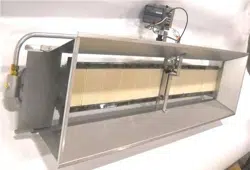
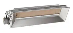
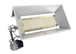
HEATSTAR High-Intensity Infrared Heaters
HS4040 HS9100S
HS8060 HS9120
MODELS
Installer: Leave this manual with the appliance. Consumer: Retain this manual for future reference.
If the information in this manual is not followed exactly, a fire or explosion
may result causing property damage, personal injury or loss of life.
WARNING:
— Do not store or use gasoline or other flammable vapors and liquids in the vicinity of this or any
other appliance.
— WHAT TO DO IF YOU SMELL GAS
• Shutoffgassupply
• Donottrytolightappliance
• Donottouchanelectricalswitch;donotuseanyphoneinyourbuilding
• Immediatelycallyourgassupplierfromaneighbor’sphone.
Followthegassupplier’sinstructions
• Ifyoucannotreachyourgassupplier,calltheredepartment
—Installationandservicemustbeperformedbyaqualiedinstaller,serviceagencyorthegas
supplier.
Thisisanunventedgas-redheater.Itusesair(oxygen)fromtheareainwhichitisused.Adequate
combustion and ventilation air must be provided. Refer to page 4.
ENERCOGROUPINC.,4560W.160THST.,CLEVELAND,OHIO44135•216-916-3000
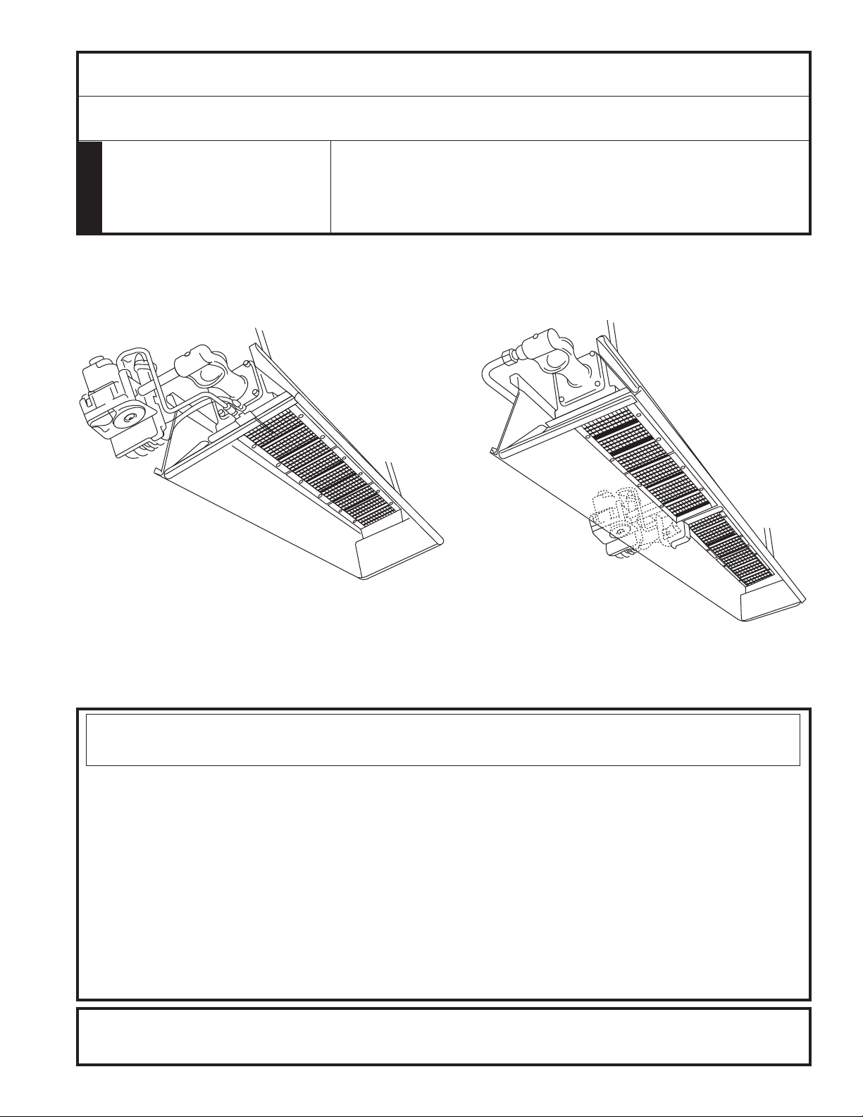
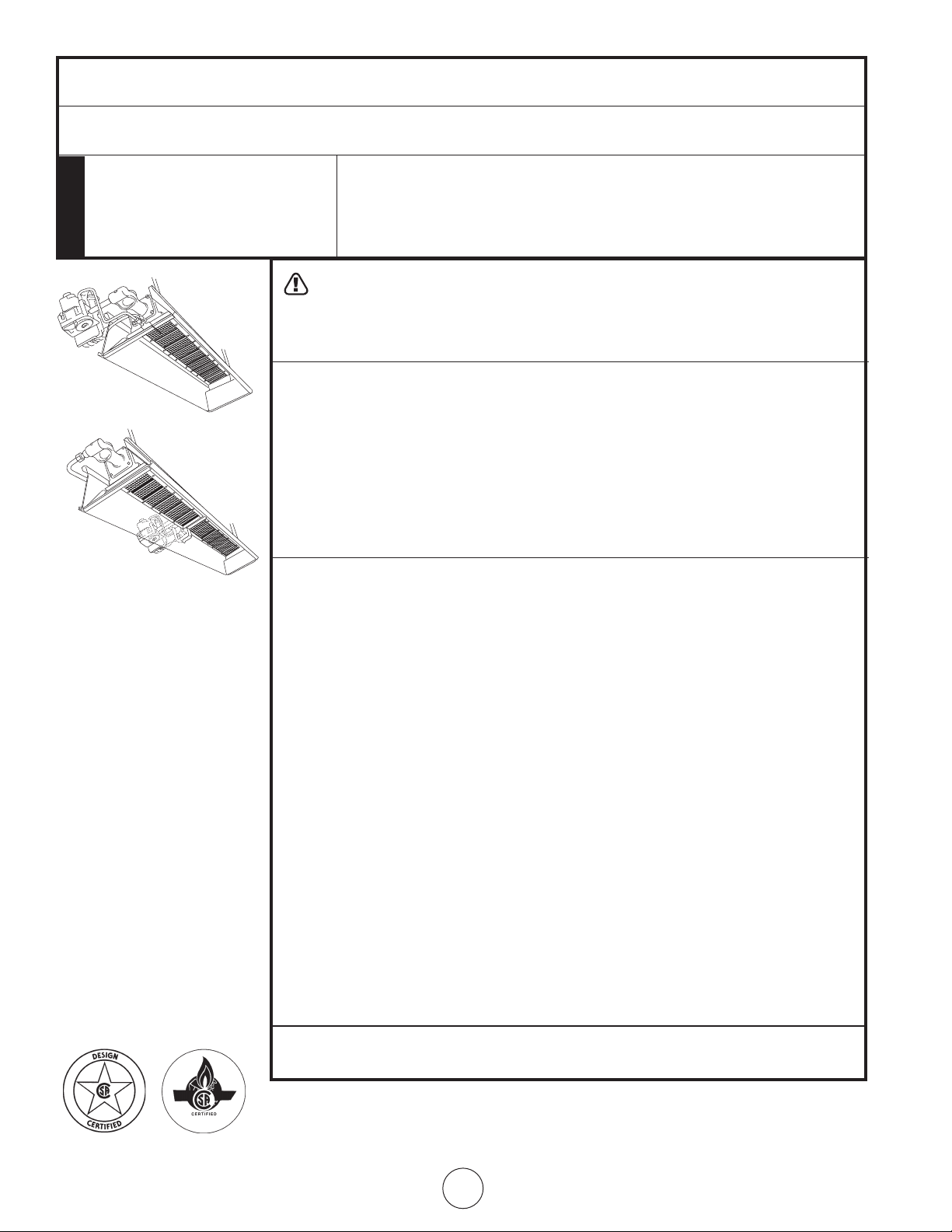
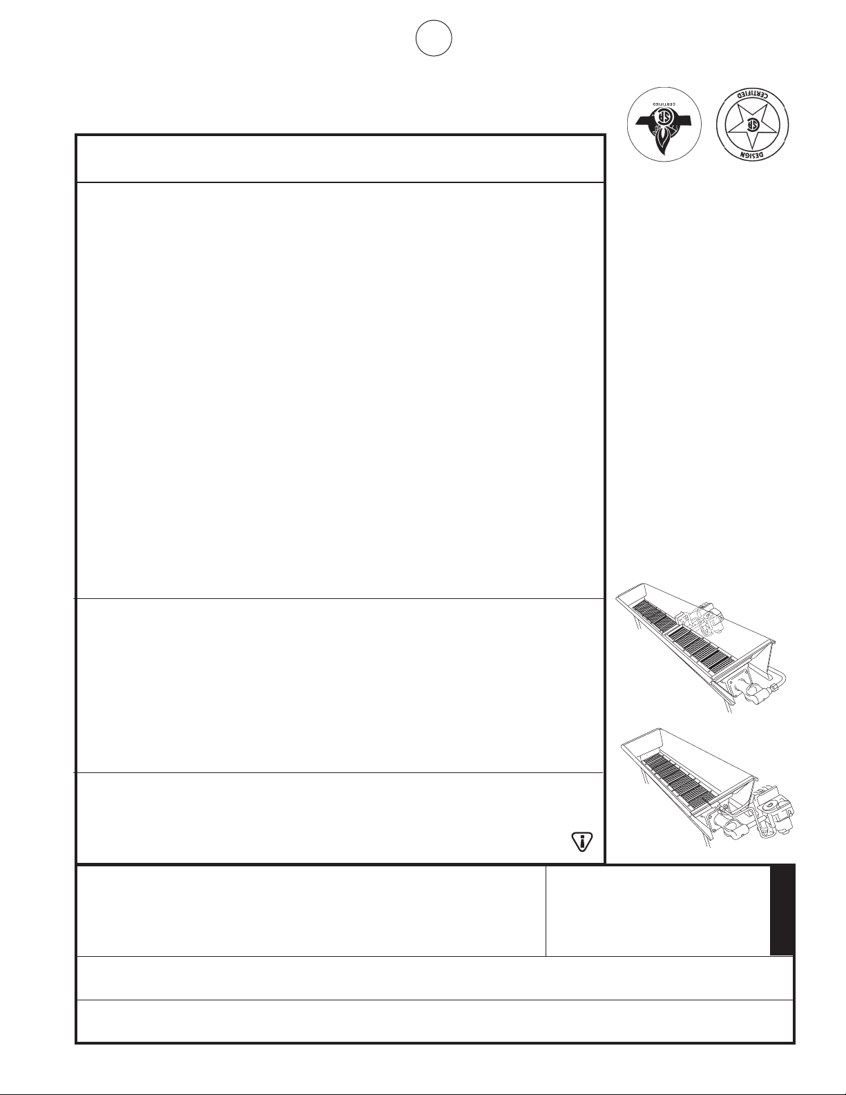
4000 & 8000 Models 9000 Models
18650 Rev. A 06/08
2
Enerco Group, Inc. |Gas-Fired Infra-Red Space Heaters OperatingInstructionsandOwner’sManual
CONTENTS
General Information .......................................................... 3
Clearances ........................................................................ 3
Gas Supply ........................................................................ 3
Gas Pressure ..................................................................... 3
Electrical ........................................................................... 4
Thermostat & Location ...................................................... 4
Ventilation ........................................................................ 4
Operations ........................................................................4
Cleaning Information ........................................................ 4
Connection diagram for flame rod current
foramerecticationsystems ......................................5
Thermostat ....................................................................... 5
Replacement parts ............................................................7
Control system replacement parts ................................... 10
WARNING: Improper installation, adjustment,
alteration, service or maintenance can cause property
damage, injury or death. Read the installation, opera-
tion, and maintenance instructions thoroughly before
installing or servicing this equipment. For assistance
oradditionalinformationconsultaqualiedinstaller,
service agency, or gas supplier.
WARNING: When used without fresh air, heater
may give off CARBON MONOXIDE, an odorless poi-
sonous gas. OPEN WINDOW AN INCH OR TWO FOR
FRESH AIR WHEN USING HEATER.
WARNING: This heater is equipped with a PILOT
LIGHT SAFETY SYSTEM. DO NOT TAMPER WITH PILOT
LIGHT SAFETY SYSTEM.
WARNING: If heater shuts off, do not relight
until you provide fresh air. If heater keeps shutting off,
have it serviced. Keep burner and control clean. Open
door for 5 minutes.
Maintain clearances as shown in Figure 1 or on heater nameplate.
•DONOTUSEMATCHOROTHERFLAME
FOR LEAK TESTING.
•DONOTEXCEED1/2PSIINLETPRESSURETOHEATER.
DANGER:
Carbonmonoxidepoisoningmayleadtodeath.
Carbon Monoxide Poisoning:
Earlysignsofcarbonmonoxidepoisoningresemble
the flu, with headaches, dizziness, or nausea. If you
have these signs, the heater may not be working
properly. Get fresh air at once! Have heater serviced.
Somepeoplearemoreaffectedbycarbonmonoxide
than others. These include pregnant women, persons
with heart or lung disease or anemia, those under the
influence of alcohol, and those at high altitudes.
CAUTION:
•Neverconnectgasvalveorthermostattolinevoltage
or a transformer.
•Iftheinfra-redcolorofthegridbecomesdullwhen
the building furnace is operating, consult gas supplier
on correct gas supply piping sizes.
•Thisheaterisforindoorinstallationonly!
NOTE Gasket binder material used in this heater assem-
bly will temporarily emit an odor and/or vapor. This
conditionwillclearupinapproximately20minutes
and thereafter will not reoccur. Refer to page 4 for
ventilation.
THE STATE OF CALIFORNIA REQUIRES THE
FOLLOWING WARNING:
WARNING: Combustion by-products produced
whenusingthisproductcontaincarbonmonoxide,
a chemical known to the State of California to cause
cancerandbirthdefects(orotherreproductiveharm).
3
OperatingInstructionsandOwner’sManualEnerco Group, Inc. | Gas-Fired Infra-Red Space Heaters
1. GENERAL INFORMATION
Your heater comes fully assembled and is tested at a.
the factory for proper gas and input as stated on
the name plate.
Before proceeding with the installation, be sure to b.
inspect for damages. Freight company must be noti-
edofanydamagesandrequestthataninspection
be made by the freight company. HEAT STAR will send
replacement parts for damaged parts only after receiv-
ing a signed inspection report to prove the liability of
the freight company.
Do not attempt to operate heater with any other gas c.
than that indicated on the heater name plate.
The installation of heater must conform with local d.
building codes or, in absence of local codes, with the
National Fuel Gas Code, ANSI Z223.1a/NFPA54. In
Canada, refer to Can 1-B146.1 and B149.2.
Plugged 1/8” N.P.T. Test Gage Connection is located e.
on the Heater Gas Control or a ¼” N.P.T. Connection is
located on the outside of the Cast Venturi.
2. CLEARANCES Minimum clearances to combustibles.
(Refer to Figure 1)
Provide adequate clearance to combustibles, Figure 1,
between control end of heater for servicing and mini-
mum on top and sides for ventilation and combustion
air supply.
Aminimumclearanceof8’aboveoorforpublic
garages in accordance with ANSI/NFPA No. 88 most re-
centeditionorFigure1;whicheverislarger.InCanada
refer to Can 1-B149.1 and B149.2 Installation codes for
Gas burning appliances.
Aminimumclearanceof10’fromthebottomofheater
to top of wing, or engine enclosure, where aircraft are
housed,and8’aboveoorinotherareasofthehang-
er in accordance with ANSI/NFPA No. 409 most recent
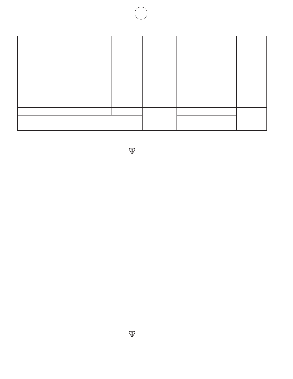
FIGURE 1
MODEL NO.
BTU/HR. RATING
NORMAL
MOUNTING
POSITION
CLEARANCES TO COMBUSTIBLES
GAS
NATURAL PROPANE TOP SIDES BACK BELOW
4030** 30,000 30,000 Horiz.-45° 30” 30” 30” 54”
4040* 40,000 40,000 Horiz.-45° 34” 30” 30” 68”
8050** 50,000 50,000 Horiz.-45° 36” 30” 30” 78”
8060* 60,000 60,000 Horiz.-45° 40” 30” 30” 84”
8070** 70,000 – Horiz.-45° 40” 30” 30” 84”
9080** 80,000 80,000 Horiz.-45° 46” 40” 40” 104”
9090** 90,000 90,000 Horiz.-45° 46” 46” 46” 114”
9100S* 100,000 100,000 Horiz.-45° 48” 46” 46” 118”
9100** 100,000 100,000 Horiz.-45° 44” 40” 40” 104”
9120* 120,000 120,000 Horiz.-45° 46” 46” 46” 114”
9140** 140,000 – Horiz.-45° 16” 46” 46” 114”
edition,orFigure1;thelargerdimensionofANSI/NFPA
No. 409 or Figure 1 is to be used. In Canada refer to
CCA B149-1-M91 and B149.2.
WARNING: MAINTAIN CLEARANCES AS SHOWN
IN FIGURE 1 OR ON HEATER NAMEPLATE, IN GARAGE
INSTALLATIONS WHERE PARKED VEHICLES ARE DI-
RECTLY BELOW THE HEATER.
3. SUSPENSION
Heater has four mounting holes, two on each end, for
attaching rod or angle iron brackets and shall be safely
andadequatelyxedinpositionindependentofgas
and electric supply lines. Refer to Figures 4, 5, and 7 on
pages 13 and 14 for recommended suspensions.
4. GAS SUPPLY
Provide adequate gas supply for rated input of each
heater using American Standard Installation of gas
piping and gas appliances in building ANSI/223. 1a/
NFPA54 Pamphlet, Table C-3 shows capacity of pipe of
different diameters and lengths in cubic feet per hour
for Natural Gas with pressure drop of 0.3 inches specify
gravityof0.60.ForliqueedPetroleumGas(LP)capac-
ity refer to Table C-3 and C-15 of the same pamphlet.
For recommended heater gas connection refer to
Figure No. 5, Page 15. In Canada refer to Can 1-B149.1
and B149.2, and CSA sto. B63.
If gas lines are to be pressure tested with compressed
air, disconnect each heater to prevent control damage
and cap outlets. After reconnecting all heaters, purge
gas lines of air and check all connections for leaks us-
ing soap solution.
WARNING: DO NOT USE MATCH OR OTHER
FLAME FOR LEAK TESTING.
5. GAS PRESSURE
Whenahigherthanthemaximumrecommended
gas pressure is being maintained at the main gas line,
*High Intensity Heaters are only sold as 4040, 8060, 9100S, and 9120
**Differentmodelnumbersareachievedbyusingsupplementaloricesincludedwithheaterstochangeheatoutput.
4
Enerco Group, Inc. |Gas-Fired Infra-Red Space Heaters OperatingInstructionsandOwner’sManual
a separate regulator must be installed ahead of the
heater.RefertoFigure2formaximumallowablepres-
sure for stated model and gas.
See heater rating plate for minimum gas supply pres-
sure “For the Purpose of Input Adjustment”
On a multiple heater installation it may be possible to
use one large capacity regulator or an individual regula-
tor for each heater. Nevertheless, it is recommended
practice to make the entire pipe system a loop. Contact
your local representative or the factory for proper gas
pressure reducing design stage.
WARNING: DO NOT EXCEED ½ P.S.I. INLET PRES-
SURE TO HEATERS SHOWN IN FIGURES 1 AND 2
6. ELECTRICAL
Allexternalwiringmustbeinaccordancewiththe
existingelectricalcode.Usewiringdiagramfurnished
with heater. Be sure electric supply characteristics
match those called for on the name plate. The unit
must be electrically grounded in accordance with the
National Electrical Code, ANSI/NFPA70, latest revision.
In Canada refer to Canadian electrical code CSA C22.1
7. THERMOSTAT & LOCATION
Make sure that the electrical characteristics of the
thermostat match those of the heater controls. For best
results thermostat should be positioned 5 ft. above
floor where air can circulate freely around it. DO NOT
MOUNT directly to cold-side wall, in direct drafts or
directly beneath the infra-red heater.
8. VENTILATION
a.Theminimumintakeandexhaustairopeningsshallpro-
vide for not less than 400 CFM for every 100,000 BTU
inputexceptthattheinltrationareamaybeincluded
intheintakearea.Theexhaustfanmustbeinterlocked
withtheheaterthermostat.Ifapowerexhaustfan
is used, it should be controlled by the thermostat or
humidistat
b.Wherenatural(gravity)ventilationisprovidedfor
exhaust,theopeningsmustbedistributedabovethe
heaters(preferablyatthepeakoftheroof)andthe
areas of openings shall not be less than 300 square
inches for every 100,000 BTU input.
9. OPERATIONS
Upon completion of electrical wiring, gas piping and
purging of gas lines to heaters, refer to the lighting
instruction plate attached to heater for proper lighting
procedure.
10. CLEANING INFORMATION
Blow out Venturi and burner face with compressed
air(25#max.pressure);alsocleanorices(seeFigure
2forcorrectsizedrill).Fordetailedmaintenanceand
cleaning instructions contact your local representative
or factory.
WARNING: GASKET BINDER MATERIAL USED
IN THIS HEATER ASSEMBLY WILL TEMPORARILY EMIT
ANODORAND/ORVAPOR.USEVENTILATION(aOR
b)ANDTHISCONDITIONWILLCLEARUPINAPPROXI-
MATELY 20 MINUTES AND WILL NOT REOCCUR.
WARNING: DO NOT ATTEMPT TO IGNITE THE
PILOT BY HAND ON HEATERS EQUIPPED WITH AUTO-
MATIC SPARK IGNITION.
WARNING: THE STATE OF CALIFORNIA REQUIRES
THE FOLLOWING WARNING: COMBUSTION BY-PROD-
UCTS PRODUCED WHEN USING THIS PRODUCT CON-
TAIN CARBON MONOXIDE, A CHEMICAL KNOWN TO
THE STATE OF CALIFORNIA TO CAUSE CANCER AND
BIRTHDEFECTS(OROTHERREPRODUCTIVEHARM).
NOTE: USE LATEST EDITION FOR ALL ANSI STAN-
DARD AND CANADIAN STANDARDS.
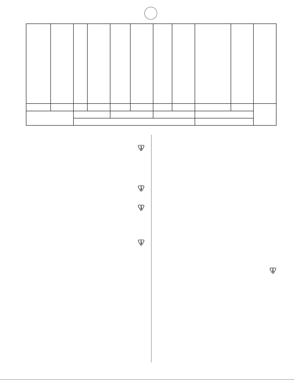
FIGURE 2
MODEL
NO.
BTU/HR. RATING GASSUPPLYPRESSURE(W.C.)
ORIFICE SIZE
GAS MIN. MAX. MANIFOLD
NATURAL PROPANE NAT. L.P. NAT. L.P. NAT. L.P. NAT. L.P.
4030 30,000 30,000 6.6” 11” 14” 14” 5.6” 10” 43 52
4040 40,000 40,000 6.8” 11” 14” 14” 5.8” 10” 37 49
8050 50,000 50,000 7.0” 11” 14” 14” 4.3” 10” 30 45
8060 60,000 60,000 7.0” 11” 14” 14” 5.8” 10” 29 43
8070 70,000 – 7.0” – 14” – 6.0” – 28 –
9080 80,000 80,000 7.0” 11” 14” 14” 5.8” 10” 37 49
9090 90,000 90,000 7.0” 11” 14” 14” 5.0” 10” 32 47
9100S 100,000 100,000 7.0” 11” 14” 14” 5.0” 10” 31 46
9100 100,000 100,000 7.0” 11” 14” 14” 4.3” 10” 30 45
9120 120,000 120,000 7.0” 11” 14” 14” 5.8” 10” 29 43
9140 140,000 – 7.0” – 14” – 5.5” – 28 –
5
OperatingInstructionsandOwner’sManualEnerco Group, Inc. | Gas-Fired Infra-Red Space Heaters
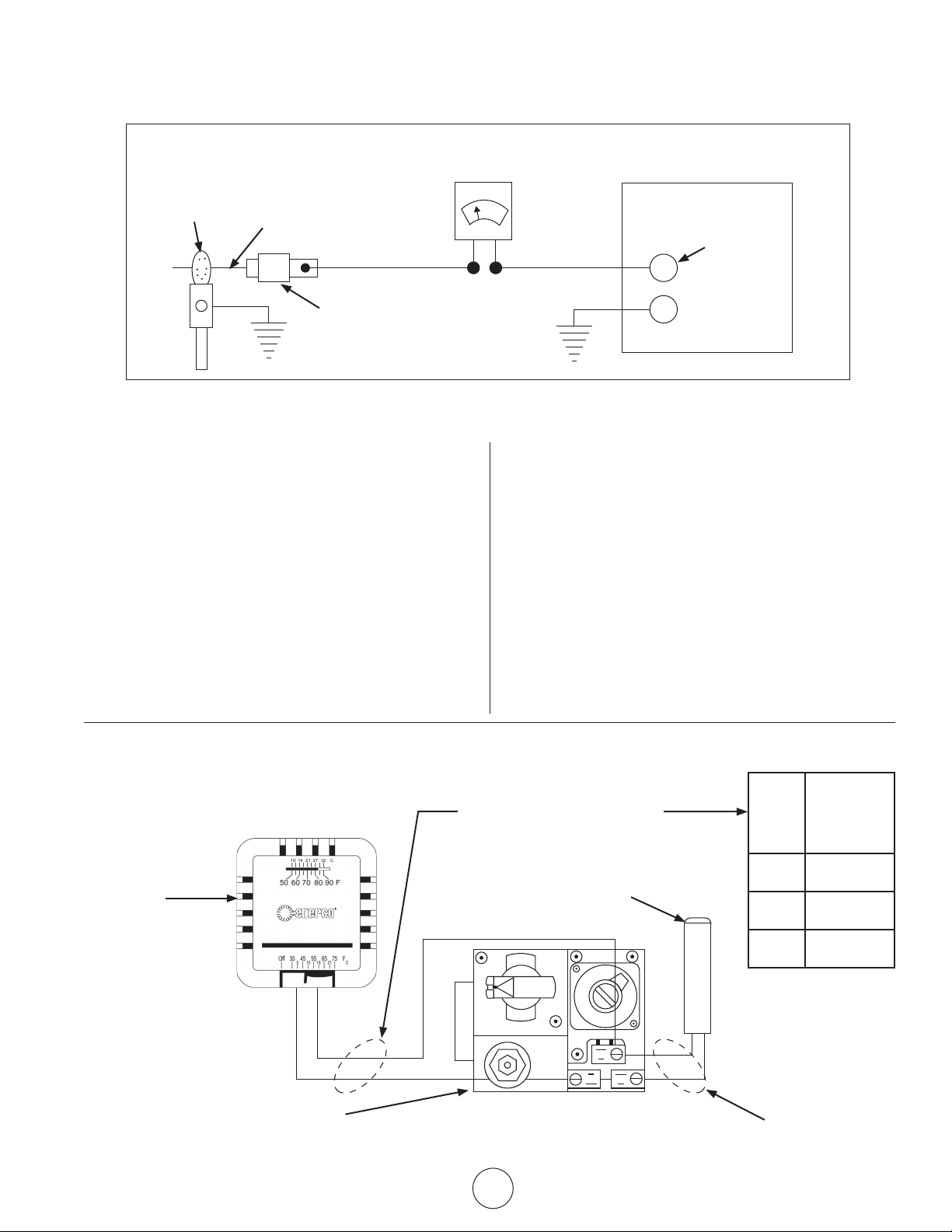
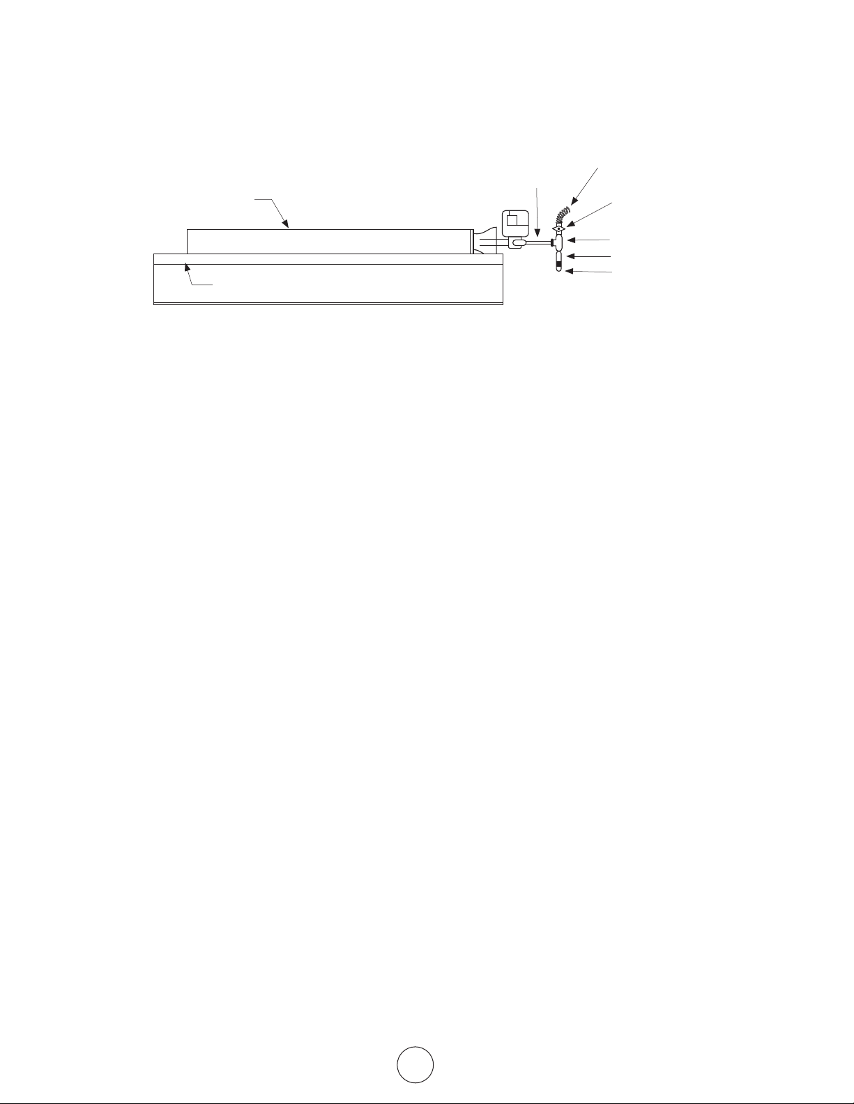
CONNECTION DIAGRAM FOR FLAME ROD CURRENT
FOR FLAME RECTIFICATION SYSTEMS (DSP-5, A5)
MEANS OF PROVING ADEQUATE GROUNDING AREA
The proper flame-rod-to-ground-area ratio cannot
alwaysbedeterminedbyvisualexaminationorphysical
measurement. A positive means of checking the instal-
lation is the measurement of the flame rod current
underactualringconditions.Itisdenitelyrecom-
mended that the installer measure the current flow be-
tween the lead of the flame rod unit and the terminal
inthecontrolterminalboard(seeFigure3).Measure
the current with a DC Microammeter or equal. We
recommend a steady output of .9 microamperes or
more. A steady flow of current in this amount under
actualringconditionswillgenerallyindicateadequate
grounding of the pilot flame.
NOTE:
1. Read all control data sheet supplied with this heater.
2. Check flame rod for any contact to heater parts. Flame
rod must be free of any contact to heater. Contact with
heater will short circuit flame rod.
3. Cracked porcelain on flame rod will short circuit sensor.
Replace flame rod.
Figure 3 – Using a microammeter to prove adequate grounding area.
Gas
Flame
Flame
Rod
Flame
Rod Assy.
Microammeter
Control
Terminal For
Flame Rod
Loadwire
G
THERMOSTAT
Thermostat
Powerpile Thermocouple
Honeywell Q313A
Factory wired
Powerpile Gas Valve – Honeywell VS820
WIRE
SIZES
MAXIMUM
LENGTH
OF WIRE
CABLE
NO 18 15 FEET
NO 16 30 FEET
NO 14 50 FEET
CAUTION TO INSTALLER
NEVER CONNECT POWERPILE
GAS VALVE OR THERMOSTAT
TO LINE VOLTAGE OR A
TRANSFORMER.
NOTE Donotexceedthe
maximumlengthslistedinthe
table when wiring between the
Thermostat and Gas Valve with
cable not supplied by HEAT STAR.
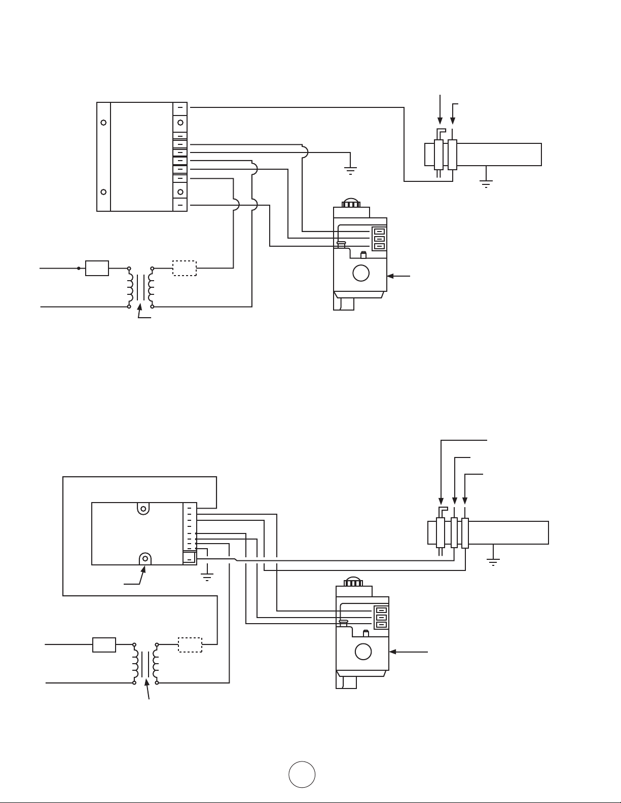
CONNECTION DIAGRAM
6
Enerco Group, Inc. |Gas-Fired Infra-Red Space Heaters OperatingInstructionsandOwner’sManual
SP715A
IGN
SP745
PV
GND
TR
PV/MV
TH
MV
LOGIC BOX
THERMOSTAT NOT
BY HEAT STAR
120 VAC
24 VOLT
THERMOSTAT
OPTIONAL
24 VAC
TRANSFORMER(SHIPPEDLOOSE)
COMBINED LOAD: 1.5 AMP.
PILOT BURNER
SPARK ELECTRODE /
FLAME SENSOR
MAIN BURNER
PV
PV/MV
MV
GAS VALVE
VR8204
A5 CONNECTION
DIAGRAM
REF. B2984-1
TH
PV
SENSE
EJ
MV
MV/PV
TR
GND
IGN
LOGIC BOX
THERMOSTAT NOT
BY HEAT STAR
120 VAC
24 VOLT
THERMOSTAT
OPTIONAL
24 VAC
TRANSFORMER(SHIPPEDLOOSE)
COMBINED LOAD: 1.5 AMP
PILOT BURNER
SPARK ELECTRODE
FLAME SENSOR
MAIN BURNER
PV
PV/MV
MV
GAS VALVE
VR8204
NDSP-5 CONNECTION
DIAGRAM
REF. A2983-1
7
OperatingInstructionsandOwner’sManualEnerco Group, Inc. | Gas-Fired Infra-Red Space Heaters
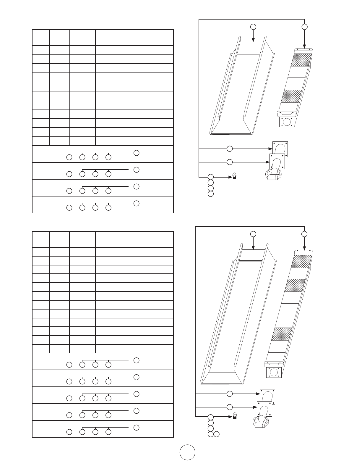
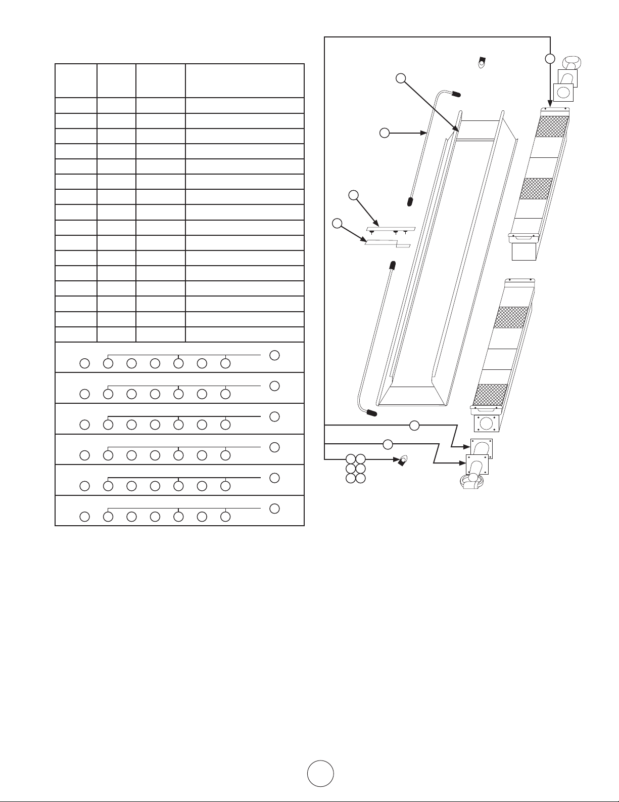
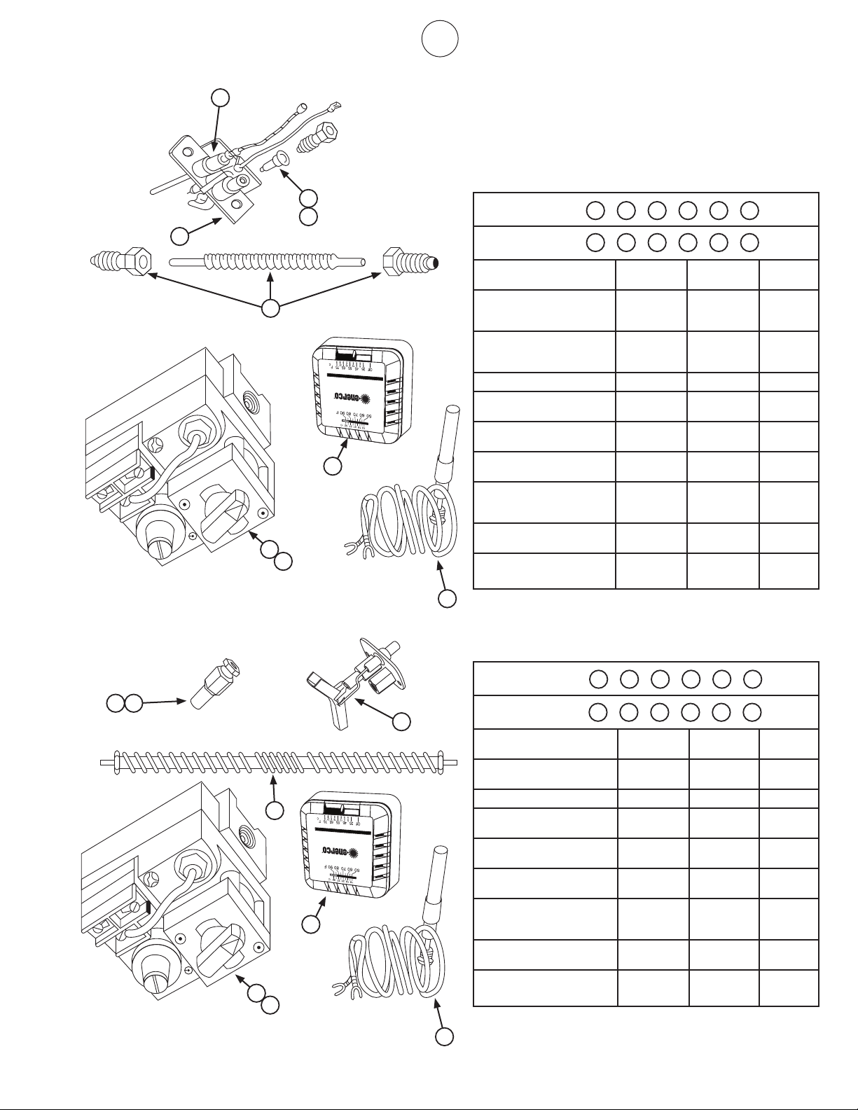
Replacement Parts List For Heaters
4000 Series Models / Less Control
Item
No.
No.
Req’d.
Stock
No.
Description
1 1 00435 A Reflector Assembly
2 1 02523 A Burner Assembly
3 1 03397 P Venturi
4
5 1 05437 Orice–Br.N.G.4040
6 1 05443 Orice–Br.N.G.4030
7 1 05449 Orice–Br.L.P.4040
8 1 05452 Orice–Br.L.P.4030
9 1 12366 Gasket – Venturi
10
11
1 3 5 9
4040 Nat. Gas
2
or
1 3 6 9
4040 Nat. Gas
2
or
1 3 7 9
4040 Propane
2
or
1 3 8 9
4040 Propane
2
or
Replacement Parts List For Heaters
8000 Series Models / Less Control
Item
No.
No.
Req’d.
Stock No. Description
1 1 00442 A Reflector Assembly
2 1 02524 A Burner Assembly
3 1 03421 P Venturi
4
5 1 05428 Orice–Br.N.G.8070
6 1 05429 Orice–Br.N.G.8060
7 1 05430 Orice–Br.N.G.8050
8 1 05443 Orice–Br.L.P.8060
9 1 05445 Orice–Br.L.P.8050
10 1 12366 Gasket – Venturi
11
12
1 3 5 10
8070 Nat. Gas
2
or
1 3 6 10
8060 Nat. Gas
2
or
1 3 7 10
8050 Nat. Gas
2
or
1 3 8 10
8060 Propane
2
or
1 3 9 10
8050 Propane
2
or
5
6
7
8
1 2
9
3
5
6
7
8 9
1 2
10
3
8
Enerco Group, Inc. |Gas-Fired Infra-Red Space Heaters OperatingInstructionsandOwner’sManual
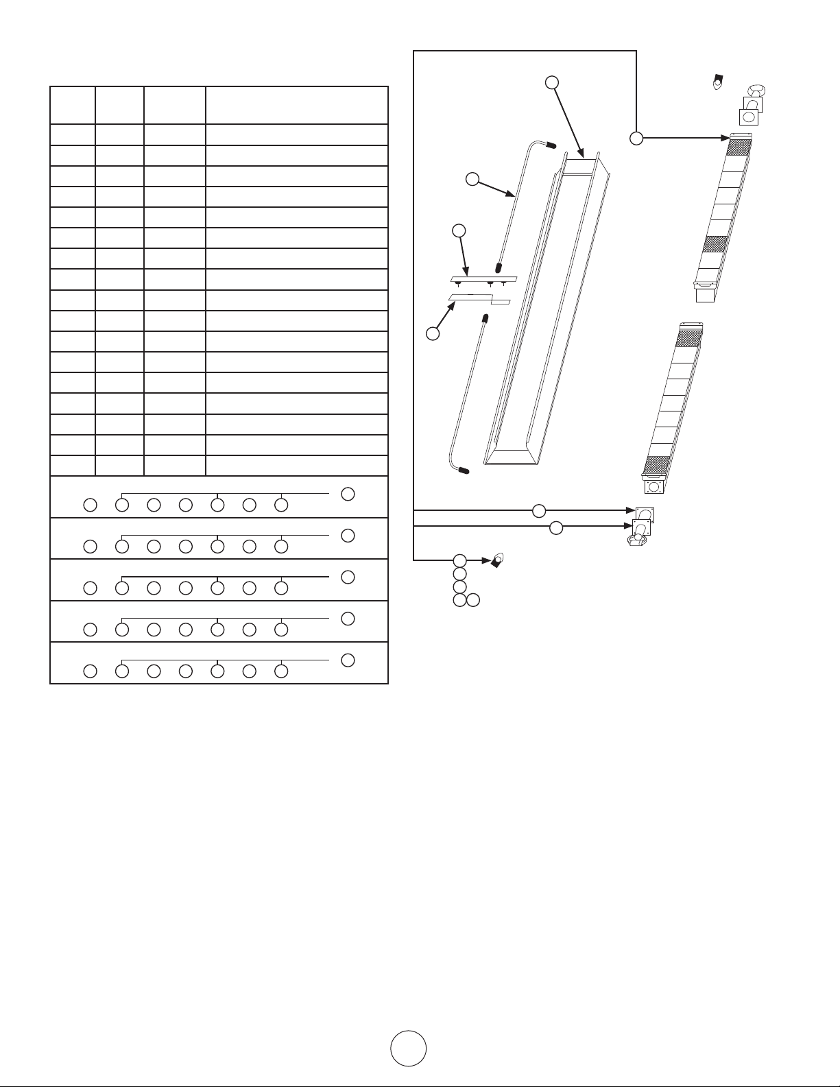
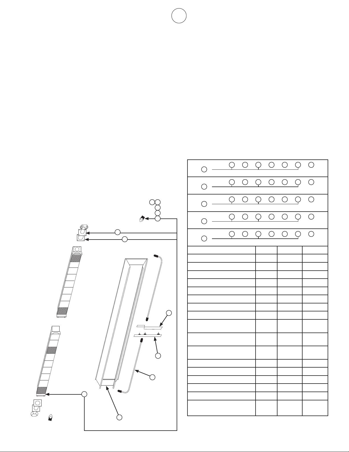
Replacement Parts List For Heaters
9000 Series Models / Less Control
Item
No.
No.
Req’d.
Stock No. Description
1 1 00444 A Reflector Assembly
2 2 02694 Burner Assembly
3 2 03421 P Venturi
4
5
6 2 05428 Orice–Br.N.G.9140
7 2 05429 Orice–Br.N.G.9120
8 2 05430 Orice–Br.N.G.9100
9 2 05443 Orice–Br.L.P.9120
10 2 05445 Orice–Br.L.P.9100
11 2 06396 Manifold Assembly
12 2 12366 Gasket – Venturi
13
14 1 14639 Center Saddle Bracket
15 1 11 3 81 CenterSupportAss’y
16
17
9140 Nat. Gas
1 3
12
6
1411 15
2
or
9120 Nat. Gas
1 3
12
7
1411 15
2
or
9100 Nat. Gas
1 3
12
8
1411 15
2
or
9120 Propane
1 3
12
9
1411 15
2
or
9100 Propane
1 3
12
10
1411 15
2
or
1
11
15
14
7
8
9 10
12
6
3
2
9
OperatingInstructionsandOwner’sManualEnerco Group, Inc. | Gas-Fired Infra-Red Space Heaters
Replacement Parts List For Heaters
9100S Series Models / Less Control
Item No.
No.
Req’d.
Stock No. Description
1 1 00443 A Reflector Assembly
2 2 02508 A Burner Assembly
3 2 03421 P Venturi
4
5
6 2 05431 Orice–Br.N.G.9100S
7 2 05432 Orice–Br.N.G.9090
8 2 05437 Orice–Br.N.G.9080
9 2 05446 Orice–Br.L.P.9100S
10 2 05447 Orice–Br.L.P.9090
11 2 05449 Orice–Br.L.P.9080
12 2 06398 Manifold Assembly
13 2 12366 Gasket – Venturi
14
15 1 14639 Center Saddle Bracket
16 1 11 3 81 Center Support Assembly
9100S Nat. Gas
1 3
13
6
1512 16
2
or
9090 Nat. Gas
1 3
13
7
1512 16
2
or
9080 Nat. Gas
1 3
13
8
1512 16
2
or
9100S Propane
1 3
13
9
1512 16
2
or
9090 Propane
1 3
13
10
1512 16
2
or
9080 Propane
1 3
13
11
1512 16
2
or
15
12
1
6 7
8 9
10 11
2
16
3
13
10
Enerco Group, Inc. |Gas-Fired Infra-Red Space Heaters OperatingInstructionsandOwner’sManual
1
3
2
5
1
3
2
or
4
8
6
7
10
9
9
5
4
8
6
7
10
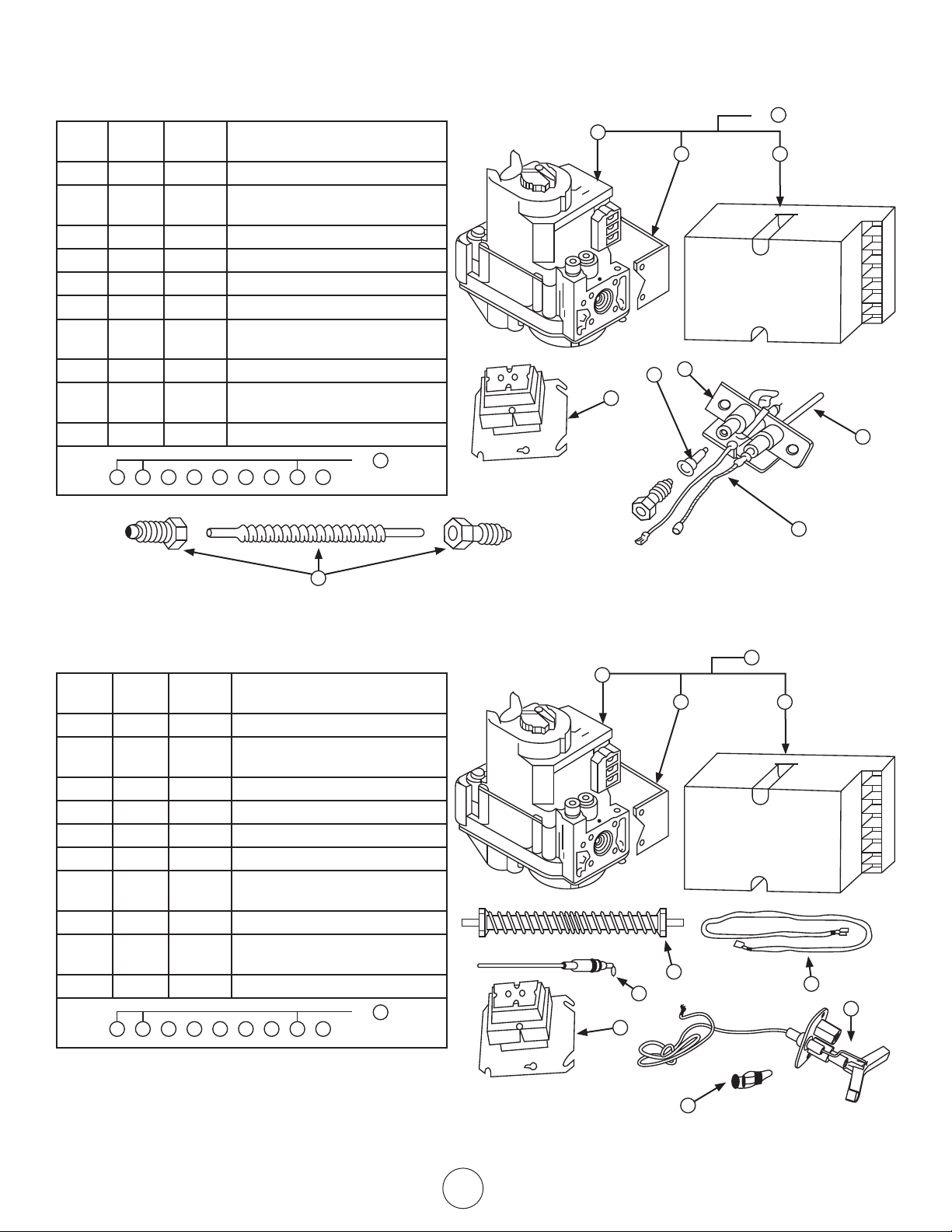
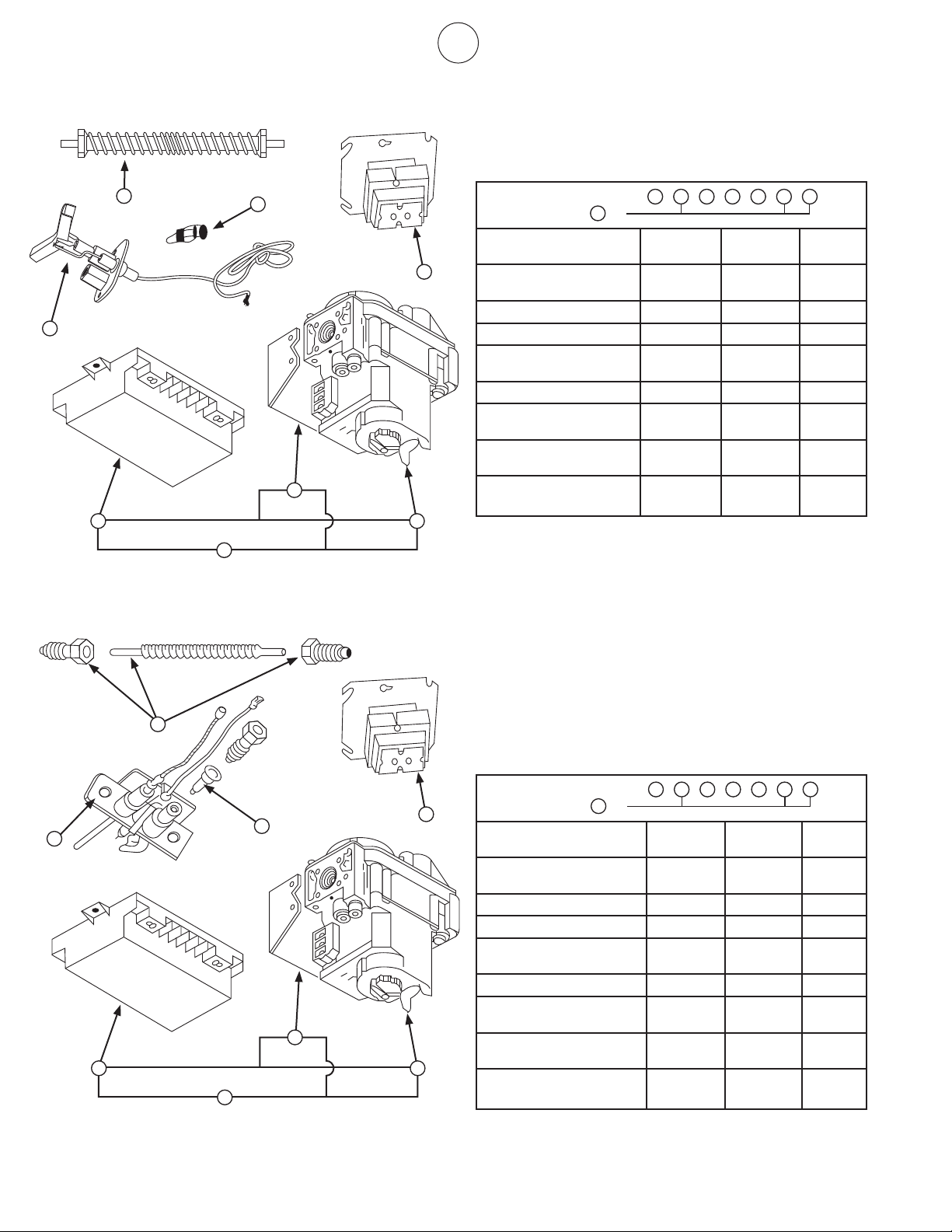
FOR HEAT STAR SERIES 4000, 8000
REPLACEMENT PARTS LIST FOR CONTROL
SYSTEM SUFFIX NDSP-5
ITEM
NO.
NO.
REQ’D
STOCK
NO.
DESCRIPTION
1 1 00028 IGNITIONCONTROL#SP715A
2 1 00037 GAS VALVE DSP-5/VR8204A2001/
SWC
3 1 00228 CONTROL ASSY. NDSP-5
4 1 05573 ORIFICE PILOT NG.
5 1 08353 TRANSFORMER 40VA
6 1 09374 PROBE T/C 1 5/32” LONG
7 1 09375 PROBE LEAD 4000, 8000, 9000
HTRS.
8 1 11403 PILOT BURNER ASSY.
9 1 14606 BRACKET MTG. SP715A RS.L. &
HON.V.
10 1 16425 FLEX PILOT TUBE W/FITTINGS
NDSP-5
2
or
1 2 4 5 6 7 8 9 10
FOR HEAT STAR SERIES 9000, 9000S
REPLACEMENT PARTS LIST FOR CONTROL
SYSTEM SUFFIX NDSP-5
ITEM
NO.
NO.
REQ’D
STOCK
NO.
DESCRIPTION
1 1 00028 IGNITIONCONTROL#SP715A
2 1 00037
GAS VALVE DSP-5/VR8204A2001/
SWC
3 1 00228 CONTROL ASSY. NDSP-5
4 1 05383 ORIFICE PILOT – NG
5 1 08353 TRANSFORMER 40VA
6 1 09374 PROBE T/C 1 5/32” LONG
7 1 09375
PROBE LEAD 4000, 8000, 9000
HTRS.
8 1 113 85 PILOT BURNER ASSY.
9 1 14606
BRACKET MTG. SP715A RS.L. &
HON.V.
10 1 16425 FLEX PILOT TUBE W/FITTINGS
NDSP-5
2
or
1 2 4 5 6 7 8 9 10
11
OperatingInstructionsandOwner’sManualEnerco Group, Inc. | Gas-Fired Infra-Red Space Heaters
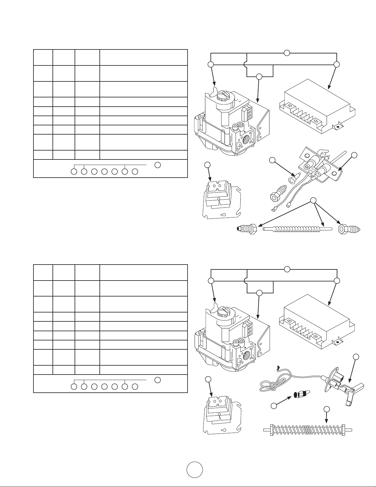
FOR HEAT STAR SERIES 9000, 9000S
REPLACEMENT PARTS LIST FOR CONTROL
SYSTEM SUFFIX LA5
ITEM
NO.
NO.
REQ’D
STOCK
NO.
DESCRIPTION
1 1 00036
GAS VALVE A5/VR8204A2092/11”
WC
2 1 00039
CONTROL LOGIC /A5/
#SP745NL36005
3 1 00329 CONTROL ASSY. LA5
4 1 05384 ORIFICE PILOT – LP
5 1 08353 TRANSFORMER 40VA
6 1 11 3 8 5 PILOT BURNER ASSY.
7 1 14615
BRACKET MTG. A5, 745RS.L. &
HON.V.
8 1 16425 FLEX PILOT TUBE W/FITTINGS
LA5
3
or
1 2 4 5 6 7 8
FOR HEAT STAR SERIES 4000, 8000
REPLACEMENT PARTS LIST FOR CONTROL
SYSTEM SUFFIX LA5
ITEM
NO.
NO.
REQ’D
STOCK
NO.
DESCRIPTION
1 1 00036
GAS VALVE A5/VR8204A2092/11”
WC
2 1 00039
CONTROL LOGIC /A5/
#SP745NL36005
3 1 00329 CONTROL ASSY. LA5
4 1 05577 ORIFICE PILOT – LP
5 1 08353 TRANSFORMER 40VA
6 1 11407 PILOT BURNER ASSY.
7 1 14615
BRACKET MTG. A5, 745RS.L. &
HON.V.
8 1 16425 FLEX PILOT TUBE W/FITTINGS
LA5
3
or
1 2 4 5 6 7 8
1 2
3
7
4
8
5
6
8
5
6
1
2
3
7
4

12
Enerco Group, Inc. |Gas-Fired Infra-Red Space Heaters OperatingInstructionsandOwner’sManual
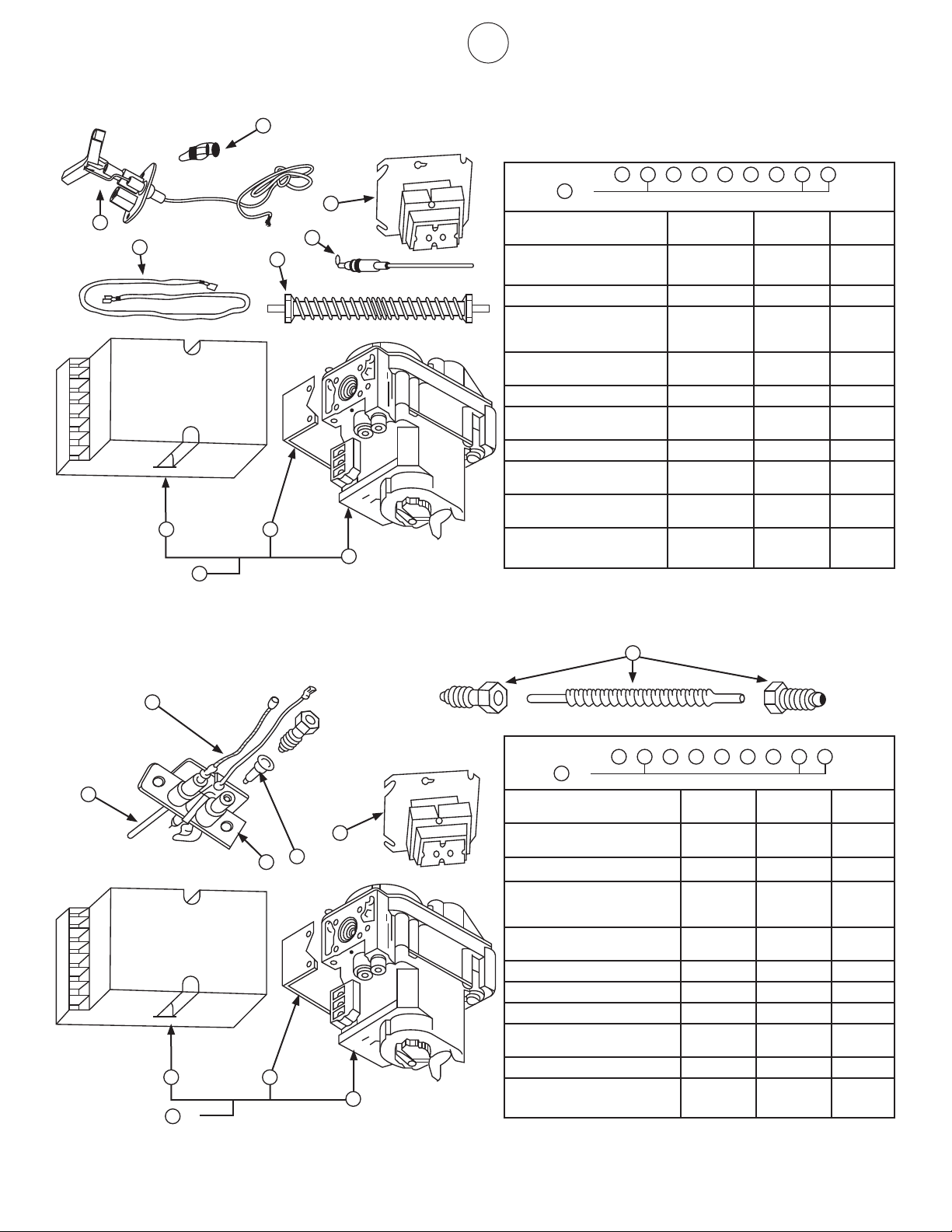
FOR HEAT STAR SERIES 9000, 9000S
REPLACEMENT PARTS LIST FOR
CONTROL SYSTEM SUFFIX NPP, LPP
ITEM
NO.
NO.
REQ’D
STOCK
NO.
DESCRIPTION
1 1 00024
COMB.GASVALVE(PP)NG.
1/2x1/2NPT
2 1 00025
COMB.GASVALVE(PP)LP.1/2x1/2
NPT
3 1 05384 ORIFICE PILOT LP
4 1 05383 ORIFICE PILOT NG
5 1 09360 THERMOCOUPLE PP HONEYWELL
6 1 10367 THERMOSTAT “PP” HEAT STAR
7 1 11 3 8 5 PILOT BURNER-9000HTR
8 1 16425 FLEX PILOT TUBE WITH FITTINGS
NPP
1 4 5 6 7 8
LPP
2 3 5 6 7 8
FOR HEAT STAR SERIES 4000, 8000
REPLACEMENT PARTS LIST FOR
CONTROL SYSTEM SUFFIX NPP, LPP
ITEM
NO.
NO.
REQ’D
STOCK
NO.
DESCRIPTION
1 1 00024
COMB.GASVALVE(PP)NG.
1/2x1/2NPT
2 1 00025
COMB.GASVALVE(PP)LP.1/2x1/2
NPT
3 1 05577 ORIFICE PILOT LP
4 1 05573 ORIFICE PILOT NG
5 1 09360 THERMOCOUPLE PP HONEYWELL
6 1 10367 THERMOSTAT “PP” HEAT STAR
7 1 11405 PILOT-PP-4K, 8K HTR NG
7 1 11408 PILOT-PP-4K, 8K HTR LP
8 1 16425 FLEX PILOT TUBE WITH FITTINGS
NPP
1 4 5 6 7 8
LPP
2 3 5 6 7 8
NOTE: 1 – WHEN ORDERING SPARE PARTS ALWAYS GIVE HEATER
MODEL NO., STOCK NO., SERIAL NO., AND TYPE OR
GAS USED.
2 – WHEN DISASSEMBLING PARTS FROM HEATER FOR RE-
PAIR, CAREFULLY NOTE ORIENTATION OF PARTS, AND
THEN REVERSE PROCEDURE WHEN ASSEMBLING.
1
4
5
6
7
8
2
3
1
5
3
6
2
8
4
5
7
13
OperatingInstructionsandOwner’sManualEnerco Group, Inc. | Gas-Fired Infra-Red Space Heaters
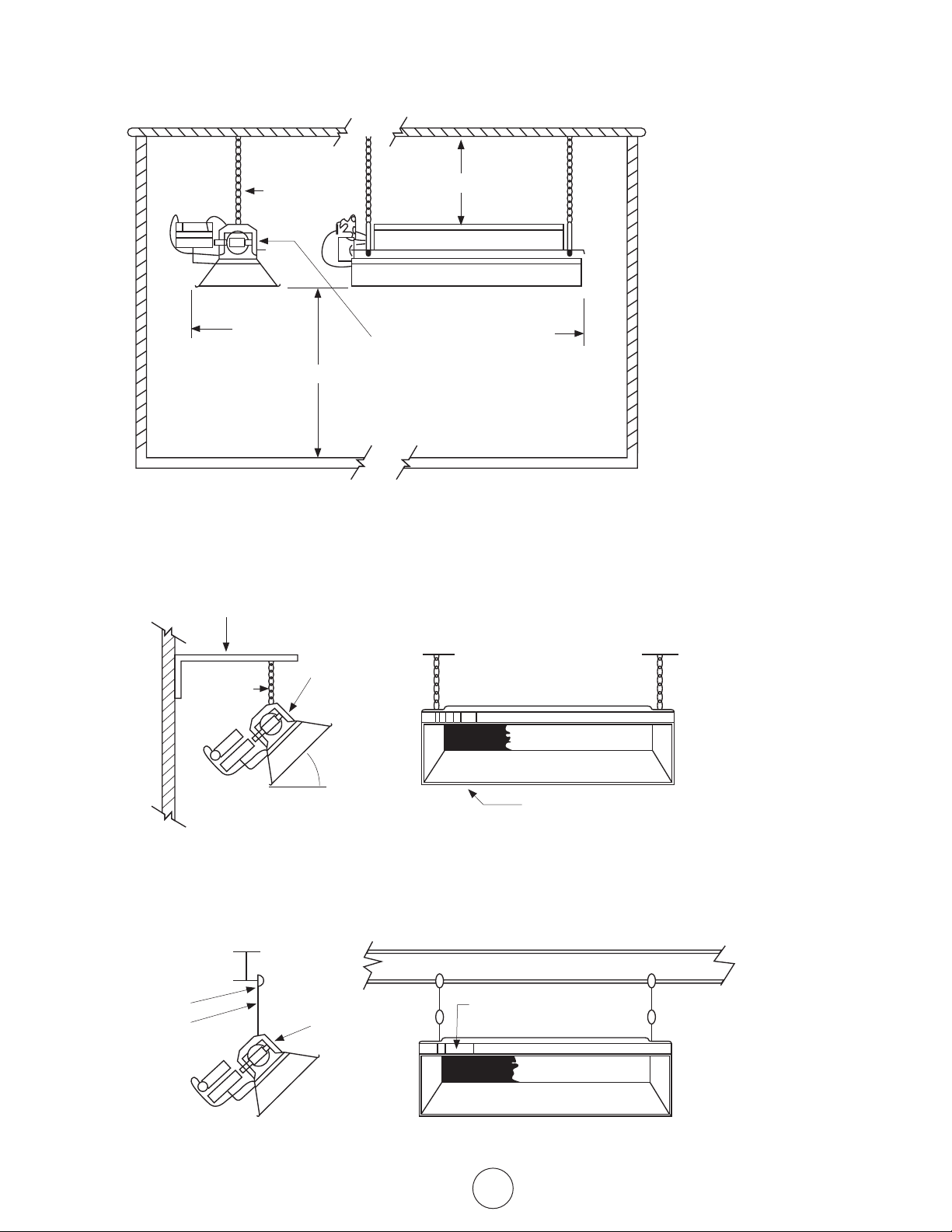
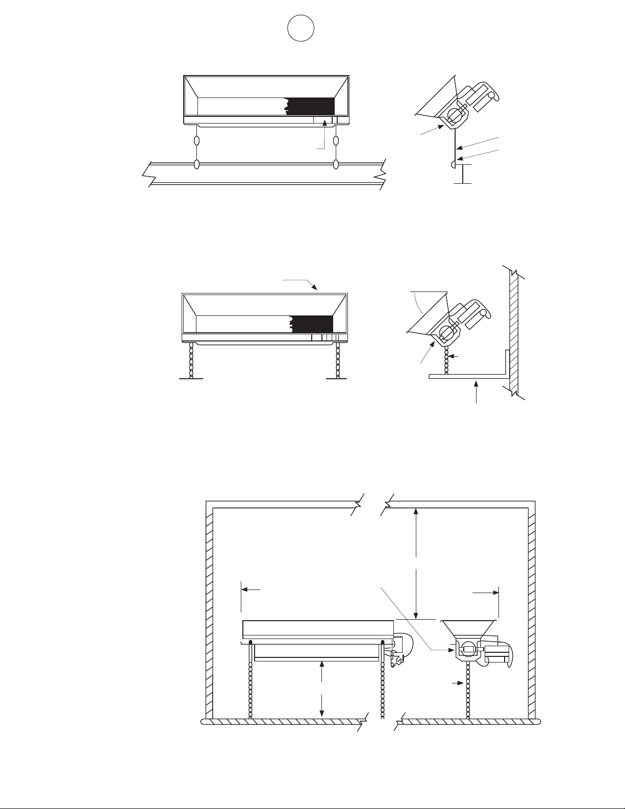
SUGGESTED HANGING METHOD
MODEL: 4000, 8000, 9000, MH40
TYPICAL BEAM MOUNT
FIGURE 4
CEILING
SIDE
WALL
FLOOR
HORIZONTAL MOUNT
BACK
SEE INSTALLATION INSTRUCTIONS FOR
DETAILED CLEARANCES INFORMATION
CLEARANCES TO COMBUSTIBLES
BELOW
TOP
BEAM CLAMP
THREADED ROD
WHEN ANGLE MOUNTING
ELEVATE ONLY DESIGNATED
SIDE OF HEATER
FIGURE 5
ANGLE IRON
SEE CHAIN KIT
#17374OR
THREADED ROD
FROM
HORIZONTAL
MAXIMUM
45°
TYPICAL WALL MOUNT
HEATER SIDE REFLECTOR MUST
BE PARALLEL TO THE FLOOR
MOUNTING
SEE CHAIN
KIT#17374
OR THREAD-
ED ROD
F114581 HANGING
BRACKET KIT
F114581 HANGING
BRACKET KIT
OR CHAIN
KIT 17374
RECOMMEND USING
HEATER HANGING
BRACKET F114581
14
Enerco Group, Inc. |Gas-Fired Infra-Red Space Heaters OperatingInstructionsandOwner’sManual
FIGURE 6
LOW PRESSURE, MAIN GAS LINE
SEE FIGURE 2 FOR PROPER INLET PRESSURES
FOR HIGHER PRESSURES THAN SHOWN ABOVE
CONTACT FACTORY FOR PROPER REGULATOR
ON THREADED PIPES USE A PIPE COMPOUND WHICH
IS RESISTANT TO THE ACTION OF ALL GASES
MUST BE RESISTANT TO PROPANE
TYPICAL LOW PRESSURE
STANDARD INSTALLATION
HEATER
MOUNTING HOLES-4 REQ’D
SIDE VIEW
½ PSI MAX.
SHUT-OFF VALVE
TEE
DRIP LEG
CAP
HIGH ALTITUDE OPERATION
Please contact the factory for a detailed High Altitude 1.
ConversionKittosuityourspecicneed.
1.1 Be prepared to answer factory questions regard-
ing: Type of fuel for the proposed appliance con-
version,gaspressureavailableatsite,andspecic
altitude at site.
“The conversion shall be carried out by a manufac-2.
turer’sauthorizedrepresentative,inaccordancewith
the requirements of the manufacturer, provincial or
territorial authorities having jurisdiction and in accor-
dance with their requirements.”
High Altitude Conversion Kits will include high 3.
altitude rating plate with stamped data, necessary
oricesorburnerasrequiredforspecicneedand
additional installation instructions.
In Canada, Heater installations at High Altitudes shall 4.
comply with the applicable construction provisions of
thecurrentstandardCAN1-2.17,gasredappliances
for use at high altitudes.
RIGID OR FLEXIBLE GAS
LINE TO HEATER
PIPE NIPPLE

15
OperatingInstructionsandOwner’sManualEnerco Group, Inc. | Gas-Fired Infra-Red Space Heaters
THIS PAGE INTENTIONALLY
LEFT BLANK
16
Enerco Group, Inc. |Gas-Fired Infra-Red Space Heaters OperatingInstructionsandOwner’sManual
WARNING: USEONLYMANUFACTURER’SREPLACEMENTPARTS.USE
OF ANY OTHER PARTS COULD CAUSE INJURY OR DEATH. REPLACEMENT PARTS
ARE ONLY AVAILABLE DIRECT FROM THE FACTORY AND MUST BE INSTALLED BY
A QUALIFIED SERVICE AGENCY.
PARTS ORDERING INFORMATION:
PURCHASING: Accessories may be purchased at any Mr. Heater/HeatStar local dealer
or direct from the factory
FOR INFORMATION REGARDING SERVICE
PleasecallToll-Free800-251-0001•www.enerco-mrheater.com
Ourofcehoursare8:30AM–5:00PM,EST,MondaythroughFriday.
Email to: techservice@enerco-mrheater.com
Please include the model number, date of purchase, and description of problem in all
communication.
LIMITED WARRANTY
The company warrants this product to be free from imperfections in material or workmanship,
under normal and proper use in accordance with instructions of The Company, for a period of
one year from the date of delivery to the buyer. The Company, at its option, will repair or replace
products returned by the buyer to the factory, transportation prepaid within said one year period
and found by the Company to have imperfections in material or workmanship.
Pro-rated 10-year warranty on the burner assembly only.
If a part is damaged or missing, call our Technical Support Department at 800-251-0001.
Address any Warranty Claims to the Service Department, Enerco Group, Inc., 4560 W. 160th St.,
Cleveland, Ohio 44135. Include your name, address and telephone number and include details
concerning the claim. Also, supply us with the purchase date and the name and address of the
dealer from whom you purchased our product.
TheforegoingisthefullextentoftheresponsibilityoftheCompany.Therearenoother
warranties,expressorimplied.Specicallythereisnowarrantyoftnessforaparticularpurpose
and there is no warranty of merchantability. In no event shall the Company be liable for delay
causedbyimperfections,forconsequentialdamages,orforanychargesoftheexpenseof
any nature incurred without its written consent. The cost of repair or replacement shall be the
exclusiveremedyforanybreachofwarranty.Thereisnowarrantyagainstinfringementofthe
like and no implied warranty arising from course of dealing or usage of trade. This warranty will
not apply to any product which has been repaired or altered outside of the factory in any respect
which in our judgment affects its condition or operation.
Somestatesdonotallowtheexclusionorlimitationofincidentalorconsequentialdamages,so
theabovelimitationorexclusionmaynotapplytoyou.ThisWarrantygivesyouspeciclegal
rights, and you may have other rights which vary from state to state.
Enerco Group, Inc.,
reserves the right to make changes at any time, without notice or
obligation,incolors,specications,accessories,materialsandmodels.
ENERCOGROUP,INC.,4560W.160THST.,CLEVELAND,OHIO44135•216-881-5500
Mr. Heater is a registered trademarks of Enerco Group, Inc.
© 2008, Enerco Group, Inc. All rights reserved
ANSI Z83.19b-2008/CSA 2.35-2007
®
®
18650 Rev. A 06/08
OPERATING INSTRUCTIONS AND OWNER’S MANUAL
READ INSTRUCTIONS CAREFULLY: Read and follow all
instructions. Place instructions in a safe place for future
reference. Do not allow anyone who has not read these
instructions to assemble, light, adjust or operate the heater.
HEATSTAR High-Intensity Infrared Heaters
HS4030 HS8070 HS9100
HS4040 HS9080 HS9120
HS8050 HS9090 HS9140
HS8060 HS9100S
MODELS
16
Enerco Group, Inc. | Appareils de chauffage à gaz infrarouge Guide d'utilisation et instructions de fonctionnement
AVERTISSEMENT : N'UTILISEZ QUE LES PIÈCES DE
REMPLACEMENT DU FABRICANT. L'UTILISATION D'AUTRES PIÈCES RISQUE DE
CAUSER DES BLESSURES ET LA MORT. LES PIÈCES DE REMPLACEMENT NE SONT
OFFERTES QUE PAR LE FABRICANT ET DOIVENT ÊTRE INSTALLÉES PAR UNE
ENTREPRISE SPÉCIALISÉE.
INFORMATIONS SUR LA COMMANDE DE PIÈCES :
ACHAT : on peut se procurer des accessoires auprès de tous les détaillants locaux Mr. Heater/
HeatStar ou directement du fabricant
POUR OBTENIR DES INFORMATIONS SUR LE SERVICE
Appelezsansfraisau1800251-0001•www.enerco-mrheater.com
Nos heures d'ouverture sont de 8 h 30 à 17 h HE, du lundi au vendredi.
Adressezvoscourrielsà:techservice@enerco-mrheater.com
Veuillez indiquer le numéro du modèle, la date d'achat et la description du problème dans toutes
vos communications avec nous.
GARANTIE LIMITÉE
L'entreprisegarantitceproduitcontretoutdéfautdematérieloudemain-d'œuvre,dansdes
conditions d'utilisation normales et adéquates, conformément aux instructions de l'entreprise,
pour une période de un an à compter de la date de livraison à l'acheteur. L'entreprise réparera
ou remplacera, à sa discrétion, les produits retournés port payé par l'acheteur au fabricant dans
lapériodedeunanetjugésparl'entreprisecommeprésentantdesdéfautsdematérieloude
main-d'œuvre.
Garantie au prorata de 10 ans sur le brûleur seulement.
Si une pièce est endommagée ou manquante, téléphonez à notre service de soutien technique
au1800251-0001.
Adressez toute réclamation relative à la garantie à Service Department, Enerco Group, Inc.,
4560W.160thSt.,Cleveland,Ohio44135États-Unis.Indiquezvosnom,adresseetnumérode
téléphoneainsiquelesdétailsdelaréclamation.Indiquez-nouségalementladated'achatetle
nom et l'adresse du détaillant auprès duquel vous avez acheté le produit.
Cequiesténoncéci-dessusconstituelaresponsabilitétotaledel'entreprise.Iln'existeaucune
autre garantie, expresse ou tacite. Plus précisément, il n'y a aucune garantie concernant
l'adéquation à un usage particulier ni aucune garantie concernant la qualité marchande.
En aucun cas l'entreprise ne sera tenue responsable des retards causés par des défectuosités,
ni des dommages indirects, ni des dépenses encourues sans son consentement écrit, quelle que
soit leur nature. Le coût de la réparation ou du remplacement sera le seul recours possible en
cas de violation de garantie. Il n'y a aucune garantie contre une transgression de ce genre ni
aucune garantie tacite découlant des usages du commerce ou de la façon habituelle d'échanger.
La présente garantie ne s'applique à aucun produit qui a été réparé ou modifié par d'autres
que le fabricant si cela influe de quelque façon que ce soit sur l'état de l'appareil ou son
fonctionnement,selonnotrejugement.
Certains États ou provinces ne permettent pas d'exclure ou de limiter les dommages indirects
ousubséquents.Parconséquent,leslimitationsouexclusionsci-dessusmentionnéesnevous
concernentpeut-êtrepas.Laprésentegarantievousaccordedesdroitsjuridiquesprécis,mais
vous pourriez avoir d'autres droits qui varient selon la province ou l'État.
Enerco Group Inc. se réserve le droit d'effectuer des modifications en tout temps, sans préavis
ni obligation, aux couleurs, aux spécifications, aux accessoires, aux matériaux et aux modèles.
ENERCOGROUP,INC.,4560W.160THST.,CLEVELAND,OHIO44135USA•(216)881-5500
Mr. Heater est une marque de commerce déposée d'Enerco Group Inc.
© 2008, Enerco Group, Inc. Tous droits réservés
ANSI Z83.19b-2008/CSA 2.35-2007
®
®
18650 Rév. A 06/08
GUIDE D'UTILISATION ET INSTRUCTIONS DE FONCTIONNEMENT
LISEZ SOIGNEUSEMENT LES INSTRUCTIONS. Lisez et observez
toutes les instructions. Conservez les instructions pour vous y référer
ultérieurement. Interdisez à quiconque n'ayant pas lu les présentes
instructions d'assembler, d'allumer, de régler ou de faire fonctionner
cet appareil de chauffage.
Appareils de chauffage infrarouge haute intensité HEATSTAR
HS4030 HS8070 HS9100
HS4040 HS9080 HS9120
HS8050 HS9090 HS9140
HS8060 HS9100S
MODÈLES

15
Guide d'utilisation et instructions de fonctionnementEnerco Group, Inc. | Appareils de chauffage à gaz infrarouge
CETTE PAGE EST LAISSÉE
BLANCHE INTENTIONNELLEMENT

14
Enerco Group, Inc. | Appareils de chauffage à gaz infrarouge Guide d'utilisation et instructions de fonctionnement
FIGURE 6
CONDUITE DE GAZ PRINCIPALE, BASSE PRESSION
CONSULTEZLAFIGURE2POURCONNAÎTRELESPRESSIONSD'ENTRÉEADÉQUATES
ENCASDEPRESSIONSUPÉRIEUREÀLAVALEURINDIQUÉECI-DESSUS,
COMMUNIQUEZ AVEC LE FABRICANT POUR OBTENIR LE RÉGULATEUR APPROPRIÉ
SUR LES CONDUITES FILETÉES, UTILISEZ UN COMPOSÉ À
CONDUITE RÉSISTANT À L'ACTION DE TOUS LES GAZ
DOIT ÊTRE RÉSISTANT AU PROPANE
INSTALLATION
STANDARD BASSE PRESSION
APPAREIL DE CHAUFFAGE
TROUSDEFIXATION-QUANTITÉ4
VUE DE CÔTÉ
½ PSI MAX.
ROBINET D'ARRÊT
TÉ
COLLECTEUR DE CONDENSATS
CAPUCHON
UTILISATION À HAUTE ALTITUDE
Veuillez communiquer avec le fabricant pour obtenir 1.
des renseignements détaillés sur l'ensemble de
conversion haute altitude qui convient précisément
à vos besoins.
1.1 Soyez prêt à répondre aux questions du fabricant
concernant le type de combustible utilisé avec
l'appareil converti, la pression de gaz dont on dispose
sur les lieux et l'altitude des lieux.
«Laconversiondoitêtreeffectuéeparun2.
représentant autorisé du fabricant, conformément
aux exigences du fabricant ainsi que des autorités
provincialesouterritorialesayantjuridiction.»
Les ensembles de conversion haute altitude 3.
comprennent une plaque signalétique haute altitude
portantdesdonnéesestampillées,lesajutagesoule
brûleur nécessaires selon les besoins, ainsi que des
instructions d'installation supplémentaires.
Au Canada, les installations d'appareils de chauffage 4.
à haute altitude doivent être conformes aux
dispositions pertinentes concernant la construction
qui sont données par la version en vigueur de la
normeCAN1-2.17surlesappareilsàgazpour
utilisation à haute altitude.
CONDUITE DE GAZ
RIGIDE OU FLEXIBLE
VERS L'APPAREIL DE
CHAUFFAGE
RACCORD DE
CONDUITE
13
Guide d'utilisation et instructions de fonctionnementEnerco Group, Inc. | Appareils de chauffage à gaz infrarouge
MÉTHODE DE SUSPENSION SUGGÉRÉE
MODÈLE : 4000, 8000, 9000, MH40
FIXATION TYPE À UNE POUTRE
FIGURE 4
PLAFOND
CÔTÉ
MUR
PLANCHER
FIXATION HORIZONTALE
ARRIÈRE
CONSULTEZ LES INSTRUCTIONS D'INSTALLATION POUR OBTENIR
DES RENSEIGNEMENTS DÉTAILLÉS SUR LES DISTANCES DE SÉCURITÉ
DISTANCES DES MATÉRIAUX COMBUSTIBLES
DESSOUS
DESSUS
COLLIER DE
POUTRE
TIGE FILETÉE
LORS D'UNE FIXATION EN ANGLE,
ÉLEVEZ SEULEMENT LE CÔTÉ DÉSI-
GNÉ DE L'APPAREIL DE CHAUFFAGE
FIGURE 5
CORNIÈRE
VOIR L'ENSEM-
BLEDECHAÎNE
Nº 17374 OU LA
TIGE FILETÉE
DEPUIS LE
MAXIMUM
HORIZONTAL
45 °
FIXATION MURALE TYPE
LE RÉFLECTEUR DU CÔTÉ APPAREIL
DE CHAUFFAGE DOIT ÊTRE
PARALLÈLE AU PLANCHER
FIXATION
VOIR L'ENSEMBLE
DECHAÎNE
Nº 17374
OU TIGE
FILETÉE
F114581 ENSEMBLE DE
FERRURE DE SUSPENSION
F114581 ENSEMBLE
DE FERRURE DE
SUSPENSION
OU ENSEMBLE
DECHAÎNE
17374
IL EST RECOMMAN-
DÉ D'UTILISER LA
FERRURE DE SUSPEN-
SION D'APPAREIL DE
CHAUFFAGE F114581
12
Enerco Group, Inc. | Appareils de chauffage à gaz infrarouge Guide d'utilisation et instructions de fonctionnement
APPAREILS DE CHAUFFAGE HEAT STAR DE SÉRIES 9000 ET 9000S
LISTE DE PIÈCES DE RECHANGE POUR LE SYSTÈME
DE COMMANDE À SUFFIXE NPP OU LPP
N°
D'ARTICLE
QUANTITÉ
NÉCESSAIRE
NUMÉRO DE
RÉFÉRENCE
DESCRIPTION
1 1 00024
ROBINETDEGAZCOMBINÉ(PP)
GAZ NATUREL 1/2 x 1/2 NPT
2 1 00025
ROBINET DE GAZ COMBINÉ
(PP)GAZDEPÉTROLELIQUÉFIÉ
1/2 x 1/2 NPT
3 1 05384
AJUTAGEVEILLEUSEGAZDE
PÉTROLE LIQUÉFIÉ
4 1 05383
AJUTAGEVEILLEUSEGAZ
NATUREL
5 1 09360
THERMOCOUPLE PP
HONEYWELL
6 1 10367 THERMOSTAT«PP»HEATSTAR
7 1 11 3 8 5
BRÛLEURVEILLEUSE-APPAREIL
DE CHAUFFAGE 9000
8 1 16425
TUBE FLEXIBLE DE VEILLEUSE
AVEC RACCORDS
NPP
LPP
APPAREILS DE CHAUFFAGE HEAT STAR DE SÉRIES 4000 ET 8000
LISTE DE PIÈCES DE RECHANGE POUR LE SYSTÈME
DE COMMANDE À SUFFIXE NPP OU LPP
N°
D'ARTICLE
QUANTITÉ
NÉCESSAIRE
NUMÉRO DE
RÉFÉRENCE
DESCRIPTION
1 1 00024
ROBINETDEGAZCOMBINÉ(PP)
GAZ NATUREL 1/2 x 1/2 NPT
2 1 00025
ROBINET DE GAZ COMBINÉ
(PP)GAZDEPÉTROLELIQUÉFIÉ
1/2 x 1/2 NPT
3 1 05577
AJUTAGEVEILLEUSEGAZDE
PÉTROLE LIQUÉFIÉ
4 1 05573
AJUTAGEVEILLEUSEGAZ
NATUREL
5 1 09360
THERMOCOUPLE PP
HONEYWELL
6 1 10367 THERMOSTAT«PP»HEATSTAR
7 1 11405
VEILLEUSEPP-APPAREILSDE
CHAUFFAGE 4000 ET 8000 GAZ
NATUREL
7 1 11408
VEILLEUSEPP-APPAREILSDE
CHAUFFAGE 4000 ET 8000 GAZ
DE PÉTROLE LIQUÉFIÉ
8 1 16425
TUBE FLEXIBLE DE VEILLEUSE
AVEC RACCORDS
NPP
LPP
REMARQUE : 1 – LORSQUE VOUS COMMANDEZ DES PIÈCES DE
RECHANGE,INDIQUEZTOUJOURSLENUMÉRODE
MODÈLE, LE NUMÉRO DE RÉFÉRENCE ET LE NUMÉRO DE
SÉRIE DE L'APPAREIL DE CHAUFFAGE, AINSI QUE LE TYPE
DE GAZ UTILISÉ.
2 – LORSQUE VOUS DÉMONTEZ DES PIÈCES DE L'APPAREIL
DE CHAUFFAGE EN VUE D'UNE RÉPARATION, NOTEZ
SOIGNEUSEMENT L'ORIENTATION DES PIÈCES, PUIS SUIVEZ
LA PROCÉDURE INVERSE POUR REFAIRE LE MONTAGE.
1
4
5
6
7
8
2
3
1
5
3
6
2
8
4
5
7
1 4 5 6 7 8
2 3 5 6 7 8
1 4 5 6 7 8
2 3 5 6 7 8
11
Guide d'utilisation et instructions de fonctionnementEnerco Group, Inc. | Appareils de chauffage à gaz infrarouge
APPAREILS DE CHAUFFAGE HEAT STAR DE SÉRIES 9000 ET 9000S
LISTE DE PIÈCES DE RECHANGE POUR LE SYSTÈME
DE COMMANDE À SUFFIXE LA5
N°
D'ARTICLE
QUANTITÉ
NÉCESSAIRE
NUMÉRO DE
RÉFÉRENCE
DESCRIPTION
1 1 00036
ROBINET DE GAZ A5/
VR8204A2092/11” WC
2 1 00039
LOGIQUE DE COMMANDE /
A5/#SP745NL36005
3 1 00329 COMMANDE LA5
4 1 05384
AJUTAGEVEILLEUSE–GAZ
DE PÉTROLE LIQUÉFIÉ
5 1 08353 TRANSFORMATEUR 40 VA
6 1 11 3 8 5 BRÛLEUR VEILLEUSE
7 1 14615
FERRURE DE MONTAGE A5,
745RS.L. ET HON.V.
8 1 16425
TUBE FLEXIBLE DE VEILLEUSE
AVEC RACCORDS
LA5
APPAREILS DE CHAUFFAGE HEAT STAR DE SÉRIES 4000 ET 8000
LISTE DE PIÈCES DE RECHANGE POUR LE SYSTÈME
DE COMMANDE À SUFFIXE LA5
N°
D'ARTICLE
QUANTITÉ
NÉCESSAIRE
NUMÉRO DE
RÉFÉRENCE
DESCRIPTION
1 1 00036
ROBINET DE GAZ A5/
VR8204A2092/11” WC
2 1 00039
LOGIQUE DE COMMANDE /
A5/#SP745NL36005
3 1 00329 COMMANDE LA5
4 1 05577
AJUTAGEVEILLEUSE–GAZ
DE PÉTROLE LIQUÉFIÉ
5 1 08353 TRANSFORMATEUR 40 VA
6 1 11407 BRÛLEUR VEILLEUSE
7 1 14615
FERRURE DE MONTAGE A5,
745RS.L. ET HON.V.
8 1 16425
TUBE FLEXIBLE DE VEILLEUSE
AVEC RACCORDS
LA5
1 2
3
7
4
8
5
6
8
5
6
1
2
3
7
4
3
ou
1 2 4 5 6 7 8
3
ou
1 2 4 5 6 7 8
10
Enerco Group, Inc. | Appareils de chauffage à gaz infrarouge Guide d'utilisation et instructions de fonctionnement
1
3
2
5
1
3
2
4
8
6
7
10
9
9
5
4
8
6
7
10
APPAREILS DE CHAUFFAGE HEAT STAR DE SÉRIES 4000 ET 8000
LISTE DE PIÈCES DE RECHANGE POUR LE SYSTÈME
DE COMMANDE À SUFFIXE NDSP-5
N°
D'ARTICLE
QUANTITÉ
NÉCESSAIRE
NUMÉRO DE
RÉFÉRENCE
DESCRIPTION
1 1 00028 COMMANDED'ALLUMAGE#SP715A
2 1 00037 ROBINETDEGAZDSP-5/
VR8204A2001/SWC
3 1 00228 COMMANDENDSP-5
4 1 05573 AJUTAGEVEILLEUSEGAZNATUREL
5 1 08353 TRANSFORMATEUR 40 VA
6 1 09374 SONDE THERMOCOUPLE DE
1 5/32 PO DE LONGUEUR
7 1 09375 CONDUCTEUR DE SONDE POUR
APPAREILS DE CHAUFFAGE 4000,
8000 ET 9000
8 1 11403 BRÛLEUR VEILLEUSE
9 1 14606 FERRURE DE MONTAGE SP715A RS.L.
ET HON.V.
10 1 16425 TUBE FLEXIBLE DE VEILLEUSE AVEC
RACCORDS
NDSP-5
APPAREILS DE CHAUFFAGE HEAT STAR DE SÉRIES 9000 ET 9000S
LISTE DE PIÈCES DE RECHANGE POUR LE SYSTÈME
DE COMMANDE À SUFFIXE NDSP-5
N°
D'ARTICLE
QUANTITÉ
NÉCESSAIRE
NUMÉRO DE
RÉFÉRENCE
DESCRIPTION
1 1 00028
COMMANDE D'ALLUMAGE
#SP715A
2 1 00037
ROBINETDEGAZDSP-5/
VR8204A2001/SWC
3 1 00228 COMMANDENDSP-5
4 1 05383
AJUTAGEVEILLEUSEGAZ
NATUREL
5 1 08353 TRANSFORMATEUR 40 VA
6 1 09374
SONDE THERMOCOUPLE DE
1 5/32 PO DE LONGUEUR
7 1 09375
CONDUCTEUR DE SONDE POUR
APPAREILS DE CHAUFFAGE 4000,
8000 ET 9000
8 1 11 3 8 5 BRÛLEUR VEILLEUSE
9 1 14606
FERRURE DE MONTAGE SP715A
RS.L. ET HON.V.
10 1 16425
TUBE FLEXIBLE DE VEILLEUSE
AVEC RACCORDS
NDSP-5
2
ou
1 2 4 5 6 7 8 9 10
2
ou
1 2 4 5 6 7 8 9 10

9
Guide d'utilisation et instructions de fonctionnementEnerco Group, Inc. | Appareils de chauffage à gaz infrarouge
Liste de pièces de rechange pour les appareils de chauffage
des modèles de série 9100S / moins la commande
Nº
d'article
Quantité
nécessaire
Nº de
référence
Description
1 1 00443 A Réflecteur
2 2 02508 A Brûleur
3 2 03421 P Venturi
4
5
6 2 05431 Ajutage–brûleurgaznaturel
9100S
7 2 05432 Ajutage–brûleurgaznaturel
9090
8 2 05437 Ajutage–brûleurgaznaturel
9080
9 2 05446 Ajutage–brûleurL.P.9100S
10 2 05447 Ajutage–brûleurL.P.9090
11 2 05449 Ajutage–brûleurL.P.9080
12 2 06398 Collecteur
13 2 12366 Jointd'étanchéité–venturi
14
15 1 14639 Ferrure centrale
16 1 11 3 81 Support central
9100S gaz naturel
1 3
13
6
1512 16
2
ou
9090 gaz naturel
1 3
13
7
1512 16
2
ou
9080 gaz naturel
1 3
13
8
1512 16
2
ou
9100S propane
1 3
13
9
1512 16
2
ou
9090 propane
1 3
13
10
1512 16
2
ou
9080 propane
1 3
13
11
1512 16
2
ou
15
12
1
6 7
8 9
10 11
2
16
3
13
8
Enerco Group, Inc. | Appareils de chauffage à gaz infrarouge Guide d'utilisation et instructions de fonctionnement
Liste de pièces de rechange pour les appareils de chauffage
des modèles de série 9000 / moins la commande
Nº d'article
Quantité
nécessaire
Nº de
référence
Description
1 1 00444 A Réflecteur
2 2 02694 Brûleur
3 2 03421 P Venturi
4
5
6 2 05428
Ajutage–brûleurgaznaturel
9140
7 2 05429
Ajutage–brûleurgaznaturel
912 0
8 2 05430
Ajutage–brûleurgaznaturel
9100
9 2 05443 Ajutage–brûleurL.P.9120
10 2 05445 Ajutage–brûleurL.P.9100
11 2 06396 Collecteur
12 2 12366 Jointd'étanchéité–venturi
13
14 1 14639 Ferrure centrale
15 1 113 81 Support central
16
17
9140 gaz naturel
1 3
12
6
1411 15
2
ou
9120 gaz naturel
1 3
12
7
1411 15
2
ou
9100 gaz naturel
1 3
12
8
1411 15
2
ou
9120 propane
1 3
12
9
1411 15
2
ou
9100 propane
1 3
12
10
1411 15
2
ou
1
11
15
14
7
8
9 10
12
6
3
2

7
Guide d'utilisation et instructions de fonctionnementEnerco Group, Inc. | Appareils de chauffage à gaz infrarouge
Liste de pièces de rechange pour les appareils de
chauffage des modèles de série 4000 / moins la commande
Nº d'article
Quantité
nécessaire
Nº de
référence
Description
1 1 00435 A Réflecteur
2 1 02523 A Brûleur
3 1 03397 P Venturi
4
5 1 05437 Ajutage–brûleurgaznaturel
4040
6 1 05443 Ajutage–brûleurgaznaturel
4030
7 1 05449 Ajutage–brûleurL.P.4040
8 1 05452 Ajutage–brûleurL.P.4030
9 1 12366 Jointd'étanchéité–venturi
10
11
1 3 5 9
4040 gaz naturel
2
ou
1 3 6 9
4040 gaz naturel
2
ou
1 3 7 9
4040 propane
2
ou
1 3 8 9
4040 propane
2
ou
Liste de pièces de rechange pour les appareils de
chauffage des modèles de série 8000 / moins la commande
Nº d'article
Quantité
nécessaire
Nº de
référence
Description
1 1 00442 A Réflecteur
2 1 02524 A Brûleur
3 1 03421 P Venturi
4
5 1 05428 Ajutage–brûleurgaznaturel8070
6 1 05429 Ajutage–brûleurgaznaturel8060
7 1 05430 Ajutage–brûleurgaznaturel8050
8 1 05443 Ajutage–brûleurL.P.8060
9 1 05445 Ajutage–brûleurL.P.8050
10 1 12366 Jointd'étanchéité–venturi
11
12
1 3 5 10
8070 gaz naturel
2
ou
1 3 6 10
8060 gaz naturel
2
ou
1 3 7 10
8050 gaz naturel
2
ou
1 3 8 10
8060 propane
2
ou
1 3 9 10
8050 propane
2
ou
5
6
7
8
1 2
9
3
5
6
7
8 9
1 2
10
3

6
Enerco Group, Inc. | Appareils de chauffage à gaz infrarouge Guide d'utilisation et instructions de fonctionnement
SP715A
ALLUMAGE
SP745
ROBINET VEILLEUSE
MISE À LA TERRE
TRANSFORMATEUR
ROBINET VEILLEUSE/ROBINET PRINCIPAL
THERMOSTAT
ROBINET PRINCIPAL
BOÎTIERDE
LOGIQUE
THERMOSTAT NON
FOURNI PAR HEAT STAR
120 V C.A.
THERMOSTAT
24 VOLTS
EN OPTION
24 V C.A.
TRANSFORMATEUR
(EXPÉDIÉNONFIXÉ)
CHARGE COMBINÉE : 1,5 A
BRÛLEUR VEILLEUSE
ÉLECTRODE / DÉTEC-
TEUR DE FLAMME
BRÛLEUR
PRINCIPAL
ROBINET VEILLEUSE
ROBINET VEILLEUSE/ROBINET PRINCIPAL
ROBINET PRINCIPAL
ROBINET DE GAZ
VR8204
DIAGRAMME DE
RACCORDEMENT A5
RÉF.B2984-1
THERMOSTAT
ROBINET VEILLEUSE
DÉTECTION
ÉJECTION
ROBINET PRINCIPAL
ROBINET PRINCIPAL/ROBINET VEILLEUSE
TRANSFORMATEUR
MISE À LA TERRE
ALLUMAGE
BOÎTIERDE
LOGIQUE
THERMOSTAT NON
FOURNI PAR HEAT STAR
120 V C.A.
THERMOSTAT
24 VOLTS
EN OPTION
24 V C.A.
TRANSFORMATEUR(EXPÉDIÉNONFIXÉ)
CHARGE COMBINÉE : 1,5 A
BRÛLEUR VEILLEUSE
ÉLECTRODE
DÉTECTEUR
DE FLAMME
BRÛLEUR
PRINCIPAL
ROBINET VEILLEUSE
ROBINET VEILLEUSE/ROBINET PRINCIPAL
ROBINET PRINCIPAL
ROBINET DE GAZ
VR8204
DIAGRAMME DE
RACCORDEMENTNDSP-5
RÉF.A2983-1

5
Guide d'utilisation et instructions de fonctionnementEnerco Group, Inc. | Appareils de chauffage à gaz infrarouge
DIAGRAMME DE RACCORDEMENT POUR MESURE DU COURANT À L'ÉLECTRODE DE DÉTECTION
DE FLAMME DANS LES DISPOSITIFS DE REDRESSEMENT DU COURANT (DSP-5, A5)
COMMENT VÉRIFIER QUE LA SURFACE DE MISE À LA
TERRE EST ADÉQUATE
Iln'estpastoujourspossiblededéterminerlebonrapport
entre l'électrode de détection de flamme et la surface de
mise à la terre par un examen visuel ou une mesure physique.
Un bon moyen de vérifier l'installation consiste à mesurer
le courant à l'électrode de détection de flamme dans des
conditions réelles de combustion. Il est fortement recom-
mandé que l'installateur mesure l'intensité du courant entre le
conducteur de l'électrode de détection de flamme et la borne
surlepanneauderaccordementdelacommande(consultez
lagure3).Mesurezlecourantavecunmicroampèremètre
c.c. ou un instrument équivalent. Nous recommandons un
courant de sortie constant de 0,9 microampère ou plus. La
présence d'un courant constant d'une telle grandeur dans des
conditions réelles de combustion indique généralement une
mise à la terre adéquate de la flamme de la veilleuse.
REMARQUE :
1. Lisez toute la fiche de données de contrôle fournie avec l'appa-
reil de chauffage.
2. Vérifiez que l'électrode de détection de flamme ne touche pas
des pièces de l'appareil de chauffage. L'électrode de détection
de flamme ne doit pas entrer en contact avec l'appareil de
chauffage. Tout contact avec l'appareil de chauffage provo-
querauncourt-circuitdel'électrodededétectiondeamme.
3. De la porcelaine craquée sur l'électrode de détection de
ammeprovoquerauncourt-circuitdudétecteur.Remplacez
l'électrode de détection de flamme.
Figure 3 – Utilisation d'un microampèremètre pour vérifier que la surface de mise à la terre est adéquate.
Flamme au
gaz
Électrode de
détection de
flamme
Ensemble
d'électrode
de détection
de flamme
Microampèremètre
Commande
Borne pour fil
de charge de
l'électrode de
détection de
flamme
Mise à
la terre
THERMOSTAT
Thermostat
Thermocouple Powerpile
Honeywell Q313A
Câblé en usine
Robinet de gaz Powerpile –
Honeywell VS820
CALIBRE
DU CÂBLE
LONGUEUR
MAXIMALE
DU CÂBLE
Nº 18 15 PIEDS
Nº 16 30 PIEDS
Nº 14 50 PIEDS
MISE EN GARDE À L'INSTALLATEUR
NE JAMAIS CONNECTER LA SOUPAPE
DE GAZ OU LE THERMOSTAT À LA
TENSION DE LIGNE OU À UN TRANS-
FORMATEUR.
REMARQUE Ne dépassez pas les
longueurs maximales données par
le tableau lorsque vous faites le
câblage entre le thermostat et le
robinet de gaz avec du câble non
fourni par HEAT STAR.
DIAGRAMME DE RACCORDEMENT
4
Enerco Group, Inc. | Appareils de chauffage à gaz infrarouge Guide d'utilisation et instructions de fonctionnement
5. PRESSION DU GAZ
Lorsque la pression du gaz dépasse le maximum recommandé
et qu'elle est maintenue dans la conduite de gaz principale,
il est recommandé d'installer un régulateur séparé en aval de
l'appareil de chauffage. Consultez la figure 2 pour connaître
la pression maximale permise selon le modèle de l'appareil et
le gaz utilisé.
Consultez la plaque signalétique de l'appareil de chauffage
pour connaître la pression d'alimentation minimale aux fins
deréglagedelapressiond'entrée(«ForthePurposeofInput
Adjustment»).
Dans une installation à plusieurs appareils de chauffage,
il peut être possible d'utiliser un seul régulateur à grande
capacité ou un régulateur individuel pour chaque appareil.
Néanmoins, il est recommandé de créer un système de
tuyauterie en boucle. Communiquez avec votre représentant
ou avec le fabricant pour obtenir la configuration requise
pour réduire la pression du gaz.
AVERTISSEMENT : NE DÉPASSEZ PAS UNE
PRESSION D'ENTRÉE DE ½ PSI DANS LE CAS DES APPAREILS
DE CHAUFFAGE MENTIONNÉS AUX FIGURES 1 ET 2.
6. CIRCUIT ÉLECTRIQUE
Tout le câblage extérieur doit être conforme au code
de l'électricité en vigueur. Utilisez le schéma de câblage
fourniavecl'appareildechauffage.Assurez-vousqueles
caractéristiques de l'alimentation électrique correspondent
à celles qui sont indiquées sur la plaque signalétique.
L'appareil doit être mis à la terre conformément à la plus
récente révision du National Electrical Code, ANSI/NFPA70.
Au Canada, consultez le Code canadien de l'électricité
CSA C22.1.
7. THERMOSTAT ET EMPLACEMENT D'INSTALLATION
Assurez-vousquelescaractéristiquesélectriquesdu
thermostat correspondent à celles des commandes de
l'appareil de chauffage. Pour obtenir des résultats optimaux,
lethermostatdoitêtreinstalléàaumoins1,52m(5pi)
au-dessusduplancheroùl'airpeutcirculerlibrementautour.
NE MONTEZ PAS le thermostat directement sur un mur
froid, dans un courant d'air ou directement sous l'appareil
de chauffage infrarouge.
8. VENTILATION
a. Les orifices d'air d'admission et d'échappement minimaux
fournissent pas moins de 400 pieds cubes/minute pour
chaque 100 000 BTU d'entrée sauf que la zone d'infiltration
peut être incluse dans la zone d'admission. Le ventilateur
d'échappement peut être verrouillé avec le thermostat
de l'appareil de chauffage. Si l'on utilise un ventilateur
d'échappement autodébrayable, il doit être commandé par le
thermostat ou par l'humidostat.
b. Là où il y a un système de ventilation avec échappement par
gravité,ilestimportantderépartirlesoricesau-dessusde
l'appareildechauffage(préférablementaupointleplusélevé
delatoiture)etlesouverturesdoiventmesureraumoins
300 pouces carrés pour chaque entrée de 100 000 BTU.
9. UTILISATION
Une fois que vous avez terminé le câblage électrique,
l'installation des conduites de gaz et la purge des conduites
de gaz menant aux appareils de chauffage, consultez
la plaque des instructions d'allumage fixée à l'appareil
de chauffage pour connaître la procédure d'allumage
appropriée.
10. NETTOYAGE
Nettoyez le venturi et la face du brûleur en y soufflant de
l'aircomprimé(pressionmaximalede25#);nettoyezaussi
lesajutages(consultezlagure2pourconnaîtrelataillede
mècheàutiliser).Pourobtenirdesinstructionsd'entretien
et de nettoyage détaillées, communiquez avec votre
représentant ou avec le fabricant.
AVERTISSEMENT : LELIANTÀJOINT
D'ÉTANCHÉITÉ UTILISÉ LORS DE L'ASSEMBLAGE DE
L'APPAREIL DE CHAUFFAGE ÉMET TEMPORAIREMENT UNE
ODEUR ET/OU DES VAPEURS. SUIVEZ LA PROCÉDURE DE
VENTILATION(aOUb)ETCEPHÉNOMÈNEDISPARAÎTRAAU
BOUT DE 20 MINUTES ENVIRON ET NE SE REPRODUIRA PLUS.
AVERTISSEMENT : N'ESSAYEZ PAS D'ALLUMER
LA VEILLEUSE À LA MAIN SUR UN APPAREIL DE CHAUFFAGE
DOTÉ DE L'ALLUMAGE AUTOMATIQUE PAR ÉTINCELLE.
AVERTISSEMENT : AVERTISSEMENT DE L'ÉTAT
DE LA CALIFORNIE : L'UTILISATION DE CET APPAREIL CRÉE
DESSOUS-PRODUITSDECOMBUSTIONCONTENANT
DU MONOXYDE DE CARBONE, UN PRODUIT CHIMIQUE
RECONNU PAR L'ÉTAT DE LA CALIFORNIE COMME CAUSE DE
CANCERETD'ANOMALIESCONGÉNITALES(OUD'AUTRES
RISQUESPOURLAREPRODUCTION).
REMARQUE : UTILISEZ LES PLUS RÉCENTES
VERSIONS DE TOUTES LES NORMES ANSI ET NORMES
CANADIENNES.
FIGURE 2
MODÈLE
N°
BTU/HR CAPACITÉ NOMINALE PRESSIOND'ALIMENTATIONENGAZ(W.C.)
DIMENSION DE
L'AJUTAGE
GAZ MIN. MAX. COLLECTEUR
NATUREL PROPANE NAT. L.P. NAT. L.P. NAT. L.P. NAT. L.P.
4030 30 000 30 000 6,6 po 11 po 14 po 14 po 5,6 po 10 po 43 52
4040 40 000 40 000 6,8 po 11 po 14 po 14 po 5,8 po 10 po 37 49
8050 50 000 50 000 7,0 po 11 po 14 po 14 po 4,3 po 10 po 30 45
8060 60 000 60 000 7,0 po 11 po 14 po 14 po 5,8 po 10 po 29 43
8070 70 000 – 7,0 po – 14 po – 6,0 po – 28 –
9080 80 000 80 000 7,0 po 11 po 14 po 14 po 5,8 po 10 po 37 49
9090 90 000 90 000 7,0 po 11 po 14 po 14 po 5,0 po 10 po 32 47
9100S 100 000 100 000 7,0 po 11 po 14 po 14 po 5,0 po 10 po 31 46
9100 100 000 100 000 7,0 po 11 po 14 po 14 po 4,3 po 10 po 30 45
9120 120 000 120 000 7,0 po 11 po 14 po 14 po 5,8 po 10 po 29 43
9140 140 000 – 7,0 po – 14 po – 5,5 po – 28 –
3
Guide d'utilisation et instructions de fonctionnementEnerco Group, Inc. | Appareils de chauffage à gaz infrarouge
1. RENSEIGNEMENTS GÉNÉRAUX :
Votre appareil de chauffage est livré entièrement a.
assemblé et a été préalablement inspecté en usine pour
approuver le type de gaz utilisé et la bonne marche de
l'appareil, conformément à la plaque signalétique.
Avant de procéder à l'installation, effectuez une inspection b.
pour déceler la présence de dommages. La compagnie de
transportdoitêtreaviséedetouslesdommages;exigez
qu'une inspection soit effectuée par la compagnie de
transport. HEAT STAR vous expédiera des pièces de rechange
en échange de pièces défectueuses uniquement après
avoir reçu un rapport d'inspection signé qui témoigne de la
responsabilité de la compagnie de transport.
Ne pas tenter de faire fonctionner l'appareil de chauffage c.
avec un autre type de gaz que celui indiqué sur la plaque
signalétique.
L'installation de l'appareil de chauffage doit respecter les d.
codes du bâtiment locaux ou, en l'absence de tels codes, doit
se conformer à la norme ANSI Z223.1a/NFPA54 du National
FuelGasCode.AuCanada,consultezlescodesCan1-B146.1
et B149.2.
Ontrouveraunraccordde1/8poN.P.T.(NationalPipee.
Thread),obturéetdestinéàrecevoirunmanomètred'essai,
sur la commande de gaz de l'appareil de chauffage, ou
encore un raccord de ¼ po N.P.T. sur l'extérieur du venturi
moulé.
2. DISTANCES DE SÉCURITÉ Distances de sécurité
minimales des matériaux combustibles. (consultez
la figure 1)
Prévoyez une distance de sécurité adéquate entre les
matériauxcombustibles(consultezlagure1)etl'extrémité
de commande de l'appareil de chauffage ainsi qu'une
distanceminimaleau-dessusetsurlescôtésandes'assurer
d'une bonne alimentation en air pour la ventilation et la
combustion.
Dans le cas des garages publics, prévoyez une distance de
sécuritéminimalede8piau-dessusdusolconformément
à la norme ANSI/NFPA Nº 88 dans sa plus récente version
ou utilisez la valeur indiquée à la figure 1, selon la valeur
la plus grande des deux. Au Canada, consultez les codes
d'installationpourappareilsàgazCan1-B149.1etB149.2.
Prévoyez une distance de sécurité minimale de 10 pi du
dessous de l'appareil de chauffage au dessus de l'aile, ou
du capotage du moteur, aux endroits où des avions sont
FIGURE 1
MODÈLE N°
BTU/HR CAPACITÉ NOMINALE
POSITION
NORMALE DE
FIXATION
DISTANCES DES MATÉRIAUX COMBUSTIBLES
GAZ
NATUREL PROPANE DESSUS CÔTÉS ARRIÈRE DESSOUS
4030** 30 000 30 000 Horiz.-45° 30 po 30 po 30 po 54 po
4040* 40 000 40 000 Horiz.-45° 34 po 30 po 30 po 68 po
8050** 50 000 50 000 Horiz.-45° 36 po 30 po 30 po 78 po
8060* 60 000 60 000 Horiz.-45° 40 po 30 po 30 po 84 po
8070** 70 000 – Horiz.-45° 40 po 30 po 30 po 84 po
9080** 80 000 80 000 Horiz.-45° 46 po 40 po 40 po 104 po
9090** 90 000 90 000 Horiz.-45° 46 po 46 po 46 po 114 po
9100S* 100 000 100 000 Horiz.-45° 48 po 46 po 46 po 118 po
9100** 100 000 100 000 Horiz.-45° 44 po 40 po 40 po 104 po
9120* 120 000 120 000 Horiz.-45° 46 po 46 po 46 po 114 po
9140** 140 000 – Horiz.-45° 16 po 46 po 46 po 114 po
entreposés,etde8piau-dessusduplancherdanslesautres
parties du hangar conformément à la norme ANSI/NFPA
Nº 409 dans sa plus récente version ou utilisez la valeur
indiquée à la figure 1, selon la valeur la plus grande des deux.
AuCanada,consultezlescodesCCAB149-1-M91etB149.2.
AVERTISSEMENT : DANS LES GARAGES OÙ
DES VÉHICULES SONT STATIONNÉS DIRECTEMENT SOUS
L'APPAREIL DE CHAUFFAGE, CONSERVEZ LES DISTANCES DE
SÉCURITÉ INDIQUÉES À LA FIGURE 1 OU SUR LA PLAQUE
SIGNALÉTIQUE DE L'APPAREIL DE CHAUFFAGE.
3. SUSPENSION
L'appareil de chauffage comporte quatre trous de montage,
deux à chaque extrémité, permettant d'y attacher une
tige ou des cornières, et doit être fixé adéquatement, en
toute sécurité, à l'écart des conduites de gaz et des lignes
d'alimentation électrique. Consultez les figures 4, 5 et 7 aux
pages 13 et 14 pour connaître les méthodes de suspension
recommandées.
4. ALIMENTATION EN GAZ
Fournissez une alimentation en gaz appropriée à l'entrée
nominale de chaque appareil de chauffage, conformément
à la norme sur l'installation des conduites de gaz et des
appareils à gaz dans les immeubles, brochure ANSI/223.
1a/NFPA54.LetableauC-3decettebrochuredonnela
capacité de conduites de gaz naturel de différents diamètres
et longueurs, en pieds cubes par heure, avec une chute de
pression de 0,3 pouce et une gravité spécifique de 0,60. Pour
connaître la capacité des conduites de gaz de pétrole liquéfié
(LP),consultezlestableauxC-3etC-15delabrochure.Pour
connaître la méthode recommandée de raccordement du
gaz à l'appareil de chauffage, consultez la figure 5, page 15.
AuCanada,consultezlescodesCan1-B149.1etB149.2ainsi
que la norme CSA B63.
Si les conduites de gaz doivent être mises à l'essai avec de
l'air comprimé, débranchez chaque appareil de chauffage
pour éviter d'endommager les commandes et installez
des bouchons aux sorties. Après avoir reconnecté tous les
appareils de chauffage, vidangez l'air des conduites de gaz et
vérifiez toutes les connexions pour déceler les fuites à l'aide
d'une solution savonneuse.
AVERTISSEMENT : NE PAS UTILISER
D'ALLUMETTE NI AUCUN AUTRE TYPE DE FLAMME POUR
DÉTECTER DES FUITES.
*Les appareils de chauffage haute intensité sont vendus uniquement sous les numéros de modèle 4040, 8060, 9100S et 9120.
**D'autresnumérosdemodèlesontobtenusparl'utilisationd'ajutagessupplémentairesquel'onajouteauxappareilsdechauffagepourmodierledébitdechaleur.
2
Enerco Group, Inc. | Appareils de chauffage à gaz infrarouge Guide d'utilisation et instructions de fonctionnement
TABLE DES MATIÈRES
Renseignements généraux .................................................3
Distances de sécurité ........................................................ 3
Alimentation en gaz .......................................................... 3
Pression du gaz .................................................................4
Circuit électrique ............................................................... 4
Thermostat et emplacement d'installation ......................... 4
Ventilation ........................................................................ 4
Utilisation ......................................................................... 4
Nettoyage ......................................................................... 4
Diagramme de raccordement pour mesure du courant
à l'électrode de détection de flamme
dans les dispositifs de redressement du courant ................5
Thermostat ....................................................................... 5
Pièces de rechange ........................................................... 7
Pièces de rechange du système de commande ............... 10
AVERTISSEMENT : Une installation incorrecte, un réglage
inadéquat, une modification, une réparation ou un entretien
inappropriés peuvent causer des dommages, des blessures,
voire même la mort. Lisez les instructions d'installation,
de fonctionnement et d'entretien avant de procéder à
l'installation ou à l'entretien de cet équipement. Pour obtenir
de l'aide ou des renseignements supplémentaires, consultez
un installateur qualifié, un fournisseur de services d'entretien
ou un fournisseur de gaz.
AVERTISSEMENT : Si l'appareil de chauffage est utilisé
sans l'apport d'air frais, il peut émettre du MONOXYDE DE
CARBONE, un gaz toxique inodore. OUVREZ LA FENÊTRE
D'UN POUCE OU DEUX POUR LAISSER PÉNÉTRER L'AIR FRAIS
LORS DE L'UTILISATION DE L'APPAREIL DE CHAUFFAGE.
AVERTISSEMENT : Cet appareil de chauffage est muni
d'un SYSTÈME DE SÉCURITÉ À VEILLEUSE. NE PAS ALTÉRER
LE SYSTÈME DE SÉCURITÉ À VEILLEUSE!
AVERTISSEMENT : Si le système de chauffage s'éteint, ne
le rallumez pas tant qu'il n'y a pas d'air frais. Si le système de
chauffagen'arrêtepasdes'éteindre,faites-leréparer.Garder
le brûleur et la zone de commande propres. Ouvrez la porte
pendant 5 minutes.
Respectez les distances de sécurité indiquées à la figure 1 ou sur
la plaque signalétique de l'appareil de chauffage.
•N'UTILISEZPASD'ALLUMETTENIAUCUNAUTRETYPE
DE FLAMME POUR DÉTECTER DES FUITES.
•NEJAMAISDÉPASSER1/2LB/POUCECARRÉ(PSI)
DE PRESSION D'ADMISSION AU SYSTÈME.
DANGER :
L'empoisonnement au monoxyde de carbone peut causer
la mort.
Empoisonnement au monoxyde de carbone :
Lessignesavant-coureursd'intoxicationaumonoxyde
de carbone ressemblent aux symptômes de la grippe
accompagnés de maux de tête, d'étourdissements et
de nausée. Si vous ressentez ces maux, l'appareil de
chauffagenefonctionnepeut-êtrepascorrectement.Allez
immédiatement à l'air libre! Faites inspecter l'appareil de
chauffage. Certaines personnes sont plus affectées par le
monoxyde de carbone que d'autres. Elles comprennent les
femmes enceintes, les personnes souffrant de maladies
cardiaques, pulmonaires ou d'anémie, les personnes sous
l'influence d'alcool et celles qui se trouvent en haute altitude.
ATTENTION :
•Nejamaisconnecterlasoupapedegazoulethermostat
à la tension de ligne ou à un transformateur.
•Silacouleurinfrarougedelagrilledevientternelorsque
le système de chauffage de l'immeuble est en fonction,
consultez le fournisseur de gaz pour obtenir les dimensions
correctes des conduites d'alimentation de gaz.
•Cetappareildechauffageestréservéexclusivement
à l'usage intérieur.
REMARQUELeliantàjointd'étanchéitéutilisélors
de l'assemblage de l'appareil de chauffage émet
temporairement une odeur et/ou des vapeurs. Cette
condition disparaît en 20 minutes approximativement et par
conséquent ne se reproduit plus par la suite. Consultez la
page 4 pour connaître les procédures de ventilation.
AVERTISSEMENT DE L'ÉTAT DE LA CALIFORNIE :
AVERTISSEMENT : L'utilisation de cet appareil crée
dessous-produitsdecombustioncontenantdumonoxyde
de carbone, un produit chimique reconnu par l'État de
la Californie comme cause de cancer et d'anomalies
congénitales(oud'autresrisquespourlareproduction).

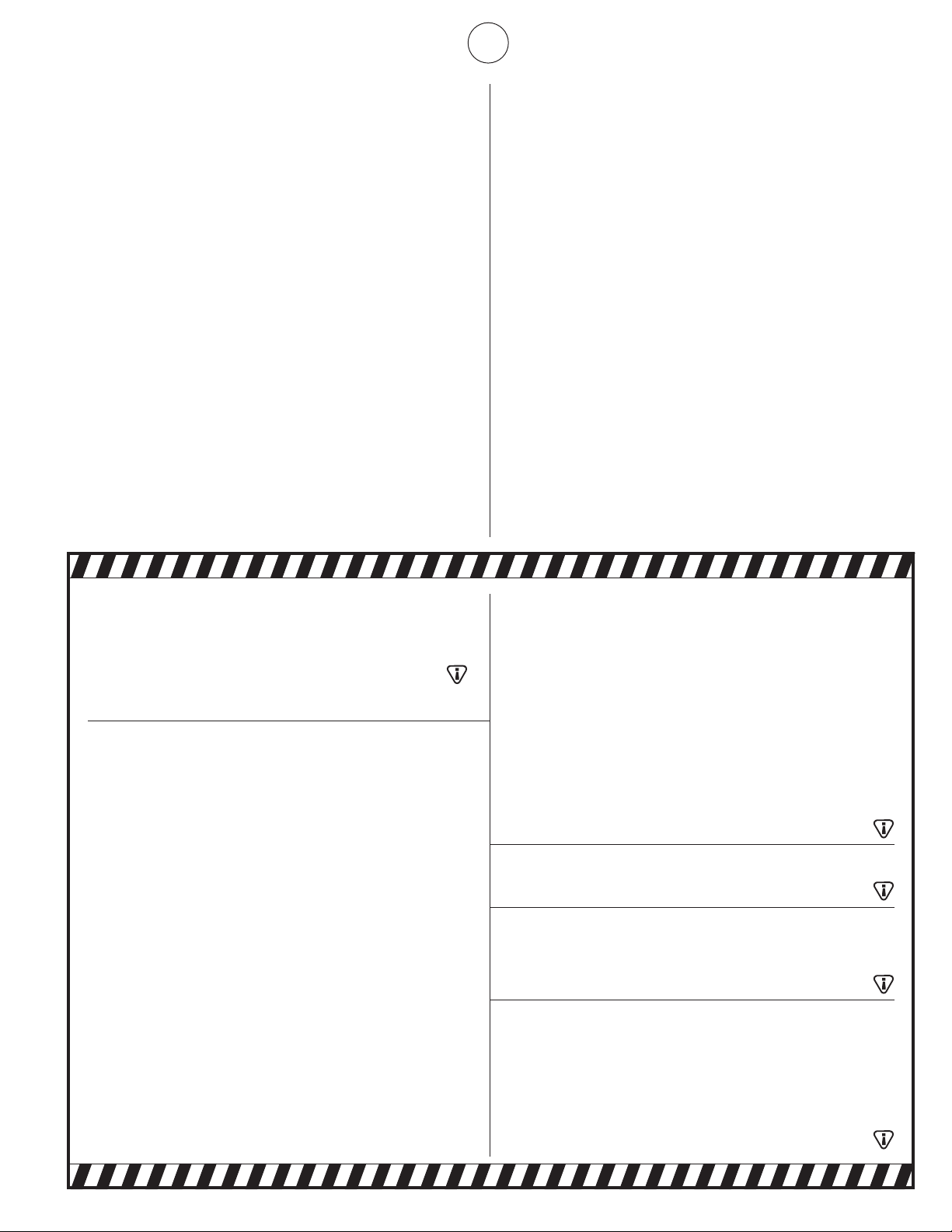
GUIDE D'UTILISATION ET INSTRUCTIONS DE FONCTIONNEMENT
LISEZ SOIGNEUSEMENT LES INSTRUCTIONS. Lisez et observez
toutes les instructions. Conservez les instructions pour vous y référer
ultérieurement. Interdisez à quiconque n'ayant pas lu les présentes
instructions d'assembler, d'allumer, de régler ou de faire fonctionner
cet appareil de chauffage.
Appareils de chauffage infrarouge haute intensité HEATSTAR
HS4040 HS9100S
HS8060 HS9120
MODÈLES
À l'installateur : rangez ce manuel avec l'appareil. Au consommateur : conservez ce manuel pour vous y référer ultérieurement.
Le fait de ne pas respecter les instructions données dans le présent
guide avec exactitude risque d'entraîner une explosion ou un incendie
causant des dommages matériels, des blessures et des pertes de vie.
AVERTISSEMENT :
– N'entreposez pas et n'utilisez pas d'essence ou d'autres liquides ou vapeurs inflammables à proximité
de ce type d'appareil.
– EN PRÉSENCE D'UNE ODEUR DE GAZ
• Coupezl'alimentationdugaz
• Netentezpasd'allumerl'appareildechauffage
• Netouchezàaucuninterrupteurélectrique;n'utilisezaucuntéléphonedansl'immeuble
• Appelezimmédiatementvotrefournisseurdegazàpartirdutéléphoned'unvoisin.
Suivez les instructions du fournisseur de gaz
• Sivousnepouvezjoindrevotrefournisseurdegaz,appelezleservicedesincendies
— L'installation et l'entretien doivent être exécutés par un installateur qualifié, par un fournisseur de services
d'entretien ou par un fournisseur de gaz.
Cet appareil de chauffage alimenté au gaz n'est pas ventilé. Il utilise l'oxygène de l'air ambiant.
Une circulation d'air adéquate doit être assurée pour la combustion et la ventilation. Consultez la page 4.
ENERCOGROUP,INC.,4560W.160THST.,CLEVELAND,OHIO44135USA•(216)916-3000
Modèles 4000 et 8000 Modèles 9000
18650 Rév. A 06/08