Loading ...
Loading ...
Loading ...

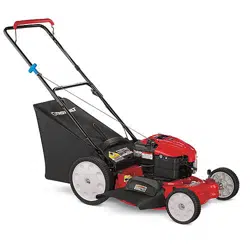
SECTION3: ASSEMBLINGYOURLAWNMOWER
RemovingUnitFromCarton
• Remove staples, break glue on top flaps, or cut
tape at carton end and open carton.
• Remove loose parts if included with unit (i.e.,
operator's manual, etc.)
• Cut along corners, lay the carton down flat, and
remove all packing material.
• Roll or slide unit out of carton and check carton
thoroughly for loose parts.
LoosePartsinCarton
• Grass Bag
• Side Discharge Chute
• Rear Wheels
• Hardware Pack
• Bottle of Oil
HardwarePack
Please identify each piece
of the hardware pack as
shown here.
BeforeAssembly
Carriage WingNut
Bolt
Before setting up your lawn mower, disconnect the
spark plug wire from the spark plug. See Figure 1.
Spark Plug
Figure 1
NOTE: Reference to right or left hand side of the mower
is observed from the operating position.
SettingUpYourLawnMower
AssemblingHandle
• Lift up and pull back on the upper handle to raise
the handle into the operating position. See Figure
2. Make certain the lower handle is seated securely
into the handle bracket assemblies.
Upper
Handle
LowerHandle
J
Handle
B
Figure 2
Make sure that carriage bolt through the upper and
lower handles on each side is properly seated.
Tighten the wing nuts. See Figure 3.
Carriage
Bolt
Tighten these
wing nuts
i
Carriage
Bolt
Figure 3
Remove hairpin clip from the outer hole of the weld
pin on each handle brackets. Using a pair of pliers,
squeeze one leg of the lower handle against the
handle bracket. Insert the hairpin clip into the inner
hole on the weld pin. Repeat on the other side. See
Figure 4.
..... ,,_,_ Carriage Bolt
Wing _ _ .... WeldPin
*Wheel not shownfor clarity .....
Figure 4
After moving the hairpin clip, insert the carriage
bolt, from the hardware pack, in the upper hole on
the handle mounting bracket and secure with
plastic wing nut from the hardware pack. See
Figure 4. Repeat on the other side.
Loading ...
Loading ...
Loading ...