Loading ...
Loading ...
Loading ...
If you havea54"mowerdeckgo directlyto page8.
All otherdecksizesusethefollowing instructions.
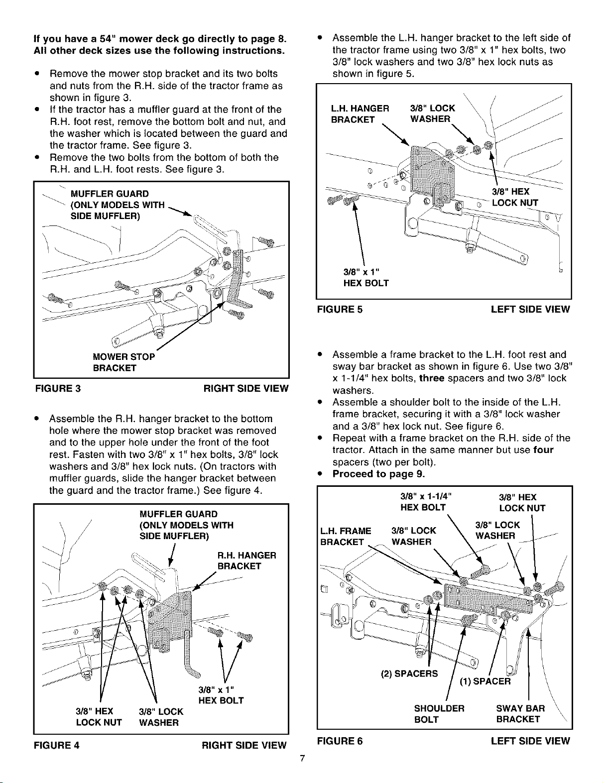
• Remove the mower stop bracket and its two bolts
and nuts from the R.H. side of the tractor frame as
shown in figure 3.
• If the tractor has a muffler guard at the front of the
R.H. foot rest, remove the bottom bolt and nut, and
the washer which is located between the guard and
the tractor frame. See figure 3.
• Remove the two bolts from the bottom of both the
R.H. and L.H. foot rests. See figure 3.
MUFFLER GUARD
SIDE MUFFLER)
• Assemble the L.H. hanger bracket to the left side of
the tractor frame using two 3/8" x 1" hex bolts, two
3/8" lock washers and two 3/8" hex lock nuts as
shown in figure 5.
'\
\
L.H. HANGER 3/8" LOCK \
BRACKET WASHER \
"-,
3/8" x 1"
HEX BOLT
FIGURE 5 LEFT SIDE VIEW
MOWER STOP
BRACKET
FIGURE 3 RIGHT SIDE VIEW
Assemble the R.H. hanger bracket to the bottom
hole where the mower stop bracket was removed
and to the upper hole under the front of the foot
rest. Fasten with two 3/8" x 1" hex bolts, 3/8" lock
washers and 3/8" hex lock nuts. (On tractors with
muffler guards, slide the hanger bracket between
the guard and the tractor frame.) See figure 4.
MUFFLER GUARD
(ONLY MODELS WITH
SIDE MUFFLER)
R.H. HANGER
BRACKET
3/8" HEX 3/8" LOCK
LOCK NUT WASHER
3/8" x 1"
HEX BOLT
• Assemble a frame bracket to the L.H. foot rest and
sway bar bracket as shown in figure 6. Use two 3/8"
x 1-1/4" hex bolts, three spacers and two 3/8" lock
washers.
• Assemble a shoulder bolt to the inside of the L.H.
frame bracket, securing it with a 3/8" lock washer
and a 3/8" hex lock nut. See figure 6.
• Repeat with a frame bracket on the R.H. side of the
tractor. Attach in the same manner but use four
spacers (two per bolt).
• Proceed to page 9.
3/8" x 1-1/4" 3/8" HEX
HEX BOLT LOCK NUT
3/8" LOCK
L,H, FRAME 3/8" LOCK WASHER
BRACKET WASHER
FIGURE 6
(2) SPACERS
(1) SPACER
SHOULDER SWAY BAR
BOLT BRACKET
LEFT SIDE VIEW
FIGURE 4 RIGHT SIDE VIEW
7
Loading ...
Loading ...
Loading ...