Loading ...
Loading ...
Loading ...
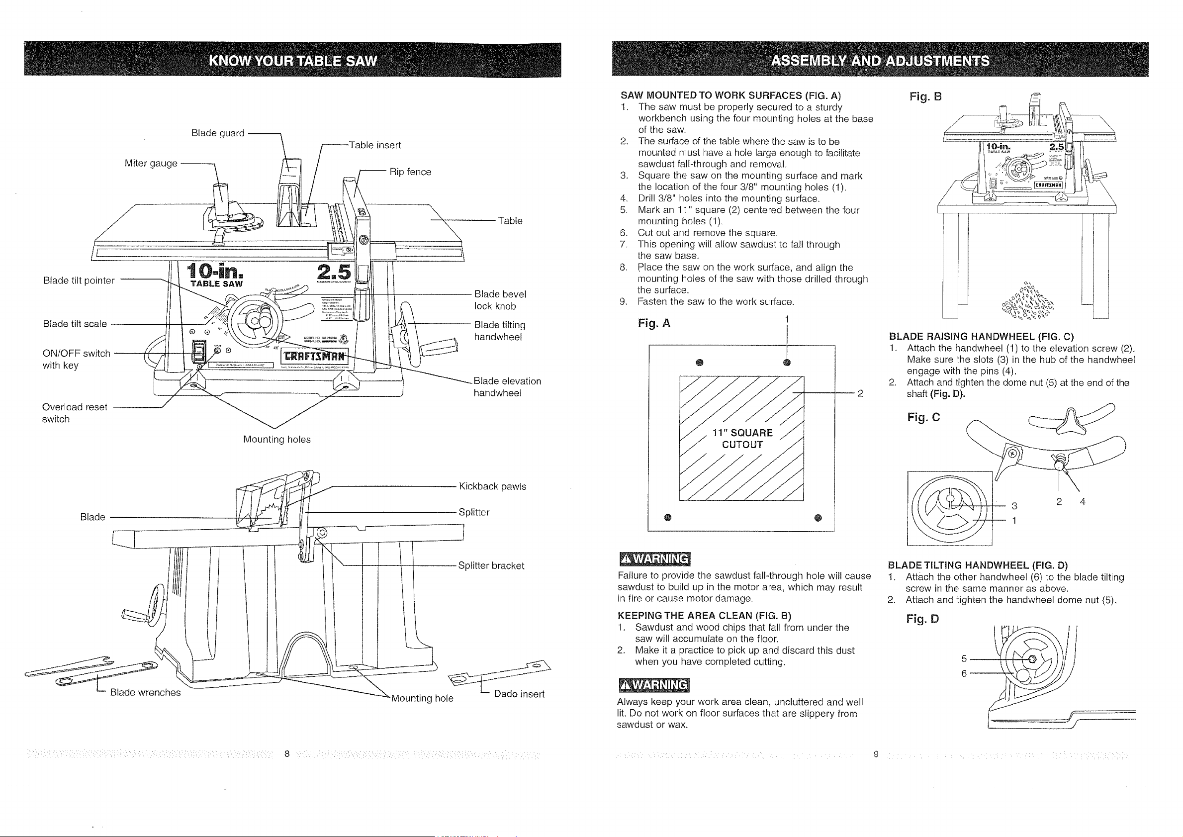
Miter gauge
Blade guard
31einsert
Rip fence
tO-i.o 2,5
Blade tilt pointer TABLE SAW ....................
Blade tilt scale
Overload reset
switch
Mounting holes
Table
Blade bevel
lock knob
Blade tilting
handwheel
•Blade elevation
handwheet
Blade
_nches
Kickback pawls
Splitter
Splitter bracket
_Mounting hole
: :::i: ::::::: : 8
SAW MOUNTED TO WORK SURFACES (FIG. A)
t. The saw must be properly secured to a sturdy
workbench using the four mounting holes at [he base
of the saw.
2. The surface of the table where the saw is to be
mounted must have a hole large enough to facilitate
sawdust fall-through and removal.
3. Square the saw on the mounting surface and mark
the location of the four 3/8" mounting holes (I).
4. Drill 3/8" holes into the mounting surface.
5. Mark an 11" square (2) centered between the four
mounting holes (1).
6. Cut out and remove the square•
7. This opening will allow sawdust to fall through
the saw base.
8. place the saw on the work surface, and align the
mounting holes of the saw with those drilled through
the surface.
9. Fasten the saw to the work surface.
Fig. A
@
1
1
@
Failure to provide the sawdust fall-through hole will cause
sawdust to build up in the motor area, which may result
in fire or cause motor damage.
KEEPING THE AREA CLEAN (FIG. B)
1. Sawdust and wood chips that fall from under the
saw will accumulate on the f!oor,
2. Make it a practice to pick up and discard this dust
when you have completed cutting,
Always keep your work area clean, uncluttered and well
lit, Do not work on floor surfaces that are slippery from
sawdust or wax.
Fig. B r_i:__ '
( i
BLADE RAISING HANDWHEEL (FIG. C)
1, Attach the handwheel (1) to the elevation screw (2),
Make sure the slots (3) in the hub of the handwheel
engage with the pins (4),
2. Attach and tighten the dome nut (5) at the end of the
shaft (Fig. D).
Fig. C
3 2 4
BLADE TILTING HANDWHEEL (FIG. D)
t. Attach the other handwheel (6) to the blade tilting
screw in the same manner as above.
2, Attach and tighten the handwheel dome nut (5),
Fig. O
• •• i i•• i ¸
4
Loading ...
Loading ...
Loading ...