Loading ...
Loading ...
Loading ...
6
REV 2 - 1401030955
L-C2-356
e. Close the dedicated gas-supply shut-off
valve, then slide the grill into place. Do not
to pinch, kink, or damage the gas connector
line.
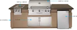
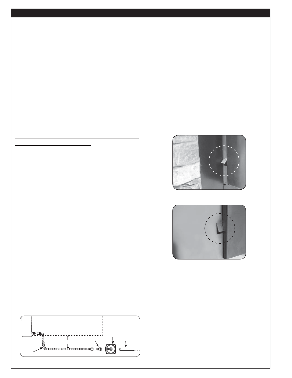
Note: Each side of the unit has a tab just
behind the control panel. These tabs
prevent the control panel from moving
inward. If the tabs interfere with the
unit sliding in (see Fig. 6-1), use pliers
to bend them inward so that they clear
the enclosure sides. Leave the tabs
slightly out to ensure they still keep
the control panel from moving inward
(see Fig. 6-2).
Note: Additional tabs are provided on the
side and rear panels and are only
needed when installing in combustible
framing. See pg. 4 for details.
3. POSITIONING THE BURNER CAP
Place the burner cap so it is centered over the
burner. Ensure that it rests securely in place.
INSTALLATION (Cont.)
f. If an orifi ce change is necessary, replace
the orifi ce with the correct sized one.
g. Replace the sideburner tube over the orifi ce,
aligning the burner over the electrode,
taking care not to detach it from the wire.
h. Replace the burner retaining clip (underneath
burner), and burner cap.
i. Repeat steps c. through h. for the second
burner, then replace the grid and cover.
j. Replace the control panel, being sure
to reconnect the spark generator wires.
Replace the control knobs.
2. CONNECTING THE GAS SUPPLY
THE SUPPLIED REGULATOR MUST BE
REMOTELY ATTACHED IN-LINE BETWEEN THE
GAS SUPPLY AND THE UNIT.
Always ensure the orifi ces and regulator are set
for the gas type your unit is to be installed to.
a. Connect a C.S.A. listed
1
/
2
" fl ex connector
(not included) to the adapter found on the
manifold.
b. Install a
1
/
2
" fl are -
1
/
2
" NPT adapter to the
fl ex connector. Then connect the supplied
regulator to the adapter using pipe joint
compound resistant to all gasses. Orient
so that the arrow stamped on the regulator
points in the direction of the gas fl ow.
c. Run the gas supply pipe and install to the
regulator. Use pipe joint compound resistant
to all gasses. Ensure connections are tight.
(An adapter is required if the gas supply pipe
is other than
1
/
2
" in diameter.)
d. Turn all burner control knobs to the OFF
position. Turn the gas supply on. Then
carefully check all gas connections for
leaks with a brush and half-soap/half-water
solution before lighting. Never use a match
or open fl ame to test for leaks.
Fig. 6-1 Tab may interfere when
sliding in unit
Fig. 6-2
Tab slightly bent in for
clearance
Fig. 6-4
Flex connector
(Side burner)
Adapter
Regulator
Gas supply
6" Grill clearance
Loading ...
Loading ...
Loading ...