Operating Instructions
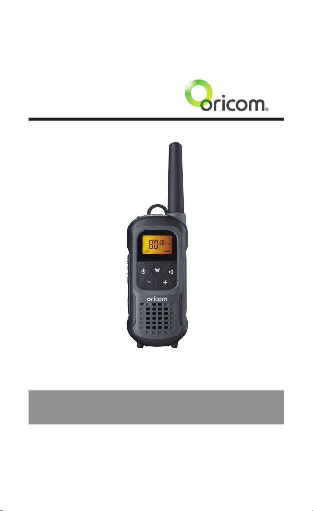
UHF2500 80 Channel UHF
Citizen Band Radio
Keep this user guide for future reference.
Always retain your proof of purchase in case of warranty service.

Need Help?
If you need assistance setting up or using your Oricom product now or
in the future, call Oricom Support.
Australia 1300 889 785 or (02) 4574 8888
www.oricom.com.au
Mon-Fri 8am – 6pm AEST
New Zealand 0800 674 266
www.oricom.co.nz
Mon-Fri 10am – 8pm NZST

3
Table of Contents
Safety Information and Warnings ................................... 4
Getting Started .............................................................. 9
Controls and Indicators ................................................ 13
Operation ..................................................................... 14
UHF Channels and Frequencies .................................... 23
Express Warranty ......................................................... 26
Early in 2011 new AS/NZS Standards came into effect allowing operators to use additional narrowband channels
and also use narrowband transmissions on some current wideband channels.
Why did the ACMA increased the number of available UHF CB channels?
To provide additional channel capacity within the UHF CB Band the ACMA has changed the majority of the current
wideband 80 channel use to narrowband 80 channel use.
Wideband channel use will be gradually phased out as users upgrade their existing radio’s. This increased the
number of channels up to 80, 75 of which are useable voice channels.
This means that the new Oricom narrowband radio you have purchased will have more channels than older
wideband radios. Some of these channels are locked and cannot be used, (see the attached channel chart for more
information).
What issues may users experience during the transition phase?
When a new narrowband radio receives a transmission from an older wideband radio the speech may sound loud
and distorted - simply adjust your radio volume for the best listening performance. When an older wideband radio
receives a signal from a new narrowband radio the speech may sound quieter - simply adjust your radio volume for
best listening performance. When operating a narrowband radio or Channel 41 - 80 interference is possible from
wideband radios transmitting on high power or on adjacent frequency.
The issues described above are not a fault of the radio but a consequence of mixed use of wideband and
narrowband radios.
It is expected that as older wideband radios are removed from service that this issue will be resolved. Most radios
in use will be narrowband eliminating this issue.
This information is current at time of printing. For further up to date information please visit www.acma.
gov.au
Oricom Connecting you now.
This unit complies with all relevant Australian and New Zealand approval
requirements AS/NZS 4365: 2011 including radio communications
(Electromagnetic Radiation Human Exposure) standard 2003.
R-NZ

Safety Information and Warnings
4
Safety Information and Warnings
WARNING
Information on Safe Operation
Read This Information Before Using Your Oricom Radio.
The operation of your UHF radio in Australia and New
Zealand is subject to conditions in the following licenses:
In Australia the ACMA Radio communications (Citizen Band
Radio Stations) and in New Zealand by MED the General
User Radio License for Citizen Band Radio.
Radio Antenna
Do not use any radio that has a damaged antenna. If a
damaged antenna comes in contact with the skin, a minor
burn may result.
Unauthorized antennas, modifications, or attachments
could damage the radio and violate compliance. Do NOT
change or modify the antenna.
Do NOT hold the antenna when the radio is “IN USE.”
Holding the antenna reduces range and may cause bodily
harm.
Safety and general use whilst in a vehicle
Check the State and Federal laws and regulations
regarding the use of two way radios in the area where you
drive, and always obey them.
For Vehicles tted with Air Bags
Do not place your radio in the area over an air bag or in the
air bag deployment area. Air bags inate with great force. If a
radio is placed in the air bag deployment area and the air bag
inates, the radio may be propelled with great force and cause
serious injury to the occupants of the vehicle.
Read all these Safety Warnings before you install or
charge the rechargeable batteries.
• Donotdisposeoftherechargeablebatteriesinareas
they may explode.
• Useonlytherechargeablebatteriessuppliedwiththe
product. Improper use, or use of unapproved batteries
may present a risk of fire, explosion, or other hazard,
and may invalidate any approval or warranty.

Safety Information and Warnings
5
WARNING
• Exerciseextremecarewhenhandlingbatteriesinorder
not to short the batteries with conducting materials such
as rings, bracelets and keys. The batteries or conduction
material may overheat explode and or cause burns.
• Neverreplaceorchargethebatteriesinapotentially
explosive atmosphere (such as where gas is leaking) as
contact sparking may occur while installing or removing
thebatteriescauseareoranexplosion.
• Donotmodify,cut,disassemble,crush,bend,puncture,
heat or damage the batteries.
• Ifthebatteriesleak,donotletthebatteryliquidtouch
skin or eyes. If this happens, immediately flush the
affected areas with water, and seek medical assistance.
Released electrolyte is corrosive and may cause damage
to the eyes and skin. It may be toxic if swallowed.
• Donotimmerseorexposethebatteriestowaterorother
liquids.
•Ifyoubelievethebatteriesaredamaged,remove
product from the charger and stop using the product.
Contact Oricom for assistance.
• Neverusedamagedbatteriesastheymayexplode.
• Removebatterieswhentheyarenolongerabletohold
a charge and when the equipment will not be used for
an extended period of time. Dispose of the batteries
according to local regulations, never in your household
rubbish.
• Riskofexplosionifbatteryisreplacedbyanincorrect
type. Only use the AC power adaptor supplied with
this product. Using any other AC adaptor will invalidate
any approvals and warranty and could be potentially
dangerous.
•Donotattempttochargenon-rechargeableAlkaline
batteries.

Safety Information and Warnings
6
WARNING
Potentially Explosive Atmospheres
Turn your radio OFF when in any area with a potentially
explosive atmosphere. Sparks in such areas could cause
anexplosionorreresultingininjuryorevendeath.
NOTE: Areas with potentially explosive atmospheres are
often, but not always clearly marked. They include fueling
areas such as below deck on boats; fuel or chemical
transfer or storage facilities; areas where the air contains
chemicals or particles, such as grain, dust, or metal
powders; and any other area where you would normally be
advised to turn off your vehicle engine.
Blasting Caps and Areas
To avoid possible interference with blasting operations, turn
your radio OFF near electrical blasting caps or in a “blasting
area” or in areas posted: “Turn off the two way radio.”
Obey all signs and instructions.
Exposure to Radio Frequency Energy
Your Oricom two-way radio complies with Australian
Communications Authority Radio communications
(Electromagnetic Radiation-Human Exposure) Standard, 2003.
To assure optimal radio performance and make sure
human exposure to radio frequency electromagnetic energy
is within the guidelines set out in the above standards
always adhere to the following procedures.
Transmit and Receive Procedure
Your two-way radio contains a transmitter and a receiver.
To control your exposure and ensure compliance with the
general population/uncontrolled environment exposure
limits, always adhere to the following procedure:
• Transmitnomorethan50%ofthetime.
• Toreceivecalls,releasethePTTbutton.
• Totransmit(talk),pressthePushtoTalk(PTT)button.
Transmitting50%ofthetime,orless,isimportantbecause
the radio generates measurable RF energy exposure
only when transmitting (in terms of measuring standards
compliance).
Always hold the radio approximately 5cm in front of your
mouth with the antenna pointing away from your head.

Safety Information and Warnings
7
WARNING
Radio Operation and EME Exposure
Unauthorized antennas, modifications, or attachments
could damage the radio and violate compliance.
Do NOT hold the antenna when the radio is “IN USE.”
Holding the antenna reduces the effective range.
Do not use the radio if the antenna is damaged. If a
damaged antenna makes contact with your skin, a minor
burn can result.
If you wear a radio on your body when transmitting, always
ttheradioonthebeltclip(supplied).Alwaysensurethe
radio and it's antenna are at least 5cm from your body
when transmitting.
Electromagnetic Interference/Compatibility
Nearly every electronic device is susceptible to elec-
tromagnetic interference (EMI). To avoid the possibility of
electromagnetic interference and/or compatibility conicts,
turn off your radio in any location where posted notices
instruct you to do so such as health care facilities.
Aircraft
When instructed to do so, turn off your radio when onboard
an aircraft. Any use of a radio must be in accordance with
applicable regulations per airline crew instructions.
Medical Devices - Pacemakers
The Advanced Medical Technology Association
recommends that a minimum separation of 6 inches (15cm)
be maintained between a handheld wireless radio and a
pacemaker. These recommendations are consistent with
the independent research by and recommendations of the
U.S. Food and Drug Administration.
Peoplewithpacemakersshould:
• ALWAYSkeeptheradiomorethan15cmfromtheir
pacemaker when the radio is turned ON.
• Notcarrytheradiointhebreastpocket.
• Usetheearoppositethepacemakertominimizethe
potential for interference.
• TurntheradioOFFimmediatelyifthereisanyreasonto
suspect that interference is taking place.

Safety Information and Warnings
8
WARNING
Medical Devices - Hearing Aids
Some radios may interfere with some hearing aids.
In the event of such interference, you may want to consult
your hearing aid manufacturer to discuss alternatives.
Other Medical Devices
If you use any other personal medical device, consult the
manufacturer of your device to determine if it is adequately
shielded from RF energy. Your physician may be able to
assist you in obtaining this information.
General warnings
Keep the radio out of reach of babies and young children.
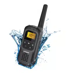
Waterproof: IPX7
Oricom’sUHF2500radioisdesignedtomeetthewaterproong
standardIPX7.
The UHF2500 is designed to oat when in water, the LED light will
ash and LCD backlight to assist you in locating the radio when in
water.
The IPX7 means:
Beingdenedashavingnoingressofwaterwhenimmersedat
1meterfor30minutes.(TomeettheIPX7waterproofrating,the
accessorysocketcovermustbeinplace,thebatterymustbetted
correctly)
NOTE: DO NOT submerge the transceiver in water if there is any
reason to suspect the waterproof protection may not be effective.
For example, in cases where the battery cover or external jack cap
rubber seal is damaged, the transceiver/battery cover/jack cap is
cracked or broken, or the transceiver has been dropped, or when
the battery cover or Jack cap are detached form the transceiver.
9
Getting Started
Pack Contents
Model No. UHF2500-1
1 UHF2500 Handheld Radio
3 1200mAH AA Ni-MH
Rechargeable Batteries
1 AC Adaptor
1 USB Cable
1 Oricom Carabiner
1 Belt Clip
Model No. UHF2500-2
2 UHF CB Handheld Radios
6 1200mAH AA Ni-MH
Rechargeable Batteries
1 AC Adaptor
1 USB Y Cable for Charging
1TwinChargingPod
2 Oricom Carabiners
2 Belt Clips
Accessories and spare parts can be purchased directly from Oricom.
Visit www.oricom.com.au or call 1300 889 785 or (02) 4574 8888.
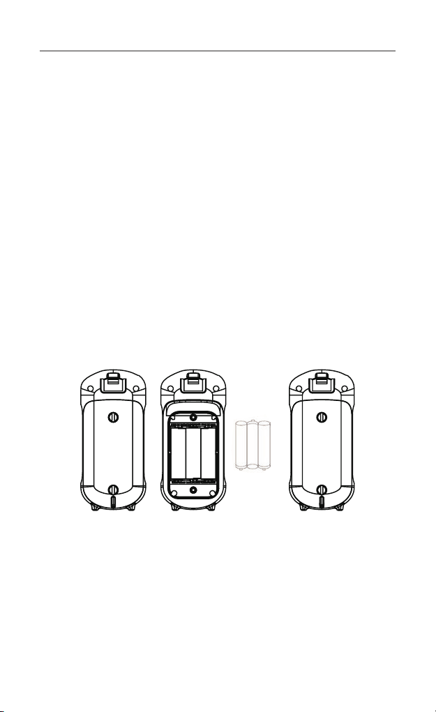
Installation
Installing the Batteries
Figure 3 Figure 4
Caution: Observe the proper battery polarity orientation when installing batteries.
Incorrect positioning can damage both the batteries and the unit.
a. Unlock two screws.
b. Install the rechargeable batteries (supplied) by following the orientation as
shown in Figure 3.
c. Replace the Battery Compartment Cover. Tighten the screws see Figure 4.
NOTE: You can use Alkaline batteries if required, however YOU MUST NOT
PLACE THE RADIOS ON THE CHARGER WITH ALKALINE BATTERIES
INSERTED as this will damage the radio.
10
Getting Started
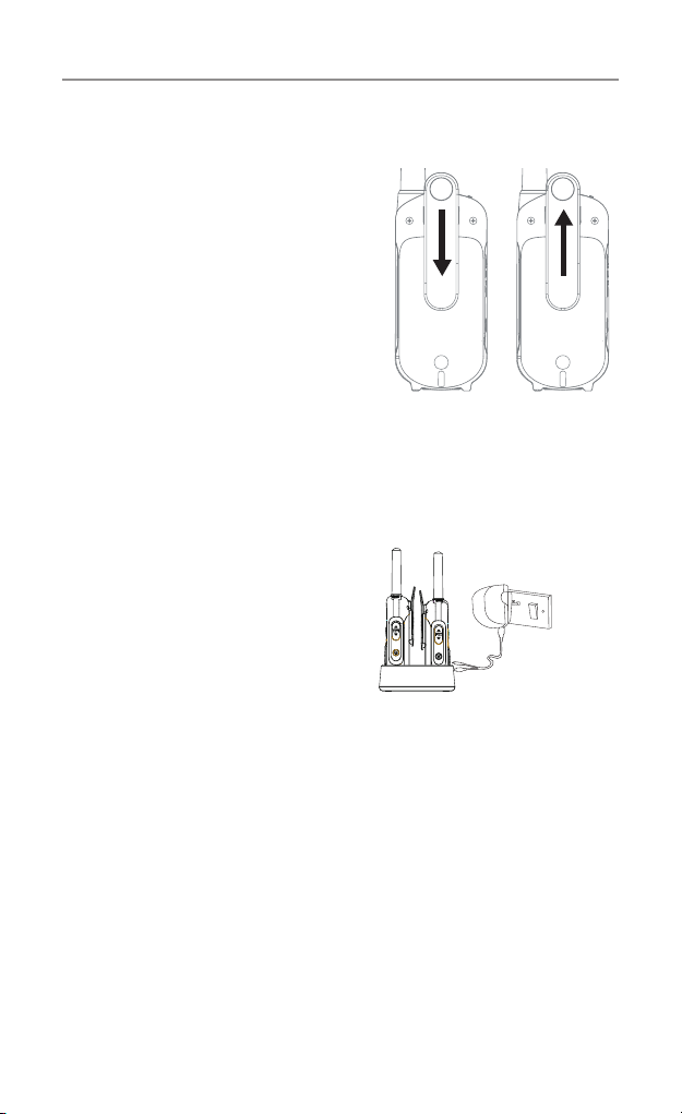
UHF2500 Battery Charging
a. Connect the supplied USB “Y”
cable to the AC power adaptor
then connect one of the mini
USB connectors to the charge
pod, place the radios in the
charge pod as indicated.
DO NOT use the second mini
USB connector for any other
application.
b.IfthechargePodisnot
available then the 2 mini USB
connectorscanbettedtothe
mini USB connectors found under the protective cover on the top
of the UHF2500 radios.
c.PlugACadaptorintoanACwallsocketandturnon,theLEDs
on the charge pod will turn on and the battery Icon on the radio
display will start ashing to indicate that the radios are charging.
The batteries can take more than 12 hours to fully charge.
Installing the Belt Clip
Slide the Belt clip into the slot as
shown in Figure 1.
A “click” indicates the Belt clip is
locked into position.
Removing the Belt Clip
PulltheBeltCliplatchforward
(away from the unit)
While pulling the Belt Clip latch,
push up the Belt Clip as shown in
Figure 2.
Figure 1
Figure 2
Belt Clip latch
Important: Always turn off
the units when charging.
This will shorten the
charging time.
Main socket
DO NOT USE THE SECOND MICRO USB
CABLEFORANYOTHERPURPOSE
WHEN THE OTHER ONE IS USED IN
THECHARGERPOD.
11
Getting Started
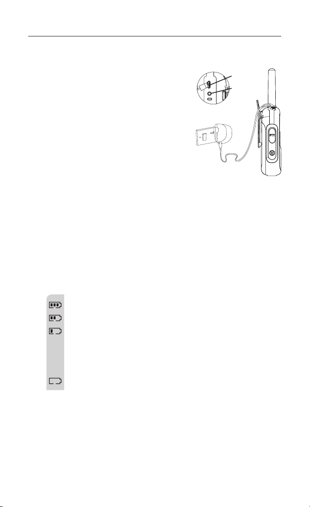
Charging the batteries
(using adaptor)
a. Lift the charge socket cover located on
the top of the handset.
b. Insert the USB connector into the
socket on the top of the radio.
c.Plugthemainsadaptorintoa230V
AC, 50Hz main socket with the switch
on the socket set to Off.
d. Use only the power adaptor listed in
the user instruction.
Then switch ON the main socket.
Battery meter
The battery meter is located in the left corner of the LCD screen.
It appears like a battery with three bars inside. These indicate the
amount of power available. When the battery level reaches its
minimum level, the unit will emit two beep tones and automatically
it will power off.
Your UHF2500 can detect the battery charge in 4 levels;
Battery charge at high level.
Battery charge at medium level.
Battery charge at low level. At this level, the radio will emit
a “beep” sound for every 10 seconds in standby mode.
TIP: At this stage, you need to recharge the unit at
once, otherwise the battery will run down totally.
Battery charge at very low level. When the battery level
reaches its minimum level, the unit will emit two beep tones
and automatically turn off the power.
Important: You need to charge the unit for approximately
14 hours.
CAUTION: Risk of explosion if battery is replaced by
an incorrect type. Dispose of used batteries
according to local regulations.
Mic/spk jack
Charge jack
12
Getting Started
Battery life
Your radio has a built in power saver to make the batteries last
longer. But when you are not using the units, turn them OFF to
conserve battery power.
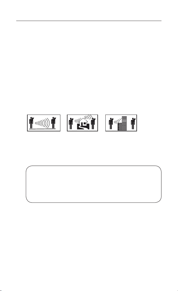
Transmitting range
The talk range depends on the environment and terrain. In
general the radio can reach further in wide open spaces, without
obstructions such as hills or buildings. It will be affected by
concrete structures, heavy foliage and by operating radios indoors
or in vehicles. Don’t try to use two radio units which are less than
1.5m (5 feet) apart. Otherwise, you may experience interference.
Optimal Range
Outdoors
Flat, open areas
Medium Range
Outdoors
Buildings or trees
Also near residential
buildings
Minimal Range
Outdoors
Dense foliage or
mountains. Also inside
some buildings
IMPORTANT SAFETY WARNING
To reduce radio frequency exposure when you are using your
hand-held, hold the unit at least 5cm (2 inches) away from
your face.
13
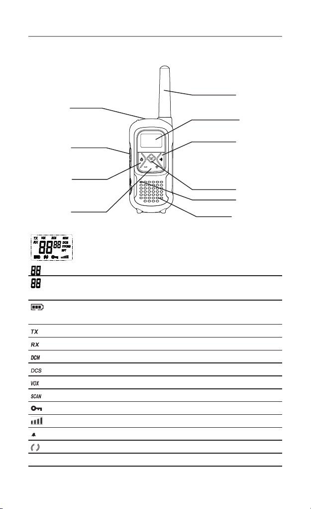
Antenna
Speaker
LCD Screen
- Displays the current channel
selection and other radio
symbols.
PTT ( PUSH TO TALK)
button
- Press and hold to
transmit.
+
/ - Buttons
- Press to change
channels, volume, and
to select settings during
programming.
MIC (Microphone)
MENU Button
CALL button
- Press to send
Ringing tone to other radios.
Power On / Off
- Press and hold to turn
the unit ON or OFF.
Ear/Mic/Charg
e
j
ack
Controls and Indicators
Controls and Indicators
LCD Screen
Channel number. Changes from 1 to 80 as selected by the user.
CTCSS code. Changes from 1 to 38 as selected by the user. DCS
code changes from 1-83.
Displays the Battery charge level. When the bars are reduced, the
battery needs recharging.
Displayed when transmitting a signal.
Displayed when receiving a signal.
Displayed when the Dual Watch function turned on.
Displayed when the Digital Code System turned on.
DisplayedwhentheVOXfeatureisenabled.
Displayed when scanning all channels.
Displayed when the Key Lock feature is activated.
Displays the current Speaker volume level.
Displayed when the call signal is on.
Displayed when the vibrator function is activated.
RPT
Displayed when the Repeater Function is selected.
14
Operation
Operation
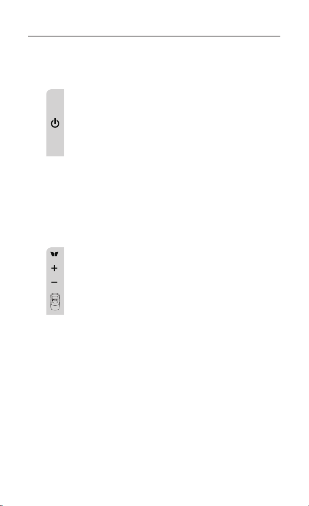
Turning the Unit ON/OFF
To Turn ON;
a.Press&holdON/OFFbuttonfor2secondsuntiltheLCD
screen turns ON and displays the current channel.
To switch OFF;
b.Press&holdON/OFFbuttonfor2secondsuntiltheLCD
screen turns blank.
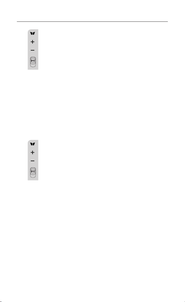
Changing volume
Pushthe+ or - buttons to change the volume.
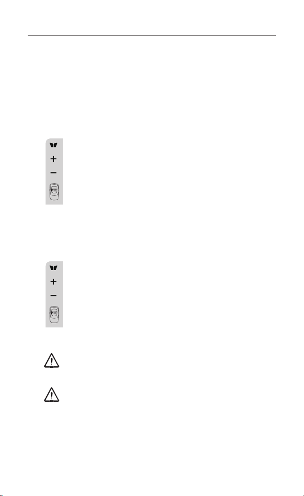
Changing Channels
The radio has 77 available channels, to communicate with other
radios, it must be tuned to the same channel.
a.PresstheMENU button once, the current channel
number ashes on the LCD Screen.
b.Pressthe+ or – button to select the desired channel. The
channel changes from 1 to 80, or vice versa.
c.PressthePTTbuttontoconrmthechannelsetting.
Channels 1 to 8 and 41 to 48 are used for repeaters and are paired
with higher channels as output/input (1/31, 2/32, etc.)
Check for local repeater activity before using these channels in
Simplex mode to avoid interference. Channels 9 and above are the
best choices for general use in Simplex mode.
Youcanndmoreinformationaboutchannelsandfrequenciesby
visiting the Web site http://www.acma.gov.au
Note: Refer to the “Channel Table” section of this Owner’s Manual
for detailed frequency listing.
PushMenu button 2 times to select RPT. Use + or - buttons to
turn on/off.
This can only be turned on, on channels 1 to 8 and 41 to 48. On all
others, it will always be off.
15
Operation
Setting the CTCSS sub-channel
Each channel has 38 sub-channels to let you set up group of users
within the same channel. If you have set the sub-channel, you
can only communicate with other radio users tuned to the same
channel and sub-channel.
To turn the sub-channel function off, simply set the sub-
channel to 0 (zero).
a.PresstheMENU button 3 times, the current CTCSS sub-
channel number ashes on the LCD screen.
b.Pressthe+ or – button to select one of the 38 CTCSS
sub-channels.
c.PressthePTTbuttontoconrmtheCTCSS sub-channel
setting.
SETTING THE DCS ADVANCED DIGITAL CODE.
Each channel also has 83 digital codes to let you set a group of
users for more secured private communication.
a.PresstheMENU button 4 times. DCS code is blinking on
the LCD screen.
b.Pressthe+ or – button to select the desired DCS code.
c.PressthePTTbuttontoconrmtheDCS channel setting.
Transmitting and Receiving
The UHF2500transmissionisSIMPLEX“oneway-at-
a-time.” While you are speaking, you can not receive a
transmission.
The UHF2500 is a class license device. Always identify
yourself when transmitting.
IMPORTANT:BeforetransmittingonaUHFchannellistentoensure
it is not already in use.
16
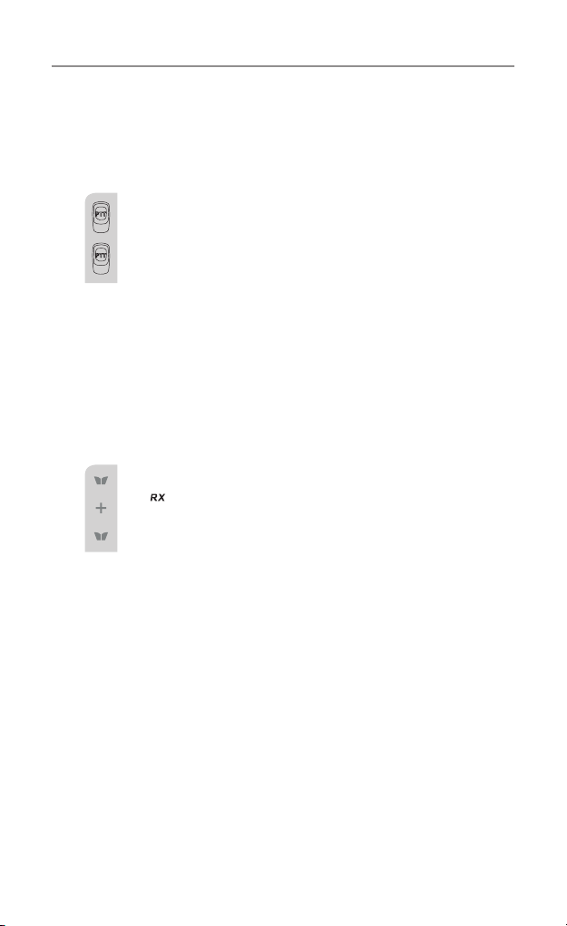
Transmitting (sending speech)
The unit is continuously in Receive mode when the unit is turned
ON and not transmitting. When a signal is received on the current
channel, “RX” icon will be displayed on the LCD screen.
a.PressandholdthePTT (push to talk) button to transmit
your voice. “TX” icon will be displayed on the LCD Screen.
b. Hold the unit in a vertical position with the MIC
(Microphone) 5 cm away from the mouth. While holding
the PTT button, speak into the MIC (microphone) in a
normal tone of voice.
c. Release the PTT button when you have finished
transmitting.
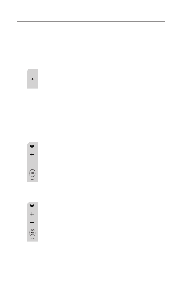
Monitor
You can use the Monitor feature to check for weak signals on the
selected channel.
a.Pressthe+&MENU button at the same time,
“ ” icon will be displayed on the LCD screen. Your radio
will pick up all signals on the selected channel, including
background noise.
b.PressMENU button to stop the channel monitoring.
Setting the PTT (Voice Activated) Sensitivity
InVOXmode,theradiowilltransmitasignalonlywhenitis
activated by your voice or other sounds around you. The unit will
transmit for a further 2 seconds after you cease talking.
ThelevelofVOXsensitivityisshownbyanumberontheLCD
Screen. At the highest level, the units will pick up softer noise
(including background noise); at the lowest level, it will pick up
louder noise.
Operation
17
a.PresstheMENU button 5 times, “VOX” icon will be
displayed and “OFF” ashes on the LCD screen.
b.Pressthe+buttontosettheVOXsensitivityinto
maximum level (the maximum level is “3 ”.) To deactivate
theVOXfunction,pressthe– button until “OF” appears
on the LCD Screen.
c.PressthePTTbuttontoconrmyoursetting.“VOX” will
steadilyappearontheLCDScreenaslongastheVOX
feature is activated.
VOXoperationisnotrecommendediftheradiowillbeusedina
noisy or windy environment.
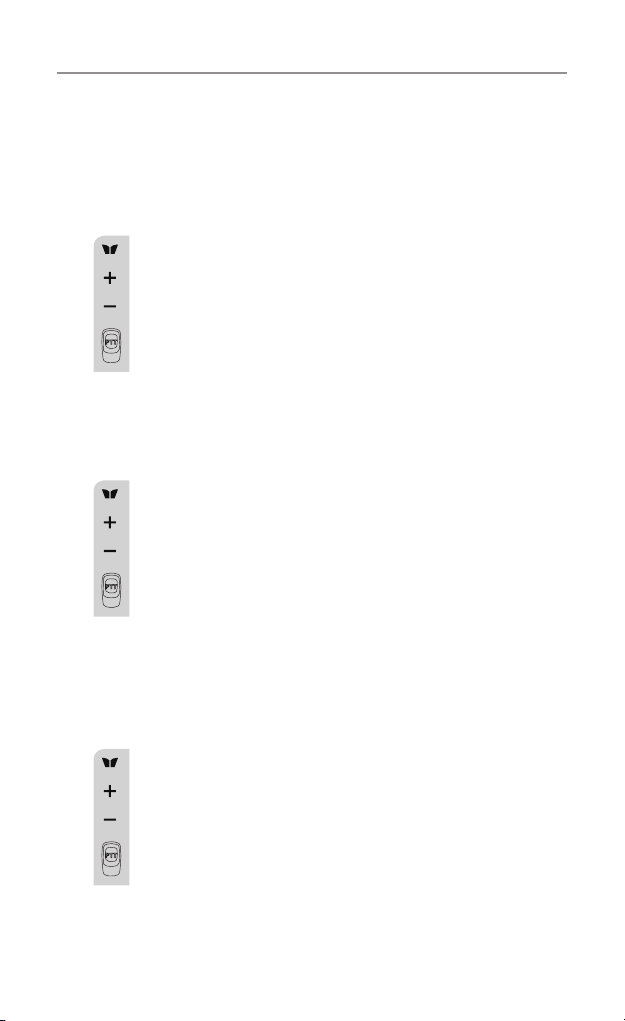
Activating the Auto Channel Scan
Channel scan searches for active signals in an endless loop for all
80 channels, 38 CTCSS codes and all 83 DCS codes.
Scanchannels:PresstheMENU button 6 times, “SCAN”
icon will display on LCD screen.
Pressthe+ or – button to begin scanning channels
when an active signal is detected, channel scan pauses
on the active channel.
ScanCTCSSchannels:PresstheMENU button 7 times,
CTCSS flashes on the LCD screen press the + or –
button to begin scanning the CTCSS from 1-38.
ScanDCSchannels:PresstheMENU button 8 times, DCS
ashesontheLCDscreen.Pressthe+ or – button to
begin scanning DCS code 1-83.
PressthePTTbuttontoconrmyoursetting.
Operation
18
Vibrator and Call alert
Your radio can alert you to incoming signal by emitting an audible
call tone and vibration signal.
Call-Ring tone
You can send a Call-ring tone to other radio users to give
an alert that you want to communicate with them.
Press the CALL button
You will hear a ring tone for about two seconds; “TX” icon
appears on the LCD screen. Any other units within the
transmitting range and tuned to the same channel and sub-
channel (if applicable) will hear the Call-ring tone.
Selecting a Call- Ring tone
Your UHF2500 is equipped with 15 different types of Call-Ring tones.
a.PresstheMENU button 9 times, the “C01” icon will
display and ash on the LCD Screen.
b.Pressthe+ or – button to select the desired Call-ring
tone. A respective Call-Ring tone sound will be played
when changing from one tone to another.
c.PressthePTTbuttontoconrmyoursetting.
Activating the Vibrator mode
a.PresstheMENU button 10 times; “1” ashes on the LCD
Screen.
b.Pressthe+ or – button to activate the vibrator function.
c.PressthePTTbuttontoconrmyoursetting.
Note: Vibrator and Call tone can be activated at the same time.
Call ring tone calling is only allowed to operate for a maximum of
3 seconds and it is only possible to operate once in any 60 seconds
period.
Operation
19
Setting the Roger Beep
The Roger beep is a tone which is automatically transmitted
whenever the PTT button is released. This alerts the receiving party
to inform you that you have intentionally ended the transmission,
and you are now in receive mode.
a.PresstheMENU button 11 times, the “ON” icon will
ash on the LCD Screen.
b.Pressthe+ or – button to select the Roger beep On/Off.
c.PressthePTTbuttontoconrmyoursetting.
Setting the Key Tone ON or OFF
Thisfeatureallowsyourradiounittoemitaconrmationtoneafter
pressing each button.
a.PresstheMENU button 12 times, the “ON” icon is
ashing on the LCD Screen.
b.Pressthe+ or – button to select Key tone On/Off.
c.PressthePTT buttontoconrmyoursetting.
Setting the Dual Watch Mode
Your radio is capable of monitoring two channels, the current and
another (dual watch) channel. If the unit detects a signal on either
channel, it will stop and receive the signal.
Dualwatchchannel:PresstheMENU button 13 times,
“DCM” icon will be displayed while “OFF ” ashes on the
LCD Screen.
Pressthe+ or – button to select the Dual Watch channel
(1-80, except the current channel).
Dual watch CTCSS channel: Continue pressing the MENU
button to change the CTCSS code.
Pressthe+ or – button to select the desired CTCSS
code (1-38).
Operation

20
Dual watch DCS channel: Continue pressing the MENU button to
change the DCS code.
Pressthe+ or – button to select the desired DCS code (1-83).
PressthePTTbuttontoconrmyoursetting.
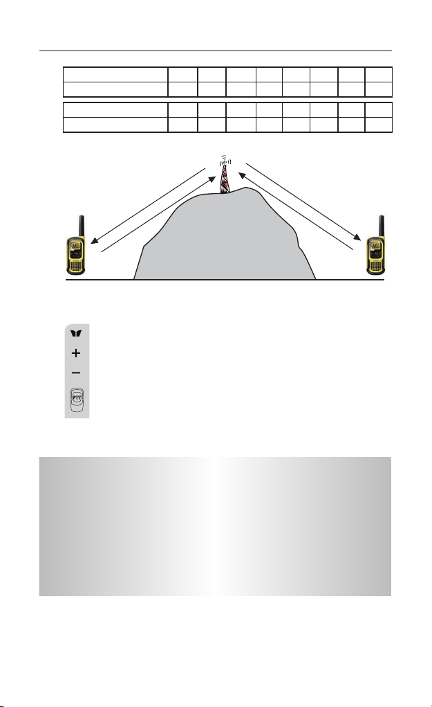
Duplex operation via Repeaters
This feature allows to use local repeater stations that are designed
to automatically re-transmit your broadcast over a large area thus
giving you increased range.
Repeaters stations are privately operated radio systems installed
throughout Australia.
For example, if you wish to access a repeater station in your area
which operates on channel 2 you only need to set the Duplex
access on this Channel.
So, if you are in the range of a local repeater which transmits on
channel 2, after setting your radio to allow access of the repeater
on that channel, you will select channel 2 as normal, but during
transmit operation your radio will automatically transmit to the
repeater on channel 32.
Turning on/off Duplex on channels
a. Select the required channel to suit the repeater station you wish
to access (Channels 1 – 8 and 41 – 48).
b.PresstheMenubuttontwice,“RPT” icon will display.
c.Pressthe+ or – button to set the Duplex function to On or Off.
d.PressthePTTbuttontoconrmyoursetting.
e.TheRPTiconwilldisplaytoindicatethatDuplexissetonthat
channel.
Operation
21
Important
• Speechtransmissionsarenotallowedonchannel22and23
(Receive only).
• CTCSSandCallringtonecallingisdisabledonchannel5and35.
• Callringtonecallingisonlyallowedtooperateforamaximum
of 3 seconds and it is only possible to operate once in any 60
second period.
Receive Channel 1 2 3 4 5* 6 7 8
Transmit channel 31 32 33 34 35* 36 37 38
Receive Channel 41 42 43 44 45 46 47 48
Transmit channel 71 72 73 74 75 76 77 78
* Channel 5 is emergency channel only
Channel 2
Channel 32
Channel 2
Channel 32
Repeater Station
Setting the Repeater function
a. Select your repeater channel to suit the repeater station
you wish to access (Channels 1 – 8 and 41 – 48).
b.PresstheMenubutton2times,“RPT” icon will be
displayed and ashing on the LCD screen.
c.Pressthe+ or – button to set the Repeat function to On
or Off.
d.PressthePTTbuttontoconrmyoursetting.
Operation

22
Operation
Auxiliary Features
Key Lock
The Key Lock feature allows the user to disable the +, –
and MENU buttons so that the UHF2500 settings could not
be changed accidentally.
a. To activate the key Lock feature, press and hold the
MENU button until key lock “ ” icon appears on
the LCD Screen.
b. To deactivate the key Lock feature, press and hold the
MENU button until key lock “ ” icon disappears on
the LCD Screen.
Note: The PTT and CALL buttons will remain functional even if the
Key Lock feature is activated.
LCD Screen Back Light
EverytimethePower/Volbuttonisactivated(exceptPTT
and CALL button), the LCD Screen back light will illuminate
for 5 seconds.
Microphone/Earphone/Charge Jack
Your radio is equipped with an auxiliary microphone,
earphone, and charge jack located at the opposite top side
of the radio.
Torch and SOS function
PressandreleasetheLightbuttonontheleftsideofthe
unit. The LED will light at the bottom of the unit. While LED
is On, press and hold the Light button to activate the SOS
function. To turn Off, press and release the Light button.
Factory Reset
If the radio’s display locks up or stops functioning properly, you
might need to reset your UHF radio.
Caution: This procedure clears all the information you have stored
in your UHF radio.
Before you reset your UHF radio, try turning it off and on again.
If your UHF radio is still not functioning correctly you may need to
reset the UHF radio.
Toreset,PressandHoldCallbuttonandpoweron.
The radio will reset to Channel 12.
23
Channel Frequency Table
Radiocommunications (Citizen Band Radio Stations) Class
Licence 2002
No licence is required to own or operate this radio in Australia
and New Zealand. The Radiocommunications (Citizen Band Radio
Stations) Class Licence 2002 contains the technical parameters,
operating requirements, conditions of licence and relevant standards
for Citizen Band (CB) radios. CB radios must comply with the class
licence for their use to be authorised under the class licence.
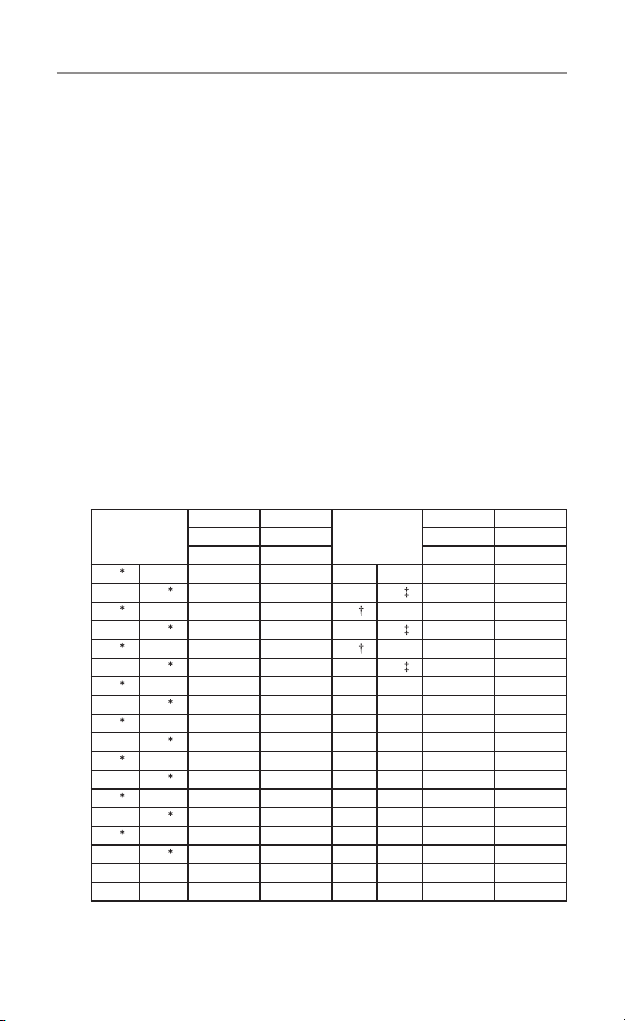
UHF Channels and Frequencies
IMPORTANTNOTE:TheoperationofyourUHFradioinAustraliaand
New Zealand is subject to conditions in the following licenses:
In Australia the ACMA Radio communications (Citizen Band Radio
Stations) and in New Zealand by MED the General User Radio
License for Citizen Band Radio.
Channel
Tx Rx
Channel
Tx Rx
Freq Freq Freq Freq
MHZ MHz MHZ MHZ
01
476.4250 476.4250 21 476.9250 476.9250
41
- 476.4375 61 - -
02
476.4500 476.4500 22 476.9500 476.9500
42
- 476.4625 62 - -
03
476.4750 476.4750 23 476.9750 476.9750
43
- 476.4875 63 - -
04
476.5000 476.5000 24 477.0000 477.0000
44
- 476.5125 64 477.0125 477.0125
05
476.5250 476.5250 25 477.0250 477.0250
45
- 476.5375 65 477.0375 477.0375
06
476.5500 476.5500 26 477.0500 477.0500
46
- 476.5625 66 477.0625 477.0625
07
476.5750 476.5750 27 477.0750 477.0750
47
- 476.5875 67 477.0875 477.0875
08
476.6000 476.6000 28 477.1000 477.1000
48
- 476.6125 68 477.1125 477.1125
9 476.6250 476.6250 29 477.1250 477.1250
49 476.6375 476.6375 69 477.1375 477.1375
UHF Channels and Frequencies
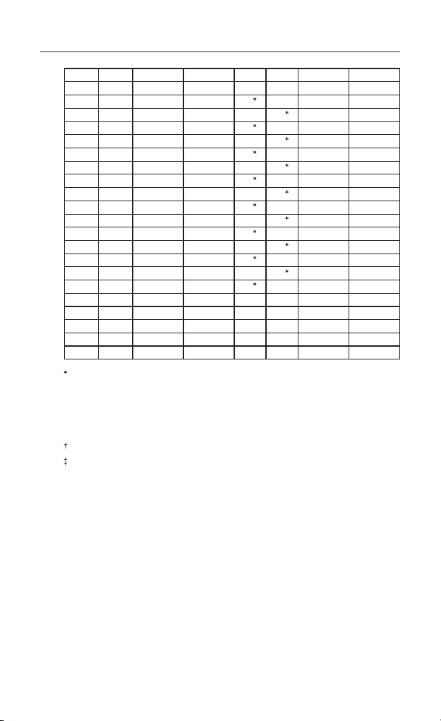
24
10 476.6500 476.6500 30 477.1500 477.1500
50 476.6625 476.6625 70 477.1625 477.1625
11 476.6750 476.6750 31
477.1750 477.1750
51 476.6875 476.6875 71
477.1875 -
12 476.7000 476.7000 32
477.2000 477.2000
52 476.7125 476.7125 72
477.2125 -
13 476.7250 476.7250 33
477.2250 477.2250
53 476.7375 476.7375 73
477.2375 -
14 476.7500 476.7500 34
477.2500 477.2500
54 476.7625 476.7625 74
477.2625 -
15 476.7750 476.7750 35
477.2750 477.2750
55 476.7875 476.7875 75
477.2875 -
16 476.8000 476.8000 36
477.3000 477.3000
56 476.8125 476.8125 76
477.3125 -
17 476.8250 476.8250 37
477.3250 477.3250
57 476.8375 476.8375 77
477.3375 -
18 476.8500 476.8500 38
477.3500 477.3500
58 476.8625 476.8625 78* 477.3625 -
19 476.8750 476.8750 39 477.3750 477.3750
59 476.8875 476.8875 79 477.3875 477.3875
20 476.9000 476.9000 40 477.4000 477.4000
60 476.9125 476.9125 80 477.4125 477.4125
The primary use for these channels is repeater operation using 750 kHz
offset. Channels 1-8 and 41-48 inclusive are used for mobile reception
and channels 31-38 and 71-78 for mobile transmission. In addition, any
designated repeater channel may be used for simplex operation in areas
where it is not used for repeater operation.
Speech telephony shall be inhibited on these channels.
At the time of production Channels 61, 62 and 63 are guard channels and
are not available for use.
Channel 5 and 35 (paired for Duplex repeaters) are reserved as emergency
channels and should be used only in an emergency.
CTCSS and DCS will not operate on channels 5 and 35.
A list of currently authorised channels can be obtained from the ACMA
website in Australia and the MED website in New Zealand. Channel 11
is a calling channel generally used to call others and channel 80 is the
customary road vehicle channel.
Once contact is established on the calling channel, both stations should
movetoanotherunused“SIMPLEX”channeltoallowotherstousethe
calling channel.
UHF Channels and Frequencies

25
Channels 22 and 23 are for Telemetry and Telecommand use, voice
communications are not allowed on these channels by law.
Channel 9 and above are the best choices for general use in Simplex mode.
38 CTCSS CODE LIST
CODE Frequency(Hz) CODE Frequency(Hz)
OFF OFF 20 131.8
1 67.0 21 136.5
2 71.9 22 141.3
3 74.4 23 146.2
4 77.0 24 151.4
5 79.7 25 156.7
6 82.5 26 162.2
7 85.4 27 167.9
8 88.5 28 173.8
9 91.5 29 179.9
10 94.8 30 186.2
11 97.4 31 192.8
12 100.0 32 203.5
13 103.5 33 210.7
14 107.2 34 218.1
15 110.9 35 225.7
16 114.8 36 233.6
17 118.8 37 241.8
18 123.0 38 250.3
19 127.3
UHF Channels and Frequencies

26
Express Warranty (Australia)
ThisExpressWarrantyisprovidedbyOricomInternationalPtyLtdABN
46086116369,Unit1,4SovereignPlace,SouthWindsorNSW2756,
herein after referred to as “Oricom”.
Oricom products come with guarantees that cannot be excluded under
the Australian Consumer Law. You are entitled to a replacement or
refund for a major failure and compensation for any other reasonably
foreseeable loss or damage. You are also entitled to have the goods
repaired or replaced if the goods fail to be of acceptable quality and the
failure does not amount to a major failure.
Oricom warrants that the product is free from defects in materials
orworkmanshipduringtheExpressWarrantyPeriod.ThisExpress
Warranty does not extend to any product from which the serial number
has been removed or was purchased outside of Australia.
NothinginthisExpressWarrantyexcludes,restrictsormodiesany
condition, warranty, guarantee, implied term, right or remedy pursuant
to the Australian Consumer Law and which may not be so excluded,
restrictedormodied.Forsuchconditions,terms,guaranteesand
warrantiesthatcannotbeexcluded,restrictedormodied,Oricomlimits
the remedies available to extent permitted in the relevant legislation.
TheExpressWarrantyPeriodwillbe3yearsfromthedateofpurchase
of the product evidenced by your dated sales receipt. You are required
to provide proof of purchase as a condition of receiving Express
Warranty services.
You are entitled to a replacement product or repair of the product at
our discretion according to the terms and conditions of this document
ifyourproductisfoundtobefaultywithintheExpressWarrantyPeriod.
This Express Warranty extends to the original purchaser only and is not
transferable.
Express Warranty

27
Express Warranty
ProductsdistributedbyOricomaremanufacturedusingnewmaterials
or new and used materials equivalent to new in performance and
reliability. Spare parts may be new or equivalent to new. Spare parts are
warranted to be free from defects in material or workmanship for thirty
(30)daysorfortheremainderoftheExpressWarrantyPeriodofthe
Oricom branded product in which they are installed, whichever is longer.
DuringtheExpressWarrantyPeriod,Oricomwillwherepossiblerepair
and if not replace the faulty product or part thereof. All component
parts removed under this Express Warranty become the property of
Oricom. In the unlikely event that your Oricom product has a recurring
failure, Oricom may always, subject to the Competition and Consumer
Act 2010, at its discretion, elect to provide you with a replacement
product of its choosing that is at least equivalent to your product in
performance.
No change to the conditions of this Express Warranty is valid unless it is
made in writing and signed by an authorised representative of Oricom.
Oricom will not be liable under this Express Warranty, and to the extent
permitted by law will not be liable for any defect, loss, damage or injury
arising out of or in connection with a:
1. Failure by you to adhere to the warnings and follow the instructions
set out in this user guide for the proper installation and use of the
product;
2. Wilful misconduct or deliberate misuse by you of the product;
3. Any external cause beyond our control, including but not limited to
power failure, lightning or over voltage; or
4.Modicationtotheproductorservicescarriedoutontheproductby
anyone other than Oricom or Oricom’s authorised service provider.

28
Express Warranty
How to make a claim under your Express
Warranty in Australia
Oricom has a simple warranty process for you to follow:
•PleasecalloremailourCustomerSupportTeam,1300889785or
support@ oricom.com.au.
•A Customer Support Team member will verify after troubleshooting
withyouifyourproductqualiesunderwarranty.Ifso,theywillgive
youaProductReturnAuthorisationnumber.
•We will then email or fax a Return Authorisation form and a Repair
Notice (if necessary), together with instructions on how to return the
goods for warranty service.
PleasenotethatifaCustomerSupportTeammemberadvisesthat
your product does not qualify for return, this warranty does not apply to
yourproduct.ProductsthatareauthorisedtobereturnedtoOricomin
Australia must include all of the following:
•A completed Return Authorisation form
•AcopyofyourProofofPurchase(pleasekeepyouroriginalcopy)
•The faulty product, including all accessories.
Send the approved returns to:
OricomInternationalPtyLtd
Locked Bag 658
South Windsor NSW 2756 Australia
PleasenotethatthisExpressWarrantyexcludesexpensesincurredby
you in returning any faulty product to us. You must arrange and pay any
expenses incurred (including postage, delivery, freight, transportation or
insurance of the product) to return the faulty product to us, however, we
will arrange delivery of the repaired or replaced faulty product to you.

29
Express Warranty
Important Information
Repair Notice
Pleasebeawarethattherepairofyourgoodsmayresultintheloss
of any usergenerated data (such as stored telephone numbers, text
messagesandcontactinformation).Pleaseensurethatyouhave
made a copy of any data saved on your goods before sending for
repair.Pleasealsobeawarethatgoodspresentedforrepairmaybe
replaced by refurbished goods or parts of the same type rather than
being repaired.

ORICOM CUSTOMER SUPPORT
Oricom have a trained and dedicated team of Customer Support
Representatives, each with the knowledge and resources to
assistinansweringyourquestionsquicklyandefciently.
Oricom Support - Australia
For all product enquiries, troubleshooting or to discuss the
range of Oricom products, feel free to contact Oricom or visit
our website for answers to frequently asked questions.
1300 889 785
Monday - Friday 8am – 6pm AEST
Email: [email protected]
www.oricom.com.au
Oricom Support - New Zealand
0800 674 266
Monday - Friday 11am - 7pm NZST
Email: [email protected]
www.oricom.co.nz
Ref: 29112017