Loading ...
Loading ...
Loading ...
OUTDOOR TECHNICAL OVERVIEW
B-24
ENGLISH
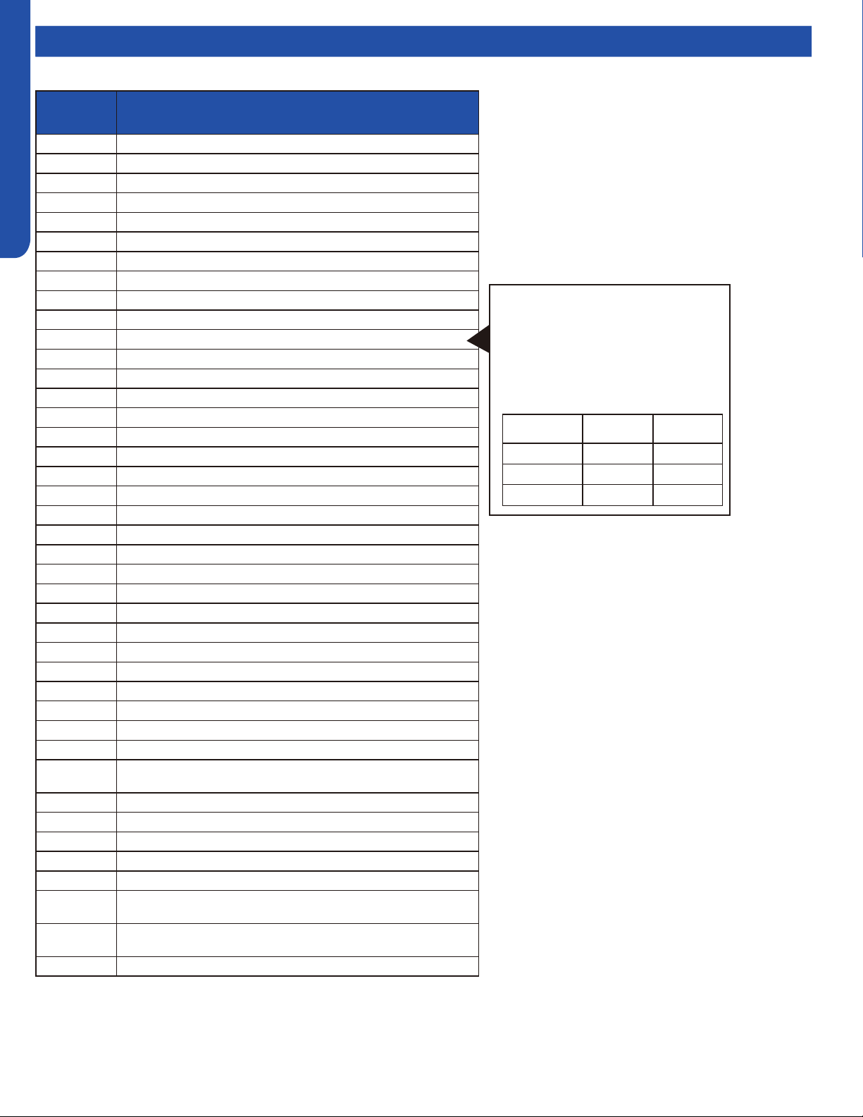
Topic TitleError Codes
LED Error
Code
Diagnosis
1 Outdoor EEPROM failure
2 IPM overcurrent or short circuit
4 Communication failure between the IPM and outdoor PCB
5 Module operated overload (compressor overload protection)
6 Module low or high voltage
8 Overheat protection for discharge temperature
9 Malfunction of the DC fan motor
10 Malfunction of defrost temperature sensor
11 Suction temperature sensor failure
12 Ambient temperature sensor failure
13 Discharge temperature sensor failure
15 Communication failure between the indoor & outdoor unit
16 Lack of refrigerant or discharging
17 4-way valve switching failure
18 Loss of synchronism detection
20 Indoor thermal overload
21 Indoor unit overload protection, heating mode only.
21 Indoor coil frosted
23 Module thermal overload
24 Compressor start failure, over-current
25 Phase current protection (IPM)
26 MCU reset
27 Module current detect circuit malfunction
28 Liquid pipe sensor failure: Circuit A
29 Liquid pipe sensor failure: Circuit B
30 Liquid pipe sensor failure: Circuit C
31 Liquid pipe sensor failure: Circuit D
32 Gas pipe sensor failure: Circuit A
33 Gas pipe sensor failure: Circuit B
34 Gas pipe sensor failure: Circuit C
35 Gas pipe sensor failure: Circuit D
36 Gas pipe sensor failure: Circuit E
38
Malfunction of module temperature sensor momentary power failure
detection
39 Malfunction of condensing temperature sensor
40 Liquid pipe sensor failure: Circuit E
41 Toci temperature sensor failure
42 High Pressure switch open
43 Low Pressure switch open
44
System high pressure protection: Overcharged, high condensing
temperature or malfunction of fan motor.
45
System low pressure protection: Undercharged, low defrosting
temperature, or malfunction of fan motor.
L0 OAT less than -22°F (-30°C)
Precautions For Adding Refrigerant
1. This system must use refrigerant R410A.
2. Add refrigerant 0.20 oz/ft per meter
when the total piping length exceeds the
standard value.
3. The total liquid piping length must be less
than the max value.
Outdoor Unit Std. Value Max Value
2U20EH2VHA 30m/100ft. 50m/164ft.
3U24EH2VHA 30m/100ft. 60m/197ft.
4U36EH2VHA 40m/131ft. 70m/230ft.
Notes:
1. No addressing is necessary. All indoor wiring
connections must match the outdoor connections, or
a communication failure will result.
2. Set SW5-8 to ON for Quiet Operation if desired.
Maximum capacity may be slightly reduced.
3. Do not change any switch settings unless directed to
do so.
* PCB: Printed Circuit Board
* IPM: Inverter Power Module
* EEV: Electronic Expansion Valve
Loading ...
Loading ...
Loading ...