Ductless Multi-Split Heat Pump
Service Manual
Design may vary by model number.
• Please read this manual before using the heat pump.
• Keep this user manual for future reference.
Table of Contents
Introduction ............................................................................................................... A- 1
Outdoor Technical Overview ...................................................................................... B-1
Wall Mount Technical Overview ..................................................................................C-1
Compact Cassette Technical Overview ......................................................................D-1
Large Cassette Technical Overview ............................................................................ E-1
Slim Duct Technical Overview .................................................................................... F-1
Mid-Static Ducted Technical Overview .......................................................................G-1
Medium Static Ducted (Pro Series) Technical Overview ..............................................H-1
Console Technical Overview ........................................................................................ I-1
Troubleshooting & Reference ..................................................................................... J-1
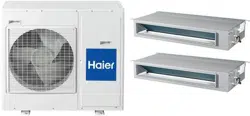
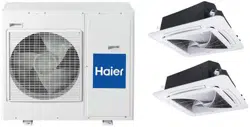
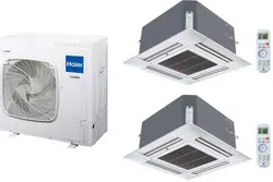
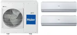
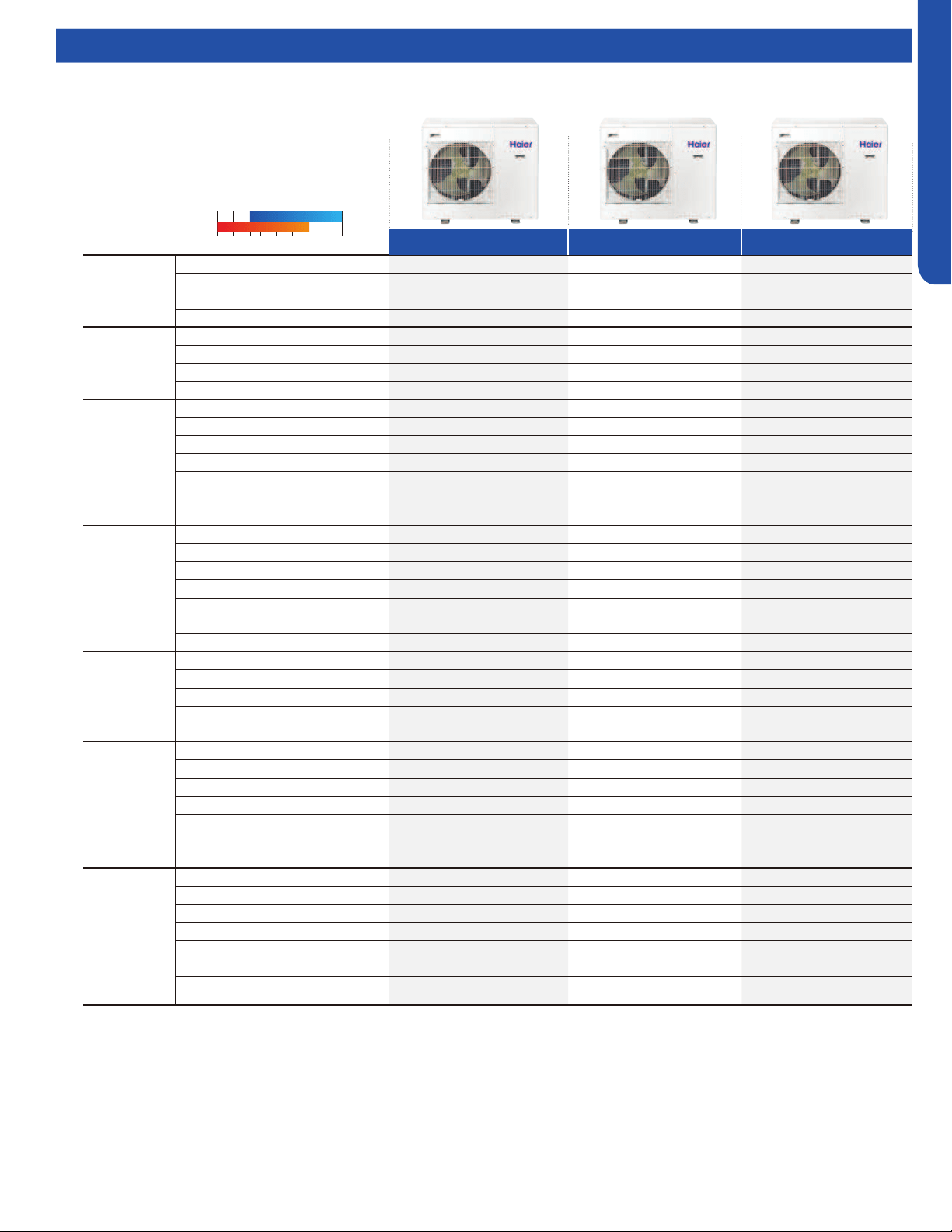
Outdoor
2U20EH2VHA
3U24EH2VHA
4U36EH2VHA
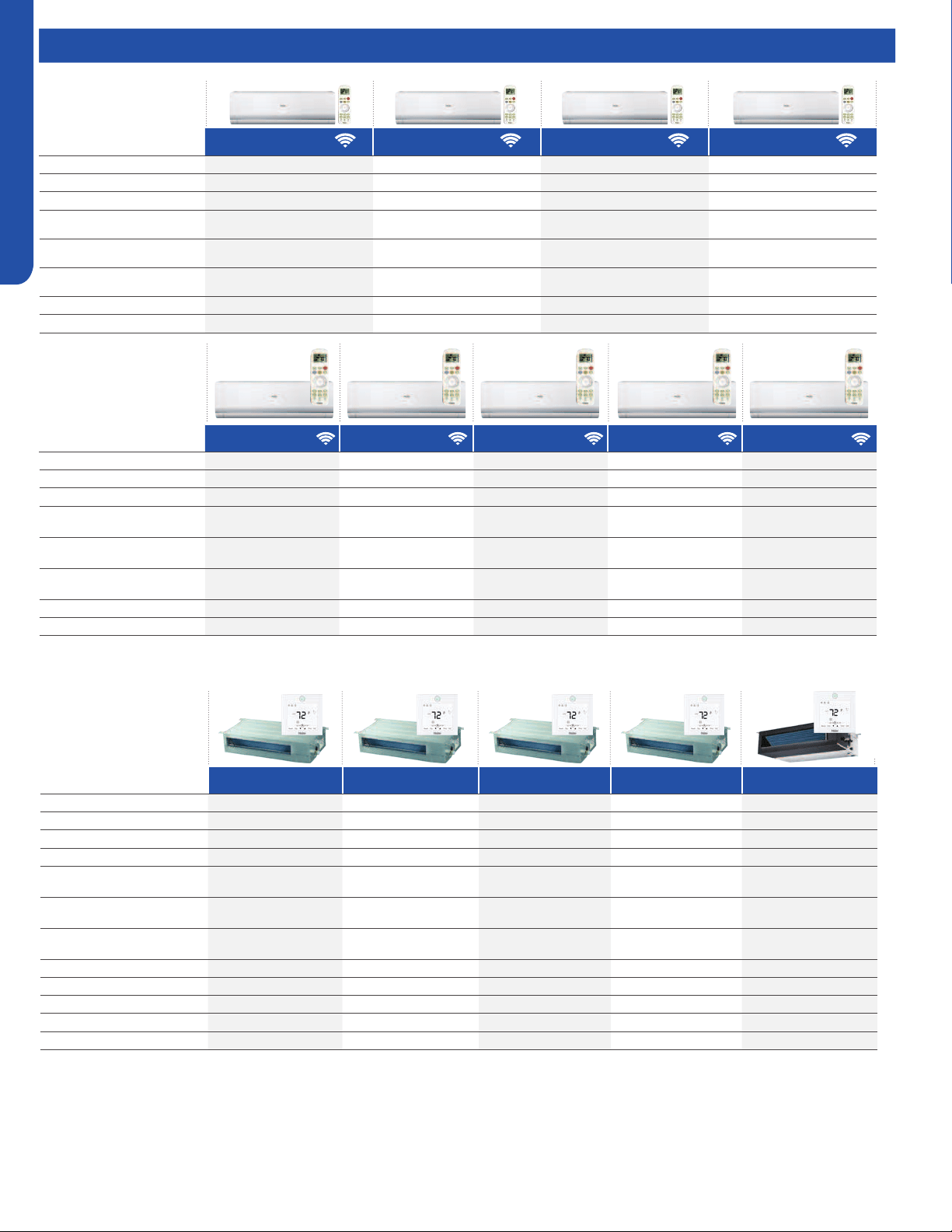
Indoor
Wall Mount - Highwall
AW07EH2VHA
AW09EH2VHA
AW12EH2VHA
AW18EH2VHA
AW07LC2VHB
AW09LC2VHB
AW12LC2VHB
AW18LC2VHB
AW24LP2VHA
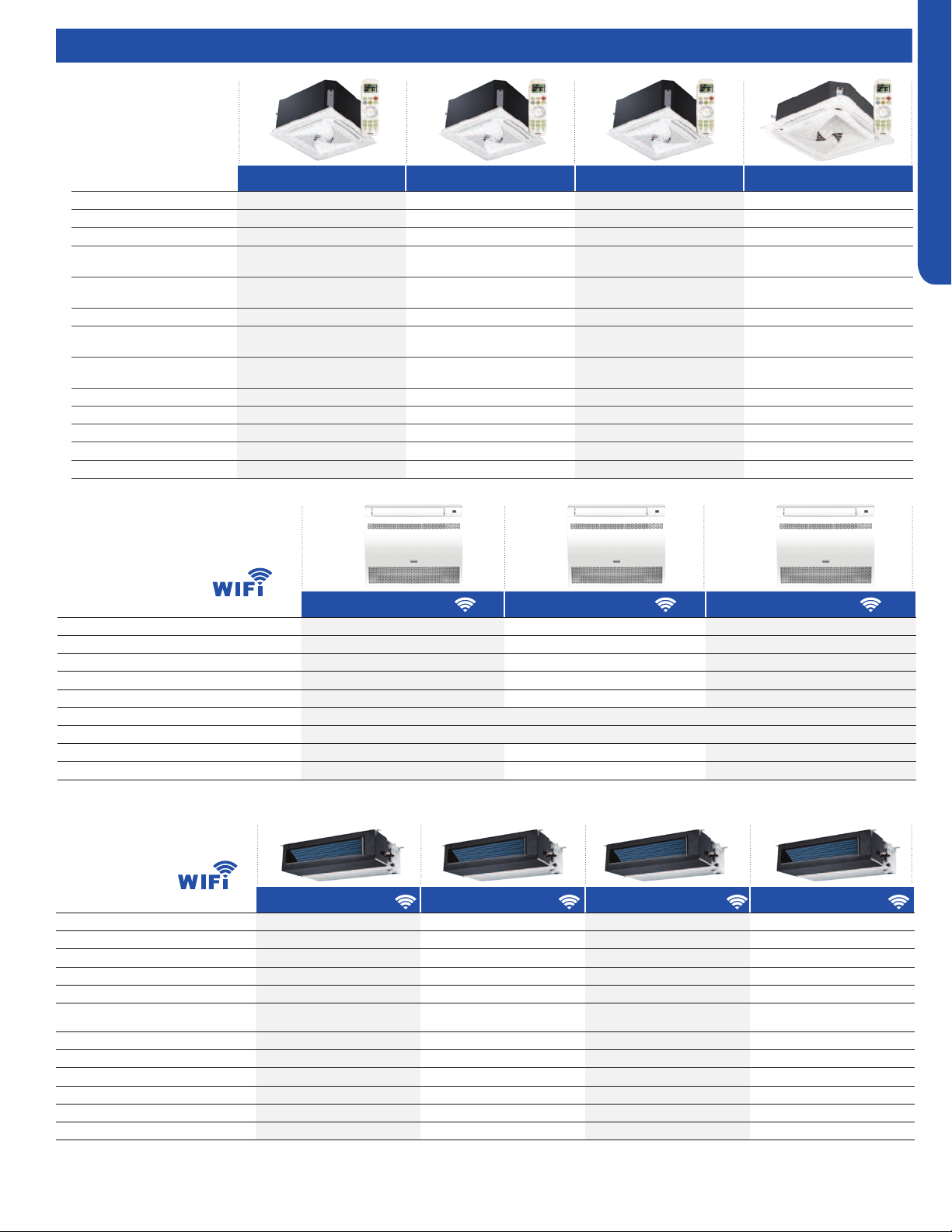
2’x2’ Compact Cassette
AB09SC2VHA
AB12SC2VHA
AB18SC2VHA
3’x3’ Large Cassette
AL24LP2VHA
Slim Duct
AD07SL2VHB
AD09SL2VHB
AD12SL2VHB
AD18SL2VHB
Mid-Static Ducted
USYM09UCDSA
USYM12UCDSA
USYM18UCDSA
USYM24UCDSA
Medium Static Ducted
AM24LP2VHA
Console
USYF09UCDWA
USYF12UCDWA
USYF18UCDWA
• Before troubleshooting or servicing equipment, review equipment installation guides
and conrm ALL installation requirements & specications have been met. Including,
but not limited to: wiring, clearance, ducting (where applicable), power, and line set
requirements. Correct any installation issues before continuing.

Aug. 2020 - Manual release.
Revision History

INTRODUCTION
A-1
ENGLISH
INTRODUCTION
Table of Contents
Safety & Precautions............................................................................................................................................................. A-2
Specications ....................................................................................................................................................................... A-3
Outdoor Units ..................................................................................................................................................................... A-3
Highwall Indoor ................................................................................................................................................................... A-4
Ducted Indoor ..................................................................................................................................................................... A-4
Cassette Indoor .................................................................................................................................................................. A-5
Console Indoor .................................................................................................................................................................... A-5
Mid-Static Ducted Indoor ................................................................................................................................................... A-5
Functions and Control ........................................................................................................................................................... A-6
Auto Mode ............................................................................................................................................................................ A-6
Cooling Operation Mode ..................................................................................................................................................... A-6
Dry Mode (Dehumidifying Mode) ........................................................................................................................................ A- 6
Heat Mode ............................................................................................................................................................................ A-7
Indoor Fan Control ............................................................................................................................................................... A-7
Cold Air-Proof Operation .................................................................................................................................................... A-7
Timing .................................................................................................................................................................................. A-7
Indoor System Mode Conict ............................................................................................................................................. A-7
Abnormality Conrmation Approaches ............................................................................................................................. A-8
Low Load Protection Control .............................................................................................................................................. A- 8
High Load Protection Control ............................................................................................................................................. A-8
When the Compressor First Starts ..................................................................................................................................... A-8
The Outdoor Fan Control (Exchange Fan) .......................................................................................................................... A-8
The Outdoor Fan Control When In Cooling or Dehumidifying Mode ................................................................................ A- 8
The Control of the Outdoor Unit Expansion Valve ............................................................................................................ A-8
Four-Way Valve Control ...................................................................................................................................................... A-8
Antifreezing Protection ....................................................................................................................................................... A-8
Over-Temperature Heat Mode Indoor Coil......................................................................................................................... A-9

Topic Title
INTRODUCTION
A-2
ENGLISH
Safety & Precautions
• Read these Safety Precautions carefully to ensure correct installation.
• This manual classies the precautions by WARNING and CAUTION.
• Follow all precautions below. They are all important for ensuring safety and preventing property/equipment damage.
!
WARNING: Failure to follow any of WARNING is likely to result in grave consequences such as death or serious injury.
!
CAUTION: Failure to follow any of CAUTION may, in some cases, result in grave consequences.
• The following safety symbols are used throughout this manual:
Observe this instruction
Establish an earth connection
Never attempt
• After completing installation, test the unit to check for installation errors. Give the user adequate instructions concerning the
use and cleaning of the unit according to the Operation Manual.
!
WARNING
• Installation should be performed by the dealer or another professional.
Improper installation may cause water leakage, electrical shock, or re.
• Install the heat pump according to the instructions given in this manual.
Incomplete installation may cause water leakage, electrical shock, or re.
• Use only the supplied or specied installation parts.
Use of other parts may cause the unit to come lose, water leakage, electrical shock, or re.
• Install the heat pump on a solid base that can support the unit’s weight.
An inadequate base or incomplete installation may cause injury in the event the unit falls o the base.
• Electrical work should be carried out in accordance with the installation manual and national/local electrical wiring codes and
rules of practice.
Insucient capacity or incomplete electrical work may cause electrical shock or re.
• Use a dedicated power circuit. Never use a power supply shared by another appliance.
• For wiring, use a cable long enough to cover the entire distance with no splices.
Do not use an extension cord. Do not put other loads on the power supply, use a dedicated power circuit.
(Failure to do so may cause abnormal heat, electric shock or re.)
• Use only the specied wire types for electrical connections between the indoor and outdoor units.
Firmly clamp the interconnecting wires so they receive no external stresses. Incomplete connections or clamping may cause terminal over-
heating or re.
• After completing interconnecting and supply wiring connections, shape the cables so that they do not put undue force on the
electrical covers or panels.
Install covers over the wires. Incomplete cover installation may cause terminal overheating, electrical shock, or re.
• If any refrigerant has leaked out during the installation work, ventilate the room.
(The refrigerant produces a toxic gas if exposed to ame.)
• After all installation is complete, check for and repair any system refrigerant leaks.
(The refrigerant produces a toxic gas if exposed to ames.)
•When installing or relocating the system, keep the refrigerant circuit free from substances other than the specied
refrigerant (R410A), such as air.
(The presence of air or other foreign substance in the refrigerant circuit causes an abnormal pressure rise or rupture, resulting in injury.)
• During pump-down, stop the compressor before removing the refrigerant piping.
If the compressor is still running, and the stop valve is open during pump-down, air will be sucked into the system while the compressor is
running. This will cause abnormal pressure and noncondensables added to the system.
• Be sure to establish a ground. Do not ground the unit to a utility pipe, arrester, or telephone earth.
An complete earth may cause electrical shock, or re. A high surge current from lightning or other sources may
cause damage to the heat pump.
!
CAUTION
• Do not install the heat pump in a place where there is danger of exposure to ammable gas.
If the gas builds up around the unit, it may catch re.
• Install drain piping according to the instructions of this manual.
Inadequate piping may cause ooding.
•Tighten the are nut according to the specied torque using a torque wrench.
If the are nut is overtightened, the are nut may eventually crack and cause refrigerant leakage.
• Provide adequate measures to prevent the outdoor unit from being used as a shelter by rodents.
Rodents making contact with electrical parts can cause malfunctions, smoke or re. Please instruct the customer to keep the area around
the unit clean.
Topic Title
INTRODUCTION
A-3
ENGLISH
Specications
2U20EH2VHA 3U24EH2VHA 4U36EH2VHA
Cooling
Non-Ducted
Rated Capacity Btu/hr 18,100 22,000 34,000
Capacity Range Btu/hr 7000-20000 6000-23600 6000-38000
Rated Power Input W 1448 1760 2,740
SEER/ EER 17/12.5 18.5/12.5 20 /12.5
Cooling Ducted
Rated Capacity Btu/hr 18,100 21,000 34,400
Capacity Range Btu/hr 6000-19000 6000-22300 6000-37000
Rated Power Input W 1724 2000 2,740
SEER/EER 15/10.5 15/10.5 17.00 /10.00
Heating
Non-Ducted
Rated Heating Capacity 47°F Btu/hr 20,000 24,000 36,000
Heating Capacity Range Btu/hr 8000-23000 8000-30600 8000-39000
Rated Power Input W 1504 1572 2,710
HSPF 10.5 10.5 10.5
COP @ 5°F 2.0 2.0 2.0
Max. Heating Capacity 5°F Btu/hr 23000 24000 36,000
Max. Heating Capacity -15°F Btu/hr 17000 18000 25,000
Heating Ducted
Rated Heating Capacity 47°F Btu/hr 20,000 22,000 35,000
Heating Capacity Range Btu/hr 8000-21000 8000-28600 8000-39000
Rated Power Input W 2255 2230 2710
COP/ COP @ 5°F 2.94/1.9 3/1.9 2.64/1.9
HSPF 9.6 9.3 10.5
Max. Heating Capacity 5°F Btu/hr 19000 20000 35,000
Max. Heating Capacity -15°F Btu/hr 15000 16000 25,200
Power Supply
Voltage, Cycle, Phase V/Hz/- 208-230/60/1 208-230/60/1 208-230/60/1
Wire Size between ID and OD 14/4 AWG Stranded 14/4 AWG Stranded 14/4 AWG Stranded
Compressor Type DC Inverter Driven Rotary DC Inverter Driven Rotary DC Inverter Driven Rotary
Maximum Fuse Size A 25 25 40
Minimum Circuit Amp A 15 16 30
Outdoor Unit
Outdoor Fan Speed RPM 300~900 300~900 300~900
Outdoor Noise Level dB 56 56 55
Dimension: Height in (mm) 33.1(840) 33.1(840) 38.0 (965)
Dimension: Width in (mm) 37.3(948) 37.3(948) 37.4(950)
Dimension: Depth in (mm) 13.4(340) 13.4(340) 14.6(370)
Weight (Ship/Net)- lbs (kg) 202.3/185.6 (91.7/84.2) 205.9/189.5 (93.4/85.9) 241/221 (109.7/100.6)
Connectable Indoor unit quantity 2 2 or 3 2 3 or 4
Refrigerant Lines
Connections Flare Flare Flare
Liquid O.D. in 1/4 1/4 1/4 1/4 1/4 1/4 1/4 1/4
Suction O.D. in 3/8 3/8 3/8 3/8 1/2 3/8 3/8 3/8 1/2
Factory Charge Oz 99 99 113
Maximum Line Length Ft / m 164/50 196/60 230/70
Maximum Height Ft / m 50/15 50/15 50/15
Maximum Line Length for each individual
indoor unit Ft / m
82/25 82/25 82/25
2 Zones 3 Zones 4 Zones
Compressor Type:
DC Inverter Driven Rotary
Voltage/Cycle/Phase:
208-230/60/1
Operating Range (
O
F):
-22 1151450-4
-15
Cooling
Heating
75
Outdoor Units
Topic Title
INTRODUCTION
A-4
ENGLISH
Specications
AW07EH2VHA AW09EH2VHA AW12EH2VHA AW18EH2VHA
Rated Cooling Capacity Btu/hr 7,000 9,000 12,000 19,000
Rated Heating Capacity Btu/hr 10,000 12,000 16,500 20,400
Voltage, Cycle, Phase V/Hz/- 208-230/60/1 208-230/60/1 208-230/60/1 208-230/60/1
Airow CFM
(Turbo/H/M/L/Quiet)
420/360/300/240/180 470/410/350/290/230 440/410/380/311/260 710/650/560/440/410
Indoor Sound dB
(Turbo/H/M/L/Quiet)
42/39/37/28/23 42/39/37/28/23 42/39/37/28/23 49/47/42/36/34
Dimension: H x W x D in (mm)
12 1/4 x 35 3/8 x 8 1/4
(310 x 900 x 210)
12 1/4 x 35 3/8 x 8 1/4
(310 x 900 x 210)
12 1/4 x 35 3/8 x 8 1/4
(310 x 900 x 210)
14 3/8 x 43 7/8 x 9 5/8
(336 x 1115 x 243)
Weight (Ship/Net)- lbs (kg) 30.9/25.3 (14/11.5) 30.9/25.3 (14/11.5) 30.9/25.3 (14/11.5) 45.4/37.5 (20.6/17)
Liquid /Suction O.D. in 1/4 3/8 1/4 3/8 1/4 3/8 1/4 1/2
AD07SL2VH(-) AD09SL2VH(-) AD12SL2VH(-) AD18SL2VH(-) AM24LP2VH(-)
Rated Cooling Capacity Btu/hr 7,000 9,000 12,000 18,000 24000
Rated Heating Capacity Btu/hr 8,000 10,000 13,000 19,000 27000
Voltage, Cycle, Phase V/Hz/- 208-230/60/1 208-230/60/1 208-230/60/1 208-230/60/1 208-230/60/1
Airow CFM (Turbo/H/M/L/Quiet) 353/312/270/230/188 353/312/270/230/188 400/353/282/247/218 540/500/447/365/306 845/670/530/470
Max. Ext. Static Pressure
in.W.G (Pa)
0.16 (40) 0.16 (40) 0.16 (40) 0.16 (40) 0.6 (150)
Indoor Sound dB
(Turbo/H/M/L/Quiet)
35/33/29/26/21 35/33/29/26/22 38/35/29/26/23 31/29/23/29/25 38/35/32/29
Dimension: HxWxD in (mm)
7 5/16 x 33 7/16 x16 9/16
(185x850x420)
7 5/16 x 33 7/16 x16 9/16
(185x850x420)
7 5/16 x 33 7/16 x16 9/16
(185x850x420)
7 5/16 x 46 1/16 x16 9/16
(185x1170x420)
9 7/8 x 37 5/8 x 25 3/4
(250x957x655)
Weight (Ship/Net)- lbs (kg) 47.2/36.8 (21.4/16.7) 47.2/36.8 (21.4/16.7) 47.2/36.8 (21.4/16.7) 61.8/48.5 (28/22) 68.8/81.1 (31.2/36.8)
Liquid / Suction O.D. in 1/4 3/8 1/4 3/8 1/4 3/8 1/4 1/2 3/8 5/8
Drainpipe Size O.D. in 1 1/4 1 1/4 1 1/4 1 1/4 1 1/4
Condensate Pump Standard Standard Standard Standard Standard
Max. Drain-Lift height in(mm) 27 9/16 (700) 27 9/16 (700) 27 9/16 (700) 27 9/16 (700) 27 9/16 (700)
AW07LC2VH(-) AW09LC2VH(-) AW12LC2VH(-) AW18LC2VH(-) AW24LP2VH(-)
Rated Cooling Capacity Btu/hr 7,000 9,000 12,000 18,000 22,000
Rated Heating Capacity Btu/hr 8,000 10,000 13,000 19,000 24,000
Voltage, Cycle, Phase V/Hz/- 208-230/60/1 208-230/60/1 208-230/60/1 208-230/60/1 208-230/60/1
Airow CFM
(Turbo/H/M/L/Quiet)
410/350/295/235/205 410/350/295/235/205 440/380/320/265/215 636/530/483/430/383 710/650/560/440/410
Indoor Sound dB
(Turbo/H/M/L/Quiet)
43/38/33/26/22 43/38/33/26/22 44/39/34/27/23 48/45/40/35/30 49/47/42/36/34
Dimension: H x W x D in (mm)
11 x 33 5/8 x 8 1/16
(280 x 855 x 204)
11 x 33 5/8 x 8 1/16
(280 x 855 x 204)
11 x 33 5/8 x 8 1/16
(280 x 855 x 204)
12 3/4 x 39 1/4 x 9 1/4
(332 x 997 x 235)
13 1/4 x 43 7/8 x 9 9/16
(336 x 1115 x 243)
Weight (Ship/Net)- lbs (kg) 26.8/22 (12.2/10) 26.8/22 (12.2/10) 26.8/22 (12.2/10) 35.3/28.6 (16/13) 45.4/37.5 (20.6/17)
Liquid /Suction O.D. in 1/4 3/8 1/4 3/8 1/4 3/8 1/4 1/2 3/8 5/8
Highwall Indoor
Ducted Indoor
Topic Title
INTRODUCTION
A-5
ENGLISH
Specications
AB09SC2VH(-) AB12SC2VH(-) AB18SC2VH(-) AL24LP2VH(-)
Rated Cooling Capacity Btu/hr 9,000 12,000 18,000 24200
Rated Heating Capacity Btu/hr 10,000 13,000 19,000 27300
Voltage, Cycle, Phase V/Hz/- 208-230/60/1 208-230/60/1 208-230/60/1 208-230/60/1
Airow CFM
(Turbo/H/M/L/Quiet)
410/365/305/265/205 410/365/305/265/205 470/410/365/295/252 740/630/480/400
Indoor Sound dB
(Turbo/H/M/L/Quiet)
42/40/36/32/25 42/40/36/32/25 45/42/40/36/32 38/35/32/29
Grille Model PB-700KB PB-700KB PB-700KB PB-950KB
Chassis Dimension:
HxWxD in (mm)
10 1/4 x 22 7/16 x 2 3/8
(260 x 570 x 570)
10 1/4 x 22 7/16 x 2 3/8
(260 x 570 x 570)
10 1/4 x 22 7/16 x 2 3/8
(260 x 570 x 570)
9 5/8 x 33 1/8 x 33 1/8 (246 x 840
x840)
Grille Dimension: HxWxDin (mm)
2 3/8 x 27 9/16 x 27 9/16
(60 x 700 x 700)
2 3/8 x 27 9/16 x 27 9/16
(60 x 700 x 700)
2 3/8 x 27 9/16 x 27 9/16
(60 x 700 x 700)
2 x 3 1/8 x 3 1/8
(50 x 950 x 950)
Weight (Ship/Net)- lbs (kg) 46.3/37.5 (21/17) 46.3/37.5 (21/17) 46.3/37.5 (21/17) 68.4/79.4 (31/36)
Liquid / Suction O.D. in 1/4 3/8 1/4 3/8 1/4 1/2 3/8 5/8
Drainpipe Size O.D. in 1 1/4 1 1/4 1 1/4 1
Condensate Pump Standard Standard Standard Standard
Max. Drain-Lift height in(mm) 27 9/16 (700) 27 9/16 (700) 27 9/16 (700) 47 1/4(1200)
Cassette Indoor
USYF09UCDWA USYF12UCDWA USYF18UCDWA
Rated Cooling Capacity Btu/hr 9,000 12,000 15,000
Rated Heating Capacity Btu/hr 10,000 13,000 18,000
Voltage, Cycle, Phase V/Hz/- 208-230/60/1 208-230/60/1 208-230/60/1
Airow (Turbo/High/Med/Low/Quiet) CFM 264/235/205/176/147 294/264//205/176/147 341/311/282/252/223
Indoor Sound Level dB (Turbo/High/Med/Low/Quiet) 40/32/25/20 42/34/26/21 46/37/33/28
Chassis Dimension: HxWxD in (mm) 23.6/27.5/8.3 (600/700/210)
Weight (Ship/Net)- lbs (kg) 36/40 (16.5/18.5)
Liquid / Suction O.D. in 1/4 3/8 1/4 3/8 1/4 1/2
Drainpipe Size O.D. in 1 1/4 1 1/4 1 1/4
Built-in WiFi
Console Indoor
Mid-Static Ducted Indoor
USYM09UCDSA USYM12UCDSA USYM18UCDSA USYM24UCDSA
Rated Cooling Capacity Btu/hr 9,000 12,000 18,000 24000
Rated Heating Capacity Btu/hr 10,000 13,000 19,000 25000
Voltage, Cycle, Phase V/Hz/- 208-230/60/1 208-230/60/1 208-230/60/1 208-230/60/1
Airow (Turbo/High/Med/Low/Quiet) CFM 494/423/352/264 494/423/352/264 635/529/458/388 845/670/530/470
Max. External Static Pressure in.W.G (Pa) 0.6 (150) 0.6 (150) 0.6 (150) 0.6 (150)
Indoor Sound Level dB
(Turbo/High/Med/Low/Quiet)
35/32/29/26 35/32/29/26 37/34/32/29 39/36/33/30
Chassis Dimension: HxWxD in (mm) 27.5/27.5/9.7(700/700/248) 27.5/27.5/9.7(700/700/248) 43.3/27.5/9.7(1100/700/248) 43.3/27.5/9.7(1100/700/248)
Weight (Ship/Net)- lbs (kg) 57/66(26/30) 57/66(26/30) 70/77 (32/35) 70/77 (32/35)
Liquid / Suction O.D. in 1/4 3/8 1/4 3/8 1/4 1/2 3/8 5/8
Drainpipe Size O.D. in 1 1/4 1 1/4 1 1/4 1 1/4
Condensate Pump Standard Standard Standard Standard
Max. Drain-Lift height in(mm) 39(1000) 39(1000) 39(1000) 39(1000)
Built-in WiFi

INTRODUCTION
A-6
ENGLISH
Functions and Control
Auto Mode
When the running mode is turned to auto after starting the
system, the system will rst determine the running mode
according to the current room temperature and then will
run according to the determined mode: Tr means room
temperature; Ts means temperature setting; Tp means
temperature of indoor coil pipe
Tr≥73°F Choose Cooling Mode
Tr<73°F Choose Heating Mode
After turning to the auto mode, the running mode will be
switched between cooling mode, fan mode, and heating mode
according to the change of the indoor ambient temperature.
There is a 15 minute delay between mode changes.
Cooling Operation Mode
Temperature control range: 60°F---86°F
Temperature dierence: ±2°F
• Control features: When Tr (input airow)>Ts (set
temperature) °F, the indoor fan will operate at the set speed,
the mode signal will be sent to the outdoor system, and
the compressor will start. When Tr (input airow)< Ts (set
temperature)°F, the indoor fan will operate at the set speed,
and the mode signal will be sent to the outdoor system, and
the compressor will stop. The system will keep the original
status if Tr= Ts.
Airow speed control: (temperature dierence ±2°F)
Automatic:
When Tr≤Ts +4°F high speed.
When Ts+2°F≤Tr<Ts+5°F, medium speed
When Tr<Ts+2°F, low speed
When the sensor is o, low speed
When the airow speed has no delay from the high to low
switching, the speed should be delayed for 3 minutes (remain
at high speed for 3 minutes.) before the next switch.
When the system is operating, you can set the high, medium
or low speed manually. (When the sensor is on or o, the
system will change the speed 2 seconds after receiving the
signal.)
• Louver control: the location for the louver can be set
according to your needs.
• Defrosting function: preventing the frosting on the indoor
heat exchanger (when cooling or dehumidifying). When
the compressor works continuously for 1 to 6 minutes
(adaptable in EEPROM) and the temperature of the indoor
coils has been below 32°F for 10 seconds, the compressor
will be stopped and the malfunction will be recorded in the
malfunction list. The indoor system will continue to run.
When the temperature of the indoor coil is raised to 45°F,
the compressor will be restarted again (the requirement of 3
minutes’ delay should be satised.)
Dry Mode (Dehumidifying Mode)
• Temperature control range: 60-86°F
• Temperature dierence: ±2°F
Control feature: Send the dehumidifying signal to the outdoor
system.
When Tr>Ts+4°F, the compressor will be turned on, the indoor
fan will operate at the set speed. When Tr is between the
Ts and Ts+4°F, the outdoor system will operate at the high
dehumidifying frequency for 10 minutes and then at the low
dehumidifying mode for six minutes. The indoor fan will
operate at low speed.
When Tr< Ts, the outdoor system will be stopped, the indoor
fan will be stopped for 3 minutes and then turned to the low
speed option.
All the frequency conversions have a ±2°F dierence.
• Wind speed control: Automatic:
When Tr≥ Ts+ 9°F, high speed.
When Ts+5°F≤Tr< Ts+9°F, medium speed.
When Ts+4°F≤Tr< Ts+5°F, low speed.
When Tr<Ts+4°F, light speed.
If the outdoor fan is stopped, the indoor fan will be paused for
3 minutes.
If the outdoor fan is stopped for more than 3 minutes and the
outdoor system still operates, the system will be changed into
light speed mode.
When the airow speed has no delay from the high to low
switching, the speed should be delayed for 3 minutes (remain
at high speed for 3 minutes) before the next switch.
When the sensor is o or Tr< Ts+5°F, the manual operation can
not be made (obligatory automatic operation).
• Louver location control: the location for the louver can be
set according to your needs.
• Defrosting function: preventing the frosting on the
indoor heat exchanger (when cooling or dehumidifying).
When the compressor works continuously for 16 minutes
(adaptable in EEPROM) and the temperature of the indoor
coils has been below 32°F for 10 second, the compressor
will be stopped and the malfunction will be recorded in the
malfunction list. The indoor system will continue to run.
When the temperature of the indoor coil is raised to 45°F,
the compressor will be restarted again (the requirement of 3
minutes’ delay should be satised.)
INTRODUCTION
A-7
ENGLISH
Functions and Control
Heat Mode
• Temperature control range: 60-86°F
• Temperature dierence: ±2°F
Control feature: the temperature compensation is
automatically added and the system will send the heating
signals to the outdoor system.
If Tr≤Ts, the outdoor compressor is turned on, the indoor fan
will be at the cold air proof mode.
If Tr>Ts+, the outdoor system is turned o, the indoor fan will
be at the heat residue sending mode.
If Tr<Ts+, the outdoor system will be turned on again, the
indoor fan will be in the cold air proof mode.
Indoor Fan Control
Manual Control: You can choose high, medium, low and
automatic speed control. Automatic:
When Tr<Ts, high speed.
When Ts≤Tr≤Ts+4°F, medium speed.
When Tr> Ts+4°F, low speed.
When the airow speed has no delay from the high to low
switching, the speed should be delayed for 3 minutes (remain
at high speed for 3 minutes.) before the next switch.
• Louver location control: the location for the louver can be
set according to your needs.
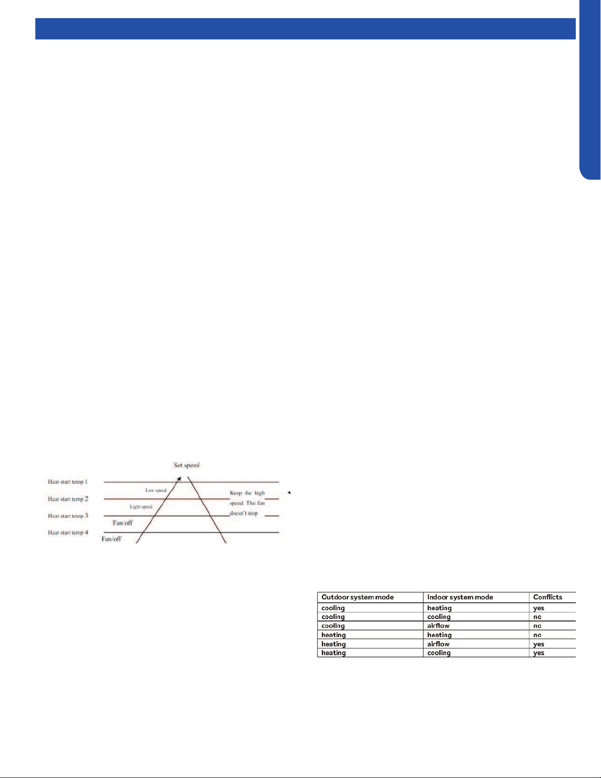
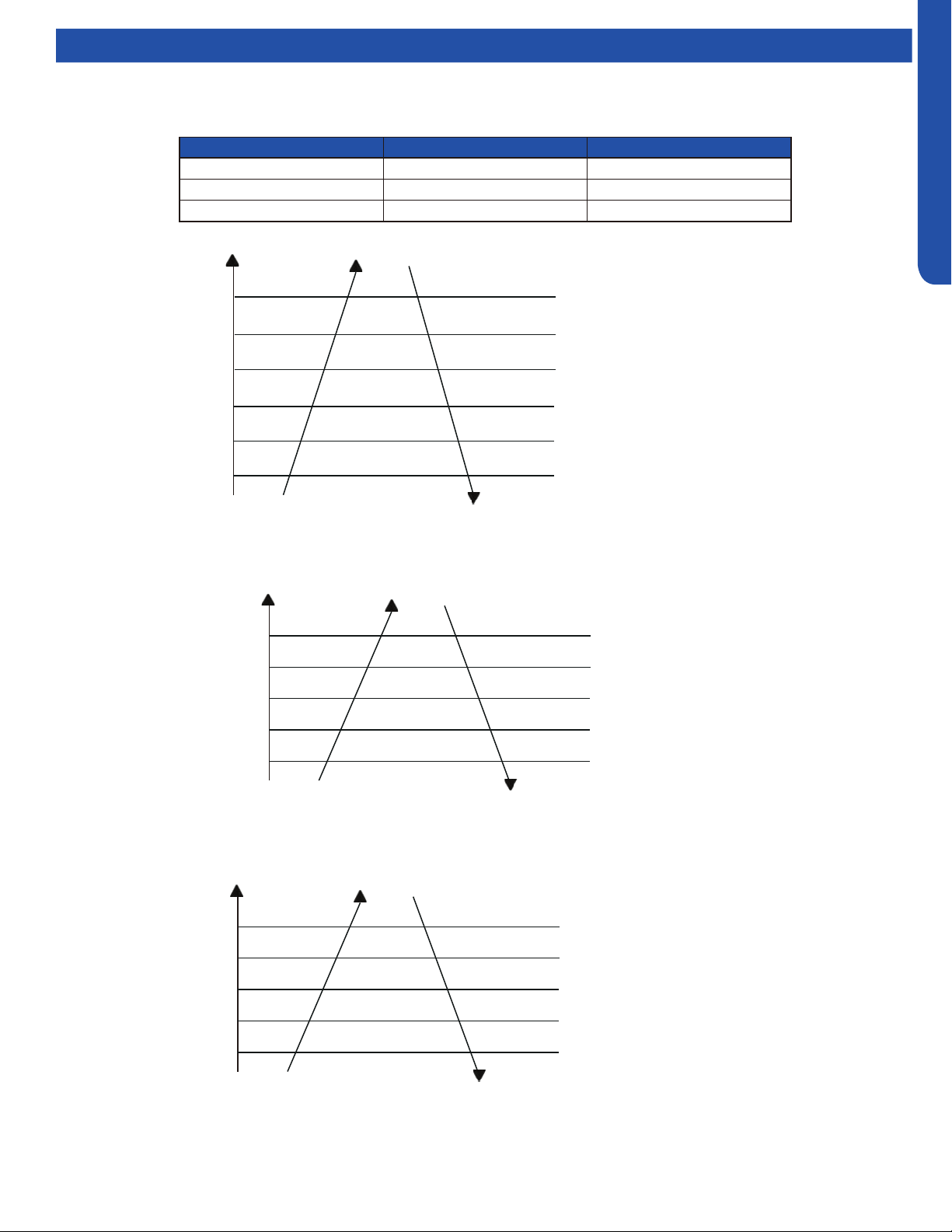
Cold Air-Proof Operation
1. The indoor operation within 4 minutes after the start up is
as the following diagram, the air speed can be raised only
after the speed has reached a certain level.
• Residue heat sending. The indoor fan will send the residue
heat at a low speed for 12 seconds.
• If other conditions are satised, when the compressor stops,
the indoor system will operate at a light speed. The indoor
fan will stop when the coil temperature is below the heat
start temp 4’.
• Defrosting. When the system receives the defrosting signal
from outdoors, the indoor fan will stop and the indoor
temperature display won’t change. At this time, any indoor
coil malfunctions will be neglected. When the outdoor
defrosting nishes, the coil malfunction will still be neglected
until the compressor has been started up for 30 seconds.
The indoor temperature display will not change and the
system operates at the cold air proof mode.
• Automatic heating temperature compensation: when
the system enters the heating mode, the temperature
compensation (4) will be added. When the status is switched
o, the compensation will be erased.
Timing
You can set 24 hours on/o timing. After setting, the timing
indicator will be displayed. Also, the light will turn o after the
timing is set. The followings are several timing methods:
1. System ON timing: The timing indicator will be displayed
and the indoor system is under the waiting mode. The light
will be turned o when the timing is nished and the rest
of the system will operate under a normal condition. The
timing starts since the last reception of the timing signal.
2. System /OFF timing: When the system is turned on, the
timing indicator will be displayed; the rest of the system
will operate under normal conditions. When the set time
expires, the indicator display will turn o and the system
will turn o. If you have set the dormant functions, the
order of your settings will be operated according to the
timing settings.
3. System ON/OFF timing: The settings will be completed
according to the settings.
2. 4 minutes after the start up of the indoor fan, the light
airow and the low airow will be turned to the set speed
airow.
3. In the cold air proof operation, the fan won’t stop after the
start up.
4. During the cold air proof operation, the indoor system
will continuously send ‘indoor high speed’ signals to the
outdoor system.
Indoor System Mode Conict
The indoor unit is trying to operate in a mode that is opposite
of the mode the outdoor unit is currently operating in. Change
the operating mode to either heat or cool, or the indoor unit
will shut o.

INTRODUCTION
A-8
ENGLISH
Functions and Control
Abnormality Conrmation Approaches
1. Indoor temperature sensor abnormality:
Under the operation, the normal temperature ranges from
120°F to -30°F. When the temperature goes beyond this
range, the abnormality can be conrmed. If the temperature
goes back into the range, the system will automatically
resume.
2. Indoor heat interaction sensor abnormality:
Under the operation, the normal temperature ranges from
120°F to -30°F. When the temperature goes beyond this
range, the abnormality can be conrmed. If the temperature
goes back into the range, the system will automatically
resume.
3. Indoor/Out door malfunction:
When the indoor system receives the outdoor malfunction
codes, it will store the code into E2 for the malfunction list
resume. The indoor system will continue to operate according
to the original status, the malfunction code will not be
revealed or processed.
4. Transmission abnormality:
If the indoor system can’t receive the outdoor system for 8
minutes, the communication abnormality can be conrmed
and reported and the outdoor system will be stopped.
Low Load Protection Control
In order to prevent the frosting of the indoor heat interaction
device, the outdoor system will be stopped if the indoor heat
interaction temperature is 32°F for 5 minutes, but the fan will
continue to operate. The outdoor system will be started again
when the heat interaction temperature is above 108°F, and the
system has been stopped for 3 minutes. The malfunction will
be stored in the malfunction resume and will not be revealed.
High Load Protection Control
The outdoor system will be stopped if the coil temperature is
above 149°F for 2 minutes. The indoor fan will be controlled by
the thermostat. The outdoor system can be restarted when
the coil temperature is below 108°F and the system has been
stopped for 3 minutes. The malfunction will be stored in the
malfunction resume and will not be revealed.
When the Compressor First Starts
The compressor will start in low frequency. After a brief time
delay, the compressor will come up to operating speed to
meet the demand requirement for capacity.
The Outdoor Fan Control (Exchange Fan)
When adjusting the fan speed, the unit should remain at each
speed for 30+ seconds to avoid speed-change malfunctions.
In Cooling Mode, the wait time between speed levels should
be 15 seconds.
The Outdoor Fan Control When In Cooling or
Dehumidifying Mode
Five seconds after compressor starts, the outdoor fan will
start running at medium speed. After 30 seconds, it begins to
control the fans peed according to the temperature conditions
of the outdoor environment.
The Control of the Outdoor Unit Expansion Valve
When unit starts, the EEV valves will energize and change to a
standard opening. When operation starts, the EEV will change
position to keep the suction vapor superheat level at around
10°F.
When the unit is shut o the opening size of the expansion
valve of the indoor unit is 5 steps;
Four-Way Valve Control
For the details of defrosting four-way valve control, see the
defrosting process.
Under heating mode, the four-way valve opens. If the
compressor does not start or changes to a non-heating
mode, the compressor will be stopped for 2 minutes, and then
the four-way valve will shift.
Antifreezing Protection (Highwall Only)
Prevents freeze-up of the indoor coil
The indoor unit coil temperature sensor will shut o the
outdoor unit and begin a defrosting routine if the indoor coil
is below 32°F for more than 2 minutes. The indoor unit will
not report this operation. Once the indoor coil warms up, the
system will re-enter cooling mode and operate normally, This
protection cycle prevents the indoor coil from developing ice
coating during low heat load operation.
INTRODUCTION
A-9
ENGLISH
Functions and Control
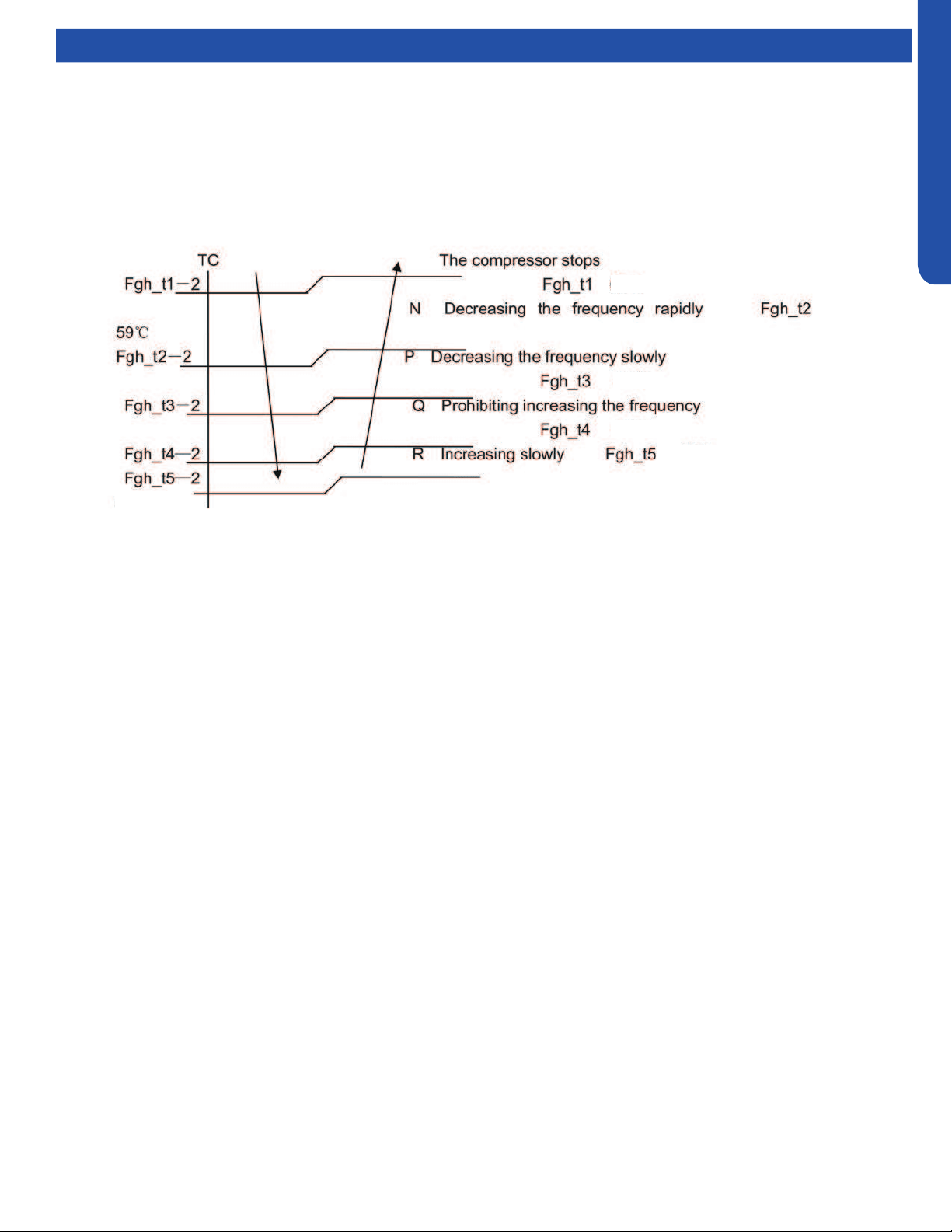
Over-Temperature Heat Mode Indoor Coil
The over-temperature routine will protect the system from excessive high indoor coil temperature during heat mode operation.
The routine will initiate if the indoor coil temperature sensor reads temperatures in excess of 131F. Conditions that cause high
indoor coil temperature include indoor fan failure, dirty indoor coil and operating the system in heat mode when outdoor air
temperatures exceed operating limit. (Too warm outside)
Should this routine be initiated, the system will reduce compressor frequency until the indoor coil temperature reaches 117F.
Once this is achieved, the system will return to normal operation.
149°F
131°F
138°F
117°F
124°F

[This page intentionally left blank.]
OUTDOOR TECHNICAL OVERVIEW
B-1
ENGLISH
OUTDOOR TECHNICAL OVERVIEW
Components ......................................................................................................................................................................... B-2
Component Overview ......................................................................................................................................................... B-2
Service Monitor Board (SMB) .............................................................................................................................................. B-3
Inverter Power Module (IPM) ............................................................................................................................................... B-3
PCB ....................................................................................................................................................................................... B-4
Power Filter Board (PFB) ...................................................................................................................................................... B-5
Operations............................................................................................................................................................................ B-6
Cooling Mode Sequence of Operation ............................................................................................................................... B-6
Heating Mode Sequence of Operation ............................................................................................................................... B-8
Defrost Cycle Sequence of Operation ............................................................................................................................. B-10
Electronic Expansion Valve (EEV) Control ........................................................................................................................ B-11
4-Way Valve Heating Control ............................................................................................................................................ B-11
Compressor Sump Heater ................................................................................................................................................ B-11
Defrost Control .................................................................................................................................................................. B-12
Base Pan Heater Control Logic ......................................................................................................................................... B-12
Troubleshooting the Base Pan Heater Error .................................................................................................................... B-12
Discharge Sensor Protection ............................................................................................................................................ B-12
High Current Protection .................................................................................................................................................... B-13
High Pressure Protection in Cooling ................................................................................................................................. B-13
High Pressure Protection In Heating ................................................................................................................................ B-13
Low Pressure Protection ................................................................................................................................................... B-14
Oil Return Cycle ................................................................................................................................................................. B-15
Testing ................................................................................................................................................................................ B-16
Outdoor Fan Motor ............................................................................................................................................................ B-16
Temperature Sensor .......................................................................................................................................................... B-16
4-Way Valve ....................................................................................................................................................................... B-17
Electronic Expansion Valve (EEV) ..................................................................................................................................... B-17
Variable Speed Compressor ............................................................................................................................................. B-18
Wiring Error Check ............................................................................................................................................................. B-18
Wiring Diagrams ................................................................................................................................................................. B-19
DIP Switch Settings ............................................................................................................................................................ B-22
Error Codes ......................................................................................................................................................................... B-24
Table of Contents
2U20EH2VHA
3U24EH2VHA
4U36EH2VHA
OUTDOOR TECHNICAL OVERVIEW
B-2
ENGLISH
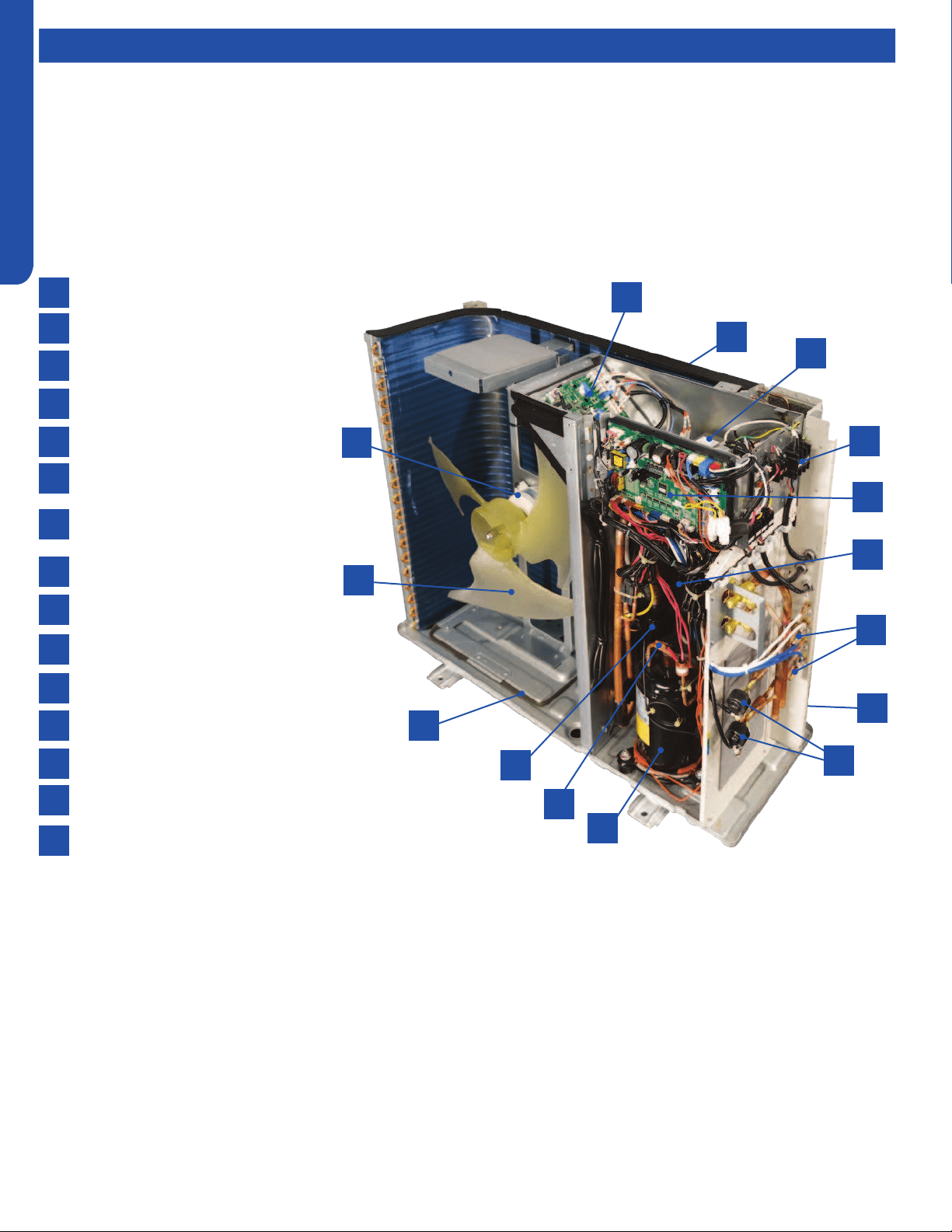
Topic TitleComponents
The outdoor unit features a variable speed, rotary type compressor that delivers refrigerant ow to up to 4 individual indoor
units. The system uses R-410A refrigerant mixed with PVE oil, and is 208/230 VAC, 60 Hz, single phase.
Compatible indoor units are High wall, Cassette, Ducted, and Console with remote control, cassette with either remote or wired
control, and ducted with wired control only.
The indoor units will maintain individualized room temperatures as set on each controller, provided all units are in the same
mode. If the rst unit to be turned on is set to the heating mode, all units will heat. If the rst unit to be turned on is set to the
cooling mode, all units will cool.
1
2
3
4
5
6
7
8
9
10
11
12
13
14
15
4-Way Valve
Accumulator
Compressor
Defrost Temperature Sensor
Discharge Temperature Sensor
Electronic Expansion Valves
Outdoor Ambient Temperature
Sensor
Outdoor Fan Motor
Power Factor Reactor
Suction Line Temperature Sensors
Terminal Block
Main Control Board
Module Control Board
Fan Blade
Base Pan Heater
Component Overview
6
11
3
15
2
5
8
14
7
1
12
13
9
4
10
OUTDOOR TECHNICAL OVERVIEW
B-3
ENGLISH
Topic TitleComponents
2
4
3
1
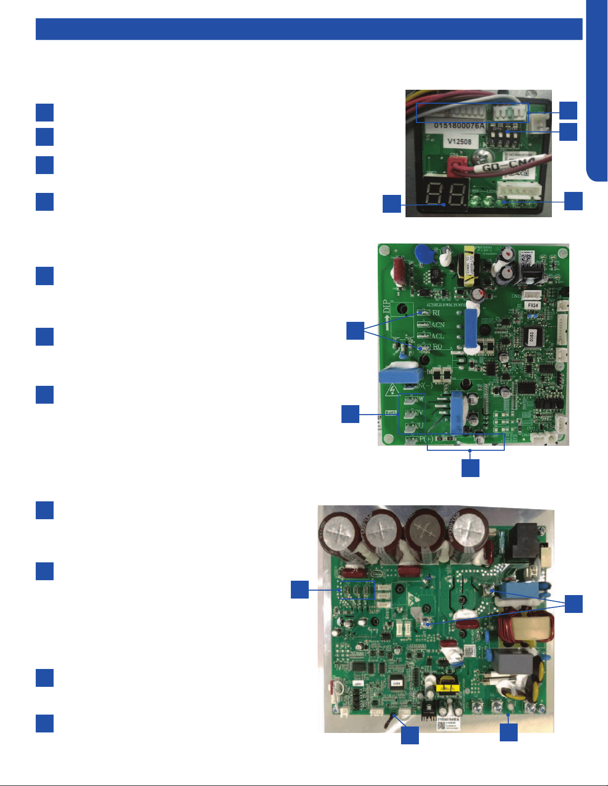
The SMB is connected to the PCB via connections CN-2 and CN-3.
The SW1 DIP switches are OFF (default position for normal operation).
The digital display will indicate operating frequency of the compressor when no
error code is present, or will ash an error code if present.
A solid green LED indicates that the A, B, C, D or E unit is successfully
communicating with the outdoor unit.
The SMB has important features including operational DIP switches, error code display, compressor speed, and diagnostic
capabilities.
2
4
1
3
2
3
1
The Inverter Power Module generates 3-phase VDC
power to operate the variable speed compressor. The
compressor is connected to the IPM via terminals U, V
and W.
A Reactor Coil is connected to the IPM at terminals
RI and RO. The Reactor Coil will lter electrical noise
generated at high frequency operation that could
cause damage to the compressor windings.
IPM generates a large amount of heat during operation.
This heat is transfered to a heat sink behind the board,
then mixed with the outdoor air. The Tm temperature
sensor protects the IPM from excessive temperatures.
2
1
3
Service Monitor Board (SMB)
Inverter Power Module (IPM)
2U & 3U
2
3
4
1
1
4U
The Inverter Power Module generates 3-phase
variable VDC power(60V-230V) to operate the
variable speed compressor. The compressor is
connected to the IPM via terminals U, Vand W.
A Reactor Coil is connected to the IPM at terminals
LI and LO.The Reactor (spec is 5mH,25A/5mH);
the reactor is one part of the PFC(power factor
chopper circuit). Its main function is to boost
the DC bus voltage with the PFC switches IGBT.
The PFC circuit will improve the power factor
and reduce electromagnetic noise caused by
harmonics.
IPM generates a large amount of heat during
operation. This heat is transferred to a heat sink
behind the board, then mixed with the outdoor air.
The Tn temperature sensor is used to protects
the IPM from excessive temperatures.
2
3
4
OUTDOOR TECHNICAL OVERVIEW
B-4
ENGLISH
Components
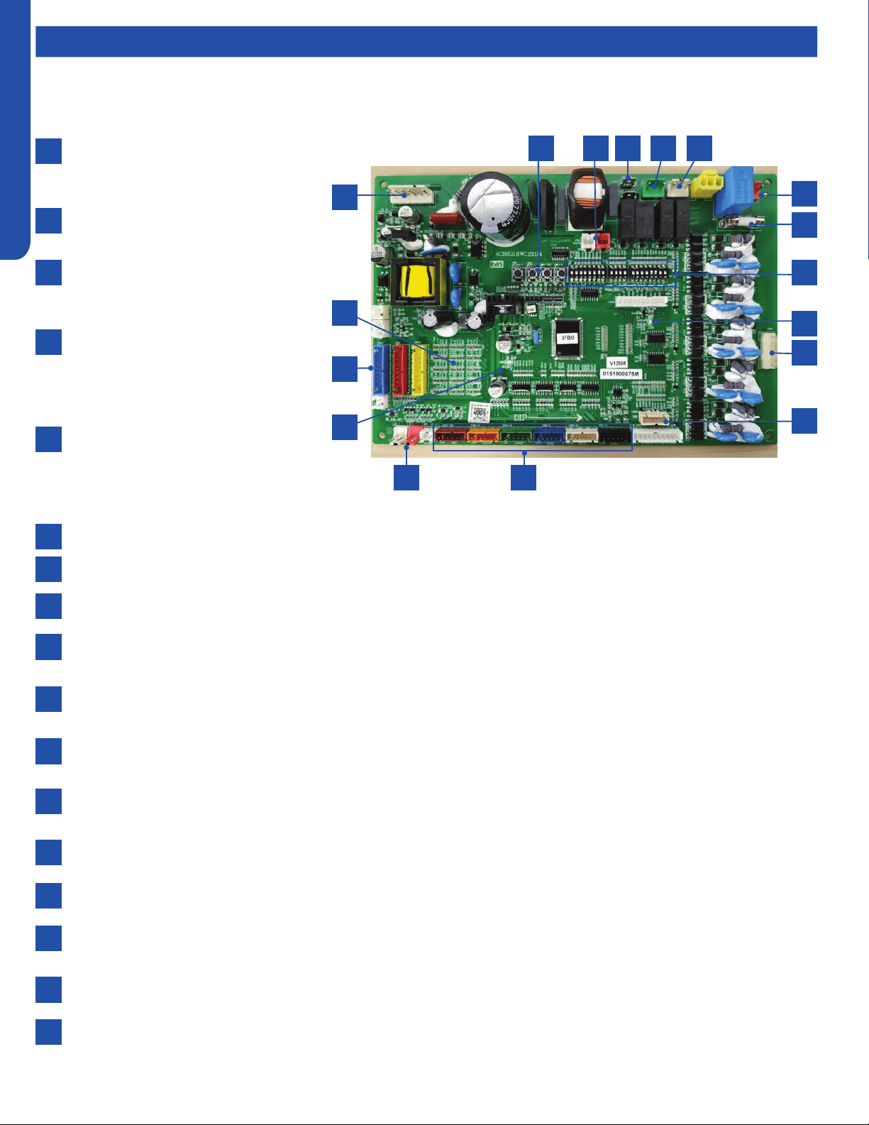
Voltage to operate the PCB is provided by
the Power Filter Board on terminals ACN
and ACL.
When power is present, the Green LED
will light.
The communication cables to the PCB
from the Power Filter Board connect to
CN6 and CN34.
The Service Monitor Board connects
to plugs CN-23 and CN-8. When these
cables are connected to the Service
Monitor Board, the SMB digital display
should be illuminated.
Plug CN-21 connects the data path
between each indoor unit and the PCB .
The connections from this plug terminate
at the Number 3/C terminal at the indoor
unit voltage connection terminal strips.
The Outdoor Fan Motor is a DC voltage, variable speed type that connects to the PCB at terminal Plug CN-11.
The 4-Way Valve is energized by line voltage from a connection via Plug CN-5. This valve is energized in HEAT MODE.
The Crankcase Heater is energized via a connection at terminals CON-9 and CON-8 on the PCB.
The EEV coils for the outdoor unit and each indoor unit are connected at terminals CN-15 through CN-18. These EEV coils
include the connection for the HEAT MODE EEV coil.
There are a set of temperature sensors that monitor the temperature of the refrigerant entering and leaving each circuit.
These sensors are mounted in a group near the center of the circuit board.
There are system temperature sensors that monitor refrigerant line temperature and outdoor air temperatures. These
sensors plug into the PCB via Plugs CN-14, CN-1, CN-7, and CN-24.
The system has two refrigerant pressure switches, a Low Pressure Switch and a High Pressure Switch. These switches are
connected to the PCB via Plugs CN-12(HP) and CN-13(LP).
There are three sets of DIP switches. SW5 and SW7 aect the operational parameters of the unit. Refer to the wiring
diagram for the correct settings. SW6 positions are changed only when a Central Controller is used.
There are 4 surface mounted buttons located next to SW-5 and SW-6. These buttons are for factory use only.
The PCB has a Green LED and a Red LED. When power is present, the Red LED is on. When two or three indoor units are
connected, the Green LED is on.
T5A 250V rated ceramic fuse is located on the PCB. This fuse will open if excessive current occurs or if a power surge is
present. This fuse is eld replaceable.
Base pan heater connection (150W).
2
10
6
4
12
8
7
3
11
9
5
13
14
15
16
17
1
The PCB is connected via communication cables to the Inverter Power Module, Filter Board, and the Service Monitor Board.
1
14 3 8 17 7
16
13
15
5
4
912
6
10
11
2
PCB
OUTDOOR TECHNICAL OVERVIEW
B-5
ENGLISH
Components
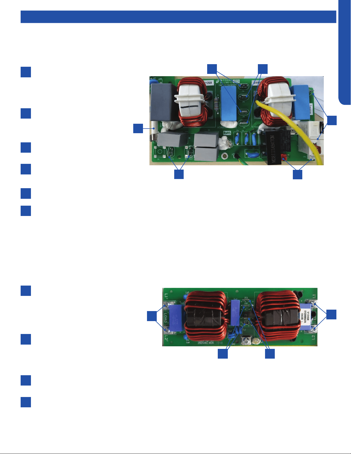
A replaceable, 30A, 250V rated
ceramic fuse protects the outdoor
unit electronics. The fuse will open if
a power surge or internal short in the
outdoor unit has occurred.
The PFB receives line voltage at
terminals P1 and P2 from the outdoor
unit high voltage terminal block 1/N
and 2/L.
The voltage that powers the indoor
units connects to terminals P3 and P4.
The PCB receives power to operate
via connections at terminals P5 and
P6.
The IPM receives power via connections at terminals P7 and terminal 3.
There is a communication plug labeled CN-1 on the PFB. This plug connects from the PFB to the PCB. If this cable is
disconnected or loose, the system will generate a Code 6 module low or high voltage error. This error will not be displayed
in memory on the indoor unit wired controller. CN-1 and CN-2 connect to the PCB at terminals CN-6 and CN-34. CN-6 is
the low stand-by power connection. When power has been turned o at the controller for 5 minutes, CN-6 will remove the
12 VDC signal and open relay RL-1 on the PFB. This saves energy by shutting o power to the IPM. The capacitors must
have current ow before the compressor can start. CN-34 is the capacitor charging circuit. When the capacitors are fully
charged, the circuit opens to stop the charging process via the RL-2 relay. The voltage between the two pins of CN-1 and
the two pins of CN-2 is 12 VDC.
2
2
6
4
4
3
3
5
1
1
The purpose of the PFB is to lter out potential electrical noise before it reaches the outdoor unit electronic circuits. All voltage
to operate the outdoor unit circuits must pass through the PFB.
1
2
6
4
5
3
Power Filter Board (PFB)
2U & 3U
4U
L1 & L2 is the input port of Filter Board,
they will provide 208/230Vac, 60Hz power
to the whole unit group(outdoor unit
&indoor unit ),as is shown in the wiring
diagram, these two terminal connect to the
OUD main power supply terminal block.
P1 & P3 is the one of the rst stage ltered
output of the Filter Board, they will provide
208/230Vac, 60Hz power to all the indoor
units which connect to the outdoor unit. As
is shown in the wiring diagram, these two terminals connect to one of the IDU & OUD connection terminal block.
P2 & P4 is the other one of the rst stage ltered output of the Filter Board, they will provide 208/230Vac, 60Hz power to
the main control board. As is shown in the wiring diagram, these two terminals connect to the ODU main control board CN2
L1 & L2 is the 2nd stage ltered output of the Filter Board, they will provide 208/230Vac, 60Hz power to the compressor
drive module (inverter board). As is shown in the wiring diagram, these two terminals compressor drive module’s power
input L1 & L2.
1
23
4
OUTDOOR TECHNICAL OVERVIEW
B-6
ENGLISH
Operations
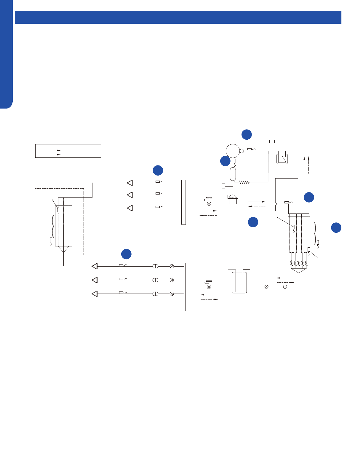
On a call for cooling, the indoor unit will send the room temperature and set-point requirement to the outdoor unit PCB via the
data signal wire path. The data travels from the indoor unit to the outdoor unit via the wire located on terminal 3/C. The indoor
louvers will open and the indoor fan motor will start.
The outdoor unit will energize the EEVs that are controlling refrigerant ow to the calling indoor units. The position of the EEVs
will be set to an initial position based upon the outdoor air temperature.
The 4-way valve is de-energized. After a 3-minute time delay, the outdoor fan motor will be energized. Shortly after the outdoor
fan motor turns on, the compressor will start in low frequency. The operating frequency of the compressor will be displayed on
the Service Monitor Board .
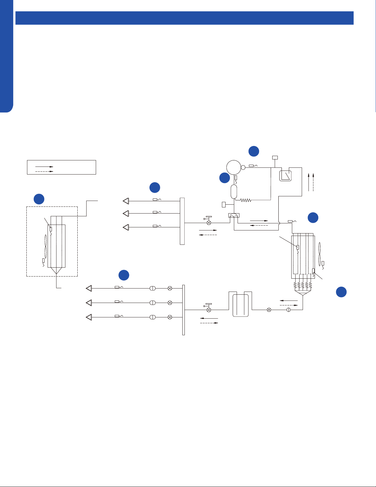
The refrigerant in the system will begin to ow, and the compressor will discharge hot gas into the oil separator. Oil will be
trapped in the separator and returned to the suction inlet of the compressor via the capillary tube assembly low pressure path.
Comp-
ressor
D
ischarge temp.
●
sensor
Oil
separator
Capillary tube
Ø2.7*Ø1.0*1400
High pressure
switch
4-way valve
Pipe sensor
Toci
Suction temp.
sensor Ts
Low pressure
switch
Accumulator
Gas service valve
Outdoor
heat
exchanger
temp.
sensor
FAN-OUT
Outdoor
ambient
temperature
sensor Ta
Defrost
sensor Td
Distributor
Strainer
EEV O
Receiver
Liquid service valve
5/8
3/8
Unit A liquid pipe temp. sensor Tc2
Strainer
EEV A
Indoor unit A
Unit B liquid pipe temp. sensorTc2
Strainer
EEV B
Indoor unit B
Unit C liquid pipe temp. sensor Tc2
Strainer
EEV C
Indoor unit C
Unit A gas pipe temp. sensor Tc1
Unit
B gas pipe temp.
sensor Tc1
Unit C gas pipe temp. sensor Tc1
Indoor unit A
Indoor unit B
Indoor unit C
4-way valve coil:
OFF
ON
Refrigerant flow in cooling
Refrigerant flow in heating
FAN-IN
Indoor
ambient
temperature
sensor
Indoor
heat
exchanger
temp.
sensor
1
2
3
4
7
6
5
Te
Cooling Mode Sequence of Operation

OUTDOOR TECHNICAL OVERVIEW
B-7
ENGLISH
Operations
1
Temperature Sensor Td
The temperature of the compressor discharge hot gas will be
monitored by the Discharge Temperature Sensor. If the sensor
reads too hot or cool, the frequency/status of the operation
will be adjusted accordingly.
The hot gas will leave the oil separator and enter the 4-way
valve, which directs the hot gas to the outdoor coil. The
refrigerant will condense in the outdoor coil and be subcooled.
The refrigerant is now in a liquid state.
2
Temperature Sensor Toci
The temperature of the hot gas leaving the 4-way valve will be
monitored by the Toci Temperature Sensor. This temperature
should be near the temperature of the compressor discharge
gas temperature. If it is not, there is a problem with the 4-way
valve. The PCB will detect the temperature dierence and
generate an Error Code.
3
Temperature Sensor Tc
This sensor monitors the temperature of the outdoor
coil during condensing operation. If abnormal condensing
temperature is detected, the outdoor fan motor speed or
compressor frequency may be adjusted.
4
Temperature Sensor Ta
The outdoor air temperature will be monitored by the PCB.
If the outdoor air temperature rises or falls, the speed of the
outdoor fan may be changed.
5
Temperature Sensor Tc2
The Liquid Pipe Sensor will monitor the temperature of the
refrigerant leaving the EEV.
The low pressure low temperature refrigerant will enter the
mixed phase liquid line and travel to the indoor unit. Heat from
the indoor air passing across the evaporator coil will transfer
to the cold refrigerant, sending cool air into the space and
changing the liquid refrigerant into a cool vapor.
The cold vapor will travel down the vapor line and return to the
outdoor unit via a path through the gas stop valve.
6
Temperature Sensor Tc1
The Gas Pipe Sensor will monitor the temperature of the
gas pipe to calculate the dierence between Liquid Pipe
Temperature and Gas Pipe Temperature. If a change in
EEV port opening size is needed, the EEV will make a small
adjustment.
The vaporized refrigerant enters the 4-way valve and travels
to the vapor line accumulator. The accumulator will trap any
liquid refrigerant if present to prevent it from entering the
compressor.
The vapor will exit the accumulator and enter the compressor.
This cycle will repeat until the demand for cooling ends.
7
Temperature Sensor Ts
The temperature of the suction gas entering the compressor
is monitored by the Suction Temperature Sensor. Before
stopping operation, the EEV may open to feed more
refrigerant or close to warm up the line.
The demand becomes less as the indoor temperature drops
toward the desired temperature, so the compressor will
reduce speed. When the set temperature is reached, the
compressor and outdoor fan will shut o. The circulating fan
of each indoor unit continues to run.
OUTDOOR TECHNICAL OVERVIEW
B-8
ENGLISH
Operations
Comp-
ressor
D
ischarge temp.
●
sensor
Oil
separator
Capillary tube
Ø2.7*Ø1.0*1400
High pressure
switch
4-way valve
Pipe sensor
Toci
Suction temp.
sensor Ts
Low pressure
switch
Accumulator
Gas service valve
Outdoor
heat
exchanger
temp.
sensor
FAN-OUT
Outdoor
ambient
temperature
sensor Ta
Defrost
sensor Td
Distributor
Strainer
EEV O
Receiver
Liquid service valve
5/8
3/8
Unit A liquid pipe temp. sensor Tc2
Strainer
EEV A
Indoor unit A
Unit B liquid pipe temp. sensorTc2
Strainer
EEV B
Indoor unit B
Unit C liquid pipe temp. sensor Tc2
Strainer
EEV C
Indoor unit C
Unit A gas pipe temp. sensor Tc1
Unit
B gas pipe temp.
sensor Tc1
Unit C gas pipe temp. sensor Tc1
Indoor unit A
Indoor unit B
Indoor unit C
4-way valve coil:
OFF
ON
Refrigerant flow in cooling
Refrigerant flow in heating
FAN-IN
Indoor
ambient
temperature
sensor
Indoor
heat
exchanger
temp.
sensor
On a call for heating, the indoor unit will send the room temperature and set-point requirement to the outdoor unit PCB via the
data signal wire path. The data travels from the indoor unit to the outdoor unit via the wire located on terminal 3/C. The indoor
unit louvers will open. The fan will not start until the coil has warmed suciently to avoid cold drafts.
EEVs serving indoor circuits will step to the standard opening. The outdoor EEV opens to a position based upon the outdoor air
temperature.
The 4-way valve will energize and the outdoor fan will start. The compressor starts at a slow speed and will increase based upon
demand. The indoor fan starts after the indoor coil is warm enough to avoid circulating cool air.
With the compressor operating, refrigerant will begin to ow throughout the refrigeration circuit.
The operating frequency of the compressor will be displayed on the Service Monitor Board.
When the compressor starts, hot gas will ow into the oil separator. Oil will be trapped in the separator and returned to the
suction inlet of the compressor via the capillary tube assembly low pressure path.
1
2
3
4
5
6
2
Te
Heating Mode Sequence of Operation

OUTDOOR TECHNICAL OVERVIEW
B-9
ENGLISH
Operations
1
Temperature Sensor Td
The temperature of the compressor discharge hot gas will be
monitored by the Discharge Temperature Sensor. If the sensor
reads too hot or cool, the frequency/status of the operation
will be adjusted as needed.
The hot gas will leave the oil separator and enter the 4-way
valve. The 4-way valve will direct the hot gas to ALL of the
indoor coils.
Note: Any indoor unit that is in heating mode will have it’s
louver open and indoor fan running. Non-calling indoor units
will receive hot gas but their fans will remain on very low speed
with the louver open. When demand for heat increases, the
indoor fan will speed up to meet the increased demand.
2
Temp. Sensor Tc1 & Indoor Heat Exchanger Temp. Sensor
The temperature of Tc1 should now be hot. This will indicate
the 4-way valve is directing hot gas to the indoor coils. If it
is not, there is a problem with the 4-way valve. The PCB will
detect the temperature dierence and generate an Error
Code.
The indoor heat exchanger temperature sensor will monitor
the temperature of the indoor coil to ensure it is hot enough to
prevent blowing cold air. Once adequately warm temperature
is sensed at the indoor coil, the PCB will increase the fan speed
if needed to meet the demand.
The hot gas entering the indoor coil will condense into a
saturated mix and then be subcooled. The refrigerant will
return to the outdoor unit via the liquid line.
3
Temperature Sensor Tc2
This sensor monitors the temperature of the refrigerant liquid
returning from the indoor coil. The indoor EEV opening angle
is xed.
The liquid will enter the Liquid Line Strainer and will pass
through the OPEN EEV.
The refrigerant liquid now enters a receiver where excess
refrigerant will store.
After the liquid leaves the Liquid Receiver, it will enter the
restriction of the OUTDOOR UNIT’s EEV, which changes the
liquid refrigerant to a lower pressure and temperature as it
enters the outdoor coil.
As the outdoor coil absorbs heat from the surrounding air, the
very cold liquid refrigerant is changed to a cool vapor. This
vapor travels through the 4-way valve to the accumulator.
4
Temperature Sensor Te
The outdoor coil temperature will be sensed by the Defrost
Sensor. The sensor will use this temperature to to adjust EEV
open angle and to calculate when a defrost cycle is necessary.
5
Temperature Sensor Toci
This temperature sensor is now sensing the suction line
temperature of the refrigerant vapor leaving the outdoor coil.
This temperature is used to adjust the EEV open angle.
The vapor refrigerant will then enter the 4-way valve and
be directed to the compressor suction accumulator. The
accumulator will prevent any remaining liquid refrigerant from
entering the compressor.
The vapor will exit the accumulator and enter the compressor.
This cycle repeats until the demand for heating ends.
6
Temperature Sensor Ts
The temperature of the suction gas entering the compressor
is monitored by the Suction Temperature Sensor.
As the demand becomes less while the indoor temperature
rises toward the desired temperature, the compressor will
reduce speed. When the set temperature is reached, the
compressor and outdoor fan will shut o. The circulating fan
of each indoor unit continues to run.
OUTDOOR TECHNICAL OVERVIEW
B-10
ENGLISH
Operations
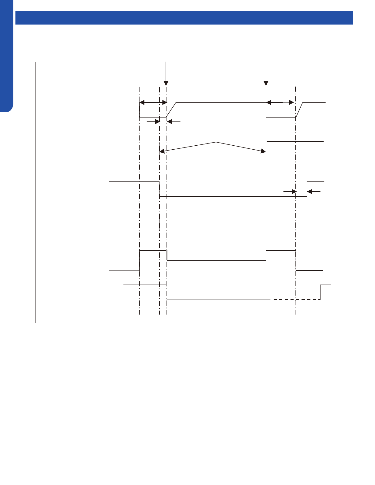
Beginning end
Fixed frequency Indicated FQY 60s Defrosting FQY 80 Hz(E) 60s Soft startup
Compressor
0HZ 0HZ
5s
Outdoor motor ON Send defrosting signal to indoor Auto
OFF
4-way valve ON
OFF 15s
450-pulse 450-pulse
350-pulse(E)
All EEVs Auto open angle Auto open angle
All indoor motors ON
OFF Anti- cold air fun ction
Multi:
Defrost Cycle Sequence of Operation
OUTDOOR TECHNICAL OVERVIEW
B-11
ENGLISH
Operations
Electronic Expansion Valve (EEV) Control
Electronic characteristics
Max. open angle 480 pulses
Driving speed PPS
Open angle limitation of EEV
Unit stop Max. open angle Thermostat OFF Min. open angle
Cool/ dry 5 pulses 480 pulses 5 pulses 80 pulses
Heat 5 pulses 480 pulses 50 pulses 80 pulses
The EEV routinely opens and closes to maintain the compressor discharge temperature within an acceptable range.
c
ompressor ON
OFF
4
-way valve ON
OFF
50S
2 minutes and 55s
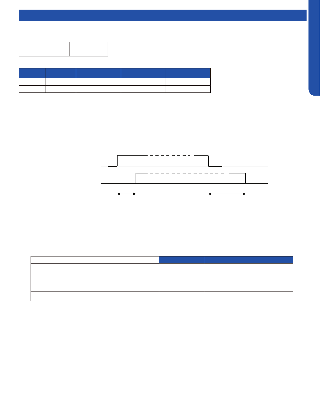
4-Way Valve Heating Control
When the compressor starts in the heating mode, there is a 1-minute delay before power is applied to the 4-way valve to switch
the ow of hot refrigerant to the indoor coil. When the call for heat is satised and the compressor shuts o, a 3-minute delay will
occur before the 4-way valve is powered down and switches back to the at-rest (cooling) position.
If the 4-way valve does not switch into the heating mode, after 15 minutes of compressor run time and the indoor coil
temperature is below 41°F/5°C, the compressor will stop and the unit will display a 17-ash error code on the outdoor PCB.
Compressor Sump Heater
The sump (crankcase) heater keeps refrigerant at a higher temperature than the coldest part of the system. This prevents
refrigerant from mixing with the compressor oil and also dries condensed refrigerant inside the sump. The sump heater will be
energized when the ambient temperature is below 81°F/27°C and will be o when the ambient is 90°F/32°C.
Heater OFF Heater ON*min
Ta>50
O
F(10
O
C) OR Td>=68
O
F(20
O
C) 0 0
41
O
F(5
O
C<Ta ≤50
O
F(10
O
C)and Td<68
O
F(20
O
C) 50%*60min 50%*60min
32
O
F(0
O
C)<Ta ≤41
O
F(5
O
C)and Td<68
O
F(20
O
C) 33%*60min 66%*60min
32
O
F(0
O
C)>=Ta andTd<68
O
F(20
O
C) 0 100%*60min
OUTDOOR TECHNICAL OVERVIEW
B-12
ENGLISH
Operations
Base Pan Heater Control Logic
When the compressor starts in the heating mode, the
following conditions will apply:
Troubleshooting the Base Pan Heater Error:
Step 1:
Check the pan heater for an open circuit or shirt circuit.
Unplug the connector from main control PCB. Test the
resistance between the two pins of the pan heater connector.
It should be 0.28-0.379KΩ. If out of range, change the pan
heater. If normal go step 2.
Step 2:
Check the main control board pan heater output port . Unplug
the connector from main control PCB. Run the ODU with
manually forced heating (Set the display board SW 1-1 as
ON). Test the voltage between the two heater output pins, it
should be 208-230Vac.
Defrost Control
In the heating mode and along with the ambient sensor, the
defrost sensor monitors the temperature of the outdoor
coil to determine if defrost is needed. If the compressor has
been running for 10 minutes continuously and for 45 minutes
overall, the dierence between the ambient sensor (Ta) and
the defrost sensor (Te) will be checked. The system will
initiate the defrost cycle if the following conditions can be met
for 5 continuous minutes:
Te ≤ C x Ta-A
Te: Defrost temperature sensor
Ta: Ambient temperature
C: 0.80 if Ta < 32°F/0°C, 0.60 if Ta ≥ 32°F/0°C
A: 8, moderate climate (factory setting). 6, severe climate
(alternate setting)
End Defrosting:
If the defrost sensor (Te) detects the temperature of the
outdoor coil is above 44°F(7°C) for 60 seconds or is above
54°F(12°C) for 30 seconds, the defrost cycle will terminate. If
these temperatures cannot be reached, the defrost cycle will
automatically terminate in 10 minutes.
Timed Defrost Option:
• When the outdoor ambient temperature sensor detects Ta
is less than 32°F(0°C)
• In heating mode, compressor runs continuously for 60
minutes or for 240 minutes in all
• When the above conditions are met, the system will defrost.
Defrosting frequency is 68 HZ, with a defrosting time of 8
minutes.
Outdoor Temperature Pan Heater
>37
o
F(3
o
C) OFF
28
o
F(-2
o
C) to 34
o
F(1
o
C) OFF 20min. ON 10min.
10
o
F(-12
o
C) to 25
o
F(-4
o
C) OFF 15min. ON 15min.
<10
o
F(-12
o
C) ON
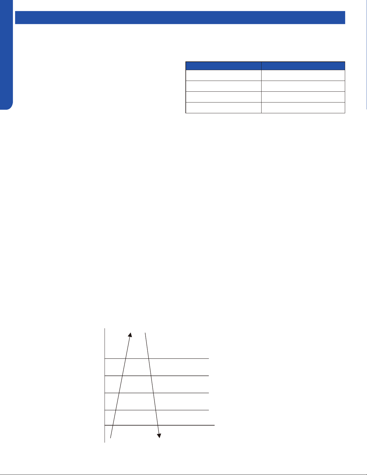
Discharge Sensor Protection
If the discharge temperature is higher than normal, the compressor will slow down to lower the temperature.
℃
℃
℃
℃
℃
℃
Multi:
Discharging temp. Td
Reduce FQY rapidly 1HZ/S
Reduce FQY slowly 1HZ/10S
Remain FQY
Increase FQY slowly 1HZ/10S
Remain FQY
If the discharge temperature sensor reaches 243F for 10
seconds, the compressor will shut off. After the 3-minute
time delay, the compressor will restart. If this occurs
three times in a 60-minute period, the compressor will
lock out. Until the cause of the high temperature is
discovered, the compressor will not restart until the
power is interrupted then restored.
203℉( 95℃)
207℉( 97℃)
225℉( 107℃)
234℉( 112℃)
243℉( 117℃)
OUTDOOR TECHNICAL OVERVIEW
B-13
ENGLISH
Operations
High Current Protection
The below table is the outdoor unit protection current and compressor current.
If the temperature reaches 150
O
F(66
O
C) three times in one hour, the
system will lock out. Reset by turning power o and back on.
Reduce FQY rapidly 2Hz/S
Reduce FQY rapidly 1Hz/S
Reduce FQY rapidly 1Hz/10S
Remain FQY
Reduce FQY slowly 1Hz/S
100%*I
98%*I
96%*I
96%*I
90%*I
88%*I
Remain FQY
Model Maximum current (I) Compressor current (CT)
2U20EH2VHA 12.5A 10A
3U24EH2VHA 13.5 14A
4U36EH2VHA
??? ???
High Pressure Protection in Cooling
If there is an abnormal stop 3 times in 1 hour, the unit
will turn o. Turn o and restore power to clear error.
Reduce FQY rapidly 2Hz/S
Reduce FQY slowly 1Hz/S
Remain FQY
Raise FQY slowly 1Hz/10S
131
O
F(55
O
C)
Tc--cooling
138
O
F(59
O
C)
144
O
F(62
O
C)
147
O
F(64
O
C)
150
O
F(66
O
C)
Remain FQY
If the temperature reaches 158
O
F(70
O
C) three times in one hour,
the system will lock out. Reset by turning power o and back on.
Reduce FQY rapidly 2Hz/S
Reduce FQY slowly 1Hz/S
Remain FQY
Raise FQY slowly 1Hz/10S
129
O
F(54
O
C)
Tc--heating
135
O
F(57
O
C)
138
O
F(59
O
C)
145
O
F(63
O
C)
158
O
F(70
O
C)
Remain FQY
High Pressure Protection In Heating

OUTDOOR TECHNICAL OVERVIEW
B-14
ENGLISH
Operations
Low Pressure Protection
With the compressor running, if the low pressure switch opens for 1 minute, the compressor will stop.
If this condition occurs 3 times in an hour, the compressor will lock out and a low pressure error code will be displayed at the
indoor unit.
If the compressor is not running and the switch opens for 30 seconds, a low pressure error code will be displayed.
The low pressure switch does not stop compressor operation or signal an error code during the following conditions:
• The rst 8 minutes of run time when the compressor starts a new cycle
• During defrost
• When the ambient temperature is below 32°F/0°C
• Following the termination of an oil return cycle
When any of the above 4 conditions are present, low pressure protection is provided by the coil temperature sensors in both
heating (Te) and cooling (Tc2) modes.
Operate normally
Min. running FQY 20Hz
LP OFF & FQY 20Hz
LP ON & FQY 20Hz
Raise FQY slowly 1Hz/10S
-49
O
F(-45
O
C)
Tc 2
-40
O
F(-40
O
C)
-31
O
F(-35
O
C)
-22
O
F(-30
O
C)
-13
O
F(-25
O
C)
Low Pressure Protection in Heating Mode:
Operate normally
Min. running FQY 20Hz
LP OFF & FQY 20Hz
LP ON & FQY 20Hz
Raise FQY slowly 1Hz/10S
-49
O
F(-45
O
C)
Te
-40
O
F(-40
O
C)
-31
O
F(-35
O
C)
-22
O
F(-30
O
C)
-58
O
F(-45
O
C)
Low Pressure Protection in Cooling Mode:

OUTDOOR TECHNICAL OVERVIEW
B-15
ENGLISH
Operations
Send oil return signal oil return begins oil return over
60s ref. eliminated 30s
Oil return frequency auto frequency
Low frequency
Inverter compressor auto frequency
350 pulses(E)
running indoor EEV auto angle auto angle
120 pulses(E)
80(E)
stopped indoor EEV OFF angle 5(E) OFF angle 5(E)
Outdoor motor AUTO AUTO (TC or ambient temp. control) AUTO
running indoor motor AUTO AUTO (set fan speed) AUTO
stopped indoor motor STOP STOP STOP
4-way valve OFF OFF OFF
Oil Return in Cooling Mode:
Oil Return Cycle
When the compressor is operating at low load
conditions, or the operating frequency has
been below 70Hz continuously for 4 hours,
the system will enter the oil return cycle. This
ensures that oil which may be trapped within
the system at low loads will return to the
compressor crankcase.
If a 4-hour low speed run time has occurred,
the oil return procedure initiates by
automatically ramping up the compressor
speed to at least 85Hz for a pre-set time, up
to a 9-minute maximum. The higher speed
will wick hiding oil into the now faster-moving
refrigerant and deposit it in the compressor
crankcase. To avoid occupant discomfort
when the oil return cycle is active, the indoor
fan shuts o.
Should an error code result in a system
shutdown, the oil return cycle timing will
resume when the error code has been cleared.
& ‐ > ℉(℃)
‐ > ℉(℃)
<
Oil Return Exit Conditions, Heating:
‐ <
& ‐ <
Send oil return signal oil return begins oil return over
Inverter compressor indicated FQCY 60s oil return FQCY 60s soft startup
0HZ 0HZ
5s
Outdoor motor AUTO AUTO
AUTO (TC control)
4-way valve ON
OFF 15s
450 pulses 450 pulses
350 pulses
All expansion valves auto angle auto angle
Indoor fan motor ON
OFF Cold air proving mode
℉(℃)
℉(℃)
℉(℃)
& ‐ > ℉(℃)
‐ > ℉(℃)
<
Oil Return Exit Conditions, Heating:
Max. 9 minutes (E)
OR OR Td Tc‐ < for 30s continuously(5 minutes later, begin
to count)
& Ts Tc2AVE‐ < for 30s continuously(5 minutes later,
begin to count)
Running for min. 5 minutes
℉(℃)
68℉(20 ℃)
59℉(15 ℃)
Oil Return Exit Conditions, Cooling:
1 minute later after oil return is over
& Td Tc‐ >86℉(30 ℃)
OR OR Ts Tc2AVE‐ >86℉(30 ℃)
Tc2AVE<
Max. 10 minutes
‐ <
& ‐ <
-31℉(-35 ℃)
℉(℃)
℉(℃)
Oil Return in Heating Mode
Oil Return in Cooling Mode
OUTDOOR TECHNICAL OVERVIEW
B-16
ENGLISH
Testing
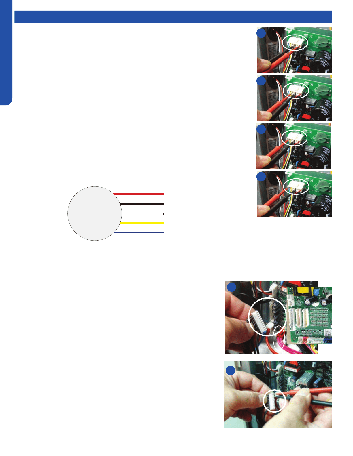
Outdoor Fan Motor
Check that the wiring and plug connections are in good condition.
If the outdoor unit fan motor does not run, or the Service Monitor Board indicates an error
code of 09, check the following voltages at the motor connector on the outdoor unit PCB. Set
the meter to read DC volts with a minimum voltage range of 350 volts. All voltage values are
approximate. Initiate forced cooling.
1. DC voltage between the Red and Black wire connnections should read 310 ~ 334 VDC. This
is the main voltage for powering the fan motor.
2. DC voltage between the White and Black wire connnections should read 15VDC. This is the
voltage for powering the electronic circuit of the fan motor.
3. DC voltage between the Yellow and Black wire connnections should read 4VDC. The voltage
will read 0VDC when the fan is not being called to operate. This is the control voltage for
regulating the speed of the fan motor.
4. DC voltage between the Blue and Black wire connnections should read 8VDC. The voltage
will read 14VDC when the fan is not being called to operate. (This is the feedback voltage to
the PCB for determining the speed of the fan motor)
If the outdoor fan initially runs, increases speed then stops, and the Service Monitor Board
indicates an error code of 09, the feedback circuit is not functioning. Check that the wiring and
plug connections are in good condition.
Outdoor Fan 310VDC
Pins 1 - 3
Outdoor Fan 15VDC
Pins 3 - 4
Outdoor Fan Control
Pins 3 - 5
Outdoor Fan Feedback
Pins 3 - 6
Temperature Sensor
The temperature sensors are negative coecient thermistors, in which resistance
decreases as temperature rises. Should the sensors fail, the PCB will generate an
appropriate error code.
To check the calibration of the sensors:
1. Shut o power to the outdoor unit.
2. Disconnect the sensor at the circuit board plug.
3. Measure the temperature of the air surrounding the sensor.
4. Measure the electrical resistance of the sensor using needle probes. Do not
force standard probes into the sensor plug.
5. Compare the measured resistance of the sensor against the resistance/
temperature specications (See chart in reference section)
6. If the sensor resistance is outside of the specication tolerances shown on the
resistance/temperature table, replace the sensor.
1
2
3
4
2
4
DC Motor
+310 VDC
DC Ground
+15 VDC
Signal
Feedback
Red
Black
White
Yellow
Blue
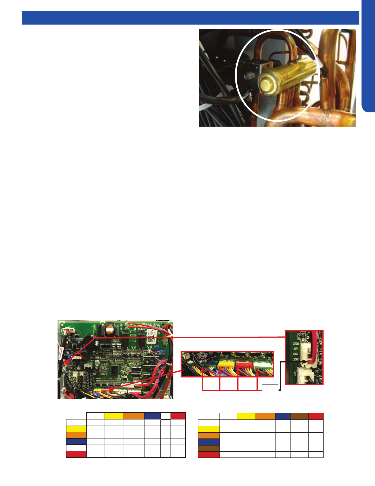
OUTDOOR TECHNICAL OVERVIEW
B-17
ENGLISH
Testing
4-Way Valve
The 4-way valve will control the direction of hot gas discharge via
an internal slide assembly. The valve has a line voltage solenoid
that is energized in heat mode. The solenoid will direct the internal
slide to send the hot gas to the indoor coil. During cooling mode
de-energized operation, the internal slide will direct compressor
hot gas to the outdoor coil.
4-way valves may have a failure of the electrical solenoid that
prevents the valve from shifting, or they may become stuck due to
debris lodging inside the valve body. If the valve fails to direct the
hot gas in the proper direction, temperature sensors within the
outdoor unit will detect the problem and generate an error code.
If the valve fails to shift the hot gas to the proper coil, or it only
partially shifts, perform the following:
1. Check for correct refrigerant charge, and that all other operating parameters have been met.
2. In the heating mode, the solenoid will shift after a short time delay. Check for line voltage to the solenoid coil.
3. If the valve has voltage but fails to shift the hot gas to the indoor coil, shut the system down and unplug the 4-way valve from
the PCB plug.
4. Use an ohmmeter to check continuity through the solenoid coil. The coil resistance should be 2.1k Ohms. If a winding shows
open or shorted, the solenoid coil will have to be replaced.
5. If the coil resistance is within the tolerance, use a magnet along the valve body to determine the location of the piston. If one
end of the piston is against the end of the valve body, it is stuck and the valve must be replaced.
6. Partial shifting of the valve can be detected by measuring the temperature of the suction gas where it enters the reversing
valve and then comparing that temperature to the temperature of the suction gas exiting the 4-way valve. There should be
no more than a 13°F dierence. Excessive temperature rise through the suction gas path is an indication of a stuck piston. If
the piston will not become free by switching from heating to cooling several times, a slight tapping on the valve body, or by
using a powerful magnet, the valve will require replacement.
12VDC
EEV Terminals
Electronic Expansion Valve (EEV)
EEV (6-pin, 6 wire)
White Yellow Orange
Blue Brown Red
White - OL 92 Ω OL 46 Ω OL
Yellow - - OL 92 Ω OL 46 Ω
Orange - - - OL 46 Ω OL
Blue - - - - OL 46 Ω
Brown - - - - - OL
Red - - - - - -
EEV (6-pin, 5 wire)
White Yellow Orange
Blue X Red
White - 92 Ω 92 Ω 92 Ω - 46 Ω
Yellow - - 92 Ω 92 Ω - 46 Ω
Orange - - - 92 Ω - 46 Ω
Blue - - - - - 46 Ω
X - - - - - -
Red - - - - - -
1. Check to see if the Electronic expansion valve (EEV) connector is correctly and rmly inserted in the PCB.
2. Turn the power o and back on again,
3. Check to see whether the EEV have a reposition sound. This sound will start after approx 2 min. If the EEV doesn’t have noise,
please disconnect the connector and check the resistance (refer to resistance tables below).
4. If the resistance is OK, The PCB may be at fault.
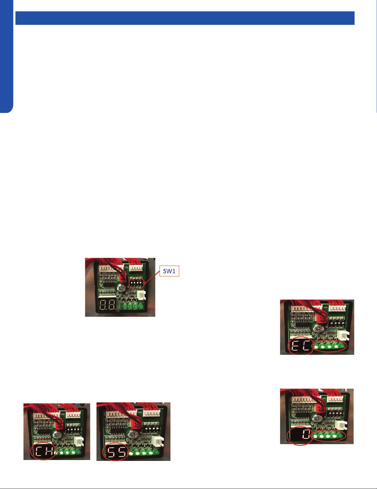
OUTDOOR TECHNICAL OVERVIEW
B-18
ENGLISH
Topic TitleTesting
Variable Speed Compressor
1. Begin by turning o power at the equipment disconnect switch. Adequate time must be given for capacitors on the circuit
board to discharge. Wait a minimum of 12 minutes before handling the circuitry.
2. Locate the Inverter control module (IPM). The IPM is connected to the main circuit board by a wire harnesses, and has the
compressor connections mounted on it.
3. Set your test meter to AC volts and test for voltage at the three compressor connections. Voltage should be zero before
proceeding.
4. Remove the three compressor connections making note of the terminal letter and the wire colors.
5. Set your ohm meter to the lowest resistance setting that is available. Test all three connections terminals using the following
sequence:
• U terminal to V terminal
• U terminal to W terminal
• V terminal to W terminal
All three resistance values should match the specication table below. Compressor windings are deemed bad if they are
greater than 7% out of specication. Readings taken at the wire IPM module that are outside of factory tolerances require
steps 6 through 9.
6. Remove the compressor blanket and set it aside. Remove the terminal block cover to expose the connections at the
compressor terminals. Inspect for any visual damage. Remove all three wires from the terminals making note of the wire color
and the terminal identier.
7. Repeat process outlined in step 5. Repair or replace the wires if the compressor windings check properly.
8. Check each terminal to ground (suction line connection at compressor) to check for grounded windings if the resistance
values are not correct.
9. Replace the compressor if the winding measurements are greater than 7% out of specication.
Wiring Error Check
1. Disconnect power to
the outdoor unit.
2. Set Dip Switches
SW1-1, SW1-2,
SW1-3 & SW1-4 to
the ON position.
These dip switches
are located on the
Service Monitor
Board.
3. Turn ON power to the outdoor unit.
4. All indoor fans will be set to HIGH fan speed.
5. EEV for Circuit A will open. All other EEV’s will close.
6. After a 3 minute delay, the Compressor will start and ramp
up to 55HZ.
7. The digital display with alternately display “CH” and
“Compressor Frequency (HZ)” at 5 second intervals
8. The system will circulate refrigerant through Circuit A for
approximatley 10 minutes.
9. Afterwards, Circuit A’s EEV will close and Circuit B’s EVV
will open.
10. This process will be repeated for each indoor unit that is
connected.
11. Once all indoor units have
been checked, the digital
display will display either
“EC” or “0”. “EC” indicates
a communication error
between the outdoor and
indoor unit. The LED(s) will
be ashing, indicating which
circuit has the fault
12. Once the wiring is corrected, re-run this test to conrm
everything is functional.
13. “0” indicates that all wiring is
correct.
14. If all wiring is correct, the
LED’s remain solid lit.
15. Once the test is complete,
make sure to change the dip
switches back to the OFF
position, and set each indoor
unit to preferred set points.
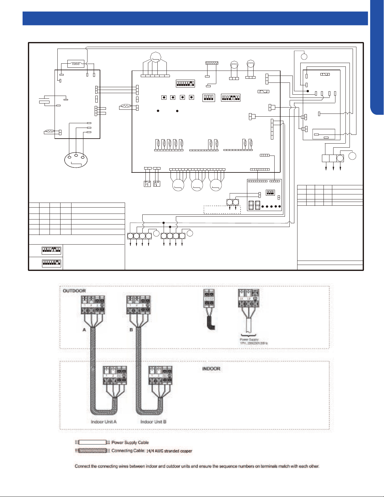
OUTDOOR TECHNICAL OVERVIEW
B-19
ENGLISH
Topic TitleWiring Diagrams
2U20EH2VHA
GR
1 2 3 4 5 678
SW3
SW4
SW2
SW1
CN12
LP
HP
CN13
CN9
GND
CN11
CON8
CN8
CN5
W
TO Module
M
LED_G
LED_R
CN6
4-WAY VALVE
DC-FAN
MOTOR
M
250VAC T5A
FUSE
CON9
FG
Vsp
Vcc
CN25
CN16
ACN
ACL
ON
4321
ON
W
W
Vdc
L1 L2
Power
CN2
CN23
CN21
SW6
SW5
W
W
B
B
COMPRESSOR
Y
M
CN17
R
M
CN15
CRANKCASE HEATER
Definition of SW6
1
2
3
4
OFF
OFF
OFF
OFF
OFF
OFF OFFON
ON
ON
ON ON
Centralized Control
Address=1
Address=2
Address=16
---------------
---- ---- ---- ----
Definition of SW1
SW1-1
SW1-2
SW1-3
SW1-4
Normal Operating(Default)
OFF
OFF
OFF
OFF
ON
OFF
OFF
OFF
OFF
ON
OFF
OFF
OFF
OFF
ON OFF
Force Heating
Force Cooling
Rated Operating
To Indoor
Unit B
2
1
3
OR: Orange B: Black BL: Blue GR:Green R: Red
Y/G: Yellow/Green W: White Y: Yellow BR: Brown
E.E.V:Electro expansion valve
LP/HP:Low /high pressure switch
Toci: Outdoor Condensing inlet Temp. sensor
Tc: Outdoor Condensing Temperature Sensor
Ts: Compressor Suction Temp. Sensor
Ta: Ambient Temp. Sensor
Td: Compressor Discharge Temp. Sensor
Te: Defrosting Temp. Sensor
Tm: Module Temp. Sensor
Tc1(a/b/c/d/e):Condensing Temp. Sensor
for Indoor Units a/b/c/d/e (Gas Pipe)
Tc2(a/b/c/d/e):Condensing Temp. Sensor
for Indoor Units a/b/c/d/e (Liquid Pipe)
R
P2(N)
F30A 250VAC
FUSE
P1(L)
RL1
P7
P6
P5
P4
P3
W
B
ON
4321
CN2
CN3
CN1
CN4
SW1
4321
5
1 2 3 4 5 678
ON
SW7
W
W
B
B
0150530741
To Indoor
Unit A
2
1
3
R
C2
C1
A
B
To central
Controller
OFF
OFF
ON
OFF
Time Defrost Valid
3
4
CN1
R
BR
R
BL
OR
Y
W
R
BL
OR
Y
W
R
BL
OR
Y
W
R
R
W
W
B
W
B
W
W
W
R
W
W
W
BL Y W
B
R
R
B
W
2U20EH2VHA
SW5
1
3
4 5
6
7
8
ON
SW7
1
2
3
4 5
6
7
8
ON
Default setting
of SW5 & SW7
BR
G
G
G
G
G
G
G
Y/G
Y/G
Y/G
Y/G
W
U
R
V
B
W
+
-
BR
BL
Electrolytic
Capacitor
Reactor
U
V
W
ACN
RI
N(-)
P(+)
ACL
RO
CN15
Tm
CN8
B
W
W
GR
B
OR
OR
W
CN11
R
R
W
CN2
R
CN34
R
CN4
GR
BL BL
R
GRAY
OR
OR
Base Pan Heater
Tc
CN14
CN1 CN24
Ts
Ta
Td
Te
BA BA
TC1
TC2
Toci
CN7
W
B
W
CN17
BL
R
2
E.E.V-O
E.E.V-A
E.E.V-B
*
The dashed part is optional.
R
Inverter Power
Module
MAINCONTROLBOARD
POWER
FILTER
BOARD
PMV-RE PMV-A
PMV-B
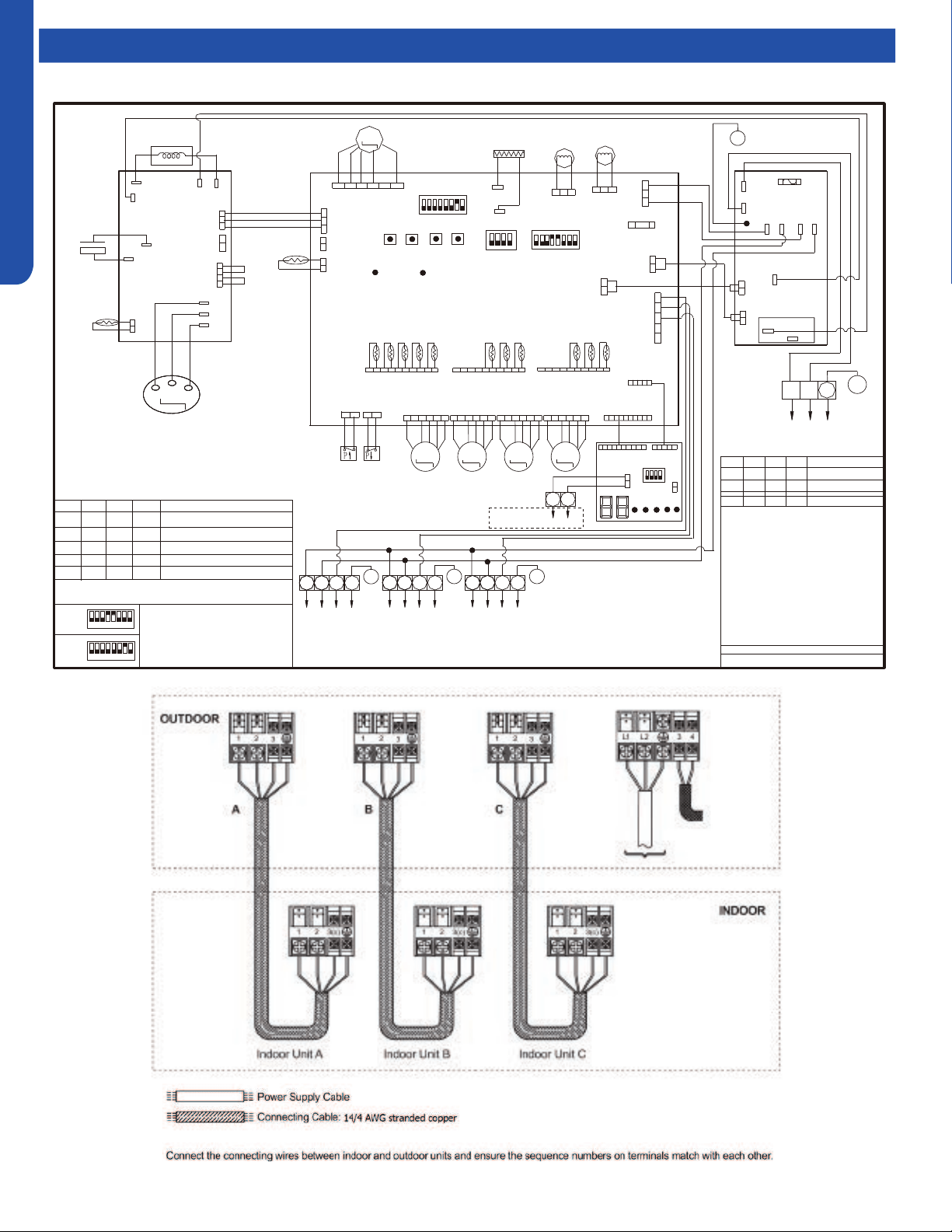
OUTDOOR TECHNICAL OVERVIEW
B-20
ENGLISH
Topic TitleWiring Diagrams
GR
1 2 3 4 5 678
SW3
SW4
SW2
SW1
CN12
LP
HP
CN13
CN9
GND
CN11
CON8
CN8
CN5
W
TO Module
MAINCONTROLBOARD
M
LED_G
LED_R
CN6
4-WAY VALVE
DC-FAN
MOTOR
M
250VAC T5A
FUSE
CON9
FG
Vsp
Vcc
CN25
CN16
ACN
ACL
ON
4321
ON
W
W
Vdc
L1 L2
Power
CN2
CN23
CN21
SW6
SW5
W
W
B
B
R
COMPRESSOR
Y
M
CN17
R
M
CN18
BL
M
CN15
CRANKCASE HEATER
Definition of SW6
1
2
3
4
OFF
OFF
OFF
OFF
OFF
OFF OFFON
ON
ON
ON ON
Centralized Control
Address=1
Address=2
Address=16
---------------
---- ---- ---- ----
Definition of SW1
SW1-1
SW1-2
SW1-3
SW1-4
Normal Operating(Default)
OFF
OFF
OFF
OFF
ON
OFF
OFF
OFF
OFF
ON
OFF
OFF
OFF
OFF
ON OFF
Force Heating
Force Cooling
Rated Operating
To Indoor
Unit C
2
1
3
To Indoor
Unit B
2
1
3
OR: Orange B: Black BL: Blue GR:Green R: Red
Y/G: Yellow/Green W: White Y: Yellow BR: Brown
E.E.V:Electro expansion valve
LP/HP:Low /high pressure switch
Toci: Outdoor Condensing inlet Temp. sensor
Tc: Outdoor Condensing Temperature Sensor
Ts: Compressor Suction Temp. Sensor
Ta: Ambient Temp. Sensor
Td: Compressor Discharge Temp. Sensor
Te: Defrosting Temp. Sensor
Tm: Module Temp. Sensor
Tc1(a/b/c/d/e):Condensing Temp. Sensor
for Indoor Units a/b/c/d/e (Gas Pipe)
Tc2(a/b/c/d/e):Condensing Temp. Sensor
for Indoor Units a/b/c/d/e (Liquid Pipe)
R
R
P2(N)
POWER
FILTER
BOARD
F30A 250VAC
FUSE
P1(L)
RL1
P7
P6
P5
P4
P3
W
B
ON
4321
CN2
CN3
CN1
CN4
SW1
4321
5
1 2 3 4 5 678
ON
SW7
W
W
B
B
0150530715
To Indoor
Unit A
2
1
3
R
C2
C1
A
B
To central
controller
OFF
OFF
ON
OFF
Time Defrost Valid
3
4
CN1
R
BR
R
BL
OR
Y
W
R
BL
OR
Y
W
R
BL
OR
Y
W
R
BL
OR
Y
W
R
R
W
W
B
W
B
W
B
R
W
W
W
R
W
W
W
BL Y W
B
R
R
B
W
3U24EH2VHA
SW5
1
3
4 5
6
7
8
ON
SW7
1
2
3
4 5
6
7
8
ON
Default setting
of SW5 & SW7
BR
G
G
GG
G
G
G
G
G
Y/G
Y/G
Y/G
Y/G
Y/G
W
U
R
V
B
W
+
-
BR
BL
Electrolytic
Capacitor
Reactor
U
V
W
ACN
RI
N(-)
P(+)
ACL
RO
CN15
Tm
CN8
B
W
W
GR
B
OR
OR
W
CN11
R
R
W
CN2
R
CN34
R
CN4
GR
BL
BL
R
GRAY
OR
OR
Base Pan Heater
Tc
CN14
CN1 CN24
Ts
Ta
Td
Te
C
BA
C
BA
TC1
TC2
Toci
CN7
W
B
W
CN17
BL
R
2
PMV-RE
PMV-A
PMV-B
PMV-C
E.E.V-O
E.E.V-A
E.E.V-B
E.E.V-C
*
The dashed part is optional.
Inverter Power
Module
3U24EH2VHA
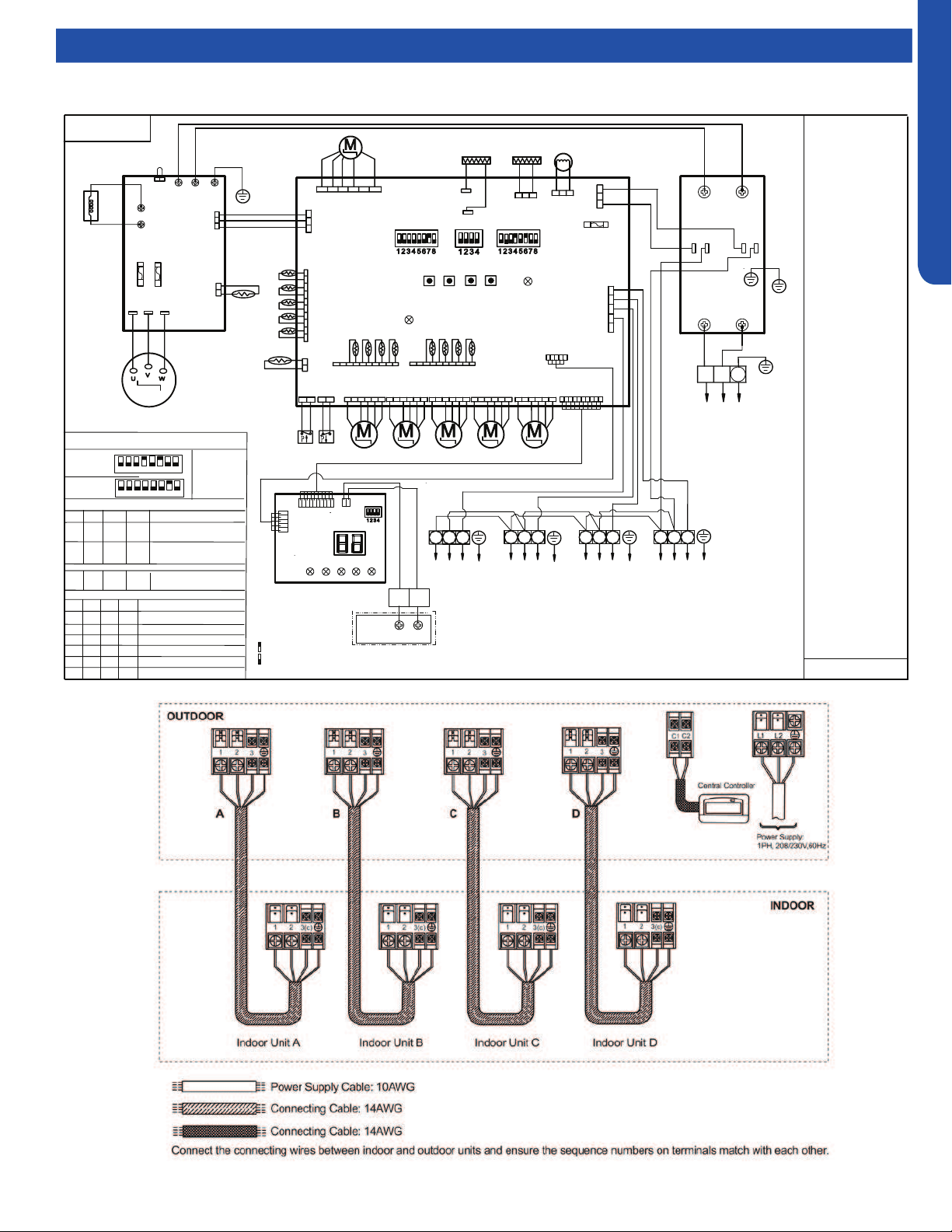
OUTDOOR TECHNICAL OVERVIEW
B-21
ENGLISH
Topic TitleWiring Diagrams
4U36EH2VHA
LP
HP
CN9
GND
CN11
CON8
CN5
MAIN CONTROL BOARD
4-WAY
VALVE
DC FAN
MOTOR
250VAC T5A
FUSE
CON9
FG
Vsp
Vcc
ON ON
Vdc
L1 L2
Power supply
CN2
SW7
COMPRESSOR
CN15
CRANKCASE
HEATER
2
1
3
POWER FILTER
BOARD
P4
P2
P3
P1
ON
W
B
2
1
3
BL Y W
B
R
G
Y/G
Y/G
Reactor
L2
CN6
CN4
BL
BL
R
GRY
OR
OR
BASE PAN
HEATER
CN1 ( TC1)
CN24( TC2)
E.E.V-O
E.E.V-A
E.E.V-B E.E.V-C
DRIVE MODULE
P
1
1
T20A/250VAC
COMM.
T
fin
L1
Tc
CN14
D
CN13
E.E.V-D
CN16 CN17 CN18 CN19
CN8
B
W
R
31
2
To Indoor
Unit A
31
2
CN23
CN21
ON
To Indoor
Unit B
To Indoor
Unit C
To Indoor
Ts
Ta
Td
T
e
C B A
D C B A
LED2
SW6 SW5
U V W
SERVICE
DISPLAY
BOARD
A B
CN3
CN2
CN4
Sensor abbreviation :
Tc: Condensing Temp.
Ts: Compressor Suction
Temp.
Ta: Ambient Temp.
Td: Compressor Discharge
Te: Defrosting Temp.
Tfin: Module Temp.
TC1:Condensing Temp.
for Indoor Units A/B/C/D
Toci: Outdoor
Condensing inlet Temp.
Other abbreviation:
OR: Orange,Y/G:
Yellow/Green,W: White,
Y: Yellow, BR: Brown,
B: Black, BL: Blue,
GR:Green ,GRY:GREY
R: Red E.E.V:Electro
expansion valve,
LP/HP:
Low /high pressure switch
Note:
1.Dashed parts are
optional.
2.Please refer to
service manual to get
details of the DIP
switches .
3.Do not change the
DIP switches setting
without technical
support.
4.The LED1-LED5 in
the service display
board in turn
corresponds to the
communication status
of ndoor unitA,B,C,D.
LED will not lit if
communication
abnormal.
SW1 SW2 SW3 SW4
Start/+
Stop/-
FA
Y/G
R
EARTH
L1 L2
L1’
(Gas Pipe)
TC2:Condensing Temp.
for Indoor Units A/B/C/D
(Liquid Pipe)
Definition of Dispaly board SW1
SW1-1
SW1-2
SW1-3
SW1-4
Normal Operating(default)
OFF
OFF
OFF
OFF
ON
OFF
OFF
OFF
OFF
ON
OFF
OFF
OFF
OFF
ON OFF
Manually forced Heating
Manually forced Cooling
Rated Operating(fixed speed)
OFF
OFF
ON
OFF
Time Defrost Valid
4U36EH2VHA1
SW5
1
2
3
4 5
6
7
8
ON
SW7
1
2
3
4 5
6
7
8
ON
Factory defaultof main control board SW5 & SW7
Unit D
Remote
central
A
B
controller
0150538688
0150538688
LED1
GR
Other detail s about the service information please please refer to technical service mannual.
Centralized control address
SW6-1
SW6-2
SW6-3
SW6-4
OFF
OFF
OFF
OFF
Definition of main control board SW6
Indoor unit address group1
( NO.1-NO.5) (default)
ON
OFF
OFF OFF
Indoor unit address group2
( NO.6-NO.10)
……
ON
ON
ON ON
Indoor unit address group
16( NO.76-NO.80)
R
W
B
B
W
W
5V(V+)
COM
GND
Toci
B
BL
W
CN7
W R R
Y
GR
BL
W
W
W
pin1
W
R
R
R
R
R
R
W
A
B
C
D
ON
ON
ON
ON
IDU&ODU Wiring Error Check
C1
C2
R
W
GR
W
MAIN side pin1-DISPLAY side pin5
pin1
SW1
B
W
B
B
W
W
B
LED5
SMG1
ON
ON
Means switch at ON position
Means switch at OFF position
R
W
B
pin1
pin1
pin1
W
B
W
B
B
ACL(L1)
ACL(L2)
CN12
R
Y
L2’
T20A/250VAC
LED4
LED3
LED2
LED1
FAN
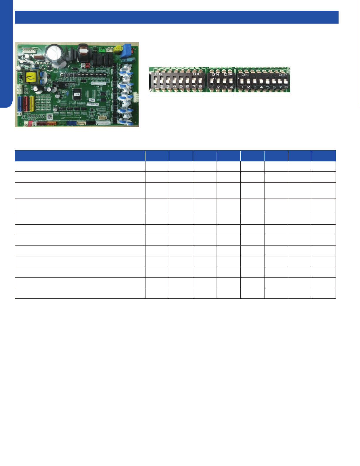
OUTDOOR TECHNICAL OVERVIEW
B-22
ENGLISH
Topic TitleDIP Switch Settings
Description SW5-1 SW5-2 SW5-3 SW5-4 SW5-5 SW5-6 SW5-7 SW5-8
Heat pump OFF* ---- ---- ---- ---- ---- ---- ----
Cooling only ON ---- ---- ---- ---- ---- ---- ----
Defrost temp. selection (used for mild weather
defrost)
---- OFF* ---- ---- ---- ---- ---- ----
Defrost temp. selection (used for severe weather
defrost)
---- ON ---- ---- ---- ---- ---- ----
Power input restrict
invalid ---- ---- OFF* ---- ---- ---- ---- ----
Power input restrict valid ---- ---- ON ---- ---- ---- ---- ----
2U20EH2VHA ---- ---- ---- OFF ON ON ---- ----
3U24EH2VHA ---- ---- ---- ON ON OFF ---- ----
Factory use only ---- ---- ---- ---- ---- ---- OFF* ----
Factory use only ---- ---- ---- ---- ---- ---- ON ----
Quiet operation valid ---- ---- ---- ---- ---- ---- ---- OFF*
Quiet operation invalid ---- ---- ---- ---- ---- ---- ---- ON
Note:
1. Power input restrict selection: OFF-invalid; ON-valid(≤3500W)
2. Quiet operation: If OFF, the outdoor unit will calculate and obtain the average ambient temperature of the unit within the
last 24 hours, Tao_average_24. Then compare the current ambient temperature with the ambient temperature average
Tao_average_24, and combine it with the previous ambient temperature trend to determine whether it can enter Quiet
operation (low compressor speed and low O.D. fan speed).
SW5 SW7SW6
SW5 DIP Switch Settings
*Factory Default Setting
WJ26X25053 - Outdoor Power Control Board DIP Switch Settings
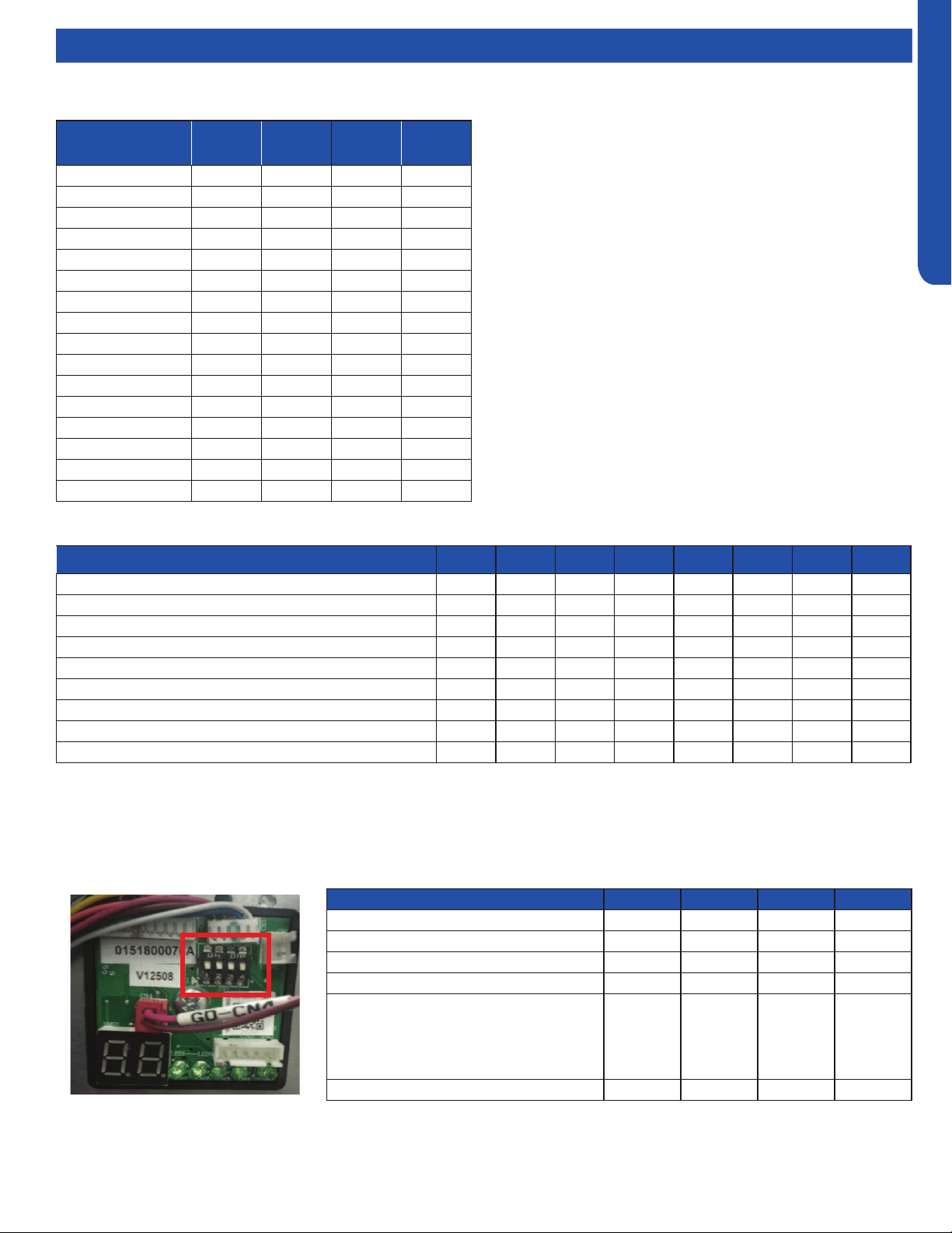
OUTDOOR TECHNICAL OVERVIEW
B-23
ENGLISH
Topic TitleDIP Switch Settings
WJ26X25054 - Service Monitor Board DIP Switch Settings
Outdoor Central
Control Address
SW6-1 SW6-2 SW6-3 SW6-4
0 OFF OFF OFF OFF
1 OFF OFF OFF ON
2 OFF OFF ON OFF
3 OFF OFF ON ON
4 OFF ON OFF OFF
5 OFF ON OFF ON
6 OFF ON ON OFF
7 OFF ON ON ON
8 ON OFF OFF OFF
9 ON OFF OFF ON
10 ON OFF ON OFF
11 ON OFF ON ON
12 ON ON OFF OFF
13 ON ON OFF ON
14 ON ON ON OFF
15 ON ON ON ON
Outdoor central control address settings
Definition SW1-1 SW1-2 SW1-3 SW1-4
Factory default OFF OFF OFF OFF
Forced heating ON OFF OFF OFF
Forced cooling OFF ON OFF OFF
Rated operation OFF OFF ON OFF
Time defrost valid: Defrost initiates if
needed when the compressor has been on
for 10 minutes continuously and 50 minutes
cumulative. Termination conditions are the
same as demand defrost.
OFF OFF OFF ON
Wiring check active* ON ON ON ON
Description SW7-1 SW7-2 SW7-3 SW7-4 SW7-5 SW7-6 SW7-7 SW7-8
USA energy efficiency test mode for High Wall unit OFF* OFF* ---- ---- ---- ---- ---- ----
USA energy efficiency test mode for Duct unit ON OFF ---- ---- ---- ---- ---- ----
Reserved ---- OFF* ---- ---- ---- ---- ----
Reserved ---- ---- ---- OFF* ---- ---- ---- ----
Reserved ---- ---- ---- ---- OFF* ---- ---- ----
Reserved ---- ---- ---- ---- ---- OFF* ---- ----
North American region ---- ---- ---- ---- ---- ---- ON* ----
Non-North American region ---- ---- ---- ---- ---- ---- OFF ----
Quiet operation valid ---- ---- ---- ---- ---- ---- ---- OFF*
SW6 DIP Switch Settings
SW1 DIP Switch Settings
SW7 DIP Switch Settings
*Factory Default Setting
*See page B-18 for Wiring Error Check.
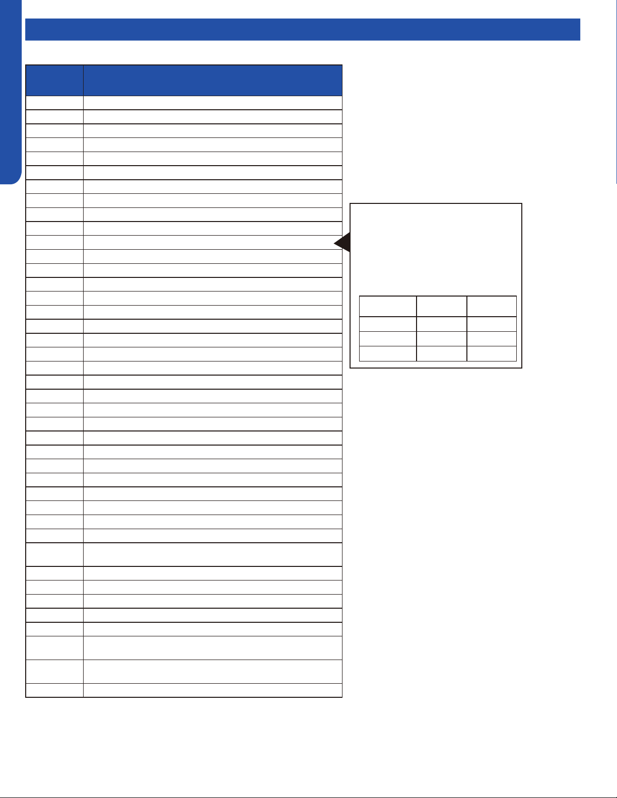
OUTDOOR TECHNICAL OVERVIEW
B-24
ENGLISH
Topic TitleError Codes
LED Error
Code
Diagnosis
1 Outdoor EEPROM failure
2 IPM overcurrent or short circuit
4 Communication failure between the IPM and outdoor PCB
5 Module operated overload (compressor overload protection)
6 Module low or high voltage
8 Overheat protection for discharge temperature
9 Malfunction of the DC fan motor
10 Malfunction of defrost temperature sensor
11 Suction temperature sensor failure
12 Ambient temperature sensor failure
13 Discharge temperature sensor failure
15 Communication failure between the indoor & outdoor unit
16 Lack of refrigerant or discharging
17 4-way valve switching failure
18 Loss of synchronism detection
20 Indoor thermal overload
21 Indoor unit overload protection, heating mode only.
21 Indoor coil frosted
23 Module thermal overload
24 Compressor start failure, over-current
25 Phase current protection (IPM)
26 MCU reset
27 Module current detect circuit malfunction
28 Liquid pipe sensor failure: Circuit A
29 Liquid pipe sensor failure: Circuit B
30 Liquid pipe sensor failure: Circuit C
31 Liquid pipe sensor failure: Circuit D
32 Gas pipe sensor failure: Circuit A
33 Gas pipe sensor failure: Circuit B
34 Gas pipe sensor failure: Circuit C
35 Gas pipe sensor failure: Circuit D
36 Gas pipe sensor failure: Circuit E
38
Malfunction of module temperature sensor momentary power failure
detection
39 Malfunction of condensing temperature sensor
40 Liquid pipe sensor failure: Circuit E
41 Toci temperature sensor failure
42 High Pressure switch open
43 Low Pressure switch open
44
System high pressure protection: Overcharged, high condensing
temperature or malfunction of fan motor.
45
System low pressure protection: Undercharged, low defrosting
temperature, or malfunction of fan motor.
L0 OAT less than -22°F (-30°C)
Precautions For Adding Refrigerant
1. This system must use refrigerant R410A.
2. Add refrigerant 0.20 oz/ft per meter
when the total piping length exceeds the
standard value.
3. The total liquid piping length must be less
than the max value.
Outdoor Unit Std. Value Max Value
2U20EH2VHA 30m/100ft. 50m/164ft.
3U24EH2VHA 30m/100ft. 60m/197ft.
4U36EH2VHA 40m/131ft. 70m/230ft.
Notes:
1. No addressing is necessary. All indoor wiring
connections must match the outdoor connections, or
a communication failure will result.
2. Set SW5-8 to ON for Quiet Operation if desired.
Maximum capacity may be slightly reduced.
3. Do not change any switch settings unless directed to
do so.
* PCB: Printed Circuit Board
* IPM: Inverter Power Module
* EEV: Electronic Expansion Valve
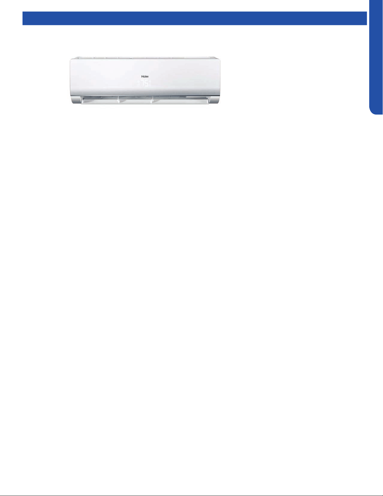
WALL MOUNT TECHNICAL OVERVIEW
C-1
ENGLISH
WALL MOUNT TECHNICAL OVERVIEW
Table of Contents
Components ......................................................................................................................................................................... C- 2
Component Overview ......................................................................................................................................................... C- 2
Indoor Wall Mount Unit Circuit Board ................................................................................................................................. C-3
Testing .................................................................................................................................................................................. C- 5
Accessing Components/Removing Cover......................................................................................................................... C-5
Indoor Fan Motor Voltage Check ........................................................................................................................................ C- 6
Replacing the Blower Motor ................................................................................................................................................ C-6
Testing Temperature Sensors ............................................................................................................................................. C-8
Testing Louver Motors ........................................................................................................................................................ C-8
Testing Communication Circuit .......................................................................................................................................... C-8
Wiring Diagram ..................................................................................................................................................................... C- 9
Error Codes ......................................................................................................................................................................... C-10
AW07EH2VHA
AW09EH2VHA
AW12EH2VHA
AW18EH2VHA
AW07LC2VHB
AW09LC2VHB
AW12LC2VHB
AW18LC2VHB
AW24LP2VHA
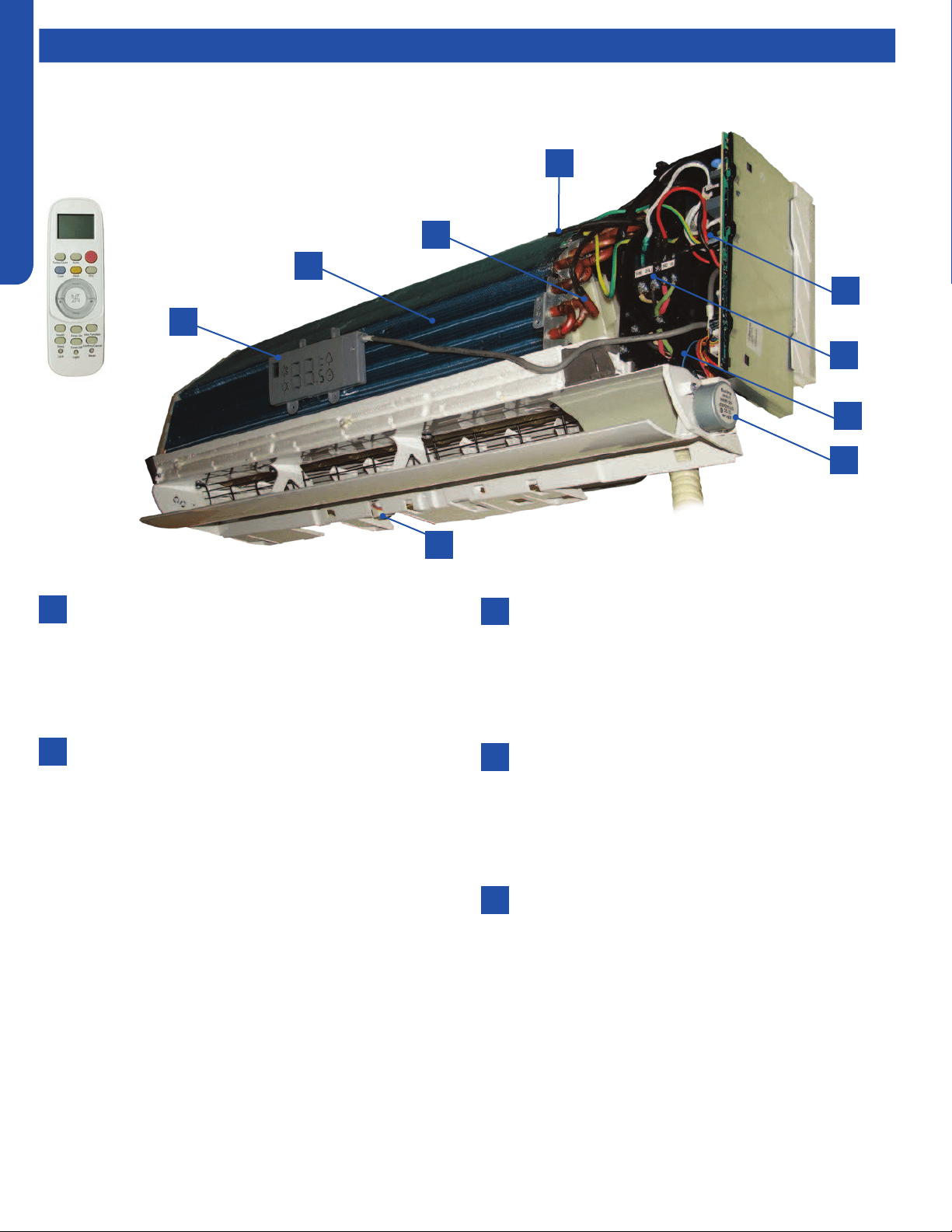
WALL MOUNT TECHNICAL OVERVIEW
C-2
ENGLISH
Components
Terminal Block
Power to operate the indoor unit comes from the
electrical line voltage terminal block at the outdoor unit.
The wiring includes 4 wires: 1, 2, 3 and ground. Wires 1
and 3 complete the data path. These wires should always
be 14 gauge AWG Stranded type wire. Splices in wires 1
or 3 may cause communication errors.
Blower Assembly
The blower assembly consists of a plastic blower wheel
that is connected to a variable speed indoor blower
motor. A set screw holds the blower wheel to the blower
motor.
The indoor blower motor is a DC Fan Motor that is
connected to the indoor unit control board. The wiring
from the motor to indoor board consists of 5 wires
connected to pins 1, 4, 5, 6 and 7. Pin 1 should have 310
VDC. Pin 4 is ground. Pin 5 +15VDC. Pin 6 is the feedback
signal. Pin 7 is the speed control.
During normal operation, the indoor control board will
energize the indoor blower motor and request proper
speed. The indoor blower motor will control the speed
via a command at the Pin 7 speed control. Proper fan
speed is veried by the indoor control board via the
voltage level at the feedback signal on Pin 6. Should
the feedback signal not be present during a call for
indoor blower, the indoor control board will indicate a
Malfunction Code E14.
Louver Stepper Motors
Separate motors located in the indoor unit control the
operation of the motorized louvers. All of the louver
motors are controlled via commands received from the
remote control. The blower motor is controlled by both
the remote control and by commands from the outdoor
unit ECU.
Pipe Temperature Sensor
The Piping Temperature Sensor senses indoor coil
temperature in the cooling mode and in the heating
mode. This sensor is used for Anti Freezing and Anti
Cold Blow cycles. The sensor also provides critical
temperature information to the ECU that may be used in
frequency adjustments.
Ambient Temperature Sensor
The ambient air sensor senses the temperature of
the air being drawn into the wall mounted unit from
the conditioned space. This sensor provides room
temperature information to the ECU for calculation of
inverter capacity and temperature control.
2
4
6
8
1
3
3
5
7
The wall mounted units act as evaporator coils during cooling mode and condenser coils during heating mode. These units have
gravity condensate drain systems. If a condensate pump is needed, it must be eld provided and mounted external to the indoor
unit.
1
2
3
4
5
The wall mount unit is shipped
with a wireless controller.
Component Overview
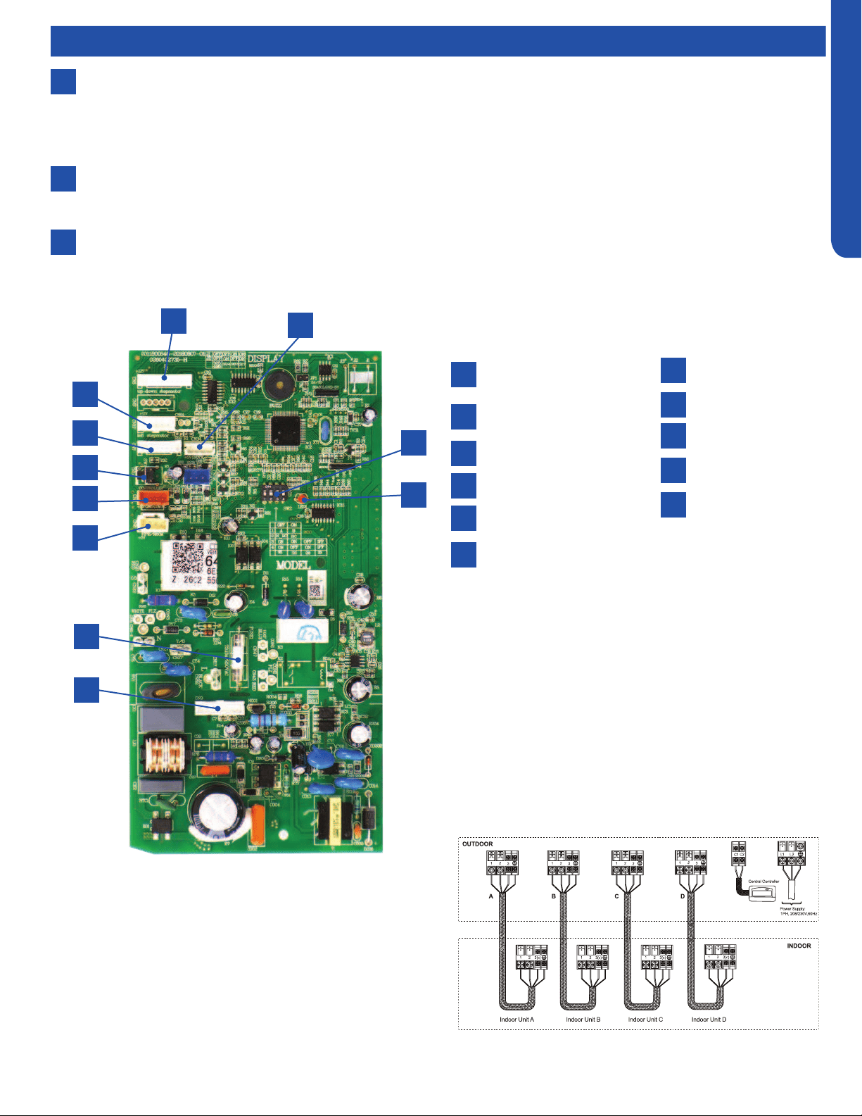
WALL MOUNT TECHNICAL OVERVIEW
C-3
ENGLISH
Up/Down Stepper
Motor
Left Stepper Motor
Display Board
Emergency Switch
Wired Controller
Temperature Sensors
15A/250VAC Fuse
DC Fan Motor
LED
DIP Switch Bank SW2
WiFi
Components
6
7
8
Display
The indoor unit has a display that communicates system mode, room temperature and diagnostic code information. The
diagnostic code information shown on the indoor unit will NOT be the same code that is displayed on the outdoor unit.
When servicing a diagnostic error, compare the indoor unit code to the outdoor unit code to make diagnostic decisions.
Codes that relate to outdoor unit problems should use the outdoor unit display information as priority.
Control Board
The indoor unit circuit board controls the switching functions of the indoor unit. All control decisions are made by the
outdoor unit ECU. The indoor board has some limited diagnostic capability which will be covered in this manual.
Evaporator Coil
Indoor Wall Mount Unit Circuit Board
1
2
3
4
5
6
7
8
9
10
11
1
2
3
4
5
6
7
8
10
11
9
The Indoor Unit Circuit Board communicates with the outdoor
unit ECU via a connection at Terminal Block screw 3.
The data pulse that sends the communication information
can be measured with a voltmeter placed to DCV range. From
the ground connection at the Terminal Block to the Number 3
screw connection, the voltage should pulse up and down when
data is being transmitted.
This control board has control over the fan louver movement,
manual fan blower control, indoor coil temperature and indoor
air temperature sensing functions. All operational decisions
are controlled by the OUTDOOR UNIT ECU. The connections
on the indoor board are shown here in the schematic drawing.
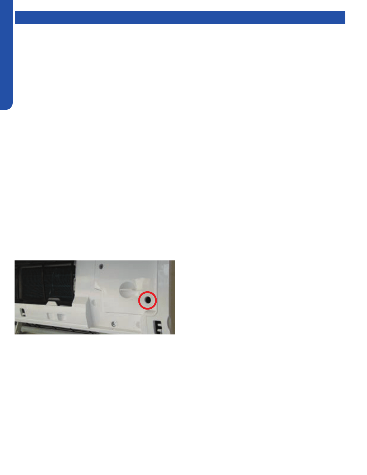
WALL MOUNT TECHNICAL OVERVIEW
C-4
ENGLISH
Topic TitleComponents
Emergency Run
Switch
Line voltage to power the indoor unit comes in on Terminal
Block connections 1 and 2. Power connects from these
terminal connections on the circuit board. If the board does
not respond to commands and has no display, check for line
voltage at these connections. When power is present at the
indoor board, the RED LED on the circuit board will blink a 2
ash code.
The control board has a replaceable 3.15A 250V fuse that
protects against excessive current. If power is present at
the board but the board does not work, check for continuity
through the fuse. Replace if the fuse is open.
The indoor unit temperature sensors are connected to the
control board. When testing the calibration of these sensors,
the wires can be released from the plug by pressing on the
tension tab on the side of the plug.
The receiver/display unit that is mounted to the front cover of
the indoor unit plugs into the control board.
There are two to three motors connected to the control board
that control the movement of the louvers right, left and up/
down. Some units will use one motor to operate the right and
left movement function.
The blower motor is connected to the circuit board.
There is an Emergency Run switch on the edge of the indoor
board that will put the system into Auto Mode should the
remote control break or be lost. When this switch is pressed
and held for 5 seconds, the indoor unit display will beep twice
and the system will enter TEST MODE.
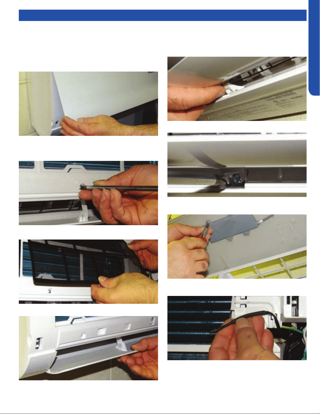
WALL MOUNT TECHNICAL OVERVIEW
C-5
ENGLISH
Testing
6. Open the 3 caps that cover the screws located behind the
bottom of the louver. These caps ip up.
1. To access components for service, rst disconnect power
to the outdoor unit. This will de-energize the indoor unit.
2. Lift the front cover by prying on the two indented nger
holds at each end of the indoor unit.
3. Remove the three Phillips head screws located near the
bottom of the indoor unit. These screws are located
directly below the bottom of the air lter.
4. Remove the lters.
5. Manually open the louver.
7. Remove the three screws located behind the caps.
8. Remove the two screws that hold the digital display to the
front cover. The display can hang free.
9. Release the air temperature sensor from the clip that
holds it.
10. Pull upward on the top of the indoor unit cover to free
it from the four retaining clips. The cover will pivot
downward. The cover should now pull away from the
indoor unit.
Accessing Components/Removing Cover
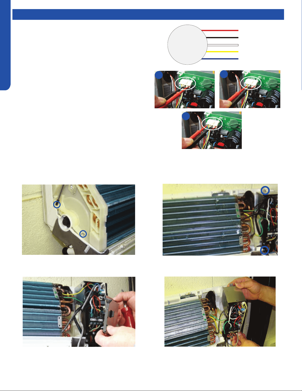
WALL MOUNT TECHNICAL OVERVIEW
C-6
ENGLISH
Testing
If The Indoor Fan Motor Does Not Run:
1. Remove the front cover and access the circuit board fan motor
connection.
2. Reset power and turn the remote control fan command to Fan
On mode.
1. Disconnect the power.
2. With the indoor unit cover removed, remove the two
screws on the left plastic evaporator coil bracket.
Motor Test:
1. If the motor doesn’t run, check for 310VDC between Pins 1
and 3. If it is not present, the indoor board is bad. If voltage
is present, continue on.
2. Check the voltage between Pins 3 and 4. The voltage
should be +15VDC. If it is not present, the board is bad. If
voltage is present, continue on.
3. Check for voltage between Pins 3 and 6. If no DC voltage is
present, the board is bad. If voltage is present, change the
motor.
3. Remove the cover from the electrical box on the right side
of the indoor unit.
4. Remove the two screws that hold the electrical box in
place.
5. Lift and swing the electrical box out of the way.
Indoor Fan Motor Voltage Check
Replacing the Blower Motor
1
2
3
DC Motor
+310 VDC
DC Ground
+15 VDC
Signal
Feedback
Red
Black
White
Yellow
Blue
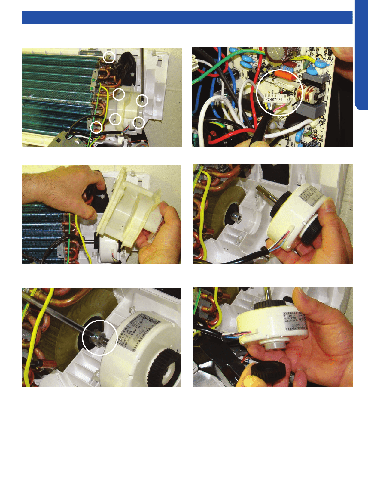
WALL MOUNT TECHNICAL OVERVIEW
C-7
ENGLISH
Testing
6. Remove 6 screws that hold the motor bracket and
evaporator coil.
7. Lift the evaporator coil and remove the motor bracket.
8. Loosen the motor shaft set screw. Phillips head screw.
9. Unplug the motor from the circuit board.
10. Lift and slide the motor away from the blower wheel.
11. Remove the two black anti vibration mounts from the
defective motor and place them on the new motor.
12. Install new motor in reverse order.
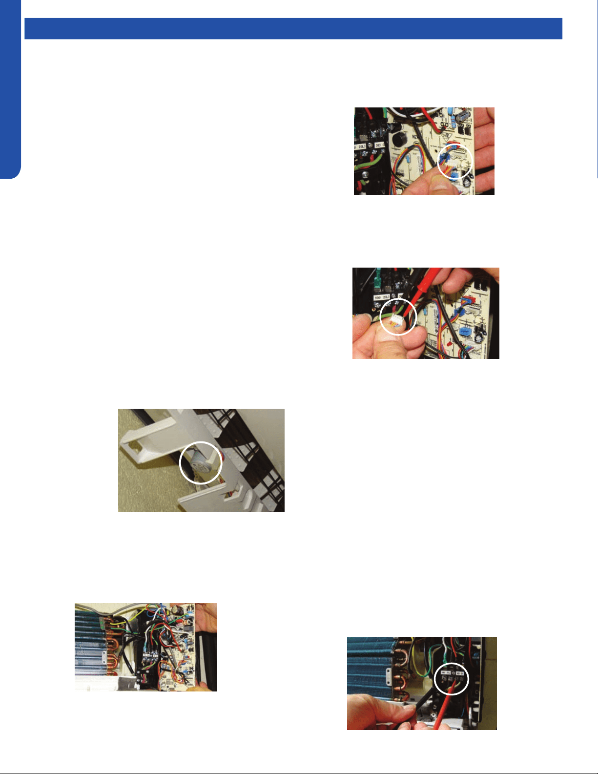
WALL MOUNT TECHNICAL OVERVIEW
C-8
ENGLISH
Testing
Testing Temperature Sensors
The easiest problems to solve will involve codes that are
related to potential failure of temperature sensors. Common
problems may include loose connections, open electrically,
and out of calibration. Checking the condition of the sensors
requires a temperature probe and an ohmmeter.
The Reference Section of this manual contains temperature
resistance tables that can be used to check the calibration
of the sensors. The measured resistance must be within the
tolerances printed on the top of the tables.
To test the electrical condition of a temperature sensor
perform the following:
1. Conrm the sensor is rmly attached to the circuit
board connection plug.
2. Remove the sensor wires from the connection plug by
releasing holding tension on the plugs tension tab.
3. Use an ohmmeter to test the electrical resistance of the
sensor.
4. Measure the air temperature near the sensor and compare
the required resistance against measured resistance.
(See chart in reference section) If the sensor is within
calibration, the sensor is good. If the sensor is out of
calibration, replace the sensor. (Tube Sensors should be
removed from socket and exposed to air temperature
during test.)
Testing Louver Motors
If the louver does
not operate with
command from the
remote control,
either the indoor
board is bad, or
the louver motor is
defective. It is more
likely the motor is
defective than the board. (Make sure the louver assembly is
not binding and keeping the vanes from moving.)
1. Remove power from the unit and remove the indoor unit
cover.
2. Access the circuit board.
Testing Communication Circuit
If an Error E7 occurs, perform the following test to determine
if the indoor control board is functioning properly to send data
to the outdoor unit.
Perform this test with the unit powered and all wiring
connected between indoor and outdoor unit.
Make sure all wiring between the indoor and outdoor unit
are correct. There should no splices between the indoor and
outdoor unit wiring connecting terminals 1 or 3. Make sure
wiring is correct, before performing this test.
1. Measure the DC voltage between terminals 1 and 3 on the
indoor terminal block.
2. C and 23VDC. The uctuating signal indicates a good
communication path.
3. If the voltage does not uctuate, and the wiring is good,
the indoor board is defective.
3. Identify on the schematic drawing the inoperable louver
motor and disconnect the plug from the circuit board. (The
up down louver motor is located on the right side of the
indoor unit. The left right louver motor is located bottom
center. )
4. Use an Ohmmeter to test the electrical continuity of the
louver motor windings. The proper resistance for each
winding can be found in this table. If the motor winding
resistance is erratic or shows open, the motor is defective.
Replace the motor.
5. If the motor checks out good, replace the indoor control
board.
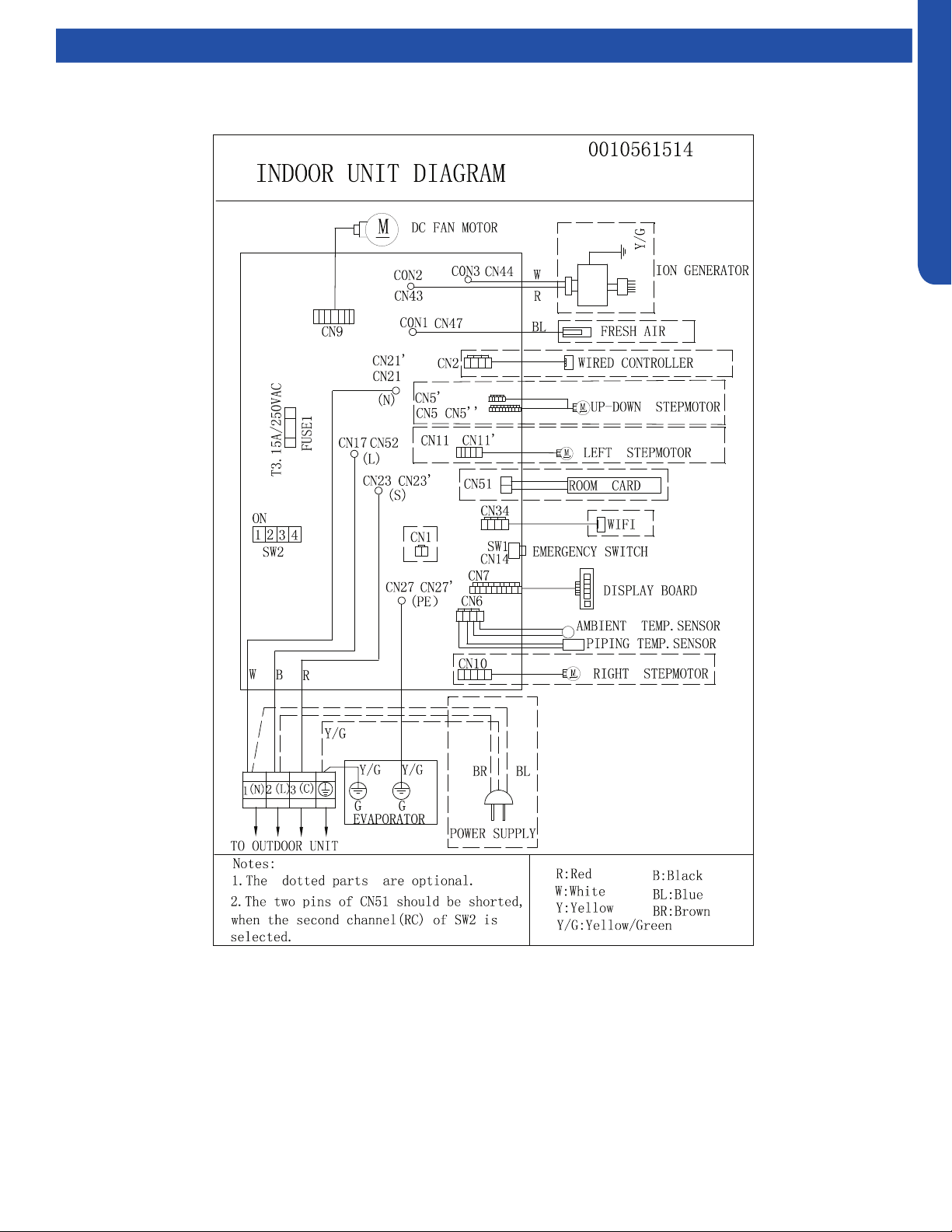
WALL MOUNT TECHNICAL OVERVIEW
C-9
ENGLISH
Topic Title Wiring Diagrams
WALL MOUNT TECHNICAL OVERVIEW
C-10
ENGLISH
Error Codes
The error codes that are displayed on the indoor units may vary from the outdoor unit codes. The information communicated by
the error code will be the SAME for both indoor and outdoor units even though the numbers may dier.
Indoor
Display
Outdoor
LED
Diagnosis
F12 1 Outdoor EEPROM failure
F1 2 IPM overcurrent or short circuit
F22 / Outdoor alternating current, over current protection
F3 4 Communication failure between the IPM and outdoor PCB
F20* 5 Module operated overload (compressor overload protection)
F19* 6 Module low or high voltage
F27 / Compressor current sampling circuit fault
F4 8 Overheat protection for discharge temperature
F8* 9 Malfunction of the DC fan motor
F21 10 Malfunction of defrost temperature sensor
F7 11 Suction temperature sensor failure
F6 12 Ambient temperature sensor failure
F25 13 Discharge temperature sensor failure
F30* / High outdoor suction temperature
E7 15 Communication failure between the indoor & outdoor unit
F13* 16 Lack of refrigerant or discharging
F14* 17 4-way valve switching failure
F11 18 Loss of synchronism detection
F28 / Position detection circuit fault of compressor
F15* / Terminal block temp too high
E9 20 Indoor thermal overload
E9* 21 Indoor unit overload protection, heating mode only.
E5 21 Indoor coil frosted
E5* / Indoor anti-frosting protection
F5* 23 Module thermal overload
F2* 24 Compressor start failure, over-current
F23* 25 Phase current protection (IPM)
F9 26 MCU reset
F24 27 Module current detect circuit malfunction
F10 28 Liquid pipe sensor failure: Circuit A
F16 29 Liquid pipe sensor failure: Circuit B
F17 30 Liquid pipe sensor failure: Circuit C
F18 31 Liquid pipe sensor failure: Circuit D
F29 32 Gas pipe sensor failure: Circuit A
F30 33 Gas pipe sensor failure: Circuit B
F31 34 Gas pipe sensor failure: Circuit C
F32 35 Gas pipe sensor failure: Circuit D
F26 36 Gas pipe sensor failure: Circuit E
F34 / Outdoor pipe temperature protection in cooling mode
F35 38 Malfunction of module temperature sensor momentary power failure detection
F36 39 Malfunction of condensing temperature sensor
F33 40 Liquid pipe sensor failure: Circuit E
F38 41 Toci temperature sensor failure
F39 42 High Pressure switch open
F40 43 Low Pressure switch open
F41 44 System high pressure protection: Overcharged, high condensing temperature or malfunction of fan motor.
F42 45 System low pressure protection: Undercharged, low defrosting temperature, or malfunction of fan motor.
F43 / Incorrect match between indoor & outdoor
E1 / Indoor ambient temperature sensor failure
E2 / Indoor coil temperature sensor failure
E4 / Indoor PCB EEPROM failure
E14* / Indoor fan motor malfunction
* Hidden indoor error code. LED1 will ash outdoors, but no error will appear on indoor unit display. To view error code on indoor display, press and hold the
Emergency button for 15 seconds.
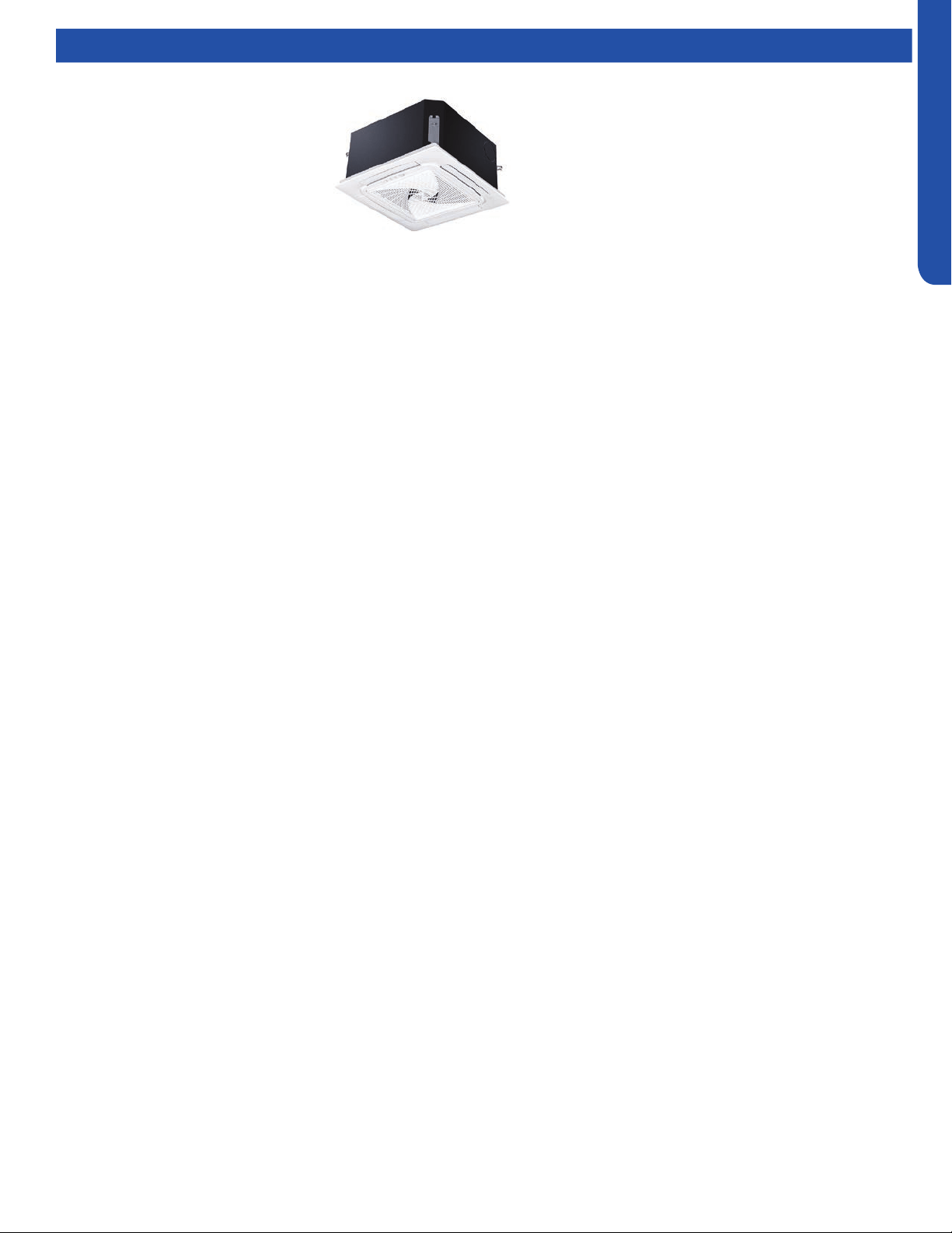
COMPACT CASSETTE TECHNICAL OVERVIEW
D-1
ENGLISH
COMPACT CASSETTE TECHNICAL OVERVIEW
Table of Contents
Components ......................................................................................................................................................................... D-2
Component Overview ......................................................................................................................................................... D-2
Cassette Unit Indoor Circuit Board .....................................................................................................................................D-4
Testing .................................................................................................................................................................................. D-5
Accessing the Blower Motor and Condensate Pump ........................................................................................................D-5
Removing Fan Motor ...........................................................................................................................................................D-5
Removing Condensate Pump .............................................................................................................................................D-5
Indoor Fan Motor Test Procedure .......................................................................................................................................D-6
Testing Temperature Sensors .............................................................................................................................................D-6
Testing Louver Motors ........................................................................................................................................................D-7
Testing Communication Circuit ..........................................................................................................................................D-7
Test Condensate Pump and Associated Float Switch .......................................................................................................D-8
Wiring Diagram & DIP Switch Settings ..................................................................................................................................D-9
Error Codes .........................................................................................................................................................................D-10
AB09SC2VHA
AB12SC2VHA
AB18SC2VHA
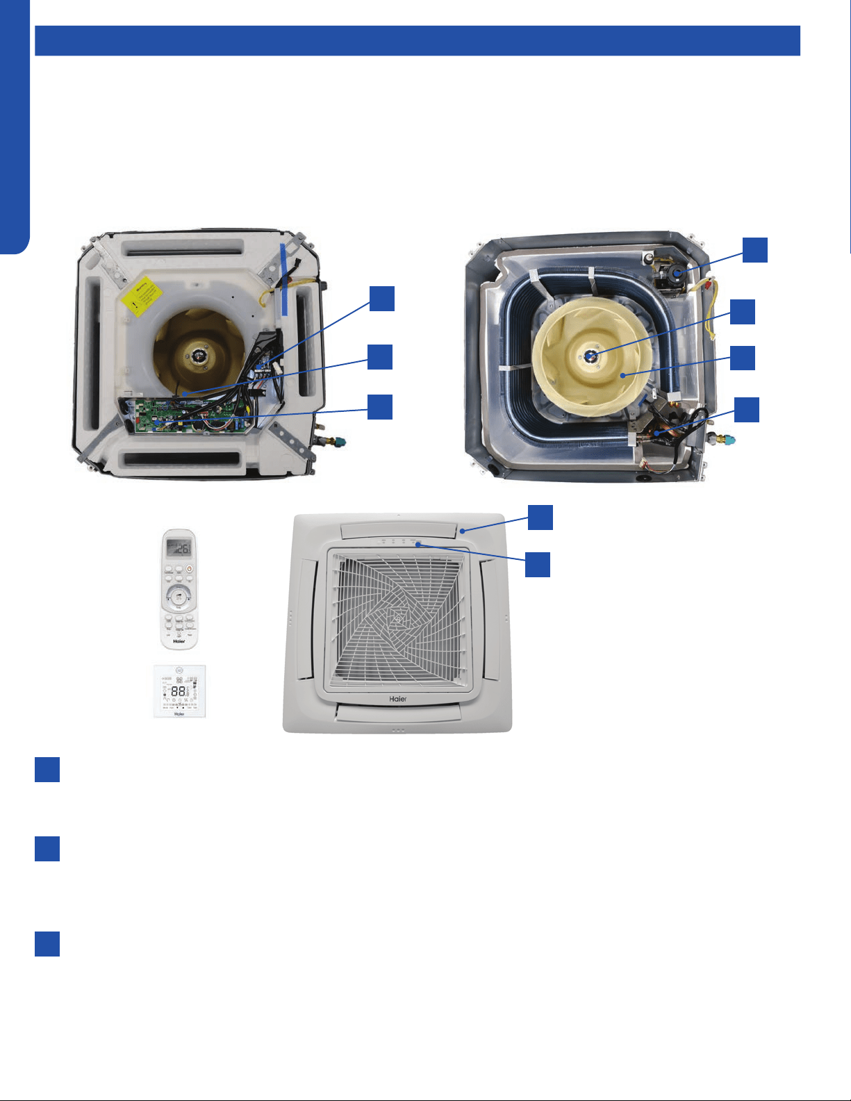
COMPACT CASSETTE TECHNICAL OVERVIEW
D-2
ENGLISH
Components
The indoor cassette type units act as evaporator coils during cooling mode and condenser coils during heating mode. These
units have a built in condensate pump with an associated condensate level switch. The condensate pump is capable of lifting
water out of the indoor unit. If high water lift is needed, the water from the cassette pump should be pumped into a eld supplied
condensate pump with high lift power.
Cassette type indoor units can be operated with a wired controller or a remote control.
Terminal Block
Power to operate the indoor unit comes from the electrical line voltage terminal block at the outdoor unit. The wiring
includes 4 wires, 1, 2, 3 and ground. Wires 1 and 3 complete the data path. These wires should always be 14 gauge AWG
Stranded type wire. Splices in wires 1 or 3 may cause communication errors.
Motor Blower
The indoor unit features a multi speed blower motor that will change speed to match the capacity demand from the
outdoor unit. Separate motors located in the indoor unit control the operation of the motorized louvers. All of the louver
motors are controlled via commands received from the remote control. The blower motor is controlled by both the remote
control and by commands from the outdoor unit ECU.
Display
The indoor unit has a display that communicates system mode. The indoor unit does not display temperatures or
diagnostic codes. When a wired controller is used, this information is displayed on the wired controller. It is recommended
to use a wired controller with the cassette unit.
When servicing a diagnostic error, ALWAYS refer to the outdoor unit code to make diagnostic decisions.
Component Overview
1
7
8
3
5
9
2
4
6
1
2
3

COMPACT CASSETTE TECHNICAL OVERVIEW
D-3
ENGLISH
Topic TitleComponents
The Blower Assembly
The blower assembly consists of a plastic blower wheel that is connected to a PSC indoor blower motor. A set screw holds
the blower wheel to the blower motor.
The indoor blower motor is a Multi Speed Fan Motor that is connected to the indoor unit control board. The wiring from the
motor to indoor board consists of 4 wires connected to pins common, low , medium and high speeds.
During normal operation, the indoor control board will energize the indoor blower motor and request proper speed. The
motor has a run capacitor that is located in the Cassette unit’s control box. The run capacitor connects to the motor via
two orange wires. This capacitor is eld replaceable.
Louver Motors
The louver motors are stepper type motors that move the louvers up/down. The motors are controlled by pulsed voltage
that cannot be measured. If the louver does not move when it should, check for a bind in the louvers.
Piping Temperature Sensor
The Piping Temperature Sensor senses indoor coil temperature in the cooling mode and in the heating mode. This sensor is
used for Anti Freezing and Anti Cold Blow cycles. The sensor also provides critical temperature information to the ECU that
may be used in frequency adjustments.
Ambient Temperature Sensor
The Ambient Temperature Sensor senses room temperature. This sensor provides room temperature information to the
ECU for calculation of inverter capacity and temperature control.
Both sensors are negative temperature coecient type that reduce electrical resistance as temperature rises.
Control Board
The indoor unit circuit board controls the switching functions of the indoor unit. All control decisions are made by the
outdoor unit ECU. The indoor board has some limited diagnostic capability which will be covered in this manual.
Condensate Pump & Float Switch
4
5
6
7
8
9
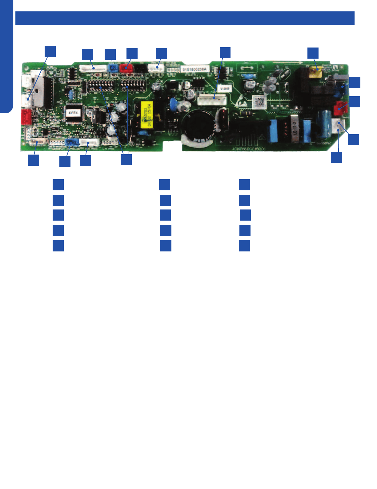
COMPACT CASSETTE TECHNICAL OVERVIEW
D-4
ENGLISH
Topic TitleComponents
The indoor unit circuit board controls the switching functions
of the indoor unit. All control decisions are made by the
outdoor unit ECU. The indoor board has some limited
diagnostic capability which will be covered in this manual.
The Indoor Unit Circuit Board communicates with the outdoor
unit ECU via a connection at Terminal Block screw 3. The
data pulse that sends the communication information can be
measured with a voltmeter placed to DCV range. From the
ground connection at the Terminal Block to the Number 3
screw connection, the voltage should pulse up and down when
data is being transmitted.
This control board has control over the fan louver movement,
manual fan blower control, indoor coil temperature and indoor
air temperature sensing functions. All operational decisions
are controlled by the OUTDOOR UNIT ECU.
The connections on the indoor board are shown here in the
schematic drawing.
Line voltage to power the indoor unit comes in on Terminal
Block connections 1 and 2. Power connects from these
terminal connections to CH- 3 and CH-4 on the circuit board.
If the board does not respond to commands and has no
display, check for line voltage at these connections. When
power is present at the indoor board, the Display Power
Indicator will be lit.
The control board has a replaceable 3.15A 250V fuse that
protects against excessive current. If power is present at
the board but the board does not work, check for continuity
through the fuse. Replace if the fuse is open.
The indoor unit temperature sensors are connected at
Plug CN-13. When testing the calibration of these sensors,
the wires can be released from the plug by pressing on the
tension tab on the side of the plug.
The receiver/display unit that is mounted to the front
cover of the indoor unit plugs into the circuit board via a
connection at Plug CN-29.
There is one motor that controls the movement of the
louvers. The motor connects to the circuit board at Plug CN-
14. The motor is located in the over of the louver assembly.
The blower/fan motor is connected to the circuit board at
plug CN-11.
The Cassette unit has a built in condensate pump. The pump
is connected to the circuit board on Plug CN-9. The pump
is energized whenever the Float Switch indicates that water
needs to be pumped from the cassette. The oat switch
connects onto the circuit board via Plug CN-18.
1
4
7
10
13
2
5
8
11
14
3
N Terminal
L Terminal
Communication Terminal
3.15A 250V Fuse
CN3 Pipe/Room Temp Sensors
1
4
2
5
3
6
9
12
15
7
10
8
6
9
CN19 Float Switch
CN21 Louver Panel
CN11 Wired Remote
DIP Switches
CN35 Stepper Motor
13
11
14
12
15
CN6 Fan Motor
CN9 Condensate Pump
CN4 U-HOME
CN13 Remote Central
CN1 Room Card
Cassette Unit Indoor Circuit Board
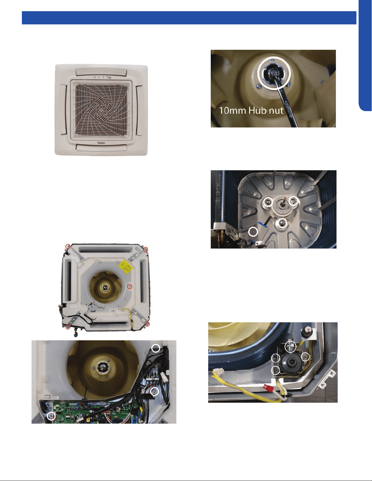
COMPACT CASSETTE TECHNICAL OVERVIEW
D-5
ENGLISH
Testing
Accessing the Blower Motor and Condensate Pump
1. Disconnect power to the outdoor unit.
2. Remove the louver assembly.
Removing Fan Motor
1. Remove holding nut from fan blade.
Removing Condensate Pump
1. Remove screws holding condensate pump and oat switch
in position.
2. Disconnect condensate hose from condensate pump.
3. Remove assembly.
8. Slide condensate pan from cassette.
2. Fan blade will slide o motor shaft.
3. Remove Phillips head screw holding cover plate over motor
wiring leads.
4. Remove 3 nuts that hold fan motor in place.
5. Fan motor will come loose.
3. Disconnect the main power wire to the indoor unit.
4. Unplug the condensate pump and oat switch from wiring
harness.
5. Unplug fan motor from wiring harness.
6. Remove ground wire from ground screw on electrical
box. Remove electrical box.
7. Remove 5 screws holding foam condensate pan bottom in
place.
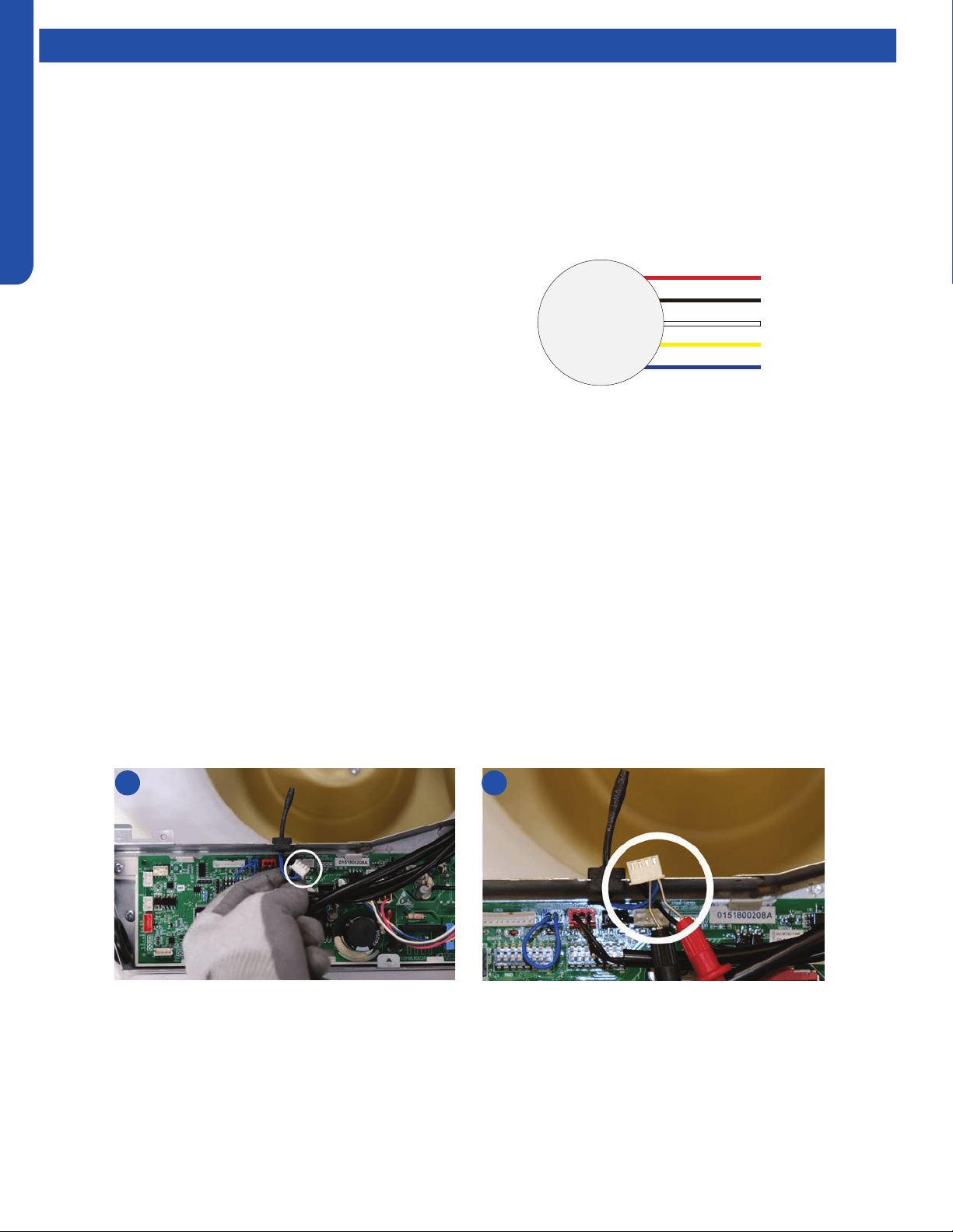
COMPACT CASSETTE TECHNICAL OVERVIEW
D-6
ENGLISH
Testing
Indoor Fan Motor Test Procedure
If the indoor fan motor does not run:
1. Disconnect power to the system.
2. Remove the return air cover and access the circuit board connection.
3. Reset power and turn the remote control fan command to Fan On mode.
Testing Temperature Sensors
The easiest problems to solve will involve codes that are related to potential failure of temperature sensors. Common problems
may include loose connections, open electrically, and out of calibration. Checking the condition of the sensors requires a
temperature probe and an ohmmeter.
The Reference Section of this manual contains temperature resistance tables that can be used to check the calibration of the
sensors. The measured resistance must be within the tolerances printed on the top of the tables.
To test the electrical condition of a temperature sensor perform the following:
1. Conrm the sensor is rmly attached to the circuit board connection plug.
2. Remove the sensor wires form the connection plug by releasing holding tension on the plugs tension tab.
3. Use an ohmmeter to test the electrical resistance of the sensor.
4. Measure the air temperature near the sensor and compare the required resistance against measured resistance. (See chart in
reference section) If the sensor is within calibration, the sensor is good. If the sensor is out of calibration, replace the sensor.
(Tube Sensors should be removed from socket and exposed to air temperature during test.)
Motor Test:
1. If the motor doesn’t run, check for 310VDC between Pins 1
and 3. If it is not present, the indoor board is bad. If voltage
is present, continue on.
2. Check the voltage between Pins 3 and 4. The voltage
should be +15VDC. If it is not present, the board is bad. If
voltage is present, continue on.
3. Check for voltage between Pins 3 and 6. If no DC voltage
is present, the board is bad. If voltage is present, change
the motor.
2 4
DC Motor
+310 VDC
DC Ground
+15 VDC
Signal
Feedback
Red
Black
White
Yellow
Blue
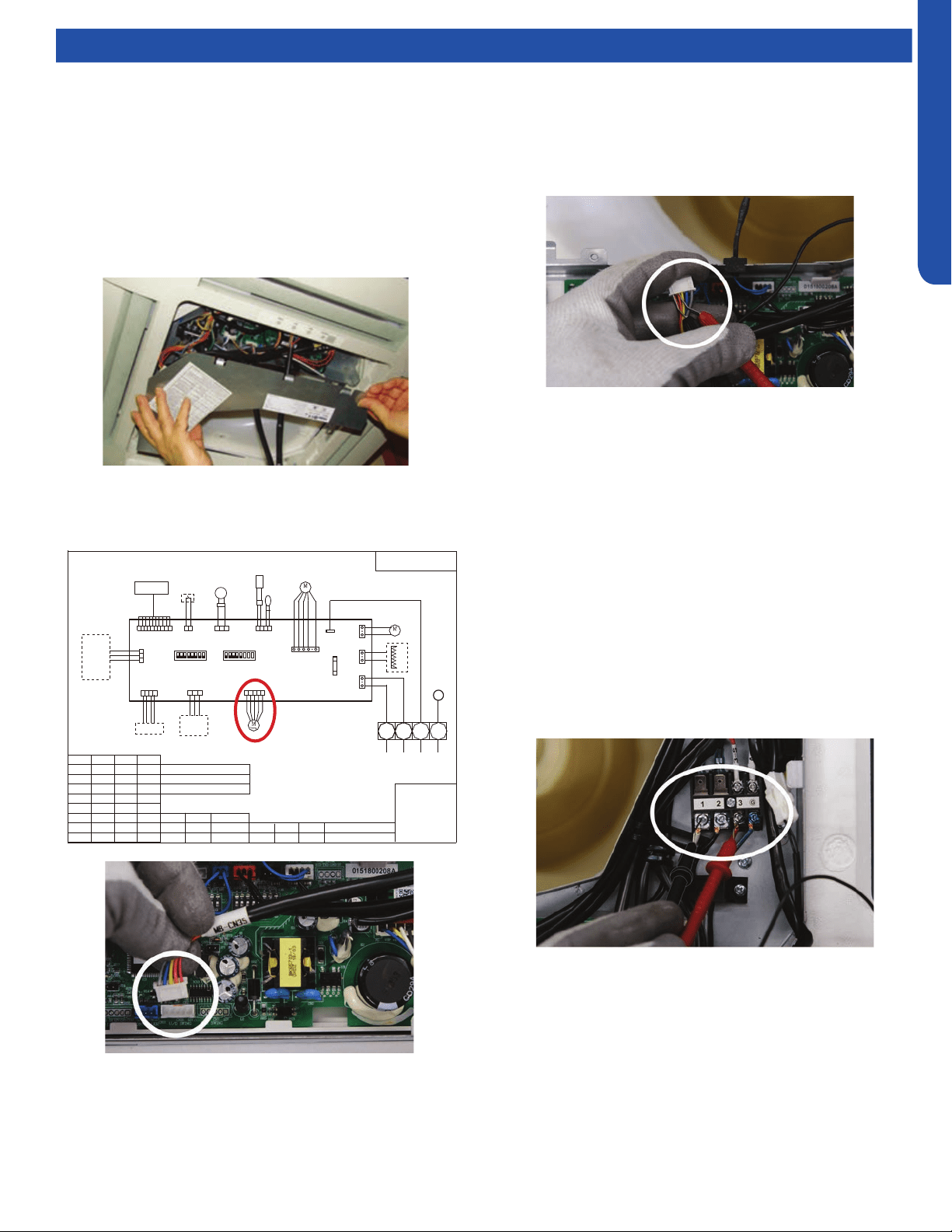
COMPACT CASSETTE TECHNICAL OVERVIEW
D-7
ENGLISH
TO OUT DOOR
0150515406
BM1-1
BM1-7
BM1-8
TYPE DEFINE
OFFOFF
BM1-2 BM1-3
BTU
B:BLACK
R:RED
W:WHITE
Y/G:YELLOW/GREEN
TEMP.
SENSOR
ROOM
SENSOR
FLOAT
SWITCH
HEATER
PUMP
UP/DOWN
CN9
CN1
CN6
PANNEL
CN4
CN11
CN19
CN13
CN3
ON
CN35
CN21
T5A/250VAC
FUSE
BM3
2
1
3
B
W
R
Y/G
OFF OFF OFF
ON OFF OFF
OFF ON OFF
ON ON OFF
OFF OFF ON
ON OFF ON
OFF ON ON
ON ON ON
9000
12000
18000
24000
28000
36000
48000
60000
NOTE1.DASHED PART ARE OPTIONAL.
2.
USER SHOULD NOT TO SET BM1 AND BM3
CH1
OFF OFF
BM1-4
BM1-5
BM1-6
OFF
OFF
CN16
G
CN8
G
TEMP.
PIPING
DC FAN
ROOMCARD
U-HOME
WIRED
CONTROLLER
BA
C
BA
C
REMOTE
CENTRAL
87654321
ON
BM1
OFF
87654321
N
OFF
Room card
available
unavailable
ON
AB09SC2VHA/AB09CS2ERA
AB12SC2VHA/AB12CS2ERA(S)
AB18SC2VHA/AB18CS2ERA(S)
Default
Testing
Testing Louver Motors
If the louver does not operate with command from the remote
control, either the indoor board is bad, or the louver motor
is defective. It is more likely the motor is defective than the
board. (Make sure the louver assembly is not binding and
keeping the vanes from moving.)
1. Remove power from the unit and remove the indoor unit
cover.
2. Access the circuit board.
3. Identify the inoperable louver motor on the schematic
drawing below and disconnect the plug from the circuit
board.
4. Use an Ohmmeter to test the electrical continuity of the
louver motor windings. The proper resistance for each
winding can be found in this table. If the motor winding
resistance is erratic or shows open, the motor is defective.
Replace the motor.
5. If the motor checks out good, replace the indoor control
board.
Testing Communication Circuit
If an Error E7 occurs, perform the following test to determine
if the indoor control board is functioning properly to send data
to the outdoor unit.
Perform this test with the unit powered and all wiring
connected between indoor and outdoor unit.
Make sure all wiring between the indoor and outdoor unit
are correct. There should no splices between the indoor and
outdoor unit wiring connecting terminals 1 or 3. Make sure
wiring is correct, before performing this test.
1. Measure the DC voltage between terminals 1 and 3 on the
indoor terminal block.
2. The voltage should uctuate between 8VDC and 23VDC.
The uctuating signal indicates a good communication
path.
3. If the voltage does not uctuate, and the wiring is good,
the indoor board is defective.
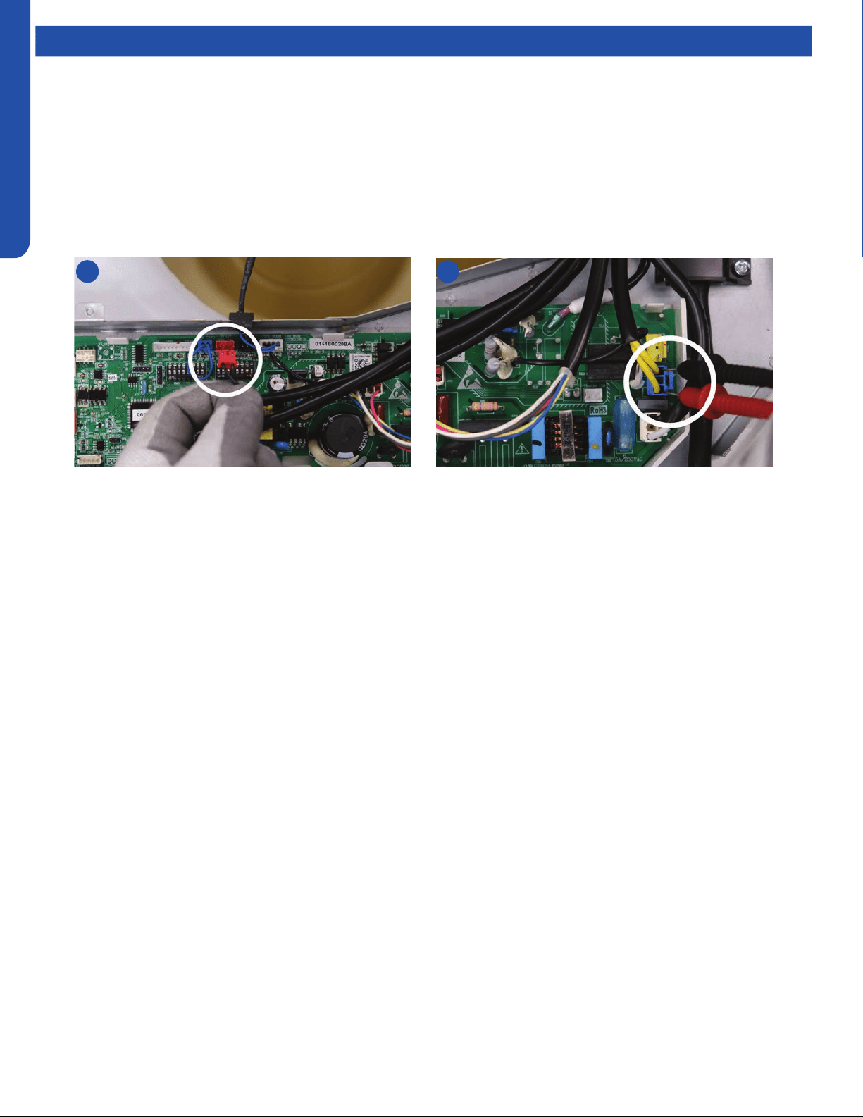
COMPACT CASSETTE TECHNICAL OVERVIEW
D-8
ENGLISH
Testing
Test Condensate Pump and Associated Float Switch
If the internal condensate pump does not operate, the pump may be bad or the oat switch may be defective. Perform the
following test:
1. Access the electrical control box.
2. Unplug the oat switch from the circuit board.
3. The pump should start.
4. If the pump does not start, check for voltage at the pump connector on the board. There should be 230 Volts AC to the pump.
If there is not, the circuit board is defective. If there is proper voltage to the pump, either the pump or associated pump wiring
is defective.
2 4
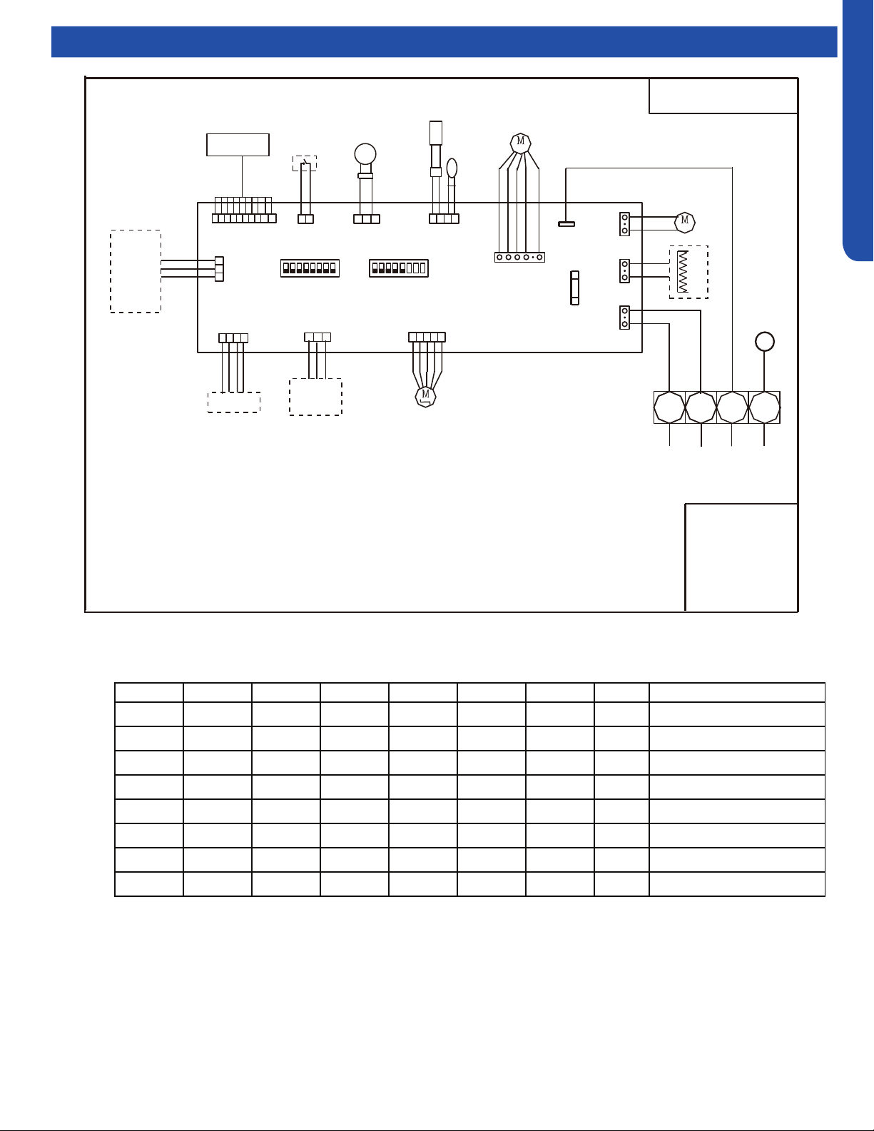
COMPACT CASSETTE TECHNICAL OVERVIEW
D-9
ENGLISH
Wiring Diagram & DIP Switch Settings
BM1-1 BM1-2 BM1-3 BM1-4 BM1-5 BM1-6 BM1-7 BM1-8 Description
OFF OFF OFF -- -- -- -- -- Unit capacity: 9000
ON OFF OFF -- -- -- -- -- Unit capacity: 12000
OFF ON OFF -- -- -- -- -- Unit capacity: 18000
-- -- -- OFF -- -- -- -- Room card invalid(default)
-- -- -- ON -- -- -- -- Room card valid
-- -- -- -- OFF -- -- -- Heat pump( defult)
-- -- -- -- ON -- -- -- Cooling only
-- -- -- -- OFF OFF OFF Cassette(American)
Dip switch setting for Cassette :0151800208A
74
BM3 the dip switch setting is reserved
Cassette Unit DIP Switch Settings
TO OUT DOOR
0150515406
BM1-1
BM1-7
BM1-8
TYPE DEFINE
OFFOFF
BM1-2 BM1-3
BTU
B:BLACK
R:RED
W:WHITE
Y/G:YELLOW/GREEN
TEMP.
SENSOR
ROOM
SENSOR
FLOAT
SWITCH
HEATER
PUMP
UP/DOWN
CN9
CN1
CN6
PANNEL
CN4
CN11
CN19
CN13
CN3
ON
CN35
CN21
T5A/250VAC
FUSE
BM3
2
1
3
B
W
R
Y/G
OFF OFF OFF
ON OFF OFF
OFF ON OFF
ON ON OFF
OFF OFF ON
ON OFF ON
OFF ON ON
ON ON ON
9000
12000
18000
24000
28000
36000
48000
60000
NOTE1.DASHED PART ARE OPTIONAL.
2.
USER SHOULD NOT TO SET BM1 AND BM3
CH1
OFF OFF
BM1-4
BM1-5
BM1-6
OFF
OFF
CN16
G
CN8
G
TEMP.
PIPING
DC FAN
ROOMCARD
U-HOME
WIRED
CONTROLLER
BA
C
BA
C
REMOTE
CENTRAL
87654321
ON
BM1
OFF
87654321
N
OFF
Room card
available
unavailable
ON
AB09SC2VHA/AB09CS2ERA
AB12SC2VHA/AB12CS2ERA(S)
AB18SC2VHA/AB18CS2ERA(S)
Default
COMPACT CASSETTE TECHNICAL OVERVIEW
D-10
ENGLISH
Error Codes
The error codes that are displayed on the indoor units may vary from the outdoor unit codes. The information communicated by
the error code will be the SAME for both indoor and outdoor units even though the numbers may dier.
Indoor
LED5
Indoor
LED1
Outdoor
LED
Diagnosis
2 1 1 Outdoor EEPROM failure
2 2 2 IPM overcurrent or short circuit
2 3 / Outdoor alternating current, over current protection
2 4 4 Communication failure between the IPM and outdoor PCB
2 5 5 Module operated overload (compressor overload protection)
2 6 6 Module low or high voltage
2 7 / Compressor current sampling circuit fault
2 8 8 Overheat protection for discharge temperature
2 9 9 Malfunction of the DC fan motor
3 0 10 Malfunction of defrost temperature sensor
3 1 11 Suction temperature sensor failure
3 2 12 Ambient temperature sensor failure
3 3 13 Discharge temperature sensor failure
3 4 / High outdoor suction temperature
3 5 15 Communication failure between the indoor & outdoor unit
3 6 16 Lack of refrigerant or discharging
3 7 17 4-way valve switching failure
3 8 18 Loss of synchronism detection
3 9 / Position detection circuit fault of compressor
4 0 / Terminal block temp too high
4 0 20 Indoor thermal overload
4 1 21 Indoor unit overload protection, heating mode only.
4 1 21 Indoor coil frosted
4 2 / Indoor anti-frosting protection
4 3 23 Module thermal overload
4 4 24 Compressor start failure, over-current
4 5 25 Phase current protection (IPM)
4 6 26 MCU reset
4 7 27 Module current detect circuit malfunction
4 8 28 Liquid pipe sensor failure: Circuit A
4 9 29 Liquid pipe sensor failure: Circuit B
5 0 30 Liquid pipe sensor failure: Circuit C
5 1 31 Liquid pipe sensor failure: Circuit D
5 2 32 Gas pipe sensor failure: Circuit A
5 3 33 Gas pipe sensor failure: Circuit B
5 4 34 Gas pipe sensor failure: Circuit C
5 5 35 Gas pipe sensor failure: Circuit D
5 6 36 Gas pipe sensor failure: Circuit E
5 7 / Outdoor pipe temperature protection in cooling mode
5 8 38 Malfunction of module temperature sensor momentary power failure detection
5 9 39 Malfunction of condensing temperature sensor
6 0 40 Liquid pipe sensor failure: Circuit E
6 1 41 Toci temperature sensor failure
6 2 42 High Pressure switch open
6 3 43 Low Pressure switch open
6 4 44 System high pressure protection: Overcharged, high condensing temperature or malfunction of fan motor
6 5 45 System low pressure protection: Undercharged, low defrosting temperature, or malfunction of fan motor
6 6 / Incorrect match between indoor & outdoor
0 1 / Indoor ambient temperature sensor failure
0 2 / Indoor coil temperature sensor failure
0 4 / Indoor PCB EEPROM failure
0 7 / Communication fault between the indoor and outdoor unit
0 8 / Communication fault between the controller and Indoor unit
0 12 / Drain system malfunction
0 13 / Zero cross signal detected wrong
0 14 / Indoor fan motor malfunction

LARGE CASSETTE TECHNICAL OVERVIEW
E-1
ENGLISH
LARGE CASSETTE TECHNICAL OVERVIEW
Table of Contents
Components ..........................................................................................................................................................................E-2
Component Overview ..........................................................................................................................................................E-2
Cassette Unit Indoor Circuit Board ......................................................................................................................................E-4
Testing ...................................................................................................................................................................................E- 5
Accessing the Blower Motor and Condensate Pump .........................................................................................................E-5
Removing Fan Motor ............................................................................................................................................................E-5
Removing Condensate Pump ..............................................................................................................................................E-5
Indoor Fan Motor Test Procedure ........................................................................................................................................E- 6
Testing Temperature Sensors ..............................................................................................................................................E-6
Testing Louver Motors .........................................................................................................................................................E-7
Testing Communication Circuit ...........................................................................................................................................E- 7
Test Condensate Pump and Float Switch ............................................................................................................................ E-8
Wiring Diagram ......................................................................................................................................................................E- 9
DIP Switch Settings .............................................................................................................................................................E-10
Error Codes ..........................................................................................................................................................................E-11
AL24LP2VHA
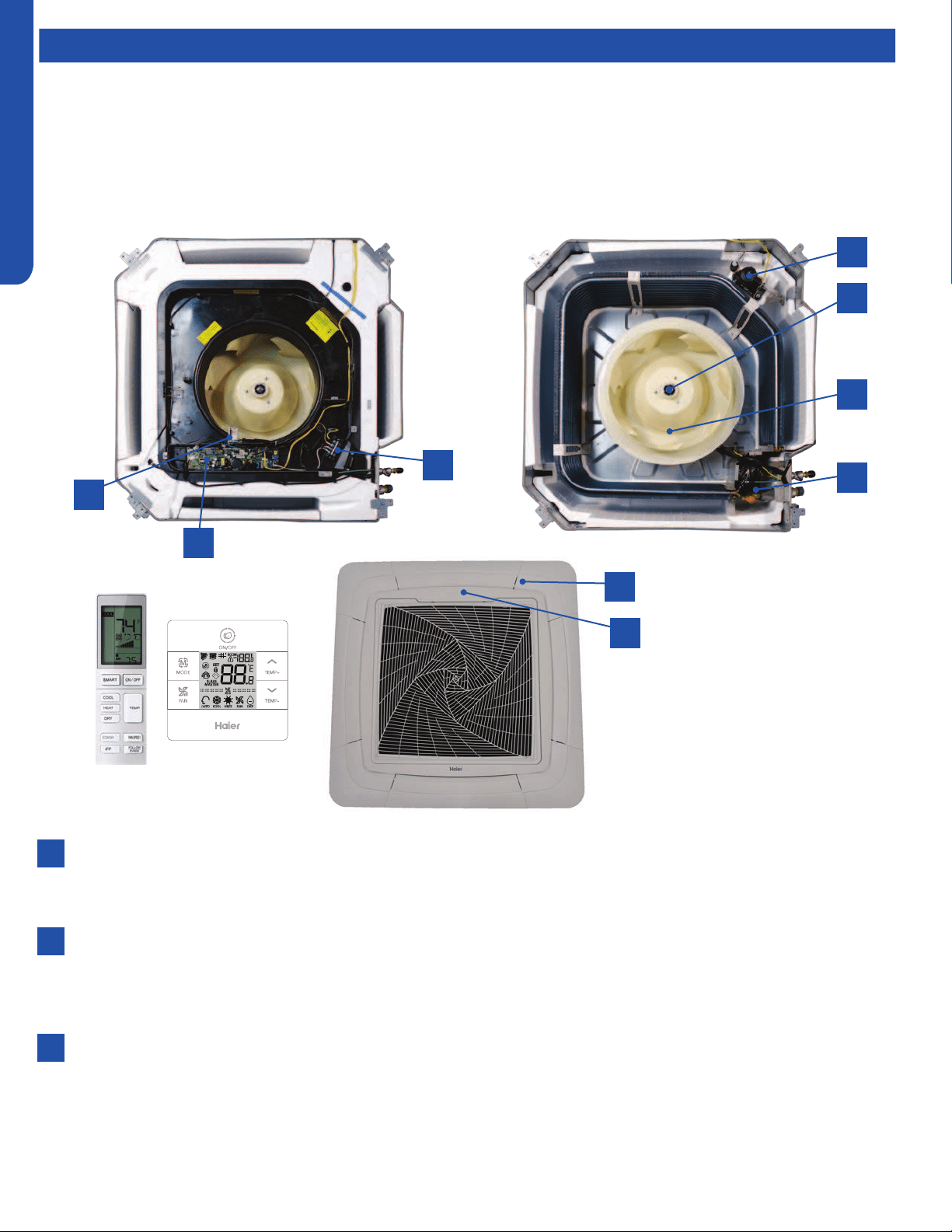
LARGE CASSETTE TECHNICAL OVERVIEW
E-2
ENGLISH
Components
The indoor cassette type units act as evaporator coils during cooling mode and condenser coils during heating mode. These
units have a built in condensate pump with an associated condensate level switch. The condensate pump is capable of lifting
water out of the indoor unit. If high water lift is needed, the water from the cassette pump should be pumped into a eld supplied
condensate pump with high lift power.
Cassette type indoor units can be operated with a wired controller or a remote control.
Component Overview
1
7
8
9
2
4
6
3
5
Terminal Block
Power to operate the indoor unit comes from the electrical line voltage terminal block at the outdoor unit. The wiring
includes 4 wires, 1, 2, 3 and ground. Wires 1 and 3 complete the data path. These wires should always be 14 gauge AWG
Stranded type wire. Splices in wires 1 or 3 may cause communication errors.
Motor Blower
The indoor unit features a multi speed blower motor that will change speed to match the capacity demand from the
outdoor unit. Separate motors located in the indoor unit control the operation of the motorized louvers. All of the louver
motors are controlled via commands received from the remote control. The blower motor is controlled by both the remote
control and by commands from the outdoor unit ECU.
Display
The indoor unit has a display that communicates system mode. The indoor unit does not display temperatures or
diagnostic codes. When a wired controller is used, this information is displayed on the wired controller. It is recommended
to use a wired controller with the cassette unit.
When servicing a diagnostic error, ALWAYS refer to the outdoor unit code to make diagnostic decisions.
1
2
3

LARGE CASSETTE TECHNICAL OVERVIEW
E-3
ENGLISH
Components
The Blower Assembly
The blower assembly consists of a plastic blower wheel that is connected to a PSC indoor blower motor. A set screw holds
the blower wheel to the blower motor.
The indoor blower motor is a Multi Speed Fan Motor that is connected to the indoor unit control board. The wiring from the
motor to indoor board consists of 4 wires connected to pins common, low , medium and high speeds.
During normal operation, the indoor control board will energize the indoor blower motor and request proper speed. The
motor has a run capacitor that is located in the Cassette unit’s control box. The run capacitor connects to the motor via
two orange wires. This capacitor is eld replaceable.
Louver Motors
The louver motors are stepper type motors that move the louvers up/down. The motors are controlled by pulsed voltage
that cannot be measured. If the louver does not move when it should, check for a bind in the louvers.
Piping Temperature Sensor
The Piping Temperature Sensor senses indoor coil temperature in the cooling mode and in the heating mode. This sensor is
used for Anti Freezing and Anti Cold Blow cycles. The sensor also provides critical temperature information to the ECU that
may be used in frequency adjustments.
Ambient Temperature Sensor
The Ambient Temperature Sensor senses room temperature. This sensor provides room temperature information to the
ECU for calculation of inverter capacity and temperature control.
Both sensors are negative temperature coecient type that reduce electrical resistance as temperature rises.
Control Board
The indoor unit circuit board controls the switching functions of the indoor unit. All control decisions are made by the
outdoor unit ECU. The indoor board has some limited diagnostic capability which will be covered in this manual.
Condensate Pump & Float Switch
4
5
6
7
8
9
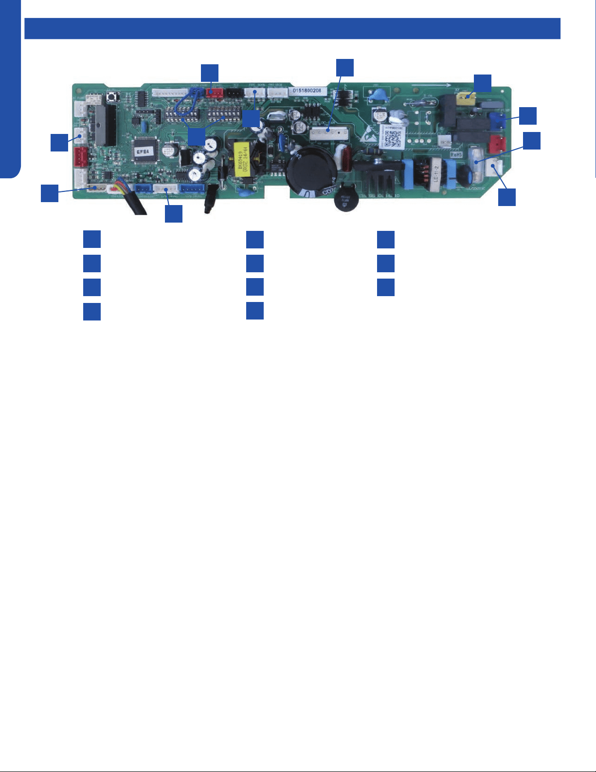
LARGE CASSETTE TECHNICAL OVERVIEW
E-4
ENGLISH
Components
Power
Communication Terminal
3.15A 250V Fuse
CN3 Pipe/Room Temp Sensors
1
4
2
5
3
7
10
8
6
9
CN19 Float Switch
CN11 Wired Remote
DIP Switches
CN36 Stepper Motor
11
CN6 Fan Motor
CN9 Condensate Pump
CN14 Panel Connection
Cassette Unit Indoor Circuit Board
1
3
2
10
11
9
6
7
5
4
8
The indoor unit circuit board controls the switching functions of
the indoor unit. All control decisions are made by the outdoor
unit ECU. The indoor board has some limited diagnostic
capability which will be covered in this manual.
The Indoor Unit Circuit Board communicates with the outdoor
unit ECU via a connection at Terminal Block screw 3. The
data pulse that sends the communication information can be
measured with a voltmeter placed to DCV range. From the
ground connection at the Terminal Block to the Number 3 screw
connection, the voltage should pulse up and down when data is
being transmitted.
This control board has control over the fan louver movement,
manual fan blower control, indoor coil temperature and indoor
air temperature sensing functions. All operational decisions are
controlled by the OUTDOOR UNIT ECU.
The connections on the indoor board are shown here in the
schematic drawing.
Line voltage to power the indoor unit comes in on Terminal
Block connections 1 and 2. Power connects from these terminal
connections to CH- 3 and CH-4 on the circuit board. If the
board does not respond to commands and has no display, check
for line voltage at these connections. When power is present at
the indoor board, the Display Power Indicator will be lit.
The control board has a replaceable 3.15A 250V fuse that
protects against excessive current. If power is present at
the board but the board does not work, check for continuity
through the fuse. Replace if the fuse is open.
The indoor unit temperature sensors are connected at
Plug CN-13. When testing the calibration of these sensors,
the wires can be released from the plug by pressing on the
tension tab on the side of the plug.
The receiver/display unit that is mounted to the front cover
of the indoor unit plugs into the circuit board via a connection
at Plug CN-29.
There is one motor that controls the movement of the
louvers. The motor connects to the circuit board at Plug CN-
14. The motor is located in the over of the louver assembly.
The blower/fan motor is connected to the circuit board at
plug CN-11.
The Cassette unit has a built in condensate pump. The pump
is connected to the circuit board on Plug CN-9. The pump is
energized whenever the Float Switch indicates that water
needs to be pumped from the cassette. The oat switch
connects onto the circuit board via Plug CN-18.
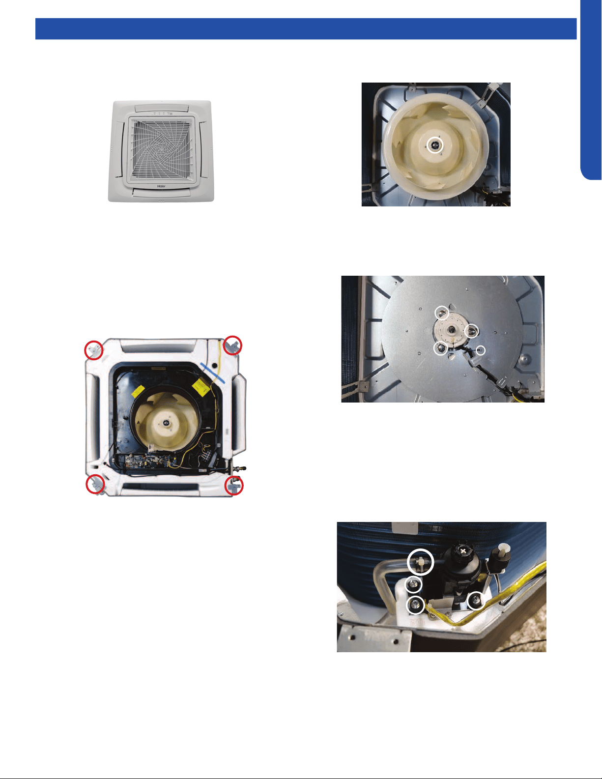
LARGE CASSETTE TECHNICAL OVERVIEW
E-5
ENGLISH
Testing
Accessing the Blower Motor and Condensate Pump
1. Disconnect power to the outdoor unit.
2. Remove the louver assembly.
Removing Fan Motor
1. Remove holding nut from fan blade.
Removing Condensate Pump
1. Remove screws holding condensate pump and oat switch
in position.
2. Disconnect condensate hose from condensate pump.
3. Remove assembly.
8. Remove screws holding the air inlet cover.
9. Drain the condensate water from the pan by removing
drain plug.
10. Remove the screws holding on the condensate pan
2. Fan blade will slide o motor shaft.
3. Remove Phillips head screw holding cover plate over motor
wiring leads.
4. Remove 3 nuts that hold fan motor in place.
5. Fan motor will come loose.
3. Disconnect the main power wire to the indoor unit.
4. Unplug the condensate pump and oat switch from wiring
harness.
5. Unplug fan motor from wiring harness.
6. Remove the oat switch, piping temperature sensor, fan
motor, and wired controller (if present) control board wire
connections . Disconnect plug to the coil sensor.
7. Remove screws holding the control box.
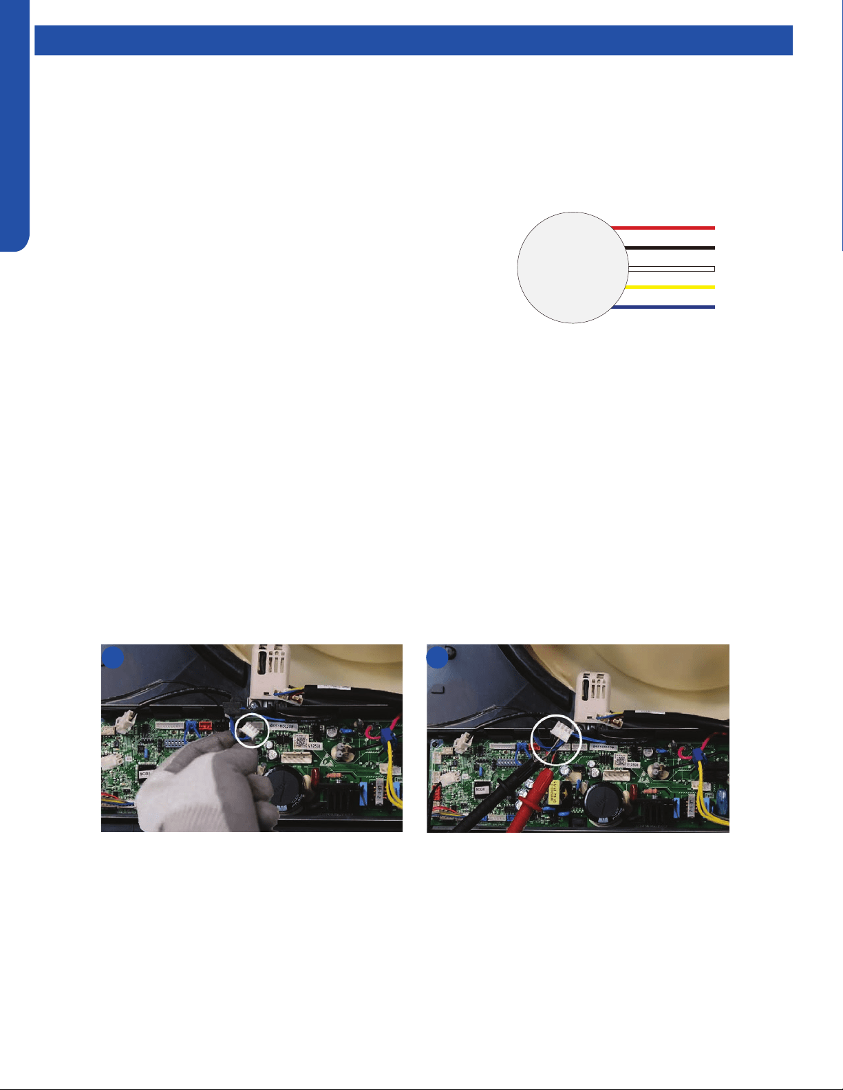
LARGE CASSETTE TECHNICAL OVERVIEW
E-6
ENGLISH
Testing
Indoor Fan Motor Test Procedure
If the indoor fan motor does not run:
1. Disconnect power to the system.
2. Remove the return air cover and access the circuit board fan motor connection.
3. Reset power and turn the remote control fan command to Fan On mode.
Testing Temperature Sensors
The easiest problems to solve will involve codes that are related to potential failure of temperature sensors. Common problems
may include loose connections, open electrically, and out of calibration. Checking the condition of the sensors requires a
temperature probe and an ohmmeter.
The Reference Section of this manual contains temperature resistance tables that can be used to check the calibration of the
sensors. The measured resistance must be within the tolerances printed on the top of the tables.
To test the electrical condition of a temperature sensor perform the following:
1. Conrm the sensor is rmly attached to the circuit board connection plug.
2. Remove the sensor wires form the connection plug by releasing holding tension on the plugs tension tab.
3. Use an ohmmeter to test the electrical resistance of the sensor.
4. Measure the air temperature near the sensor and compare the required resistance against measured resistance. (See chart in
reference section) If the sensor is within calibration, the sensor is good. If the sensor is out of calibration, replace the sensor.
(Tube Sensors should be removed from socket and exposed to air temperature during test.)
2 4
DC Motor
+310 VDC
DC Ground
+15 VDC
Signal
Feedback
Red
Black
White
Yellow
Blue
Motor Test:
1. If the motor doesn’t run, check for 310VDC between Pins 1 and 3. If it is
not present, the indoor board is bad. If voltage is present, continue on.
2. Check the voltage between Pins 3 and 4. The voltage should be +15VDC.
If it is not present, the board is bad. If voltage is present, continue on.
3. Check for voltage between Pins 3 and 6. If no DC voltage is present, the
board is bad. If voltage is present, change the motor.
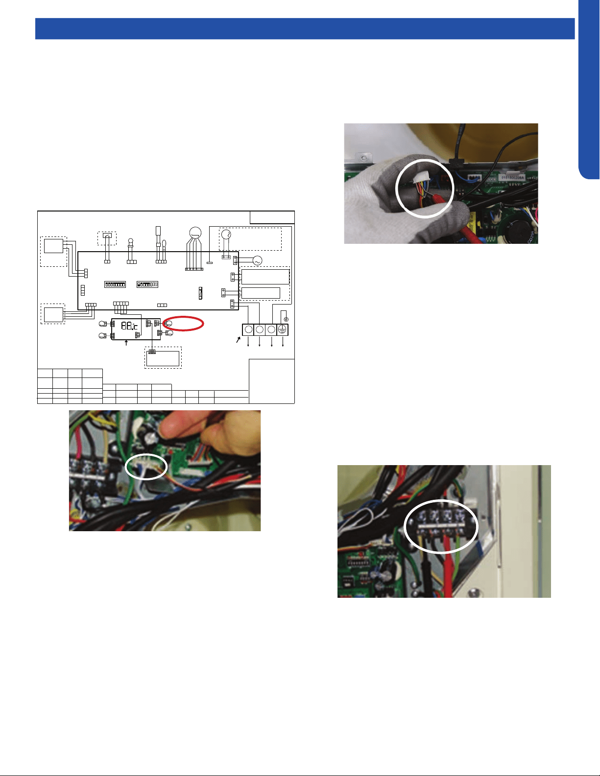
LARGE CASSETTE TECHNICAL OVERVIEW
E-7
ENGLISH
25
PCB Conguration
TO OUT DOOR UNIT
SW1-1
TYPE DEFINE
Cassette
Y/G:YELLOW/GREEN
RD:RED WHT:WHITE
BLK:BLACK
******************
.
SENSOR
CN1
CN11
CN19
SW3(BM3)
2
1
3
BLK
WHT
RD
NOTE:
1.DASHED PARTS ARE OPTIONAL.
2.USER SHOULD NOT CHANGE THE
DIP SWITCH SW1 SW3 WITHOUT GUIDENCE
3.SW3-5->SW3-8 ARE USED FOR WIRED CONTROLLER
ADRESS SELECT. SW3-1->SW3-4 ARE RESERVED.
CH1
OFF
OFF
TEMP
.
PIPING
DC FAN MOTOR
BA
C
87654321
SW1(BM1)
87654321
N
(SLIM)
Room card
available
ON
Y/G
0150516956U
L
I.R .RECEIVER
(WITH DIGITAL
DISPLAY)
WiFi
MODULE
.
B
A
C
WIRED
CONTROLLER
M
SENSOR
TEMP
.
ROOM
ROOM CARD
CN3
CN6
T5A 250VAC
CN16
DRAIN
PUMP
M
CN9
CN10
CN4
CN14
FUSE
FLOAT
SWITCH
CN13
CN4
CN3
CN2
CN7
CN1
CN6
INTELLIGENT
MOVE EYE DEVICE
M
M
LOUVER
STEP MOTOR4
LOUVER
STEP MOTOR3
M
M
LOUVER STEP
MOTOR2
LOUVER STEP
MOTOR1
INDOOR UNIT
MAIN CONTROL
BOARD
I.R .RECEIVER :
INFRARED REMOTE
RECEIVER .
TEMP.:TEMPERATURE
ON
OFF
ON
CN26
A
B
M
FRESH AIR MOTOR /
EXTERNAL ALARM OUTPUT
(FUNCTION IN FUTURE )
( Contact rating_230VAC,3A)
CAPACITY
(BTU/H)
SW1-2
SW1-3
OFF ON
ON
ON
ON
ON
SW1-4
unavailable
OFF
ON
SW1-5
COOL HEAT
COOL ONLY
HEAT PUMP
SW1-6
SW1-7
SW1-8
OFF
OFF
INDOOR UNIT
TERMINAL BLOCK
CN8
24000
ON
ON
OFF
ELECTRIC HEATING TERMINAL
RATING_230VAC,3A
CONNECT TO THIRD PARTY RELAY
CN15
ELECTRIC HEATING
THERMOSTAT / FUSE
OFF
36000
42000
48000
ON
ON
ON
Testing
Testing Louver Motors
If the louver does not operate with command from the remote
control, either the indoor board is bad, or the louver motor
is defective. It is more likely the motor is defective than the
board. (Make sure the louver assembly is not binding and
keeping the vanes from moving.)
1. Remove power from the unit and remove the indoor unit
cover.
2. Access the circuit board.
3. Identify the inoperable louver motor on the schematic
drawing below and disconnect the plug from the circuit
board.
4. Use an Ohmmeter to test the electrical continuity of the
louver motor windings. The proper resistance for each
winding can be found in this table. If the motor winding
resistance is erratic or shows open, the motor is defective.
Replace the motor.
5. If the motor checks out good, replace the indoor control
board.
Testing Communication Circuit
If an Error E7 occurs, perform the following test to determine
if the indoor control board is functioning properly to send data
to the outdoor unit.
Perform this test with the unit powered and all wiring
connected between indoor and outdoor unit.
Make sure all wiring between the indoor and outdoor unit
are correct. There should no splices between the indoor and
outdoor unit wiring connecting terminals 1 or 3. Make sure
wiring is correct, before performing this test.
1. Measure the DC voltage between terminals 1 and 3 on the
indoor terminal block.
2. The voltage should uctuate between 8VDC and 23VDC.
The uctuating signal indicates a good communication
path.
3. If the voltage does not uctuate, and the wiring is good,
the indoor board is defective.
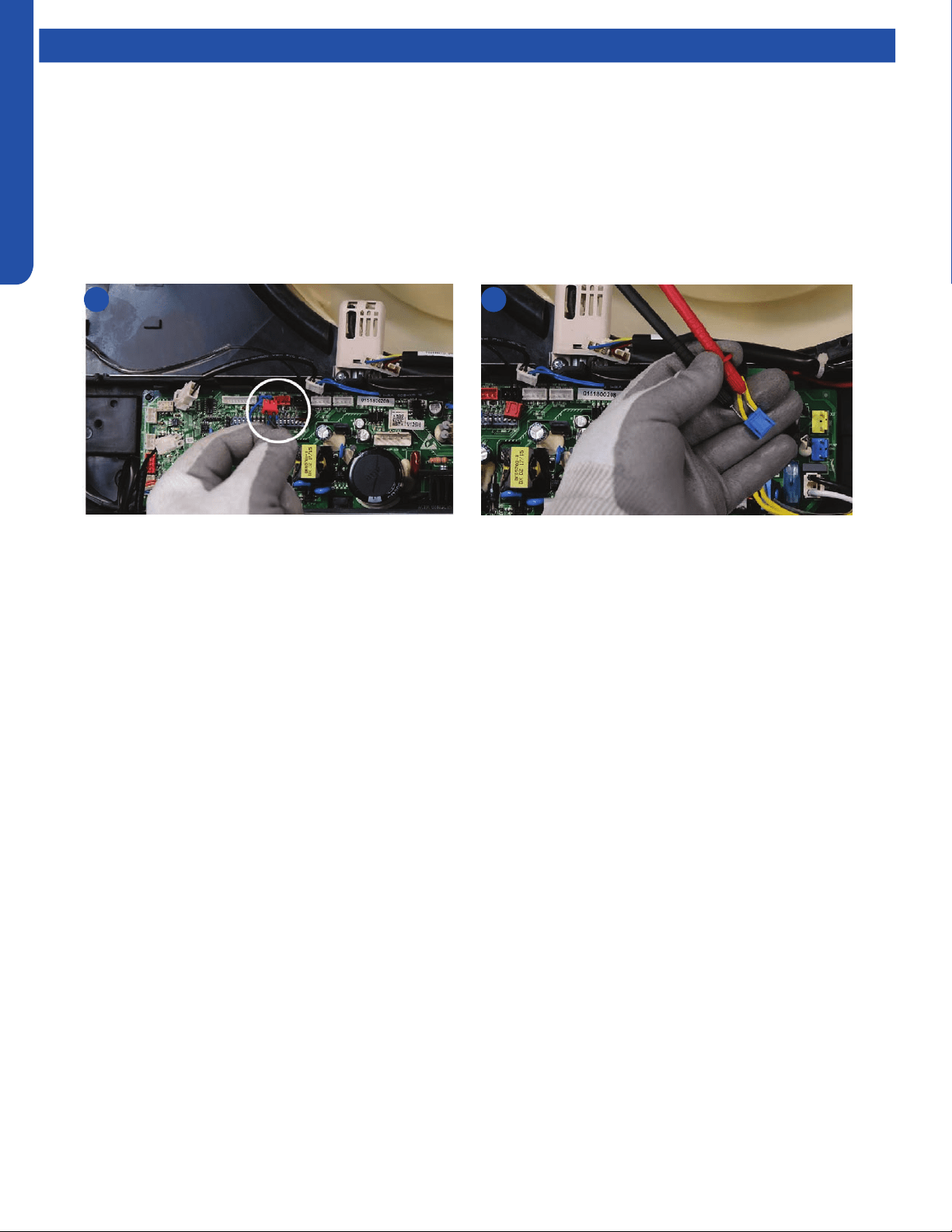
LARGE CASSETTE TECHNICAL OVERVIEW
E-8
ENGLISH
Testing
Test Condensate Pump and Float Switch
If the internal condensate pump does not operate, the pump may be bad or the oat switch may be defective. Perform the
following test:
1. Access the electrical control box.
2. Unplug the oat switch from the circuit board.
3. The pump should start.
4. If the pump does not start, check for voltage at the pump connector on the board. There should be 230 Volts AC to the pump.
If there is not, the circuit board is defective. If there is proper voltage to the pump, either the pump or associated pump wiring
is defective.
2 4
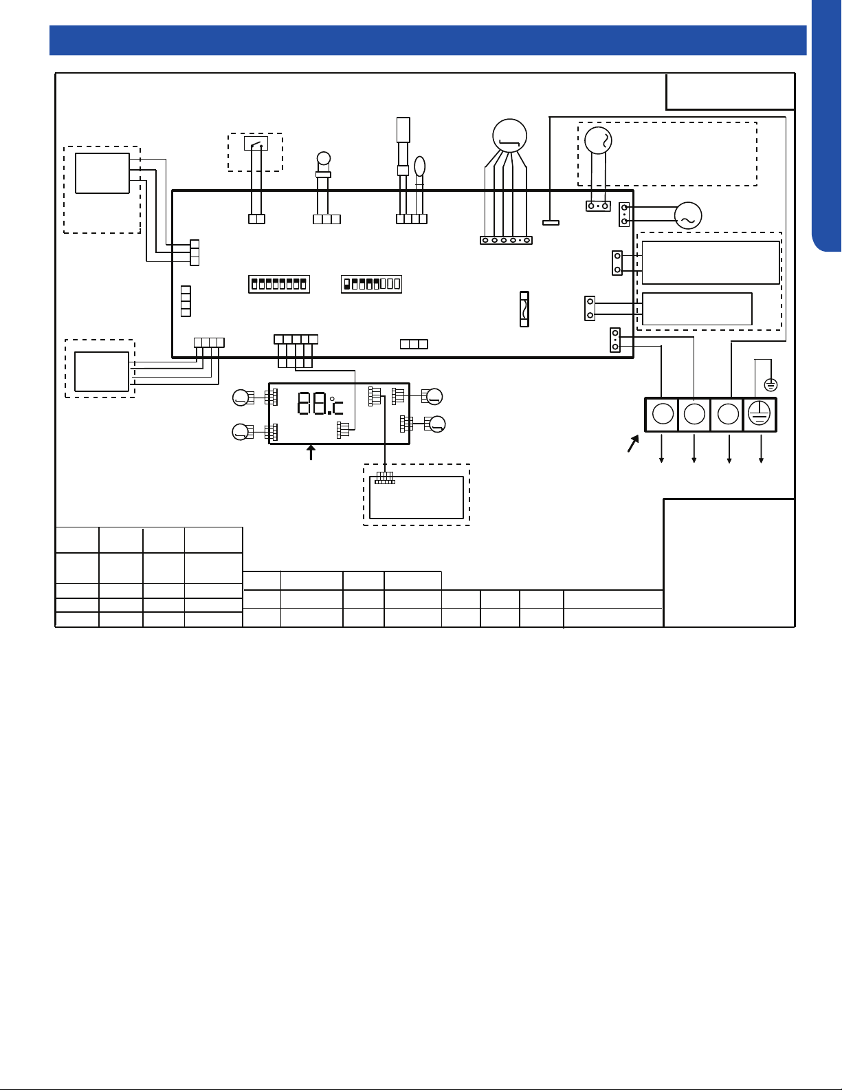
LARGE CASSETTE TECHNICAL OVERVIEW
E-9
ENGLISH
Wiring Diagram
25
PCB Conguration
TO OUT DOOR UNIT
SW1-1
TYPE DEFINE
Cassette
Y/G:YELLOW/GREEN
RD:RED WHT:WHITE
BLK:BLACK
******************
.
SENSOR
CN1
CN11
CN19
SW3(BM3)
2
1
3
BLK
WHT
RD
NOTE:
1.DASHED PARTS ARE OPTIONAL.
2.USER SHOULD NOT CHANGE THE
DIP SWITCH SW1 SW3 WITHOUT GUIDENCE
3.SW3-5->SW3-8 ARE USED FOR WIRED CONTROLLER
ADRESS SELECT. SW3-1->SW3-4 ARE RESERVED.
CH1
OFF
OFF
TEMP
.
PIPING
DC FAN MOTOR
BA
C
87654321
SW1(BM1)
87654321
N
(SLIM)
Room card
available
ON
Y/G
0150516956U
L
I.R .RECEIVER
(WITH DIGITAL
DISPLAY)
WiFi
MODULE
.
B
A
C
WIRED
CONTROLLER
M
SENSOR
TEMP
.
ROOM
ROOM CARD
CN3
CN6
T5A 250VAC
CN16
DRAIN
PUMP
M
CN9
CN10
CN4
CN14
FUSE
FLOAT
SWITCH
CN13
CN4
CN3
CN2
CN7
CN1
CN6
INTELLIGENT
MOVE EYE DEVICE
M
M
LOUVER
STEP MOTOR4
LOUVER
STEP MOTOR3
M
M
LOUVER STEP
MOTOR2
LOUVER STEP
MOTOR1
INDOOR UNIT
MAIN CONTROL
BOARD
I.R .RECEIVER :
INFRARED REMOTE
RECEIVER .
TEMP.:TEMPERATURE
ON
OFF
ON
CN26
A
B
M
FRESH AIR MOTOR /
EXTERNAL ALARM OUTPUT
(FUNCTION IN FUTURE )
( Contact rating_230VAC,3A)
CAPACITY
(BTU/H)
SW1-2
SW1-3
OFF ON
ON
ON
ON
ON
SW1-4
unavailable
OFF
ON
SW1-5
COOL HEAT
COOL ONLY
HEAT PUMP
SW1-6
SW1-7
SW1-8
OFF
OFF
INDOOR UNIT
TERMINAL BLOCK
CN8
24000
ON
ON
OFF
ELECTRIC HEATING TERMINAL
RATING_230VAC,3A
CONNECT TO THIRD PARTY RELAY
CN15
ELECTRIC HEATING
THERMOSTAT / FUSE
OFF
36000
42000
48000
ON
ON
ON
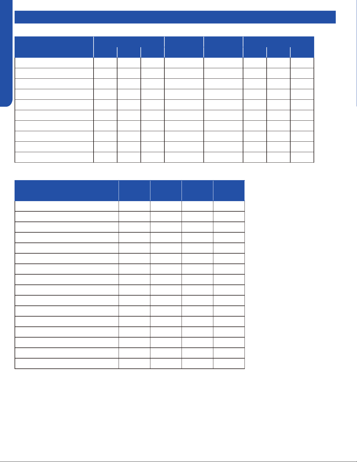
LARGE CASSETTE TECHNICAL OVERVIEW
E-10
ENGLISH
Topic TitleDIP Switch Settings
Description
Capacity Room Card Running Mode Unit Type
SW1-1 SW1-2 SW1-3 SW1-4 SW1-5 SW1-6 SW1-7 SW1-8
Capacity: 24kBTU(7.1kW) ON ON OFF --- --- --- --- ---
Capacity: 30kBTU(9.0kW) OFF OFF ON --- --- --- --- ---
Capacity: 35kBTU(10.5kW) ON OFF ON --- --- --- --- ---
Capacity: 42kBTU(12.5kW) OFF ON ON --- --- --- --- ---
Capacity: 48kBTU(14.0kW_ ON ON ON --- --- --- --- ---
Room card invalid(default) --- --- --- OFF --- --- --- ---
Room card valid --- --- --- ON --- --- --- ---
Heat pump(default) --- --- --- --- OFF --- --- ---
Cooling only --- --- --- --- ON --- --- ---
High performance cassette --- --- --- --- --- OFF OFF ON
Indoor unit Address
(Indoor unit address for one wired
controller control more than one unit)
BM3-5 BM3-6 BM3-7 BM3-8
0 (master) OFF OFF OFF OFF
1 (slave) OFF OFF OFF ON
2 (slave) OFF OFF ON OFF
3 (slave) OFF OFF ON ON
4 (slave) OFF ON OFF OFF
5 (slave) OFF ON OFF ON
6 (slave) OFF ON ON OFF
7 (slave) OFF ON ON ON
8 (slave) ON OFF OFF OFF
9 (slave) ON OFF OFF ON
10 (slave) ON OFF ON OFF
11 (slave) ON OFF ON ON
12 (slave) ON ON OFF OFF
13 (slave) ON ON OFF ON
14 (slave) ON ON ON OFF
15 (slave) ON ON ON ON
BM1 DIP Switch Settings
Wired Controller Communication Address
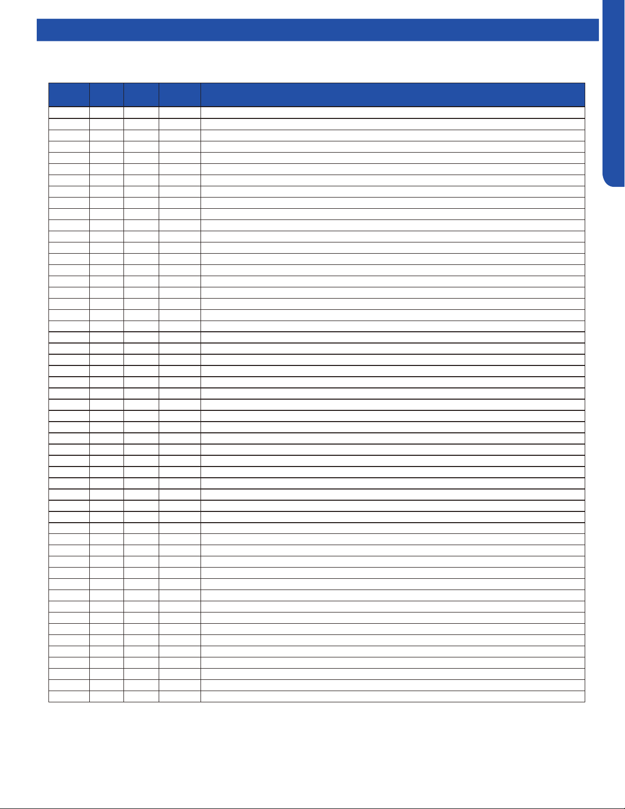
LARGE CASSETTE TECHNICAL OVERVIEW
E-11
ENGLISH
Topic TitleError Codes
The error codes that are displayed on the indoor units may vary from the outdoor unit codes. The information communicated by
the error code will be the SAME for both indoor and outdoor units even though the numbers may dier.
Indoor
LED4
Indoor
LED1
Panel
Display
Outdoor
LED
Diagnosis
2 1 15 1 Outdoor EEPROM failure
2 2 16 2 IPM overcurrent or short circuit
2 3 17 / Compressor over current during deceleration
2 4 18 4 Communication failure between the IPM and outdoor PCB
2 5 19 5 Module operated overload (compressor overload protection)
2 6 1A 6 Module low or high voltage
2 7 1B / Compressor current sampling circuit fault
2 8 1C 8 Overheat protection for discharge temperature
2 9 1D 9 Malfunction of the DC fan motor
3 0 1E 10 Malfunction of defrost temperature sensor
3 1 1F 11 Suction temperature sensor failure
3 2 20 12 Ambient temperature sensor failure
3 3 21 13 Discharge temperature sensor failure
3 4 22 / PFC circuit loop voltage
3 5 23 15 Communication failure between the indoor & outdoor unit
3 6 24 16 Lack of refrigerant or discharging
3 7 25 17 4-way valve switching failure
3 8 26 18 Loss of synchronism detection
3 9 27 / Low DC or AC voltage
4 0 28 20 Indoor thermal overload
4 1 29 21 Indoor coil frosted
4 2 2A / PFC circuit loop overcurrent
4 3 2B 23 Module thermal overload
4 4 2C 24 Compressor start failure, over-current
4 5 2D 25 Phase current protection (IPM)
4 6 2E 26 MCU reset
4 7 2F 27 Module current detect circuit malfunction
4 8 30 28 Liquid pipe sensor failure: Circuit A
4 9 31 29 Liquid pipe sensor failure: Circuit B
5 0 32 30 Liquid pipe sensor failure: Circuit C
5 1 33 31 Liquid pipe sensor failure: Circuit D
5 2 34 32 Gas pipe sensor failure: Circuit A
5 3 35 33 Gas pipe sensor failure: Circuit B
5 4 36 34 Gas pipe sensor failure: Circuit C
5 5 37 35 Gas pipe sensor failure: Circuit D
5 6 38 36 Gas pipe sensor failure: Circuit E
5 7 39 / Compressor overcurrent detected by IPM
5 8 3A 38 Malfunction of module temperature sensor momentary power failure detection
5 9 3B 39 Malfunction of condensing temperature sensor
6 0 3C 40 Liquid pipe sensor failure: Circuit E
6 1 3D 41 Toci temperature sensor failure
6 2 3E 42 High Pressure switch open
6 3 3F 43 Low Pressure switch open
6 4 40 44 System high pressure protection: Overcharged, high condensing temperature or malfunction of fan motor
6 5 41 45 System low pressure protection: Undercharged, low defrosting temperature, or malfunction of fan motor
0 1 01 / Indoor ambient temperature sensor failure
0 2 02 / Indoor coil temperature sensor failure
0 4 04 / Indoor PCB EEPROM failure
0 7 07 / Communication fault between the indoor and outdoor unit
0 8 08 / Communication fault between the controller and Indoor unit
0 12 0C / Drain system malfunction
0 13 0D / Zero cross signal detected wrong
0 14 0E / Indoor fan motor malfunction

[This page intentionally left blank.]
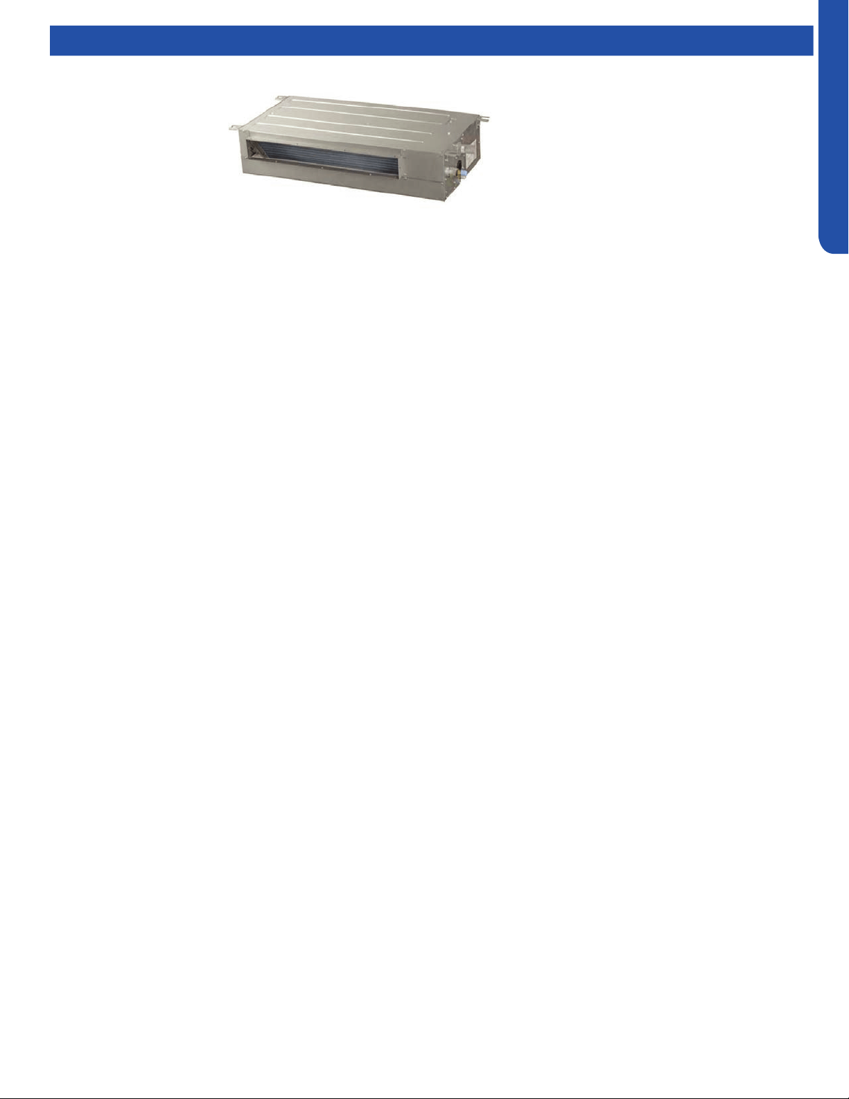
SLIM DUCT TECHNICAL OVERVIEW
F-1
ENGLISH
SLIM DUCT TECHNICAL OVERVIEW
Table of Contents
Components ..........................................................................................................................................................................F-2
Component Overview ..........................................................................................................................................................F-2
Indoor Unit Circuit Board ......................................................................................................................................................F-3
Ductwork /Grilles ...................................................................................................................................................................F-5
Testing ................................................................................................................................................................................... F-6
Test Condensate Pump and Float Switch ............................................................................................................................F-6
Testing Communication Circuit ...........................................................................................................................................F-6
Testing Temperature Sensors ..............................................................................................................................................F-7
Indoor Fan Motor Voltage Check .........................................................................................................................................F-7
Wiring Diagram & DIP Switch Settings ...................................................................................................................................F-8
Error Codes ............................................................................................................................................................................F- 9
AD07SL2VHB
AD09SL2VHB
AD12SL2VHB
AD18SL2VHB

SLIM DUCT TECHNICAL OVERVIEW
F-2
ENGLISH
Components
The Slim Duct Indoor Unit will act as evaporator coils during cooling mode and condenser coils during heating mode. This unit can
operate with a motorized supply air louver or it can have a LIMITED amount of ducting added to the unit’s return and supply air
duct connection anges. The return air ducting can be connected to the end of the cabinet or the bottom blank o plate can be
removed for bottom return conguration.
DIP Switches on the unit’s circuit board congure the fan power to match the ducting conguration.
These units have a built in condensate pump with an associated condensate level switch. The condensate pump is capable of
lifting water out of the indoor unit. If high water lift is needed, the water from the cassette pump should be pumped into a eld
supplied condensate pump with high lift power.
The layout of the system is very straightforward and components are easily accessed should service be required. The blower
assembly and room air temperature sensor is accessed at the rear of the evaporator coil, and the piping temperature sensor
is located under the top cover. The condensate pump and oat switch are accessed under the removable panel next to the
electrical control box.
The wired controller can be congured to sense room air temperature. There is no option for use with remote control.
All operating status and information is displayed on the wired controller. The Slim Duct unit does not have a display.
Slim Duct units are
controlled by a wired
controller only.
8
8
6
4
4
2
2
7
5
5
3
3
1
1
Evaporator Coil
Blower Assembly
The indoor unit features a DC variable speed dual shaft
blower motor that will change speed to match the
capacity demand from the outdoor unit. The motor
is a dual shaft type that powers two individual blower
assemblies.
The blower assembly consists of 2 plastic blowers. A set
screw holds each blower wheel to the blower motor.
The indoor blower motor is connected to the indoor
unit control board. The wiring from the motor to indoor
board consists of 5 wires connected to pins that deliver
line voltage, speed, and feedback information.
During normal operation, the indoor control board will
energize the indoor blower motor and request proper
speed. Fan power should be set using the DIP Switches
SW1 settings.
Terminal Block
Power to operate the indoor unit comes from the
electrical line voltage terminal block at the outdoor unit.
The wiring includes 4 wires, 1, 2, 3 and ground. Wires 1
and 3 complete the data path. These wires should always
be 14 gauge AWG Stranded type wire. Splices in wires 1
or 3 may cause communication errors.
Control Board
Located under the electrical control box cover.
Ambient Temperature Sensor
The Ambient Temperature Sensor senses room
temperature. This sensor provides room temperature
information to the ECU for calculation of inverter
capacity and temperature control.
Component Overview
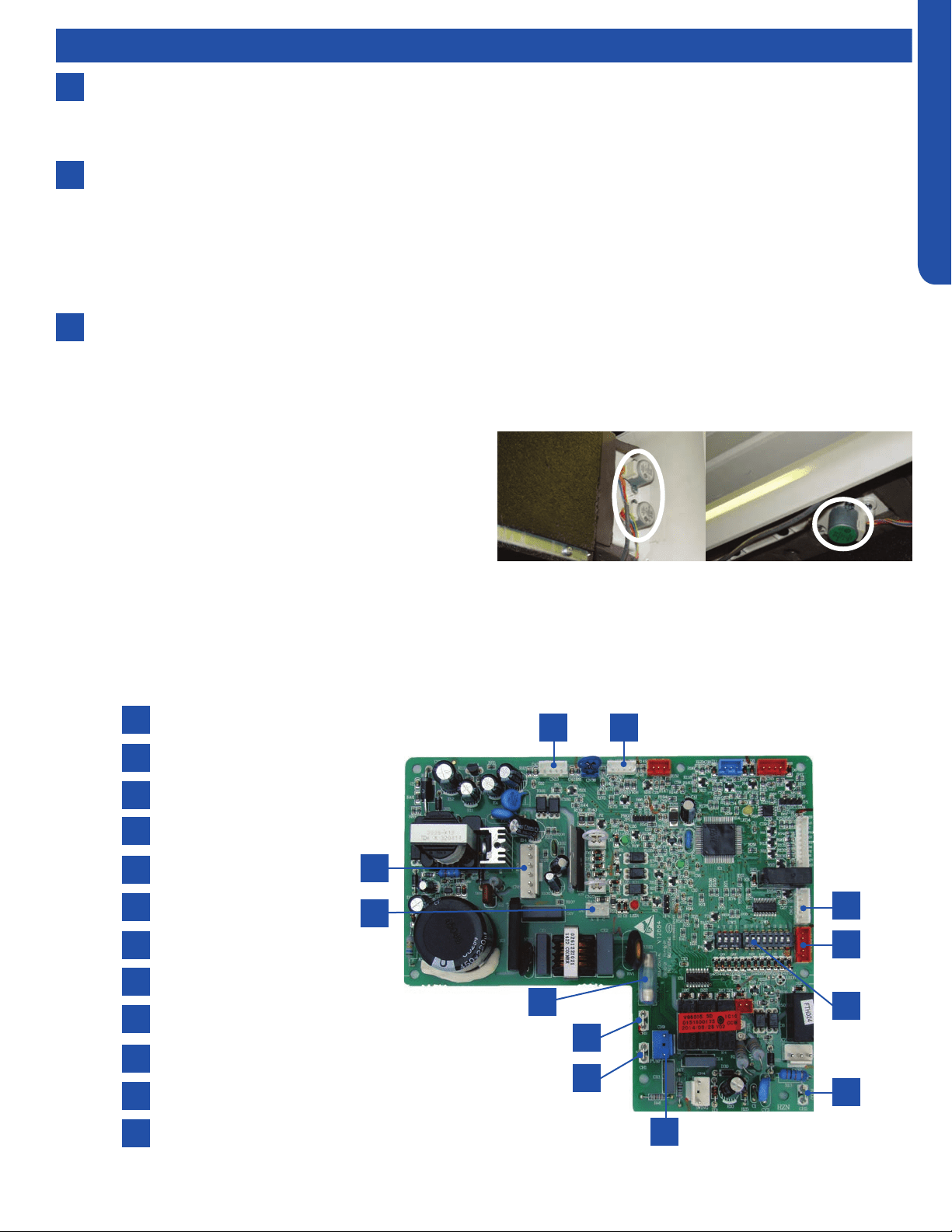
SLIM DUCT TECHNICAL OVERVIEW
F-3
ENGLISH
Components
Accessory Louver Motors (not shown)
Separate motors located in the accessory supply air louver
control the operation of the motorized louvers. The louver
motors are stepper type motors that move the louvers up/
down. The motors are controlled by pulsed voltage that cannot
be measured. If the louver does not move when it should, check
for a bind in the louvers.
All of the louver motors are controlled via commands received
from the remote control.
8
6
7
Piping Temperature Sensor
The Piping Temperature Sensor senses indoor coil temperature in the cooling mode and in the heating mode. This sensor is
used for Anti Freezing and Anti Cold Blow cycles. The sensor also provides critical temperature information to the ECU that
may be used in frequency adjustments.
Condensate Pump
The Slim Duct unit has a built in condensate pump. The pump is connected to the circuit board. The pump is energized
whenever the Float Switch indicates that water needs to be pumped from the cassette. The oat switch connects onto the
circuit board.
The oat switch and pump are located behind the removable insulated cover next to the electrical control box. The pump
is hermetically sealed and requires no maintenance. The oat switch is a normally closed switch, that opens as water rises.
The oat switch requires no maintenance.
Gravity Drain Ports
The indoor unit has the option for either gravity drain systems or the use of an internal condensate pump with oat switch.
The pump is capable of minimal lift. If high lift is required, the water from the Slim Duct unit should be pumped to a eld
supplied condensate pump that is capable of high lift.
Indoor Unit Circuit Board
The indoor unit circuit board controls the switching functions of the indoor unit. All control decisions are made by the outdoor
unit ECU. The indoor board has some limited diagnostic capability which will be covered in this manual.
1
4
7
10
2
5
8
11
3
6
9
12
L Terminal
N Terminal
Communication Terminal
5A 250V Fuse
CN13 Sensors
CN18 Float Switch
CN1 Wired Remote
DIP Switches
CN14 Stepper Motor
CN15 Stepper Motor
CN6 Fan Motor
CN9 Condensate Pump
1
4
7
10
2
5
8
11
3
6
9
12
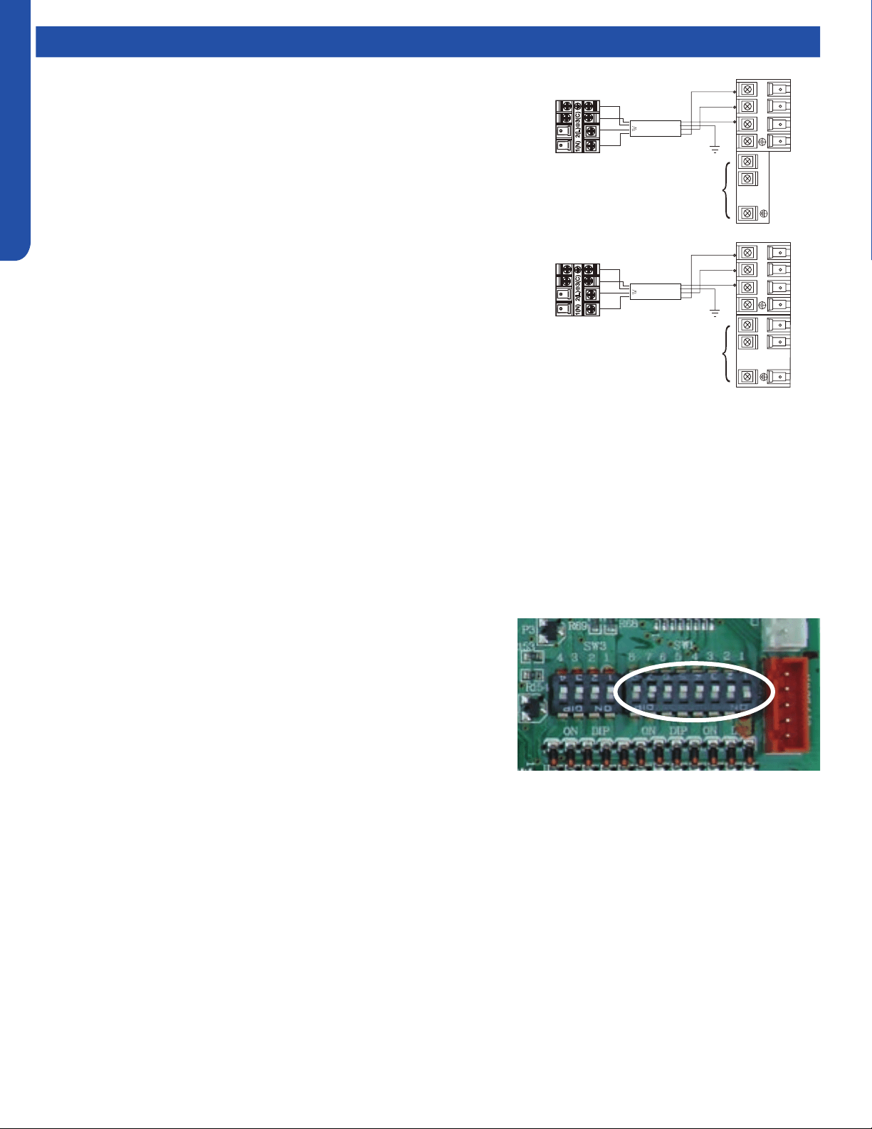
SLIM DUCT TECHNICAL OVERVIEW
F-4
ENGLISH
This control board has control over the fan louver movement, manual fan blower control, indoor coil temperature and indoor air
temperature sensing functions. All operational decisions are controlled by the OUTDOOR UNIT ECU.
The control board has a replaceable 5A 250V fuse that protects against excessive current. If power is present at the board but the
board does not work, check for continuity through the fuse. Replace if the fuse is open.
The indoor unit temperature sensors are connected at Plug CN-13. When testing the calibration of these sensors, the wires can
be released from the plug by pressing on the tension tab on the side of the plug.
There 3 motors that control the directional movement of the accessory louver. The motor connects to the circuit board at Plug
CN-14, CN-15 and CN-16. The motors are located in the louver assembly.
The blower motor is connected to the circuit board at plug CN-6.
SW1 DIP Switches
There are two sets of DIP switches on the Circuit Board. SW3 is for factory
use only. SW1 is used to set the conguration of the indoor unit operation.
The rst three switches SW1-1, SW1-2 and SW1-3 select the indoor unit
capacity.
Air Delivery Power is set with DIP Switches SW1-4 and SW1-5. The settings
are shown in Hydrostatic Selection of 0Pa, up to 30Pa. SW1-7 and SW1-8
dene the unit type. The conversions are as follows:
0Pa=0”w.c.
10Pa= .04”w.c.
20Pa=.08”w.c.
30Pa=.12”w.c.
• Recommended settings are for motorized Louver set to 10Pa.
• Ducting limited to a total of .12”w.c. External Static set to 30Pa.
Components
The Indoor Unit Circuit Board communicates with the outdoor unit ECU
via a connection at Terminal Block screw 3. The data pulse that sends the
communication information can be measured with a voltmeter placed to DCV
range. From the ground connection at the Terminal Block to the Number 3
screw connection, the voltage should pulse up and down when data is being
transmitted.
Line voltage to power the indoor unit comes in on Terminal Block connections 1
and 2. Power connects from these terminal connections to CH- 1 and CH-2 on
the circuit board. If the board does not respond to commands and has no display,
check for line voltage at these connections. When power is present at the indoor
board, the wired controller will be energized.
The connections on the indoor board are shown here in the schematic drawing.
Outdoor unit
3
2
Power
Wiring
1
)
(
N
)
(L
)
(
C
3
2
1
)
(
N
)
(
L
)
(
C
Indoor uni
t
3wire 14AWG
Control Wiring
Outdoor unit
3
2
Power
Wiring
1
)
(
N
)
(L
)
(
C
2
1
)
(
N
)
(
L
Indoor uni
t
3wire 14AWG
Control Wiring
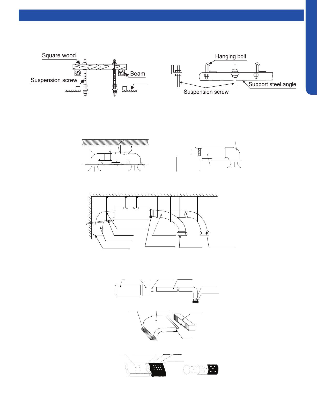
SLIM DUCT TECHNICAL OVERVIEW
F-5
ENGLISH
Topic TitleDuctwork / Grilles
Ductwork Installation
Use rivet to connect the
air return duct on the air
return inlet of the indoor
unit, then connect the
other end with the air
return
Indoor unit
Soft
connection
or static
box
Transition
duct
Rounded
duct
Tie-in of air
distribution
Air distribution
Air return blind Air return duct
Indoor unit
Rivet
gluey nail
heat
preservation cotton
tinfoil
gluey nail cap
adhesive tape
Roof Installation
Ceiling
Air supply
Unit
Return air
Return air box
Roof
Air outlet grill
Air supply
Unit
Return air box
Return air
Long Duct
Suspending hook
Drain pipe
Air return duct
Air return blind
Air out duct
Transition duct
Tie-in of air
Distribution
Air distribution
Basic Duct Congurations
Here are the typical duct congurations that can be used with the unit.

SLIM DUCT TECHNICAL OVERVIEW
F-6
ENGLISH
Topic TitleTesting
If the internal condensate pump does not operate, the pump
may be bad or the oat switch may be defective. Perform the
following test:
1. Access the electrical control box.
2. Unplug the oat switch from the circuit board.
Test Condensate Pump and Float Switch
The unit has a built-in condensate pump and water level
safety switch. There are also two optional ports for gravity
drainage. The condensate pump is rated to lift water up to 27
9/16” from the point of discharge.
The unit comes with a grey connection hose with clamp. This
hose is connected to the High ESP Duct unit condensate
discharge hose port. The other end of the hose is sized to
accept 3/4 inch PVC piping.
Recommended condensate piping congurations are shown
here:
3. The pump should start.
4. If the pump does not start, check for voltage at the control
board pump connection. There should be 230 Volts AC to
the pump. If there is not, the circuit board is defective. If
there is proper voltage to the pump, either the pump or
associated pump wiring is defective.
Testing Communication Circuit
If an Error E7 occurs, perform the following test to determine
if the indoor control board is functioning properly to send data
to the outdoor unit.
Perform this test with the unit powered and all wiring
connected between indoor and outdoor unit.
Make sure all wiring between the indoor and outdoor unit
are correct. There should no splices between the indoor and
outdoor unit wiring connecting terminals 1 or 3. Make sure
wiring is correct, before performing this test.
1. Measure the DC voltage between terminals 1 and 3 on the
indoor terminal block.
2. The voltage should uctuate between 8VDC and 23VDC.
The uctuating signal indicates a good communication
path.
3. If the voltage does not uctuate, and the wiring is good,
the indoor board is defective.

SLIM DUCT TECHNICAL OVERVIEW
F-7
ENGLISH
Topic TitleTesting
Testing Temperature Sensors
The easiest problems to solve will involve codes that are
related to potential failure of temperature sensors. Common
problems may include loose connections, open electrically,
and out of calibration. Checking the condition of the sensors
requires a temperature probe and an ohmmeter.
The Reference Section of this manual contains temperature
resistance tables that can be used to check the calibration
of the sensors. The measured resistance must be within the
tolerances printed on the top of the tables.
1. Conrm the sensor is rmly attached to the circuit board
connection plug.
2. Remove the sensor wires from the connection plug by
releasing holding tension on the plugs tension tab.
3. Use an ohmmeter to test the electrical resistance of the
sensor.
4. Measure the air temperature near the sensor and compare
the required resistance against measured resistance.
(refer to charts in reference section) If the sensor is
within calibration, the sensor is good. If the sensor is out
of calibration, replace the sensor. (Tube Sensors should
be removed from socket and exposed to air temperature
during test.)
If The Indoor Fan Motor Does Not Run:
1. Remove the front cover and access the fan motor circuit
board connection.
2. Reset power and turn the remote control fan command to
Fan On mode.
Motor Test:
1. If the motor doesn’t run, check for 310VDC between Pins 1
and 3. If it is not present, the indoor board is bad. If voltage
is present, continue on.
2. Check the voltage between Pins 3 and 4. The voltage
should be +15VDC. If it is not present, the board is bad. If
voltage is present, continue on.
3. Check for voltage between Pins 3 and 6. If no DC voltage is
present, the board is bad. If voltage is present, change the
motor.
Indoor Fan Motor Voltage Check
1
2
3
DC Motor
+310 VDC
DC Ground
+15 VDC
Signal
Feedback
Red
Black
White
Yellow
Blue
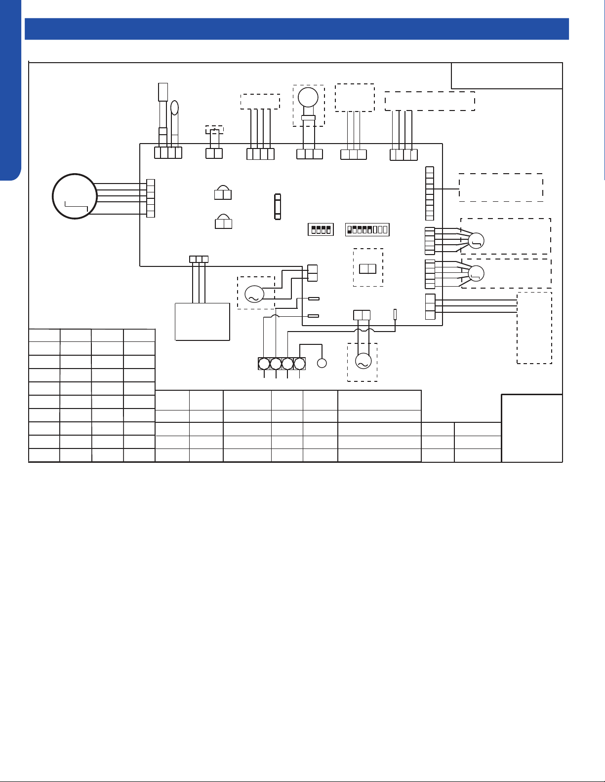
SLIM DUCT TECHNICAL OVERVIEW
F-8
ENGLISH
Topic TitleWiring Diagrams & DIP Switch Settings
0150515412
SW1-7 SW1-8
Type define
OFF OFF Silm duct
OFF ON
Convertible
ON OFF Middle pressure duct
ON ON
Slim duct (America)
SW1-3
BTU
B: BLACK
R: RED
W: WHITE
Y/G: YELLOW /
GREEN
OFF OFF OFF
ON OFF OFF
OFF ON OFF
ON ON OFF
OFF OFF ON
ON OFF ON
OFF ON ON
ON ON ON
60000
9000
12000
48000
18000
24000
28000
36000
NOTE:
1.DASHED PARTS ARE
OPTIONAL.
2.
USER SHOULD NOT TO SET
SW1 AND SW2 WITHOUT GUIDANCE.
3.THE BRIDGE (CN22 CN23) ON SLAVE
UNITS PCB SHOULD BE CUT OFF WHEN
ONE WIRED CONTROLLER CONTROL MORE
THAN ONE UNIT.
OFF
OFF
SW1-4
SW1-5
SW1-6
OFF
OFF
OFF
ON
TEMP.
SENSOR
ROOM
SENSOR
PIPING TEMP.
ROOMCARD
CN13
CN19
CN14
CH3
CN29
ROTOMNAFCD
CN36
CN7
CN18
CN5
CN6
CN15
CN37
CN4
CH1
CH2
CN9
CN1
SW1
SW2
T5A/250VAC
FUSE
WIRED
CONTROLLER
RECEIVER
FLOAT
SWITCH
U-HOME
REMOTE
CENTRAL
PANNEL CONTROLLER
LEFT/RIGHT
SWING MOTOR
ALARM
OR AIR EXCHAGE
LINKAGE
SWING
CN8
HEAT
CN22
CN23
PUMP
TO OUT DOOR
2
1
3
B
W
R
Y/G
ON
ON
ON
ON
20 Pa
40 Pa
0 Pa
10 Pa
Room card
M
87654321
4321
ON
ON
UP/DOWN
SWING MOTOR
REMOTE
M
M
M
BA
C
BA
C
M
available
SW1-2SW1-1
unavailable
G
G
ON OFF
OFF
7000
Hydrostatic
selection
SLIM DUCT TECHNICAL OVERVIEW
F-9
ENGLISH
Topic TitleError Codes
The error codes that are displayed on the indoor units may vary from the outdoor unit codes. The information communicated by
the error code will be the SAME for both indoor and outdoor units even though the numbers may dier.
Indoor
LED4
Indoor
LED3
Outdoor
LED
Diagnosis
2 1 1 Outdoor EEPROM failure
2 2 2 IPM overcurrent or short circuit
2 3 / Compressor over current during deceleration
2 4 4 Communication failure between the IPM and outdoor PCB
2 5 5 Module operated overload (compressor overload protection)
2 6 6 Module low or high voltage
2 7 / Compressor current sampling circuit fault
2 8 8 Overheat protection for discharge temperature
2 9 9 Malfunction of the DC fan motor
3 0 10 Malfunction of defrost temperature sensor
3 1 11 Suction temperature sensor failure
3 2 12 Ambient temperature sensor failure
3 3 13 Discharge temperature sensor failure
3 4 / PFC circuit loop voltage
3 5 15 Communication failure between the indoor & outdoor unit
3 6 16 Lack of refrigerant or discharging
3 7 17 4-way valve switching failure
3 8 18 Loss of synchronism detection
3 9 / Low DC or AC voltage
4 0 20 Indoor thermal overload
4 1 21 Indoor coil frosted
4 2 / PFC circuit loop overcurrent
4 3 23 Module thermal overload
4 4 24 Compressor start failure, over-current
4 5 25 Phase current protection (IPM)
4 6 26 MCU reset
4 7 27 Module current detect circuit malfunction
4 8 28 Liquid pipe sensor failure: Circuit A
4 9 29 Liquid pipe sensor failure: Circuit B
5 0 30 Liquid pipe sensor failure: Circuit C
5 1 31 Liquid pipe sensor failure: Circuit D
5 2 32 Gas pipe sensor failure: Circuit A
5 3 33 Gas pipe sensor failure: Circuit B
5 4 34 Gas pipe sensor failure: Circuit C
5 5 35 Gas pipe sensor failure: Circuit D
5 6 36 Gas pipe sensor failure: Circuit E
5 7 / Compressor overcurrent detected by IPM
5 8 38 Malfunction of module temperature sensor momentary power failure detection
5 9 39 Malfunction of condensing temperature sensor
6 0 40 Liquid pipe sensor failure: Circuit E
6 1 41 Toci temperature sensor failure
6 2 42 High Pressure switch open
6 3 43 Low Pressure switch open
6 4 44 System high pressure protection: Overcharged, high condensing temperature or malfunction of fan motor
6 5 45 System low pressure protection: Undercharged, low defrosting temperature, or malfunction of fan motor
0 1 / Indoor ambient temperature sensor failure
0 2 / Indoor coil temperature sensor failure
0 4 / Indoor PCB EEPROM failure
0 7 / Communication fault between the indoor and outdoor unit
0 8 / Communication fault between the controller and Indoor unit
0 17 / DC voltage of the fan motor driver too high or too low
0 18 / Fan motor driver over 95°F (35°C)
0 19 / Indoor fan motor out of step
0 12 / Drain system malfunction
0 13 / Zero cross signal detected wrong
0 14 / Indoor fan motor malfunction
0 15 / Indoor fan motor overcurrent

[This page intentionally left blank.]
MID-STATIC DUCTED TECHNICAL OVERVIEW
G-1
ENGLISH
MID-STATIC DUCTED TECHNICAL OVERVIEW
Table of Contents
Components ......................................................................................................................................................................... G-2
Component Overview ......................................................................................................................................................... G-2
Indoor Unit Circuit Board .....................................................................................................................................................G-4
Fresh Air Function ................................................................................................................................................................ G-5
Ductwork /Grilles .................................................................................................................................................................. G-6
Testing .................................................................................................................................................................................. G-7
Test Condensate Pump and Associated Float Switch .......................................................................................................G-7
Testing Temperature Sensors .............................................................................................................................................G-7
Testing Communication Circuit ..........................................................................................................................................G-8
Indoor Fan Motor Voltage Check ........................................................................................................................................ G-8
Static Pressure Charts .........................................................................................................................................................G-9
Board Replacement ...........................................................................................................................................................G-10
Removing the Condensate Pump .....................................................................................................................................G-10
Removing Fan Motor .........................................................................................................................................................G-10
Replacing WiFi Module .......................................................................................................................................................G-11
Wiring Diagram ................................................................................................................................................................... G-12
DIP Switch Settings ............................................................................................................................................................G-13
Error Codes .........................................................................................................................................................................G-14
USYM09UCDSA
USYM12UCDSA
USYM18UCDSA
USYM24UCDSA
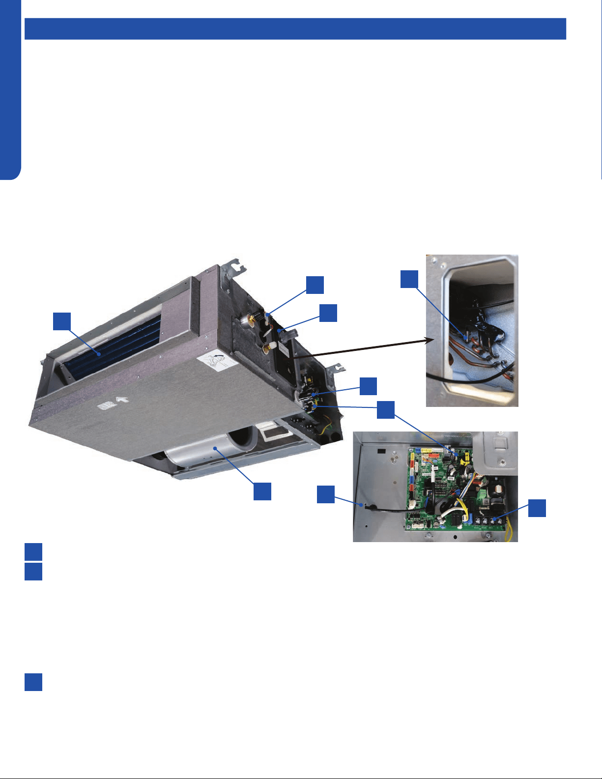
MID-STATIC DUCTED TECHNICAL OVERVIEW
G-2
ENGLISH
ComponentsComponents
The Mid-Static Ducted Indoor Unit will act as evaporator coils during cooling mode and condenser coils during heating mode.
This unit can operate with a motorized supply air louver or it can have a LIMITED amount of ducting added to the unit’s return
and supply air duct connection anges. The return air ducting can be connected to the end of the cabinet or the bottom blank o
plate can be removed for bottom return conguration.
DIP Switches on the unit’s circuit board congure the fan power to match the ducting conguration.
These units have a built in condensate pump with an associated condensate level switch. The condensate pump is capable of
lifting water out of the indoor unit. If high water lift is needed, the water from the cassette pump should be pumped into a eld
supplied condensate pump with high lift power.
The layout of the system is very straightforward and components are easily accessed should service be required. The blower
assembly and room air temperature sensor is accessed at the rear of the evaporator coil, and the piping temperature sensor
is located under the top cover. The condensate pump and oat switch are accessed under the removable panel next to the
electrical control box.
The wired controller can be congured to sense room air temperature. There is no option for use with remote control.
All operating status and information is displayed on the wired controller. The Mid-Static Ducted unit does not have a display.
8
9
6
4
2
2
7
5
3
3
1
1
Evaporator Coil
Blower Assembly
The indoor unit features a DC variable speed dual shaft blower motor that will change speed to match the capacity demand
from the outdoor unit. The motor is a dual shaft type that powers two individual blower assemblies.
The blower assembly consists of 2 plastic blowers. A set screw holds each blower wheel to the blower motor.
The indoor blower motor is connected to the indoor unit control board. The wiring from the motor to indoor board consists
of 5 wires connected to pins that deliver line voltage, speed, and feedback information.
During normal operation, the indoor control board will energize the indoor blower motor and request proper speed. Fan
power should be set using the DIP Switches SW1 settings.
Terminal Block
Power to operate the indoor unit comes from the electrical line voltage terminal block at the outdoor unit. The wiring
includes 4 wires, 1, 2, 3 and ground. Wires 1 and 3 complete the data path. These wires should always be 14 gauge AWG
Stranded type wire. Splices in wires 1 or 3 may cause communication errors.
Component Overview

MID-STATIC DUCTED TECHNICAL OVERVIEW
G-3
ENGLISH
ComponentsComponents
8
6
4
7
5
Control Board
Located under the electrical control box cover.
Ambient Temperature Sensor
The Ambient Temperature Sensor senses room temperature. This sensor provides room temperature information to the
ECU for calculation of inverter capacity and temperature control.
Piping Temperature Sensor
The Piping Temperature Sensor senses indoor coil temperature in the cooling mode and in the heating mode. This sensor is
used for Anti Freezing and Anti Cold Blow cycles. The sensor also provides critical temperature information to the ECU that
may be used in frequency adjustments.
Condensate Pump
The Mid-Static Ducted unit has a built in condensate pump. The pump is connected to the circuit board. The pump is
energized whenever the Float Switch indicates that water needs to be pumped from the cassette. The oat switch
connects onto the circuit board.
The oat switch and pump are located behind the removable insulated cover next to the electrical control box. The pump
is hermetically sealed and requires no maintenance. The oat switch is a normally closed switch, that opens as water rises.
The oat switch requires no maintenance.
Gravity Drain Ports
The indoor unit has the option for either gravity drain systems or the use of an internal condensate pump with oat switch.
The pump is capable of minimal lift. If high lift is required, the water from the Mid-Static Ducted unit should be pumped to a
eld supplied condensate pump that is capable of high lift.
WiFi
The unit comes shipped with a WiFi module that provides control via a smartphone app.
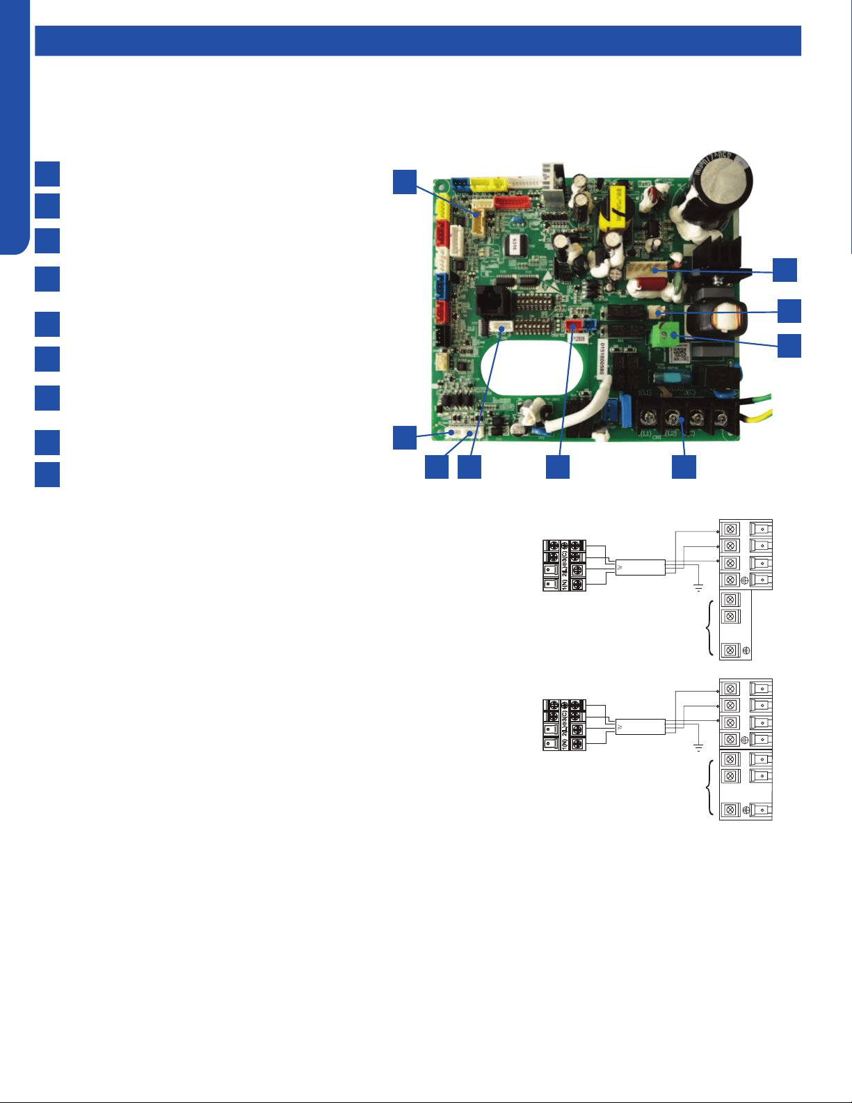
MID-STATIC DUCTED TECHNICAL OVERVIEW
G-4
ENGLISH
Components
This control board has control over the fan louver movement, manual fan blower control, indoor coil temperature and indoor air
temperature sensing functions. All operational decisions are controlled by the OUTDOOR UNIT ECU.
The control board has a replaceable 5A 250V fuse that protects against excessive current. If power is present at the board but
the board does not work, check for continuity through the fuse. Replace if the fuse is open.
The indoor unit temperature sensors are connected at Plug CN-13. When testing the calibration of these sensors, the wires can
be released from the plug by pressing on the tension tab on the side of the plug.
There 3 motors that control the directional movement of the accessory louver. The motor connects to the circuit board at Plug
CN-14, CN-15 and CN-16. The motors are located in the louver assembly.
The blower motor is connected to the circuit board at plug CN-6.
The Indoor Unit Circuit Board communicates with the outdoor unit ECU
via a connection at Terminal Block screw 3. The data pulse that sends the
communication information can be measured with a voltmeter placed to DCV
range. From the ground connection at the Terminal Block to the Number 3
screw connection, the voltage should pulse up and down when data is being
transmitted.
Line voltage to power the indoor unit comes in on Terminal Block connections
1 and 2. Power connects from these terminal connections to CH- 1 and CH-2 on
the circuit board. If the board does not respond to commands and has no display,
check for line voltage at these connections. When power is present at the indoor
board, the wired controller will be energized.
The connections on the indoor board are shown here in the schematic drawing.
Outdoor unit
3
2
Power
Wiring
1
)
(
N
)
(L
)
(
C
3
2
1
)
(
N
)
(
L
)
(
C
Indoor uni
t
3wire 14AWG
Control Wiring
Outdoor unit
3
2
Power
Wiring
1
)
(
N
)
(L
)
(
C
2
1
)
(
N
)
(
L
Indoor uni
t
3wire 14AWG
Control Wiring
Indoor Unit Circuit Board
The indoor unit circuit board controls the switching functions of the indoor unit. All control decisions are made by the outdoor
unit ECU. The indoor board has some limited diagnostic capability which will be covered in this manual.
9
8
7
6
1
2
3
4
5
CN17-GEA3 wi module socket
CN6-DC fan motor socket
CN10-Fresh air link/E.A.O socket
CN-4-Frelay for auxiliary heater link (Dry contact,rating-
230VAC ,3A)
CN1- Power terminal block
CN19-Float switch socket
CN3-Temperature sensor socket (Tr:ROOM SENSOR,
Tp:PIPE SENSOR)
CN22-1-Wired controller socket2
CN22-Wired controller socket1
6 578
2
1
9
3
4

MID-STATIC DUCTED TECHNICAL OVERVIEW
G-5
ENGLISH
Topic TitleComponents
Fresh Air Function
When there is fresh air signal received by the Indoor Unit PCB
(the fresh air signal can be sent by infrared remote controller
or wired controller), the Normal fresh air function is valid.
When a call for Fresh Air is received, via the wireless or wired
controller, the unit will enable the standard fresh air function.
This function can be activated at any mode except defrost
mode. When the IDU been turned o by controller, the fresh
air function is invalid. This function can be activated in any
mode, except for defrost mode. When the Indoor Unit has
been turned o via the controller, the fresh air function will be
disabled.
Call for Fresh Air is Received:
In Cooling / Dehumidication mode:
The fresh air output will maintain a 20 minutes ON, 20 minutes
OFF cycle after the compressor starts.
This cycle will be active until one of the following occurs:
• Fresh air function is canceled via the controller (wired
controller or wireless remote controller)
• Indoor unit has been via the controller
• The compressor stops.
In Fan Only mode:
The fresh air output will maintain a 20 minutes ON, 20 minutes
OFF cycle
This cycle will be active until one of the following occurs:
• Fresh air function is canceled via the controller (wired
controller or wireless remote controller)
• Indoor unit has been via the controller
In Heating mode
The fresh air output will maintain a 20 minutes ON, 20 minutes
OFF cycle after the compressor starts.
This cycle will be active until one of the following occurs:
• Fresh air function is canceled via the controller (wired
controller or wireless remote controller)
• Indoor unit has been via the controller
• The compressor stops.
• The system enters into Defrost Cycle.
Special Fresh Air Function (Canadian Ventilation Mode - Mid
Static Ducted Only)
Special fresh air function (Canadian ventilation mode) is valid
when DIP switch SW3_1 is set to the ON position, and invalid
when DIP switch SW3_1 is set to OFF position.
When this function is enabled and the Indoor Unit is ON,
the the unit will proceed Continuous Fresh Air, keeping
the Indoor Fan Motor energized even if the compressor is
stopped or the IDU reaches it’s real setpoint temperature (real
setpoint=customer set point + compensation point).
Notes:
• During an active Call, the fan motor speed will be whatever
setting the customer has set it to. Once the Call is satised,
the fan motor speed will be set to a special Low setting that
corresponds to the ESP setting.
• During a Defrost Cycle, the indoor fan is disabled, along with
the Fresh Air Function

MID-STATIC DUCTED TECHNICAL OVERVIEW
G-6
ENGLISH
Ductwork / Grilles
Ductwork Installation
Use rivet to connect the
air return duct on the air
return inlet of the indoor
unit, then connect the
other end with the air
return
Indoor unit
Soft
connection
or static
box
Transition
duct
Rounded
duct
Tie-in of air
distribution
Air distribution
Air return blind Air return duct
Indoor unit
Rivet
gluey nail
heat
preservation cotton
tinfoil
gluey nail cap
adhesive tape
Roof Installation
Ceiling
Air supply
Unit
Return air
Return air box
Roof
Air outlet grill
Air supply
Unit
Return air box
Return air
Long Duct
Suspending hook
Drain pipe
Air return duct
Air return blind
Air out duct
Transition duct
Tie-in of air
Distribution
Air distribution
Basic Duct Congurations
Here are the typical duct congurations that can be used with the unit.
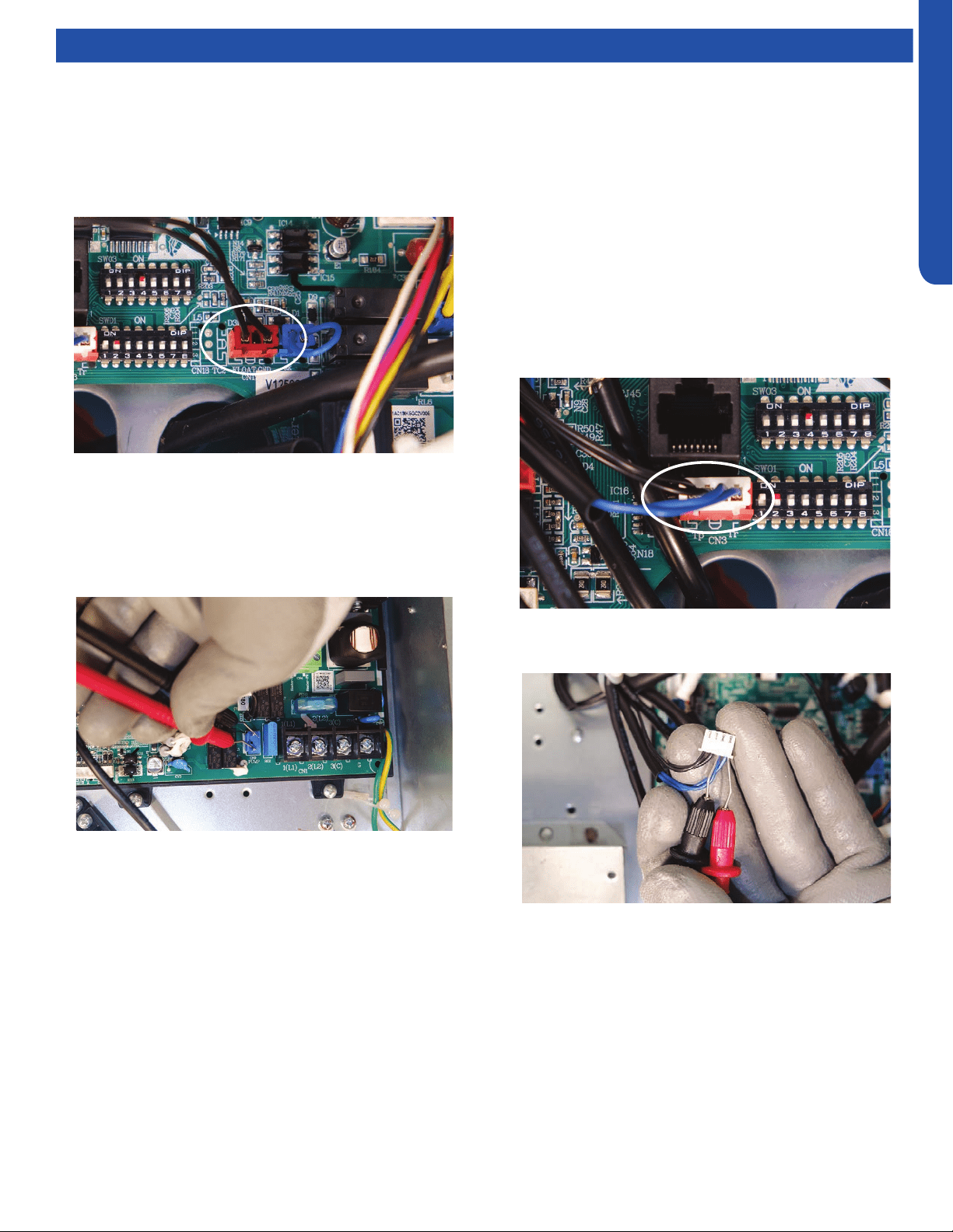
MID-STATIC DUCTED TECHNICAL OVERVIEW
G-7
ENGLISH
Testing
Testing Temperature Sensors
The easiest problems to solve will involve codes that are
related to potential failure of temperature sensors. Common
problems may include loose connections, open electrically,
and out of calibration. Checking the condition of the sensors
requires a temperature probe and an ohmmeter.
The Reference Section of this manual contains temperature
resistance tables that can be used to check the calibration
of the sensors. The measured resistance must be within the
tolerances printed on the top of the tables.
1. Conrm the sensor is rmly attached to the circuit board
connection plug.
2. Remove the sensor wires from the connection plug by
releasing holding tension on the plugs tension tab.
Test Condensate Pump and Associated Float Switch
If the internal condensate pump does not operate, the pump
may be bad or the oat switch may be defective. Perform the
following test:
1. Access the electrical control box.
2. Unplug the oat switch from the circuit board.
3. The pump should start.
4. If the pump does not start, check for voltage at the pump
control board connection. There should be 230 Volts AC
to the pump. If there is not, the circuit board is defective.
If there is proper voltage to the pump, either the pump or
associated pump wiring is defective.
3. Use an ohmmeter to test the electrical resistance of the
sensor.
4. Measure the air temperature near the sensor and compare
the required resistance against measured resistance.
(refer to charts in reference section) If the sensor is
within calibration, the sensor is good. If the sensor is out
of calibration, replace the sensor. (Tube Sensors should
be removed from socket and exposed to air temperature
during test.)
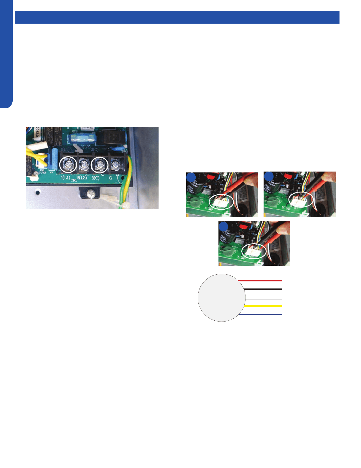
MID-STATIC DUCTED TECHNICAL OVERVIEW
G-8
ENGLISH
Testing
Testing Communication Circuit
If an Error E7 occurs, perform the following test to determine
if the indoor control board is functioning properly to send data
to the outdoor unit.
Perform this test with the unit powered and all wiring
connected between indoor and outdoor unit.
Make sure all wiring between the indoor and outdoor unit
are correct. There should no splices between the indoor and
outdoor unit wiring connecting terminals 1 or 3. Make sure
wiring is correct, before performing this test.
1. Measure the DC voltage between terminals 1 and 3 on the
indoor terminal block.
2. The voltage should uctuate between 8VDC and 23VDC.
The uctuating signal indicates a good communication
path.
3. If the voltage does not uctuate, and the wiring is good,
the indoor board is defective.
If The Indoor Fan Motor Does Not Run:
1. Remove the front cover and access the fan motor circuit
board connection.
2. Reset power and turn the remote control fan command to
Fan On mode.
Motor Test:
1. If the motor doesn’t run, check for 310VDC between Pins 1
and 3. If it is not present, the indoor board is bad. If voltage
is present, continue on.
2. Check the voltage between Pins 3 and 4. The voltage
should be +15VDC. If it is not present, the board is bad. If
voltage is present, continue on.
3. Check for voltage between Pins 3 and 6. If no DC voltage is
present, the board is bad. If voltage is present, change the
motor.
Indoor Fan Motor Voltage Check
1
2
3
DC Motor
+310 VDC
DC Ground
+15 VDC
Signal
Feedback
Red
Black
White
Yellow
Blue
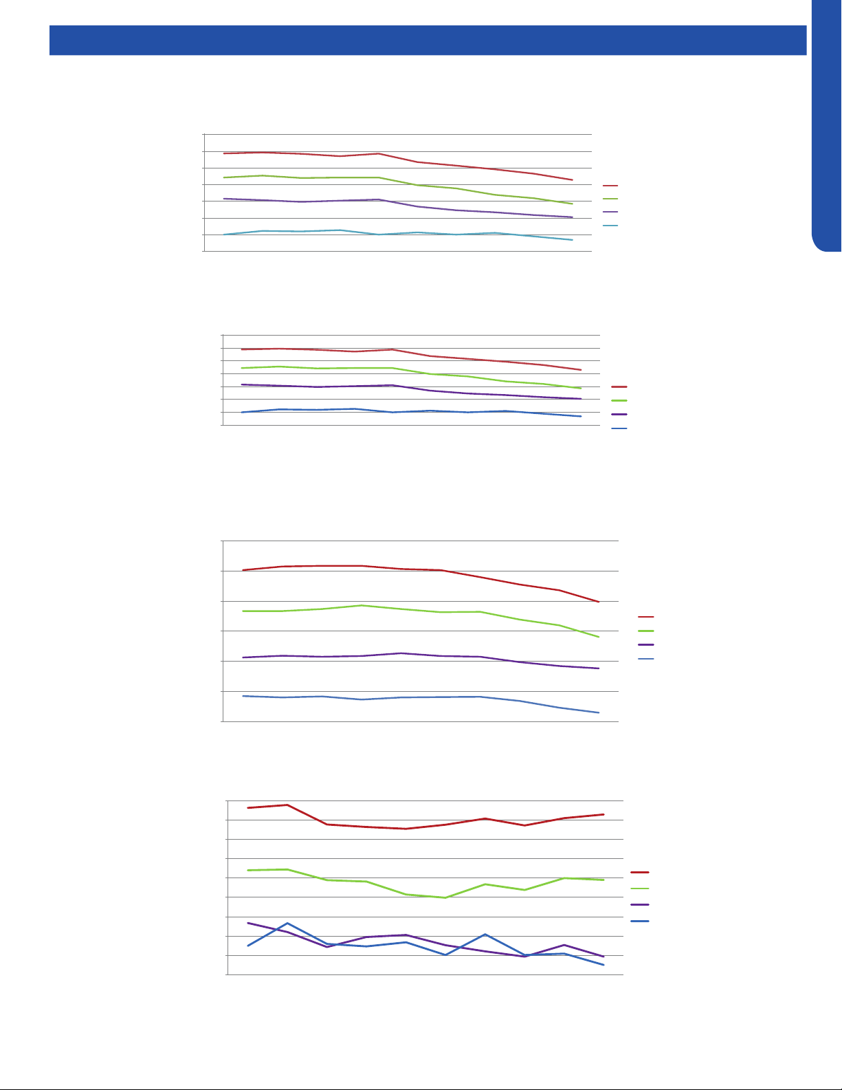
MID-STATIC DUCTED TECHNICAL OVERVIEW
G-9
ENGLISH
Testing
Static Pressure Charts
Air ow and static pressure curves
205
255
305
355
405
455
505
555
0.1 0.15 0.2 0.28 0.36 0.4 0.44 0.48 0.52 0.6
Static pressure (in.wc.)
AM09SL2VHA air flow and static pressure chart
High(cfm)
Med(cfm)
Low(cfm)
Quiet(cfm)
(
USYM09UCDSA
Air ow and static pressure curves
205.0
255.0
305.0
355.0
405.0
455.0
505.0
555.0
External
static
pressure
(in. wc.)
0.10 0.15 0.20 0.28 0.36 0.40 0.44 0.48 0.52
Air flow cfm
Static pressure (in.wc.)
High(cfm)
Med(cfm)
Low(cfm)
Quiet(cfm)
USYM12UCDSA
350.0
400.0
450.0
500.0
550.0
600.0
650.0
0.10 0.15 0.20 0.28 0.36 0.40 0.44 0.48 0.52 0.60
Air flow cfm
Static pressure (in.wc.)
High(cfm)
Med(cfm)
Low(cfm)
Quiet(cfm)
USYM18UCDSA
400.0
450.0
500.0
550.0
600.0
650.0
700.0
750.0
800.0
850.0
0.10 0.15 0.20 0.28 0.36 0.40 0.44 0.48 0.52 0.60
Air flow cfm
Static pressure (in.wc.)
High m3/h
Med m3/h
Low m3/h
Quiet m3/h
USYM24UCDSA
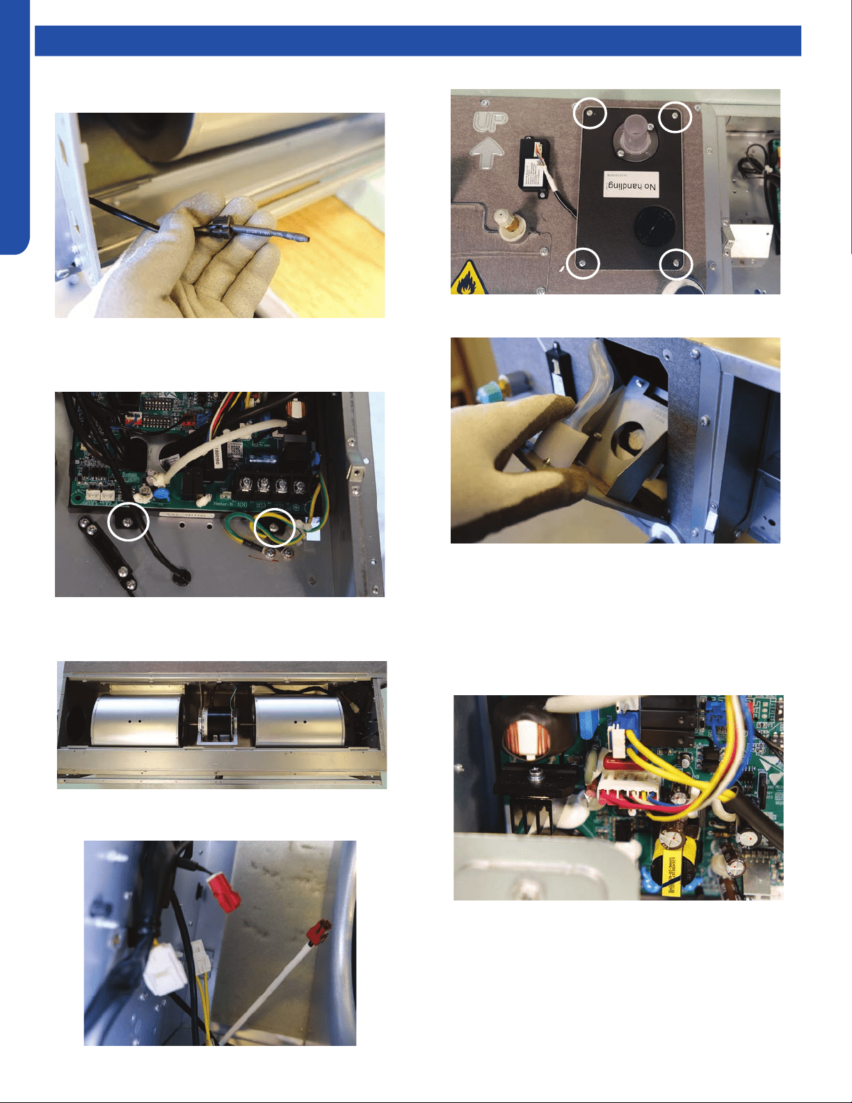
MID-STATIC DUCTED TECHNICAL OVERVIEW
G-10
ENGLISH
Topic TitleTesting
Board Replacement
1. Remove the ambient sensor.
Removing the Condensate Pump
1. Remove the air inlet cover.
2. Unplug all connectors from the board.
3. Remove the 2 board mounting screws and remove the
board.
2. Unplug the pump motor and oat switch wires from within
the air inlet
3. Remove the 4 screws holding the pump in place.
4. Tilt the pump out from the top and pull out
5. Pull wires through rubber grommets and remove pump
assembly
Removing Fan Motor
1. Remove control board cover.
2. Unplug motor wires.
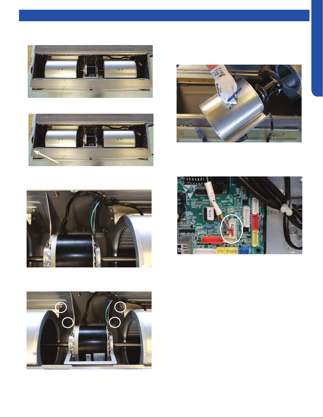
MID-STATIC DUCTED TECHNICAL OVERVIEW
G-11
ENGLISH
Topic TitleTesting
3. Feed motor wires into the air inlet box
4. Remove the air box cover.
5. Remove the corner bracket.
6. Remove the ground screw and free the motor wire
harness.
7. Remove the screws holding the blower housing to the unit,
4 on each housing.
8. Support the motor (2 people may be required at this time).
Loosen the 2 screws of the motor mount bracket and
remove full assembly
9. Using a long 4mm hex wrench, loosen the set screws from
the blower wheel and remove from motor shaft.
Replacing WiFi Module
1. Unplug existing WiFi module.
2. Insert new WiFi module.
3. Replace the wi passcode sticker.
4. Pair the unit to account.
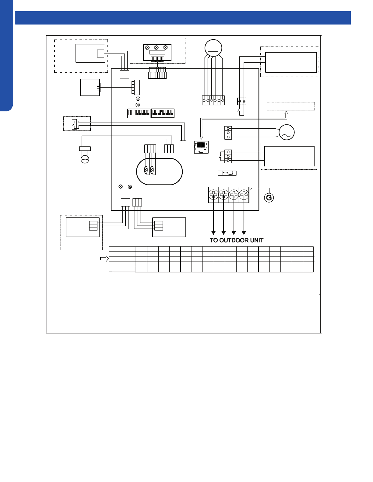
MID-STATIC DUCTED TECHNICAL OVERVIEW
G-12
ENGLISH
Topic TitleWiring Diagram
FRELAY FOR FRESH AIR
MOTOR(dry Contact
,rating-230VAC,3A) /E.A.0
FUSE
T250V 5A
CN1
1(L1)
G
AC PUMP
MOTOR
DC FAN
MOTOR
AB
C
AB
C
AB
C
A B
C
Tp
Tr
CN3
CN16
ROOM CARD
FLOAT SWITCH
ON ON
YCJ-A002
CN13
CN17
INFRARED SIGNAL RECEIVER
TO RJ 45 device
CN22-1
CN22
LED2
LED1
SW01
SW03
CN21
CN6
D
C
CN20
RJ45
LED3
LED4
Y/G
YL
YL
CN19
BLK
BLK
CN9
CN10
RD
BLK
WHT
YL
BLU
REMOTE
CENTRAL
CONTROL
ADAPTOR
2(L2) 3
In
≥ ≥
N
1
u
c
tim
c
2.
fai
un
NOTE:
1.Dashed
parts are optional.
2.Please refer to service manual to get details of the DIP switches definition .
3.Do not change the DIP switches setting without technical support.
4.Get details from trouble shooting list about LED indication.
5.Abbreviation
:
RD -red, W -withe, BLK -black,BLU-blue,GRN-green,YL-yellow,Y/G -yellow/green,E.A.O:
external alarm output,Tr
:
indoor unit ambient(room) temperature sensor,Tp
:
indoor unit pipe(coil)
temperature sensor.
6.The port CN4&CN10are dry contact output port for particular use,do not connect other device without
technical person support.
M
M
WIRED
CONTROLLER
WIRED
CONTROLLER
123
45
6
7
8
123
45
6
7
8
CN4
P1 P2
RELAY FOR AUXILIARY
(dry contact port,contact
rating 230VAC,3A
BLU
GRN
BLU
W
RD
BLU
BLK
W
W
Factory default setting
of the DIP switches
SW1-1 SW1-2 SW1-3 SW1-4 SW1-5 SW1-6 SW1-7 SW1-8 SW3-1 SW3-2 SW3-3 SW3-4 SW3-5 SW3-6 SW3-7 SW3-8
USYM
09UCDSA1
USYM
12UCDSA1
USYM
18UCDSA1
USYM
24UCDSA1
MODEL
OFF OFF OFF OFF OFF OFF OFF OFF OFF OFF OFF OFF OFF OFF OFF
ON
12V
COM
GND
GND
COM
12V
W
W
WiFi MODULE
W
PGND
15V
VSP
FG
ON OFF OFF OFF OFF OFF OFF OFF OFF OFF OFF OFF OFF OFF OFF
ON
OFF OFF OFF OFF OFF OFF OFF OFF OFF OFF OFF OFF OFF
OFF ON
ON ON
OFF OFF OFF OFF OFF OFF OFF OFF OFF OFF OFF OFF OFF
ON
ON
0151539442
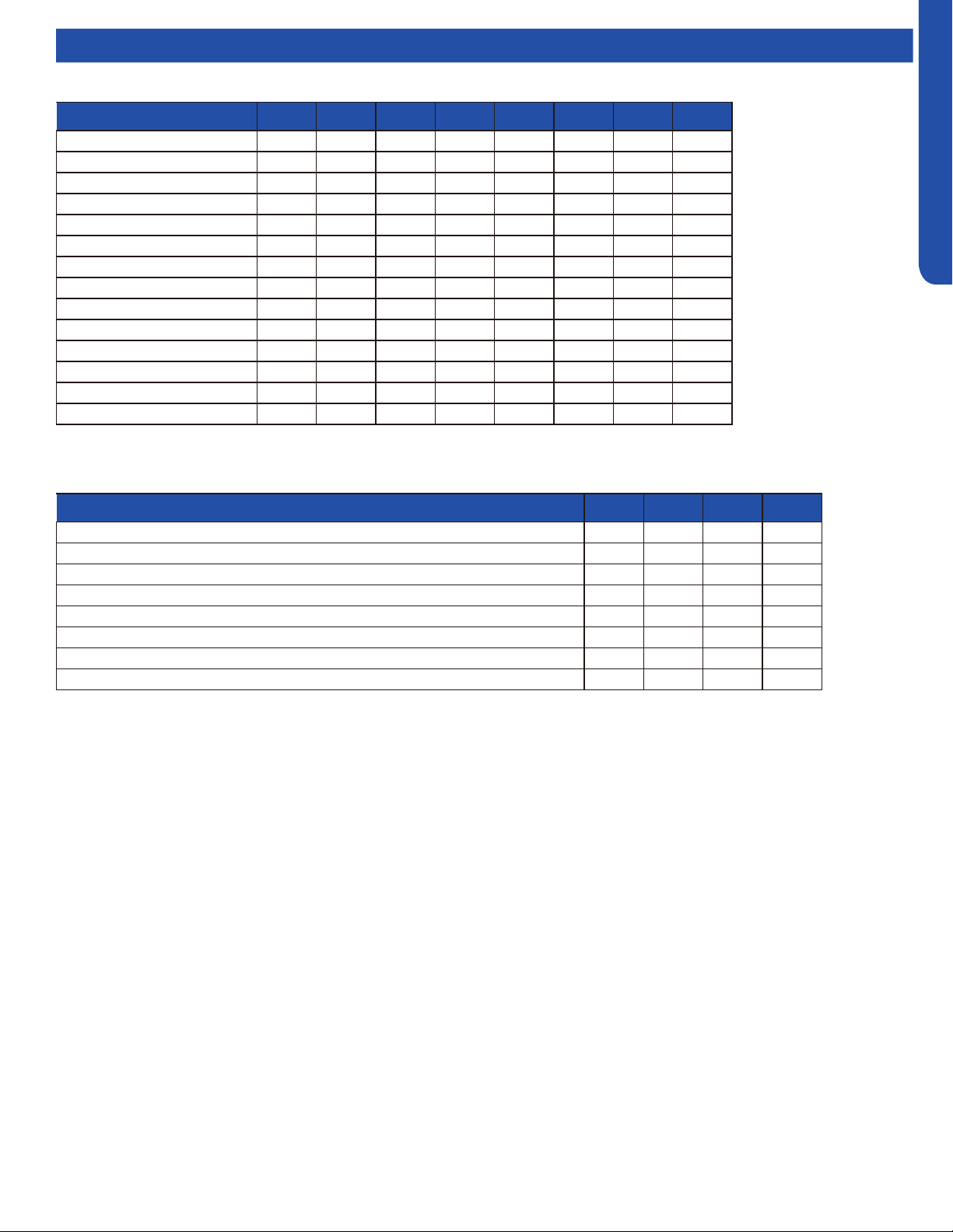
MID-STATIC DUCTED TECHNICAL OVERVIEW
G-13
ENGLISH
DIP Switch Settings
Description SW1-1 SW1-2 SW1-3 SW1-4 SW1-5 SW1-6 SW1-7 SW1-8
Capacity: 9000btu/h OFF OFF OFF --- --- --- --- ---
Capacity: 12000btu/h ON OFF OFF --- --- --- --- ---
Capacity: 18000btu/h OFF ON OFF --- --- --- --- ---
Capacity: 24000btu/h ON ON OFF --- --- --- --- ---
Room card invalid --- --- --- OFF* --- --- --- ---
Room card valid --- --- --- ON --- --- --- ---
Heat pump --- --- --- --- OFF* --- --- ---
Cooling only --- --- --- --- ON --- --- ---
Fresh air valid --- --- --- --- --- OFF* --- ---
External alarm output --- --- --- --- --- ON --- ---
Without filter clean warning --- --- --- --- --- --- OFF* ---
With filter clean warning --- --- --- --- --- --- ON ---
North America area --- --- --- --- --- --- --- OFF*
Non-North America area --- --- --- --- --- --- --- ON
Description SW3-1 SW3-2 SW3-3 SW3-4
Special fresh air (Canadian ventilation mode, Canada particular Area) invalid OFF* --- --- ---
Special fresh air (Canadian ventilation mode, Canada particular Area) valid ON --- --- ---
Console/MESP Duct --- OFF* --- ---
Cassette (Reserved) --- ON --- ---
Auxiliary heater invalid --- --- OFF* ---
Auxiliary heater valid --- --- ON ---
ESP grade 0-4 level --- --- --- OFF
ESP grade 0-10 level --- --- --- ON*
SW1 DIP Switch Settings
SW3 DIP Switch Settings
*Factory Default Setting
*Factory Default Setting
MID-STATIC DUCTED TECHNICAL OVERVIEW
G-14
ENGLISH
Error Codes
The error codes that are displayed on the indoor units may vary from the outdoor unit codes. The information communicated by
the error code will be the SAME for both indoor and outdoor units even though the numbers may dier.
Indoor
LED4
Indoor
LED3
Outdoor
LED
Diagnosis
2 1 1 Outdoor EEPROM failure
2 2 2 IPM overcurrent or short circuit
2 3 / Compressor over current during deceleration
2 4 4 Communication failure between the IPM and outdoor PCB
2 5 5 Module operated overload (compressor overload protection)
2 6 6 Module low or high voltage
2 7 / Compressor current sampling circuit fault
2 8 8 Overheat protection for discharge temperature
2 9 9 Malfunction of the DC fan motor
3 0 10 Malfunction of defrost temperature sensor
3 1 11 Suction temperature sensor failure
3 2 12 Ambient temperature sensor failure
3 3 13 Discharge temperature sensor failure
3 4 / PFC circuit loop voltage
3 5 15 Communication failure between the indoor & outdoor unit
3 6 16 Lack of refrigerant or discharging
3 7 17 4-way valve switching failure
3 8 18 Loss of synchronism detection
3 9 / Low DC or AC voltage
4 0 20 Indoor thermal overload
4 1 21 Indoor coil frosted
4 2 / PFC circuit loop overcurrent
4 3 23 Module thermal overload
4 4 24 Compressor start failure, over-current
4 5 25 Phase current protection (IPM)
4 6 26 MCU reset
4 7 27 Module current detect circuit malfunction
4 8 28 Liquid pipe sensor failure: Circuit A
4 9 29 Liquid pipe sensor failure: Circuit B
5 0 30 Liquid pipe sensor failure: Circuit C
5 1 31 Liquid pipe sensor failure: Circuit D
5 2 32 Gas pipe sensor failure: Circuit A
5 3 33 Gas pipe sensor failure: Circuit B
5 4 34 Gas pipe sensor failure: Circuit C
5 5 35 Gas pipe sensor failure: Circuit D
5 6 36 Gas pipe sensor failure: Circuit E
5 7 / Compressor overcurrent detected by IPM
5 8 38 Malfunction of module temperature sensor momentary power failure detection
5 9 39 Malfunction of condensing temperature sensor
6 0 40 Liquid pipe sensor failure: Circuit E
6 1 41 Toci temperature sensor failure
6 2 42 High Pressure switch open
6 3 43 Low Pressure switch open
6 4 44 System high pressure protection: Overcharged, high condensing temperature or malfunction of fan motor
6 5 45 System low pressure protection: Undercharged, low defrosting temperature, or malfunction of fan motor
0 1 / Indoor ambient temperature sensor failure
0 2 / Indoor coil temperature sensor failure
0 4 / Indoor PCB EEPROM failure
0 7 / Communication fault between the indoor and outdoor unit
0 8 / Communication fault between the controller and Indoor unit
0 12 / Drain system malfunction
0 13 / Zero cross signal detected wrong
0 14 / Indoor fan motor malfunction
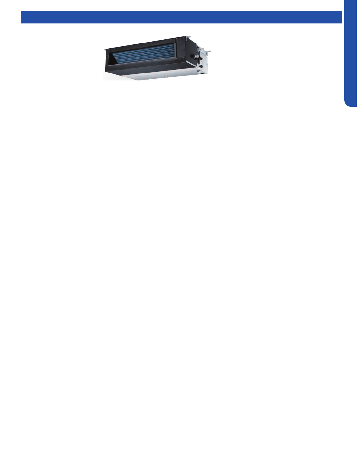
MEDIUM STATIC DUCTED (PRO SERIES) TECHNICAL OVERVIEW
H1
ENGLISH
MEDIUM STATIC DUCTED (PRO SERIES) TECHNICAL OVERVIEW
Table of Contents
Components ......................................................................................................................................................................... H-2
Component Overview ......................................................................................................................................................... H-2
Indoor Unit Circuit Board .....................................................................................................................................................H-3
Ductwork /Grilles .................................................................................................................................................................. H-5
Testing .................................................................................................................................................................................. H-6
Test Condensate Pump and Float Switch ...........................................................................................................................H-6
Testing Communication Circuit ..........................................................................................................................................H-6
Testing Temperature Sensors ............................................................................................................................................. H-7
Indoor Fan Motor Voltage Check ........................................................................................................................................ H-7
Wiring Diagram ..................................................................................................................................................................... H-8
DIP Switch Settings ..............................................................................................................................................................H-9
Error Codes .........................................................................................................................................................................H-10
AM24LP2VHA
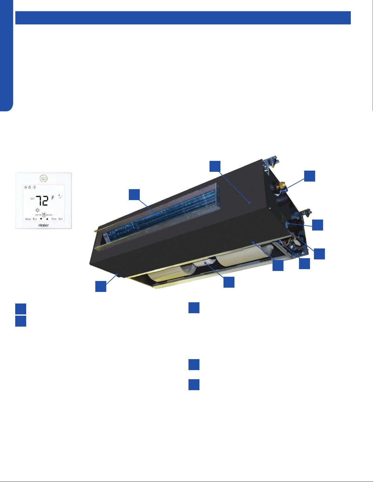
MEDIUM STATIC DUCTED (PRO SERIES) TECHNICAL OVERVIEW
H2
ENGLISH
Components
The Medium Static Ducted Indoor Unit will act as evaporator coils during cooling mode and condenser coils during heating mode.
This unit can operate with a motorized supply air louver or it can have a LIMITED amount of ducting added to the unit’s return
and supply air duct connection anges. The return air ducting can be connected to the end of the cabinet or the bottom blank o
plate can be removed for bottom return conguration.
DIP Switches on the unit’s circuit board congure the fan power to match the ducting conguration.
These units have a built in condensate pump with an associated condensate level switch. The condensate pump is capable of
lifting water out of the indoor unit. If high water lift is needed, the water from the cassette pump should be pumped into a eld
supplied condensate pump with high lift power.
The layout of the system is very straightforward and components are easily accessed should service be required. The blower
assembly and room air temperature sensor is accessed at the rear of the evaporator coil, and the piping temperature sensor
is located under the top cover. The condensate pump and oat switch are accessed under the removable panel next to the
electrical control box.
The wired controller can be congured to sense room air temperature. There is no option for use with remote control.
All operating status and information is displayed on the wired controller. The Medium Static Ducted unit does not have a display.
Medium Static Ducted
units are controlled by a
wired controller only.
8
8
6
4
4
2
2
7
5
5
3
3
1
1
Evaporator Coil
Blower Assembly
The indoor unit features a DC variable speed dual shaft
blower motor that will change speed to match the
capacity demand from the outdoor unit. The motor
is a dual shaft type that powers two individual blower
assemblies.
The blower assembly consists of 2 plastic blowers. A set
screw holds each blower wheel to the blower motor.
The indoor blower motor is connected to the indoor
unit control board. The wiring from the motor to indoor
board consists of 5 wires connected to pins that deliver
line voltage, speed, and feedback information.
During normal operation, the indoor control board will
energize the indoor blower motor and request proper
speed. Fan power should be set using the DIP Switches
SW1 settings.
Terminal Block
Power to operate the indoor unit comes from the
electrical line voltage terminal block at the outdoor unit.
The wiring includes 4 wires, 1, 2, 3 and ground. Wires 1
and 3 complete the data path. These wires should always
be 14 gauge AWG Stranded type wire. Splices in wires 1
or 3 may cause communication errors.
Control Board
Located under the electrical control box cover.
Ambient Temperature Sensor
The Ambient Temperature Sensor senses room
temperature. This sensor provides room temperature
information to the ECU for calculation of inverter
capacity and temperature control.
Component Overview
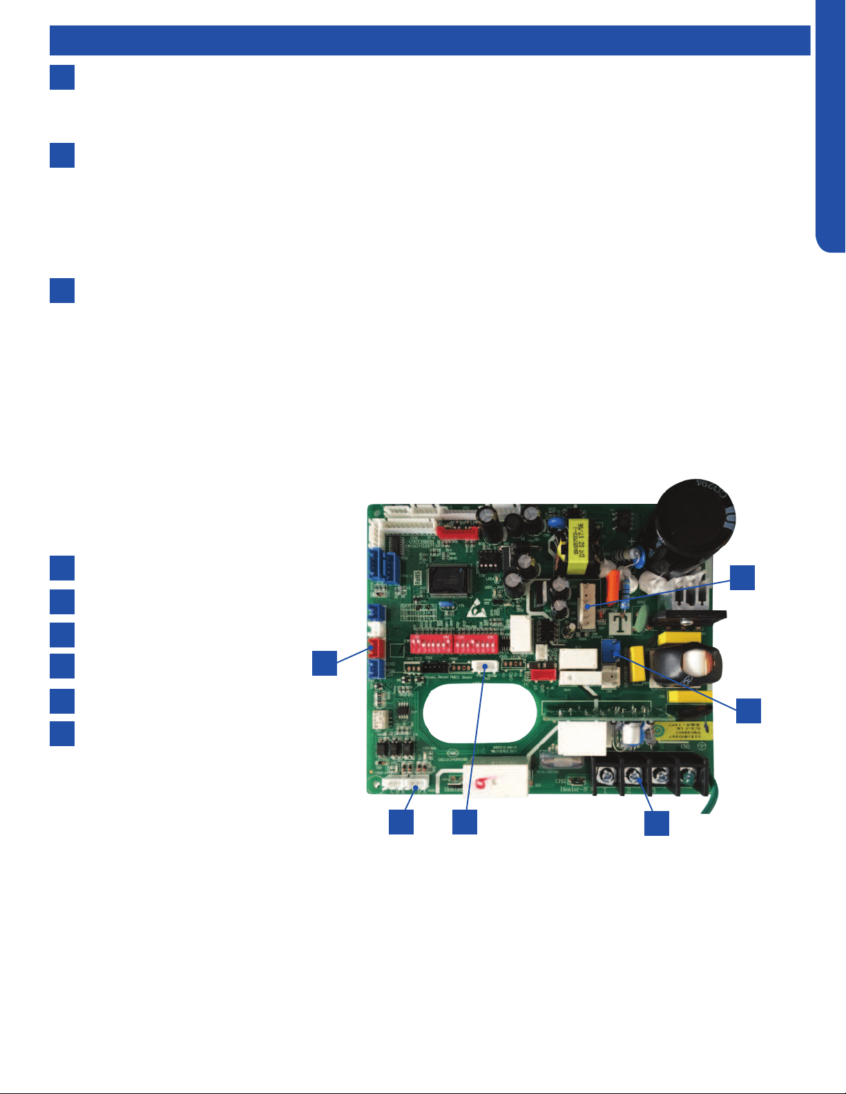
MEDIUM STATIC DUCTED (PRO SERIES) TECHNICAL OVERVIEW
H3
ENGLISH
Components
8
6
7
Piping Temperature Sensor
The Piping Temperature Sensor senses indoor coil temperature in the cooling mode and in the heating mode. This sensor is
used for Anti Freezing and Anti Cold Blow cycles. The sensor also provides critical temperature information to the ECU that
may be used in frequency adjustments.
Condensate Pump
The Medium Static Ducted unit has a built in condensate pump. The pump is connected to the circuit board. The pump
is energized whenever the Float Switch indicates that water needs to be pumped from the cassette. The oat switch
connects onto the circuit board.
The oat switch and pump are located behind the removable insulated cover next to the electrical control box. The pump
is hermetically sealed and requires no maintenance. The oat switch is a normally closed switch, that opens as water rises.
The oat switch requires no maintenance.
Gravity Drain Ports
The indoor unit has the option for either gravity drain systems or the use of an internal condensate pump with oat switch.
The pump is capable of minimal lift. If high lift is required, the water from the Medium Static Ducted unit should be pumped
to a eld supplied condensate pump that is capable of high lift.
Indoor Unit Circuit Board
The indoor unit circuit board controls the switching functions of the indoor unit. All control decisions are made by the outdoor
unit ECU. The indoor board has some limited diagnostic capability which will be covered in this manual.
1
4
2
5
6
3
CN13 Float switch
CN22 Wired controller
CN41 Ambient and Coil sensors
CN4 Condensate pump
CN6 Blower motor
Terminal Block
1
3
2
5
4
6
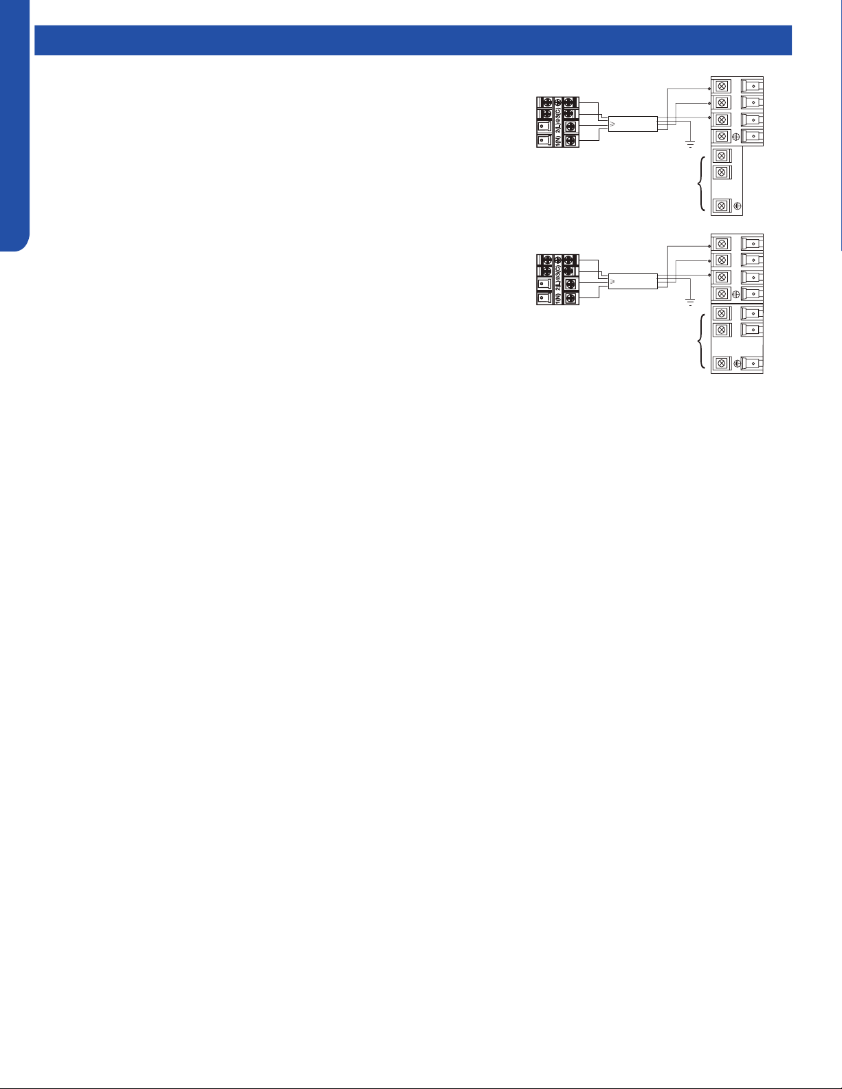
MEDIUM STATIC DUCTED (PRO SERIES) TECHNICAL OVERVIEW
H4
ENGLISH
This control board has control over the fan louver movement, manual fan blower control, indoor coil temperature and indoor air
temperature sensing functions. All operational decisions are controlled by the OUTDOOR UNIT ECU.
The control board has a replaceable 5A 250V fuse that protects against excessive current. If power is present at the board but the
board does not work, check for continuity through the fuse. Replace if the fuse is open.
The indoor unit temperature sensors are connected at Plug CN-13. When testing the calibration of these sensors, the wires can
be released from the plug by pressing on the tension tab on the side of the plug.
There 3 motors that control the directional movement of the accessory louver. The motor connects to the circuit board at Plug
CN-14, CN-15 and CN-16. The motors are located in the louver assembly.
The blower motor is connected to the circuit board at plug CN-6.
Components
The Indoor Unit Circuit Board communicates with the outdoor unit ECU
via a connection at Terminal Block screw 3. The data pulse that sends the
communication information can be measured with a voltmeter placed to DCV
range. From the ground connection at the Terminal Block to the Number 3
screw connection, the voltage should pulse up and down when data is being
transmitted.
Line voltage to power the indoor unit comes in on Terminal Block connections 1
and 2. Power connects from these terminal connections to CH- 1 and CH-2 on
the circuit board. If the board does not respond to commands and has no display,
check for line voltage at these connections. When power is present at the indoor
board, the wired controller will be energized.
The connections on the indoor board are shown here in the schematic drawing.
Outdoor unit
3
2
Power
Wiring
1
)
(
N
)
(L
)
(
C
3
2
1
)
(
N
)
(
L
)
(
C
Indoor uni
t
3wire 14AWG
Control Wiring
Outdoor unit
3
2
Power
Wiring
1
)
(
N
)
(L
)
(
C
2
1
)
(
N
)
(
L
Indoor uni
t
3wire 14AWG
Control Wiring

MEDIUM STATIC DUCTED (PRO SERIES) TECHNICAL OVERVIEW
H5
ENGLISH
Topic TitleDuctwork / Grilles
Ductwork Installation
Use rivet to connect the
air return duct on the air
return inlet of the indoor
unit, then connect the
other end with the air
return
Indoor unit
Soft
connection
or static
box
Transition
duct
Rounded
duct
Tie-in of air
distribution
Air distribution
Air return blind Air return duct
Indoor unit
Rivet
gluey nail
heat
preservation cotton
tinfoil
gluey nail cap
adhesive tape
Roof Installation
Ceiling
Air supply
Unit
Return air
Return air box
Roof
Air outlet grill
Air supply
Unit
Return air box
Return air
Long Duct
Suspending hook
Drain pipe
Air return duct
Air return blind
Air out duct
Transition duct
Tie-in of air
Distribution
Air distribution
Basic Duct Congurations
Here are the typical duct congurations that can be used with the unit.
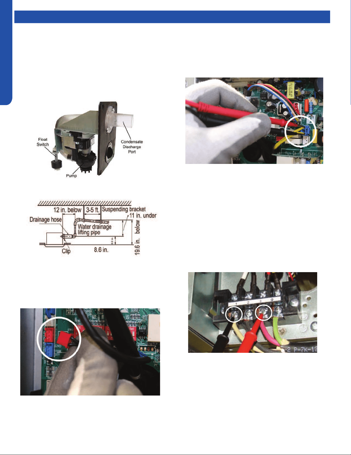
MEDIUM STATIC DUCTED (PRO SERIES) TECHNICAL OVERVIEW
H6
ENGLISH
Topic TitleTesting
If the internal condensate pump does not operate, the pump
may be bad or the oat switch may be defective. Perform the
following test:
1. Access the electrical control box.
2. Unplug the oat switch from the circuit board.
Test Condensate Pump and Float Switch
The unit has a built-in condensate pump and water level
safety switch. There are also two optional ports for gravity
drainage. The condensate pump is rated to lift water up to 27
9/16” from the point of discharge.
The unit comes with a grey connection hose with clamp. This
hose is connected to the High ESP Duct unit condensate
discharge hose port. The other end of the hose is sized to
accept 3/4 inch PVC piping.
Recommended condensate piping congurations are shown
here:
3. The pump should start.
4. IIf the pump does not start, check for voltage at the pump
control board connection. There should be 230 Volts AC
to the pump. If there is not, the circuit board is defective.
If there is proper voltage to the pump, either the pump or
associated pump wiring is defective.
Testing Communication Circuit
If an Error E7 occurs, perform the following test to determine
if the indoor control board is functioning properly to send data
to the outdoor unit.
Perform this test with the unit powered and all wiring
connected between indoor and outdoor unit.
Make sure all wiring between the indoor and outdoor unit
are correct. There should no splices between the indoor and
outdoor unit wiring connecting terminals 1 or 3. Make sure
wiring is correct, before performing this test.
1. Measure the DC voltage between terminals 1 and 3 on the
indoor terminal block.
2. The voltage should uctuate between 8VDC and 23VDC.
The uctuating signal indicates a good communication
path.
3. If the voltage does not uctuate, and the wiring is good,
the indoor board is defective.

MEDIUM STATIC DUCTED (PRO SERIES) TECHNICAL OVERVIEW
H7
ENGLISH
Topic TitleTesting
Testing Temperature Sensors
The easiest problems to solve will involve codes that are
related to potential failure of temperature sensors. Common
problems may include loose connections, open electrically,
and out of calibration. Checking the condition of the sensors
requires a temperature probe and an ohmmeter.
The Reference Section of this manual contains temperature
resistance tables that can be used to check the calibration
of the sensors. The measured resistance must be within the
tolerances printed on the top of the tables.
1. Conrm the sensor is rmly attached to the circuit board
connection plug.
2. Remove the sensor wires from the connection plug by
releasing holding tension on the plugs tension tab.
3. Use an ohmmeter to test the electrical resistance of the
sensor.
4. Measure the air temperature near the sensor and compare
the required resistance against measured resistance.
(refer to charts in reference section) If the sensor is
within calibration, the sensor is good. If the sensor is out
of calibration, replace the sensor. (Tube Sensors should
be removed from socket and exposed to air temperature
during test.)
If The Indoor Fan Motor Does Not Run:
1. Remove the front cover and access the fan motor circuit
board connection.
2. Reset power and turn the remote control fan command to
Fan On mode.
Motor Test:
1. If the motor doesn’t run, check for 310VDC between Pins 1
and 3. If it is not present, the indoor board is bad. If voltage
is present, continue on.
2. Check the voltage between Pins 3 and 4. The voltage
should be +15VDC. If it is not present, the board is bad. If
voltage is present, continue on.
3. Check for voltage between Pins 3 and 6. If no DC voltage is
present, the board is bad. If voltage is present, change the
motor.
Indoor Fan Motor Voltage Check
1
2
3
DC Motor
+310 VDC
DC Ground
+15 VDC
Signal
Feedback
Red
Black
White
Yellow
Blue
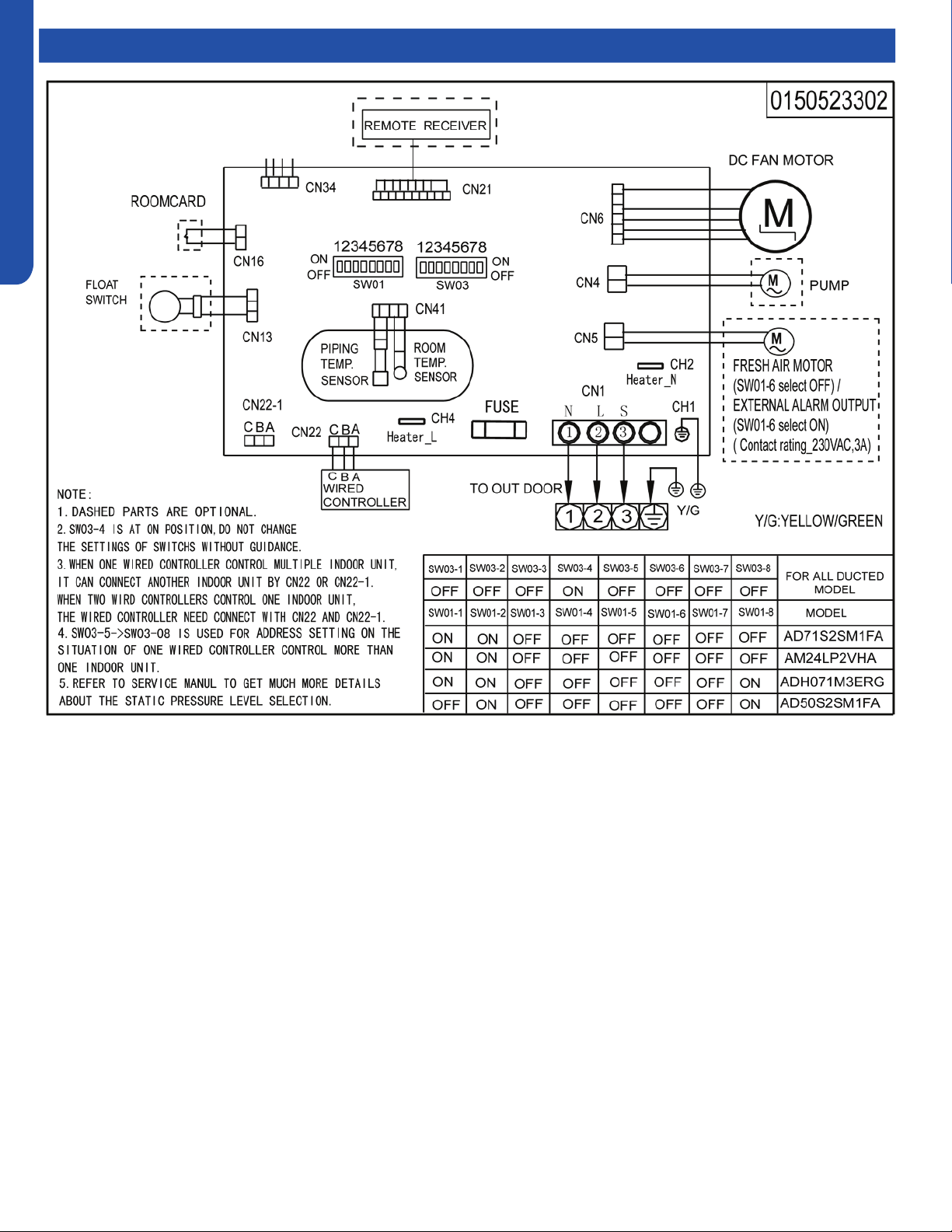
MEDIUM STATIC DUCTED (PRO SERIES) TECHNICAL OVERVIEW
H8
ENGLISH
Topic TitleWiring Diagram
MEDIUM STATIC DUCTED (PRO SERIES) TECHNICAL OVERVIEW
H9
ENGLISH
DIP Switch Settings
Description SW1-1 SW1-2 SW1-3 SW1-4 SW1-5 SW1-6 SW1-7 SW1-8
AM24LP2VHA ON ON OFF --- --- --- --- ---
Room card invalid(default) --- --- --- OFF --- --- --- ---
Room card valid --- --- --- ON --- --- --- ---
Cool and heat(default) --- --- --- --- OFF --- --- ---
Cool only --- --- --- --- ON --- --- ---
External alarm
output(default)
--- --- --- --- --- OFF --- ---
Fresh air --- --- --- --- --- ON --- ---
Without filter clean remind
(default)
--- --- --- --- --- --- OFF ---
With filter clean remind --- --- --- --- --- --- ON ---
ESP DUCT ( USA) --- --- --- --- --- --- OFF 0
EU. & Australia --- --- --- --- --- --- --- ON
Indoor unit Address
(Indoor unit address for one wired
controller control more than one unit)
SW3-5 SW3-6 SW3-7 SW3-8
0 (master) OFF OFF OFF OFF
1 (slave) OFF OFF OFF ON
2 (slave) OFF OFF ON OFF
3 (slave) OFF OFF ON ON
4 (slave) OFF ON OFF OFF
5 (slave) OFF ON OFF ON
6 (slave) OFF ON ON OFF
7 (slave) OFF ON ON ON
8 (slave) ON OFF OFF OFF
9 (slave) ON OFF OFF ON
10 (slave) ON OFF ON OFF
11 (slave) ON OFF ON ON
12 (slave) ON ON OFF OFF
13 (slave) ON ON OFF ON
14 (slave) ON ON ON OFF
15 (slave) ON ON ON ON
Wired Controller Communication Address
MEDIUM STATIC DUCTED (PRO SERIES) TECHNICAL OVERVIEW
H10
ENGLISH
Error Codes
The error codes that are displayed on the indoor units may vary from the outdoor unit codes. The information communicated by
the error code will be the SAME for both indoor and outdoor units even though the numbers may dier.
Indoor
LED4
Indoor
LED3
Outdoor
LED
Diagnosis
2 1 1 Outdoor EEPROM failure
2 2 2 IPM overcurrent or short circuit
2 3 / Compressor over current during deceleration
2 4 4 Communication failure between the IPM and outdoor PCB
2 5 5 Module operated overload (compressor overload protection)
2 6 6 Module low or high voltage
2 7 / Compressor current sampling circuit fault
2 8 8 Overheat protection for discharge temperature
2 9 9 Malfunction of the DC fan motor
3 0 10 Malfunction of defrost temperature sensor
3 1 11 Suction temperature sensor failure
3 2 12 Ambient temperature sensor failure
3 3 13 Discharge temperature sensor failure
3 4 / PFC circuit loop voltage
3 5 15 Communication failure between the indoor & outdoor unit
3 6 16 Lack of refrigerant or discharging
3 7 17 4-way valve switching failure
3 8 18 Loss of synchronism detection
3 9 / Low DC or AC voltage
4 0 20 Indoor thermal overload
4 1 21 Indoor coil frosted
4 2 / PFC circuit loop overcurrent
4 3 23 Module thermal overload
4 4 24 Compressor start failure, over-current
4 5 25 Phase current protection (IPM)
4 6 26 MCU reset
4 7 27 Module current detect circuit malfunction
4 8 28 Liquid pipe sensor failure: Circuit A
4 9 29 Liquid pipe sensor failure: Circuit B
5 0 30 Liquid pipe sensor failure: Circuit C
5 1 31 Liquid pipe sensor failure: Circuit D
5 2 32 Gas pipe sensor failure: Circuit A
5 3 33 Gas pipe sensor failure: Circuit B
5 4 34 Gas pipe sensor failure: Circuit C
5 5 35 Gas pipe sensor failure: Circuit D
5 6 36 Gas pipe sensor failure: Circuit E
5 7 / Compressor overcurrent detected by IPM
5 8 38 Malfunction of module temperature sensor momentary power failure detection
5 9 39 Malfunction of condensing temperature sensor
6 0 40 Liquid pipe sensor failure: Circuit E
6 1 41 Toci temperature sensor failure
6 2 42 High Pressure switch open
6 3 43 Low Pressure switch open
6 4 44 System high pressure protection: Overcharged, high condensing temperature or malfunction of fan motor
6 5 45 System low pressure protection: Undercharged, low defrosting temperature, or malfunction of fan motor
0 1 / Indoor ambient temperature sensor failure
0 2 / Indoor coil temperature sensor failure
0 4 / Indoor PCB EEPROM failure
0 7 / Communication fault between the indoor and outdoor unit
0 8 / Communication fault between the controller and Indoor unit
0 17 / DC voltage of the fan motor driver too high or too low
0 18 / Fan motor driver over 95°F (35°C)
0 19 / Indoor fan motor out of step
0 12 / Drain system malfunction
0 13 / Zero cross signal detected wrong
0 14 / Indoor fan motor malfunction
0 15 / Indoor fan motor overcurrent

CONSOLE TECHNICAL OVERVIEW
I-1
ENGLISH
CONSOLE TECHNICAL OVERVIEW
Table of Contents
Components ...........................................................................................................................................................................I-2
Component Overview ...........................................................................................................................................................I-2
Indoor Circuit Board...............................................................................................................................................................I-3
Testing ....................................................................................................................................................................................I-4
Removing the Filter Cover & Filter ........................................................................................................................................ I-4
Front Cover Removal .............................................................................................................................................................I-4
Control Box Removal .............................................................................................................................................................I-4
Board Replacement ...............................................................................................................................................................I-4
Upper Louver Removal ..........................................................................................................................................................I-5
Lower Damper Assembly Removal ....................................................................................................................................... I-5
Replace Fan Motor .................................................................................................................................................................I-5
Indoor Fan Motor Test Procedure .........................................................................................................................................I-6
Testing Temperature Sensors ...............................................................................................................................................I-7
Testing Louver Motors ..........................................................................................................................................................I-7
Testing Communication Circuit ............................................................................................................................................I-8
Replacing WiFi Module ...........................................................................................................................................................I-8
Wiring Diagram/DIP Switch Settings ......................................................................................................................................I-9
Error Codes ...........................................................................................................................................................................I-10
USYF09UCDWA
USYF12UCDWA
USYF18UCDWA
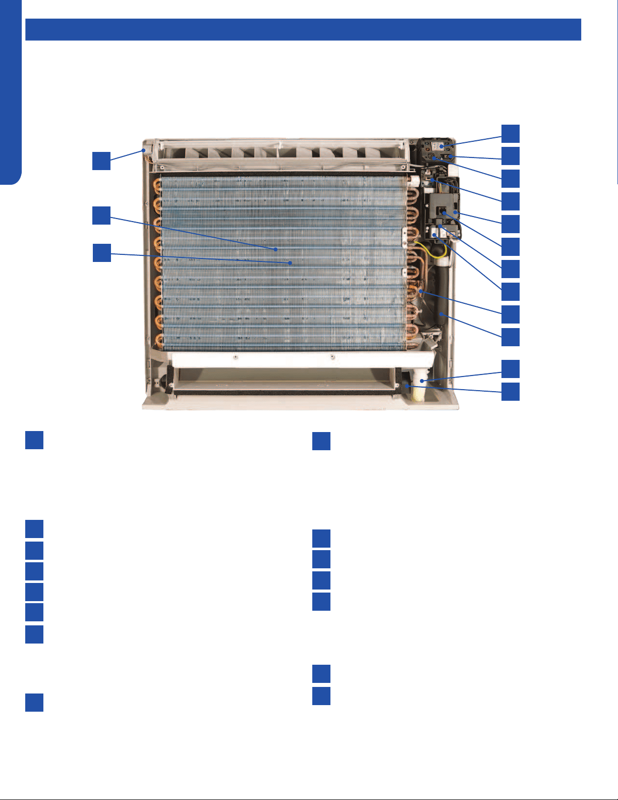
CONSOLE TECHNICAL OVERVIEW
I-2
ENGLISH
Components
The indoor console unit functions as an evaporator coil during cooling mode, and as a condensing coil during heat mode.
Condensate is collected by a drain pan below the coil and condensate is drained directly to the outdoor or to a secondary
condensate pump via the provided condensate drain line
Console units may be operated with either a wired remote control or the wireless remote control provided with the unit.
Component Overview
1
4
5
6
7
8
13
14
15
9
10
11
12
2
3
Display
The indoor unit display communicates system mode, but
does not display temperatures or diagnostic codes. This
information is indicated on the wired or wireless control.
When servicing a diagnostic error always refer to the
outdoor unit code.
IR Receiver
Power Switch
Lower Damper Control
Control Board Box
Diagnostic Port
Ambient Sensor
The Ambient Temperature Sensor senses room
temperature. This sensor provides room temperature
information to the ECU for calculation of inverter capacity
and temperature control.
WiFi Module
Coil Sensor
The Coil Temperature Sensor senses indoor coil
temperature in the cooling mode and in the heating
mode. This sensor is used for Anti Freezing and Anti
Cold Blow cycles. The sensor also provides critical
temperature information to the ECU that may be used in
frequency adjustments.
Flare Connections
Condensate Drain
Lower Damper Motor
Upper Louver Motor
The louver motor is a stepper type motor that moves
the louver left/right. The motor is controlled by a pulsed
voltage that cannot be measured. If the louver does not
move when it should, check for a bind in the louvers.
Blower Fan (behind coil)
Blower Motor (behind coil)
The indoor unit features a multi-speed blower motor
that will change speed to match the capacity demand
from the outdoor unit. The blower motor is controlled
by both the remote control and by commands from the
outdoor unit ECU
1
13
7
2
14
8
3
15
9
4
10
5
11
6
12
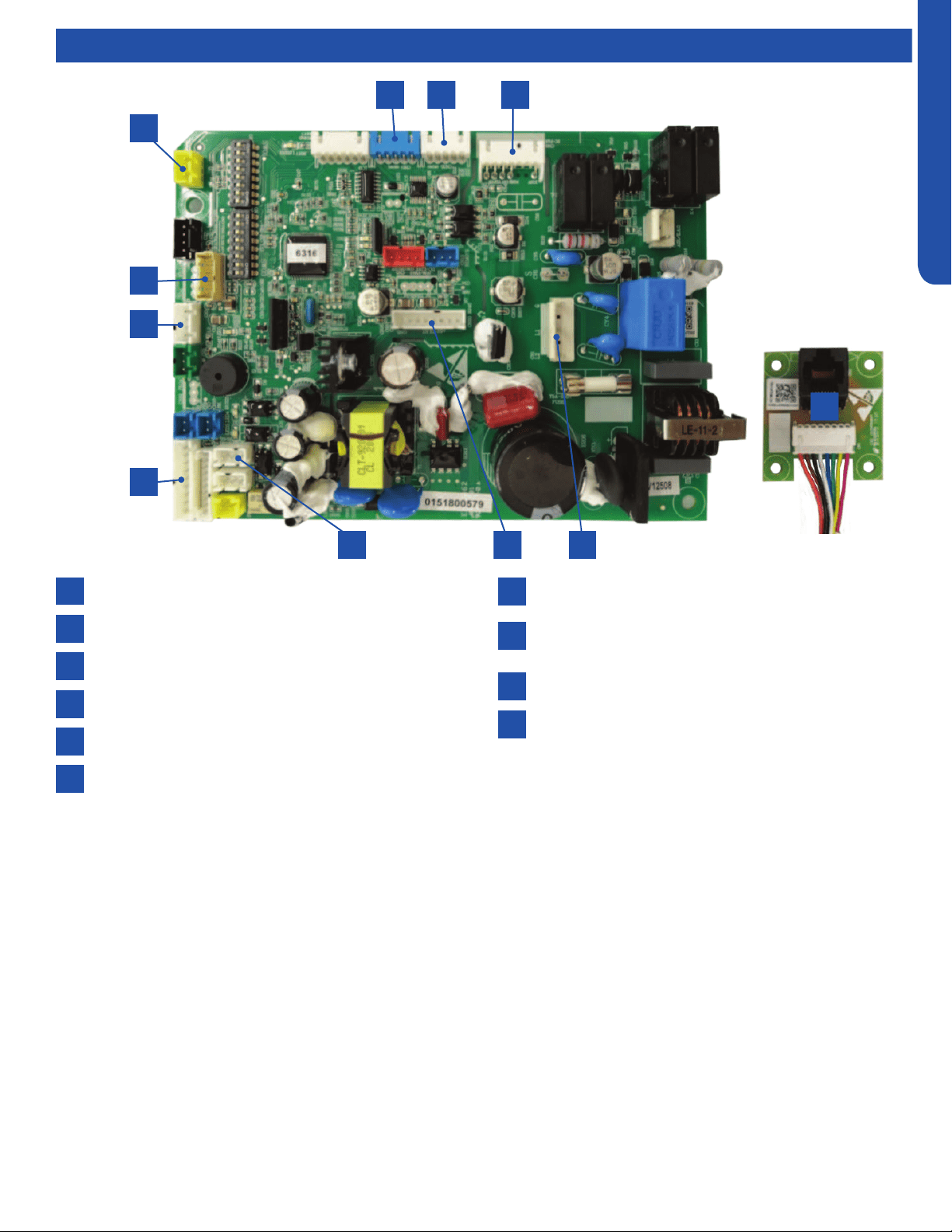
CONSOLE TECHNICAL OVERVIEW
I-3
ENGLISH
Indoor Circuit Board
Components
1
4
2
5
3
7
10
10
8
6
9
SW2-Damper switch
CN35- Lower damper motor
CN6-DC fan motor
Power supply
CN20-Diagnostic port
CN22- Optional wired controller
6 45
1
7
8
9
5 32
The indoor unit circuit board controls the switching functions of the indoor unit. All control decisions are made by the outdoor
unit ECU. The indoor board has some limited diagnostic capability which will be covered in this manual.
The indoor unit Circuit Board communicates with the outdoor unit ECU via a connection at terminal block screw 3. The data
pulse that sends the communication information can be measured with a voltmeter set to DC voltage range. From the ground
connection at the terminal block to the number 3 screw, voltage should pulse up and down when data is transmitted.
Line voltage to power the indoor unit is made on terminal block connections 1 and 2. Power connects from these terminal
connections to CH-3 and CH-4 on the circuit board. If the board does not respond to command and has no display, check for
line voltage at these connections. When power is present at the indoor board, the Display Power Indicator will be lit. The control
board has a replaceable 3.15A 250V fuse that protects against excessive current. If power is present at the board but the board
does not work, check for continuity through the fuse. Replace if the fuse is open.
The indoor unit sensors are connected at plug CN-13. When testing the calibration of these sensors the wires can be released
from the plug by pressing the tension tab on the side of the plug.
The receiver/display unit, mounted on the front cover of the indoor unit plugs connects to the circuit board at location CN-29.
The blower/fan motor connection is located at plug CN-11.
CN31- Display
CN3-Temperature sensor socket (Tr: ROOM SENSOR,
Tp:PIPE SENSOR)
CN17-WiFi module
RJ45 adapter board
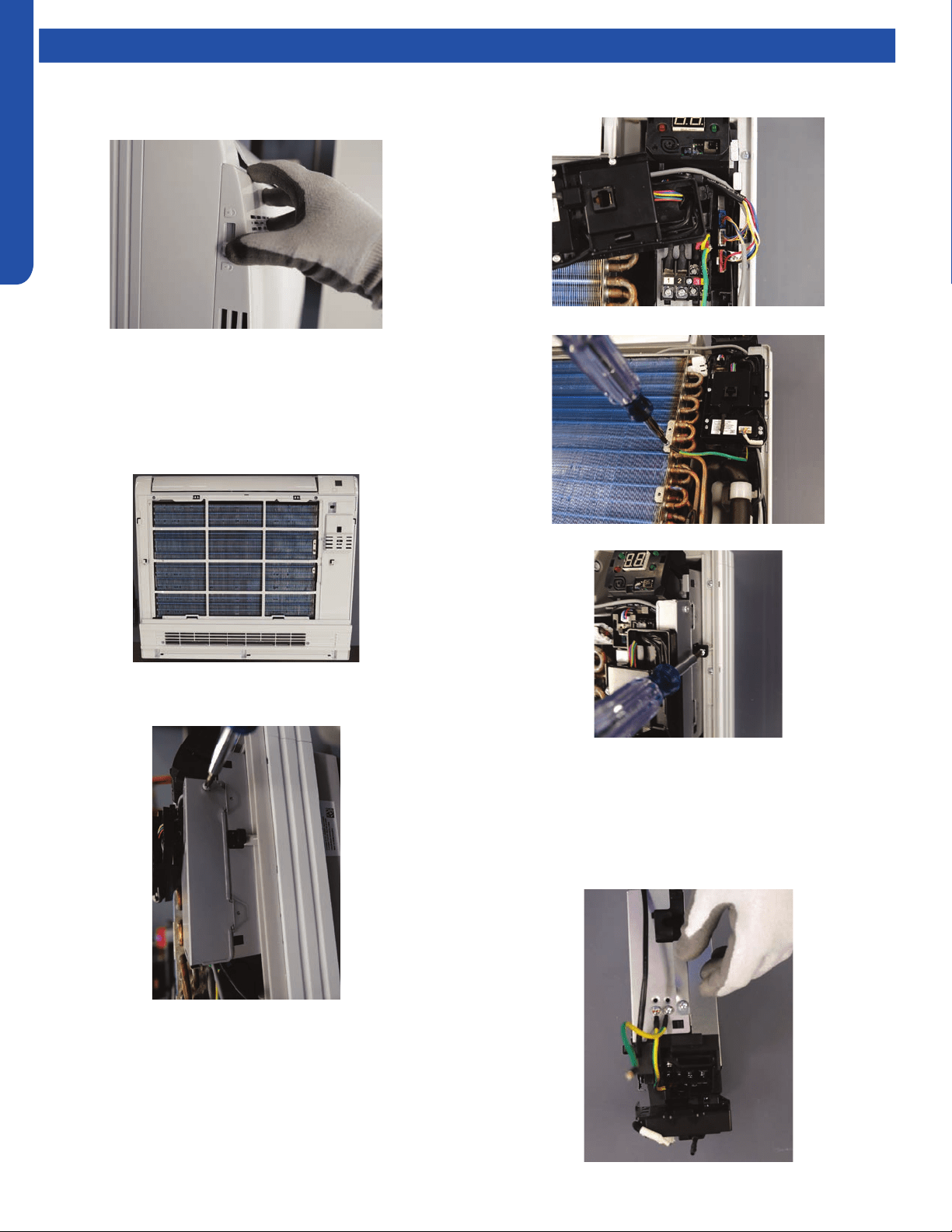
CONSOLE TECHNICAL OVERVIEW
I-4
ENGLISH
Topic TitleTesting
Removing the Filter Cover & Filter
1. Slide the side latches up to unlock the cover and pull
forward about an inch then lift up.
2. The lter is very exible and can be grabbed at any location
and removed.
Front Cover Removal
1. Remove the 4 screws that are at the corners of the air
intake opening. Gently open the horizontal louver. Lift up
the top edge of the front cover and then pull forward.
Control Box Removal
1. Remove the screw from the right side of the box cover.
2. Lift up the panel that contains the diagnostic port, wi
module and ambient sensor. And remove the box cover.
3. Unplug the three connectors for the fan motor, upper
louver and bottom damper.
4. Remove the ground screw.
5. Remove the mounting screw for the box.
6. The box can now be removed.
Board Replacement
1. Follow the instructions for removing the control box.
2. Remove the cover screw from the bottom of the box, then
remove cover.
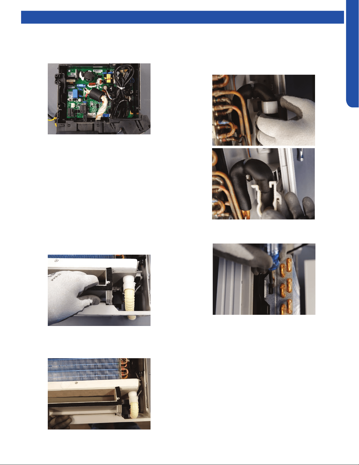
CONSOLE TECHNICAL OVERVIEW
I-5
ENGLISH
Topic TitleTesting
3. Take note of connection location and carefully remove
each connector.
4. Remove the 2 screws mounting the board in the box. They
in diagonal corners from each other.
Upper Louver Removal
1. Remove the lter cover and front cover.
2. Locate and remove the two screws mounting the upper
louver assembly to the case. They are on either end of the
assembly.
Lower Damper Assembly Removal
1. Remove the lter cover and front cover.
2. Disconnect the condensate drain.
3. Locate and remove the two screws mounting the damper
assembly to the case.
4. Pull on the right end of the assembly and rotate the
bottom of the assembly outward.
Note: When re-installing the damper assembly, rst place the
front edge of the condensate drain pan into place then rotate
the bottom of the assembly into position.
Replace Fan Motor
1. Remove lter cover, front panel, control box, upper louver
and bottom damper.
2. Remove the white plastic strap that hold the line set in
place on the right side of the unit.
3. Locate the locking tabs on the left side of the evaporator
and press them inward and pull the coil forward to remove.
IMPORTANT: Great care should be taken to when performing
this step. Excessively moving the lineset that connects to the
are can cause a refrigerant leak.
4. Slide the coil to the right to. The coil can now be gently
pulled away from the case. Only move the coil far enough
to access the four screws holding on the fan inlet faring.
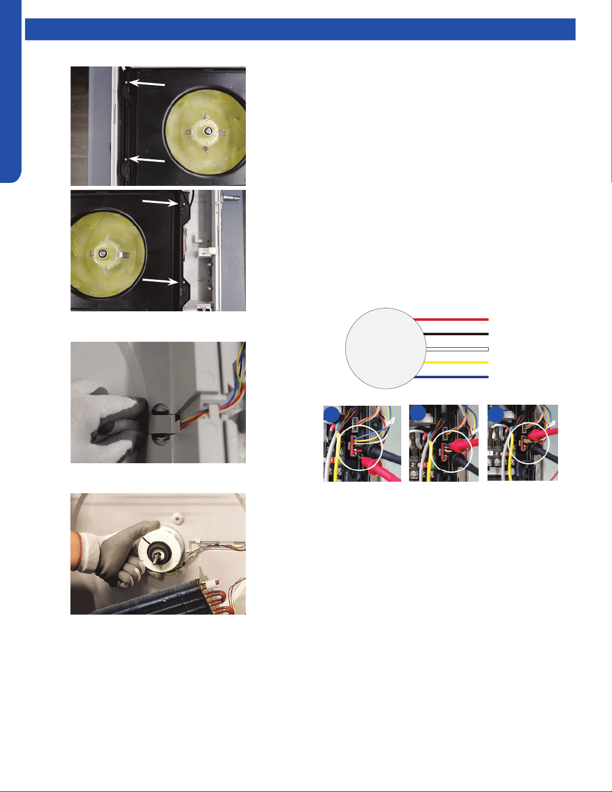
CONSOLE TECHNICAL OVERVIEW
I-6
ENGLISH
Topic TitleTesting
5. Remove the four screws holding on the fan inlet faring.
6. Remove the wire cover from the back of the case.
7. Remove the motor bracket.
NOTE: when replacing the motor, the wires must exit from
the bottom of the motor to prevent water from entering the
motor.
Indoor Fan Motor Test Procedure
If the indoor fan motor does not run:
1. Disconnect power to the system.
2. Remove the return air cover and access the fan motor
circuit board connection.
3. Reset power and turn the remote control fan command to
Fan On mode.
Motor Test:
1. If the motor doesn’t run, check for 310VDC between Pins 1
and 3. If it is not present, the indoor board is bad. If voltage
is present, continue on.
2. Check the voltage between Pins 3 and 4. The voltage
should be +15VDC. If it is not present, the board is bad. If
voltage is present, continue on.
3. Check for voltage between Pins 3 and 6. If no DC voltage
is present, the board is bad. If voltage is present, change
the motor.
DC Motor
+310 VDC
DC Ground
+15 VDC
Signal
Feedback
Red
Black
White
Yellow
Blue
1
2
3
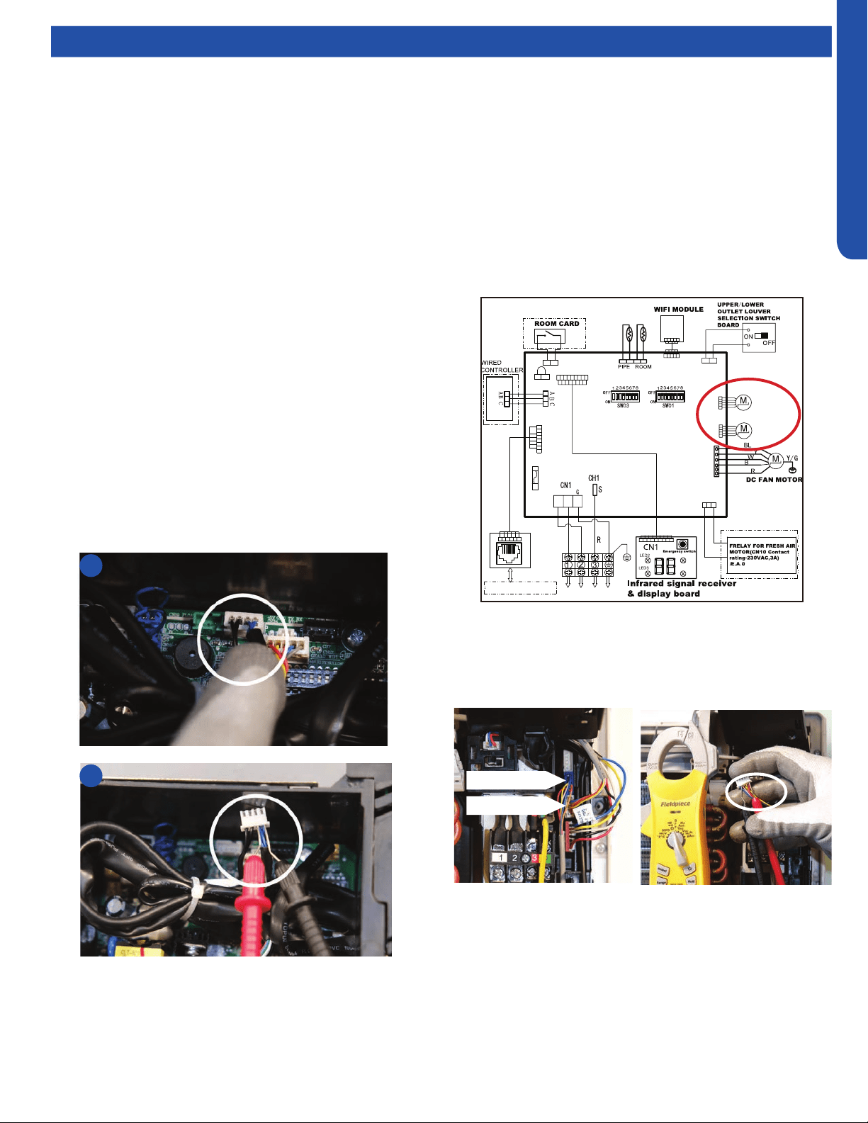
CONSOLE TECHNICAL OVERVIEW
I-7
ENGLISH
Topic TitleTesting
Testing Temperature Sensors
The easiest problems to solve will involve codes that are
related to potential failure of temperature sensors. Common
problems may include loose connections, open electrically,
and out of calibration. Checking the condition of the sensors
requires a temperature probe and an ohmmeter.
The Reference Section of this manual contains temperature
resistance tables that can be used to check the calibration
of the sensors. The measured resistance must be within the
tolerances printed on the top of the tables.
To test the electrical condition of a temperature sensor
perform the following:
1. Conrm the sensor is rmly attached to the circuit board
connection plug.
2. Remove the sensor wires form the connection plug by
releasing holding tension on the plugs tension tab.
3. Use an ohmmeter to test the electrical resistance of the
sensor.
4. Measure the air temperature near the sensor and compare
the required resistance against measured resistance.
(See chart in reference section) If the sensor is within
calibration, the sensor is good. If the sensor is out of
calibration, replace the sensor. (Tube Sensors should be
removed from socket and exposed to air temperature
during test.)
2
4
:
:
Tp
Tr
To Outdoor Unit
L2
L1
SW1
LED5
LED4
250VAC T5A
FUSE
CN20
CN22(22-1)
CN31
CN11
CN35
Main control board
Swing motor
for lower
louver
Swing motor
for upper
louver
CN10
CN6
CN3
CN17
SW2
CN16
CN16-1
W
B
W
BL
BL
W
W
W
YL
BL
W
W
RJ45 BOARD
To RJ45 DEVICE
Testing Louver Motors
If the louver does not operate with command from the remote
control, either the indoor board is bad, or the louver motor
is defective. It is more likely the motor is defective than the
board. (Make sure the louver assembly is not binding and
keeping the vanes from moving.)
1. Remove power from the unit and remove the indoor unit
cover.
2. Access the circuit board.
3. Identify the inoperable louver motor on the schematic
drawing below and disconnect the plug from the circuit
board.
4. Use an Ohmmeter to test the electrical continuity of the
louver motor windings. The proper resistance for each
winding should be 292Ω from red wire (common) to any
other wire.. If the motor winding resistance is erratic or
shows open, the motor is defective. Replace the motor.
5. If the motor checks out good, replace the indoor control
board.
Upper Louver
Lower Louver
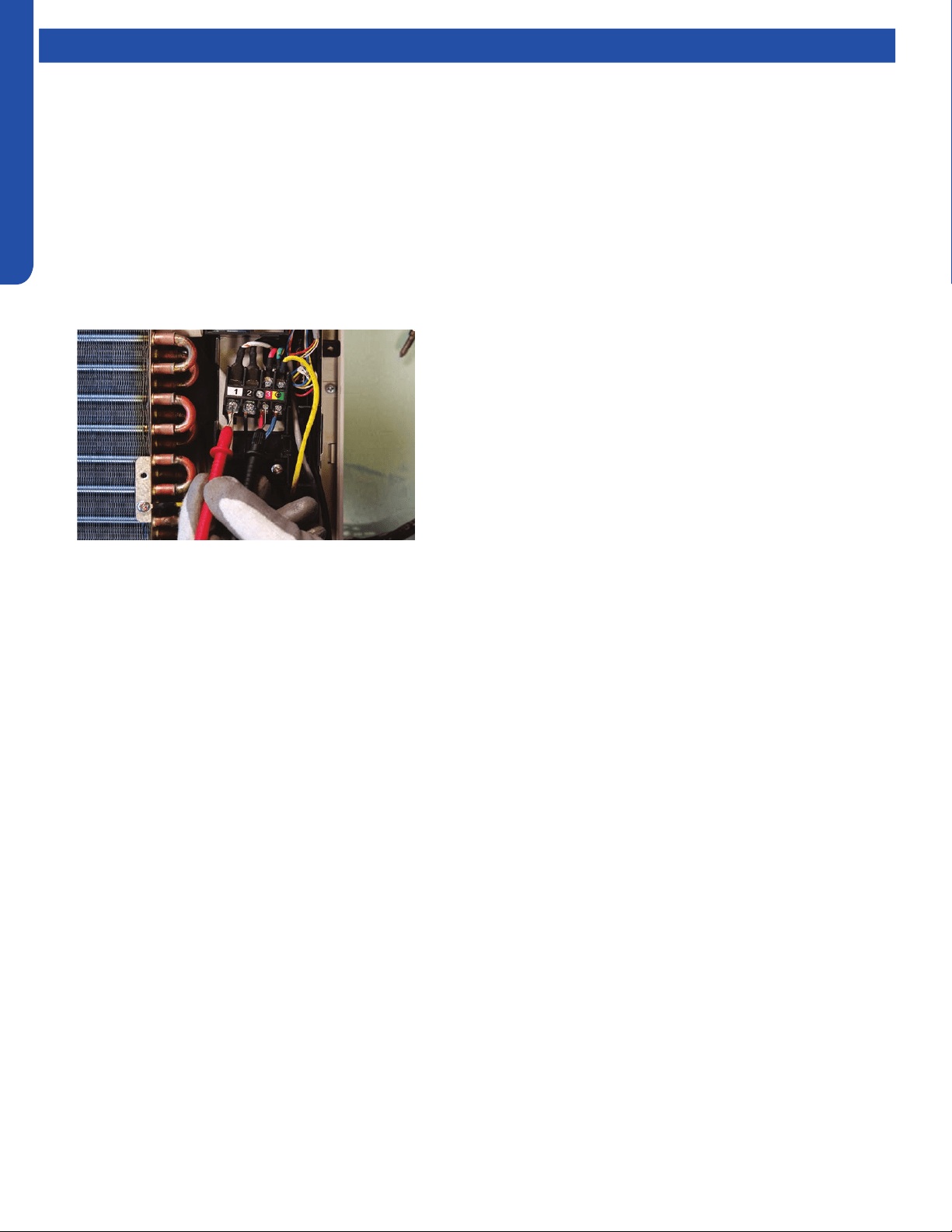
CONSOLE TECHNICAL OVERVIEW
I-8
ENGLISH
Topic TitleTesting
Testing Communication Circuit
If an Error E7 occurs, perform the following test to determine
if the indoor control board is functioning properly to send data
to the outdoor unit.
Perform this test with the unit powered and all wiring
connected between indoor and outdoor unit.
Make sure all wiring between the indoor and outdoor unit
are correct. There should no splices between the indoor and
outdoor unit wiring connecting terminals 1 or 3. Make sure
wiring is correct, before performing this test.
1. Measure the DC voltage between terminals 1 and 3 on the
indoor terminal block.
2. The voltage should uctuate between 8VDC and 23VDC.
The uctuating signal indicates a good communication
path.
3. If the voltage does not uctuate, and the wiring is good,
the indoor board is defective.
Replacing WiFi Module
1. Unplug existing WiFi module.
2. Insert new WiFi module.
3. Replace the wi passcode sticker.
4. Pair the unit to account.
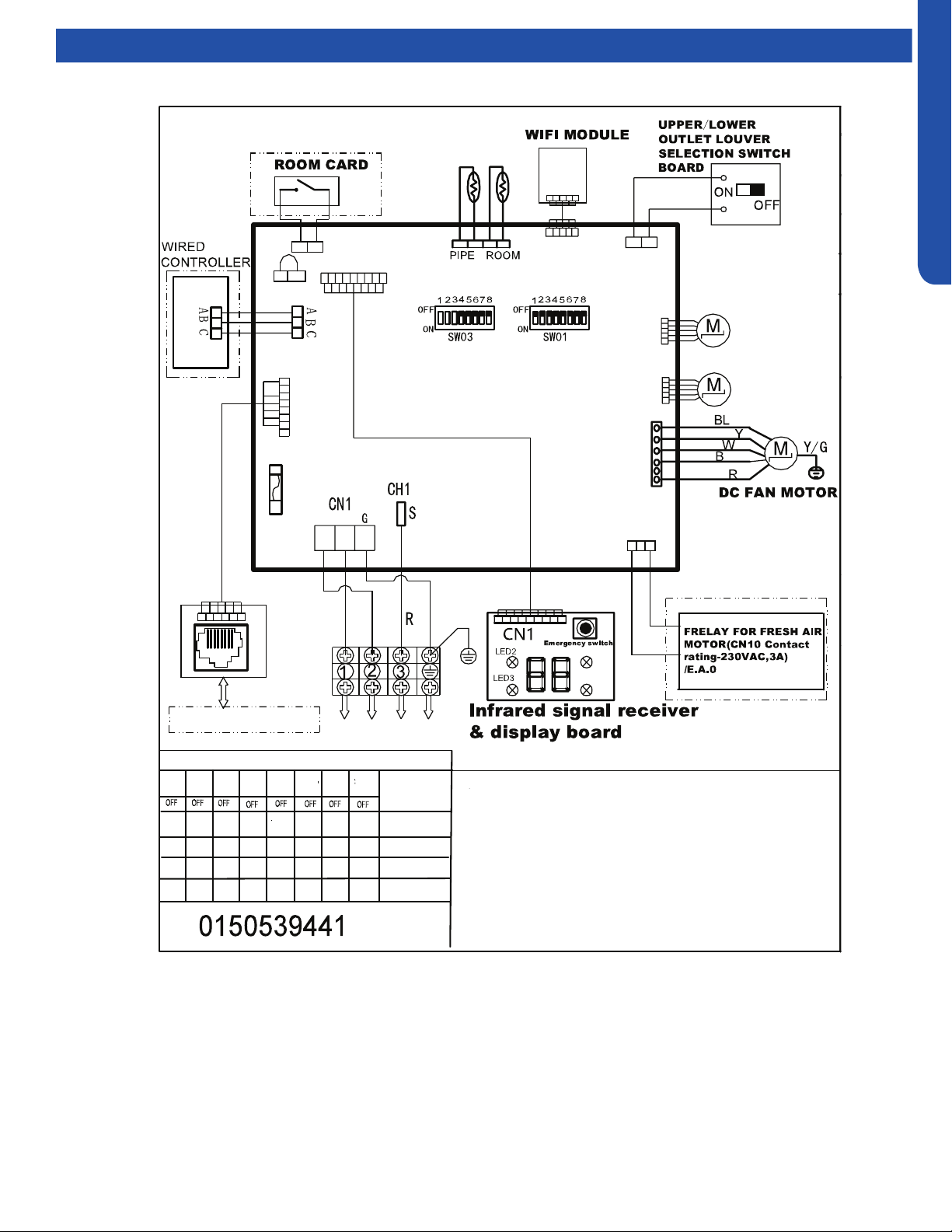
CONSOLE TECHNICAL OVERVIEW
I-9
ENGLISH
Wiring Diagram/DIP Switch Settings
USYF09UCDWA1
Note:
1.Dashed parts are optional.
2.Please refer to the technical service manual for detailed explanations
of DIP switches.
3.Do not change the DIP switches setting without technical support
4.Abbreviation:R-red ,B-black,BL-blue,W-white,Y/G-yellow/green,
TEMP.-temperature, E.A.O-exrernal alarm output,Tr-indoor unit
room temperature sensor ,Tp-indoor unit pipe temperature sensor (coil
temperature sensor)
Tp
Tr
SW1-1
OFF
OFF
SW1-2
OFF
OFF OFF
OFF
OFF
OFF
OFF
OFF
OFF OFF
OFF
OFF
OFF
ON
OFF
OFF OFF
OFF
OFF
OFFOFF
ON
SW1-3
SW1-4
SW1-5 SW1-6
SW1-7 SW1-8
To Outdoor Unit
All Console
default
MODEL
DIP switches factory default setting
L2
L1
SW1
LED5
LED4
250VAC T5A
FUSE
CN20
CN22(22-1)
CN31
CN11
CN35
Main control board
Swing motor
for lower
louver
Swing motor
for upper
louver
CN10
CN6
CN3
CN17
SW2
CN16
CN16-1
W
B
W
BL
BL
W
W
W
YL
BL
W
W
RJ45 BOARD
To RJ45 DEVICE
SW3-1
SW3-2 SW3-3
SW3-4
SW3-5 SW3-6
SW3-7 SW3-8
USYF12UCDWA1
USYF18UCDWA1
CONSOLE TECHNICAL OVERVIEW
I-10
ENGLISH
Error Codes
The error codes that are displayed on the indoor units may vary from the outdoor unit codes. The information communicated by
the error code will be the SAME for both indoor and outdoor units even though the numbers may dier.
Indoor
Display
Outdoor
LED
Diagnosis
F12 1 Outdoor EEPROM failure
F1 2 IPM overcurrent or short circuit
F22 / Outdoor alternating current, over current protection
F3 4 Communication failure between the IPM and outdoor PCB
F20* 5 Module operated overload (compressor overload protection)
F19* 6 Module low or high voltage
F27 / Compressor current sampling circuit fault
F4 8 Overheat protection for discharge temperature
F8* 9 Malfunction of the DC fan motor
F21 10 Malfunction of defrost temperature sensor
F7 11 Suction temperature sensor failure
F6 12 Ambient temperature sensor failure
F25 13 Discharge temperature sensor failure
F30* / High outdoor suction temperature
E7 15 Communication failure between the indoor & outdoor unit
F13* 16 Lack of refrigerant or discharging
F14* 17 4-way valve switching failure
F11 18 Loss of synchronism detection
F28 / Position detection circuit fault of compressor
F15* / Terminal block temp too high
F5* 23 Module thermal overload
F2* 24 Compressor start failure, over-current
F23 25 Phase current protection (IPM)
F9 26 MCU reset
F24 27 Module current detect circuit malfunction
F10 28 Liquid pipe sensor failure: Circuit A
F16 29 Liquid pipe sensor failure: Circuit B
F17 30 Liquid pipe sensor failure: Circuit C
F18 31 Liquid pipe sensor failure: Circuit D
F29 32 Gas pipe sensor failure: Circuit A
F30 33 Gas pipe sensor failure: Circuit B
F31 34 Gas pipe sensor failure: Circuit C
F32 35 Gas pipe sensor failure: Circuit D
F26 36 Gas pipe sensor failure: Circuit E
F34 / Outdoor pipe temperature protection in cooling mode
F35 38 Malfunction of module temperature sensor momentary power failure detection
F36 39 Malfunction of condensing temperature sensor
F33 40 Liquid pipe sensor failure: Circuit E
F38 41 Toci temperature sensor failure
F39 42 High Pressure switch open
F40 43 Low Pressure switch open
F41 44 System high pressure protection: Overcharged, high condensing temperature or malfunction of fan motor
F42 45 System low pressure protection: Undercharged, low defrosting temperature, or malfunction of fan motor
F43 / Incorrect match between indoor & outdoor
E1 / Indoor ambient temperature sensor failure
E2 / Indoor coil temperature sensor failure
E4 / Indoor PCB EEPROM failure
E8 / Communication fault between the controller and Indoor unit
E12 / Drain system malfunction
E13 / C1 / Zero cross signal detected wrong
E14 / Indoor fan motor malfunction
* Hidden indoor error code. LED1 will ash outdoors, but no error will appear on indoor unit display. To view error code on indoor display, press and hold the
Emergency button for 15 seconds.

TROUBLESHOOTING & REFERENCES
J-1
ENGLISH
TROUBLESHOOTING & REFERENCES
Table of Contents
Special Functions ...................................................................................................................................................................J-3
Auto Restart .......................................................................................................................................................................... J-3
Forced Defrost ...................................................................................................................................................................... J-3
Indoor Temperature Display (Highwall Only) ....................................................................................................................... J-3
Enhanced Defrost ................................................................................................................................................................. J-3
Temperature Compensation ................................................................................................................................................ J-4
Matching Tables .....................................................................................................................................................................J-6
Resistance Chart / Sensor Denitions .................................................................................................................................... J-7
Resistance Values ..................................................................................................................................................................J-8
Louver Motors .......................................................................................................................................................................J-8
EEV ........................................................................................................................................................................................J-8
Component Ratings ...............................................................................................................................................................J-9
4-Way Valve ..........................................................................................................................................................................J-9
Basepan Heater ....................................................................................................................................................................J-9
Fan Motors ............................................................................................................................................................................J-9
Refrigeration Diagrams .......................................................................................................................................................J-10
Master Error Code Chart ......................................................................................................................................................J-12
Outdoor Unit Error Codes ....................................................................................................................................................J-16
Temperature Sensor Error Codes ......................................................................................................................................J-16
Pressure-Related Error Codes ...........................................................................................................................................J-17
Communication Error Code ...............................................................................................................................................J-17
Error Codes Caused by Abnormal Refrigerant Circuit Conditions ...................................................................................J-18
Outdoor Error Code Related to Indoor Unit ......................................................................................................................J-18
Error Code Related to the PCB ...........................................................................................................................................J-18
Error Codes Related to the IPM ..........................................................................................................................................J-18
Error Codes Related to Compressor, Outdoor Fan & 4-Way Valve ..................................................................................J-19
Flow Charts .......................................................................................................................................................................... J-20
[1] Outdoor EEPROM Malfunction .....................................................................................................................................J-20
[2] Outdoor IPM over current or short circuit ...................................................................................................................J-20
[4] Communication abnormal between PCB and IPM .......................................................................................................J-21
[6] DC voltage or AC voltage high......................................................................................................................................J-21
[8] Discharge temperature too high protection ................................................................................................................J-22
[9] DC fan motor fault .........................................................................................................................................................J-22
[10] Outdoor defrosting temp. sensor Te abnormal ........................................................................................................J-23
[11] Suction temp.sensor Ts abnormal..............................................................................................................................J-23
[12] Outdoor ambient temp. sensor Ta abnormal ............................................................................................................J-23
[13] Discharging temp. sensor Td abnormal .....................................................................................................................J-23
[15] Communication abnormal between indoor unit and outdoor unit ...........................................................................J-23
[16] Lack of refrigerant or discharging pipe blocked ........................................................................................................J-24
[17] 4-way valve reversing failure ......................................................................................................................................J-24
[18] Compressor motor desynchronizing .........................................................................................................................J-25
[24] Compressor startup failure ........................................................................................................................................J-25
[25] Input overcurrent of the drive module .......................................................................................................................J-25
[42] Open high pressure switch .........................................................................................................................................J-26
[43] Open low pressure switch ........................................................................................................................................... J-26
[44] High pressure detected in system .............................................................................................................................J-27
[45] Low pressure detected in system ..............................................................................................................................J-27
[This page intentionally left blank.]

TROUBLESHOOTING & REFERENCES
J-3
ENGLISH
Topic TitleSpecial Functions
Auto Restart
When this is enabled, the following functions will automatically resumes after a power loss:
• ON/OFF State, Mode of Operation, Fan Speed, Temperature Setpoint, Louver Swing settings.
• If there was a timer set or the system was in Sleep mode, they will be canceled upon restart.
Wired Controller:
• Auto Restart is Enabled by Default
Wireless Controller:
• Enable: Press the Sleep button 10 times within 5 seconds. You will hear 4 beeps as conrmation.
• Disable: Press the Sleep button 10 times within 5 seconds. You will hear 2 beeps as conrmation.
Forced Defrost
This will force the unit to run a Defrost Cycle.
Wireless Controller:
• Set the unit to HEAT, 30°C and High fan speed. Press the Sleep button 6 times within 5 seconds.
• You will hear 3 beeps as a conrmation.
Indoor Temperature Display (Highwall Only)
This function will allow you to set the display to show either the Ambient temperature or the setpoint:
• Press the Light button 10 times within 5 seconds.
Enhanced Defrost
Enable Enhanced Defrost via YR-HG Controller:
1. Set to HEAT mode
2. Set to 30C/86F
3. Set High fan speed
4. Press “Temperature +” button 10 times within 5 seconds
5. Unit will beep 7 times to conrm
Disable Enhance Defrost:
• 6. Repeat steps 1-5. Unit will beep 5 times to conrm
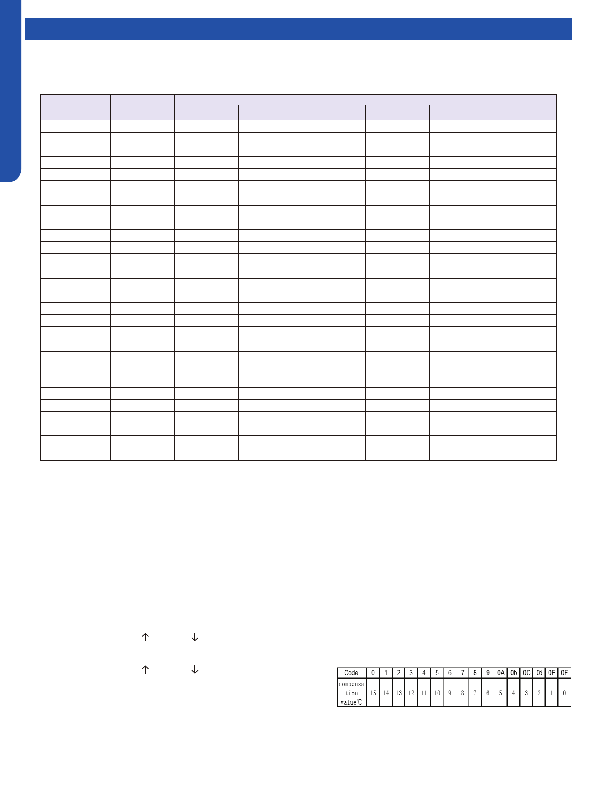
TROUBLESHOOTING & REFERENCES
J-4
ENGLISH
Special Functions
Temperature Compensation
This function allows you the capability to adjust the temperature compensation oset of any indoor unit. The adjusted value is
programmed into the EEPROM.
Guide 1
1. Install the grille assembly and connect the power cable.
2. Unplug the wired controller.
3. Connect power to the unit.
4. Press the ON/OFF button on the remote control (HBS-01).
5. (Ignore this step if the display temperature is already
O
C,) Press MENU/OF button to switch the display temperature to
O
C,
then press conrm.
6. Open the front cover of the remote controller, and press the LIGHT button 12 times in 7 seconds.
7. The panel will beep 4 times and display an “A”.
8. Press the LIGHT button once to conrm. The display will read “A0”.
9. Press the button TEMP.
or TEMP. until the display shows “A5”.
10. Press the LIGHT button once to conrm. The display will read “0b”.
11. Press the button TEMP. or TEMP. to scroll through the listed
Codes. Each code is associated with a corresponding compensation
value (see table below). For example, if you want make the
temperature invalid, scroll it to 0F.
12. Press the LIGHT button once to conrm. The display will read “A5”.
13. Press the ON/OFF button on the remote control to save the changes.
Series IDU
IDU PCB part number Controls Needed
Guide
Reference
Haier GEA Controller IR Reciever Wired Controller
3X3 Cassette AL24LP2VHA 0151800208 WJ26X23559 YR-HBS01 \ Unplug Chart 1
3X3 Cassette AL36LP2VHA 0151800208 WJ26X23559 YR-HBS01 \ Unplug Chart 1
3X3 Cassette AL48LP2VHA 0151800208 WJ26X23559 YR-HBS01 \ Unplug Chart 1
2X2 Cassette AB09SC2VH* 0151800208A WJ26X23785 YR-HBS01 \ Unplug Chart 3
2X2 Cassette AB12SC2VH* 0151800208A WJ26X23785 YR-HBS01 \ Unplug Chart 3
2X2 Cassette AB18SC2VH* 0151800208A WJ26X23785 YR-HBS01 \ Unplug Chart 3
Pro Duct AM24LP2VHA 0151800267 WJ26X23580 YR-HBS01 RE-02(CN21) Unplug Chart 2
Pro Duct AM36LP2VHA 0151800106E WJ26X23585 YR-HBS01 RE-02(CN29) Unplug Chart 2
Pro Duct AM48LP2VHA 0151800106E WJ26X23586 YR-HBS01 RE-02(CN29) Unplug Chart 2
Mid-Static Duct USYM09UCDSA 0151800580 WJ26X27175 YR-HG RE-02(CN29) Unplug Chart 4
Mid-Static Duct USYM12UCDSA 0151800580 WJ26X27175 YR-HG RE-02(CN29) Unplug Chart 4
Mid-Static Duct USYM18UCDSA 0151800580 WJ26X27175 YR-HG RE-02(CN29) Unplug Chart 4
Mid-Static Duct USYM24UCDSA 0151800580 WJ26X27175 YR-HG RE-02(CN29) Unplug Chart 4
Slim Duct AD07SL2VH* 0151800175A WJ26X23178 YR-HBS01 RE-02(CN29) Unplug Chart 2
Slim Duct AD09SL2VH* 0151800175A WJ26X23178 YR-HBS01 RE-02(CN29) Unplug Chart 2
Slim Duct AD12SL2VH* 0151800175A WJ26X23178 YR-HBS01 RE-02(CN29) Unplug Chart 2
Slim Duct AD18SL2VH* 0151800175A WJ26X23178 YR-HBS01 RE-02(CN29) Unplug Chart 2
Highwall AW07EH2VHA A0011001066 WJ26X25213 YR-HG \ \ Chart 4
Highwall AW09EH2VHA A0011001066 WJ26X25213 YR-HG \ \ Chart 4
Highwall AW12EH2VHA A0011001066 WJ26X25213 YR-HG \ \ Chart 4
Highwall AW18EH2VHA A0011007590 WJ26X25413 YR-HG \ \ Chart 4
Highwall AW07LC2VHB A0011800281CA WJ26X23928 YR-HG \ \ Chart 4
Highwall AW09LC2VHB A0011800281CA WJ26X23928 YR-HG \ \ Chart 4
Highwall AW12LC2VHB A0011800281CA WJ26X23928 YR-HG \ \ Chart 4
Highwall AW18LC2VHB A0011800281FA WJ26X23929 YR-HG \ \ Chart 4
Console USYF09UCDWA 0151800579 WJ26X27223 YR-HG \ \ Chart 4
Console USYF12UCDWA 0151800579 WJ26X27223 YR-HG \ \ Chart 4
Console USYF18UCDWA 0151800579 WJ26X27223 YR-HG \ \ Chart 4

TROUBLESHOOTING & REFERENCES
J-5
ENGLISH
Special Functions
Guide 2
1. Remove power to the unit and unplug the wired controller from the indoor unit PCB.
2. Connect the infrared remote signal receiver to indoor unit PCB.
0151800106E = socket CN29
0151800267 = socket CN21
3. Apply power to the unit.
4. Press the ON/OFF button on the remote control (HBS-01).
5. (Ignore this step if the display temperature is already
O
C,) Press MENU/
O
F button to switch the display temperature to
O
C,
then press conrm.
6. Set the remote controller for HEAT mode operation, and set the temperature to 24
O
C.
7. Aim the controller at the infrared signal receiver, and press the SLEEP button 7 times within 5 seconds. The remote signal
receiver will beep 2 times. The beeps indicates the set temperature compensation modication is available.
8. Aim the controller at the infrared signal receiver and adjust the temperature to X
O
C, then set the unit to OFF by pressing
the controller’s ON/OFF button. The remote signal receiver will beep 4 times. The beep indicates the set temperature
compensation has been set successfully. Note: X-24 is the compensation value. If X is set to 24, compensation is canceled (0). If
X = 25, compensation is 1
O
C. If X =26, compensation is 2
O
C. If X =22, compensation is -2
O
C, and so on.
9. To disable temperature compensation (0), set X to 24
10. Remove power and connect the wired controller.
11. Set the unit to OFF by pressing the button ON/OFF button. The setting will be in eect with the next ON time. This setting
will be saved in the EEPROM.
Guide 3
1. Remove power to the unit and unplug the wired controller from the indoor unit PCB.
2. Apply power to the unit.
3. Press the ON/OFF button on the remote control (HBS-01).
4. (Ignore this step if the display temperature is already
O
C,) Press MENU/
O
F button to switch the display temperature to
O
C,
then press conrm.
5. Set the remote controller for HEAT mode operation, and set the temperature to 24
O
C.
6. Aim the controller at the infrared signal receiver, and press the SLEEP button 7 times within 5 seconds. The remote signal
receiver will beep 2 times. The beeps indicates the set temperature compensation modication is available.
7. Aim the controller at the infrared signal receiver and adjust the temperature to X
O
C, then set the unit to OFF by pressing
the controller’s ON/OFF button. The remote signal receiver will beep 4 times. The beep indicates the set temperature
compensation has been set successfully. Note: X-24 is the compensation value. If X is set to 24, compensation is canceled (0). If
X = 25, compensation is 1
O
C. If X =26, compensation is 2
O
C. If X =22, compensation is -2
O
C, and so on.
8. Remove power and connect the wired controller.
9. Set the unit to OFF by pressing the button ON/OFF button. The setting will be in eect with the next ON time. This setting
will be saved in the EEPROM.
Guide 4
1. Apply power to the unit.
2. Set to Cooling Mode or Heating Mode
3. Set the temperature to 24
O
C.
4. Press the SLEEP button 7 times within 5 seconds. Indoor PCB will Beep 2 times to conrm.
5. 24
O
C will be the starting/reference point for the Temperature Compensation. Temperature Compensation can be adjusted
from -8
O
C to +6
O
C. Example: if you want to set the Temperature Compensation value by 4
O
C, then set the temperature to
28
O
C.
6. Once the desired value has been selected, turn OFF the unit via the YR-HG controller to save the compensation settings.
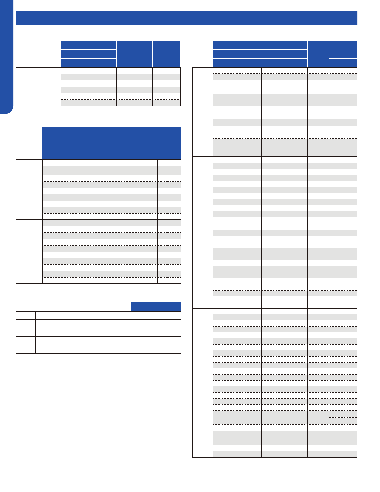
TROUBLESHOOTING & REFERENCES
J-6
ENGLISH
Topic TitleMatching Tables
2U18MS2VHB / 2U20EH2VHA
Combinations
Total Capacity
Required
Adapter
Port B Port A
1/4" x 3/8" 1/4" x 3/8"
Two
Zone
7 7 14K -
9 7 16K -
9 9 18K -
12 7 19K -
12 9 21K -
12 12 24K -
3U24MS2VHB / 3U24EH2VHA
Combinations
Total
Capacity
Required
Adapter
Port C Port B Port A
MS: 1/4" x 3/8"
EH: 1/4" x 1/2"
1/4" x 3/8" 1/4" x 3/8" MS EH
Two Zone
7 7 - - - 14K - E
9 7 - - - 16K - E
9 9 - - - 18K - E
12 7 - - - 19K - E
12 9 - - - 21K - E
12 12 - - - 24K - E
18 7 - - - 25K D -
18 9 - - - 27K D -
18 12 - - - 30K D -
Three
Zone
7 7 7 21K - E
9 7 7 23K - E
9 9 7 25K - E
12 7 7 26K - E
9 9 9 27K - E
12 9 7 28K - E
12 9 9 30K - E
12 12 7 31K* - E
18 7 7 32K* D -
12 12 9 33K* - E
4U36MS2VHB/ 4U36EH2VHA
Combinations
Total
Capacity
Required
Adapter
Port D Port C Port B Port A
1/4" x 1/2" 1/4" x 3/8" 1/4" x 3/8" 1/4" x 3/8" MS EH
Two
Zone
18 9 - - - - - - 27K -
18 12 - - - - - - 30K -
24 7 - - - - - - 31K
C
A
24 9 - - - - - - 33K
C
A
24 12 - - - - - - 36K
C
A
18 18 - - - - - - 36K D
18 24 - - - - - - 42K
A
B
24 24 - - - - - - 48K*
B
C
A (x2)
Three
Zone
9 9 9 - - - 27K E -
12 9 7 - - - 28K E -
12 9 9 - - - 30K E -
12 12 7 - - - 31K E -
18 7 7 - - - 32K -
12 12 9 - - - 33K E -
18 9 7 - - - 34K -
18 9 9 - - - 36K -
12 12 12 - - - 36K E -
18 12 7 - - - 37K -
24 7 7 - - - 38K
C
A
18 12 9 - - - 39K -
24 9 7 - - - 40K
C
A
24 9 9 - - - 42K
C
A
18 12 12 - - - 42K -
24 12 7 - - - 43K
C
A
24 12 9 - - - 45K
C
A
18 18 12 - - - 48K* D
24 12 12 - - - 48K*
C
A
Four
Zone
7 7 7 7 28K E
9 7 7 7 30K E
9 9 7 7 32K E
12 7 7 7 33K E
9 9 9 7 34K E
12 9 7 7 35K E
9 9 9 9 36K E
12 9 9 7 37K E
12 12 7 7 38K E
12 9 9 9 39K E
18 7 7 7 39K -
12 12 9 7 40K E
18 9 7 7 41K -
12 12 9 9 42K E
12 12 12 7 43K E
18 9 9 7 43K -
18 12 7 7 44K -
24 7 7 7 45K
C
A
12 12 12 9 45K E
24 9 7 7 47K*
C
A
12 12 12 12 48K* E
18 12 9 9 48K* -
*ALL INDOOR UNITS MUST BE FLEXFIT.
*ALL INDOOR UNITS MUST BE FLEXFIT.
Adapters
GEA Part #GEA Part #
A 1/4” to 3/8” (Liquid line for ports C & D) WJ01X23925
B 3/8” to 5/8” (Vapor line for port C) WJ01X23924
C 1/2” to 5/8” (Vapor line for port D) WJ01X23932
D 3/8” to 1/2” (Vapor line for port C) WJ01X26853
E 1/2” to 3/8” (Vapor line for port C OR D) WJ01X26854
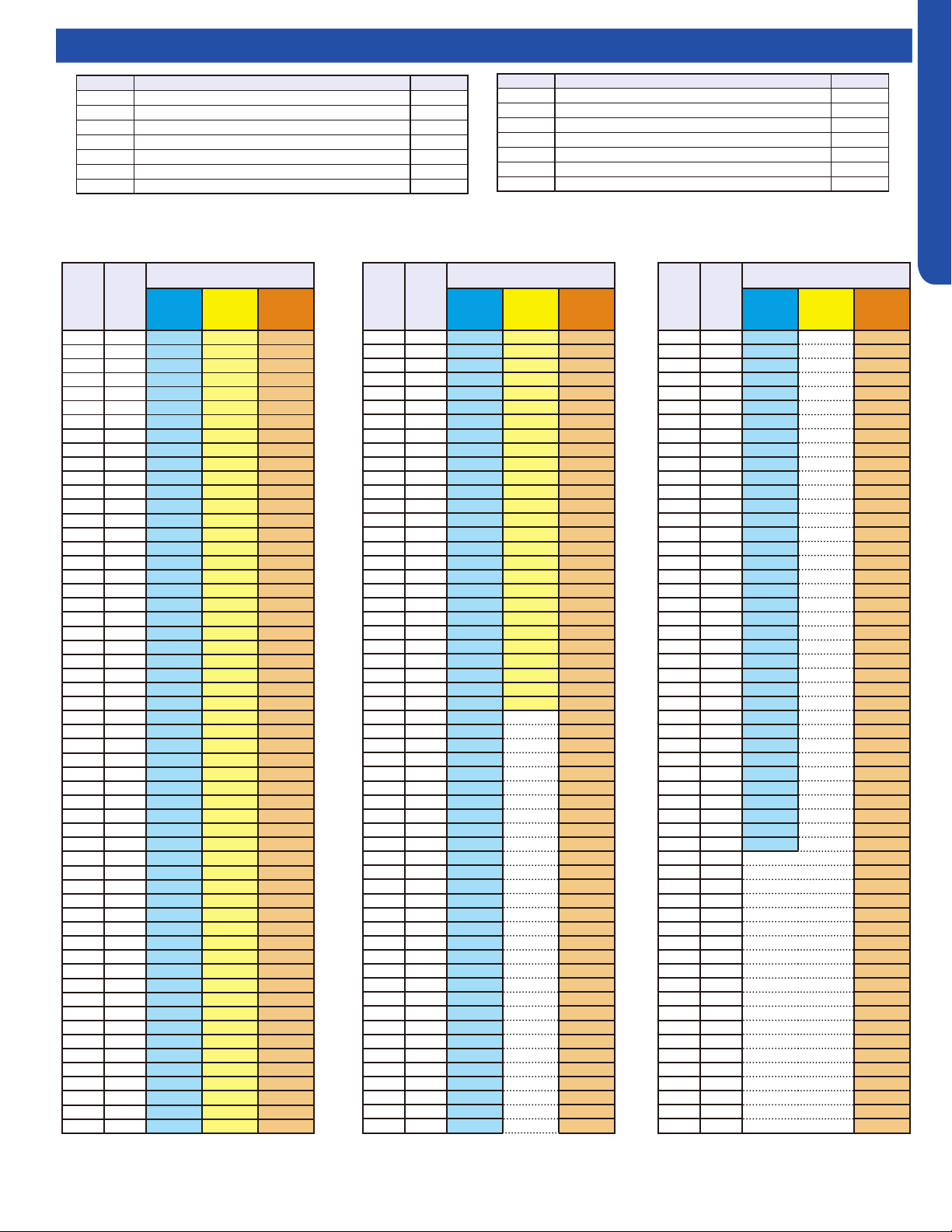
TROUBLESHOOTING & REFERENCES
J-7
ENGLISH
Topic TitleResistance Chart / Sensor Denitions
Abbr. Definition Type
tAo Temperature of outdoor ambient 10K
tc Temperature of outdoor condenser 10K
td Temperature of outdoor discharge 50K
tE Temperature of outdoor defrost 10K
tS Temperature of outdoor suction 10K
tdr Temperature of compressor driver module 10K
Idr Current of the compressor 10K
Abbr. Definition Type
tAI Temperature of indoor ambient 10K
TCI Temperature of indoor condenser 10K
Toci Hot Gas Leaving the 4-Way Valve 10K
Tc2 EEV Liquid Sensor 10K
Tc1 EEV Gas Sensor 10K
Tm Module Temp Sensor 10K
TAI Temperature of indoor ambient (9K/12K Tempo & All CAC) 23K
10K Sensors: Ambient (all except ducted, cassette, and 9K-12K Tempo) suction, gas, defrost, and pipe sensors.
23K Sensors: Ambient sensors for ducted, cassette, and 9K-12K Tempo
50K Sensors: Discharge sensors
°F °C
Normal (KΩ)
10K
SENSORS
23K
SENSORS
50K
SENSORS
-22 -30 147.95 513.115 12061.74
-20.2 -29 139.56 478.894 11267.87
-18.4 -28 131.70 447.408 10531.37
-16.6 -27 124.34 418.379 9847.72
-14.8 -26 117.44 391.564 9212.81
-13 -25 110.96 366.751 8622.85
-11.2 -24 104.89 343.754 8074.38
-9.4 -23 99.19 322.407 7564.22
-7.6 -22 93.83 302.567 7089.47
-5.8 -21 88.80 284.105 6647.45
-4 -20 84.07 266.905 6235.71
-2.2 -19 79.62 250.866 5851.99
-0.4 -18 75.44 235.895 5494.21
1.4 -17 71.50 221.911 5160.46
3.2 -16 67.79 208.838 4849.00
5 -15 64.30 196.609 4558.19
6.8 -14 61.01 185.163 4286.55
8.6 -13 57.91 174.443 4032.71
10.4 -12 54.99 164.399 3795.39
12.2 -11 52.23 154.983 3573.43
14 -10 49.62 146.153 3365.73
15.8 -9 47.17 137.87 3171.31
17.6 -8 44.85 130.096 2989.25
19.4 -7 42.65 122.799 2818.67
21.2 -6 40.58 115.946 2658.81
23 -5 38.62 109.51 2508.91
24.8 -4 36.77 103.462 2368.32
26.6 -3 35.01 97.779 2236.39
28.4 -2 33.36 92.437 2112.55
30.2 -1 31.78 87.415 1996.25
32 0 30.30 82.691 1887.00
33.8 1 28.89 78.248 1784.33
35.6 2 27.55 74.067 1687.81
37.4 3 26.29 70.133 1597.04
39.2 4 25.09 66.43 1511.65
41 5 23.95 62.943 1431.28
42.8 6 22.87 59.659 1355.62
44.6 7 21.84 56.566 1284.36
46.4 8 20.87 53.651 1217.23
48.2 9 19.94 50.904 1153.96
50 10 19.06 48.314 1094.32
51.8 11 18.23 45.872 1038.07
53.6 12 17.43 43.569 985.01
55.4 13 16.68 41.395 934.94
57.2 14 15.96 39.343 887.68
59 15 15.28 37.406 843.05
60.8 16 14.63 35.577 800.89
62.6 17 14.01 33.848 761.06
64.4 18 13.42 32.215 723.41
66.2 19 12.86 30.671 687.82
68 20 12.32 29.21 654.16
69.8 21 11.81 27.828 622.32
71.6 22 11.33 26.521 592.18
73.4 23 10.86 25.283 563.66
75.2 24 10.42 24.111 536.65
77 25 10.00 23 511.08
78.8 26 9.60 21.947 486.94
°F °C
Normal (KΩ)
10K
SENSORS
23K
SENSORS
50K
SENSORS
80.6 27 9.21 20.949 464.05
82.4 28 8.85 20.003 442.35
84.2 29 8.50 19.104 421.77
86 30 8.16 18.252 402.24
87.8 31 7.84 17.442 383.72
89.6 32 7.54 16.674 366.13
91.4 33 7.25 15.943 349.43
93.2 34 6.97 15.249 333.58
95 35 6.70 14.588 318.52
96.8 36 6.45 13.96 304.22
98.6 37 6.20 13.362 290.62
100.4 38 5.97 12.794 277.70
102.2 39 5.75 12.252 265.41
104 40 5.53 11.736 253.73
105.8 41 5.33 11.244 242.62
107.6 42 5.13 10.776 232.04
109.4 43 4.94 10.329 221.98
111.2 44 4.76 9.904 212.41
113 45 4.59 9.497 203.29
114.8 46 4.43 9.11 194.61
116.6 47 4.27 8.74 186.34
118.4 48 4.11 8.387 178.46
120.2 49 3.97 8.05 170.95
122 50 3.83 7.728 163.80
123.8 51 3.69 7.421 156.97
125.6 52 3.57 7.127 150.47
127.4 53 3.44 6.846 144.26
129.2 54 3.32 138.35
131 55 3.21 132.70
132.8 56 3.10 127.31
134.6 57 2.99 122.16
136.4 58 2.89 117.25
138.2 59 2.79 112.56
140 60 2.70 108.08
141.8 61 2.61 103.80
143.6 62 2.52 99.70
145.4 63 2.44 95.79
147.2 64 2.36 92.06
149 65 2.28 88.48
150.8 66 2.21 85.06
152.6 67 2.14 81.79
154.4 68 2.07 78.66
156.2 69 2.00 75.67
158 70 1.94 72.80
159.8 71 1.88 70.06
161.6 72 1.82 67.43
163.4 73 1.76 64.91
165.2 74 1.71 62.50
167 75 1.65 60.19
168.8 76 1.60 57.98
170.6 77 1.55 55.86
172.4 78 1.51 53.82
174.2 79 1.46 51.87
176 80 1.41 50.00
177.8 81 1.37 48.21
179.6 82 1.33 46.48
181.4 83 1.29 44.83
°F °C
Normal (KΩ)
10K
SENSORS
23K
SENSORS
50K
SENSORS
183.2 84 1.25 43.25
185 85 1.22 41.72
186.8 86 1.18 40.26
188.6 87 1.14 38.85
190.4 88 1.11 37.50
192.2 89 1.08 36.21
194 90 1.05 34.96
195.8 91 1.02 33.77
197.6 92 0.99 32.62
199.4 93 0.96 31.51
201.2 94 0.93 30.45
203 95 0.91 29.42
204.8 96 0.88 28.44
206.6 97 0.86 27.50
208.4 98 0.83 26.59
210.2 99 0.81 25.71
212 100 0.79 24.87
213.8 101 0.76 24.06
215.6 102 0.74 23.28
217.4 103 0.72 22.52
219.2 104 0.70 21.80
221 105 0.68 21.10
222.8 106 0.67 20.43
224.6 107 0.65 19.78
226.4 108 0.63 19.16
228.2 109 0.61 18.56
230 110 0.60 17.98
231.8 111 0.58 17.42
233.6 112 0.57 16.88
235.4 113 0.55 16.36
237.2 114 0.54 15.85
239 115 0.52 15.37
240.8 116 0.51 14.90
242.6 117 0.50 14.45
244.4 118 0.48 14.01
246.2 119 0.47 13.59
248 120 0.46 13.19
249.8 121 12.80
251.6 122 12.42
253.4 123 12.05
255.2 124 11.70
257 125 11.35
258.8 126 11.02
260.6 127 10.70
262.4 128 10.40
264.2 129 10.10
266 130 9.81
267.8 131 9.53
269.6 132 9.26
271.4 133 9.00
273.2 134 8.74
275 135 8.50
276.8 136 8.26
278.6 137 8.03
280.4 138 7.81
282.2 139 7.60
284 140 7.39
TROUBLESHOOTING & REFERENCES
J-8
ENGLISH
Topic TitleResistance Values
Cassette Louver Motor
Red
Orange 200 Ω
Yellow 200 Ω
Blue 200 Ω
Violet 200 Ω
Ducted Horizontal & Vertical Louver Motors
Red
Blue
200 Ω
Violet 200 Ω
Yellow 200 Ω
Orange 200 Ω
Highwall Horizontal Louver Motor (FlexFit)
Blue Violet Yellow Orange Red
Blue
- 393 Ω 394 Ω 395 Ω 196 Ω
Violet - - 396 Ω 397 Ω 198 Ω
Yellow - - - 398 Ω 199 Ω
Orange - - - - 200 Ω
Red - - - - -
Highwall Vertical Louver Motor (FlexFit)
Blue Violet Yellow Orange Red
Blue
- 383 Ω 388 Ω 390 Ω 195 Ω
Violet - - 381 Ω 385 Ω 189 Ω
Yellow - - - 388 Ω 193 Ω
Orange - - - - 196 Ω
Red - - - - -
EEV (6-pin, 6 wire)
White Yellow Orange Blue Brown Red
White - OL 92 Ω OL 46 Ω OL
Yellow - - OL 92 Ω OL 46 Ω
Orange - - - OL 46 Ω OL
Blue - - - - OL 46 Ω
Brown - - - - - OL
Red - - - - - -
EEV (6-pin, 5 wire)
White Yellow Orange Blue X Red
White - 92 Ω 92 Ω 92 Ω - 46 Ω
Yellow - - 92 Ω 92 Ω - 46 Ω
Orange - - - 92 Ω - 46 Ω
Blue - - - - - 46 Ω
X - - - - - -
Red - - - - - -
Highwall Horizontal Louver Motor
Orange Yellow Pink Blue Grey
Red
193 Ω 189.5 Ω 185.4 Ω 191.5 Ω -
Orange - 381.6 Ω 377.4 Ω 383.3 Ω 47 Ω
Yellow - - 373.9 Ω 379.9 Ω -
Pink - - - 375.8 Ω 46.8 Ω
Blue - - - - -
Grey - - - - -
Highwall Vertical Louver Motor
Yellow Orange Blue Red Grey
White - 92.6 Ω - 47 Ω -
Yellow - - 93.1 Ω - 47 Ω
Orange - - - 46.5 Ω -
Blue - - - - 46.8 Ω
Red - - - - -
Grey - - - - -
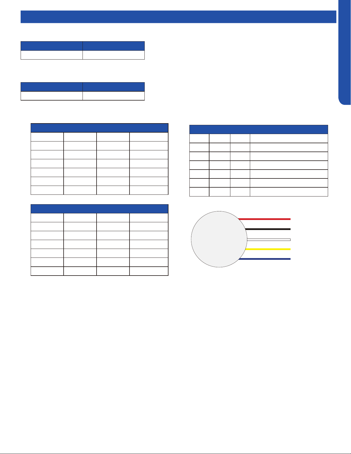
TROUBLESHOOTING & REFERENCES
J-9
ENGLISH
Topic TitleComponent Ratings
VDC Outputs to DC Fan Motor (VDC)
PIN # RED Probe Black Probe Value
6 Vdc GND 300~380VDC
5 Blank Blank Blank
4 GND GND GND
3 Vcc GND 15 ±1.5VDC
2 Vsp GND 2~6.5VDC
1 FG GND 2~9VDC
DC Fan Motor Resistance Values (Ω)
PIN # RED Probe Black Probe Value
6 Vdc GND ≥1MΩ
5 Blank Blank Blank
4 GND GND GND
3 Vcc GND ≥1MΩ
2 Vsp GND ≥135KΩ
1 FG GND ≥1MΩ
DC Fan Motor Pin Identication
PIN # Color Abbr. Denition
1 Blue FG Revolution Pulse Output
2 Yellow Vsp Speed Control Voltage Input
3 White Vcc Control Power Voltage Input
4 Black GND Ground
5 Blank Blank Blank
6 Red Vdc Motor Driver Voltage Input
DC Motor
+310 VDC
DC Ground
+15 VDC
Signal
Feedback
Red
Black
White
Yellow
Blue
Fan Motors
Ohms
VAC
2.1K 208-230
4-Way Valve
Ohms
VAC
0.28K - 0.379K 208-230
Basepan Heater

TROUBLESHOOTING & REFERENCES
J-10
ENGLISH
Refrigeration Diagrams
Comp-
●
ressor
Discharge temp.
sensor
Oil
separator
Capillary tube
Ø2.7*Ø1.0*1400
High pressure
switch
4-way valve
Pipe sensor
●
Toci
Suction temp.
sensor
Low pressure
switch
Accumulator
Gas service valve
Outdoor
heat
exchanger
temp.
sensor
FAN-OUT
●
Outdoor
ambient
temperature
sensor
Defrost
sensor
Distributor
Strainer
EEV O
Receiver
Liquid service valve
5/8
3/8
Unit A liquid pipe temp. sensor TC2
Strainer
EEV A
Indoor unit A
Unit B liquid pipe temp. sensor TC2
Strainer
EEV B
Indoor unit B
Unit A gas pipe temp. sensor TC1
Unit B gas pipe temp. sensorTC1
Indoor unit A
Indoor unit B
4-way valve coil:
OFF
ON
Refrigerant flow in cooling
Refrigerant flow in heating
FAN-IN
Indoor
ambient
temperature
sensor
Indoor
heat
exchanger
temp.
sensor
2U20EH2VHA
3U24EH2VHA
Comp-
ressor
D
ischarge temp.
●
sensor
Oil
separator
Capillary tube
Ø2.7*Ø1.0*1400
High pressure
switch
4-way valve
Pipe sensor
Toci
Suction temp.
sensor Ts
Low pressure
switch
Accumulator
Gas service valve
Outdoor
heat
exchanger
temp.
sensor
FAN-OUT
Outdoor
ambient
temperature
sensor Ta
Defrost
sensor Td
Distributor
Strainer
EEV O
Receiver
Liquid service valve
5/8
3/8
Unit A liquid pipe temp. sensor Tc2
Strainer
EEV A
Indoor unit A
Unit B liquid pipe temp. sensorTc2
Strainer
EEV B
Indoor unit B
Unit C liquid pipe temp. sensor Tc2
Strainer
EEV C
Indoor unit C
Unit A gas pipe temp. sensor Tc1
Unit
B gas pipe temp.
sensor Tc1
Unit C gas pipe temp. sensor Tc1
Indoor unit A
Indoor unit B
Indoor unit C
4-way valve coil:
OFF
ON
Refrigerant flow in cooling
Refrigerant flow in heating
FAN-IN
Indoor
ambient
temperature
sensor
Indoor
heat
exchanger
temp.
sensor

TROUBLESHOOTING & REFERENCES
J-11
ENGLISH
Refrigeration Diagrams
4U36EH2VHA
Comp-
ressor
D
ischarge temp.
●
sensor
Oil
separator
Capillary tube
Ø2.7*Ø1.0*1400
High pressure
switch
4-way valve
Pipe sensor
Toci
Suction temp.
sensor Ts
Low pressure
switch
Accumulator
Gas service valve
Outdoor
heat
exchanger
temp.
sensor
FAN-OUT
Outdoor
ambient
temperature
sensor Ta
Defrost
sensor Td
Distributor
Strainer
EEV O
Receiver
Liquid service valve
5/8
3/8
Unit A liquid pipe temp. sensor Tc2
Strainer
EEV A
Indoor unit A
Unit B liquid pipe temp. sensorTc2
Strainer
EEV B
Indoor unit B
Unit C liquid pipe temp. sensor Tc2
Strainer
EEV C
Indoor unit C
Unit A gas pipe temp. sensor Tc1
Unit
B gas pipe temp.
sensor Tc1
Unit C gas pipe temp. sensor Tc1
Indoor unit A
Indoor unit B
Indoor unit C
4-way valve coil:
OFF
ON
Refrigerant flow in cooling
Refrigerant flow in heating
FAN-IN
Indoor
ambient
temperature
sensor
Indoor
heat
exchanger
temp.
sensor
Unit D liquid pipe temp. sensor Tc2
Strainer
EEV D
Indoor unit D
Indoor unit D
Unit D gas pipe temp. sensor Tc1
4U36EH2VHA
TROUBLESHOOTING & REFERENCES
J-12
ENGLISH
Topic TitleMaster Error Code Chart
HIGHWALL CONSOLE COMPACT CASSETTE
Outdoor
Pro-Series
LED Display
(CAC)
Outdoor
Multi-Zone
LED Display
(CAC)
Outdoor
Single-Zone
LED1 Flash
(RAC)
FAULT DESCRIPTION
Digital
Display
Digital
Display
Panel LED Flash or
ID PCB LED Flash
Yellow Timer LED
(PCB LED5)
Green Run LED
(PCB LED1)
1
1 1 Outdoor EEPROM failure F12 F12 2 1
2
2 2 IPM overcurrent or short circuit F1 F1 2 2
/
/ 3 Outdoor alternating current, over current protection F22 F22 2 3
3
/ / Compressor over current during deceleration / / / /
4
4 4 Communication failure between the IPM and outdoor PCB F3 F3 2 4
5
5 5 Module operated overload (compressor overload protection) F20* F20* 2 5
6
6 6 Module low or high voltage F19* F19* 2 6
7
/ 7 Compressor current sampling circuit fault F27 F27 2 7
8
8 8 Overheat protection for discharge temperature F4 F4 2 8
9
9 9 Malfunction of the DC fan motor F8* F8* 2 9
10
10 10 Malfunction of defrost temperature sensor F21 F21 3 0
11
11 11 Suction temperature sensor failure F7 F7 3 1
12
12 12 Ambient temperature sensor failure F6 F6 3 2
13
13 13 Discharge temperature sensor failure F25 F25 3 3
/
/ 14 High outdoor suction temperature F30* F30* 3 4
14
/ / PFC circuit loop voltage / / / /
15
15 15 Communication failure between the indoor & outdoor unit E7 E7 3 5
16
16 16 Lack of refrigerant or discharging F13* F13* 3 6
17
17 17 4-way valve switching failure F14* F14* 3 7
18
18 18 Loss of synchronism detection F11 F11 3 8
/
/ 19 Position detection circuit fault of compressor F28 F28 3 9
19
/ / Low DC or AC voltage / / / /
/
/ 20 Terminal block temp too high F15* F15* 4 0
20
20 / Indoor thermal overload E9 / 4 0
/
21 21 Indoor unit overload protection, heating mode only. E9* / 4 1
/
21 / Indoor coil frosted E5 / 4 1
/
/ 22 Indoor anti-frosting protection E5* / 4 2
22
/ / PFC circuit loop overcurrent / / / /
/
/ 23 Indoor coil temperature (abnormal reading) / / / /
23
23 / Module thermal overload F5* F5* 4 3
24
24 24 Compressor start failure, over-current F2* F2* 4 4
25
25 25 Phase current protection (IPM) F23* F23 4 5
/
26 / MCU reset F9 F9 4 6
26
/ / IPM power supply phase loss (3-phase) / /
27
27 27 Module current detect circuit malfunction F24 F24 4 7
28
/ / Wiring error: Compressor to IPM / / / /
* Hidden indoor error code. LED1 will flash outdoors, but no error will appear on indoor unit display.
To view error code on indoor display, press and hold the Emergency button for 15 seconds.
TROUBLESHOOTING & REFERENCES
J-13
ENGLISH
LARGE CASSETTE DUCTED WIRED CONTROLLER
Panel LED Flash or
ID PCB LED Flash
Panel
Display
(PB*****)
HIGH STATIC
MID-STATIC DUCT
(MSP)
SLIM DUCT
YRE-17A
QACT17A
YRE-16B
Yellow Timer LED
(PCB LED4)
Green Run LED
(PCB LED1)
LED4
(Yellow)
LED3
(Green)
LED4 LED3
LED4
(Yellow)
LED3
(Green)
2 1 15 2 1 2 1 2 1 15 21
2 2 16 2 2 2 2 2 2 16 22
/ / / / / / / / / 17 23
2 3 17 2 3 2 3 2 3 17 23
2 4 18 2 4 2 4 2 4 18 24
2 5 19 2 5 2 5 2 5 19 25
2 6 1A 2 6 2 6 2 6 1A 26
2 7 1B 2 7 2 7 2 7 1B 27
2 8 1C 2 8 2 8 2 8 1C 28
2 9 1D 2 9 2 9 2 9 1D 29
3 0 1E 3 0 3 0 3 0 1E 30
3 1 1F 3 1 3 1 3 1 1F 31
3 2 20 3 2 3 2 3 2 20 32
3 3 21 3 3 3 3 3 3 21 33
/ / / / / / / / / 22 34
3 4 22 3 4 3 4 3 4 22 34
3 5 23 3 5 3 5 3 5 23 35
3 6 24 3 6 3 6 3 6 24 36
3 7 25 3 7 3 7 3 7 25 37
3 8 26 3 8 3 8 3 8 26 38
/ / / / / / / / / 27 39
3 9 27 3 9 3 9 3 9 27 39
/ / / / / / / / / 28 40
4 0 28 4 0 4 0 4 0 28 40
/ / / / / / / / / 29 41
4 1 29 4 1 4 1 4 1 29 41
/ / / / / / / / / 2A 42
4 2 2A 4 2 4 2 4 2 2A 42
/ / / / / / / / / / /
4 3 2B 4 3 4 3 4 3 2B 43
4 4 2C 4 4 4 4 4 4 2C 44
4 5 2D 4 5 4 5 4 5 2D 45
4 6 2E 4 6 4 6 4 6 2E 46
/ / / 2F 47
4 7 2F 4 7 4 7 4 7 2F 47
/ / / / / / / / / / /
Master Error Code Chart
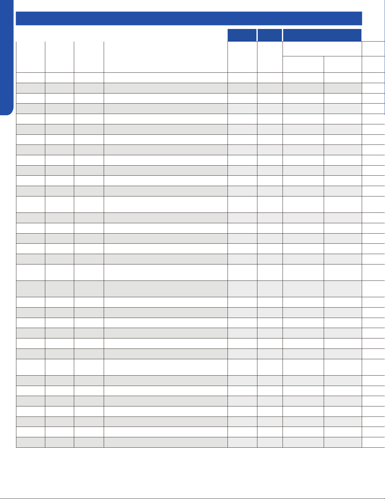
TROUBLESHOOTING & REFERENCES
J-14
ENGLISH
Master Error Code Chart
HIGHWALL CONSOLE COMPACT CASSETTE
Outdoor
Pro-Series
LED Display
(CAC)
Outdoor
Multi-Zone
LED Display
(CAC)
Outdoor
Single-Zone
LED1 Flash
(RAC)
FAULT DESCRIPTION
Digital
Display
Digital
Display
Panel LED Flash or
ID PCB LED Flash
Yellow Timer LED
(PCB LED5)
Green Run LED
(PCB LED1)
/
/ 28 Low refrigerant flow. Lockout. / / / /
/
28 / Liquid pipe sensor failure: Circuit A F10 F10 4 8
/
29 / Liquid pipe sensor failure: Circuit B F16 F16 4 9
/
30 / Liquid pipe sensor failure: Circuit C F17 F17 5 0
/
31 / Liquid pipe sensor failure: Circuit D F18 F18 5 1
/
32 / Gas pipe sensor failure: Circuit A F29 F29 5 2
/
33 / Gas pipe sensor failure: Circuit B F30 F30 5 3
/
34 / Gas pipe sensor failure: Circuit C F31 F31 5 4
/
35 / Gas pipe sensor failure: Circuit D F32 F32 5 5
/
36 / Gas pipe sensor failure: Circuit E F26 F26 5 6
/
/ 37 Outdoor pipe temperature protection in cooling mode F34 F34 5 7
37
/ / Compressor overcurrent detected by IPM / / / /
38
38 /
Malfunction of module temperature sensor momentary
power failure detection
F35 F35 5 8
39
39 39 Malfunction of condensing temperature sensor F36 F36 5 9
/
40 / Liquid pipe sensor failure - Circuit E F33 F33 6 0
/
41 / Toci temperature sensor failure F38 F38 6 1
42
42 / High Pressure switch open F39 F39 6 2
43
43 / Low Pressure switch open F40 F40 6 3
44
44 /
System high pressure protection: Overcharged, high
condensing temperature or malfunction of fan motor.
F41 F41 6 4
45
45 /
System low pressure protection: Undercharged, low
defrosting temperature, or malfunction of fan motor.
F42 F42 6 5
/
/ 46 Incorrect match between indoor & outdoor F43 F43 6 6
/
L0 / OAT less than -22°F (-30°C) / / / /
/
/ / Indoor ambient temperature sensor failure E1 E1 0 1
/
/ / Indoor coil temperature sensor failure E2 E2 0 2
/
/ / Indoor PCB EEPROM failure E4 E4 0 4
/
/ / Communication fault between the indoor and outdoor unit / / 0 7
/
/ /
Communication fault between the controller and Indoor
unit
/ E8 0 8
/
/ / DC voltage of the fan motor driver too high or too low / / / /
/
/ / Fan motor driver over 95°F (35°C) / / / /
/
/ / Indoor fan motor out of step / / / /
/
/ / Drain system malfunction / E12 0 12
/
/ / Zero cross signal detected wrong / E13 / C1 0 13
/
/ / Indoor fan motor malfunction E14* E14 0 14
/
/ / Indoor fan motor overcurrent / / / /
* Hidden indoor error code. LED1 will flash outdoors, but no error will appear on indoor unit display.
To view error code on indoor display, press and hold the Emergency button for 15 seconds.
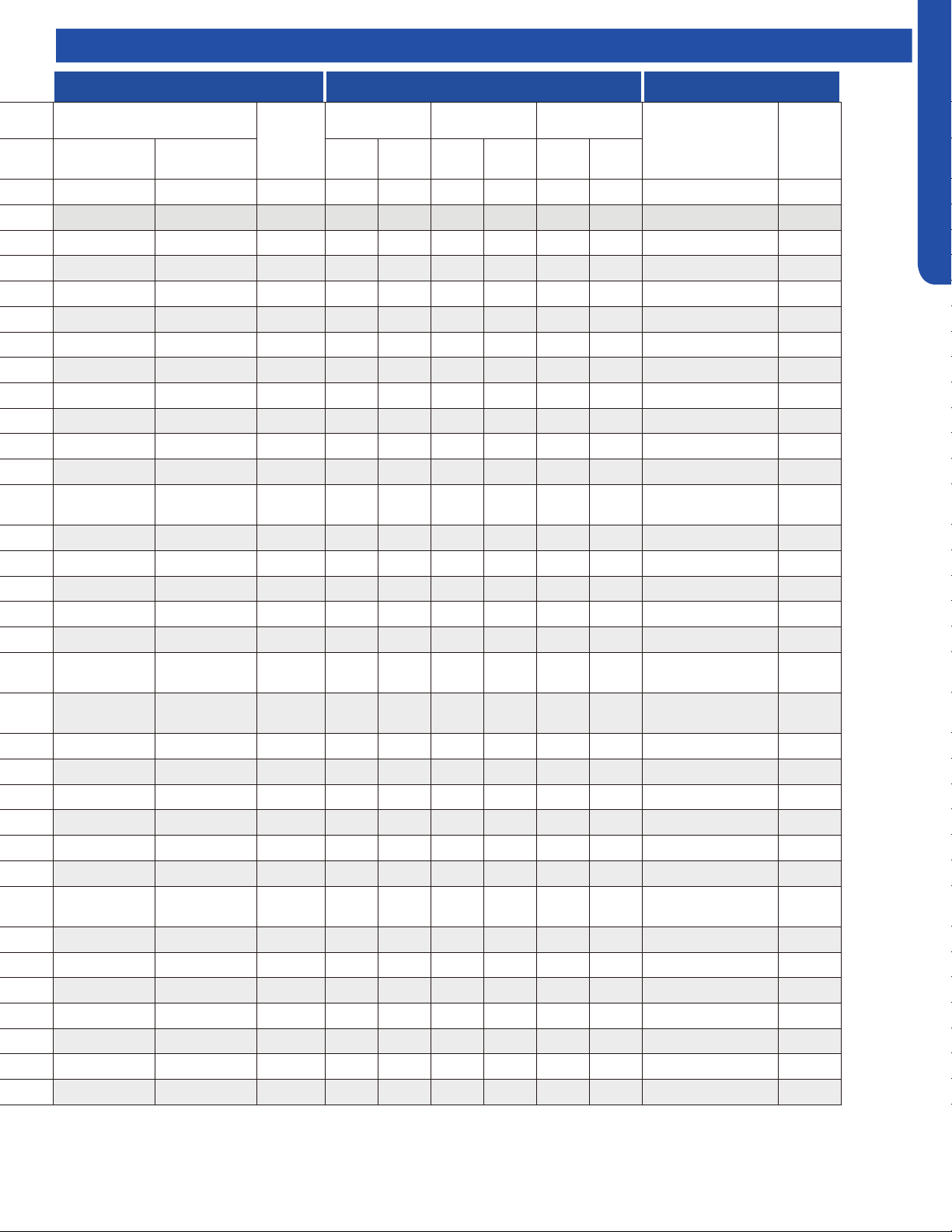
TROUBLESHOOTING & REFERENCES
J-15
ENGLISH
LARGE CASSETTE DUCTED WIRED CONTROLLER
Panel LED Flash or
ID PCB LED Flash
Panel
Display
(PB*****)
HIGH STATIC
MID-STATIC DUCT
(MSP)
SLIM DUCT
YRE-17A
QACT17A
YRE-16B
Yellow Timer LED
(PCB LED4)
Green Run LED
(PCB LED1)
LED4
(Yellow)
LED3
(Green)
LED4 LED3
LED4
(Yellow)
LED3
(Green)
/ / / / / / / / / / /
4 8 30 4 8 4 8 4 8 30 48
4 9 31 4 9 4 9 4 9 31 49
5 0 32 5 0 5 0 5 0 32 50
5 1 33 5 1 5 1 5 1 33 51
5 2 34 5 2 5 2 5 2 34 52
5 3 35 5 3 5 3 5 3 35 53
5 4 36 5 4 5 4 5 4 36 54
5 5 37 5 5 5 5 5 5 37 55
5 6 38 5 6 5 6 5 6 38 56
/ / / / / / / / / 39 57
5 7 39 5 7 5 7 5 7 39 57
5 8 3A 5 8 5 8 5 8 3A 58
5 9 3B 5 9 5 9 5 9 3B 59
6 0 3C 6 0 6 0 6 0 3C 60
6 1 3D 6 1 6 1 6 1 3D 61
6 2 3E 6 2 6 2 6 2 3E 62
6 3 3F 6 3 6 3 6 3 3F 63
6 4 40 6 4 6 4 6 4 40 64
6 5 41 6 5 6 5 6 5 41 65
/ / / / / / / / / 42 66
/ / / / / / / / / / /
0 1 01 0 1 0 1 0 1 01 01
0 2 02 0 2 0 2 0 2 02 02
0 4 04 0 4 0 4 0 4 04 04
0 7 07 0 7 0 7 0 7 07 07
0 8 08 0 8 0 8 0 8
Flashing 07 (YR-E17) /
Flashing ! (QACT17A)
/
/ / / 0 17 / / 0 17 11 17
/ / / 0 18 / / 0 18 12 18
/ / / 0 19 / / 0 19 13 19
0 12 0C 0 12 0 12 0 12 0C 12
0 13 0D 0 13 0 13 0 13 0D 13
0 14 0E 0 14 0 14 0 14 0E 14
/ / / 0 15 / / 0 15 0F 15
Master Error Code Chart

TROUBLESHOOTING & REFERENCES
J-16
ENGLISH
Outdoor Unit Error Codes
Error Code 10
This code indicates an electrical failure of the sensor that is
used to sense the temperature of the outdoor coil during
defrost. This sensor is connected to the PCB via a connection
at Plug CN-14.
Error Code 11
This code indicates an electrical failure of the sensor that is
used to sense the temperature of the suction gas that enters
the compressor. The sensor is connected to the PCB via two
wires at Plug CN-14.
Error Code 12
This code indicates an electrical failure of the sensor that is
used to sense the temperature of the outdoor air. The sensor
is connected to the PCB via two wires at Plug CN-14.
Error Code 13
This code indicates an electrical failure of the sensor that is
used to sense the temperature of the compressor hot gas
discharge line. The sensor is connected to the PCB via two
wires at Plug CN-14.
Temperature Sensor Error Codes
The easiest problems to solve will involve codes that are related to potential failure of temperature sensors. Common problems
may include loose connections, open or shorted, and out of calibration. Checking the condition of the sensors requires a
temperature probe and an ohmmeter.
The Reference Section of this manual contains temperature resistance tables that can be used to check the calibration of the
sensors. The measured resistance must be within the tolerances located in the tables.
There are 16 potential Error Codes that can be generated by the PCB to indicate a failure of an outdoor unit temperature sensor.
When the system generates an error code, it will be displayed on the Service Monitor Board, the number of ashes on the PCB,
and also on the indoor unit display panel.
Error Code 28-36
These codes indicate a failure of either a Liquid or Gas
Temperature Sensor that is part of either the A, B, C, or
D indoor unit EEV circuit. Refer to the outdoor unit Error
Code Decal for specic identication of the malfunctioning
temperature sensor. These sensors connect to the PCB at
connection plugs near the center of the circuit board. (Note
that if the sensor has failed, and there is an unused port on
the unit available, the sensor from the unused port can be
used to temporarily x the problem.)
Error Code 38
This code indicates a potential failure of the IPM temperature
sensor. This sensor connects to the IPM via Plug CN-8. This
sensor is mounted near the heat sink.
Error Code 39
This code indicates an electrical failure of the sensor that is
used to sense the condensing temperature of the outdoor
coil. The sensor is connected to the PCB via two wires at Plug
CN-14.
Error Code 41
This code indicates an electrical failure of the 'Toci' sensor,
which ensures there is no drop in hot gas temperature
through the 4-way valve. The sensor is connected to the PCB
via two wires at Plug CN-7.
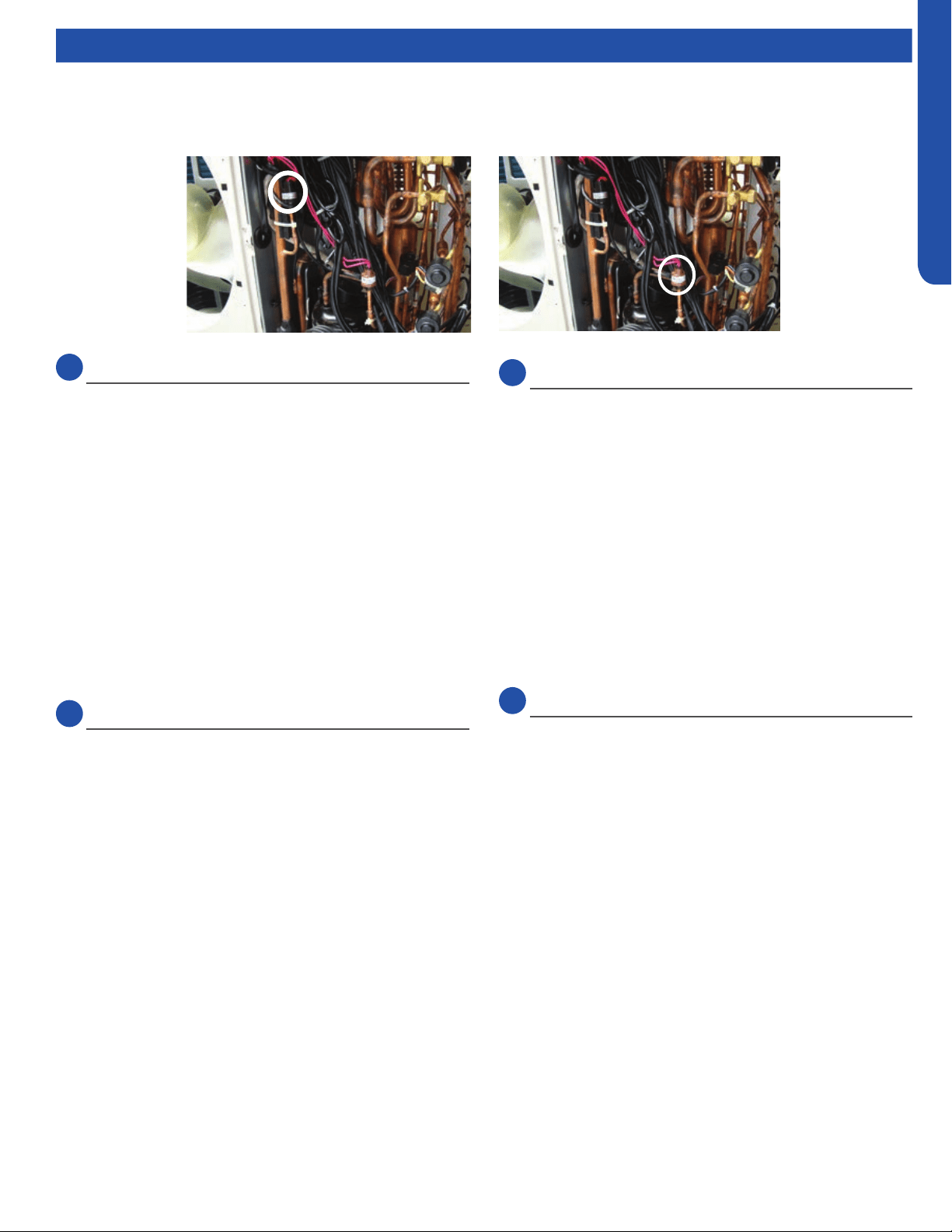
TROUBLESHOOTING & REFERENCES
J-17
ENGLISH
Outdoor Unit Error Codes
Error Code 42 & 43
The low pressure switch will generate an Error Code 43 if
open. An open high pressure switch will show an Error Code
42.
Testing Procedure
If the system generates either of these two codes, check the
continuity of the switch to ensure it is not open or shorted.
High or low pressures are usually related to dirt in the coils,
dirt in the air lter, or incorrect refrigerant charge.
There are no pressure ports that can be accessed to measure
low pressure in heat mode nor high pressure in cool mode. If
the system trips on one of these errors, it will be necessary to
remove the refrigerant and re-charge to conrm low or high
charge is not causing the problem.
Error Code 44
The system is operating at excessive refrigerant pressure. If
the system is a new installation, it is likely that the charge is
too high. Note the Weight Method is the ONLY way to charge
this system.
Typical Causes of High Pressure in Cooling Mode:
• Overcharge
• Dirty outdoor coil
• Restriction
Typical Causes of High Pressure in Heating Mode:
• Overcharge
• Undersized refrigerant lines or excessive length
• Restriction
Note: If the refrigerant pressures are correct, yet the system
does not close the error reporting pressure switch, replace the
defective pressure switch.
LowLow
PressurePressure
SwitchSwitch
High Pres-High Pres-
suresure
SwitchSwitch
Error Code 45
This code is indicating that system pressure is too low.
Typical Causes of Low Pressure in Cooling Mode:
• Lack of charge
• Low Heat on Indoor coil
• Restrictions, air ow, or dirt
• Low indoor load
Typical Causes of Low Pressure in Heating Mode:
• Cold outdoor air
• Lack of charge
• Restriction
Pressure-Related Error Codes
To protect the compressor, the PCB has a low pressure switch connection at CN13, and a high pressure switch connection at
CN12.
Communication Error Code
Error Code 15
Data travels between the units on the terminal block
connections 3/C and 1. A correct connection for each unit is
indicated by a solid green LED on the Service Monitor Board.
If an LED is ashing or not on, make sure the 14/4 stranded
copper communication cable connections are tight and
on the correct terminals. Additionally, ensure there are no
splices in the 3/C wire, and that the PCB connections at CN21
are in good order. An incomplete or inadequate ground can
easily be an issue.

TROUBLESHOOTING & REFERENCES
J-18
ENGLISH
Outdoor Unit Error Codes
Error Codes Caused by Abnormal Refrigerant Circuit
Conditions
Error Code 8
This code indicates the temperature of the compressor hot
gas is too high. This error occurs after the PCB has attempted
to correct high temperature by reducing the compressor
speed, adjusting the fan speed, or opening the EEV. Causes
of this type of condition are typically a lack of refrigerant in
the system, excessive heat in the conditioned space, or a
restriction in the refrigeration circuit.
Error Code 16
This error code indicates the system may lack refrigerant.
Recover and check the system charge.
Outdoor Error Code Related to Indoor Unit
Error Code 21
This code indicates the indoor coil has frosted. This condition
can be due to a lack of heat in the conditioned space,
operating the indoor unit at excessively cold air temperature,
a blockage of air ow to the indoor unit, or an issue with the
indoor fan motor. This condition will cause the system to
enter an anti-freezing cycle.
Error Code Related to the PCB
Error Code 1
The EEPROM of the PCB cannot read or write data. Replace
the PCB.
Error Codes Related to the IPM
Error Code 2
The IPM has either failed or has detected excessive current.
Before replacing the IPM, check these potential causes of
high current:
• Overcharge
• Dirty outdoor coil
• Hot conditioned space
• High temperature or excessive load
• Refrigeration circuit restriction
• Seized compressor
• Faulty wiring or wiring connections
Error Code 4
This code indicates the IPM is not communicating with the
PCB. Check the wiring and the connections CN9 on the
PCB and CN15 on the IPM. If the connections are good, yet
the boards do not communicate and the code will not clear,
check for correct voltage at the IPM CN15 connection. If the
communication voltage is correct and the high voltage input
is present, replace the IPM. If the communication voltage is
not correct, replace the PCB.
Error Code 5
The IPM is protecting the compressor from overload, which
can be caused by low building power supply, restrictions, a
non-condensible in the system, a plugged coil, an excessive
load, or a refrigerant overcharge.
Error Code 6
This code indicates the operating voltage of the system
is either too high or too low. Check line voltage for proper
limits. The line voltage supplied to the outdoor unit should
be no lower than 187VAC when the compressor starts.
The running voltage should be no lower than 197VAC. The
incoming line voltage to the outdoor unit should never be
higher than 253VAC. If improper voltage is present, check the
supply voltage circuit from the building for correct wire size
and good connections. If the voltage is still outside operating
limits, contact the power company to have the service
corrected.
If the line voltage from the power company is correct, check
the output voltage of the Power Filter. This voltage connects
to the IPM at terminals ACL and ACN.
If the voltage is not within specications shown above,
replace the PFB.
Error Code 18
There is a loss of synchronization among the U, V, and W
compressor windings during frequency changes as they slow
down or speed up the compressor.
Possible causes include:
• Unstable power supply
• Internal compressor fault
• IPM fault
• Compressor terminal wiring incorrect
• Poor wiring condition
• Loose compressor wiring connection

TROUBLESHOOTING & REFERENCES
J-19
ENGLISH
Outdoor Unit Error Codes
Error Code 23
This code indicates an IPM thermal overload. This error
was generated by a temperature sensor located in the IPM
heat sink. Causes of overheating are typically overcharge
of refrigerant, excessively plugged coil, sensor open or
shorted, or a non-condensable in system.
Error Code 26
Module reset indicates possible PCB power anomalies. This
usually occurs when low line voltage conditions are present.
Error Code 27
The IPM has detected that the compressor current is too
high.
Possible Causes:
• Overcharge
• Dirty outdoor coil
• Hot conditioned space temperature or high load
• Refrigeration circuit restriction
• Seized compressor
• Defective IPM
Error Codes Related to Compressor, Outdoor Fan &
4-Way Valve
Error Code 9
This code indicates the outdoor fan motor is not running. The
fault is detected very quickly by the PCB. The system will shut
o and display this error code. If this error occurs, refer to the
outdoor fan motor test procedure.
Error Code 17
This error code indicates that the 4-way valve is not directing
hot gas to the proper coil. Refer to the 4-way valve testing
procedure.
Error Code 24
This error code indicates the compressor failed to start when
a call for operation occurred. Refer to the compressor testing
procedure.
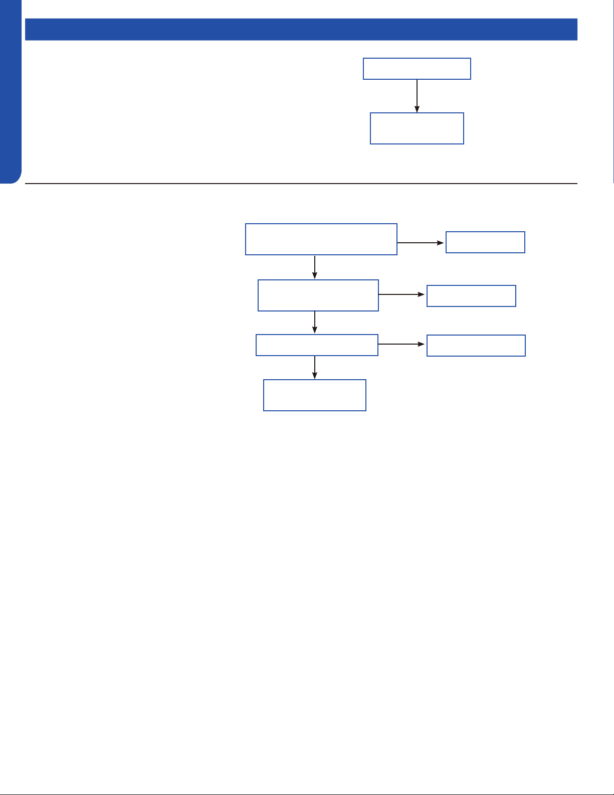
TROUBLESHOOTING & REFERENCES
J-20
ENGLISH
Topic TitleFlow Charts
Code disappears after
power off/on again
Check outdoor
PCB, If faulty,
replace it.
No
[1] Outdoor EEPROM Malfunction
EEPROM communication error; EEPROM data check
error (model ID, checksum, etc.); EEPROM data logic
error (wider data range, wrong order, etc.)
Possible causes:
• EEPROM is bad
• Loose EEPROM wiring
Correct the wiring
Is electric box wiring correct,
and is compressor wiring firmly
connected?
Is compressor normal
(compressor coil resistor,
insulation)?
Is power module normal?
Replace compressor
Replace power module
Ye s
Ye s
Ye s
No
No
No
Solve or correct any
failures according to
relative information
[2] Outdoor IPM over current or short circuit
3U24EH2VHA
Input over current detected by PIM’s hardware.
Possible causes:
• The IPM is bad
• Loose compressor wire
• The compressor is bad
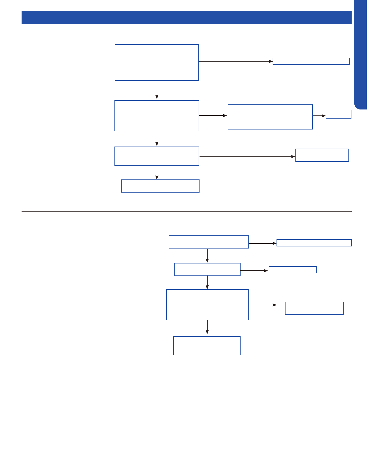
TROUBLESHOOTING & REFERENCES
J-21
ENGLISH
Topic TitleFlow Charts
Adjust communication wire
Is the compressor drive module
input power normal (Test the
AC power supply voltage of the
module’s power input ACL-ACN:
normal value should between 196-
253VAC)?
Check the AC voltage between
the two terminals of power filter
board board P7& the terminal 3
of relay RL1 (208-230VAC)
Ye s
Normal
No
Is the AC power supply wire
between compressor drive
module and filter
board firmly connected?
Fix wiring
Abnormal
Check if the output of main
control board CN6,CN34 are
both DC 12V
No
Main control board
is bad, replace.
No
The filter board is broken,
replace the filter board
No
[4] Communication abnormal between PCB and IPM
Control board can not
communicate with the
compressor driver module for
over 4 minutes
Possible causes:
• The communication wire is bad
• The PCB is bad
• The power module is bad
Correct power supply
Is power supply voltage
normal?
Is electric box wiring
correct?
Is power module voltage
between terminal P&N more
than 390V or less than 160V
during operation?
Correct the wiring
Replace power
module
Ye s
Ye s
No
No
Check rectifier, rector,
electrolytic capacitor on
inverter main circuit
No
Ye s
[6] DC voltage or AC voltage high
Driver module AC power supply voltage over 280VAC,
or driver module DC-BUS voltage over 390VDC.
Possible causes:
• The power supply is abnormal
• Incorrect wiring
• Power module is bad

TROUBLESHOOTING & REFERENCES
J-22
ENGLISH
Topic TitleFlow Charts
[8] Discharge temperature too high protection
Reconnect
Is sensor wiring firmly in place?
Is sensor resistance
within range?
Is the system is clogged?
Is the PMV coil wiring ok?
Is stop valve is open?
Replace pressure
switch
Check the piping system
Charge refrigerant
Check the piping system
Reconnect
Ye s
No
Ye s
Ye s
No
Ye s
No
No
Ye s
No
No
Is the ambient temperature too
high?
Replace connecting
board
Ye s
No
Is the system low on
refrigerant?
3U24EH2VHA
Compressor discharge temperature over 115°C. Error
clears within 3 minutes if temperature lowers below
115°C. Error status lock if it occurs 3 times in 1 hour.
Possible causes:
• The sensor is bad or xed bad
• The system is clogged
• The system lack of refrigerant
• The valve opening is wrong
Replace wire and test again
Are the fan motor wires
conductive?
Is the motor running?
Power off and rotate the
fan motor by hand. Does
it turn freely?
Is the terminial voltage
correct?
Replace
PCB
Replace fan
motor
Replace
PCB
Ye s
Ye s
Ye s
Ye s
No
No
No
No
Replace fan motor
[9] DC fan motor fault
DC fan motor damaged, not connected, or related
circuit broken. Error status conrms and locks if occurs
3 times within 30 minutes.
Possible causes:
• Loose motor wiring
• The motor is bad
• The PCB is bad
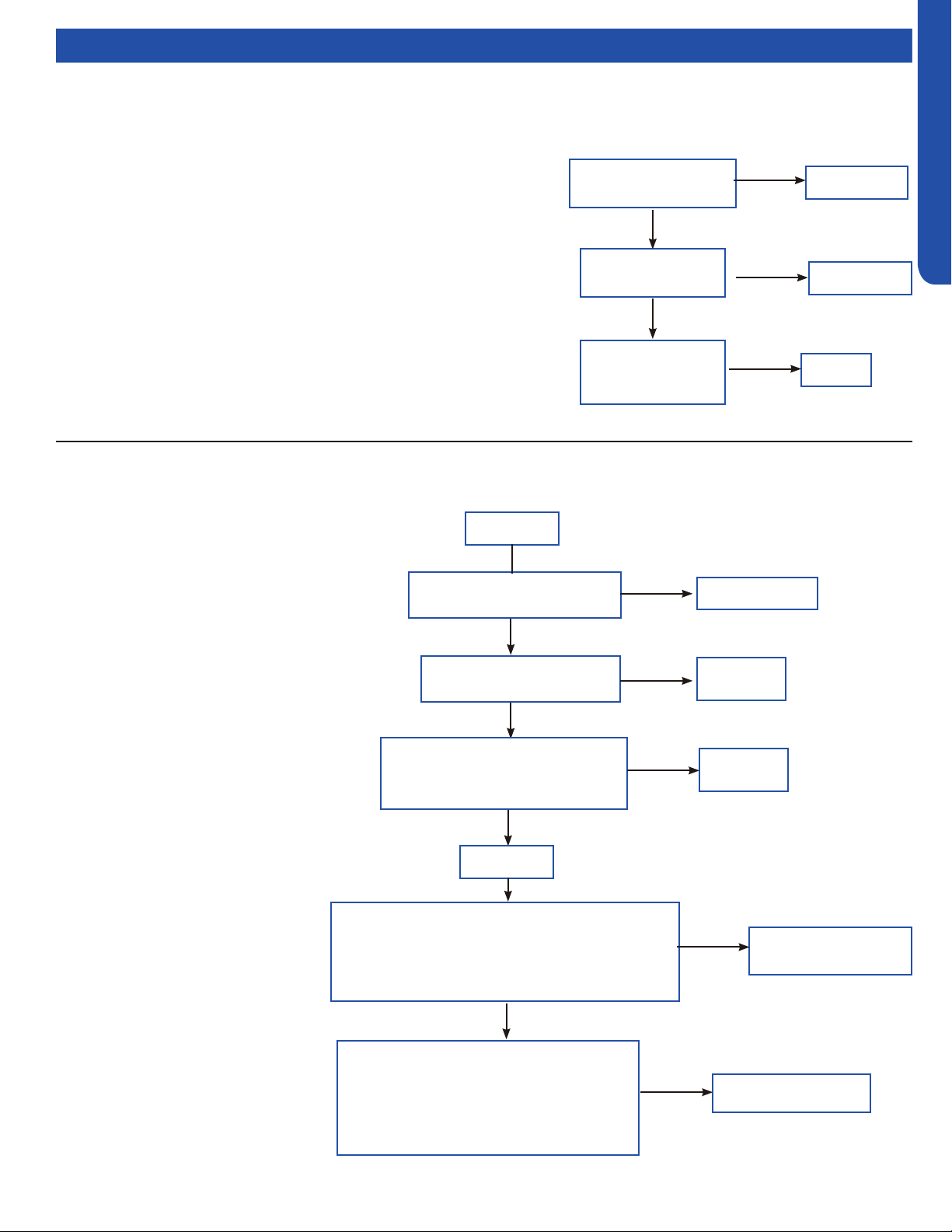
TROUBLESHOOTING & REFERENCES
J-23
ENGLISH
Topic TitleFlow Charts
Replace
sensor
Is the sensor wiring
firmly and correctly in
place?
Is the sensor
resistance within
range?
Is the temperature
loop acquired by
the computer board
normal?
Replace
sensor
Replace
it.
No
No
Ye s
Ye s
Ye s
[10] Outdoor defrosting temp. sensor Te abnormal
[11] Suction temp.sensor Ts abnormal
[12] Outdoor ambient temp. sensor Ta abnormal
[13] Discharging temp. sensor Td abnormal
Sensor temperature has been detected below or higher than expected,
or the sensor has been detected as a shorted or open circuit.
(for expected temperature, refer to part failure code)
Possible causes:
• Bad sensor connection
• The sensor is bad
• Sensor resistance drift
• The temperature acquired by PCB is not accurate
Replace wire
Is the communication wire is
shorted?
Is the communication wire
CN21 is disconnected?
Reconnect
Reconnect
Ye s
No
No
Ye s
Is the wiring connection sequence
correct according to the wiring
diagram?
No
Measure the outdoor terminal block voltage
between communication 3 and N, and measure the
indoor terminal block between communication 3
and N to check. Is the communication wire ok?
Ye s
Replace the
communication wire
Power off
Power on
No
Ye s
Using a multimeter, measure the terminal
corresponding to the N-line voltage of CN21
from the indoor unit with the communication
failure. Is the voltage normal?
No
PCB is bad, replace PCB
[15] Communication abnormal between indoor unit and outdoor unit
Outdoor unit control board cannot communicate
with the indoor unit control board for over 4
minutes.
Possible causes:
• Bad communication wiring
• The PCB is bad

TROUBLESHOOTING & REFERENCES
J-24
ENGLISH
Topic TitleFlow Charts
[16] Lack of refrigerant or discharging pipe blocked
Discharge & suction temperature Td-Ts≥80°C 10 minutes
after compressor start. Error status locks if it occurs 3 times
in 1 hour.
Possible causes:
• Wrong sensor connection
• Lack of refrigerant
• The senor is bad
• The 4-way valve is bad
• The electronic expansion valve is bad
• Out of the operating range
Correct wiring
Is the sensor wiring correct
and firmly connected?
Is the system leaking, or
lacking refrigerant?
Is the resistance of the
Td and the Tcm sensors
within range?
Repair leak and recharge
refrigerant
Replace the
sensor
Ye s
No
Ye s
No
Use the unit according to
the allowable operating
range of the unit.
Ye s
Is there an Internal
leakage in the 4-way
valve?
No
Replace 4-way
valve
Ye s
No
Adjust the valve opening
Ye s
Is the electronic
expansion valve over
throttled?
[17] 4-way valve reversing failure
Indoor pipe & indoor ambient temperature Tm-Tai≥5°C
10 minutes after compressor started. Error status locks
if it occurs 3 times in 1 hour.
Possible causes:
• The 4-way valve is bad
• The PCB is bad
• The 4-way valve coil connection is bad
• The system pressure dierence is too small.
Reconnect
Is connection between the
4-way valve and PCB is good?
Is the 4-way valve coil
wiring firmly in place and
characteristics correct?
Is the system meeting
4-way valve reversing
conditions (Pd-
Ps>0.6Mpa)?
Is there air noise after 4-way
valve reverses, and the temp.
of connection pipes on 4-way
valve normal?
Correct wiring or replace
Check if the
compressor is running
Replace
PCB
Replace 4-way
valve
Ye s
Ye s
Ye s
No
Ye s
No
No
Ye s
No
Is 208/230VAC Measured on
PVB CN5 PCB after 4-way
valve reversing conditons are
met?
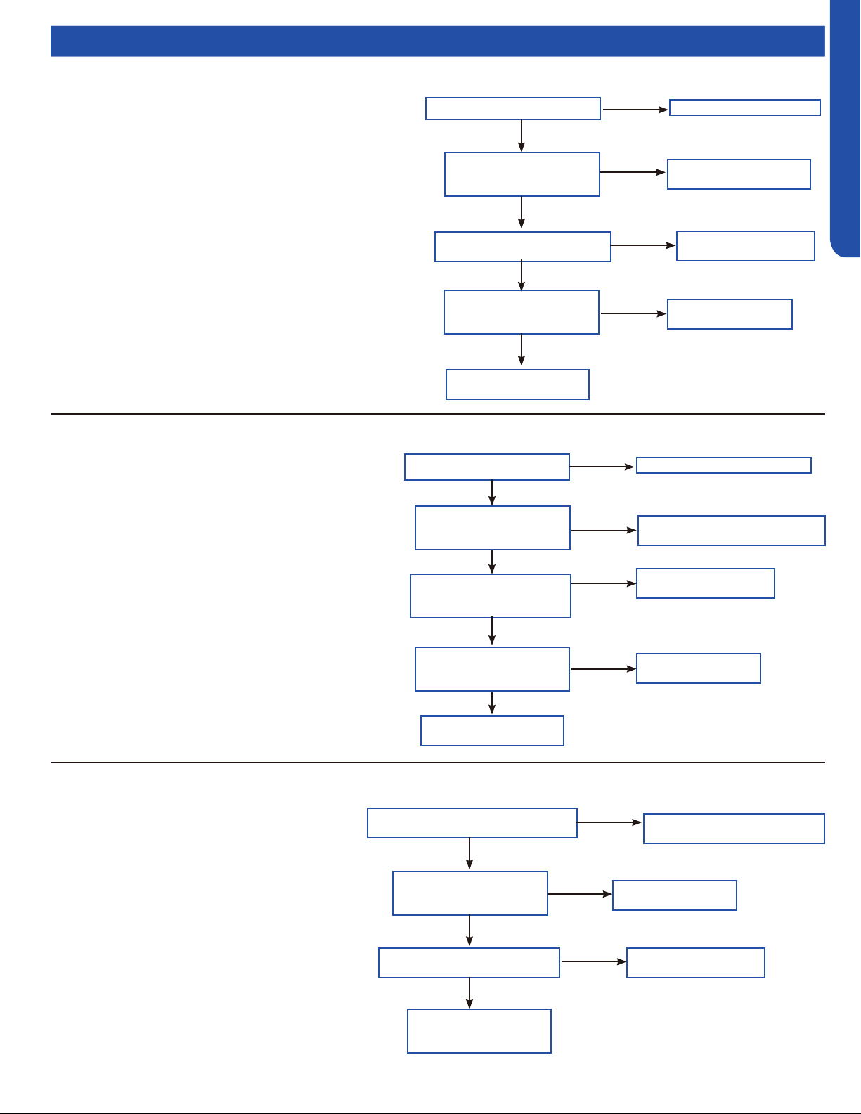
TROUBLESHOOTING & REFERENCES
J-25
ENGLISH
Topic TitleFlow Charts
Correct power supply
Is supply voltage normal?
Is wire connection
between power module
and compressor correct?
Is power module is normal?
Correct the wiring
according to diagram
Replace power
module
Ye s
Ye s
Ye s
No
No
No
Is compressor normal
(compressor coil resistor,
insulation)?
Replace
compressor
Ye s
No
Compressor load is too
high, find the reason
[18] Compressor motor desynchronizing
Motor desynchronizing occurred. Caused by overload, load
sharply uctuating, abnormal compressor current sensor
circuit, or one of the inverter gate drive signals is missing.
Possible causes:
• The power supply is abnormal
• Incorrect compressor wiring
• The power module is bad
• The compressor is bad
• The system is overload
Correct power supply
Is supply voltage normal?
Is wiring between power
module and compressor
correct?
Is power module is
normal?
Correct the wiring according
to diagram
Replace power
module
Ye s
Ye s
No
No
Compressor load too
high, find the reason
Ye s
Is compressor is normal
(compressor coil resistor,
insulation)?
No
Replace
compressor
No
[24] Compressor startup failure
Compressor start failure has been detected by driver
module.
Possible causes:
• The power supply is abnormal
• Incorrect compressor wiring
• The power module is bad
• The compressor is bad
• System overload
Correct the wiring according
to diagram
Is electric box and compressor
wiring correct and firmly in place?
Is compressor normal
(compressor coil resistor,
insulation)?
Is power module is normal?
Replace
compressor
Replace power
module
Ye s
Ye s
Ye s
No
No
No
[25] Input overcurrent of the drive module
Compressor drive module input current higher
than 32A (double fan model), or 27A (single fan).
Locks if it occurs 3 times in 1 hour.
Possible causes:
• Incorrect compressor wiring
• The power module is bad
• The compressor is bad
Solve or correct any
failures according to
relative information
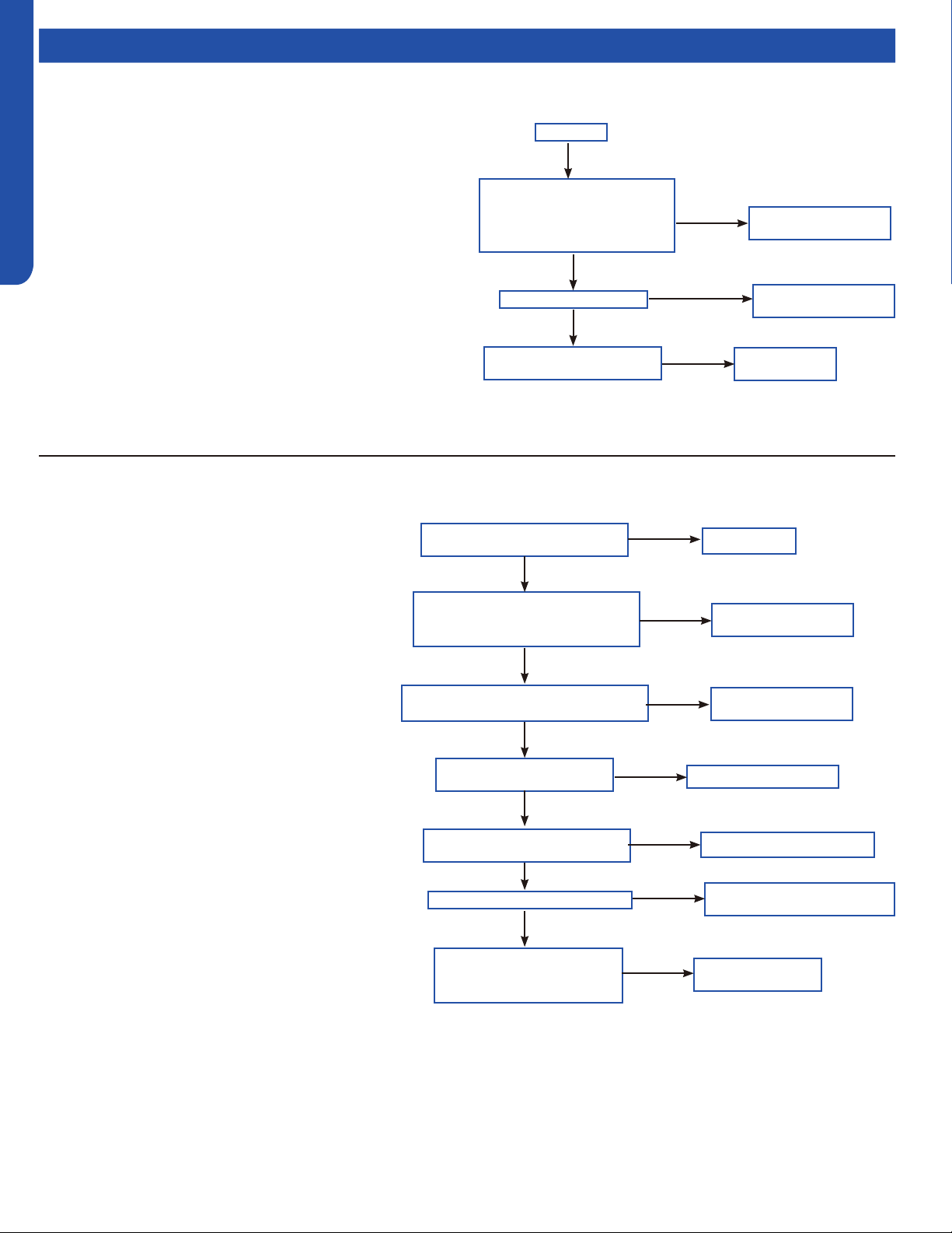
TROUBLESHOOTING & REFERENCES
J-26
ENGLISH
Topic TitleFlow Charts
Power on
Short the high pressure
switch terminal on the PCB.
Does the system report a
failure?
Is the fan motor is ok?
Is the resistance of Te and
Tc within range?
The PCB is bad,
replace it.
Replace
sensor
No
Ye s
Ye s
No
No
Replace the fan
motor
[42] Open high pressure switch
High pressure switch: Switch circuit has been detected open for
30 seconds (after 3 minute of compressor run time). Error locks
if it occurs 3 times in 1 hour.
Possible causes:
• Incorrect pressure switch wiring
• Abnormal system pressure
• System is clogged
• Incorrect refrigerant charge
• Bad valve
• Pressure switch is bad
• PCB is bad
Reconnect
Power off. Is pressure switch
wiring connection ok?
Use multimeter to check the high
pressure switch. Is the switch
short circuited?
Is the EEV coil wiring correct and
firmly in place?
Is the stop valve is open?
Use a multimeter to check
the resistance of Tc & Tm.
Are they withing range?
Is the piping system clogged?
Is the connection pipe bent?
The pressure is bad,
replace it.
Open the stop valve
Clean the piping system
Replace the connection
pipe
Replace the
sensor
Ye s
Ye s
No
Ye s
Ye s
No
No
No
No
No
Ye s
No
No
Reconnect the EEV
coil wiring
[43] Open low pressure switch
Low pressure switch: Switch has been detected open
for 60 seconds (after 3 minute of compressor run
time) or open for 30 seconds during standby.
Possible causes:
• Incorrect pressure switch wiring
• Abnormal system pressure
• System is clogged
• Incorrect refrigerant charge
• Bad valve
• Pressure switch is bad
• PCB is bad

TROUBLESHOOTING & REFERENCES
J-27
ENGLISH
Topic TitleFlow Charts
Reconnect
Power off. Is pressure switch
wiring connection ok?
Use multimeter to check the high
pressure switch. Is the switch
short circuited?
Is the EEV coil wiring correct and
firmly in place?
Is the stop valve is open?
Use a multimeter to check
the resistance of Tc & Tm.
Are they withing range?
Is the piping system is
clogged?
Is the connection pipe is bent?
The pressure is bad,
replace it.
Open the stop valve
Clean the piping system
Replace the connection
pipe
Replace the
sensor
Ye s
Ye s
No
Ye s
Ye s
No
No
No
No
No
Ye s
No
No
Reconnect the EEV
coil wiring
[44] High pressure detected in system
The minimum temperature value of indoor pipe Tm
and outdoor Ts is lower than -45 °C during cooling
mode, or minimum temperature value of outdoor Tc
and outdoor Te is lower than -45 °C.
Possible causes:
• High pressure sensor detection value is incorrect
• Refrigerant overcharge
• Blocked liquid line piping
• The outdoor unit cannot be turned on normally
due to failure to open outdoor heat exchanger
electronic expansion valve when heating.
• The operation environment is beyond the allowed
range.
Power on
Short the low pressure
switch terminal on the PCB.
Does the system report a
failure?
Is the fan motor ok?
Is the resistance of Te and
Tc2 in range?
The PCB is bad,
replace it.
Replace
sensor
No
Ye s
Ye s
Ye s
No
No
Replace the fan
motor
[45] Low pressure detected in system
The minimum temperature value of indoor pipe Tm and
outdoor Ts is lower than -45 °C during cooling mode, or
minimum temperature value of outdoor Tc and outdoor Te is
lower than -45 °C.
Possible causes:
• Low pressure sensor detection value is incorrect
• Low refrigerant charge
• System air leakage
• Blocked low pressure or liquid line piping
• The outdoor unit cannot be turned on normally due to failure
to open outdoor heat exchanger electronic expansion valve
when heating.
• The operation environment is beyond the allowed range.

www.haierductless.com
GE Appliances, A Haier Company
Appliance Park, Louisville, KY 40225
©2020 GE Appliances, A Haier Company
Issued Date: 8/27/2020