Owner's Manual
£RIIFTSMIIN+
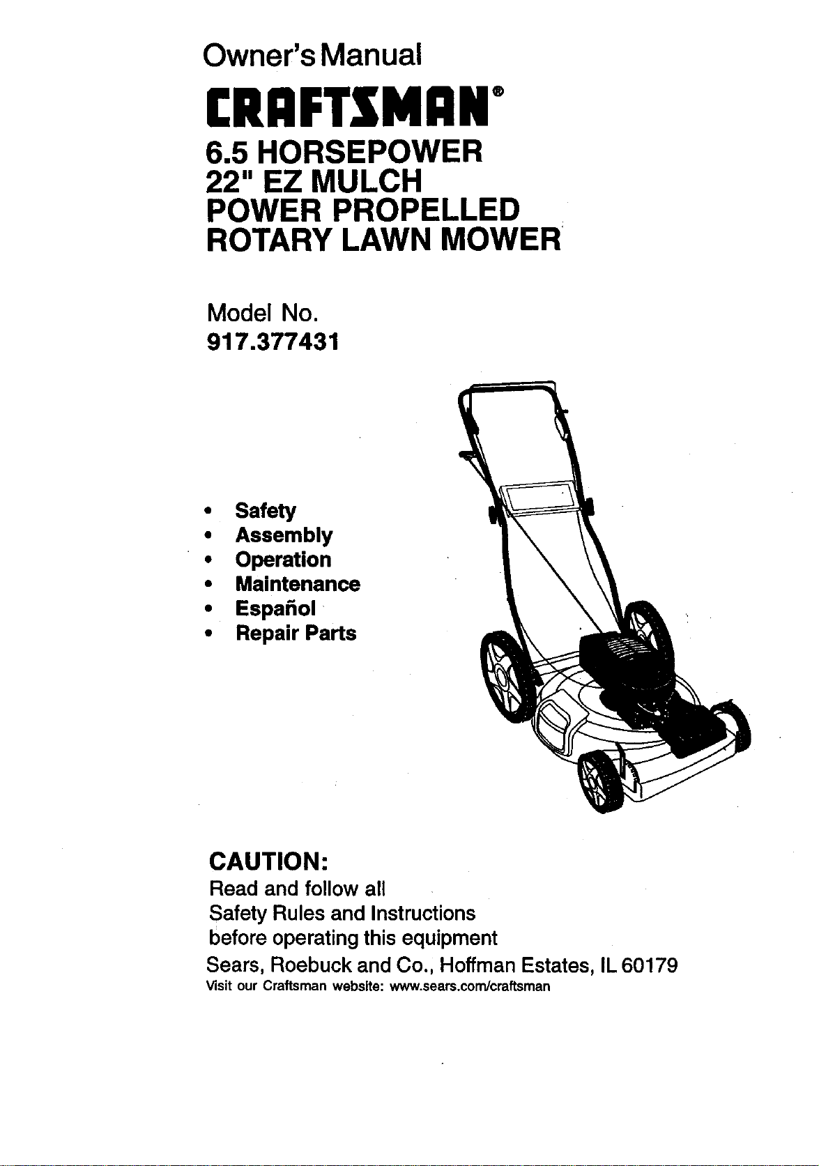
6.5 HORSEPOWER
22" EZ MULCH
POWER PROPELLED
ROTARY LAWN MOWER
Model No.
917.377431
• Safety
• Assembly
• Operation
• Maintenance
• Espa_ol
• Repair Parts
CAUTION:
Read and follow all
Safety Rules and Instructions
before operating this equipment
Sears, Roebuck and Co., Hoffman Estates, IL 60179
Visit our Craftsman webslte: www.sears.com/craftsman
Warranty 2 Product Specifications 11
Safety Rules 2 Service and Adjustments 14
Assembly 4 Storage 15
Operation 6 Troubleshooting 17
Maintenance"S'chedule 10 Repair Parts 36
Maintenance- " 10 Parts Ordering Back Cover
LIMITED TWO YEAR WARRANTY ON CRAFTSMAN
For two years from date of purchase, when this Craftsman Lawn Mower is maintained,
lubricated, and tuned up according to the operating and maintenance instructionsin
the owner's manual, Sears will repair free of charge any defect in material or workman-
ship.
If this Craftsman Lawn Mower is used for commercial or rental purposes, this warranty
applies for only 90 days from the date of purchase.
This Warranty does not cover:
• Expendable items which become wom during normal use, such as rotary mower
blades, blade adapters, belts, air cleaners and spark plug.
• Repairs necessary because of operator abuse or negligence, including bent
crankshafts and the failure to maintain the equipment according to the instructions
contained in the owner's manual.
Warranty service is available by retuming the Craftsman power mower to the nearest
Sears Service Center/Department inthe United States. This warranty applies only
while this product is in use in the United States.
This Warranty gives you specific legal rights, and you may also have other rights which
vary from state to state.
SEARS, ROEBUCKAND CO., D/817 WA, HOFFMAN ESTATES, ILLINOIS 60179
Safety standards require operator
presence controls to minimize the risk of
injury.Your unit is equipped with such
controls. Do not attempt to defeat the
function of the operator presence controls
under any circumstances.
TRAINING:
• Read this operator's manual carefully.
Become familiar with the controls and
know how to operate your mower
properly. Leam how to quicklystop
mower.
• Do not allow childrento use your mower.
Never allow adults to use mower without
proper instructions.
• Keep the area of operation clear of all
persons, especially small children and
pets.
• Use mower only as the manufacturer
intended and as described in this
manual.
• Do not operate mower if it has been
dropped or damaged in any manner.
Always have damage repaired before
using your mower.
• Do not use accessory attachments that
are not recommended by the manufac-
turer. Use of such attachments may be
hazardous.
• The blade tums when the engine is
running.
PREPARATION:
• Always thoroughlycheck the area to be
mowed and clear itof all stones,sticks,
wires, bones, and other foreign objects.
These objects willbe thrown by the
blade and can cause severe injury.
• Always wear safety glasses or eye
shields when starting and while using
your mower.
2
• Dress properly. Do not operate mower
when barefoot or weadng open sandals.
Wear only solid shoes with good traction
when mowing.
• Chock fuel tank before starting engine.
Do not fill gas tank indoors, when the
engine is running or when the engine is
hot. Allow the engine to cool for several
minutes before filling the gas tank. Clean
off any spilled gasoline before starting
the engine.
• Always make wheel height adjustments
before starting your mower. Never
attempt to do this while the engine is
running.
• Mow only in daylight or good artificial
light.
OPERATION:
• Keep your eyes and mind on your
mower and the area being cut. Do not let
other interests distractyou.
• Do not mow wet or slipperygrass. Never
run while operating your mower. Always
be sure ofyour footing-- keep a firm
hold on the handles and walk.
• Do not put hands orfeet near or under
rotatingpads. Keep clear of the dis-
charge opening at all times.
• Always stop the engine whenever you
leave or are not using your mower, or
before crossing driveways, walks, roads,
and any gravel---covered areas.
• Never direct discharge of material
toward bystanders nor allow anyone
near the mower while you are operating
it.
• Before cleaning, inspecting, or repairing
your mower, stop the engine and make
absolutely sure the blade and all moving
parts have stopped. Then disconnectthe
spark plug wire and keep it away from
the spark plugto prevent accidental
starting.
• Do not continue to run your mower ifyou
hit a foreign object. Follow the procedure
outlined above, then repair any damage
before restartingand operating you
mower.
• Do not change the governor settingsor
overspeed the engine. Engine damage
or personal injurymay result.
• Do not operate your mower if it vibrates
abnormally. Excessive vibration is an
indicationof damage; stop the engine,
safely chock for the cause ofvibration
and repair as required.
3
• Do not run the engine indoors. Exhaust
fumes are dangerous.
• Never cut grass by pulling the mower
towards you. Mow across the face of
slopes, never up and down or you
might lose your footing. Do not mow
excessively steep slopes. Use caution
when operating the mower on uneven
terrain or when changing directions --
maintain good footing.
• Never operate your mower without
proper guards, plates, grass catcher or
other safety devices in place.
MAINTENANCE AND STORAGE:
• Chock the blade and the engine
mounting bolts often to he sure they are
tightened properly.
• Chock all bolts, nuts and screws at
frequent intervals for proper tightness to
be sure mower is in safe working
condition.
• Keep all safety devices in place and
working.
• To reduce fire hazard, keep the engine
free of grass, leaves or excessive
grease and oil.
• Chock grass catcher often for deteriora-
tion and wear and replace worn bags.
Use only replacement bags that are
recommended by and comply with
specifications of the manufacturer of
your mower.
• Always keep a sharp blade on your
mower.
• Allow engine to cool before storing in
any enclosure.
• Never store mower with iuel in the tank
inside a building where fumes may
reach an open flame or an ignition
source such as a hot water heater,
p_gpaCe heater, clothes dryer, etc.
CAUTION: Always disconnect spark
wire and place wire wh_re it cannot
contact spark plug in order to prevent
accidental starting when setting up,
transporting, adjusting or making repairs.
_eWARNING
engine exhaust from this product
contains chemicals known to the State of
California to cause cancer, birth defects,
or other reproductive harm.
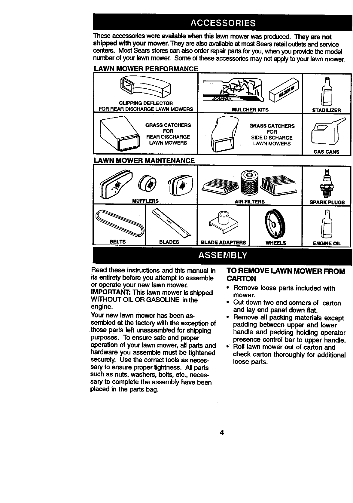
These acceasoneswere availablewhenthis lawnmowerwas produced.They are not
shipped with your mower. They are alsoavailableat mostSears retailoutletsand service
centers. MostSears storescan alsoorderrepairpartsforyou,whenyou providethe model
numberof yourlawnmower. Some ofthese accessoriesmay notapplytoyourlawn mower.
LAWN MOWER PERFORMANCE
MULCHER KITS
! GRASS CATCHERS
FOR
_( SIDE DISCHARGE
• LAWN MOWERS
CLIPPING DEFLECTOR
FOR REAR DISCHARGE LAWN MOWERS
GRASS CATCHERS
FOR
REAR DISCHARGE
LAWN MOWERS
LAWN MOWER MAINTENANCE
IE!
STABILIZER
GAS CANS
MUFFLERS
BLADES
AIR RLTERS
SPARK PLUGS
ENGINE OiL
Read these instructionsand this manual in
its entirety before you attempt to assemble
or operate your new lawn mower.
IMPORTANT: This lawn mower is shipped
WITHOUT OIL OR GASOLINE in the
engine.
Your new lawn mower has been as-
sembled at the factory withthe exception of
those parts left unassembled for shipping
purposes. To ensure safe and proper
operation of your lawn mower, allparts and
hardware you assemble must be tightened
securely. Use the correcttools as neces-
sary to ensure proper tightness. All parts
such as nuts, washers, bolts,etc., neces-
sary to complete the assembly have been
placed in the parts bag.
TOREMOVE LAWNMOWER FROM
CARTON
• Remove loose parts included with
mower.
• Cut down two end comers of carton
and lay end panel down flat.
• Remove all packing matedais except
padding between upper ahd lower
handle and padding holding operator
presence control bar to upper handle.
• Roll lawn mower out of carton and
check carton thoroughly for additional
loose pads.
4
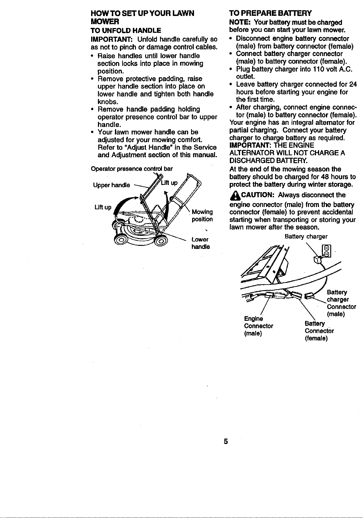
HOW TO SET UP YOUR LAWN
MOWER
TO UNFOLD HANDLE
IMPORTANT: Unfold handle carefully so
as not to pinch or damage control cables.
• Raise handles until lower handle
section locks into place in mowing
position.
• Remove protective padding, raise
upper handle section into place on
lower handle and tighten both handle
knobs.
• Remove handle padding holding
operator presence control bar to upper
handle.
• Your lawn mower handle can be
adjusted for your mowing comfort.
Refer to "Adjust Handle" in the Service
and Adjustment section of this manual.
Operator presence control bar
Upper handle
Lift up
Mowing
position
Lower
handle
TO PREPARE BATTERY
NOTE: Your battery must be charged
before you can start your lawn mower.
• Disconnect engine battery connector
(male) from battery connector (female)
• Connect battery charger connector
(male) to battery connector (female).
• Plug battery charger into 110 volt A.C.
outlet.
• Leave battery charger connected for 24
hours before starting your engine for
the first time.
• After charging, connect engine connec-
tor (male) to battery connector (female).
Your engine has an integral altemator for
partial charging. Connect your battery
charger to charge battery as required.
IMPORTANT: THE ENGINE
ALTERNATOR WILL NOT CHARGE A
DISCHARGED BATTERY.
At the end of the mowing season the
battery should be charged for 48 hours to
protect the battery during winter storage.
&CAUTION: Always disconnect the
engine connector (male) from the battery
connector (female) to prevent accidental
starting when transporting or storing your
lawn mower after the season.
Battery charger
Battery
Connector
(male)
Engine
Connector Battery
(male) Connector
(female)
5
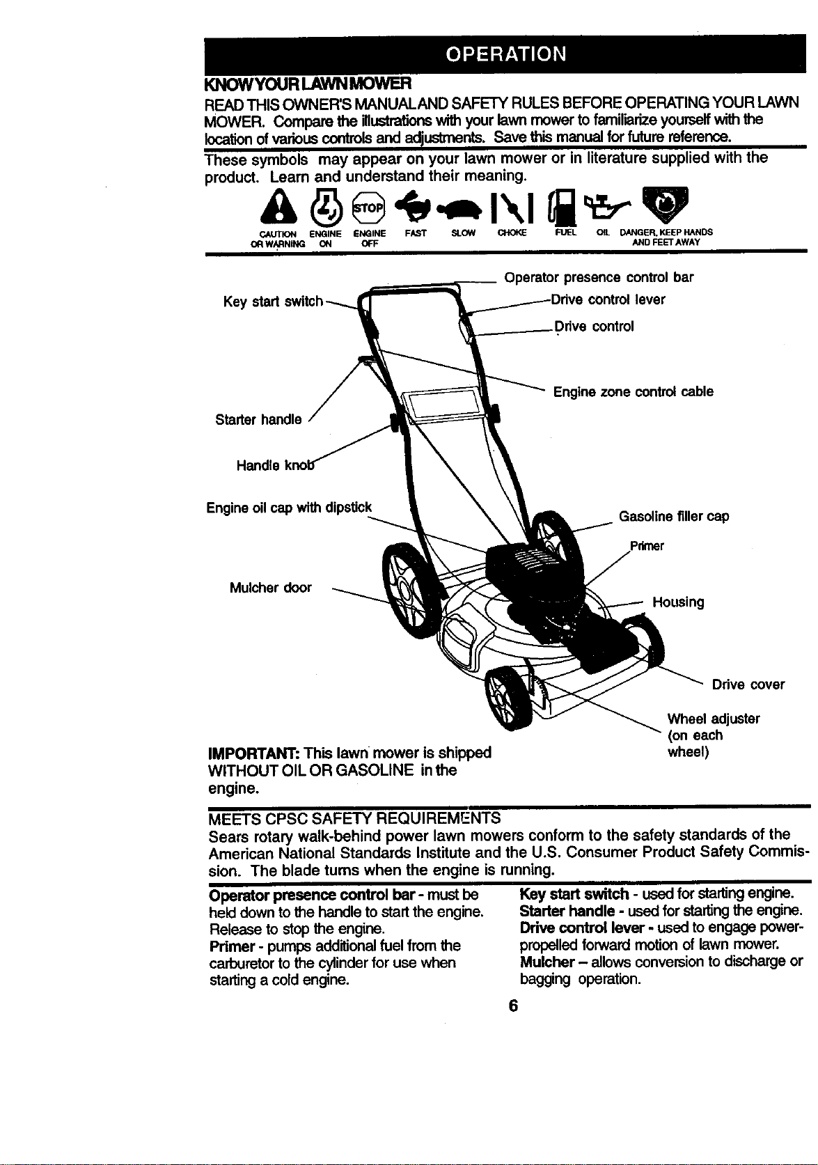
KNOW YOUR LAWN MOWER
READTHIS OWNER'S MANUAL.ANDSAFETY RULES BEFORE OPERATING YOUR LAWN
MOWER. Compare the illustrationswithyourlawnmowertofamiliarizeyourselfwiththe
locationofvariouscontrolsand adiustments. Save thismanual forfuturereference.
These symbols may appear on your lawn mower or in literature supplied with the
product. Learn and understand their meaning.
CAUTION ENGINE ENGINE FAST SLOW CHOKE FUEL OIL D._NGER,KEEPHANDS
OFtW/_RNING ON OFF AND FEETAWAY
Key start
__ Operator presence control bar
lever
Starter handle
Engine zone control cable
Handle
Engine oil cap with dipstick
Gasoline filler cap
Primer
Mulcher door
Housing
Drive cover
IMPORTANT: This lawn mower is shipped
WITHOUT OIL OR GASOLINE inthe
engine.
Wheel adjuster
(on each
wheel)
MEETS CPSC SAFETY REQUIREMENTS
Sears rotary walk-behind power lawn mowers conform to the safety standards of the
American National Standards Institute and the U.S. Consumer Product Safety Commis-
sion. The blade turns when the engine is running.
Operator presence contr_ bar- must be
held down to the handle to start the engine.
Release to stop the engine.
Primer - pumps additional fuel from the
carburetor to the cylinder for use when
starting a cold engine.
Key start switch - used for starting engine.
Starter handle - used for starting the engine.
Drive control lever - used to engage power-
propelled forward motion of lawn mower.
Mulcher - allows conversion to discharge or
bagging operation.
6
The operationofany lawnmower can resultin
foralgnobjectsthrownintotheeyee,whichcan
resultinsevere eye damage, Alwayswear
safetyglassesoreye shieldswhileoperaling
yourlawnmowerorperforminganyadjust-
mentsorrepairs. We recommenda wide
visionsafetymaskover spectaclesorstandard
safetyglasses.
HOWTOUSE YOUR LAWNMOWER
ENGINE SPEED CONTROL
The engine speed was set at the factory
for optimum performance. Speed is not
adjustable.
ENGINE ZONE CONTROL
,_CAUTION : Federal
regulations
require an engine control to be installed
on this lawn mower in order to minimize
the risk of blade contact injury. Do not
under any circumstances attempt to
defeat the function of the operator control.
The blade turns when the engine is
running.
• Your lawn mower is equipped with an
operator presence control bar which
requires the operator to be posi_oned
behind the lawn mower handle to start and
operate the lawn mower.
DRIVE CONTROL
• Self-propelling is controlledby holding the
operator presence control bar down to the
handle and pushing the drive control lever
forward until it clicks; then release the lever.
• Forward motion will stop when the operator
presence control bar is released. To stop
forward motion without stopping engine,
release the operator presence control bar
slightly until the drive control disengages.
Hold operator presence control bar down
to handle to continue mowing without self-
propelling.
• To keep drive control engaged when
turning corners, push down on handle and
liftfront wheels off ground wh=letuming
lawn mower.
Operator presence control Drive
bar "" "_\ " t control
\_ \_ Drive control
To engage drive control disengaged
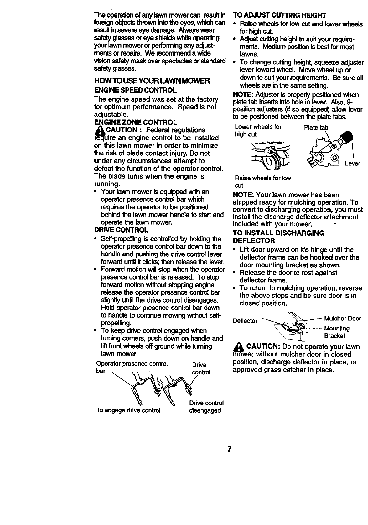
TO ADJUST CUTrlNG HEIGHT
• Raise wheelsfor lew cut and lowerwheels
forhighcoL
• Adjustcuttingheightto suityour require-
merits. Medium positionis bestformost
lawns.
• To change cuttingheight,squeeze adjuster
levertowardwheel. Move wheel up or
down to suityourrequirements. Be sure all
wheels are inthe same setting.
NOTE: Adjusteris properlypositionedwhen
platetab insertsintoholein lever. ALso,9-
positionadjusters(ifso equipped)allow lever
to be positionedbetween the platetabs.
Lower wheels for
high cut
Plate tab
Raise wheels for low
cut
NOTE: Your lawn mower has been
shipped ready for mulching operation. To
convert to discharging operation, you must
install the discharge deflector attachment
included with your mower.
TO INSTALL DISCHARGING
DEFLECTOR
• Liftdoor upward on it'shinge until the
deflector frame can be hooked over the
door mounting bracket as shown.
• Release the door to rest against
deflector frame.
• To retum to mulchingoperation, reverse
the above steps and be sure door is in
closed position.
_ _, ,_'_._ Mulcher Door
Deflector
_ _------ Mounting
Bracket
_lb CAUTION: Do not operate your lawn
mower without mulcher door in closed
position, discharge deflector in place, or
approved grass catcher in place.
7
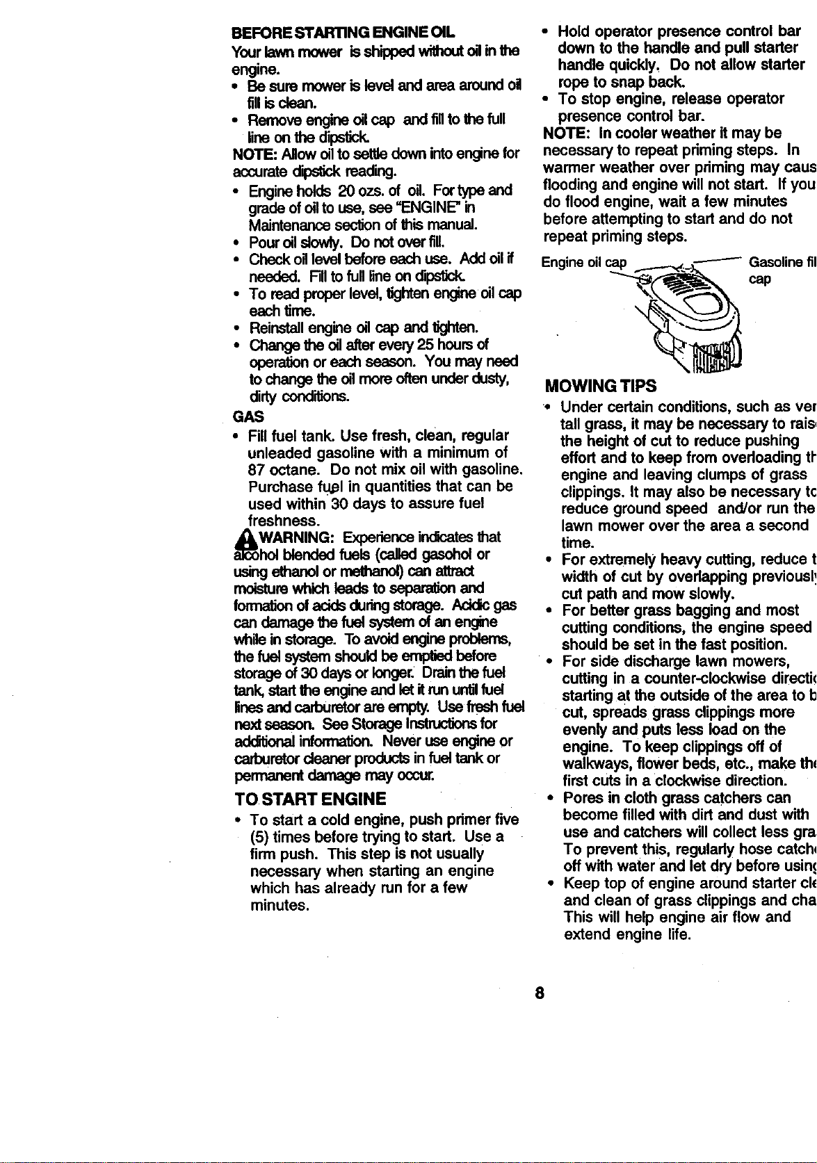
BEFORE STAR'RNG ENGINE OIL
Yourlawnmower isshippedwithoutoginthe
engine.
• Be sum moweris leveland area aroundoil
fillisclean.
• Remove engine oilcap and tifftothefull
fineonthe dipstick.
NOTE: Allowoilto settledownintoenginefor
accuratedipstk_ reeding.
• Engineholds 20 ozs. of oil. Fortypeand
grade ofoilto use,see =ENGINE"in
Maintenancesectionof thismanual.
• Pouroil slowly. Do notover fill
• CheckoHlevelboforeeach use. Addoilif
needed. Fillto full 5neondipstick.
• To read properlevel,tightenengineoilcap
each time.
• Reinstallengine o_1cap and tighton.
• Change the oil afterevery25 hoursof
operationor each seeson. You may need
tochange the oilmere oftenunderdusty,
dirty conditions.
GAS
• Fill fuel tank. Use fresh, clean, regular
unleaded gasoline with a minimum of
87 octane. Do not mix oil with gasoline.
Purchase fu_l in quantities that can be
used within 30 days to assure fuel
freshness.
_oARNING: Experienceindicatesthat
blended fuels (calledgasoholor
usingathanol or methanel)can attrect
moisturewhichleads to separationand
formationof acidsdudngstorage. Addicges
candamage the fuel systemof an engine
whileinstorage. To avoidengineproblems,
the fuel systemshould be emptiedbefore
storageof 30 daysor longer. Drainthefuel
tank,startthe engineend letitrununtilfuel
lfnseand carburatorare empty. Usefroshfuel
nextseeson. See Storage Instructionsfor
additionalinfom_tion. Never useengine or
carburetordeaner productsin fueltank or
penxenent damage may occur.
TO START ENGINE
• To start a cold engine, push primer five
(5) times before trying to start. Use a
firm push. This step is not usually
necessary when starting an engine
which has already run for a few
minutes.
• Hold operator presence control bar
down to the handle and pull starter
handle quickly, Do not allow starter
rope to snap back.
• To stop engine, release operator
presence control bar.
NOTE: In cooler weather itmay be
necessary to repeat priming steps. In
warmer weather over priming may caus_
flooding and engine will not start. If you
do flood engine, wait a few minutes
before attempting to start and do not
repeat priming steps.
Engine oilcap
cap
\
MOWING TIPS
•• Under certain conditions, such as ver_
tall grass, it may be necessary to raise
the height of cut to reduce pushing
effort and to keep from overloading thq
engine and leaving clumps of grass
clippings. It may also be necessary to
reduce ground speed and/or run the
lawn mower over the area a second
time.
• For extremely heavy cutting, reduce tt
width of cut by overlapping previously
cut path and mow slowly.
• For better grass bagging and most
cutting conditions, the engine speed
should be set in the fast position.
• For side discharge lawn mowers,
cutting in a counter-clockwise directio
starting at the outside of the area to b_
cut, spreads grass clippingsmore
evenly and puts less load on the
engine. To keep clippings off of
walkways, flower beds, etc., make the
first cuts in a clockwise direction.
• Pores in cloth grass catchers can
become filled with dirt and dust with
use and catchers will collect less gras
To prevent this, regularly hose catche
off with water and let dry before using
• Keep top of engine around starter cle
and clean of grass clippings and chaf
This will help engine air flow and
extend engine life.
8
MULCHING MOWING TIPS
IMPORTANT: For beatparformance, keep
mowerhousingfree ofbuilt-upgrass and
trash.See "Cleaning"in MAINTENANCE
sectionofthismanual.
• The specialmulchingbladewillrecutthe
grassclippingsmany timasand reduce
them insizeso thatasthey fallontothe
lawn they willd'_oerseintothegrassand
notbe noticed. Also,the mulchedgrasswill
biodegradequicldyto providenutrientsfor
the lawn. Alwaysmulchwithyourhighest
engine(blade)speed as this willprovidethe
bestrecuttingac_onofthe blades.
• Avoidcuttingyourlawnwhenit iswet. Wet
grasstendstoform dumps andinterferes
withthe mulchingaction. The besttimeto
mow yourlawnisthe earlyafternoon,At
this timethe grasshas driedand the newly
cutarea willnot be exposedtothe dirsct
sun.
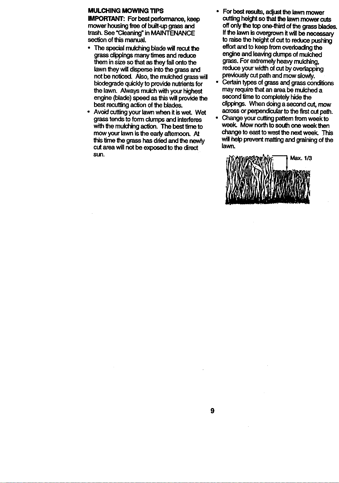
• For bastrasults,adjustthelawn mower
cuttingheightso that thelawnmowercuts
offonlythe topone-thirdof the grassblades,
ffthe lawn isovergrownitw111be necessaly
to raisethe heightofcutto reducepushing
effortandto keepfromoverloadingthe
engineand leavingdumpsof mulched
grass.Forextremelyheavymulching,
reduceyourwidthofcutbyoverlapping
previouslycutpathand mowslowly.
• Certaintypesofgrassand grassconditions
may requirethatan area be mulcheda
secondtimetocompletelyhidethe
clippings.Whendoinga secondcut,mow
acrossorperpendiculartothe firstcutpath.
• Changeyourcuttingpattemfromweekto
week. Mow northtosouthone week then
_ to easttowastthe nextweek. This
willhelppreventmattingand grainingofthe
lawn.
9
M..NTEN..CESC. OUL
'"
AS YOU COMPLETE /_/_/_-_X'_.v,'_'" *........
iiiii lIB
CheckforLooseFastenem I/ li/
Clean/InspectGrassCatcher
Clean Under Dd_ Cover
W (Power-ProP (WledMowers )Check drive belt_ulleys .j
(Power.Propelled Mowers)
R : CheckJShaq_dReplace Blade =
i Lubdcalton Chart I/
CleanBatteryiRecharip
IElect_ StartMowerst 1/ I/4
i Check Engine Oil Level le#
Change Engine Oil 1/1.2
Clean Air Rlter 1/2
InspectMuffler
r,
Replaea Air Filter Paper Cartridge 1/2
t - ChangemoreoftenwlHmoperatingunderAheaw loadorInIdghambleNtempemture_
2- servicemoreoft_ _twmopemingIndirlyordusly€onditions.
3- ReplaceIdad_ moreo1_ whenmov,tngk_m-,dy_L
4- Charge48 houmat_d of_alon.
GENERAL RECOMMENDATIONS
The warrantyonthislawnmowerdoesnot
coveritemsthathave beensubjectedto
operatorabuse or negrNgonce.Toreceivefull
valuefromthewarranty,operatormust
maintainmoweras instructedinthismanual.
Some adjustmentswillneedto be mede
pedodK_dlyto properly maintainyourunit.
Alladjuslmentsinthe ServloeandAdjust-
mentssectionofthis manualshouldbe
checkedatleastonceeach season.
• Onceayear, replacethe sparkplug,clean
or replaceairfilterelementand checkblade
forwear. A newsparkplugand clean/new
air filterelementassuresproperair-fuel
mixtureand helpsyourenginerunbetter
and lastlonger.
• Followthe maintenancescheduleinthis
manual.
BEFORE EACH USE
• Check engine oillevel.
• Check for loose fasteners.
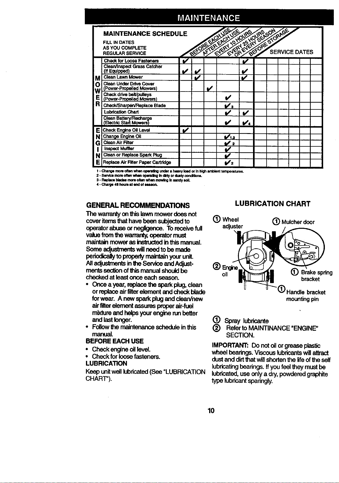
LUBRICATION
Keep unit well lubricated (See "LUBRICATION
CHART").
LUBRICATION CHART
O Wheel (_) Mulcher door
adjuster
oil
(_) Brake spring
bracket
(D Handle bracket
mounting pin
(_) Spray lubricante
(_) Referto MAINTINANCE "ENGINE"
SECTION.
IMPORTANT: Do not oil or grease plastic
wheel bearings. Viscous lubricants will attract
dust and dirtthat will shorten the life ofthe self
lubricating bearings. If you feel they must be
lubricated, use only a dry, powdered graphite
type lubricant sparingly.
10
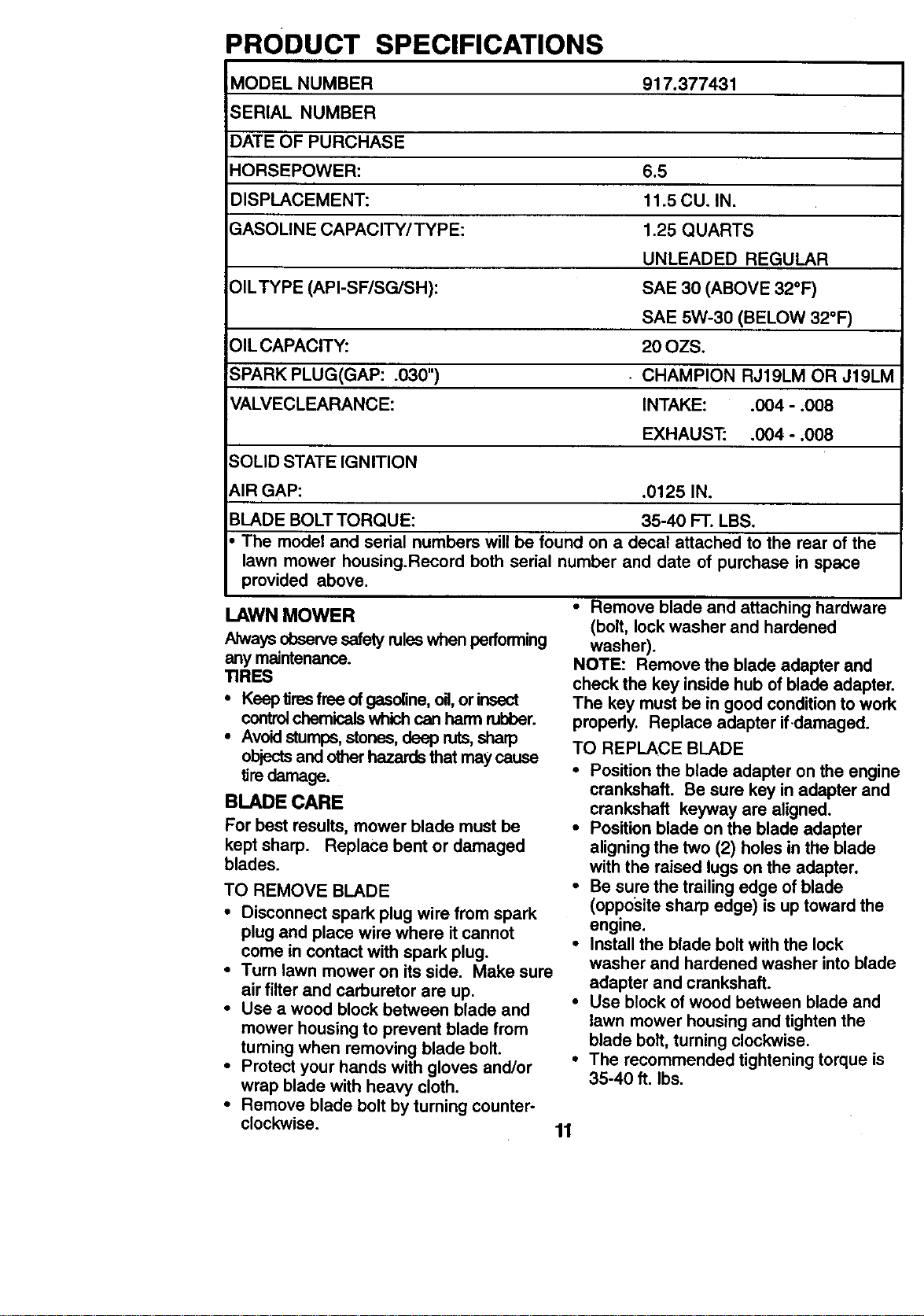
PRODUCT SPECIFICATIONS
MODEL NUMBER 917.377431
SERIAL NUMBER
DATE OF PURCHASE
HORSEPOWER: 6.5
DISPLACEMENT: 11.5 CU. IN.
GASOLINE CAPACITY/TYPE: 1.25 QUARTS
UNLEADED REGULAR
OILTYPE (API-SF/SG/SH): SAE 30 (ABOVE 32°F)
SAE 5W-30 (BELOW 32°F)
OIL CAPACITY: 20 OZS.
SPARK PLUG(GAP: .030") • CHAMPION RJ19LM OR J19LM
VALVECLEARANCE: INTAKE: .004 - .008
EXHAUS'E .004 - .008
SOLID STATE IGNITION
t_lR GAP: .0125 IN.
BLADE BOLT TORQUE: 35-40 FT. LBS.
The model and serial numbers will be found on a decal attached to the rear of the
lawn mower housing.Record both serial number and date of purchase in space
provided above.
LAWN MOWER
Always observe safety rules when performing
any maintenance.
TIRES
• Keep tires free of gasoline, oil, or insect
control chemicals which can harm rubber.
• Avoid stumps, stones, deep ruts,sharp
objects and other hazards that may cause
tim damage.
BLADE CARE
For best results, mower blade must be
kept sharp. Replace bent or damaged
blades.
TO REMOVE BLADE
• Disconnect spark plug wire from spark
plug and place wire where it cannot
come in contact with spark plug.
• Turn lawn mower on its side. Make sure
air filter and carburetor are up.
• Use a wood block between blade and
mower housing to prevent blade from
turning when removing blade bolt.
• Protect your hands with gloves and/or
wrap blade with heavy cloth.
• Remove blade bolt by turning counter-
clockwise.
• Remove blade and attaching hardware
(bolt, lockwasher and hardened
washer).
NOTE: Remove the blade adapter and
check the key insidehub of blade adapter.
The key must be in good conditionto work
properly. Replace adapter ifdamaged.
TO REPLACE BLADE
• Position the blade adapter on the engine
crankshaft. Be sure key inadapter and
crankshaft keyway are aligned.
• Position blade on the blade adapter
aligningthe two (2) holes in the blade
with the raised lugs on the adapter.
• Be sure the trailing edge of blade
(opposite sharp edge) is up toward the
engine.
• Install the blade boltwith the lock
washer and hardened washer intoblade
adapter and crankshaft.
• Use block of wood between blade and
lawn mower housing and tighten the
blade bolt,turning clockwise.
• The recommended tighteningtorque is
35-40 ft. Ibs.
11
IMPORTANT: Blade bolt is grade 8 heat
treated.
TO SHARPEN BLADE
NOTE: We do not recommend sharpening
blade - but ifyou do, be sure the blade is
balanced.
Care should be taken to keep the blade
balanced. An unbalanced blade will cause
eventual damage to lawn mower or
engine.
• The blade can be sharpened with a file
or on a grindingwheel. Do not attempt
to sharpen while on the mower.
• To check blade balance, drive a nail into
a beam or wall. Leave about one inch of
the straight nail exposed. Place center
hole of blade over the head of the nail.
If blade is balanced, it should remain in
a horizontal position. If either end of the
blade moves downward, sharpen the
heavy end until the blade is balanced.
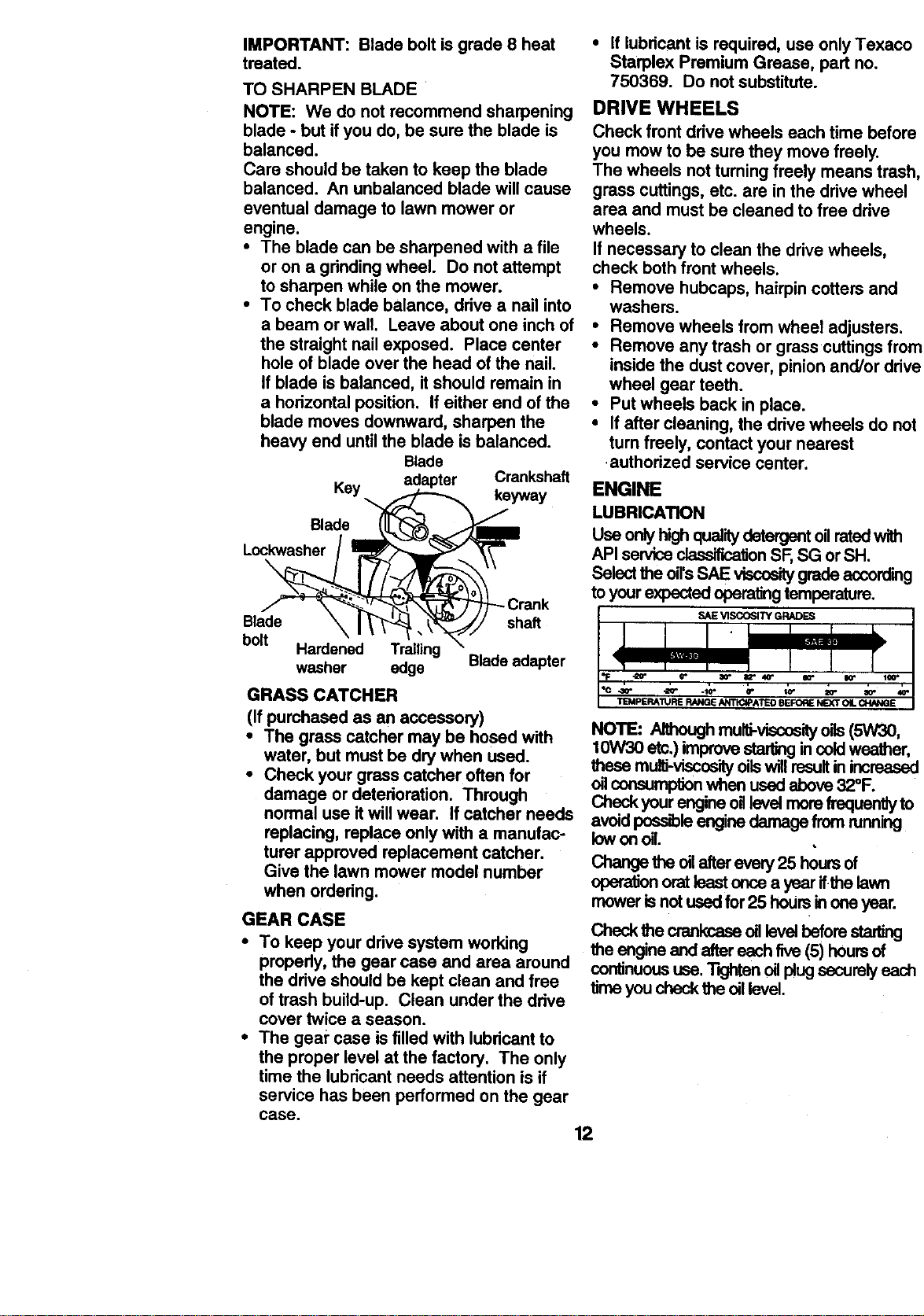
Blade
Key adapter Crankshaft
keyway
Blade
Lockwasher
\
Blade shaft
bolt
Hardened Trailing
washer edge Blade adapter
GRASS CATCHER
(If purchased as an accessory)
• The grass catcher may be hosed with
water, but must be dry when used.
• Check your grass catcher often for
damage ordeterioration. Through
normal use it will wear. If catcher needs
replacing, replace only with a manufac-
turer approved replacement catcher.
Give the lawn mower model number
when ordering.
GEAR CASE
• To keep your drive system working
propedy, the gear case and area around
the drive should be kept clean and free
of trash build-up. Clean under the drive
cover twice a season.
• The geal" case is filled with lubricant to
the proper level at the factory. The only
time the lubricant needs attention is if
service has been performed on the gear
case.
12
• If lubricant is required, use only Texaco
Starplex Premium Grease, part no.
750369. Do not substitute.
DRIVE WHEELS
Check front drive wheels each time before
you mow to be sure they move freely.
The wheels not turningfreely means trash,
grass cuttings, etc. are in the drive wheel
area and must be cleaned to free drive
wheels.
If necessary to clean the drive wheels,
check beth front wheels.
• Remove hubcaps, hairpin cotters and
washers.
• Remove wheels from wheel adjusters.
• Remove any trash or grass cuttings from
inside the dust cover, pinion and/or drive
wheel gear teeth.
• Put wheels back in place.
• If after cleaning, the drive wheels do not
turn freely, contact your nearest
authorized service center.
ENGINE
LUBRICATION
Use onlyhighqualitydetergentonratedwith
API serviceclsssitica_onSF, SG orSH.
Selectthe oil'sSAE viscositygradeaccording
toyourexpectedoperatingtemperature.
SAE VISCOSITY GRADES
TEMPERATURERANGEANTICIPATEDBEFORENEXTOILCHANGE
NOTE: Althoughmulti-viscosityoils(5W30,
10W30 etc.) improvestarlingincoldweather,
thesemulti-viscosityoilswillresultinincreased
_1consumptionwhen usedabove 32°F.
CheckyourengineoHlevelmerefrequentlyto
avoidpossibleenginedamage from running
lew en oil.
Changethe oilafterevery25 hoursof
operatienoratleast oncea year ifthe lawn
mowerlsnotusedfor25 hoursinene year.
Checkthe crankcaseonlsvoi befors_
the engineand aftereach five(5) hoursof
continuoususe."1"Kjhtanoilplugsecurelyeach
timeyou checkthe oil level.
TO CHANGE ENGINE OIL
NOTE: Before tipping lawn mower to drain
oil, drain fuel tank by running engine until
fuel tank is empty.
• Disconnect spark plug wire from spark
plug and place wire where itcannot
come in contact with spark plug.
• Remove engine oil cap; lay aside on a
clean surface.
• Tip lawn mower on itsside as shown
and drain oil into a suitable container.
Rock lawn mower back and forth to
remove any oil trapped inside of engine.
• Wipe off any spilled oil on lawn mower
and on side of engine.
• Fillengine with oil. Fillonly to the
"FULL" line on the dipstick. DO NOT
OVER FILL.
• Replace engine oil cap.
• Reconnect spark plug wire to spark
plug.
Container _
AIR RLTER
Your engine will not run propedy and may
be damaged by using a dirty air filter.
Replace the air filter every year, more
often if you mow in very dusty, dirty
conditions. Do not wash air filter.
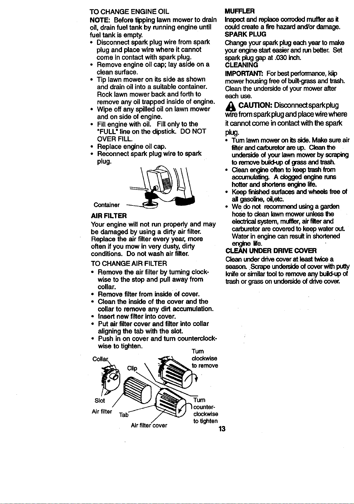
TO CHANGE AIR FILTER
• Remove the air filter by tuming clock-
wise to the stop and pull away from
collar.
• Remove filter from inside of cover.
• Clean the inside of the cover and the
collar to remove any dirt accumulation.
• Insert new fitter into cover.
• Put air filter cover and fitter into collar
aligningthe tab with the slot.
• Push in on cover and tum countemlock-
wise to tighten.
Tum
clockwise
Clip toremove
MUFFLER
Inspectand raplacecorrodedmuffleras it
couldcreatea fire hazardand/ordamage.
SPARK PLUG
Change yourspark plugeach year to make
yourenginest.arteasierand runbetter. Set
sparkplug gap at ,O3Oinch.
CLEANING
IMPORTANT: Forbestperfonmance,I_
mowerhousingfreeof built-grassand trash.
Cleanthe undersideofyour mowerafter
each use.
_lb CAUTION: Dks_nnc:_-'tsparkplug
wire from spark plug and place wire where
itcannot come in contact with the spark
plug.
• Turnlawn moweronitsside. Make sureair
filterand carburetorare up. Cleanthe
undersideofyour lawnmowerby scraping
to rernovebuild-upof grassand trash.
• Clean engineoftonto kseptrashfrom
accumulating.A doggedengineruns
hotterand shortensenginelife.
• Ksep finisi'_l surfaces and wheeb free _
all gasorw_, oil,etc.
• Wedonot recomrnendusingagarden
hoseto clean lawnmowerunlessthe
electricalsystem,muffler,airfilterand
carburetorare coveredto keep water out.
Water in enginecan resultin shortensd
engine life.
CLEAN UNDER DRIVE COVER
Clean underddvecoverat least twicea
season..Scrape undersideof coverwithputty
knifeor similartoolto removeanybuild-up of
trashor grassonundersideof drivecover.
Slot
Air filter
Tum
Tab clockwise
totighten
Airtilter cover 13
CAUTION:Beforeperformingany
serviceandadjustments:
• Release control bar and stop engine.
• Make sure the blade and all moving
parts have completely stopped.
• Disconnect spark plug wire from spark
plug and place where it cannot come
in contact with plug.
LAWN MOWER
TO ADJUST cUTrlNG HEIGHT
See "TO ADJUST CUTTING HEIGHT" in
the Operation section of this manual.
DISCHARGE GUARD
The discharge guard, attached to the
discharge opening of your lawn mower, is
provided to prevent the possibilityof injury
resulting from objects being thrown out of
the discharge opening intothe operator
mowing position. Ifthe discharge guard
becomes damaged, it should be replaced.
REAR DEFLECTOR
The rear deflector, attached between the
rear wheels of your mower, is provided to
minimize the possibilitythat objects will be
thrown out of the rear of the mower into
the operator mowing position. If the
deflector becomes damaged, itshould be
replaced.
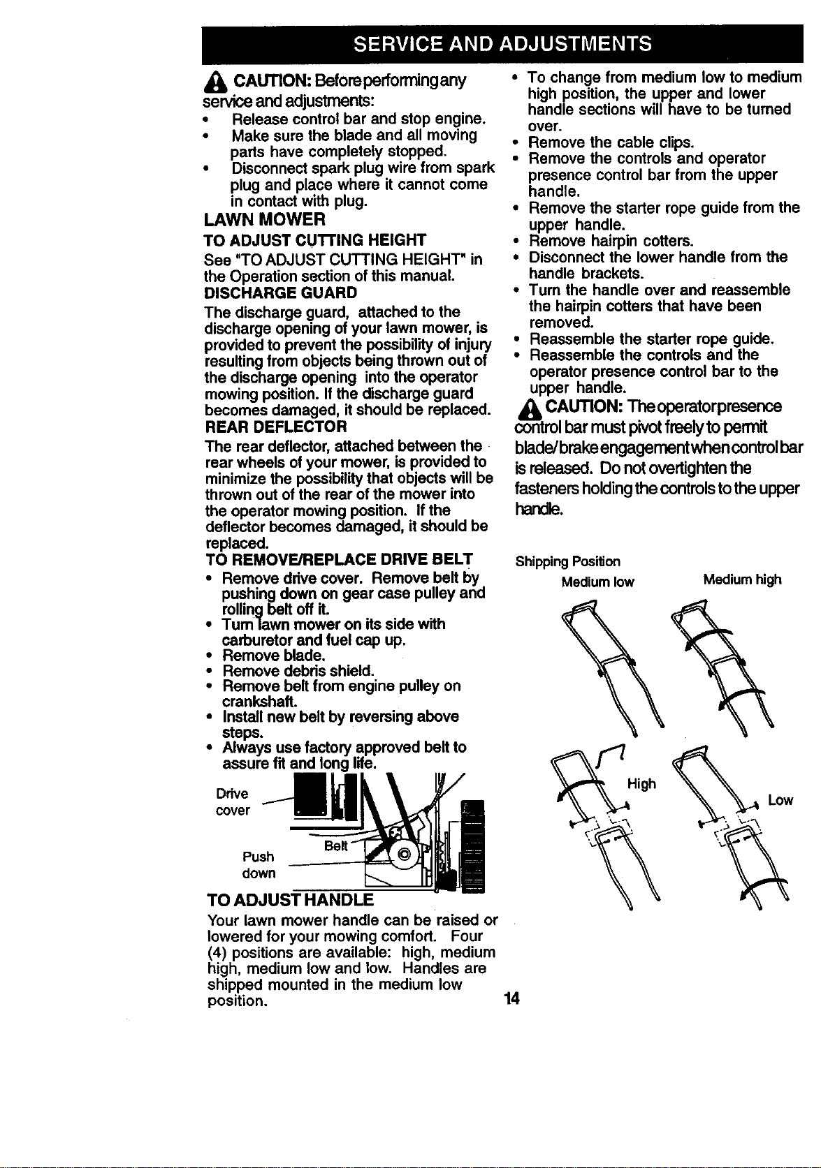
TO REMOVE/REPLACE DRIVE BELT
i emove drive cover. Remove belt by
pushing down on gear case pulley and
rollingbelt off it.
Tum lawn mower on its side with
carburetor and fuel cap up.
• Remove blade.
• Remove debris shield.
• Remove belt from engine pulley on
crankshaft.
• Install new belt by reversing above
steps.
• Always use factory approved belt to
assure fit and long life.
Drive
cover
Push
down
TO ADJUST HANDLE
Your lawn mower handle can be raised or
lowered for your mowing comfort. Four
(4) positions are available: high, medium
high, medium low and low. Handles are
shipped mounted in the medium low
position.
• To change from medium low to medium
high position, the upper and lower
handle sections will have to be turned
over.
• Remove the cable clips.
• Remove the controls and operator
presence control bar from the upper
handle.
• Remove the starter rope guide from the
upper handle.
• Remove hairpin cotters.
• Disconnect the lower handle from the
handle brackets.
•Tum the handle over and reassemble
the hairpin cotters that have been
removed.
• Reassemble the starter rope guide.
• Reassemble the controls and the
operator presence control bar to the
upper handle.
_, CAUTION: Theoperatorpresence
control bar must pivotfreely to permit
blade/brake engagement when control bar
isreleased. Do not overtighten the
fasteners holdingthe controls tothe upper
handle.
Shipping Position
Medium low
Medium high
High
Low
14
• To change from medium low to high
position only the upper handle section
will have to be tumed over.
• To change from medium low to low
position, only the lower handle section
will have to be turned over.
remove
Lower handle
Handle bracket
Hairpin cotter
ENGINE
ENGINE SPEED
Your engine speed has been factory set.
Do not attempt to increase engine speed
or it may result in personal injury. If you
believe that engine is runningtoo fast or
too slow, take your mower to an authorized
service center for repair and adjustment.
IMPORTANT: Never tamper with the
engine govemor, which isfactory set for
the proper engine speed. Overspeeding
the engine above the factory high speed
scan be dangerous. If you think the
engine-govemed high speed needs
adjusting, contact your nearest authorized
service center, which has proper equip-
ment and experience to make any
necessary adjustments.
CARBURETOR
Your carburetor has a non-adjustable fixed
mainjet for mixturecontrol. Ifyour engine
does not operate properly due to sus-
pected carburetor problems, take your
lawn mower to an authorized service
center for repair and/or adjustment.
Immediatelyprepareyourlawn mowerfor
storageat the end ofthe seasonor ifthe unit
willnotbe usedfor 30 daysor more.
LAWN MOWER
When lawn mower isto be storedfor a period
oftime,clean itthoroughly,removeall dirt,
grease,leaves,etc. Storeina clean,dryarea.
• Clean entirelawn mower(See "CLEAN-
ING" inthe Maintenancesectionofthis
manual).
• Lubricateas shown inthe Maintenance
sectionof thismanual.
• Be sure that allnuts,bolts,screws,and pins
are securelyfastened. Inspect moving
partsfordamage, breakageand wear.
Replace if necessary.
• Touch up all rustedor chippedpaint
surfaces;sand lightlybeforepainting.
HANDLE
You can fold your lawn mower handle for
storage.
• Squeeze the bottom ends of the lower
handle toward each other until the lower
handle dears the handle bracket, then
move handle forward.
• Loosen upper handle mounting belts
enough to allow upper handle to be folded
back.
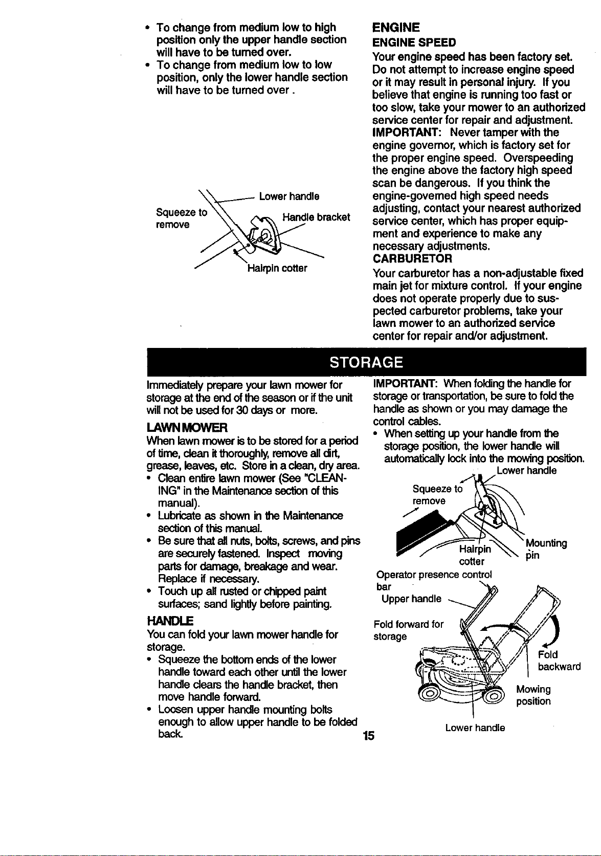
IMPORTANT: When folding the handle for
storage or transportation, be sure to fold the
handle as shown or you may damage the
control cables.
• When setting up your handle from the
storage position, the lower handle will
automatically lock into the mowing position.
Lower handle
remove
Hairpin _in
cotter
Operatorpresencecontrol
bar
Upperhandle ....._/,_.......,_2//4/_"*P)_"
Foldforwardfor __ ___... _
&/TJ
storage __ ___
t_'-'_'-'_-'_ ,//I Fold
- Mowing
"_ position
Lower handle
15
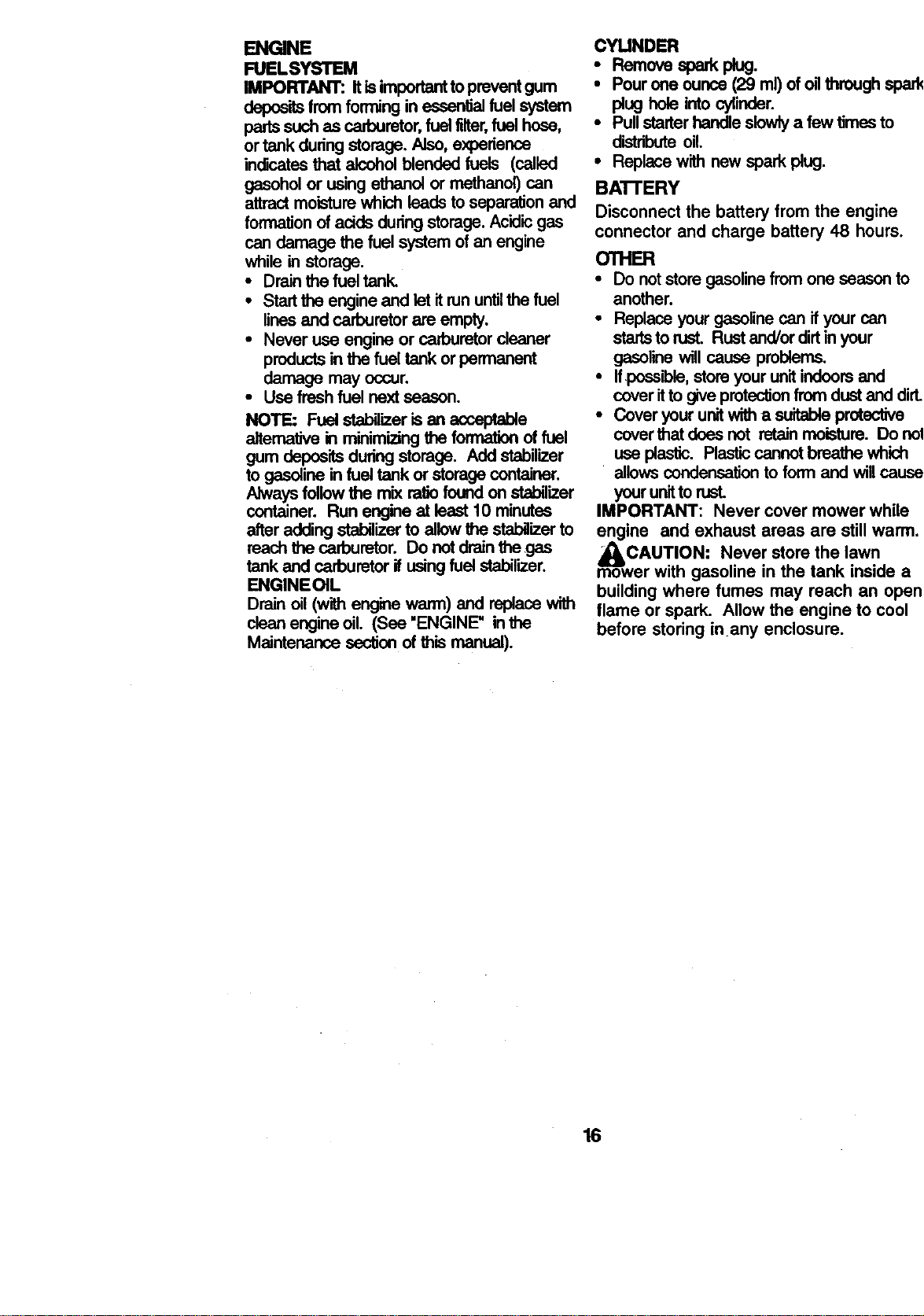
ENGINE
FUELSYSTEM
IMPORTANT: It isimportant to prevent gum
deposits from forming in essential fuel system
parts such as carburetor, fuel filter,fuel hose,
or tank during storage. Also, experience
indicates that alcohol blended fuels (called
gasohol or using ethanol or methanol) can
attract moisture which leads to separ'_on and
formation of acids during storage. Ac'_licgas
can damage the fuel system of an engine
while in storage.
• Drain the fuel tank.
• Start the engine and let it run untilthe fuel
lines and carburetor are empty.
• Never use engine or carburetor cleaner
products in the fuel tank or permanent
damage may occur.
• Use fresh fuel next season.
NOTE: Fuel stabilizer is an acceptable
aitemative in minimizing the formation of fuel
gum deposits during storage. Add stabilizer
to gasoline in fuel tank or storage container.
Always follow the mix ratio found on stabilizer
container. Run engine at least 10 minutes
after adding stabilizer to allow the stabilizer to
reach the carburetor. Do not drain the gas
tank and carburetor if using fuel stabilizer.
ENGINEOIL
Drain oil (with engine warm) and replace with
clean engine oil. (See "ENGINE" in the
Maintenance section of this manual).
CYUNDER
• Removespa p g.
• Pour one ounce(29 mi) ofoilthrough spark
plughole intocylinder.
• Pullstarterhandleslowlya few timesto
distributeoil.
• Replacewith new spark plug.
BA'I-rERY
Disconnect the battery from the engine
connector and charge battery 48 hours.
OTHER
• Do notstoregasolinefromone seasonto
another.
• Replaceyour gasolinecan if your can
startsto rust. Rustend/or dirtinyour
gasolinewill cause problems.
• If,possible,store yourunitindoorsend
coverittogive protectionfromdustend dirt.
• Coveryour unitwitha suitableprotective
coverthat doesnot retainmoisture. Do not
use plastic. Plasticcannotbreathe which
• allowscondensationtoform and will cause
yourunittorust.
IMPORTANT: Never cover mower while
engine and exhaust areas are stillwarm.
_CAUTION: Never store the lawn
mower""with gasoline in the tank inside a
building where fumes may reach an open
flame or spark. Allow the engine to cool
before storing inany enclosure.
16
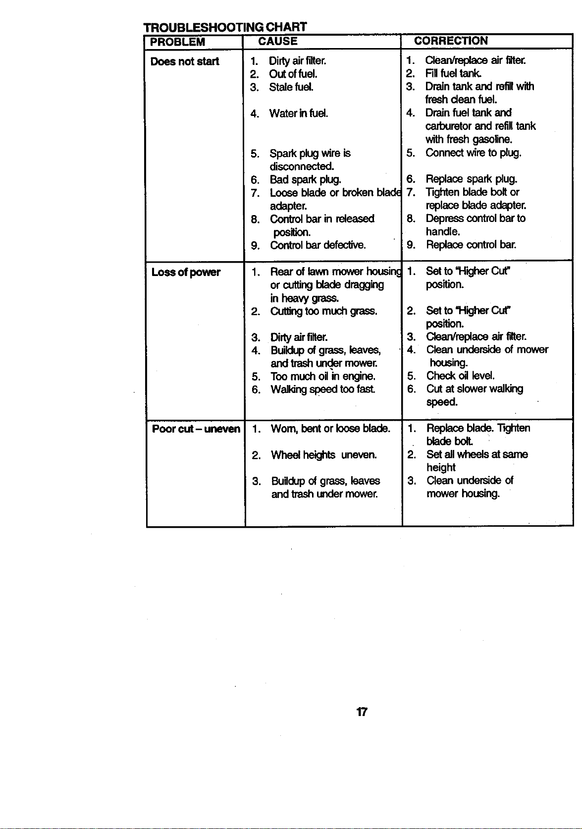
TROUBLESHOOTING CHART
PROBLEM CAUSE CORRECTION
Does not start
Lossofpower
Poor out- uneven
1. Dirtyairfilter.
2. Out offuel.
3. Stalefuel.
4. Water infuel.
5. Spark plugwire is
disconnected.
6. Bad spa_ plug.
7. Loose blade or brokenblack
adapter.
8. Controlbar in released
pos o..
9. Controlbar defective.
1. Rear of lawnmower heusin
or cuttingblade dragging
in heavy grass.
2. Cuttingtoomuchgrass.
3. Dirtyairfilter.
4. Buildupofgrass, leaves,
and trashun_r mower.
5. Toomuchoil in engine.
6. Walkingspeed toofast.
1. Worn, bentor Ioeseblade.
2. Wheel heights uneven.
3. Buildupof grass,leaves
and trashundermower.
1. Clean/replace air filter,
2. Fillfuel tank.
3. Draintank and refillwith
freshdean fuel.
4. Drainfuel tank and
carburetorand refilltank
withfreshgasoline.
5. Connectwire tOplug.
6. Replace spark plug.
7. Tighten blade boltor
replaceblade adapter.
8. Depress controlbar to
handle.
i 9. Replace controlbar.
1. Set to =HigherCut"
position.
2. Set to =Higher Cut"
position.
3. Clean/replace air _er.
4. Clean underside of mower
housing.
5. Check ell level.
6. Cut at slower walking
speed.
1. Replaceblade. "l-_jhten
blade boll
2. Set allwheelsat same
height
3. Clean undersideof
mower housing.
17
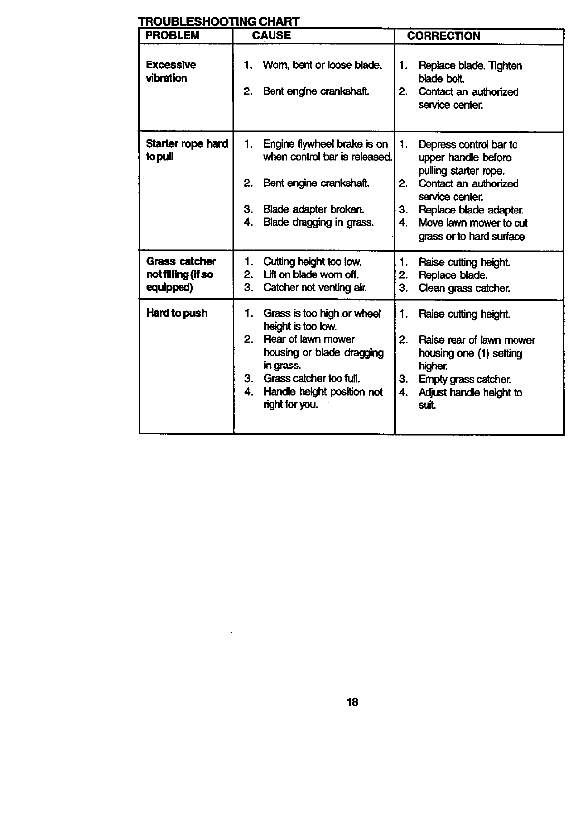
TROUBLESHOOTING CHART
PROBLEM CAUSE CORRECTION
Excessive
vibration
Starter rope hard
topull
1. Replace blade."Rghten
bladebolt.
2. Contactan authorized
servicecenter.
1. Wom, bentor looseblade.
2. Bentenginecrankshaft.
1. Engineflywheelbrake ison
when controlbar is released.
2. Bentenginecrankshaft.
3. Bladeadapter brokan.
4. Bladedraggingin grass.
Cuttingheighttoo low.
Liftonbladeworn off.
Catchernotventingair.
Grassis toohighor wheel
height is toolow.
2. Rear of lawnmower
housingor blade drag_ng
ingrass.
3. Grasscatchertoofull.
4. Handle height positionnot
_ht foryou. •
1. Depresscontrolbarto
upper handle before
pullingstarter rope.
2. Contactan authorized
service center.
3. Replace blade adapter.
4. Move lawnmowerto cut
grassorto hardsurface
Gross catcher 1. 1. Raise cuttingheighL
notftlling0fso 2. 2. Replace blade.
equipped) 3. 3. Clean grasscatcher.
Hardto push 1. 1. Raise cuttingheight.
2. Raise rear of lawn mower
housing ore (1) setting
higher.
3. Emptygrasscatcher.
4. Adjusthandleheightto
suit.
18
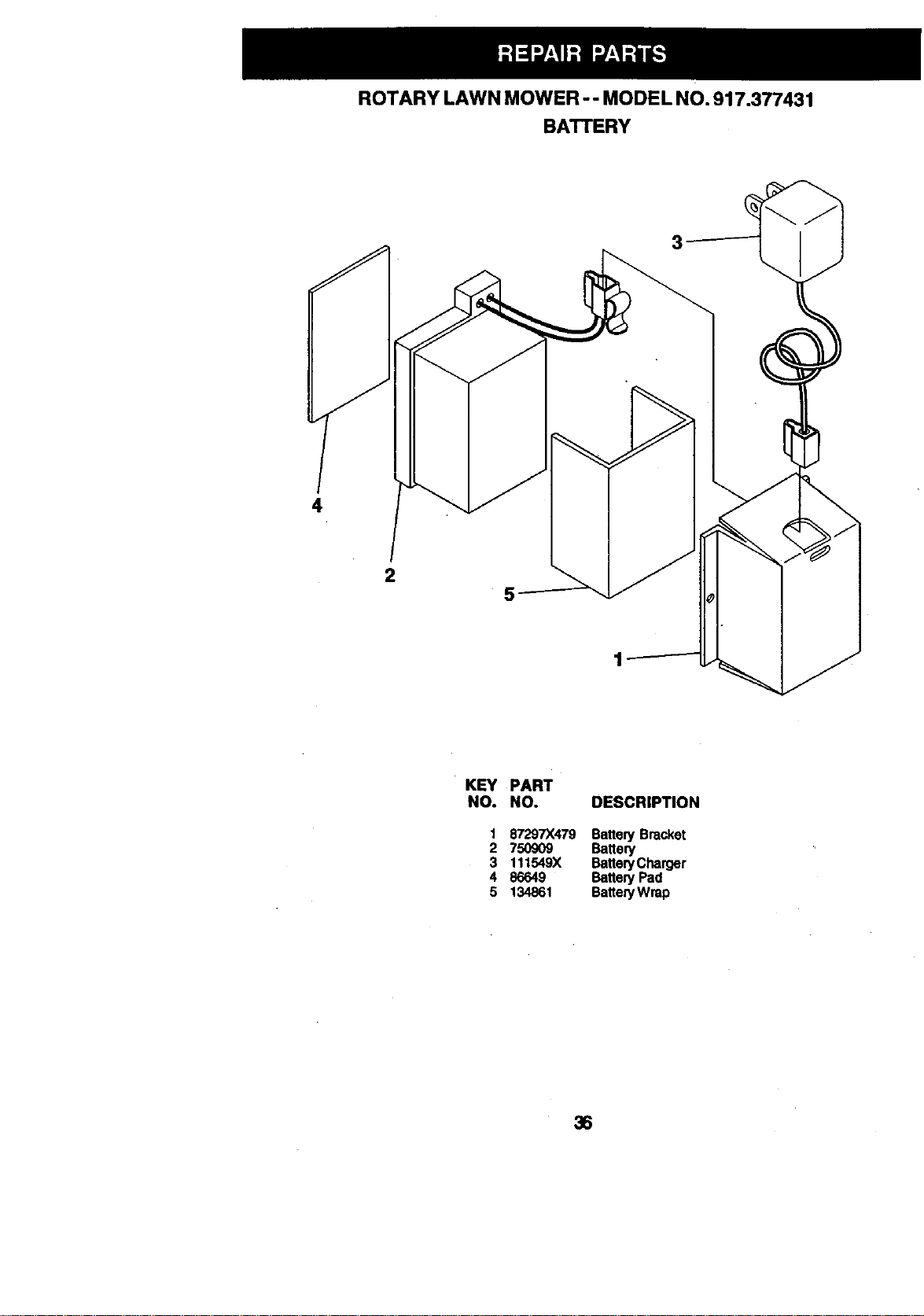
ROTARY LAWN MOWER-- MODEL NO. 917.377431
BATrERY
3
4
2
5
KEY PART
NO. NO. DESCRIPTION
1 87297X479 Batten/Bracket
2 750909 Battery
3 111549X Battery Charger
4 86649 Batten/Pad
5 134861 Batten/Wrap
36
I
ROTARY LAWN MOWER -- MODEL NO. 917.377431
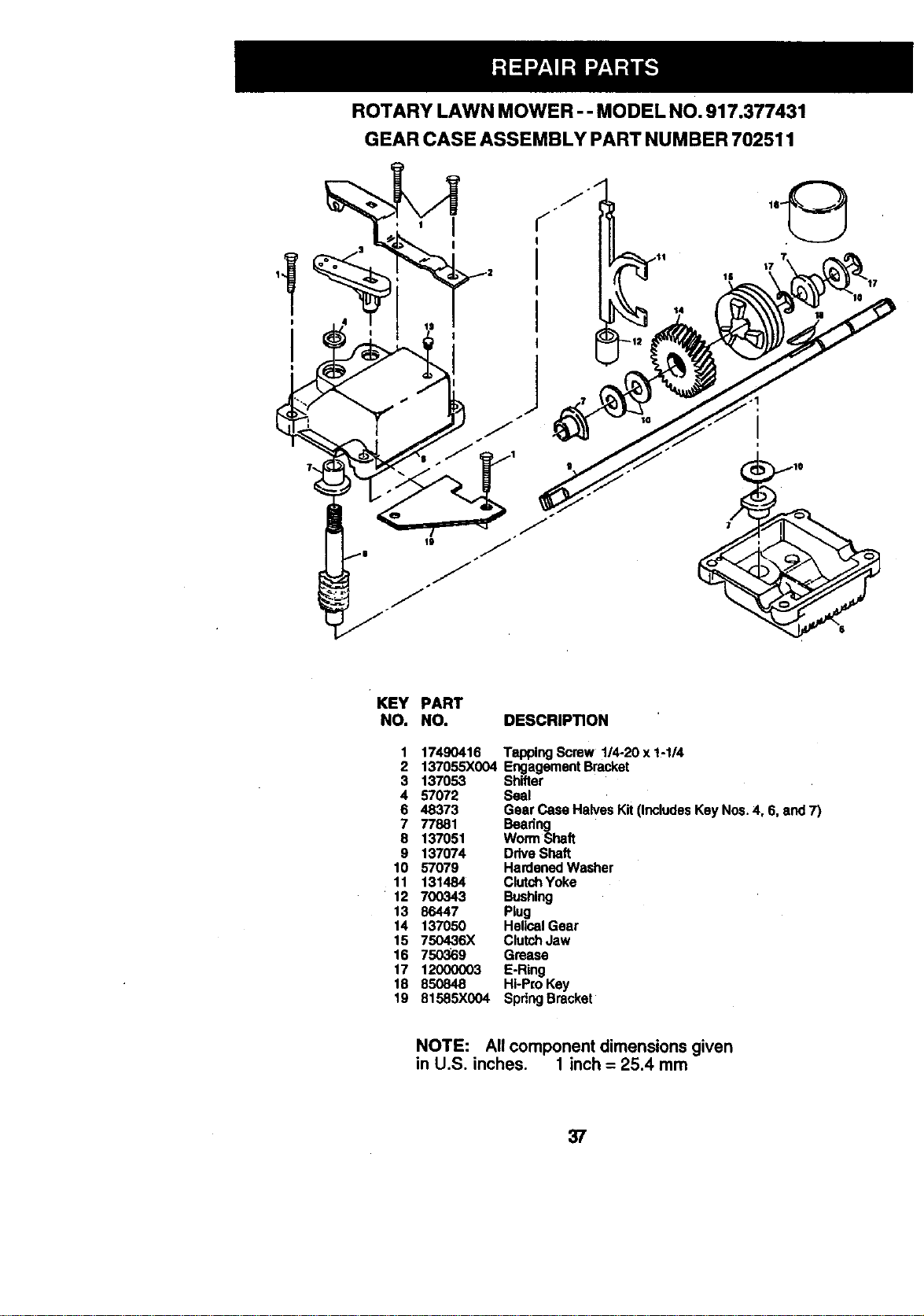
GEAR CASE ASSEMBLY PART NUMBER 702511
17
I|
KEY PART
NO. NO. DESCRIPTION
1 17490416 Tapping Screw 1/4-20 x 1-1/4
2 137055X004 Engagement Bracket
3 137053 Shifter
4 57072 Seal
6 48373 Gear Case Halves Kit (Includes Key Nos. 4, 6, and 7)
7 77881 Bearing
8 137051 Worm Shaft
9 137074 Ddve Shaft
10 57079 Hardened Washer
11 131484 Clutch Yoke
12 700343 Bushing
13 86447 Plug
14 137050 Helical Gear
15 750436X Clutch Jaw
16 750369 Grease
17 12000003 E-Ring
18 850848 Hi-Pro Key
19 81585X004 SpdngBracket
NOTE: All component dimensions given
in U.S. inches. 1 inch = 25.4 mm
37
38
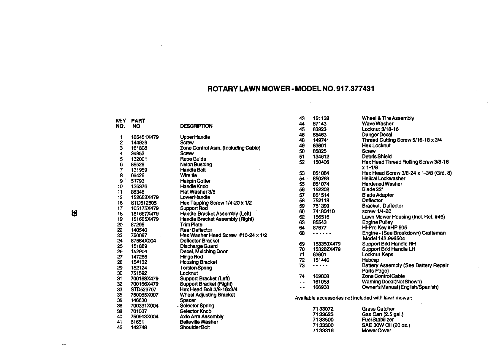
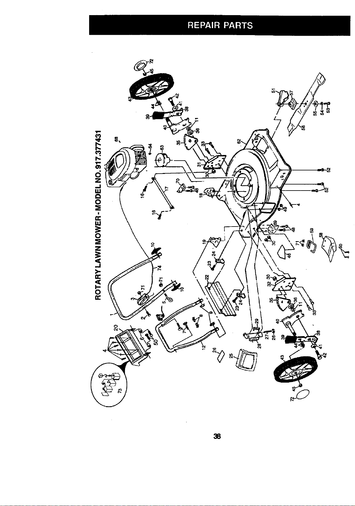
ROTARY LAWN MOWER- MODEL NO.917.377431
KEY
NO,
1
2
3
4
5
6
7
8
9'
10
11
12
16
17
18
19
20
22
23
24
25
26
27
28
29
30
31
32
33
35
36
38
39
40
41
42
PART
NO
165451X479
144929
161808
36953
132001
85529
131959
66426
51793
136376
88348
152653X479
STD512505
165175X479
151667X479
151665X479
87295
140540
750097
87584X004
151889
152904
147286
154132
152124
751592
700168X479
700166X479
STD523707
750085X007
146630
700331X004
701037
750913X004
61651
142748
43 151138
DESCRI'PI"K)N 44 57143
45 83923
UpparHandle 46 85463
48 149741
Screw 49 63601
Zone ControlAsm. (IncludingCable) 50 85825
Screw 51 134612
RopeGuide
NylonBushing 52 150406
HandleBolt
Wire tie 53 851084
54 850263
HairpinCotter
HandleKnob 55 851074
Flat Washer 3/8 56 152202
LowerHandle 57 851514
Hex Tapping Screw 1/4,20 x 1/2 58 752118
SupportRod 59 751399
Handle BracketAssembly (Left) 60 74180410
Handle Bracket Assembly(Right) 62 156516
TdmPlata 63 85543
Rear Deflector 64 87677
Hex Washer Head Screw #10-24 x 1/2 68 ......
Deflector Bracket
DischargeGuard 69 153350X479
Decal, MulchingDoor 70 153282X479
71 63601
HingeRod 72 151440
HousingBracket
TorsionSpdng 73 .....
Locknut
SupportBracket (Left) 74 169808
SupportBracket(Right) - - 161058
Hex Head Bolt3/8-16x3/4 - - 166938
Wheel AdjustingBracket
Spacer
• SelectorSpdng
SelectorKnob 71 33072
Axle Arm Assembly 71 33623
BsllevilleWasher 71 33500
ShoulderBOlt 71 33300
71 33316
Wheel &Tire Assembly
WaveWasher
Locknut 3/18-16
DangerDecal
Thread CuttingScrew 5/16-18 x 3/4
Hex Locknut
Screw
DebdsShield
Hex Head Thread RollingScrew 3/8-16
x 1-1/8
Hex Head Screw 3/8-24 x 1-3/8 (Grd. 8)
HelicalLockwasher
HardenedWasher
Blade22"
BladeAdapter
Deflector
Bracket, Deflector
screw 1/4-20
LawnMower Housing (Incl.Ref. #46)
EnginePulley
Hi-Pro Key#HP 505
Engine- (See Breakdown) Craftsman
Model 143.996504
SupportBrktHandle RH
SupportBrk'tHandle LH
LocknutKeps
Hubcap
BatteryAssembly (See Battery Repair
Parts Page)
Zone ControlCable
Waming Decal(Not Shown)
Owner's Manual(EnglisWSpanlsh)
Available accessories not included with lawn mower:.
Grass Catcher
Gas Can (2.5 gal.)
FuelStabilizer
SAE 30W Oil (20 oz.)
MowerCover
ROTARY LAWN MOWER- MODEL NO. 917.377431
24
22
\
21
29
I
I
r
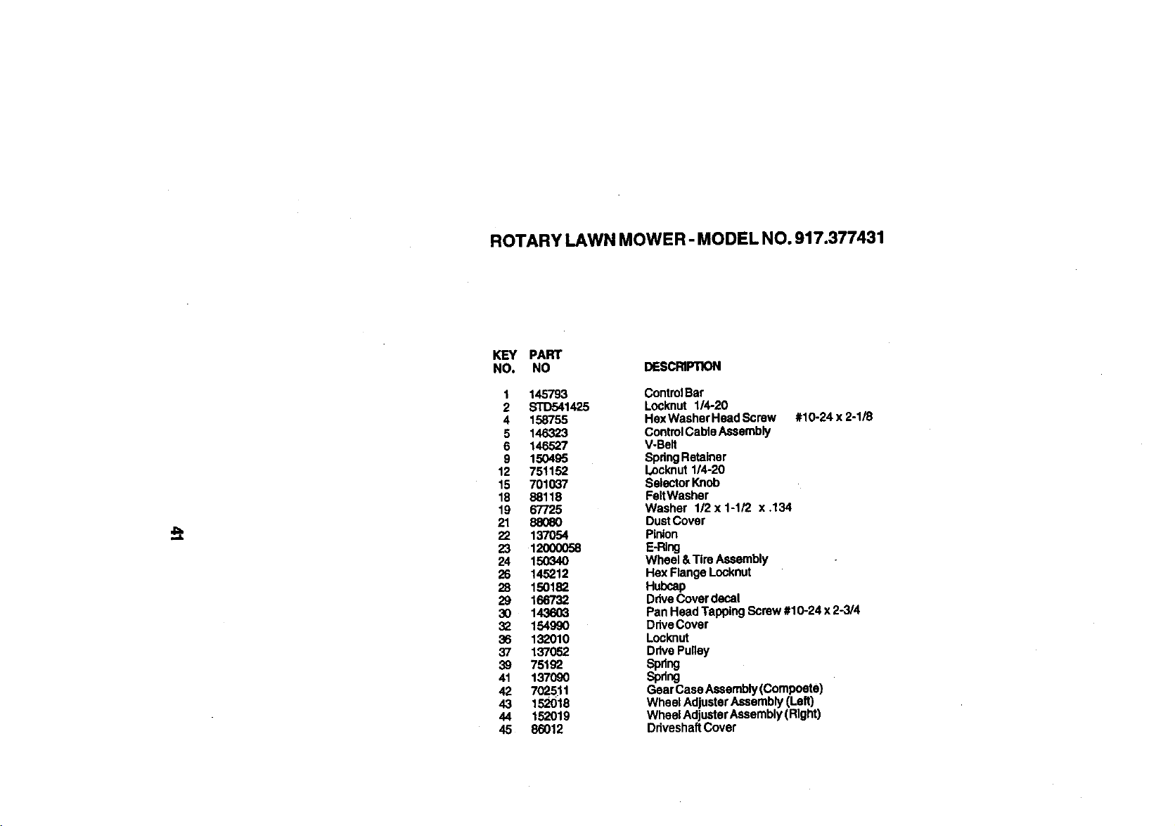
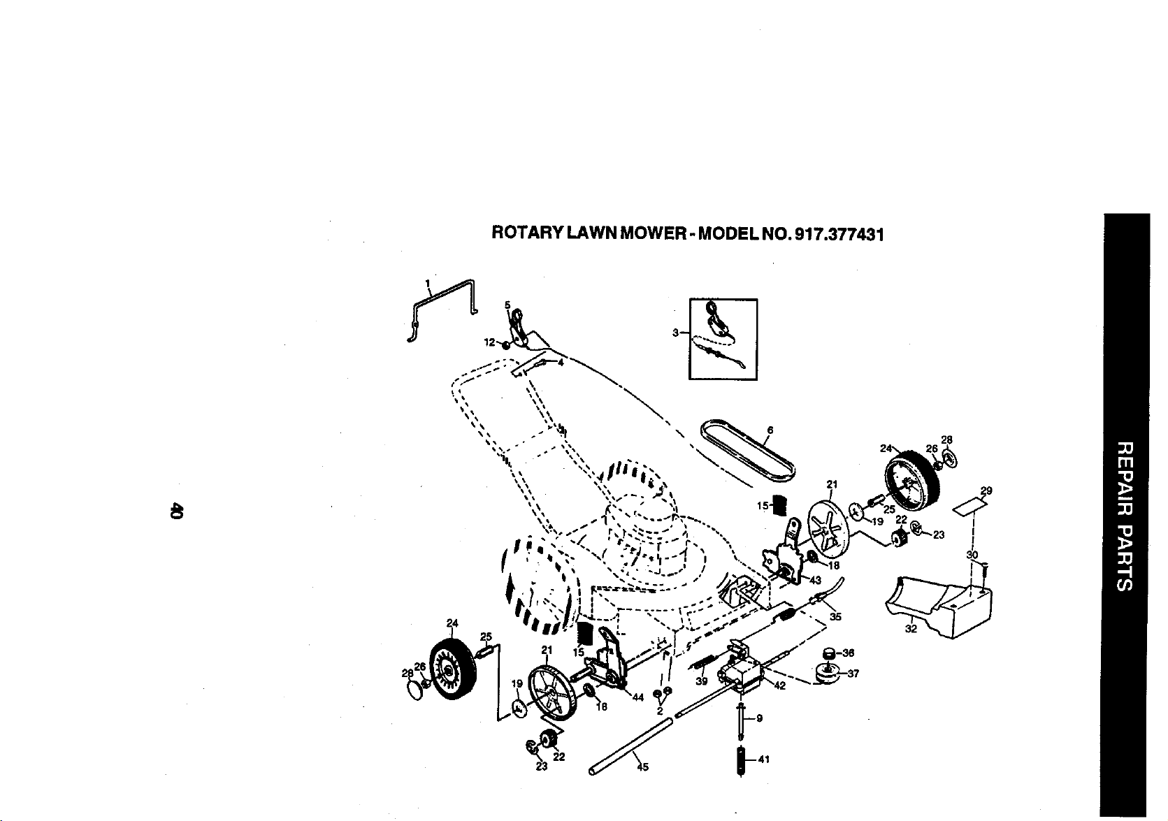
ROTARY LAWN MOWER- MODEL NO. 917.377431
KEY PART
NO. NO DESCRIPTION
1 145793
2 STD541425
4 158755
5 146323
6 146527
9 150495
12 751152
15 701037
18 88118
19 67725
21 88080
22 137054
23 12O00058
24 150340
26 145212
28 150182
29 166732
3O 143603
32 154990
36 132010
37 137052
39 75192
41 137090
42 70P.511
43 152O18
44 152019
45 86012
ControlBar
Locknut 1/4-20
HexWasher HeadScrew #10-24 x 2-1/8
ControlCableAssembly
V.Belt
SpringRetainer
Locknut1/4-20
SelectorKnob
FeltWasher
Washer 1/2 x 1-1/2 x .134
DustCover
Pinion
E-P_ng
Wheel &Tire Assembly
Hex Flange Locknut
Hubcap
DdveCover decal
Pan Head Tapping Screw #10-24 x 2-3/4
DriveCover
Locknut
DdvePulley
Spdng
Spltng
Gear Case Assembly(Compoete)
Wheel AdusterAssembly(Left)
Wheel AdjusterAssemb y (Right)
DdveshaftCover
CRAFTSMAN 4-CYCLE ENGINE MOOEL NUMBER 143.996504
119
125
l
_74172
73
195
245
25O
42
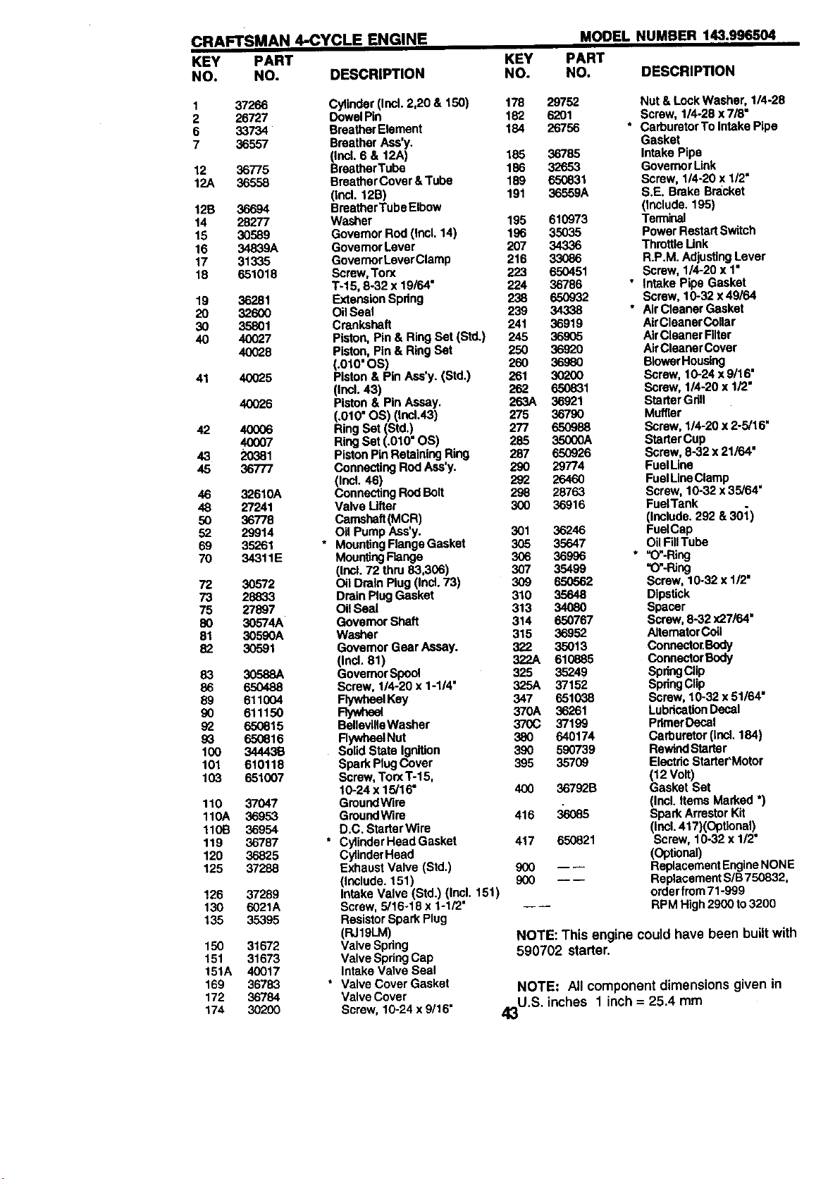
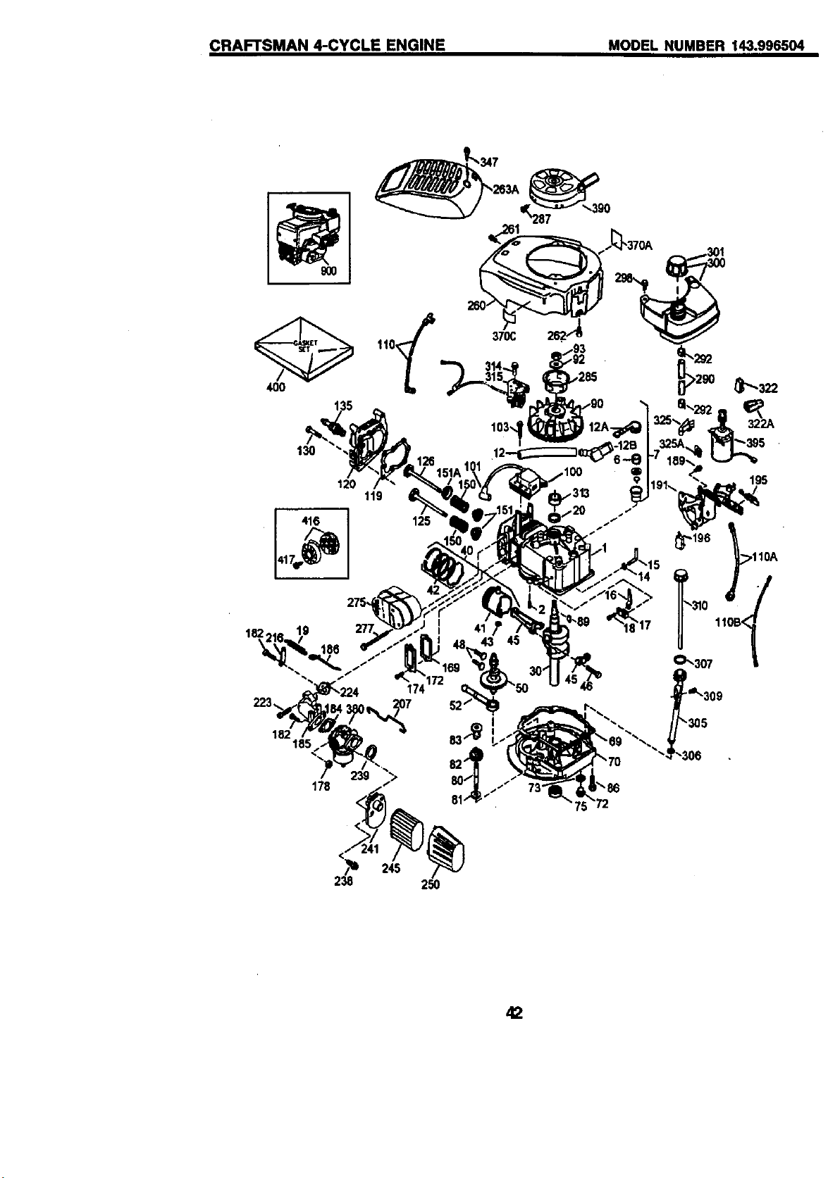
CRAFTSMAN 4-CYCLE ENGINE
KEY PART
NO. NO. DESCRIPTION
MODEL NUMBER 143.996504
KEY PART
NO. NO. DESCRIPTION
1 37266 Cylinder (Incl, 2,20 & 150)
2 26727 DowelPin
6 33734 BreatherElement
7 36557 Breather Ass'y.
(Incl. 8 & 12A)
12 36775 BreatherTubs
12A 36558 Breather Cover &Tube
(Incl. 12B)
12S 36694 BreatherTube Elbow
14 28277 Washer
15 30589 Governor Rod (Incl. 14)
16 34839A Govemor Lever
17 31335 Governor LeverClamp
18 651018 Screw, Torx
T-15, 8-32 x 19/64 =
19 36261 ExtensionSpring
20 32600 Oil Seal
30 35801 Crankshaft
40 40027 Piston, Pin & Ring Set (Std.)
40028 Piston, Pin& Ring Set
(.010' OS)
41 40025 Piston & Pin Ass'y. (Std.)
(Incl. 43)
40026 Piston & Pin Assay.
(.010" OS) (Incl.43)
42 40006 Ring Set (Std.)
40007 Ring Set (.010" OS)
43 20381 Piston Pin RetainingRing
45 36777 Connecting Rod Ass'y.
(incl. 46)
46 32610A Connecting RodBolt
48 27241 Valve Lifter
50 36778 Camshaft(MCR)
52 29914 Oil Pump Ass'y.
69 35261 • MountingFlange Gasket
70 34311E MountingFlange
(Incl. 72 thru 83,306)
72 30572 Oil Drain Plug (Ind. 73)
73 28833 DrainPlug Gasket
75 27897 OilSeal
80 30b'74A Governor Shaft
81 30590A Washer
82 30591 Governor Gear Assay.
(Incl. 81)
83 30588A GovernorSpool
86 650488 Screw. 1/4-20 x 1-1/4"
89 611004 FlywheelKey
90 611150 FI_
92 650815 BelleviltaWasher
93 650816 RywheelNut
100 34443B Solid State Ignition
101 610118 Spark Plug Cover
103 651007 Screw, Torx T-15,
10-24 x 15/16"
110 37047 GroundW]re
110A 36953 GroundWire
110B 36954 D.C. StarterWire
119 36787 * CyfinderHead Gasket
120 36825 CylinderHead
125 37288 Exhaust Valve (Std.)
(Include. 151)
126 37289 Intake Valve (Std.) (Incl. 151)
130 6021A Screw, 5/16-18 x 1-1/2"
135 35395 ResistorSpark Plug
(RJ19LM)
150 31672 Valve Spflng
151 31673 Valve SpringCap
151A 40017 Intake Valve Seal
169 36783 * Valve Cover Gasket
172 36784 ValveCover
174 30200 Screw, 10024x 9/16"
178 29752 Nut & LockWasher, 114-28
182 6201 Screw, 1/4-28 x 7/8"
184 26756 * Carburetor To Intake Pipe
Gasket
185 36785 Intake Pipe
186 326.53 GovemorLink
189 650831 Screw, 1/4-20 x 1/2"
191 36559A S,E, Brake Bracket
(Include. 195)
195 610973 Terminal
196 35035 Power RestartSwitch
207 34336 ThrottleUnk
216 33086 R.P,M. AdjustingLever
223 650451 Screw, 1/4-20 x 1"
224 36786 " Intake Pipe Gasket
238 650932 Screw, 10o32x49/64
239 34338 * Air Cleaner Gasket
241 36919 AirCleanerCollar
245 36905 AirCleaner Rltar
250 36920 AirCleaner Cover
260 36960 BlowerHousing
261 30200 Screw, 10024x 9/16'
262 650831 Screw, 1/4-20 x 1/2"
263A 36921 StarterGrill
275 36790 Muffler
277 650988 Screw, 1/4-20x2-5/16"
285 35000A StarterCup
287 650926 Screw, 8-32 x 21/64'
290 29774 Fuel Line
292 26460 Fuel LineClamp
298 28763 Screw, 10-32 x35/64"
300 36916 FueITank
(Include. 292 & 30"1)
301 36246 FueICap
305 35647 OilFillTube
306 36996 * "O'-Ring
307 35499 "Ct'-Ring
309 650562 Screw, 10-32 x 1/2"
310 35648 Dipstick
313 34080 Spacer
314 650767 Screw, 8-32 x27/84"
315 36952 AlternatorCoil
322 35013 Connecto[Scdy
322A 610885 ConnectorBody
325 35249 SpdngClip
325A 37152 SpdngClip
347 651038 Screw, 10032x 51/64"
370A 36261 LubricationDecal
370C 37199 PdmerDecal
380 640174 Carburetor (Incl. 184)
390 590739 RewindStartar
395 35709 ElectricStarter_Motor
(I 2 Volt)
400 36792B Gasket Set
(Incl. Items Marked *)
416 :_o088 Spark ArrestorKit
(Incl.417)(Optional)
417 650821 Screw, 10-32 x 1/2"
(Optional)
900 -- -- ReplacementEngineNONE
900 ---- Replacement S/B750832,
orderfrom71-999
-- -- RPM High2900 to3200
NOTE: This engine could have been built with
590702 starter.
NOTE: All component dimensions given in
43U.S, inches 1 inch = 25.4 mm
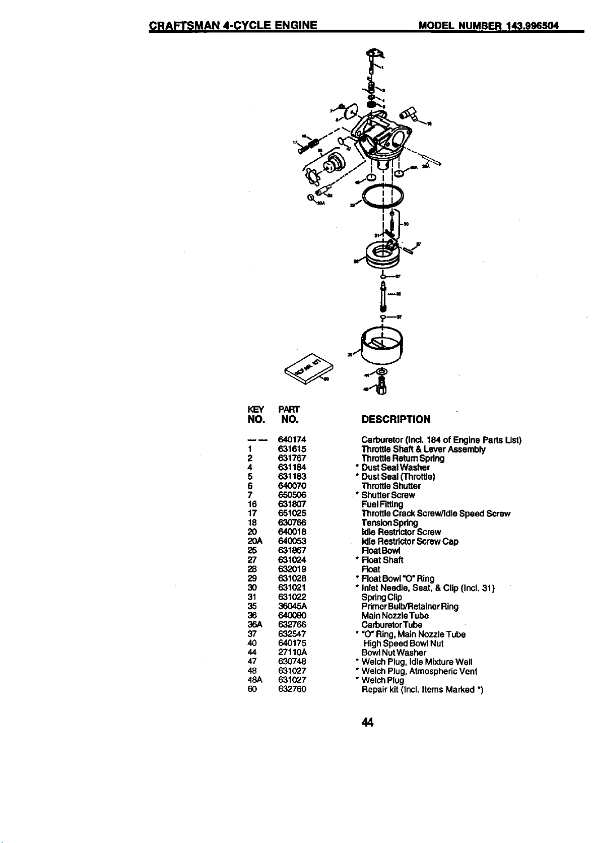
CRAFTSMAN 4-CYCLE ENGINE MODEL NUMBER 143.996504
KEY PART
NO. NO.
---- 640174
1 631615
2 631767
4 631184
5 631183
6 640070
7 650506
16 631807
17 651025
18 630766
20 640018
20A 64O053
25 631867
27 631024
28 632019
29 631028
30 631021
31 631022
35 36045A
36 64O08O
36A 632766
37 632547
40 640175
44 27110A
47 630748
48 631027
48A 631027
60 632760
DESCRIPTION
Carburetor (Incl. 184of Engine Parts Ust)
Throttle Shaft & Lever Assembly
ThrottleRetum Spdng
* DustSeal Washer
* DustSeal (Throttle)
Throttle Shutter
* ShutterScrew
FuelFitting
ThrottleCrock Screw/Idle Speed Screw
TensionSpdng
Idle Restdctor Screw
Idle RestrlctorScrew Cap
FloatBowl
* Float Shaft
Float
• FloatBowl"O" Ring
• Inlet Needle, Seat, & Clip (Incl, 31)
SpdngClip
PdmerBulbiRetainerRing
Main NozzleTube
CarburetorTube
• =O"Ring,Main Nozzle Tube
HighSpeed BowlNut
BowlNutWasher
• Welch Plug,Idle Mixture Well
* Welch Plug,AtmosphericVent
• Welch Plug
Repair kit (Incl. Items Marked •)
44
CRAFTSMAN 4-CYCLE ENGINE MODEL NUMBER 143.996504
12
11C
12
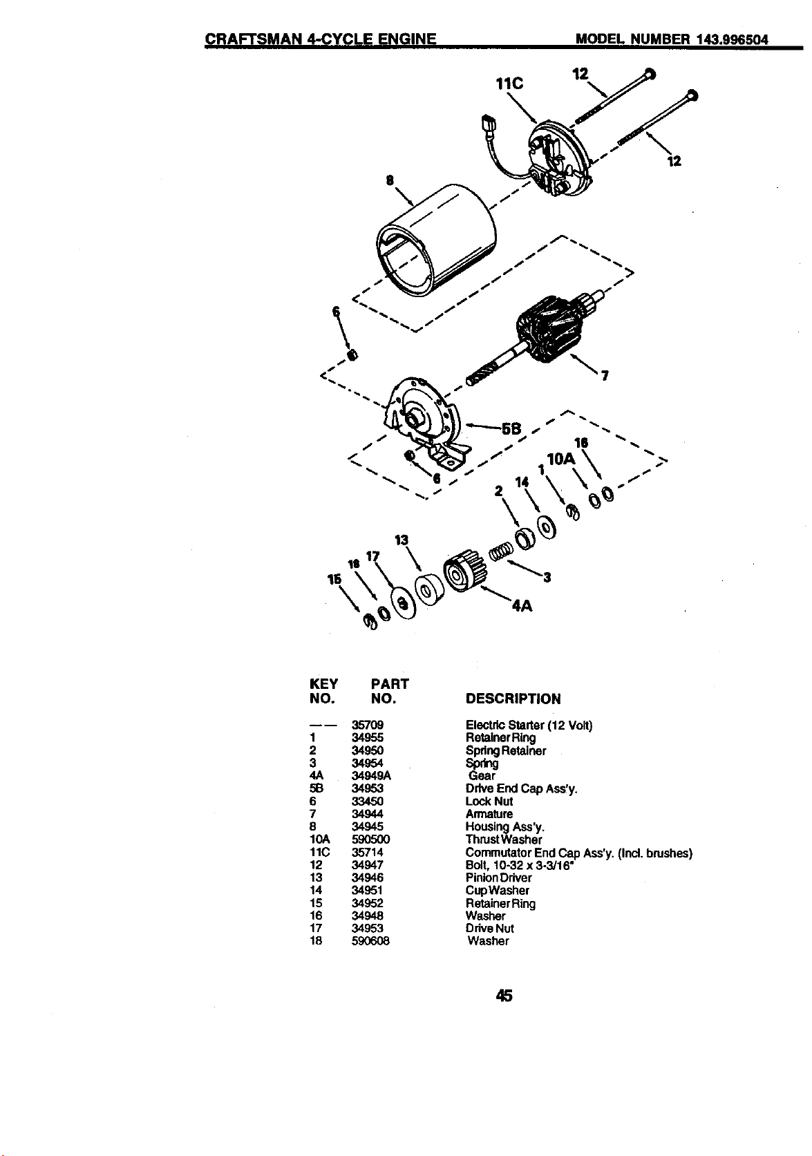
KEY
NO.
mD
1
2
3
4A
513
6
7
8
10A
11C
12
13
14
15
16
17
18
PART
NO.
357O9
34955
3495O
34954
34949A
34953
3345O
34944
34945
59O5OO
35714
34947
34946
34951
34952
34948
34953
59O608
DESCRIPTION
ElectricStarter (12 Volt)
RetainerRing
SpringRetainer
sp_
Gear
Drive End Cap Ass!y.
Lock Nut
Armature
Housing Ass'y.
ThrustWasher
Commutator End Cap Ass'y. (Incl. brushes
Bolt, 10-32 x 3-3'16"
PinionDriver
CupWasher
RetainerRing
Washer
DdveNut
Washer
45
CRAFTSMAN 4-CYCLE ENGINE MODEL NUMBER 143.996504
13
_5
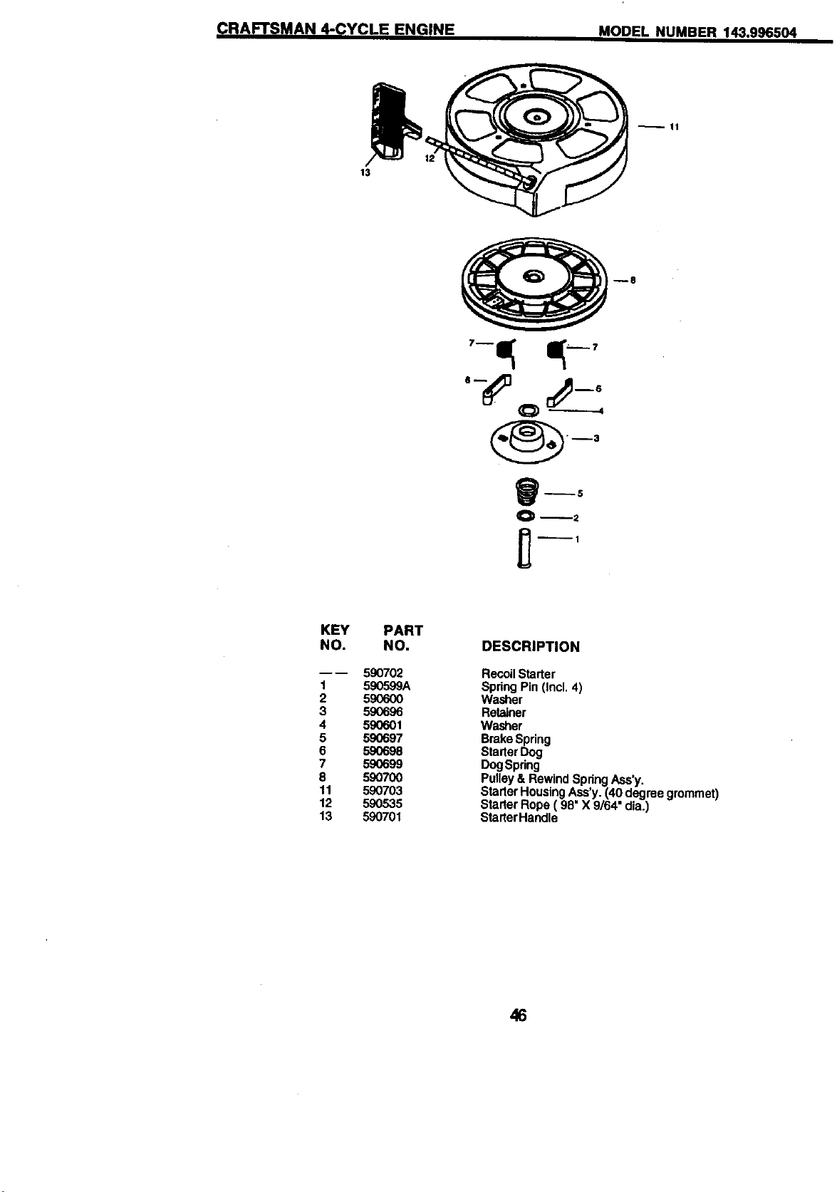
KEY PART
NO. NO.
590702
1 590599A
2 590600
3 590696
4 590601
5 590697
6 59O698
7 590699
8 590700
11 590703
12 590535
13 590701
DESCRIPTION
RecoilStarter
Spring Pin (Incl. 4)
Washer
Retainer
Washer
Brake Spring
Starter Dog
DogSpdng
Pulley& Rewind Spdng Ass'y.
Starter Housing Ass'y.(40 degree grommet)
Starter Rope ( 98" X 9/64" alia.)
StarterHandle
46
CRAFTSMAN 4.-CYCLE ENGINE MODEL NUMBER 143.996504
V--t4
II III m7
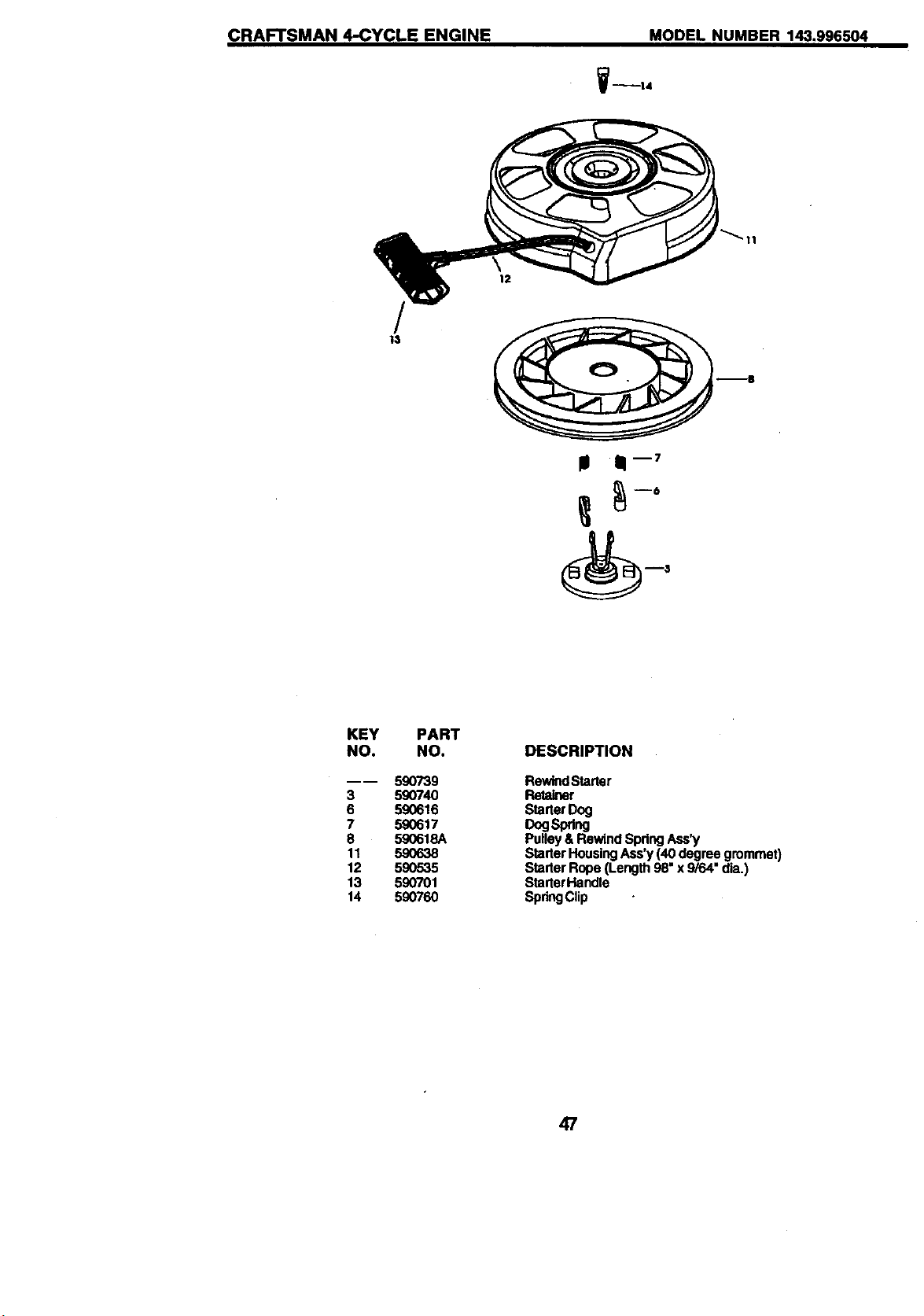
KEY
NO.
3
6
7
8
11
12
13
14
PART
NO.
590739
59074O
590616
590617
590618A
59O638
59O535
590701
59O76O
DESCRIPTION
RewindStartar
Retainer
StarterDog
DogSp_ng
Pulley& RewindSpdng Ass'y
StarterHousingAss'y (40 degree grommet)
Starter Rope (Length 98"x 9/64" dia.)
StarterHandle
SpdngClip
47
For in-home major brand repair service:
Call 24 hoursa day,7 days a week
1-800-4-MY-Home sM(1-800-469-4663)
Para pedir servicio de reparaci6n a domicilio
1-800-676-5811
In Canada for all your service and parts needs call
Au Canada pour tout le service ou les pi_ces
1-800-665-4455
For the repair or replacement parts you need:
Call 6 am-11pm CST, 7 days a week
PartsDirect s.
1-800-366-PART (1-800-366-7278)
Para ordenar piezas con entrega a domicilio
1-800-659-7084
For the location of a Sears Parts and Repair Center
in your area:
Call 24 Hours a day, 7 days a week
1-800-488-1222
For information on purchasing a Sears Maintenance
Agreement or to inquire about an existing Agreement:
Call 9 am-5 pro, Monday - Saturday
1-800-827-6655
SEARS
66938 REV.2 05.27.99 VB Printed in U.S.A.