DEL BER 917.259590
OWNER'S MANUAL
®
=Assembly
, Operation
• Customer Responsibilities
®Service and Adjustments
, Repair Parts
_CAUTION: Read and follow all safety rules and instructions before operating this equipment.
FOR coNSUMER ASS STANCE HOT L NE, CALL THIS TOLL FREE"NUMBER: 1-800-659-5917
................ IliiH.................. i l lllllllfllIHll/l/lllillIll......... .... , • I....
SAFETY RULES
Safe Operation Practices for Ride-On Mowers
IMPORTANT: THIS CUTTING MACHINE IS CAPABLE OF AMPUTATING HANDS AND FEET AND THROWING OBJECTS.
FAILURE TO OBSERVE THE FOLLOWING SAFETY INSTRUCTIONS COULD RESULT iN SERIOUS INJURY OR DEATH,
!. GENERAL OPERATION
• Read, understand, and follow all instructions tn the manual
and on the machine before starting.
• Only allow responsible adults, who are familiar with the
instructions, to operate the machine.
° Clear the area of objects such as rocks, toys, wire, etc,
which could be picked @ and thrown by lhe blade.
• Besure the area is clear of other people before mowing Stop
machine if anyone enters the area..
• Never carry passengers_
o Do not mow in reverse unless absofulely necessary. Always
look down and behind before and while backing.
• Be aware of the mower discharge direction and do not point
it at anyone° Do not operate the mower without either the
entire grass catcher or the guard in place.
• Slow down before turning
• Never leave a running machine unattended. Always turn off
blades, set parking brake, stop engine, and remove keys
before dismounting,
• Turn off blades when not mowing.
• Stop engine before removing grass catcher or unclogging
chute.
• Mow only tn daylight or good artificial light.
• Do not operate the machine while under the influence of
alcohol or drugs.
° Watch for traffic when operating near or crossing roadw_,ys.
• Use extra care when loading or unloading the machine into
a trailer or truck.
tlo SLOPE OPERATION
Slopes are a major factor related to loss-of-control and
tipover accidents, which can resuIt in severe injury or
death. All slopes require extra caution. If you cannot back
up the slope or if you feel uneasy on it, do not mow it..
DO:
,, Mow up and down slopes, not across.
• Remove obstacles such as rocks, tree limbs, etc
• Watch for holes, ruts, or bumps Uneven terrain could
overturn the machine. Taft grass can hide obstacles.
,, Use slow speed. Choose a low gear so that you will not have
to stop or shift while on the slope.
• Follow the manufacturer's recommendations for wheel
weights or counterweights to improve stability.
• Use extra care with grass catchers or other attachments.
These can change the stability of the machine.
• Keep all movement on the slopes slowand gradual, Do not
make sudden changes in speed or direction,
• Avoid starting or stopping on a slope. If tires fose traction,
disengage the blades and proceed slowly straight down the
slope.
DO NOT:
, Donot turnon slopes unless necessary, and then, turn slowly
and gradually downhill, if possible,
° Do not mow near drop*offs, ditches, or embankments. The
mower could suddenly turn over if a wheel is over the edge
of a cliff or ditch, or if an edge caves in.
° Do not mow on wet grass. Reduced traction could cause
sliding,
• Do not try to stabilize the machine by putting your foot on the
groun&
° Do not use grass catcher on steep slopes,
2
i!1, CHILDREN
Tragic accidents can occur if the operator is not alert to the
presence of children_ Children are often attracted to the
machine and the mowing activity. Never assume that
children will remain where you last saw them°
° Keep children outof the mowing area and under the watchful
care of another responsible adult,
• Be alert and turn machine off if children enter the area.
• Before and when backing, look behind and down for small
children,
° Never carry children. They may fall off and be seriously
injured or tntedere with safe machine operation
• Never allow children to operate lhe machine°
• Use extra care when approaching blind corners, shrubs,
trees, or other objects that may obscure vision..
IV. SERVICE
° Use extra care in handling gasoline and other fuels. They are
flammable and vapors are explosive,
Use only an approved container.,
Never remove gas cap or add fuel with the engine
running.. Allow engine to cool before refueling. Do not
smoke,.
Never refuel the machine indoors.
Never store the machine or fuel container insic]e where
there is an open flame, such as a water heater.
° Never run a machine inside a closed area°
° Keep nuts and bolts, especially blade attachment bolts, tight
and keep equipment in good condIliono
° Never tamper with safety devices. Check their proper
operation regularly.
° Keep machine free of grass, leaves, or other debris build-up.
Clean otl or fuel spillage, Allow machine to cool before
storing.
° Stop and inspect the equipment if you strike an objecL
Repair, if necessary, before restarting.
• Never make adjustments or repairs with the engine running°
• Grass catcher components are subject to wear, damage, and
deterioration, which could expose'moving parts or allow
objects to be thrown. Frequently check components and
replace with manufacturer s recommended parts, when nec-
essary_
° Mower blades are sharp and can cut, Wrap the blade(s) or
wear gtoves, and use extra caution when servicing them,
° Check brake operation frequently Adjust and service as
required.
Look for thissymbol to point out important I
A safety precautions. It means I
CAUTION!!! BECOME ALERTI!I YOUR I
SAFETY IS INVOLVED, i
_ELI[ I IIIIIIIII I III II
,,, ,,,,,,,,,,,,
q
CAUTION; Always disconnect spark plug !
A wire and place wire where It cannot contact
1
spark plug tn order to prevent accidental
starting when setting up, transporting,
adjusting or making repairs.
A WARNING A
The engine exhaust from this product contains
chemicals known to the State of California to
cause cancer, birth defects, or other reproduc-
tive harm.
F
oONGRATULAT|ONS on your pLJrchase of a sears
tractor, tt has been designed, engineered and manufac-
tured to give you the best possible dependability and
pefformance_ . ....
Should you experience any problem you cannot easily
remedy, please contact your nearest Sears Service Cen-
tedDepartment, We have competent, welt-trained tech-
nicians and the proper tools to service or repair this trac-
tor,
Please read and retain this manual. The instructions will
enable you to assemble and maintain your tractor prop-
erly. Always observe the "SAFETY RULES".
MODEL
NUMBER 917o259590
SERIAL
NUMBER
DATEOFPURCHASE
THE MODEL AN DSERIAL NUMBERS WILL BE FOUND
ON A PLATE UNDER THE SEAT.
YOU SHOULD RECORD BOTH SERIAL NUMBERAND
DATE OF PURCHASE AND KEEP IN A SAFE PLACE
FOR FUTURE REFERENCE.
MAINTENANCE AGREEMENT
A Sears maintenance agreement is available on this prod-
uct Contact your nearest Sears store for details°
CUSTOMER RESPONSIBILITIES
o Read and observe the safety rules.
° Fo!iow a regular schedule in maintaining, caring for and
using your tractor.
• Follow the instructions under "Customer ResponsibilF
ties" and "Storage" sections of this owner's manual.
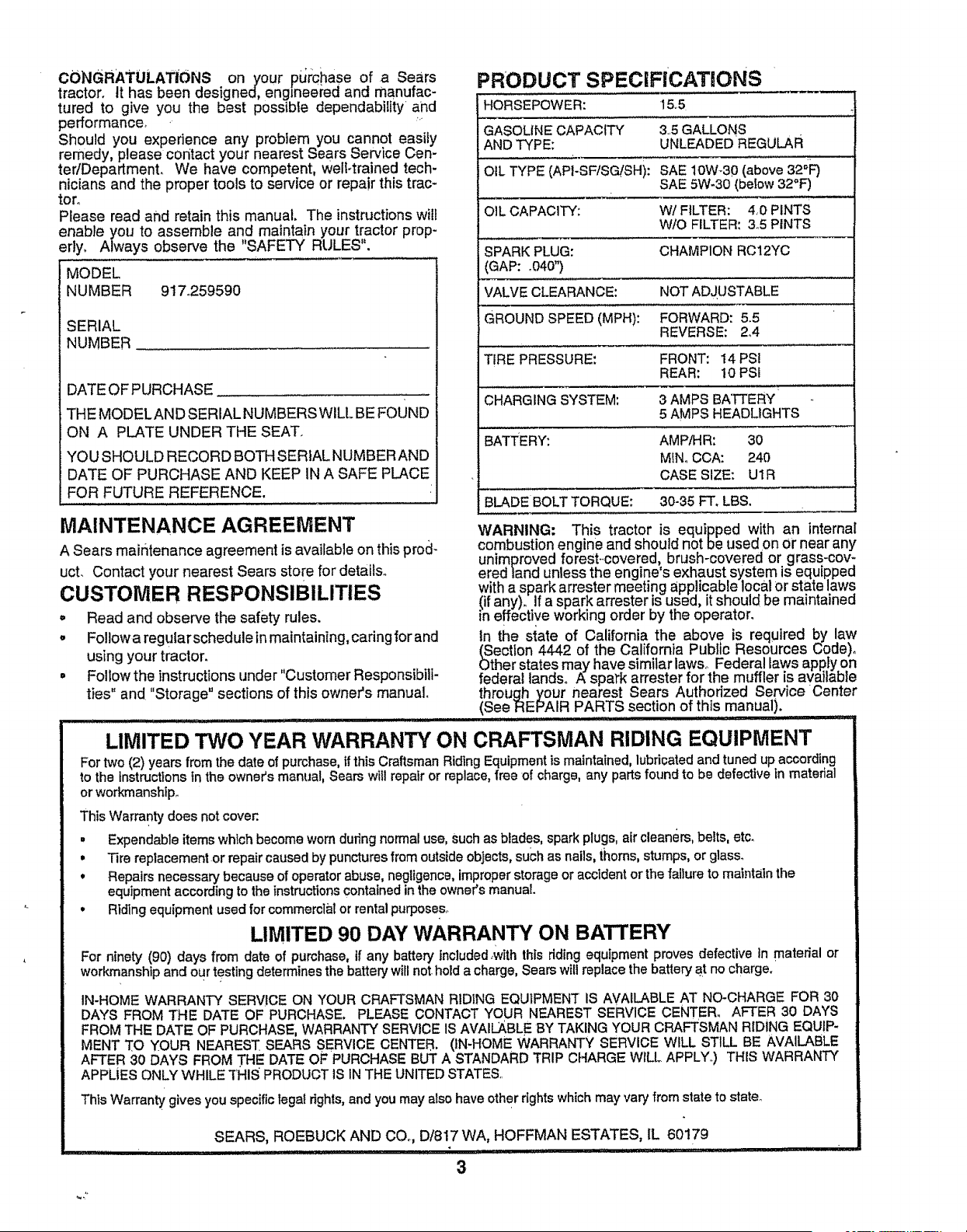
PRODUCT SPECIFICATaONS
HORSEPOWER: 15,5
GASOLINE CAPACITY 35 GALLONS
AND TYPE: UNLEADED REGULAR
OIL TYPE (API-SF/SC._SH): SAE 10W-30 (above 32"F)
SAE 5W-30 (below 32°F)
OIL CAPACITY: W/FILTER: 40 PINTS
W/O FILTER: 35 PINTS
SPARK PLUG: CHAMPION RC12YC
(GAP: °040")
VALVE CLEARANCE: NOT ADJUSTABLE
GROUND SPEED (MPH): FORWARD: 5.5
REVERSE: 2,,4
TIRE PRESSURE: FRONT: 14 PSI
REAR: 10 PSi
CHARGING SYSTEM: 3 AMPS BATTERY
5 AMPS HEADLIGHTS
3ATTERY: AMPfrlR: 30
MINe CCA: 240
CASE SIZE: UlR
BLADE BOLT TORQUE: 30-35 FT. LBS.
WARNING: This tractor is equipped with an internal
combustion engine and should not be used on or near any
unimproved forest-covered, brush-covered or grass-cov-
ered land unless the engine's exhaust system is equipped
with a spark arrester meeting applicable local or state laws
(if any). If a spark an'ester is used, it should be maintained
in effective working order by the operator.
In the state of California the above is required by law
(Section 4442 of the California Public Resources Code)°
Other states may have similar lawso Federal laws apply on
federal lands. A spark arrester for the muffler is available
through your nearest Sears Authorized Service Center
(See REPA,,!RPARTS section of this manual). '............
LIMITED "I3NO YEAR WARRANTY ON CRAFTSMAN RIDING EQUIPMENT
For two (2) years from the date of purchase, tf this Craftsman Riding Equipment is maintained, lubricatedand tuned up according
to the tnstructtons in the owner's manual, Sears will repair or replace, free of charge, any parts found to be defective in material
or workmanship°
This Warranty does not cover.
, Expendable items which become worn during normal use, Such as blades, spark plugs, air cleaners, belts, etc.
° Tire replacement or repair caused by punctures from outside objects, such as nails, thorns, stumps, or glass_
, Repairs necessary because of operator abuse, negligence, improper storage or accident or the failure to maintain the
equipment according to the instructions contained in the owner's manual.
, Riding equipment used for commercial or rental purposes°
LIMITED 90 DAY WARRANTY ON BATTERY
For ninety (90) days from date of purchase, if any batter/Included_with this ddlng equipment proves defective In material or
workmanship and our testing determines the battery will not hold a charge, Sears will replace the battery at no charge.
IN-HOME WARRANTY SERVICE ON YOUR CRAFTSMAN RIDING EQUIPMENT IS AVAILABLE AT NO-CHARGE FOR 30
DAYS FROM THE DATE OF PURCHASE. PLEASE CONTACT YOUR NEAREST SERVICE CENTER. AFTER 30 DAYS
FROM THE DATE OF PURCHASE, WARRANTY SERVICE IS AVAILABLE BY TAKING YOUR CRAFTSMAN RIDING EQUIP-
MENT TO YOUR NEAREST SEARS SERVICE CENTER. (IN-HOME WARRANTY SERVICE WILL STILL BE AVAILABLE
AFTER 30 DAYS FROM THE DATE OF PURCHASE BUT A STANDARD TRIP CHARGE WILL APPLY.) THIS WARRANTY
APPLIES ONLY WHILE "[HIS PRODUCT 1S1NTHE UNITED STATES.
This Warranty gives you specific legal rights, and you may also have other rights which may vary from state to state°
SEARS, ROEBUCK AND COo, D/817WA, HOFFMAN ESTATES, IL 60179
3
SAFETY RULES .....;......... ............................................. 2
PRODUCT SPECIFICATIONS ......;...................... ,;....... 3
CUSTOMER RESPONSIBILITIES ..;.................. 3, 16-19
WARRANTY ..................................................................3
TRACTOR ACCESSORIES ..........................................5
ASSEMBLY ...............•..............................................7-10
OPERATION.. .........................................................11-1B
MAINTENANCE SCHEDULE ...... ........... ............ ,.; ..... 17
SERVICE AND ADJUSTMENTS.". ........... ........ .,21-27
STORAGE ........................................... ;................... ,.. 28
TROUBLESHOOTING ...._........................................ 29-30
REPAIR PARTS - TRACTOR .................... _............ 32-49
REPAIR PARTS - ENGINE .......................... ,......... 50-55
PARTS ORDERING/SERVICE ................ BACK COVER
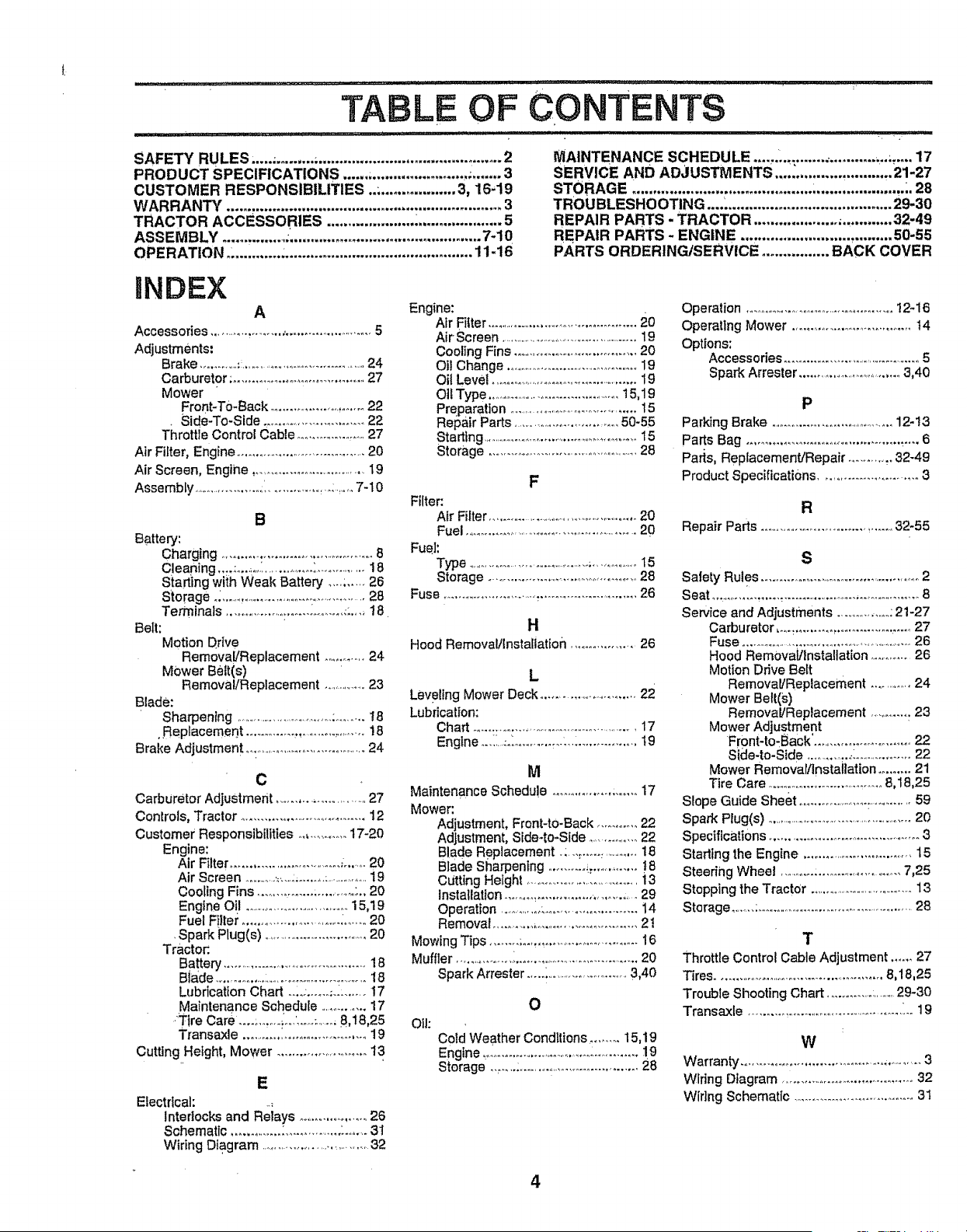
INDEX
A
Accessories .................... _......................... 5
Adjustments:
Brake .............: .......................................24
Carburetor; ..................................... 27
Mower "
Front-To-Back ........................... 22
. Side-To-Side ............................ 22
Throttle Control Cable .....................27
Air Filter, Engine .................................... 20
Air Screen, Engine ..................................19
Assembly .......................i ..................: ........7-10
B
Battery:
Charging .......................................... 8
Cleaning .....:........'..................'o.............. 18
Sta_ing with Weak Battery .... ;..... 26
Storage o_...............................:............... 28
Terminals ..................:................ _:.... 18
Belt:
Motion Drive
Remova!/Replacement ............ 24
Mower Belt(s)
Removal/Replacement ...................23
Blade:
Sharpening .................................:.........18
•Replacement ............. ,........................18
Brake Adjustment o.:..................................24
C
Carburetor Adjustment .............................27
Controls, Tractor ......................................12
Customer Responsibilities ...............17-20
Engine:
Air Filter ............................... ;........20
Air Screen ............,.....:.........;...................19
Cooling Fins ..................................;., 20
Engine Oil .................................15,19
Fuel F!lter........................... :.......20
•Spark Plug(s) ...............................20
Tractor.
Battery ..........................................18
Blade ................:.................................18
Lubrication Chad .... ;......;......... 17
Maintenance Schedule ...............17
.'Tire Care .... ;.......i.,J..o-;........8,t8,25
Transaxle .................................. 19
Cutting Height, Mower ...........................13
E
Electricah
Interlocks and Relays ........................26
Schematic ...............:................_........3t
WiringDiagram ...................................32
Engine:
AirFitter.............................................20
Air-Screen ................................................19
Cooling Fins ......................................20
Ot! Change ..................................... 19
Oil Level ..............................................19
OIt Type ........................................15,19
Preparation ........................................15
RelSairPads ............................50-55
Starting....................................................15
Storage ..............................................28
F
Filter:
Air Filter...................................................20
Fuel ....................................................20
Fuel:
Type ..............................................;...............15
Storage ........................................28
Fuse ............................_............................ 26
H
Hood Removaltlnsta[iatton ...................26
L
Leveling Mower Deck .............................22
Lubrication:
Chart................................................17
Engine _.._i.._._..................................19
M
Maintenance Schedule ........................17
Mower:
Adjustment, Front-to-Back ........... 22
Adjustment, Side-to-Side ...............22
Blade Replacement .:...:..................18
Blade Sharpening .......... ::................!8
Cutting Height ..................................13
Installation ........ ,..............................29
Operation ................_......................... 14
Removal ..........................................21
Mowing Tips ........ ;...................................16
Muffler ..........................................................20
Spark Attester .....,..........................3,40
Oil:
O
Cotd Weather Conditions ......... 15,19
Engine .................................................1.9
Storage 28
Operation ..............................................12-16
Operating Mower .................................. t4
Options:
Accessories .............................................5
Spark Arrester ..................................3,40
P
Parking Brake .....................................12-13
Parts Bag ........................................._....6
Parts, Replacement/Repair ............32-49
Product Specifications ........................... 3
R
Repair Parts .................................... 32-55
S
Safety Rules .................................................2
Seat ............................................................8
Service and Adjustments ...................,21-27
Carburetor ,oo._................................27
Fuse .........................................................26
Hood Rem0val/Installation ............26
Motion Drive Belt
Removal/Replacement ..............24
Mower Belt(s)
Removal/Replacement .............23
Mower Adjustment
Front-to-Back'. .......................... 22
Sicle-to-Side ..............:.................22
Mower Removal/installation ......... 21
Tire Care ................................. 8,18,25
Slope Guide sheet ......................r............ 59
Spark Plug(s) ...................................................20
Specifications ...............................................3
Stadtng the Engine ................................ 15
Steering Wheel ....................................7,25
Stopping the TractOr .....................................13
Storage ...... :...............................................28
T
Throttle Control Cable Adjustment .......27
Tires ...................................................8,18,25
Troubte Shooting Chart ..............:...........29-30
Transaxle ....................................................19
W
Warrant',,/....................................................3
Wiring Dtagram ..........................................32
Wiring Schematic ................................. 31
4
,i.,lll_,. _ _ • .= _............... i i..lll,i .i..ii.i
ACCESSORIES AND ATTACHMENTS
These accessories and attachments were available through most Sears retailoutlets and service centers when the tractor was purchased.
Most .Sears stores can order these items for you when you provide the model number of your tractor; ' '
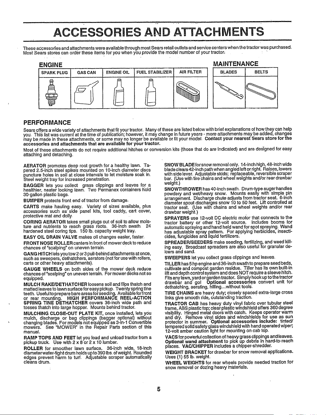
ENGINE MAINTENANCE
SPARK PLUG GAS CAN ENGINE O_L FUEL STABILIZER AIR FILTER BLADES BELTS
PERFORMANCE
Sears offersa wide variety of attachments that fit your tractor. Many of these are listed below with brief explanations of how they can help
you. This list was current at the time of publication; however, it may change infutut;e years - more attachments may be added, changes
may be made in these attachments, or some may no longer be available or f{tyour model, Contact your nearest Sears store for the
accessories and attachments that are available for your tractor.
Most of these attachments do not require additional hitches or conversion kits (those that do are[ndicated) and are designed for easy
attaching and detaching..
AERATOR promotes deep root growth for a healthy lawn, Ta-
pered 2,5-inch steel spikes mounted on lO-inch diameter discs
puncture holes in soil at close intervals to let moisture soak in,,
Steel weight tray for increased penetrat One
BAGGER lets you collect grass clippings and leaves for a
healthier, heater looking lawn. Two Permanex containers l_old
30-gallon plastic bags.
BUMPER protects front end of tractor from damage,
CARTS make hauling easy,, Variety of sizes available, plus
accessories such as* side panel kits, tool caddy, cart cover,
protective mat and dolly.
CORING AERATOR takes small plugs out of soil to allow mois-
ture and nutrients to reach grass roots, 36-inch swath 24
hardened steel coring tips. 150 tbocapacity weight tray.
EASY OIL DRAIN VALVE makes oil changes easier, faster.
FRONT NOSE ROL.LER canters in frontof mower deckto reduce
chances of "s¢al ping" on uneven terrain.
GANG HITCH lets you tow 2 or 3 pulFbehind attachments at once,
such as sweepers, dethatchers, aerators (not for use with rollers,
carts or other heavy attachments),
GAUGE WHEELS on both sides• of the mowe=; deck reduce
chances of "scalptng"o,n uneven terrain, Formowerd_cksnotso
equipped.
MULCH RAKFJDETHATCHER loosens sol} and flips thatch and
matted leaves to lawn surface for easy ptckup_ Twenty spring tIne
teeth, Useful toprepare bare areas forseeding. Available forfront
or rear mounting. HIGH PERFORMANCE REEL.ACTION
SPRING TINE DETHATOHER covers 36-inch wide path and
tosses thatch into large hopper. Mounts behind tractor_
MULCHING CLOSE-OUT PLATE KIT, once Installed, lets you
mutch, discharge or bag clippings (bagger optional) without
changing blades, For models not equipped as 3-in-1 Convertible
mowers. See "MOWER" in the Repair Parts section of this
manual.
RAMP TOPS AND FEET let you load and unload tractor from a
pickup track. 0so with 2 x 8 or 2 x 10 lumber.
ROLLER for Smoother lawn surface. 36-idch wide, 18-inch
diameterwater-tight drum holds upto 390 Ibs, Ofweight,, Rounded
edges prevent harm to tuff, Adjustable scraper automat{tally
cleans drum.
SNOW BLADE forsnow removal only. 14-inch high, 48-1nbhwide
blade clears 42-Inch path when angred left or righL Raises, lowers
with side lever. Adjustable skids; replaceable, reversible scraper
bar. (Use with tire chainsand wheel weights and/or i'ear drawbar
weight°)
SNOWTHROWER has 40-inch swath_ Drum-type auger bandies
powdery and wet]heavy snow. Mounts easily with simple pin
arrangemenL Discharge chute adjusts from tractor seat. 6-_nch
diameter spout discharges snow 10 to 50 feet. Lift controlled at
tractor seat. (Use with chains and wheel weights and/or rear
drawbar weight,)
SPRAYERS use 12-volt DO electric motor that connects to the
tractor battery or other 12-volt source, includes booms for
automatic spraying andhand held wand for spot spraying° Wand
has adjustable spray pattern, For applying herbicides, insecti-
cides, fungicides and liquld fertilizers.
SPREADER/SEEDERS make seeding, fertilizing, and weed kill-
ing easy. Broadcast spreaders are also useful for granular de-
icers and sand_
SWEEPERS let you collect grass clippings and leaves°
TILLER has 5 hp engine and 36-inch swath to prepare seed beds,
cultivate and compost garden residue° T_llerhas its own btdlt-tn
liftand depth control system and does NOT require a sleeve hitch.
Fits any lawn, yard or garden tractor. Simply hook up to the tractor
drawbar and gel Optional accessories convert unit for
dethatching, aerating, hUllng._wlthout tools:
TIRE CHAINS are heavy duty; closely spaced extra-large cross
links g ve smooth dde_ outstanding traction.
TRACTOR CAB has heavy duty vinyl fabric over tubular steel
frame, ABS plastic top; clear plastic windshield offers 360 degree
visibility, Hinged metal doors with catch, Keeps operator warm
anddry. Remove vinyl Sides ahd windshields for use as sun
protector in summer, Optional accessories include: tinted/
tempered solid safety glasswindshleld with hand operated wiper;,
12-volt amber caution Ilght for m0unting on cab top_
VACS for powerful collection of heavy grass clippings and leaves.
Optional wand attachment to pick up debns tnhard-t_,reach
places. VACICHIPPER includes a chipper-shredder.
WEIGHT BRACKET for drawbar for snow remova_applications,
Uses (1) 55 iboweight,,
WHEEL WEIGHTS for rear wheels provide needed traction for
snow remova! or dozing heavy materials,
5

CONTENTS OF ARDWARE PAC
Parts Bag Contents SlloWn full size
(1) Shoulder Bolt
5/16-18
(t) Knob
(I).Washer
17!32 x 1-3/16 x 12 Ga.
_r
(2)Screws
#! 0 x 5/8
(2) Lock
Washers
#1o
,2 We'dNut i lo Q6G
_ . (2: washers 3/i6x /4x _ uge
(2) Hex Bolts 1/4-20 x 3/4
(2) Hex Nuts 1/4..20
(2) Washers _/_.(_ (2) Lock
9/32 X5/8 _ Washel;s 1/4
16 Ga,
, Pa_s packed separately in carton
,, , ,,,,,,,,,,,,,,,,,,,,
Steerir_g
Wheel
,_ , jill ;_]-
. Manual
,,, ,,, ..............,,
Seat
Mulcher Cassette
Plate
Parts Bag
:: ...... "..................... 1,, i , i , ii
Parts, bag, contents not shown full size
i i l,,iH,i i;: ...................... ...........
(2) Center- @
(2) Shoulder lock Nuts
BOlts (2) Gauge
Wheels
2i Washers 3t8
x 7/8 x 14 Gauge
Steering
Wheel
Insert
(2) Keys
Steering
Sleeve
S!ope Sheet . !
ASSEMBLY
Your new tractor has been assembled at the factory wi{h exception of {hose pai-tsleft unassembled |o_:Shipping purposes°
To ensure safe and proper operation of your tractor, all parts and hardware yoLi assemble must be tightened securely. Use
the correct tools as necessarY to insure proper tightness°
TOOLS REQUIRED FOR ASSEMBLY
A socket, wrench set will make assembly easier. Standard
wrench sizes are listed.
(2) 7/16" wrench
Utility knife
Tire pressure gauge
(!) 1/2" wrench
(1) 9/16" wrench
(1) 3/4" socket w/drive ratchet
Phillips screwdriver
When right and left hand is mentioned in this manual, it
means when you are in the operating position (seated
behind the steering wheel).
TO REMOVE TRACTOR FROM CARTON
UNPACK CARTON
= Remove all accessible loose parts and parts cartons
from carton (See page 6)°
o Cut, from top to bottom, along lines on all four corners
of carton, and lay panets flato
. Remove mower and packing materials.
o Check for any additional loose parts or cartons and
remove°
BEFORE ROLLING TRACTOR OFF SKID
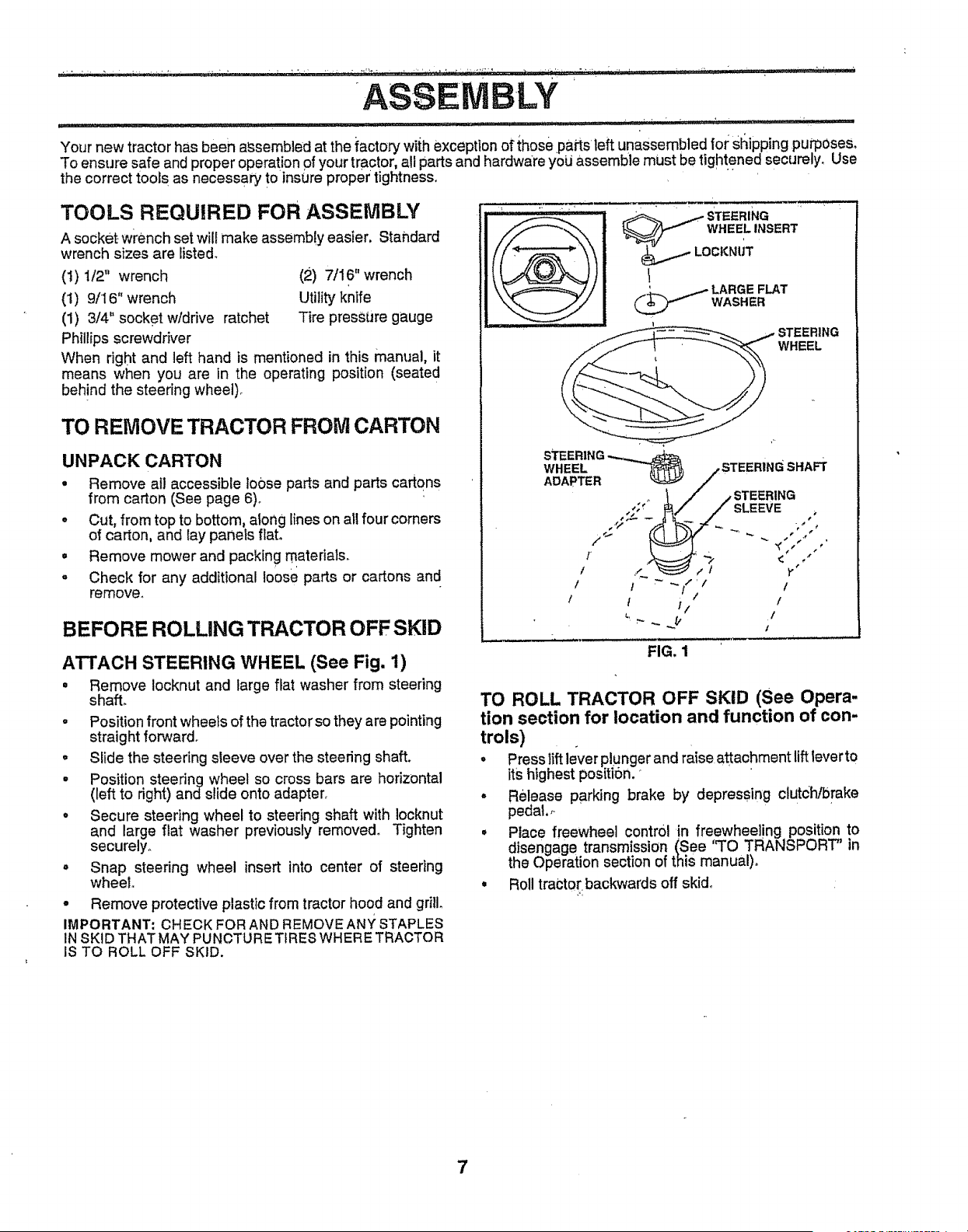
ATTACH STEERING WHEEL (See Fig. 1)
• Remove !ocknut and large flat washer from steering
shall
- Position front wheels of the tractor so they are pointing
straight forward.
° Slide the steering sleeve over the steering shaft.
° Position steering wheel so cross bars are horizontal
(left to right) andslide onto adapter.
• Secure steering wheel to steering shaft with Iocknut
and large flat washer previously removed. Tighten
securely.
• Snap steering wheel insert into center of steering
wheel.
° Remove protective plastic from tractor hood and gri&
IMPORTANT; CHECK FOR AND REMOVEANY STAPLES
INSKID THAT MAY PUNCTURE TIRES WHERE TRACTOR
IS TO ROLL OFF SKID,
. STEERING '
WHEEL INSERT
_ ARGE FLAT
WASHER
I t _ _!/// t
! t i/ /
L ...,....._ 1/
FIG. 1
TO ROLL TRACTOR OFF SKID (See Opera-
tion section for location and function of con-
trols)
o Press lift lever plunger and raise attachment lift lever to
its highest position.
° Release parking brake by depressing clutc]'Vbrake
pedal.
o Place freewheel control in freewheeling position to
disengage transmission (See "TO TRANSPORT" in
the Operation section of this manual)°
• Roll tractor:backwards off skid_
7
_;_i:;:_._:_;]:._.._;,._'.',_,-_L, _ i_ _i _: _,,i_._i _;; ;__:_ 7:_7_,+"..... _ '_...... ,..._,_i,, i ,, . • it . .. ? •
ASSEMBiLY
, _ b _ • j _ i,., , ,. ,t,., ,r,,,,,_!,,_'. %:,i . 17 _: , ' ...................... . , :_ :_ <, , . , _ • : .: _ . .... _ . .......... , ....
H_O_O ,SETUP YOUR TRA_T.OR..._ ...-.!NSTAL.L_SIEAT_.(S.e.eFig_.3) .,.
C!_t"t,_l_E_'r'_";".........BA_ERY' _.......(See"""Fig."_i ' ": :_ : < ', _ : ' Adiust _tbefd_e tighi_P;_n'gj_,.dj_ustmentkMOb,
0÷
PoSitive t_tfftinai must be_€onnebibd o
first to prevent sparklng fr.olm_¢c_en- ,,i;
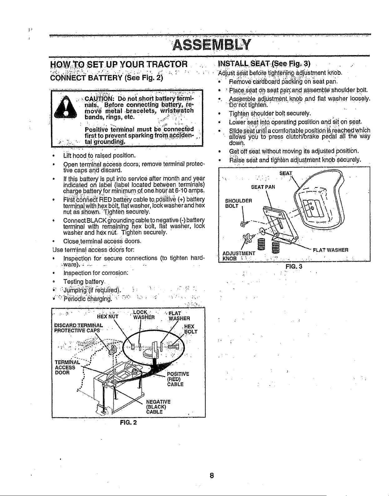
. Lifthood {0 rai_ed position,
• Open terml"nal .access doors; remove termlr_il protec_ °
tire caps aq_ discard,
• If this battery is put into service after month arid year
incline,ted on labei (label located be_en termirta_ls)
charge batterY for rain mum _f.oneh0Ut.a.t 6-10 amp&
o First:t:onne¢[ RED batte_ cable to, poslt!.ve (+) battery
terminal:with hex bolt, flaiwasher, lock washer and hex
nut as'.sh6_,6, :Tighten Securely;
• Connect BLACK gi:oundincjcable to negative (-).battery
terminal wffh remaining Sex b01t, flat washer, lock
washer and hex net',. Tighten securely. " "
° Closeterminaf aCceSs doors. "
Use terminal access d6ors for:
° !nspectlo.n for secure connections (to tighten hard°
• inspection for corrosion;
o Testing battery,.
, -,,LOCt£;: '., -',,_LAT
W_SHER - ,WASHER
ACCESS
DOO_ - _QSmvE
•; (RED)
: CABLE
NEGATIVE
(BLACK)
CABLE
FIG, 2
.'.p!_e;._eat Oh.Se_t #_n;an# as"semb!_ _shoulder bolt,
..Ass_m.ble.a,djOst.m..,ent,k_._b ,and. ftat washer loosely,
"_'nq[ righted.' • ' " ' ' ..... ' ' '
.Tighp.n,shoulder boi.t securely, ....
L0_er:s.eSii_to. operating position and Slitor_#_a,t,
Stide._eat'u_iiia comfoPtablepositiOri i_ ie_,checl_hich
_i!dwS"Y_Ot6"press _JlOtch_r_.ke-pedal _i!i_{fie W_iy
aowh, " " " ' '
,idff dear Without moving ffs adju,sted position,
is_ Seo.tand tigRt_n_;dj:ustr_entl_nob"securely,
SEAT PAN
SHOULDER
FLAT WASHER
ADJUSTMENT
RG.3
_ , . ,
!; .,,,
8
i,, i,, i iii ,111i1, i,,11111,,11_ r,
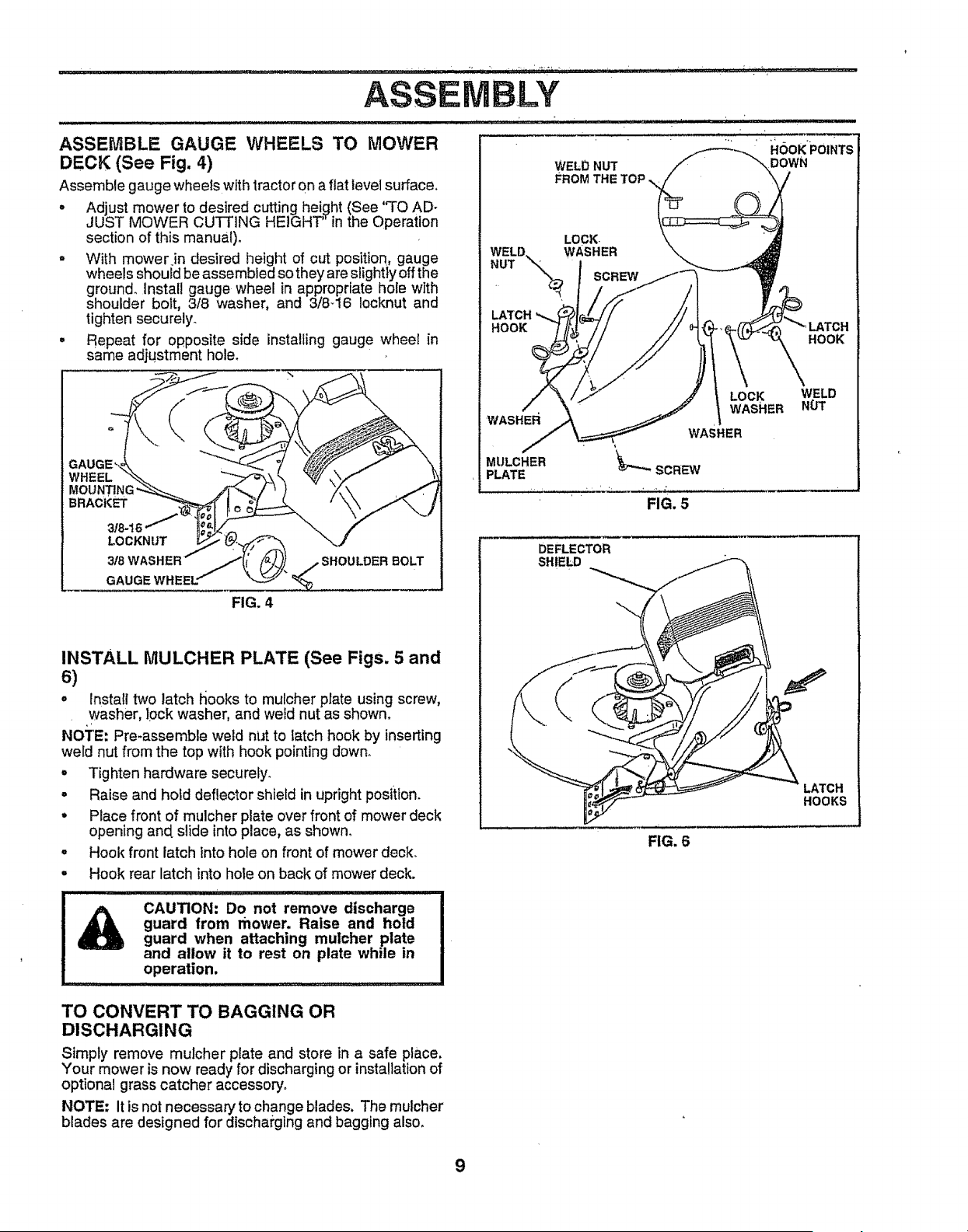
ASSEMBLE GAUGE WHEELS TO MOWER
DECK (See Fig. 4)
Assemble gauge wheels with tractoron a fiat level surface.
, Adjust mower to desired cutting height (See 'q_OAD-
JUST MOWER CUTTING HEIGHT" in the Operation
section of this manual).
- With mower in desired height of cut position, gauge
wheels should beassembled so they are slightly eft the
ground. Install gauge wheel in appropriate hole with
shoulder bolt, 3/8 washer, and 3/8-16 Iocknut and
tighten securely.
• Repeat for opposite side installing gauge wheel in
same adjustment hole_
WHEEL
BRACKET
LOCKNUT
WELD NUT
FROM THE TOP
LOCK
WELD. WASHER
FIG. 4
INSTALL MULCHER PLATE (See Figs. 5 and
S)
° lnsta!l two latch hooks to mulcher plate using screw,
washer, lock washer, and weld nut as shown.
NOTE: Pre_assemble weld nut to latch hook by inserting
weld nut from the top with hook pointing down.
• Tighten hardware securely_
• Raise and hold deflector shield in upright position.
° Place front of mulcher plate over front of mower deck
opening and slide into place, as shown.
° Hook front latch into hole on front of mower deck.
• Hook rear latch into hole on back of mower deck.
I I III I I I I['['1 ill!l; : T::T ::
CAUTION: Do not remove discharge I
guard from mower. Raise and hold I
guard when attaching mulcher plate !
and allow it to rest on plate while in J
operation. J
LATCH
HOOK
.... HOOK POINTS
DOWN
WASHER
MULCHER
PLATE
DEFLECTOR
SHIELD
HOOK
LOCK
WASHER
WASHER
_"_" SCREW
FIG. 5
WELD
H0T
LATCH
HOOKS
FIG. 6
TO CONVERT TO BAGGING OR
DISCHARGING
Simply remove mulcher plate and store in a safe place.
Your mower is now ready for discharging or installationof
optional grass catcher accessop/.
NOTE: It is not necessary to change blades. The mulcher
blades are designed for discharging and bagging also,
9
ASS
CHECK TIRE PRESSURE
The tiresonyour tractor were overinflated atthe factory for
shipping purposes_ Correct tire pressure iS important for
best cutting performance,.
= Reduce tire pressure to PSI shown in =PRODUCT
SPECIFICATIONS" on page 3 of this manual°
J, ,.... , ,,,,,, ,,,,. ,,,, ,,,,_._,,,,,,,,,,, , i i i
,/'CHECKLIST
BEFORE YOU OPERATE AND ENJOY YOUR NEW
TRACTOR, WE WISH TO ASSURE THAT YOU RECEIVE
THE BEST PERFORMANCE AND SATISFA CTION FROM
THIS QUALITY PRODUCT.
PLEASE REVIEW THE FOLLOWING CHECKLIST:
CHECK DECK LEVELNESS
For best cutting results, mower housing should be properly
leveledo See "TO LEVEL MOWER HOUSING" in the
Service and Adjustments section of this m_nuaL
CHECK FOR PROPER POSITION OF ALL
BELTS
See the figuresthat are shown for replacing motion and
mower blade drive belts in the Service and Adjustments
section of this manual Verify that the belts are routed
correctly:
CHECK BRAKE SYSTEM
After you 1earnhow to o"perate your tractor, check to see
that the brake is properly adjusted° See "TO ADJUST
BRAKE" in the Service and Adjustments section of this
v' All a.ssembly instructions have been completed.
,/ No remaining loose parts in carton,.
,/" Battery !s properly prepared and charged, (Minimum
I hour at 6 amps),.
#" Seat is adjusted comfortably and tightened securely,
,/ All tires are properly inflated, (For shipping purposes,
the tires were overinflated at the factory).
v" Be sure mower deck is properly 1eveled side-to-side/
front-toorear for best cutting results. (Tires must be
properly inflated for leveling).
v" Chec1_mower acid drive belts. Be sure they are routed
properly around pulleys and inside all belt keepers.
v" Checkwiring See that all connections are still secure
and wires are properly clamped.
v" Before driving tractor, be sure freewheel control is in
drive position.
manual.
WHILE LEARNING HOW TO USE "(OUR TRACTOR, PAY
EXTRA ATTEIVTION TO THE FOLLOWING IMPORTANT
ITEMS:
,/ Engine oil is at proper level.
,/ Fuel tank is filled with fresh, clean, regular unleaded
gasoline_
,/ Become familiar with all controls - their location and
function. Operate them before you start the engine.
,/ Be sure brake system is in safe operating condition_
v" It is important to purge the transmission before you
operate your new tractor for the first time. Follow
roper starting and transmission purging Instructions
See q'O START ENGINE and PLIRGETRANSMtS-
SION" in Operation section of this manual)_
10
OPERATION
'/_1, ,iqlll it, i i I' , _ ........... _ ....................... ,,, i'111
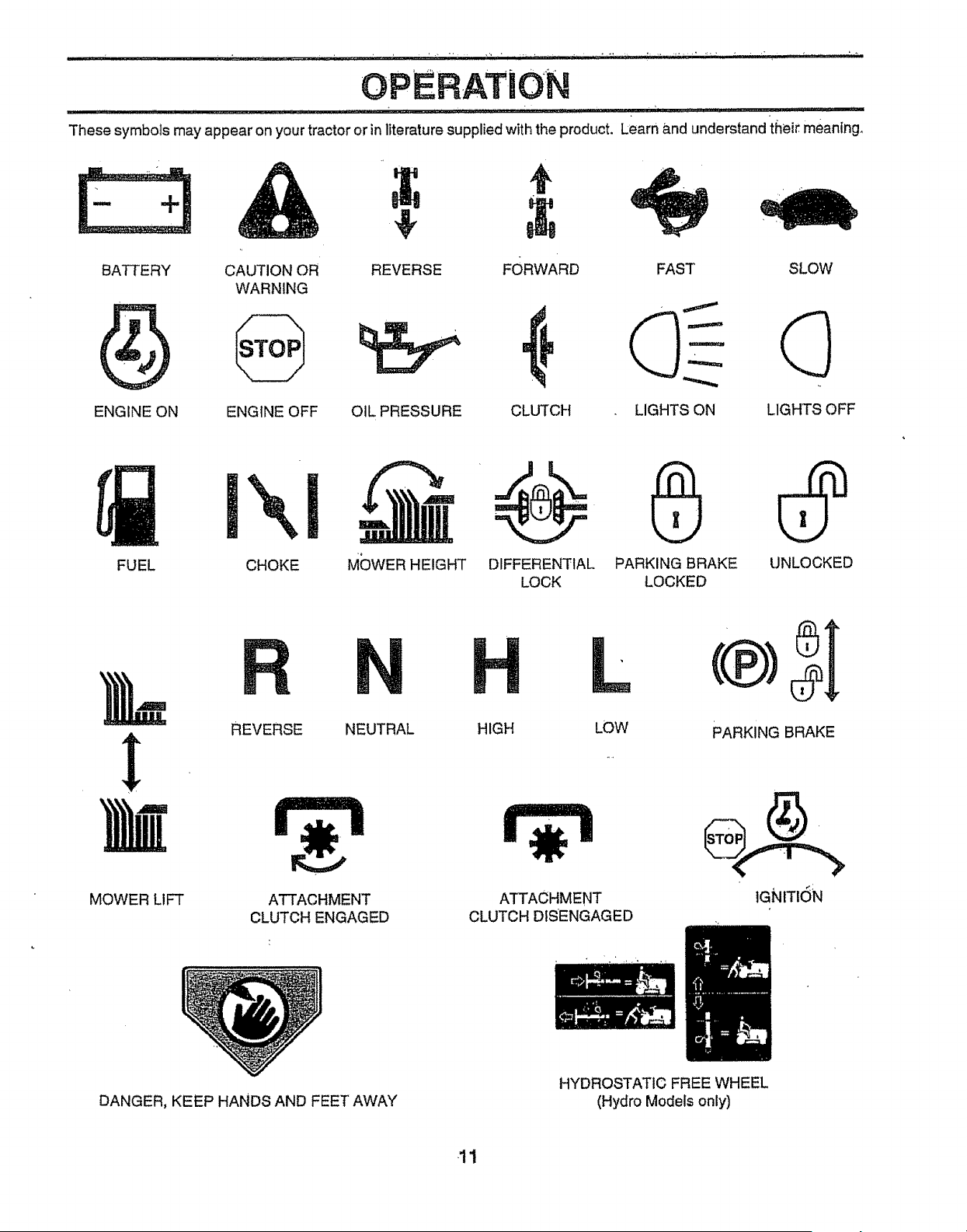
These symbols may appear on your tractor or in literature supplied with the product, Learn and understand iSeir meaning°
BATTERY CAUTION OR REVERSE FORWARD FAST SLOW
WARNING
ENGINE ON ENGINE OFF OIL PRESSURE CLUTCH LIGHTS ON LIGHTS OFF
FUEL
CHOKE M(DWER HEIGHT DIFFERENTIAL PARKING BRAKE UNLOCKED
LOCK LOCKED
MOWER LIFT
REVERSE NEUTRAL HIGH
r=l
ATTACHMENT
CLUTCH ENGAGED
LOW PARKING BRAKE
ATTACHMENT
CLUTCH DISENGAGED
IGNITION
DANGER, KEEP HANDS AND FEET AWAY
HYDROSTATIC FREE WHEEL
(Hydro Models only)
11
OPERATION
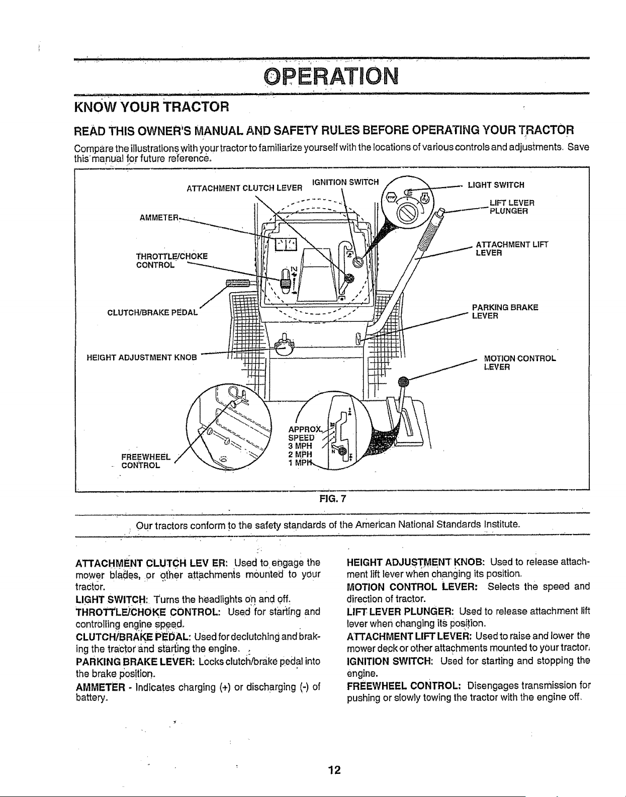
KNOW YOUR TRACTOR
READ THIS OWNER'S MANUAL AND SAFETY RULES BEFORE OPERATING YOUR TRACTOR
Compare the illustrations with your tractorto familiarize yourself with the locations of various controls and adjustments, Save
thismanual ipr future referenceo
ATTACHMENT CLUTCH LEVER
THROTTLE/CHOKE
CONTROL
CLUTCHIBRAF.E PEDAL
IGNITION swITCH LIGHT SWITCH
_. ........ " LIFT LEVER
-'-_ PLUNGER
ATTACHMENT LIFT
LEVER
PARKING BRAKE
LEVER
HEIGHT ADJUSTMENT KNOB
MOTION CONTROL
LEVER
SPEED
3 MPH
FREEWHEEL --_ 2 MPH
CONTROL t
FIG. 7
Our tractors conform to the safety standards of the American Nattonat Standards Institute,
ATTACHMENT CLUTCH LEVER: Used to engage the
mower blades, or other a_pchmenis mbunted to your
tractor,
LIGHT SWITCH: Turns the headlights on and off_
THROTTL_CHOKE CONTROL: Used for start{rig and
controlling engine sp_ed_
CLUTCHIBRAL_ PEDAL: Used fordectutchtng and brak-
ing the tractor'S.hal sta_ng the engine, •:
PARKING BRAKE LEVER: Locks clutch/brake pedal into
the brake position.
AMMETER - Indicates charging (+) or discharging (-) of
battery.
HEIGHT ADJUSTMEN'[ KNOB: Used to release attach-
ment lift lever when 0hanging its position,
IViOTION CONTROL LEVER: Selects the speed and
direction of tractor.
LIFT- LEVER PLUNGER: Used to release attachment lift
lever whet1changing its position,
ATTACHMENT LIFT LEVER: Used to raise and lower the
mower desk or other attachments mounted to your tractor,
IGNITION SWITCH: Used for starting and stopping the
engine.
FREEWHEEL CONTROL: Disengages transmission for
pushing or slowly towing the tractor with the engine off,
_r
12
............................... .,, _ :: i ¸....... _- ,i"'T'T _ , _ _ _.... " .... -.-- .-_/ ,, i i, ii,,,i,,i,,,u I!'" ii, ,i , ,,wl,¸ ,,, ,,i
OPERATIO
.......... ....... . _ ...................:, ....... _ i ,_i_T- <' ' _ ,_,,,_-_
.. _ I__ The operation of any tractor can result in foreign objects thrown into the eyes, which can I
,_ _sE_] result in severe eye damage. Always wear safety glasses or eye shields while operating your |
,_ tractor or perforn_ing any adjustments or repairs. We recommend a wide vision safety mask |
_M,, over the spectacles or standard safety glasses. !
L
HOW TO USE YOUR TRACTOR
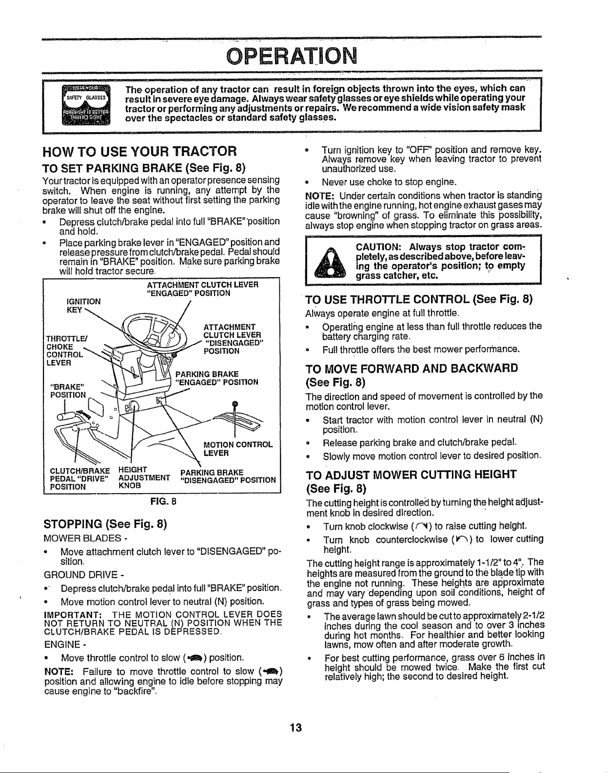
TO SET PARKING BRAKE (See Fig. 8)
Your tractor is equipped with an operatorpresence sensing
switch. When engine is running, any attempt by the
operator to leave the seat without first setting the parking
brake wilt shut off the engine.
= Depress clutch/brake pedal into full "BRAKE"'position
and holdo
,, Place parking brake lever in "ENGAGED" position and
release pressure from clutch/brake pedal. Pedal should
remain n "BRAKE" position. Make sure parking brake
will hold tractor secure.
ATTACHMENT CLUTCH LEVER
"ENGAGED" POSITION
IGNITION
KEY "_.,,.. ATTACHMENT
CLUTCH LEVER
THROTTLE/ "DISENGAGED"
CHOKE POSITION
PARKING BRAKE
"ENGAGED" POSITION
POSITION
CLUTCH/BRAKE HEIGHT
PEDAL "DRIVE" ADJUSTMENT
POSITION KNOB
FIG. 8
MOTION CONTROL
LEVER
PARKING BRAKE
"DISENGAGED" POSITION
STOPPING (See Fig. 8)
MOWER BLADES -
• Move attachment clutch lever to "DISENGAGED" po-
sitiono
GROUND DRIVE -
o Depress clutch/brake pedal into full "BRAKE" position.
° Move motion control lever to neutral (N) position°
IMPORTANT: THE MOTION CONTROL LEVER DOES
NOT RETURN TO NEUTRAL (N) POSITION WHEN THE
CLUTCH/BRAKE PEDAL IS DEPRESSED.
ENGINE -
• Move throttle control to slow (=t_) position.
NOTE: Failure to move throttle control to slow (,,gt)
position and allowing engine to idle before stopping may
cause engine to "backfire'L
. Turn ignition key to "OFF' position and remove key.
Always remove key when leaving tractor to prevent
unauthorized use.
° Never use choke to stop engine.
NOTE; Under certain conditions when tractor is standing
idlewith the engine running, hot engine exhaust gases may
cause "browning" of grass, To efiminate this possibility,
always stop engine when stopping tractor on grass areas.
I _ CAUTION: Always stop tractor com-
pletely, as described above, before leav-
ing the operator's position; to empty
grass catcher, etc. '
.................. I i ii1,1 i iiiiii
TO USE THROTTLE CONTROL (See Fig. 8)
Always operateengineat full throttleo
• Operatir,g engine at less than full throttle reduces the
battery charging rate.
• Full throttle offers the best mower pefforr_ance.
TO MOVE FORWARD AND BACKWARD
(See Fig. 8)
The direction and speed of movement is controlledby the
motion control lever.
° Start tractor with motion control lever in neutral (N)
position,.
• Release parking brake and clutch/brake pedal.
° Slowly move motion control lever to desired position._
TO ADJUST MOWER CUTTING HEIGHT
(See Fig. 8)
The cuttingheight iscontrolledby tLJrningthe height adjust-
ment knob in desiied direction.
° Turn knob clockwise (_) to raise cutting height.
- Turn knob counterclockwise (F'-_)to lower cutting
height,
The cutting height range is approximately 1-1/2" to 4"_ The
heights are measured from the ground to the bla.de'tip with
the engine not running. These heights are approximate
and may vary depending upon soil conditions, height of
grass and types of grass being mowed.
° The average lawn should be cut to approximately 2-1/2
inches during the cool season and to over 3 inches
during hot months. For healthier and better looking
lawns, mow often and after moderate growth_
° For best cutting performance, grass over 6 inches in
height should be mowed twice. Make the first cut
relatively high; the second to desired height°
13
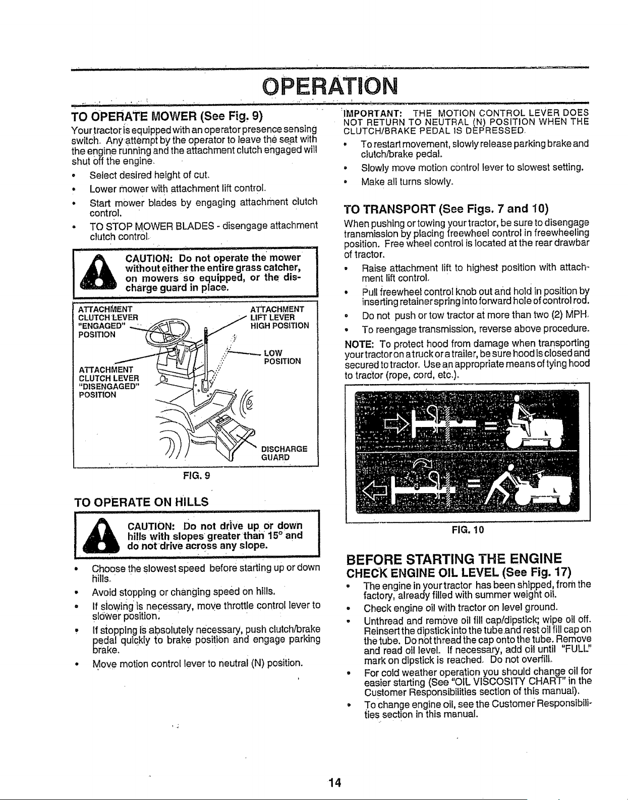
TO OPERATE MOWER (See Fig, 9)
Your tractoris equipped with an operator presence sensing
switch° Any,attempt by the operator to leave the seat with
the engine running and the attachment clutch engaged will
shut off the engine.
• Setect desired height of cut,
• Lower mower with attachment lift control.
= Start mower blades by engaging attachment olutch
control.
= TO sToP MOWER BLADES- disengage attachment
clutch control
CAUTION; Do not operate the mower
wi{hout either the entire grass catcher,
on mowersso equipped, or the dis-
charge guard in place.
ATTACHMENT ATTACHMENT
FIG. 9
TO OPERATE ON HILLS
i & CAUTIO"_ Do not drive uP Or down
hills with slopes greater than 15°and
do not drive across any slope.
-, ,,,,,,,,,,,,,,,,,,,,,,,,,,,,',,,,,,,,,,,,, , , " "" ..... ' , , ,, , , in i i
° Choose the slowest speed before starting up or down
hills,,
• Avoid stopping or changing speed on hills,
• If siowing .isnecessary, moye throttle control lever to
S{ower position,
• if stopping is absolutely necessary, push clutch/brake
pedal qulqk{y t'o brake position and engage parking
brake, ' "
° Move motion control lever to neutral (N) position.
,5
O ERATION
'IMPORTANT: THE MOTION CONTROL LEVER DOES
NOT RETURN TO NEUTRAL (hi) POSITION WHEN THE
CLUTCH/BRAKE PEDAL IS DEPRESSED
° To restart movement, slowly release parking brake and
clutch/brake pedal.
° Slowly move motion control lever to slowest setting.
• Make alt turns slowly°
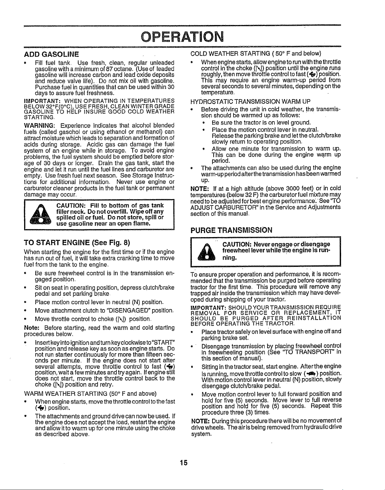
TO TRANSPORT (See Figs. 7 and 10)
When pushing or towing your tractor, be sure to disengage
transmission by placing freewheel control in freewheeling
position. Free wheel controf is located at the rear drawbar
of tractor.
• Raise attachment lift to highest position with attach-
ment lift control.
• Pull ffeewheet control knob out and hold inposition by
inserting retainer spring into forward hole of control rod.
• Do not push or tow tractor ai more than two (2) MPH.
° To reengage transmission, reverse above procedure.
NOTE: To protect hood from damage when transporting
your tractor on atruck or a trailer, be sure hoed isclosed and
secured totractoro Usean appropriate means of tying hood
to tractor (rope, cord, etc,)o
FIG. 10
BEFORE STARTING THE ENGINE
CHECK ENGINE OIL LEVEL (See Fig. 17)
° The engine inyour tractor has been shipped, from the
factory, already filled with summer weight oil.
, Check engine oil with tractor on level ground.
. Unthread and remove oil fill cap/dipstick; wipe oil off.
Retnsert the dipstick into the tube,and rest oil fill cap on
the tube. Do not thread the cap onto the tube. Remove
and read oil level If necessary, add 0it until "FULU'
mark on dipstick is reached. Do not overfill
° For cold weather operation you should change oil for
easier starting (See "OiL VISCOSITY CHART" in the
Customer Responsibilities section of this manual).
• To change engine oil, see the Customel: Responsibili-
ties section in this manual,,
14
OPERATI
ADD GASOLINE
• Fill fuel tank. Use fresh, clean, regular unleaded
gasoline with a minimum of 87 octane. (Use of leaded
gasoline will increase carbon and lead oxide deposits
and reduce valve life). Do not mix oil with gasoline.
Purchase fue! in quantities that can be used within 30
days to assure fuel freshness.
IMPORTANT: WHEN OPERATING lN TEMPERATURES
BELOW 32°F(0°C), USE FRESH, CLEAN WINTER GRADE
GASOLINE TO HELP INSURE GOOD COLD WEATHER
STARTING,
WARNING: Experience indicates that alcohol blended
fuels (cal!ed gasohol or using ethanol or methanol) can
attract moisture which leads to separation and formation of
acids during storage. Acidic gas can damage the fue!
system of an engme while in storage. To avoid engine
p.robiems, the fuel system should be emptied before stor-
age of 30 days or jonger, Drain the gas tank, start the
engine and let it run until the fuel lines and carburetor are
empty. Use fresh fuel next season. See Storage !nstruc-
tigris for additional information, Never use engine or
carburetor cleaner products in the fuel tank or permanent
damage may occur,
CAUTION: Fill to bottom of gas tank
filler neck. Do not overfill, Wipe off any
spilled oil or fuelo Do not store, spill or
use gasoline near an open flame.
TO START ENGINE (See Fig. 8)
When starEing the engine for the first time or if the engine
has run out of fuel, it will take extra cranking time to move
fuel from the tank to the engine.
• Be sure freewheel control is in the transmission en-
gaged posit!on.
° Sit on seat in operating position, depress ciutch/brake
pedal and set parking brake.
o Place motion control lever in neutral (N) position.
o Move attachment clutch to "DISENGAGED" position.
° Move throttle control to choke (N) posltion.
Note: Before starting, read the warm and cold starting
procedures below.
,, lnsert keyinto ignition and turn keyc{octo,viseto"START"
position and release key as soon as engine starts. Do
not run starter continuously for more than fifteen sec-
onds per minute,, if the engine does not start after
several attempts, move throttle control to fast (,_)
position, wait a few minutes and try again, if engine sti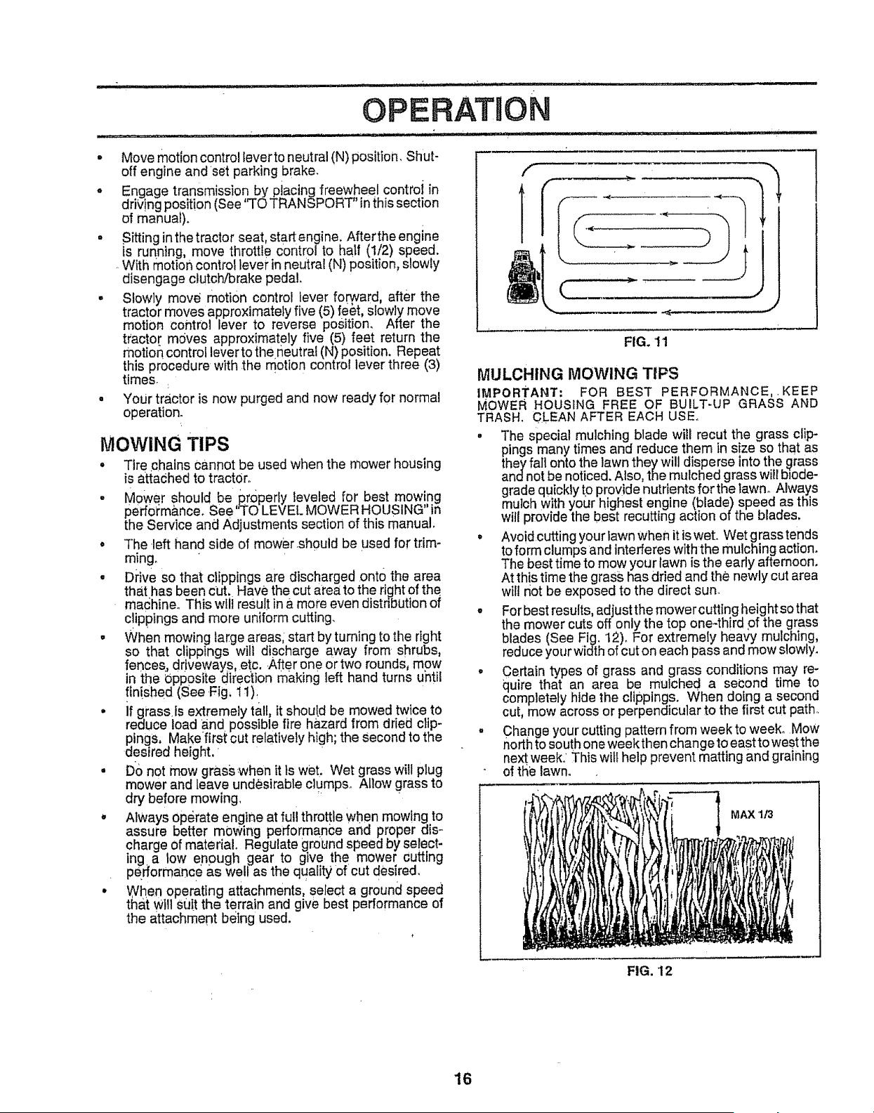
, Movemotion control leverto neutral (N) position. Shut-
off engine and set parking brake.
, Engage transmiss!on by placing freewheel controi in
driving position (See ,,TOTRANSPORT" in this section
of manual).
° Sitting in the tractor seat, startengine. Afterthe engine
is running, move throttle Contro! to half (1/2) speed.
. With motion control level; in neutral (N) position, slowly
disengage clutch/brake pedal.
• Slowly move motion control lever forward, after the
tractor moves approximately five (5) re&t, slowly move
motion control lever to reverse position. After the
tractor moves approximately five (5) feet return the
motion control lever to the neutral (N) position. Repeat
this procedure with .the motion control lever three (3)
times..
• Your tractor is now purged and now ready for normal
operation.
MOWING TIPS
• Tire _chainsCannot be used when the mower housing
is attached to tractor.
• Mower should be ,p.r0perfy leveled for best mowing
perfoi;m&nce. See TO LEVEL MOWER HOUSING" in
the Service and Adjustments section of this manual.
• The left hand side of mower.should be used for trim-
ming.
° D_'ive so that clippings are discharged onto the area
that has been cut. Have the cut area to the fight of the
machine. This wf result in a more even distribution of
c!ippings and mere uniform cutting.
• When mowing large areas; start by turning to the fight
so that clippings will discharge away from shrubs,
fences_ driveways, etc, .After one or two rounds, mow
in the Opposite _irec'tion making left hand turns unti!
fin!shed (See .Fig, i 1)_
° if grass.is extremely tall, it should be mowed twice to
reduce load and possible fire hazard from dried clip-
pings, Makefirst cut relatively high; the Second to the
desired height,
° D0 not mow grasswhen it Is wet. Wet grass will plug
mower and leave undesirable c;umpso Allow grass to
dry before mowing.
, Always operate engine at full throttle when mowing to
assure better mowing performance and proper dis-
charge of material. Regulate grdund speed by select-
ing a low enough gear to give the mower cutting
pefformance a.s well as the quality of cut desired,
• When operating attachments, select a ground speed
that will suit the terrain and give best performance of
the attachment being used.
FIG. 't I
MULCHING MOWING TIPS
IMPORTANT: FOR BEST PERFORMANCE, . KEEP
MOWER HOUSING FREE OF BUILT-UP GRASS AND
TRASH. CLEAN AFTER EACH USE.
° The special mulching blade will recut the grass clip-
pings many times and reduce them in size so that as
they fall onto the lawn they will disperse into the grass
andnot be noticed. Also, the mulched grass will bJode-
grade quickly to provide nutrients for the lawno Always
mulch with your highest engine (blade) speed as this
will provide the best recutting action of the blades.
• Avoid cutting your lawn when it isweL Wet grass tends
to form clumps and interferes with the mulching action.
The best time to mow your lawn is the early afternoon.
At this time the grass has dried and the newly cut area
will not be exposed to the direct sun.
• For best results, adjust the mower cutting height so that
the mower cuts off only the top one-third of the grass
blades (See Fig. 12). For extremely heavy mulching,
reduce your width of cut on each pass and mow slowly.
• Certain types of grass and grass conditions may re-
quire that an area be mulched a second time to
completely hide the clippings. When doing a second
cut, mow across or perpendicu]ar to the first cut path.
- Change your cutting pattern from weekto week° Mow
north to south one week then change to east to west the
next weeko This wilt help prevent matting and graining
of the lawn.
MAX 1/3
FIG, 12
16
CUSTOMER RESPONSIBILITIES
: t _ : ................................ ' , i I I lljll iiiiiiiiiiiiiiii i J I J ILII_I_I_II IIIIMIIIII
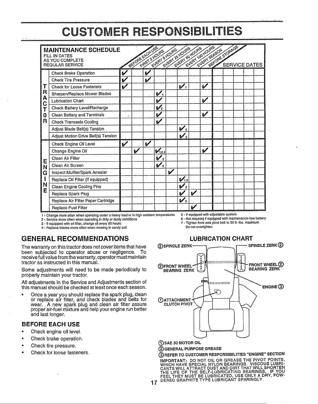
MAINTENANCE SCHEDULE " ._,oe'e./S_/__
AS YOU COMPLETE _ _ ,J, _ _ _. b_.'
REGULAR SERVICE .,,_"_.,_.;/£'_ RV!CE DATES ....
Check Brake Operation _ It_
............................. ; , =
Check Tire Pressure if 6#4
T CheckforLooseFasteners ........ 6/. 1_7
AR Sha_e_ReplaceMowetBlades ........... . _4 .........]
.....LuSr_t OnChart ..............._ ....... LV i t e_' " '
T Check Battery LeveVRec.ha.rge
0 Clean Battery and Terminals _ if __ , :
a Check Transaxle Cooling .... V _' ........ ..........
Adjust Blade Belt(s) Tension _t_'S........
Adjust Motion Drive Belt(s) Tension
" " Check Engine Oil Level Q/
,, ,,
Change Engine Oil I it/ _
Clean Air Filter _4'2 i
E Clean Air Screen i i ........., - _2[ ............
N ,,, ............................. , : ..... : ; ;
G inspect Muffler/SPark Affester ...... if I
I Replace Otl Filter (If equipped) 64_L_ I , ....:
clean Engine €ooii#g Rns . ....... t" . .:.i... :1 ,'_,, ! : ! f t 1
' e,' v' "
Replace Spark Plug
Replace Air Filter Paper Cartridge 6/'_ .
Replace Fuel Filter .......... I
i - Changemore oftenwhenoperallngundera heavyloador in high ambienttemperatures. 5 - if equippedwith adjdetablesystem
2 - Sewlce more oftenwhen operatlt_gin dfriyor dustyconditions. 6 - Not _equked,If equippedwilhmaintenance4reebattery
3 - If equippedWithoilttlter,changeeii eve#/50 hours. 7 - Tightenfront axlepivotbel_to35 tt 4bs, maximum
4 -Replace bladesmoreOftenwhenmowingin sandysoil, Do net overtlgh_en
GENERAL RECOMM ENDATIONS
The warranty on this tractor does not cover items that have
been subjected to operator abuse or negligence. To
receive full value from the warranty, operator must maintain
tractor as instructed in this manual:
Some adjustments will need to be made periodically to
properly maintain your tractor.
All adjustments in the Service and Adjustments section of
this manual should be checked at least once each season°
• Once a year you sl_ould replace the spark plug, clean
or replace air filter, and check blades and belts for
wear.. A new spark plug and clean air filter assure
proper air-fuel mixture and help your engine run better
andlast longer°
BEFORE EACH USE
• Check engine oil level.
• Check brake operation.
, Checktire pressure.
• Check for loose fasteners_
(_)SPINI
LUBRICATION CHART
SPINDLE ZERK (E)
(_FRONT
BEARING ZERK
BEARING ZERK_
¢
CLUTCH PIVOT
'17
{_SAE 30 MOTOR OIL
(_) GENERAL PURPOSE GREASE
(3) REFER TO CUSTOMER RESPONSIBILITIES "ENGINE" SECTION
IMPORTANT: DO NOT OIL OR GREASE THE PIVOT POINTS,
WHICH HAVE SPECIAL NYLON BEARINGS. VISCOUS LUBRI-
CANTS WILL ATTRACT DUST AND DIRT THAT WILL SHORTEN
THE LIFE OF THE SELF-LUBRICATtNG BEARINGS. IF YOU
FEEL THEY MUST BE LUBRICATED, USE ONLY A DRY. POW-
DERED GRAPHITE TYPE LUBRICANT SPARINGLY,
CUSTOM.
.......... ii i, ,i,
TRACTOR
Always observe safety rules when performing any mainte-
nance.
BRAKE OPERATION
If traotor requires more than six (6) feet stopping distance
at high speed in highest gear, then brake must be adjuste&
(See 'q'O ADJUST BRAKE" in the Service and Adjust-
ments sectioP, of this manual).
TIRES
• Mafntain proper air p[essure in all tires (See "PROD-
UCT SPECIEICATIONS" on page 3 of this manual).
• Keep tires flee of gasoline, ott, or insect control chemi-
cals which can harm rubber.
° Avoid stumps, stones, deep ruts, sharp objects and
other: hazards that may cause tire damage:
NOTE; To sea! tire punctures and prevent flat tires due to
slow leaks, tire sealant may be purchased from your local
parts dealer. Tire sealant also prevents tire dry tot and
corrosion.
RESPO LgTmES
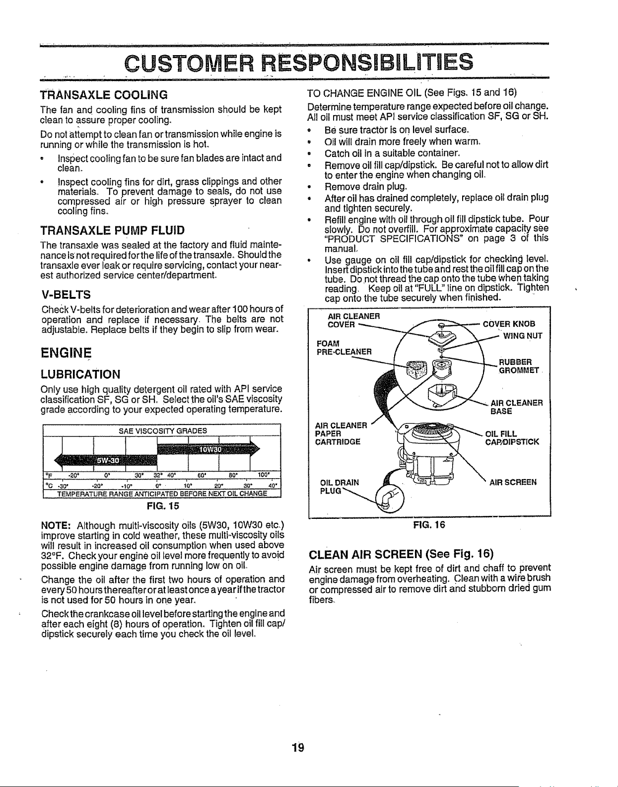
TO SHARPEN BLADE (See Fig. 14)
Care should be taken to keep the blade balanced. An
unbalanced blade will cause excessive vibration and even-
tual damag e to mower and engine.
° The blade can be sharpened with a file or on a grinding
wheel Do not attempt to sharpen while on the mower.
• To check blade balance, you will need a 5/8" diameter
steel bolt, pin, or a cone balancero (When using a cone
balancer, follow the instructions supplied with bal-
ancer).
° Slide blade on to an unthreaded portion of the steel bolt
or pin and hold the bott or pin parallel with the ground.
If blade is baEanced, it should remain in a horizontal
position. If either end of the btade moves downward,
sharpen the heaw end until the blade is balanced.
NOTE: Do not use a nail for balancing b[ade_ The lobes of
the center hole may appear to be centered, but are not.
BLADE CARE
For best resuits moWer blades must be kept Sharp. Re-
place bent or damaged blades.
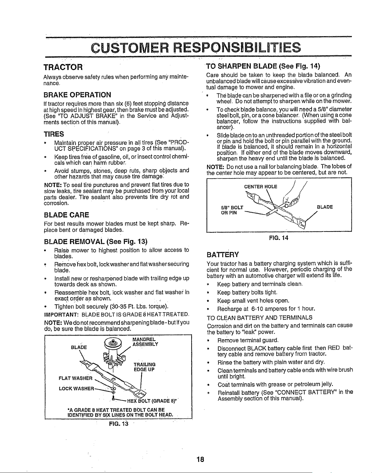
BLADE REMOVAL (See Fig. 13)
• Raise mower to highest position to allow access to
blades°
: Removeflex bolt, Iockwasher and flat washer securing
blade.
• Install new or tesharpened blade with trailing edge up
towards deck as shown.
o Reassemble hex bo!t, lock washer and fiat Washer in
exact order as shown.
° Tighten bolt securely (30-35 Ft. Lbs. torque)i
IMPORTANT'. BLADE BOLT IS GRADE 8 HEATTREATED
NOTE; We do not recommend sharpening blade- but if you
do, be sure the blade is balanced.
MANDREL
BLA_)E ASSEMBLY
\
FLAT WASHIER _,
' HEX BOLT (GRADE 8)'
*A GRADE 8 HEAT TREATED BOLT CAN BE
IDENTIFIED BY S!X LINE S ON THE BOLT HEAD, ,
FIG. 13 _ '
5/8" BOLT
OR PIN
FIG, 14
BATTERY
Your tractor has a battery charging system which is suffi-
cient for normal use_ However, periodic charging of the
battery with an automotive charger will extend its life.
o Keep battery and terminals clean.
• Keep battery bolts tight°
° Keep small vent holes open.
• Recharge at 6-10 amperes for 1 hour.
TO CLEAN BATTERY AND TERMINALS
Corrosion and dirt on the battery and terminals can cause
the battery to "leak" power.
° Remove terminal guard.
° Disconnect BLACK battery cable first then RED bat-
tery cable and remove battery from tractor.
• Rinse the battery withp_ainwater and dry.
- Clean terminals and batte_ cable ends with wire brush
Ufitil brighL
° Coat terminaEs with grease or petroleum jelly.
• Reinstall battery (See "CONNECT BATTERY" in the
Assembly section of this manual).
18
CUSTOMER
TRANSAXLE COOLING
The fan and cooling fins of transmission should be kept
clean to assure proper cooling.
Do not attempt to clean fan or transmission while engine is
running or while the transmission is hot.
• Inspect cooling fan to be sure fan blades are intact and
clean.
• inspect cooling fins for dirt, grass clippings and other
materials. To prevent damage to seals, do not use
compressed air or high pressure sprayer to clean
cooling fins°
TRANSAXLE PUMP FLUID
The transaxfe was sealed at the factory and fluid mainte-
nance isnot required forthe life of the transaxle. Should the
transaxle ever !eak or require servicing, contact your near-
est authorized service center!department.
V-BELTS
Check V-belts for deterioration and wear after 100 hours of
operation and replace if necessary. The belts are not
adjustable° Replace belts if they begin to slip from wean
ENGINE
LUBRICATION
Only use high quality detergent oil rated with API service
classification SF, SG or SHo Select the oil's SAE viscosity
grade according to your expected operating temperature,
SAE VISCOSITY GRADES
4 wmmt
°F -_0 ° 0" 30" _32" 40_ 60" 80 ° 100"
°,C ;30 _, ,, _20" ,,, -t0" ,,q_,,,'...... "_O' , 20°,..............8,0' 40"
TEMPERATURE RANGE ANTICIPATED BEFORE NEXT OIL CHANGE
FIG. 15
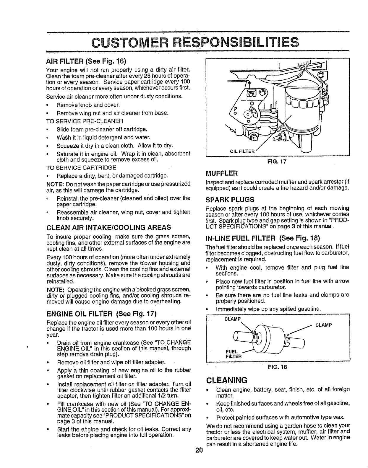
TO CHANGE ENGINE OIL (See Fig& 15 and 16)
Determine temperature range expected before oil change.
All oil must meet API service classification SF, SG or SH.
o Be sure tractor is on level surface.
• Oil will drain more freely when warm,
• Catch oil in a suitable container°
• Remove oil fill cap/dipstick° Be careful not to aIlow dirt
to enter the .engine when changing oil.
• Remove drain plug,
• After oil has drained completely, replace oil drain plug
and tighten securely.
• Refill engine with oil through oil fl!l dipstick tube. Pour
slowly. Do not overfill For approximate capacity see
"PRODUCT SPECIFICATIONS" on page 3 of this
manual
° Use gauge on oil fill cap/dipstick for checking level.
Insert dipstick into the tube and rest the oil fill cap on the
tube. Do .notthread the cap onto the tube when taking
reading, Keep oUat "FULL" line on dipstick. Tighten
cap onto the tube securely when finished°
AIR CLEANER
COVER
FOAM
PRE-CLEANER
COVER KNOB
WING NUT
RUBBER
IROMMET,
_iR CLEANER
BASE
AIR CLEANER
PAPER _IL FILL
CARTRIDGE CAP/DIPSTICK
OIL DRAIN AIR SCREEN
NOTE: Although multi-viscosity oils (5W30, 10W30 etc.)
improve starting in coId weather, these multiwiscosity oils
will result in increased oil consumption when used above
32°F. Check your engine oil level more frequently to avoid
possible engine damage from running low on oil.
Change the oil after the first two hours of operation and
every 50 hours thereafter or at least once a year ifthe tractor
is not used for 50 hours in one year°
Check the crankcase oil level before starting the engine and
after each eight (8) hours of operation. Tighten oil fil! cap/
dipstick securely each time you check the oil level
FIG. 16
CLEAN AIR SCREEN (See Fig. 16)
Air screen must be kept free of dirt and chaff to prevent
engine damage from overheating. Clean with a wire brush
or compressed air to remove dirt and stubborn dried gum
fibers.
19
CUSTOMER RESPONSI L ES
AIR FILTER (See Fig, 16)
Your engine will not run properly using a dirty air filter.
Clean the foam pre-cleaner after every 25 hours of opera-
tion or every season. Service paper cartridge every 100
hours of operation or every season, whichever occurs first.
Service air cleaner more often under dusty conditions.
• Remo_'e knob and cover.
° Remove wing nut and air cleaner from base.
TO SERVICE PRE-CLEANER
• Slide foam pre-cleaner off cartridge.
• Wash it in liquid detergent and water.
° Squeeze it dry in a clean cloth. Allow it to dry.
° Saturate it in engine oil. Wrap it in clean, absorbent
cloth and squeeze to remove excess oil.
TO SERVICE CARTRIDGE
o Replace a dirty, bent, 0r damaged cartridge.
NOTE: Do not wash the paper cartridge or use pressurized
air, as this will damage the cartridge.
• Reinstal! the pre-cleaner (cleaned and oiled) over the
paper cartridge,
• Reassemble air cleaner, wing nut, cover and tighten
knob securely.
CLEAN AIR INTAKEICOOLING AREAS
o
OIL FILTER
FIG, 17
MUFFLER
Inspect and replace corroded muffler and spark arrester (if
equipped) as it could create a fire hazard andtor damage.
SPARK PLUGS
Replace spark plugs at the beginning of each mowing
season or after every 100 hours of use, whichever comes
_r_ SP_rck,_cgtyp(_d ogaps;_,;go_St_hsOmW2nfuaPROD
To insure proper cooling, make sure the grass screen,
cooling fins, and other external surfaces of the engine are
kept clean at all times.
Every 100 hours of operation (more often under extremely
dusty, dirty conditions), remove the blower housing and
other cooling shrouds. Clean the cooling fins arid external
surfaces as necessary. Make sure the cooling shrouds are
reinstalled.
NOTE." Operating the engine with a blocked grass screen,
dirty or plugged c0ol ng f ns, and/or, cooling shrouds' re-
moved will cause engine damage due to overheating_
ENGINE OiL FILTER (See Fig, 17)
Replace the engine oil filter every season or every other ol1
change if the tractor is used more than I00 hoUrs in one
year.
• Drain oil from engine crankcase (See "TO CHANGE
ENGINE. OtL" in this section 0fthiS manual; through
step remove drain p!ug).
° Remove oil filter and wipe off filter adapter.
• Apply a thin coating of new engine oil to the rubber
gasket on replacement oil filter.
• install replacement oil filter on _ter adapter. Turn oil
filter clockwise until rubber gasket contacts the filter
adapter, then tighten fi!ter an additional 1/2 turn.
° Fill crankcase wi{h new oil (See 'q'O CHANGE EN-
GINE.OIL in this section of this manual), For appr0xF
mate capacity see "PRODUCT SPECIFICAT!ONS" o0
page 3 of this manual
, Start the engine and check for oil leaks. Correct any
leaks before placing engine into full operation.
IN-LINE FUEL FILTER (See Fig. !8)
The fuel filter shouldbe replaced once each season, iffuel
filter becomes clogged, obstructingfue! ftow to carburetor,
replacement is require d .
° With engine cool, remove filter and plug fuel tine
sebtion&
° Place new fue! filter in position in fuel line with arrow
pointing towards carburetor°
• Be sure there are no fuel line leaks and clamps are
properly positioned°
, Immediately wipe up any spilled gasoline.
CLAMP
' CLAMP
FILTER
FIG. 18
CLEANING
• Clean engine, battery, seat, finish, etc. of all foreign
matter,
° Keep finished surfaces and wheels free of all gasoline,
oil, etc.
• Protect painted surfaces with automotive type wax.
We do not recommend using a garden hose to clean your
tractor unless the electrical system, muffler, air filter and
carburetor are covered to keep water out. Water in engine
can result in a shortened engine life.
20
U i ! !ii!i!,, I l,ll_llP I ............ ................................ : --" " ......... ' "I I_ _Ir_ "
SERVICE A DADJUSTMENTS
CAUTION: BEFORE PERFORMING ANY SERVICE OR ADJUSTMENTS:
o Depress clutch/Drake pedal fully and set parking brake.
° Place motion control lever in neutral (N) position.
° Place attachment clutch in "DISENGAGED" position.
° Turn ignition key "OFF" and remove key.
° Make sure the blades and all moving parts have completely stopped.
° Disconnect sparkplug wire from spark plug and place wire whereit cannot come in contact with
plug.
, ............. , ............ , i, ,,_ _,_,i,,l_,l i i_l ,ill i,i _J,,iiJ,, , _ i i,_lm
. +
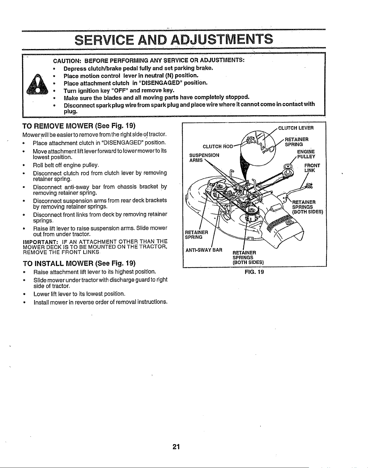
TO REMOVE MOWER (See Fig. 19)
Mower will be easier to remove from the right side of tractor.
• Place attachment clutch in "DISENGAGED" position_
o Move attachment lift lever forward to lower mower to its
lowest position+
• Roll belt off engine pulley.
= Disconnect clutch rod from clutch lever by removing
retainer spring.
° DiSconnect anti-sway bar from chassis bracket bY
removing retainer spnng.
° Disconnect suspension arms from rear deck brackets
by remOving retainer springs_
. Disconnect front links from deck by removing retainer
springs..
• Raise lift lever to raise suspension arms, Slide mower
out from under tractor.
IMPORTANT' IF AN ATTACHMENT OTHER THAN THE
MOWER IJECK IS TO BE MOUNTED ON THE TRACTOR,
REMOVE THE FRONT LINKS.
TO INSTALL MOWER (See Fig. 19)
° Raise attachment lift lever to its highest position,
° Slide mower undertractorwith discharge guardto right
side of tractor+
° Lower lift lever to its lowest position.
CLUTCH
SUSPENSION
ARMS
LEVER
RETAINER
SPRING
ENGINE
FRONT
LINK
SPRINGS
(BOTH SIDES)
RETAINER
SPRING
ANTI-SWAYBAR
RETAINER
SPRINGS
(BOTH SIDES)
FIG. 19
• Install mower in reverse order of removal instructions,
21
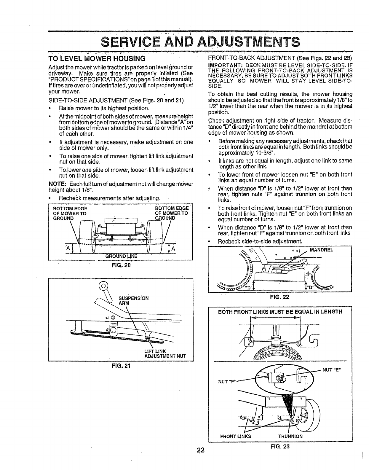
T0 LEVEL MOWER HOUSING
Adjust the mower while tractor is parked on level ground or
driveway, Make sure tires are properly inflated (See
"PRODUCT SPECIFICATIONS" on page 3 of th!s manual).
Iftires are over or Underinflated, you will not properly adjust
your mower°
SIDE-TO-SIDE ADJUSTMENT (See Figs° 20 and 21)
° Raisi_ mower to its highest position,,
• At the midpoint of both sides of mower, measure height
frombottom edgeo[mower t0 ground.. Distance"A" on
both sides of mower _,houtdbe the same Orwithin 1/4"
of each other,,
• If adjustment ls necessary, make adjustment on One
side Of mower on y. " "
• To ra!se (me side of mower, tighten lift link ;_djustment
nut on that side,
• To.lower one side of mower, loosen lift link adjustment
nut on that side,
NOTE: Each,full turn of adjustment nut wtll change mower
height about 1/8",
• Recheck measurements after adjusting
BOTTOM EDGE' BOTTOM EDGE
OF MOWER TO OF MOWER TO
GROUND GROUND
\
GROUND L!NE
F!G, 20
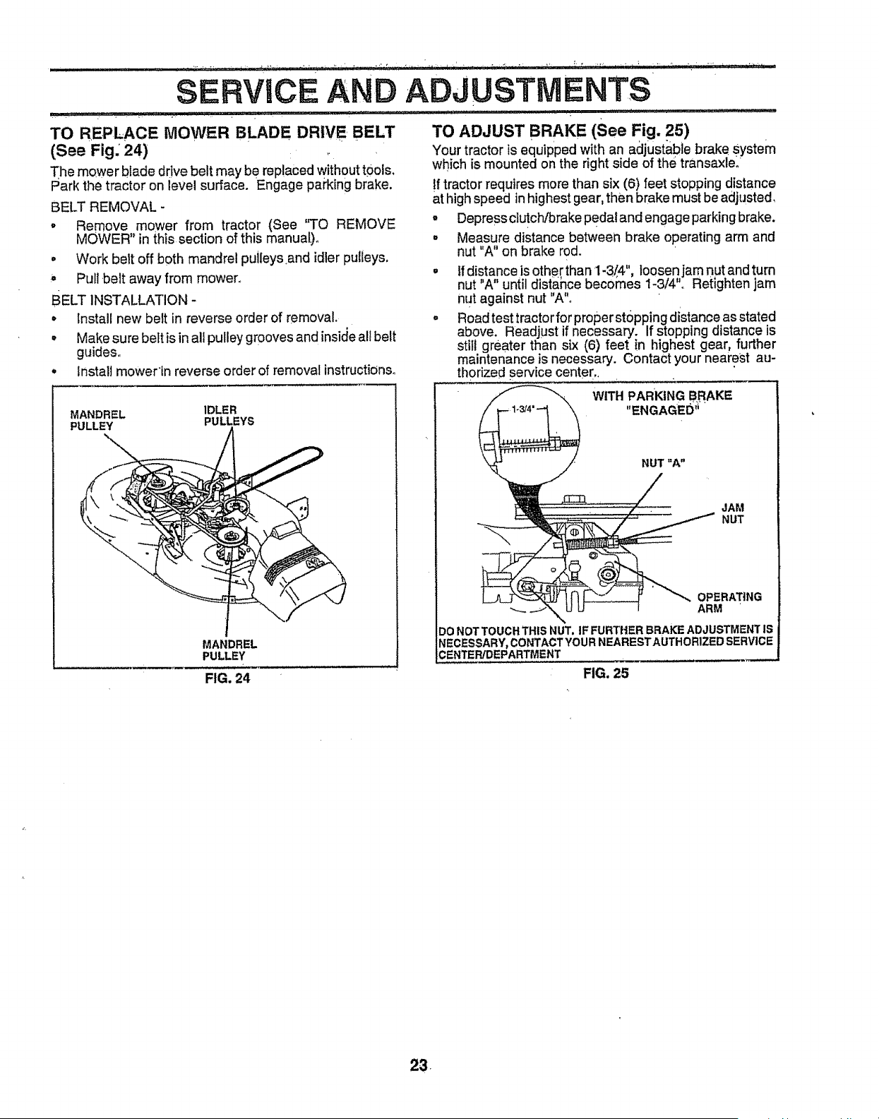
ERONT-TO-BACK ADJUSTMENT (See Figs. 22 and 23)
IMPORTANT: DECK MUST BE LEVEL SIDE-TO-SIDE, IF
THE FOLLOWING FRONT-TO-BACK ADJUSTMENT IS
NECESSARY, BE SURE TO ADJUST BOTH FRONT LINKS
EQUALLY SO MOWER WILL STAY LEVEL SIDE-TO m
SIDEo
To obtain the best cutting results, the mower hodsing
should be adjusted so that the front isapproximately 1/8" to
1/2"lower than the rear when the mower is in its highest
position,
Check adjustment on right side of tractor, Measure dis-
tance "D" directly in front and behind the mandrel at bottom
edge of mower housing as shown,
• Before making any necessary adjustments, checkthat
both front links are equal in length, Both linksshould be
approximately t0-3/8",
° If links are not equal in length, adjust one link to same
lengthas other link,
• To lower front of mower loosen nut "E" on both front
links an equal number of turns.
- When distance "D" is 1/8" to 1/2" lower at front than
rear, tighten nuts "F" aga_insttrunnion on both front
links,
° To raise front of mower, loosen nut"F" from trunnion on
both front links. Tighten nut "E" on both front links an
equal number of turns.
° When distance "D" is 1/8" to 1/2" lower at front than
rear, tighten nut "F" against trunnionon both front links,
- Recheck side-to-side adjustment.
MANDREL
SUSPENSION
ARM
LIFT LINK
ADJUSTMENT NUT
FIG. 21
, k
FIG. 22
BOTH FRONT LINKSMUST BE EQUAL iN LENGTH
NUT "E"
NUT "F"
FRONT LINKS TRUNNION
FIG. 23
22
i
SERVICE AND
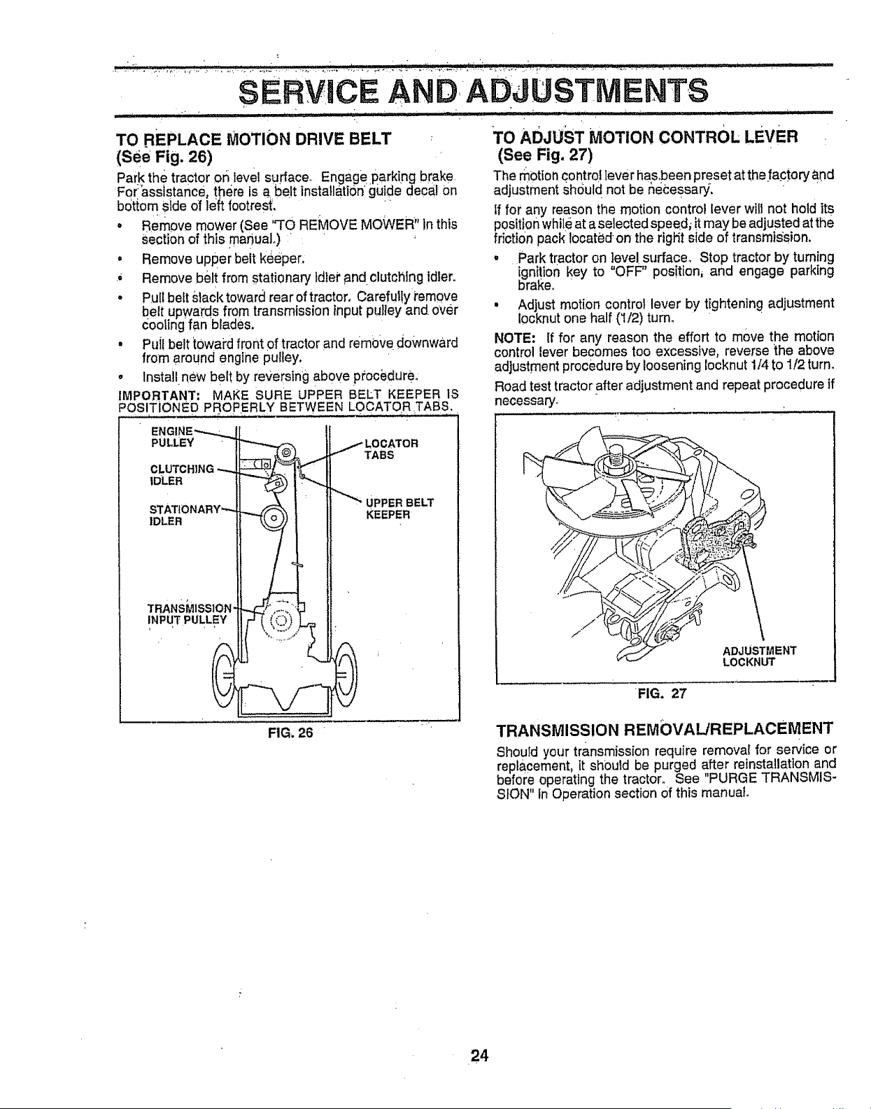
TO REP .,L_CE MOWER BLADE DRIVE, BELT
(See Fig; 24) ,.
The mower blade drive belt may be replaced without t0ols_
Park the tractor on level surface. Engage parking brake.
BELT REMOVAL -
ADJUSTMENTS
TO ADJUST BRAKE (See Fig. 25)
Your tractor is equipped with an adjustable brake system
which is mounted on the right side of the transaxle__
If tractor requires more than six (6) feet stopping distance
at high speed in highest gear, then brake must be adjusted,
o Remove mower from tractor (See "TO REMOVE
MOWER" in this section of this manual),
° Work belt off both mandrel puileys_and idler pulleys.
, Pull belt away from mower.,
BELT INSTALLATION -
o Install new belt in reverse order of removal,
• Make sure belt is in alt pulley grooves and insic_eall belt
guides,
° install mowertn reverse order of removal instructions,
MANDREL IDLER
PULLEY PULLEYS
MANDREL
PULLEY
FIG. 24
° DepressclutciVbrake Pedaland engage parking brake.
° Measure distance between brake operating arm and
nut "A" on brake rod.
° tf distance isothe[than 1-3/4", loosen jam nut and turn
nut "A" until distance becornes 1-3/4", Retlghten jam
nut against nut "A"_
° Road test tractorfor proper stopping distance as stated
above. Readjust if necessary, If stopping distance is
still greater than six (6) feet in highest gear, further
maintenance is necessary. Contact your nearest au-
thorized service center,,
WITH PARKING BRAKE
"ENGAGED"
NUT "A"
JAM
NUT
OPERATING
---.. ARM
DO NOTTOUCHTHtS NUT, IFFURTHER BRAKEADJUSTMENTIS
NECESSARY, CONTACTYOURNEARESTAUTHORIZEDSERVICE
FIG. 25
53.
TO REPLACE MOTION DRIVE BELT
(See Fig. 26)
Park the tractor or_ tevel surfaceo Engage parking brake,
For:assistance, there is a, be t installatitJn_guidedecal On
botio m side of left footrest', ' . " "
• Remove moWer (See ,,TO REMOVE MOWER" In this
Sectionof this mar}uaL) " •
= Remove upper belt keeper.
,, Remove ,belt from stationary ldiei" and clutching idler.
• P,u[1belt slack toward rear of tractor, Carefut!ytem0ve
belt upwards from transmission inputpulley and. over
coolingfan blades.
• PuJ{belt t0wai'd front of tractor and remove downward
from around engine pulley,
° Installnew belt by reversing above pr'oci_dure:
IMPORTANT; MAKE SURE UPPER BELT KEEPER IS
POSITIONED PROPERLY BETWEEN LOCATOR TABS.
ENGINE-_--_
PULLEY " _ /LOCATOR
C LUTC HIN G "-_ _, ,_ "" TABS
II "_J I ' _ UPPERBELT
STATIONARY"--- LL _", I ' ,- .....
IDLER II__! _==v=N
TRANS MISSION' ]"_f,-'-,,.""_ J I
INPUT PULLEY tl _ { ( _:::-_) } _,
FIG. 26 "
TO ADJUST MOTION CONTROL LEVER :
(See Fig. 27)
The motion control lever hasbeen preset at the fa.ctory and
adjustment shduld not be _et:essa_,
If for any reason the motion control lever will not hold its
position while at a selected speedl it may be adjusted at the
friction pack located on the rtgtit side of transmts'sion,
° Park tractor on ].eve!surface. Stop tractor by turning
ignition key to OFF' position, and engage parking
bra_e. '
• Adjust motion control lever by tightening adjustment
10cknutone half (!/2) turn.
NOTE: If for any reason the effort to move the motion
control lever becomes too excessive, reverse _he above
adjustment procedure by loosening locknut 1/4 to 1/2 turn,
Road test tractor after adjustment and repeat procedure if
necessary'.
i
ADJUSTMENT
LOCKNUT
FIG. 27
TRANSMISSION REMOVAL/REPLACEMENT
Should your transmission require removal for service or
replacement, it should be purged after reinstallation and
before operating the tractor. See "PURGE TRANSMIS-
SION" in Operation section of this manual.
24
ERVIC!E AND ADJUSTNIENTS
i
=
=
.................................. . .... r , ..... r........... ,,_,,,.................;"''" _ _:;;:_ :_:i;' ::_
TO ADJUSTSTEERING WHEEL A_!GNMENT
if steering whee! Crossbars are not hor_zonta! (left to right)
whenwheels are positionedstraight forward, remove steer-
ing wheel and reassemble per instructionsin _.heAssembly
section of this manual,
FRONT WHEEL TOE.IN/CAMBER
The front wheel toe-in and camber are not adjustable on
your tractor. If damage has occurred to affect the front
wheel toe-in or camber, contact you_"nearest authorized
service center/departme.nL
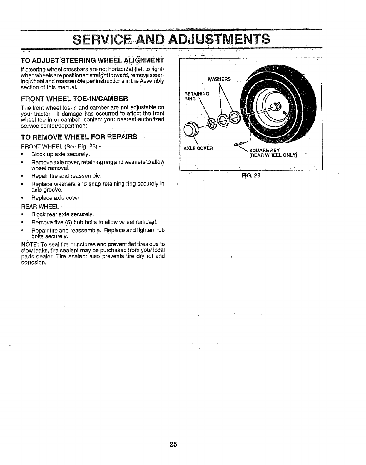
TO REMOVE WHEEL FOR REPAIRS
FRONT WHEEL (See Fig. 2 8) -
• Block up axle securely.
• Remove axle cover, retaining ring and washers to allow
wheel removal,
• Repair tire and reassemble,
• Replace washers and snap retaining ring securely ih
axle groove. ,
• Replace axle cover.
REAR WHEEl,,-
• Block rear axle securely.
o Remove five (5) hub bolts to allow wh&el removal,
° Repair tire and reassemble, Replace arid tighten hub
bolts securely. "
NC)TE: To Seal tire punctures and prevent'flat tires due to
stow leaks, tire sealant may be purchased from your local
pads dealer. Tire sealant also prevents tire dry rot and
corrosion,
WASHERS
RETAINING
RING
!
_SQUAREKEY
(REARWHEELONL_
FIG. 28
25
. :..
SERVmCEA
ADJUSTMENTS
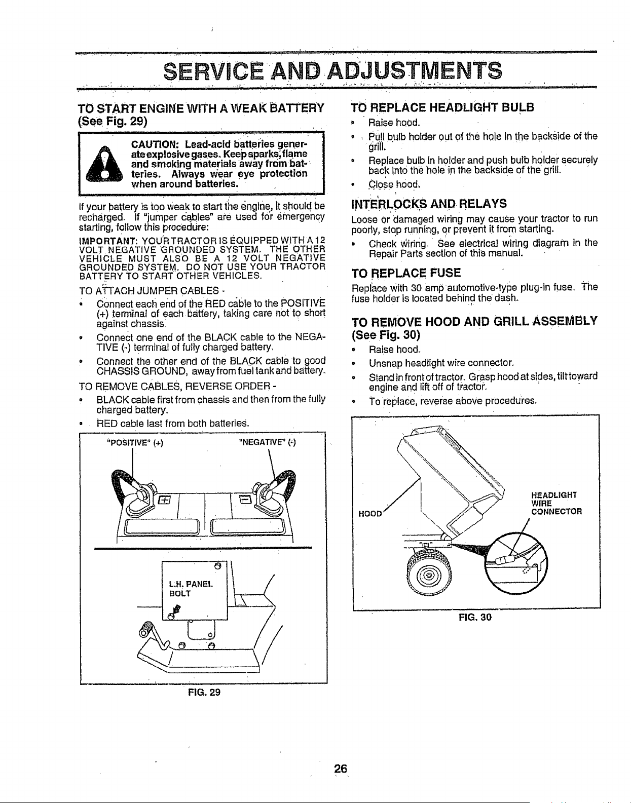
TO START ENGINE WiTH A WEAK BATTERY
(See Fig. 29)
CAUTION: Lead-acid battei:ies gerber-
ateexptosivegases. Keepsparks;flame
and smoking materials away from bat-_.
teries. Always ,,_ieareye protection
when around batteries.
H_HH"" I Jl _ IJ I]lJ]'l = i IUII"III[ _
if your battery is too weak to start {he engir_e, it should be
recharged. If "jumper cables" are used f0_remerge'ncy
starting, follow this procedure: •
IMPORTANT: Your TRACTOR IS EQUIPPED WITHA 12
VOLT.NEGATIVE GROUNDED SYSTEM: THE OTHER
VEHICLE MUST ALSO BE A 12 VOLT NEGAT}VE
GROUNDED SYSTEM. DO NOT USE YOUR TRACTOR
BATT.ERY TO START OTHER VEHICLES.
TO A:Tt"ACH JUMPER CABLES -
' Connect each end of the RED cabte to the POSIT]VE
(+) tern'iinal of each battery, taking care notto short
against chassisl
• Connect one end of the BLACK cable to the NEGA-
TIVE (-) terminal of fully charged batter,/,
= Connect the other end of the BLACK cable to good
CHASSIS GROUND, away from fuel tank and battery°
TO REMOVE CABLES, REVERSE ORDER -
, BLACK cable first from chassis and then from the fully
charged battery_
• . RED cable last from both batteries°
' _'POSITIVE" (+) "NEGATIVE" '(9
BOLT
i L IHlll llllll 'll.ll,
/
FIG. 29
TO REPLACE HEADLIGHT BULB
, Raise hood.
• . pU!i bulb holder out of the hole In the backside of the
grill.
• Replace bulb In holder and push bulb holder securely
back into the 'hQle in the backside ofthe grill. '
o .Ct#seh0o d,
INTERLOCK S AND RELAYS
Loose Or damaged wiring may cause your tractor to run
poorly, stop running, or prevent it from starting.
• Check wiring., See electrical wiring diagram in the
Repair Parts section of this manual. .
TO REPLACE FUSE
Replace With 30 amp automotive-type plug-in fuse_ The
fuse holder is located behind the dash..
TO REMOVE HOOD AND GRILL ASSEMBLY
(See Fig. 30)
, Ral.se hood.
. Unsnap headlight wire connector.
• Stand in front of tractor. Grasp hood at sides, tilttoward
engine and lift off of t_'actoi_o
• To replace, i'evew:seabove pr0cedures.
_OOD '\\,
\
HEADLIGHT
WIRE
CONNECTOR
FIG, 30
26
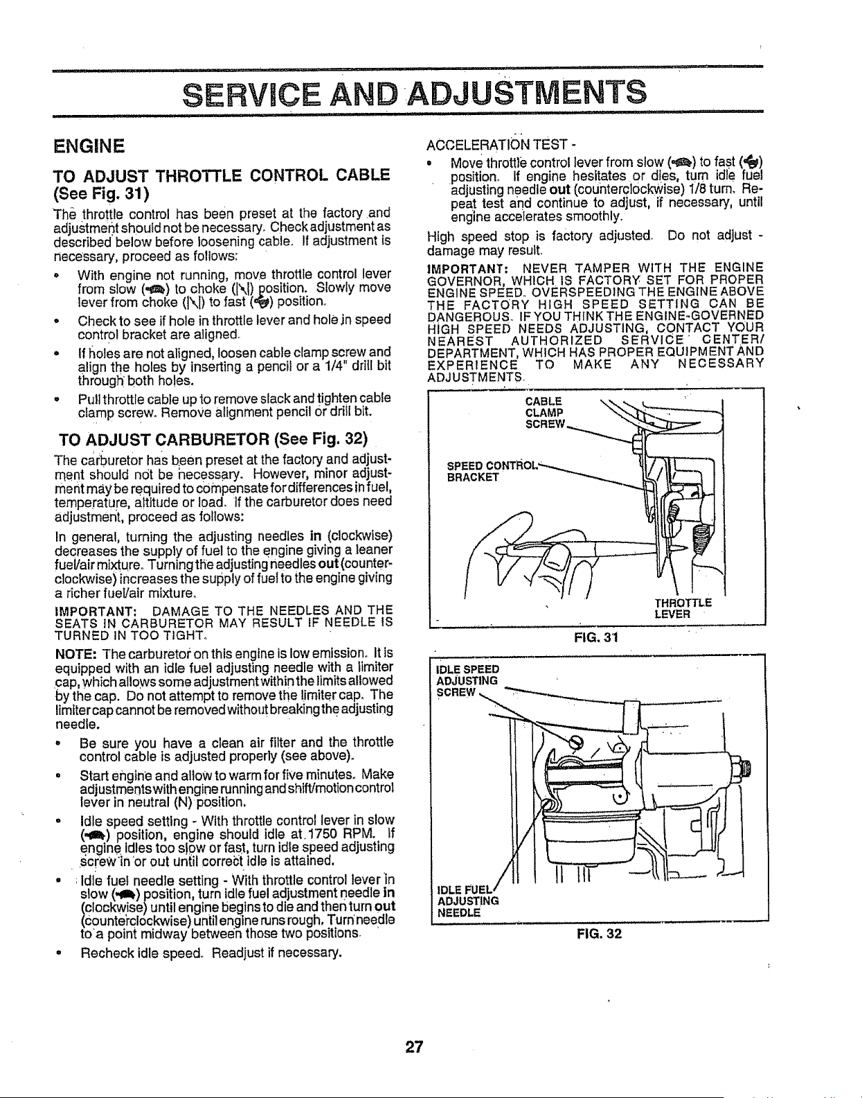
SERVICE AND ADJUSTMENTS
..... :.......................... , , , H,
ENGINE
TO ADJUST THROTTLE CONTROL CABLE
(See Fig. 31)
The throttle control has been preset at the factory and
adjustmeot should not be necessary. Check adjustment as
described below before loosening cable° If adjustment is
necessary, proceed as follows:
o With engine not running, move throttle control lever
from slow (-t_) to choke (I\) position. Slowly move
lever from choke (\1) to fast (_) posit ono
° Check to see if hole in throttle lever and hole jn speed
control bracket are aligned.
- tf holes are not aligned, loosen cable clamp screw and
align the holes by inserting a pencil or a 1/4" drill bit
through' both holes.
° Pull throttle cable up to remove slack and tighten cable
clamp screw. Remove alignment pencil or drill bit.
TO ADJUST CARBURETOR (See Fig. 32)
The ca.rburetor has been preset at the factory and adjust-
rqent should not be hecessary. However, minor adjust-
ment may be required to compensate for differences infuel,
temperature, altitude or 10ad. if the carburetor does need
adjustment, proceed as follows:
In general, turning the adjusting needles in (clockwise)
decreases the supply of fuel to the engine giving a leaner
fuel/air mixtu.reoTurningthe adjusting needles out(counter-
clockwise) increases the supply of fuel to the engine giving
a richer fueVair mixture°
IMPORTANT: DAMAGE TO THE NEEDLES AND THE
SEATS tN CARBURETOR MAY RESULT IF NEEDLE tS
TURNED IN TOO TIGHT°
NOTE- The carburetor on thisengine is low emission° It is
equipped with an idle fuel adjusting needle with a iimiter
cap, which a lows some adjustment within the limits allowed
by the cap. Do not attempt to remove the !imite,r cap. The
limiter cap cannot be removed without breaking the adjusting
needle.
° Be sure you have a clean air filter and the throttle
control cable is adjusted properly (see above).
• Start engine and allow to warm for five minutes. Make
adjustmentswith engine running and shift/motion control
lever in neutral (N)positlon.
° Idle speed setting - With throttle control lever in slow
(,,g_) position, engine should idle at.1"750 RPM:. If
engine idles too slow or fast, turn idle speea adjusting
screw"in or out ur{iii correi_iidle is attained,
° _Idle fuel needle setting - With throttle control lever'in
slow (,_I_) position, turn idle fuel adjustment needle in
(clockwise)until engine begins to die and then turn out
(counterclockwise)until engine runs rough, Turn'needle
toa point midway between those two positions. '
° Recheck idle speed° Readjust if necessary.
ACCELERATI_)N TEST-
. Move throttle control lever from slow (,_!) to fas.t (,{y)
position° tf engine hesitates or dies, turn idle fuel
adjust ng needle out (counterclockwise) 1/8 turn. Re-
peat test a_ndcontinue to adjust, if necessary, until
engine accelerates smoothly.
High speed stop is factory adjusted. Do not adjust -
damage may resutL
IMPORTANT: NEVER TAMPER WITH THE ENGINE
GOVERNOR, WHICH IS FACTORY SET FOR PROPER
ENGINE SPEED° OVERSPEED1NG THE ENGINE ABOVE
THE FACTORY HIGH SPEED SETTING CAN BE
DANGEROUS. IF YOU THINK THE ENGINE-GOVERNED
HiGH SPEED NEEDS ADJUSTING, CONTACT YOUR
NEAREST AUTHORIZED SERVICE CENTER/
DEPARTMENT, WHICH HAS PROPER EQUIPMENT AND
EXPERIENCE TO MAKE ANY NECESSARY
ADJUSTMENTS.
SPEEDCONTROL"_',,.*_.._ ,_
BR
THROTTLE
LEVER
FIG, 31
,DLESPEED
ADJUSTING
/
FUEL/-- I
IDLE
ADJUSTING
NEEDLE
FIG. 32
27
• , • • ........
STORAG
....................................... !
Immediately prepare your tractor for storage at the end of
the season or if the tractor wilt not be used for 30 days or
more°
u/11/11111 .................................. -
CAUTION: Never store the tractor with
gasoline in the tank inside a building
where fumes may reach an open flame
or spark. Allow the engine to cool
before storing in any enclosure.
TRACTOR
RemoVe mower:from tractor for winter Storage_ When
mower is to be stored for a period of time, clean it thor-
oughly, remove all dtr_, grease, leaves, etc. Store in a
cl_ean,dry area: . .
. Glean entire tractor (See"CLEANING"in the Customer
Responsibi!ittes section of thismanual). " " "
. Inspect and replace belts, if necessary (See belt re-
placement instructionsin the Service and Adjustments
section Of this manual)°
• Lubricate as shown in the Customer ResPonsibilities
section of this manual.
,, Be sure that all nuts, bolts and screws are securely
fastened. Inspect moving parts for damage, breakage
and Wear, Rep ace if necessary.
o Toucld UP alt rusted or chipped paint surfaces; sand
Ilgh_ly before painting.
BATTERY
• Fully charge the battery for storage°
° After a period of time in storage, battery may requi_'e
recharging.
' To help prevent corrosion and power leakage during
long periods of storage, battery cables Shout€[=be
d sconnected and batten.,'Cleaned thorougN_](see"TO
CLEAN BATTERY AND TERMINALS" in the Cus-
tomer Responsibilities section of this manuaf)_
• After cleaning, leave cabtes disconnected and place
cables Where they Canhot€ome in contact with battery
terminals.
• Be sure battery drain tube is securely attached.
° If battery is removed from tractor for storage, do not
store battery directly on concrete or damp surfaces.
ENGINE
FUEL SYSTEM
IMPORTANT: IT IS IMPORTANT TO PREVENT GUM
DEPOSITS FROM FORMING IN ESSENTIAL FUEL
SYSTEM PARTS SUCH AS CARBURETOR, FUEL FILTER,
.FUEL HOSE, OR TANK DURING STORAGE. ALSO,
EXPERIENCE INDICATES THAT ALCOHOL BLENDED
FUELS (CALLED GASOHOL OR USING ETHANOL OR
METHANOL) CAN ATTRACT MOISTURE WHICH LEADS
TO sEPARATION AND FORMATION OF ACIDS DURING
STORAGE. ACIDIC GAS 'CAN DAMAGE THE FUEL
SYSTEM OF AN ENGINE WHILE IN STORAGE°
° Drain the fuel tank.
• Start the engine and let it run uritil the fuel lines and
carburetor are empty°
° Never use engine Orcarburetor cleaner produc;tsin the
fuel tank or permanent damage may occur_
° Use fresh fuel next season.
NOTE: Fuel stabilizer is an acceptable alternative in
minimizing the formation of fuel gum deposits during stor-
.age. Add stabilizer to gasoli0e in fuel tank or storage
container. Always !ollow the mix ratio found on stabilizer
container. Run engine at least 10 minutes after adding
stabiiizer to atlowthe stabilizer to reach the carburetor. Do
notdrain the gas tank and carburetor ffusing fuel stabilizer,
ENGINE OIL
Drain oil iwith engine warm) and replace withclean engine
oil. (See "ENGINE" in the Customer Responsibilities
section of this manual).
CYLINDERS
° Remove spark plug(s).
° Pour one ounce of oil through spark plug hole(s) into
cylinder(s),
• Tum ignition key to"START" position for afew seconds
to d!stribute oil
,; Replace with new spark plug(s),
OTHER
° Do not store gasoline from one season to another,
= Replace your gasoline can if your can starts to rust.
Rust and/or dirt in your gasoline wil! cause problems.
° f possible, store your tractor indoors and cover it to
give protection from dust and dirt.
° Cover your tractor with a suitable protective cover that
does not retain moisture. Do not use plastic. Plastic
cannot breathe which allows condensation to form and
will cause your tractor to rust.
IMPORTANT: NEVER COVER TRACTOR WHILE ENGINE
AND EXHAUST AREAS ARE STILL WARM.
28

PROBLEM
Will not start
Hard to start
Engine wfli not turn over
i i iii1,,
Engine Clicks but will not
start
Loss of power
Excessive vibration
CAUSE
lr Out of fuel
2. Engine riot"CHOKED" properly-
3. Engine flooded.
4, Bad spa[k ,plug,
5, Dirty air filter,.
6° Dirty fuel fUter,
7. Water in fuel
B, Loose or damaged wiring
9o Carburetor out of adjustment
10.. Engine yalves out of adjustment
1,, Dirty air filter.
2. Bad spark plug,
3. Weak or dead battery
4o Dirty fuet filter.
5° Stale or dirty fuel.
6_ Loose or damaged wldng,
7_ Carburetor out of adjustment,
8. Engine valves out of adjustment,
r,, ,;,,,,.;,__ ,
1,, ClutchfDrake pedal net depressed.
2. Attachment =clutch is engaged,
3 Weak or dead battery
4. Blown fuse°
5, Corroded battery terminals,
6, Loose or damaged wiring,
7. Fau ty ign!tiqn switch.
8_ FauLty solenoid or starter,
9. Faulty operator presence switch(es)_
JLIILI I'J I'1 _[ 'J IIJ , I I1'1I_1 I IIJ I '1 IIIl'
Io Weak or dead battery.
2. Corroded battery terminals.
3, Loose or damaged wir_ng.
4. Faulty solenald or starter,
i
1. Cut_Jngtoo much grass/too fasL
2. Throttle tn "CHOKE" position,
3o But]d-up of grass, leaves and trash under mower°
4. Dirty air filter.
5, Low oil ieveIldtrty oIL
6o F'aultyspark p!ug,
7, OIffyfuel filter.
B,, Stale or dirtyfuel.
9. Water In fuel,,
t0. Sparkplug wire loose,
11. Dirtyengine air screen/fins.
12, Dirt_//clogged muter.
13. Loose or damaged wiring.
14., Carburetor out of adlustmenL
15. Engine vaJves out of adjustment,
1. Worn, bent or loose blade.
2,, Bent blade mandrel°
3_ Loose/damaged part(s),
CORRECTION
1_, Fill fuel tank,
2. See 'TO START ENGINE" in Operation sac!ion,,
3. Wait severer minutes before attempting to start
4. Replace spark plug,
5. Clean/replace air filter
6, Replace fuel filter,,
7,, Drain fuel tank and carburetor, refill tank with fresh
gasoline and replace i'uel fiItei'.
B_ Check all widng,
9,, See "To Adjust Carburetor" in Service Adjustments
section,
t0_ Cqntact an authodzed service centertdepartment,
!, Clean/replace air _ter,
2, Replace spark plug.
3_ Recharge or replace battery,,
4o Replace rue! filter,,
5, Drain fuel tank and refill with fresh gasoline,,
6. Check all wiring.
7. See "To Adjust Carburetor" in Service Adjustments
section,,
8. Contact an authoflzed servlce canterldepartment,
1. Depress clutch/brake pedal,
2_ Disengage attachment clutch.,
3_ Recharge or replace battery,
4, Replace fuse°
5_ Cfean battery terminals.
6_ Check all wiring
7. ChecWreplace ignition switch°
8, Check/replace solenoid or starter.,
9. Contact-an authorized service center/department
............. ii 'I 'I 'L!I!'!I '"!!'! !' I :l
to Recharge or repiace battery,
2. Clean b_;ttery terminals.
3, Check all wiring,.
4. Check/replace solenoLdor starter.
1,, Set in "Higher Cut" position/reduce speed,
2. Adjust throttle contrel,
3. Clean underside of mower housing,
4_ Clearffreplace air filter.
5. Check oft levaVchange oil,
6o Clean and regap or change spark plug,
7, Replace fuel filter.
B_ Drain fUeltank and reflltwith fresh gasotlne,
9. Draln fuel tank and carburetor; refiUtank with fresh
gasoline and repiace fuel fitter.
10_ Connect and tighten spark plug Wire°
11. Clean engine air screen/fins_
12_ Clean/J'eplace muffter,_
13o Check allwiring.
t4. See "To Adjust Carburetor" in Service Adjustments
section.
15_ Contact an aut,hodzed service csntertdepartment.
2.
3_
Replace blade. Tighten btade bolt.
Replace blade mandrel,
Tighten loose part(s)., Replace damaged parts.
29

PROBLEM
iJ
TROUBLESHOOTING POINTS
CAUSE CORRECTION
1. Faultyoperator-safetypresence€ontro[systemr to
when operator leaves seat
with ttttac_meqt clutch
engaged
Poor but * uneven
Mowei ' blades wtll n_t
rotate
ii
Poor grass discharge
Head!ight(s) not working
(if so equipped)
Battery will not charge
i i i i • i i t , i ii
LOSS of drive
Engine "boo.ires"
when turning engine
"OFF"
' _ ....... i i1", ,, ,_,
1. Worn, bent or loose blade,
2o Mower deck not revel
8. BuildUp of grass, eaves, and trash under mower,
4. Bent blade mandrel.
5., Clogged mower deck vent holes from buildup of
grass, teayes, and trash around mandrels.
......... H'll_HIl',
1 Obst_cUon inclutch mechanisrfi, 1,
2, Worn/damaged mower dtiye belt 2
3, Frozen !dler putLeyo 3,
4: Frozen bladesmandrel 4
t, Engine speed too sl0w 1.
2. Travel speed too fast- 2.
3, Wet grass. 3.
4., MOwer deck not !evel, 4
& Low!uneven tire air pressure. 5.
6. Worn, bent oi'loose blade. 6,
7. Buildup of grass, leavensand trash under mower, 7,
8, . Mower drive belt wom, 8,
9. B odes improperly installed, g
iO,, lmp_'operblades used. 10.
tt. Clogged mower deck vent holes from buildup of t 1,
grass_ {eaves and trash around mandrels.
1. SWitch Is"OFF". 1.
2o Bulb(s) burnedout. 2
3, Faulty ]tgh!switch, 3
4. Loose or damaged wiring., 4,
5. BI0Wn fuse. 5
1 Bad battaiYcelt(s). 1.
2 Poor cab{e Connections. 2.
3. Fautty regu{ator (if so equipped), 3,
4_ Fautty altemator_ 4
.......... :•......... HIIII ' I IHI ' .............
"1 F'reewheel control in "dis,engaged" posltioh.
2 Motlort dr re beltwom, damaged, ei'broken.
& Air trapped in transmission during shipment
Or servicing
- _ ............... _ iii, i,i,,1111
t, Engine throttle control not set at "SLOV'¢' 1.
position for 30 seconds before stopplng engine
- ............... .... i, ill
" _ ....... "'"' """'I'"
Check wtttdg, s'wltches and connections, If not
corrected contact an authorized service center/
depadmenL
.................................. '..................::: ::
I, Replace blade° Tighten blade bolt,
2o Level mower deck.
3. Clean underside of mower housing,
4. Replace blade mandrel.,
5,, Clean around mandrels to open vent holes.
Remove obstruction,,
Replace mower drive bell
Replace Idler pulley.
Replaqe blade mandrel.
................................... i _1,1
Place throttle control in "FAST" position.
Shift to slower speed.
Allowgrasstodrybeforemowing
Level n3ower deck,
Check tires for proper air pressure,,
Replacetsharpen blade_ T[ghteh blade bolt.
Clean underside of mower housing
Rep!ace mower ddve bell
RetnstaU blades sharp edge down,
Replace w_th blades Hsted in thts manual,
Clean around mandrels to open vent holes.
Tum switch "ON",
Replace bulb(s).
Check]replace light switch.
Check wiring and connections
Replace fuse.
i ][u _ ,llU,]_
Replace battery
ChecPJctean all connectiohs.
Replace regulator.
Replace alternator.
I Place freewhee! control in "engaged" position.
2. Replace motion drive belt,
3 Purge transmission.
i i, ,,i ,i,1,,,i,,111,, • ........... i
Move throttle centre[ to "SLOW" position and allow
to Idle for 30 seconds before stopping engine,
30
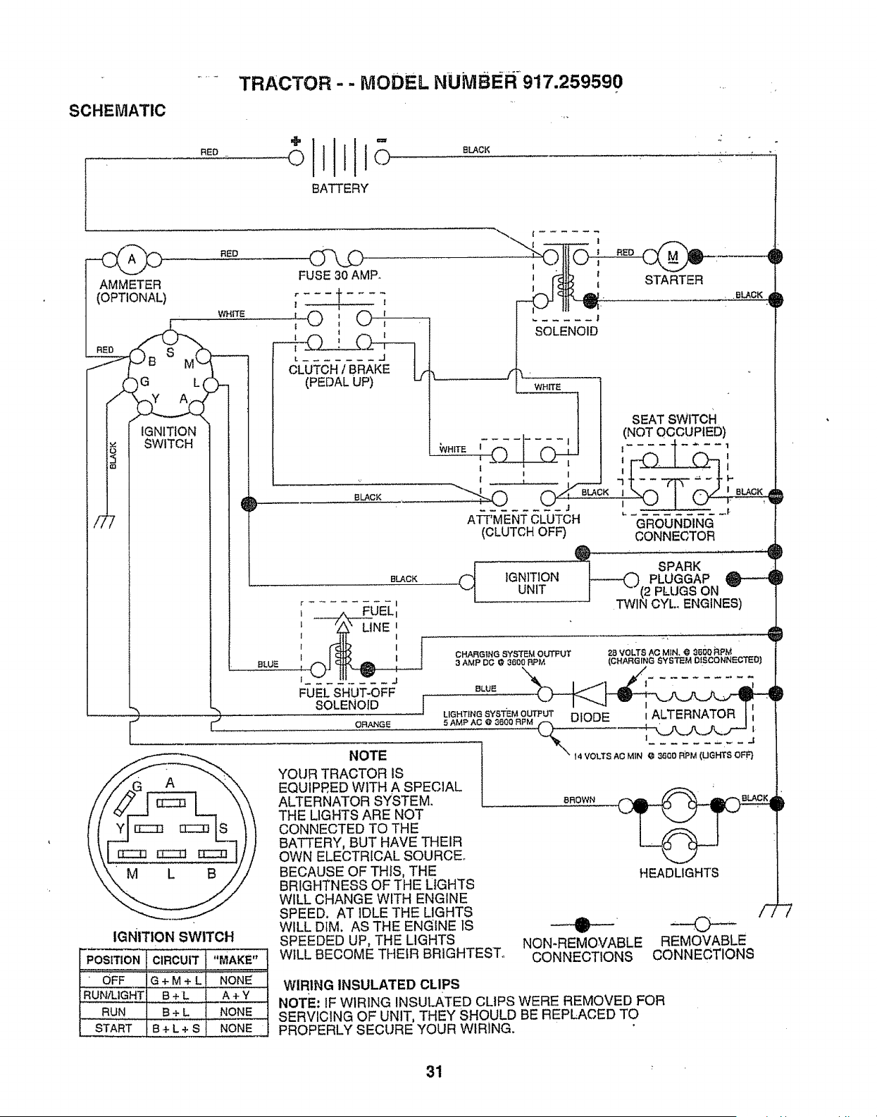
SCHEMATIC
..... TRACTOR - - MODEL NUMBER-917.259590
11t
REO OIIIo 0 oK
BATTERY
FUSE30 AMP.
..... I, .RED
STARTER
L WHITE
| ................ |
:O,O |
(PEDAL UP) u
BLACK
SEATSWrTCH
.... (NOT OCCUPIED)
j I t- ---:'1" .... 1
| _ I ............ I
-'-" "
o#
ATT'MENTCLUTCH GROUNDING
(CLUTCHOFF) CONNECTOR
I _ SPARK .
--_-)INPLUGGAP O---'_D
(2 PLUGS ON
OYL ENGINES)
IGNITION
UNIT
FUEL SHUT-OFF
SOLENOID
CHARGING SYSTEM OUTPUT
3 AMP DG @ 3600 RPM
28 VOLTS AG MIN. @ 88gl} RPM
(CHARGING SYSTEM DISCONNECTED)
IGNITION SWITCH
POSITION CIRCUIT "MAKE"_
.........oF___Q;M,L_,,,,,ONE:
RUN/LIGHT B+L A +Y
_-. RUN B + L NON E
START B+ L + S NONE
BLUE
ORANGE
NOTE
YOUR TRACTOR IS
EQUIPRED WITH A SPECIAL
ALTERNATOR SYSTEM.
THE LIGHTS ARE NOT
CONNECTED TO THE
BATTERY, BUT HAVE THEIR
OWN ELECTRICAL SOURCE.
BECAUSE OF THIS, THE
BRIGHTNESS OF THE LIGHTS
WILL CHANGE WITH ENGINE
SPEED. AT IDLE THE LIGHTS
WILL DIM. AS THE ENGINE IS
BROWN
SPEEDED UP, THE LIGHTS
WILL BECOME THEIR BRIGHTEST.
HEADLIGHTS
NON-REMOVABLE
CONNECTIONS
REMOVABLE
CONNECTIONS
WIRING INSULATED CLIPS
NOTE: IF WIRING INSUU_TED CLIPS WERE REMOVED FOR
SERVICING OF UNIT, THEY SHOULD BE REPLACED TO
PROPERLY SECURE YOUR WIRING.
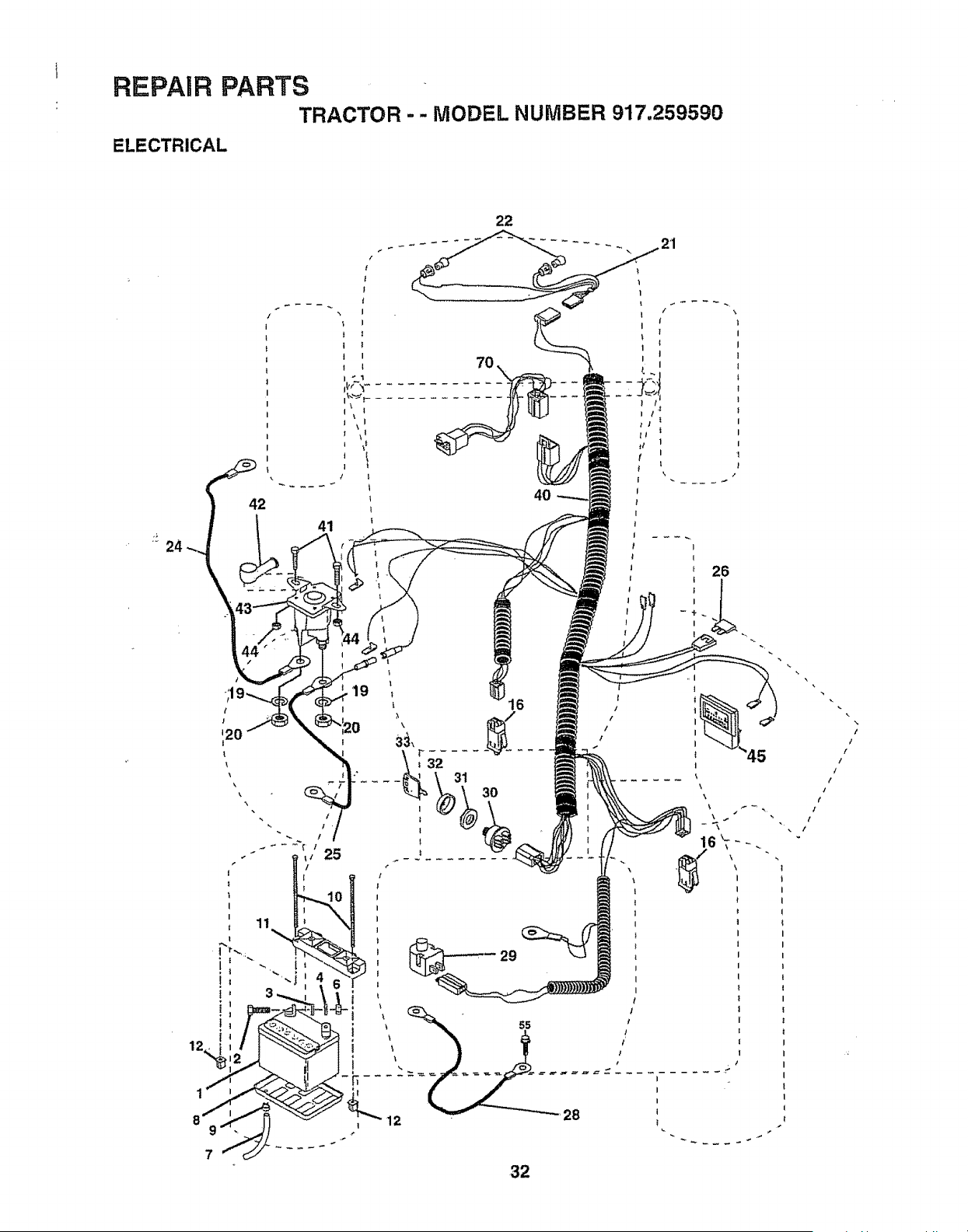
REPAIR PARTS
TRACTOR - - MODEL NUMBER 917.259590
ELECTRICAL
24
22
42
41
7
32
t
/
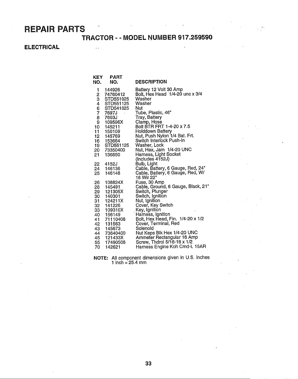
REPAIR PARTS .....
TRACTOR - , MODEL NUMBER 917.259,590
ELECTRICAL ..
KEY PART
NO. NO. DESCRIPTION
1 144926
2 74760412
3 STD551025
4 STD551125
6 STD541025
7 7697J
8 7603J
9 109596X
10 145211
11 15O1O9
i2 145769
16 153664
19 STD551125
20 73350400
21 136850
22 4152J
24 146136
25 146148
26 108824X
28 145491
29 121305X
30 140301
31 1242tIX
32 141226
33 109310X
4O 156149
4't 71110408
42 131563
43 '145673
44 73640400
45 121433X
55 1749O508
70 142621
Battery 12 Volt 30 Amp
Bolt, Hex Head '1/4-20 uric x 3/4
Washer
Washer
Nut
Tube, Plastic, 46"
Tray, Battery
Clamp, Hose
Bolt BTR FRT 1-4-20 x 7,5
Holddown Battery
Nut, Push Nylon 1/4 Bat. Frt.
Switch Interlock Push-In
Washer, Lock
Nut, Hex, Jam 1/4-20 UNC
Harness, Light Socket
(Includes 4152J)
Bulb, Light
Cable, Battery, 6 Gauge, Red, 24"
Cable, Battery, 6 Gauge, Red, W/
16 Wtr 22"
Fuse, 30 Amp
Cable, Ground, 6 Gauge, Black, 2t"
Switch, Plunger
Switch, Ignition
Nut, Ignition
Cover, Key Switch
Key, Ignition
: Harness, Ignition
Bolt, Hex Head, Fin. 1/4-20 x 1/2
Cover, Terminal, Red
Solenoid
Nut Keps BIk Hex 1/4-20 UNC
Ammeter Rectangular 16 Amp
Screw, Thdrol 5/16-18 x 1/2
Harness Engine Koh Cmd-L '15AR
NOTE: All component dimensions given in U.S. inches
1 inch = 25.4 rnm
33
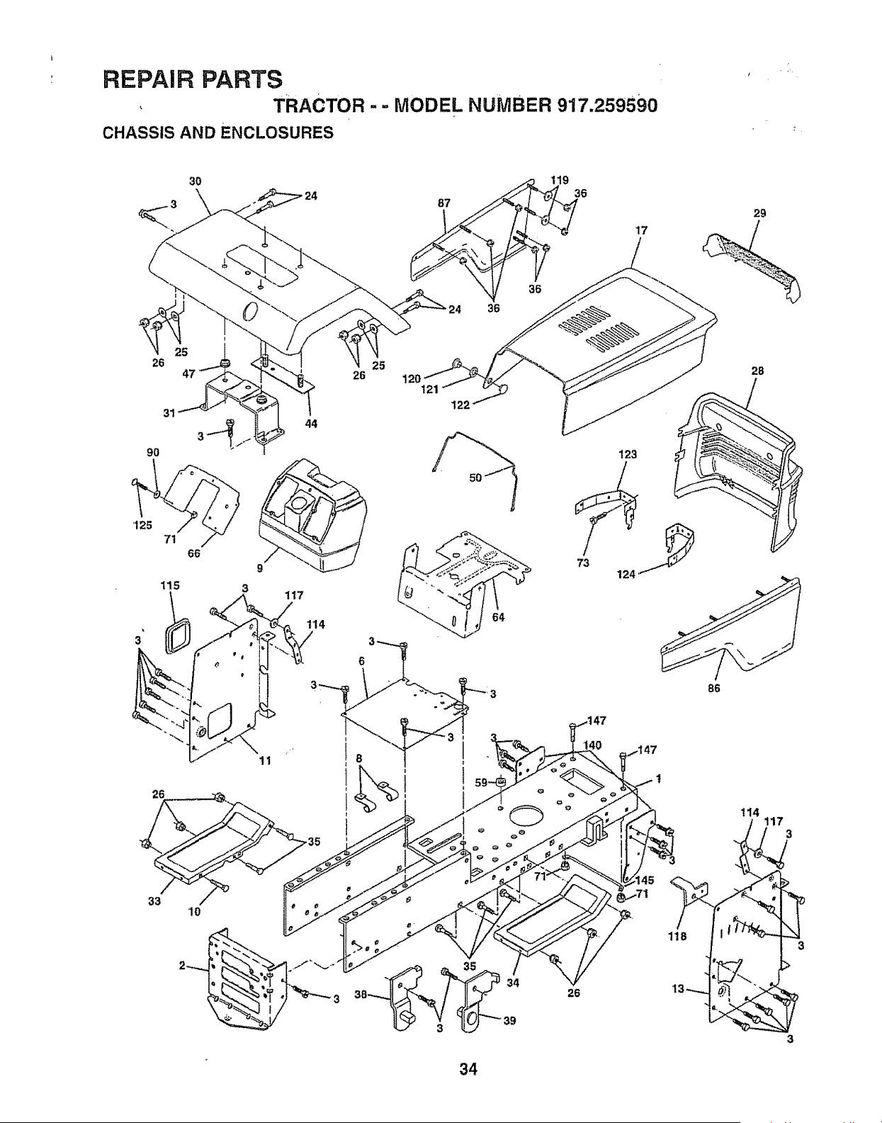
I
REPAIR PARTS
, TRACTOR -- MODEL NUMBER 917.259590
CHASSIS AND ENCLOSURES
3O
\
24
8
36
17
26 25
47 26
31
90
115
3
66
3
44
117
114
t21
123
86
26
33
11
i
i
I
l
i
i
" 34
38
39
26
118
114
3
3
34

REPAIR PARTS
TRACTOR -- MODEL NUMBER 917,259590
CHASSIS AND ENCLOSURES
KEY PART
NO, NO. DESCRIPTION
'1 159530 Chassis
2 140356 Drawbar
3 17490612 Screw, ThdroIo 3/8-16 x 3/4 Type TT
6 155923 Saddle
8 12647!X Clip, Fuel Line
9 145203. Dash, Plastic
10 72140608 Bolt, Carriage 3/8-16x 1
11 145218 Panel, Dash, LH
13 145217 Panel, Dash, RH
17 136673X558 Hood Assembly
24 STD523710 Bolt
25 19131312 Washer 13/32 x 13/16 x 12 Gauge
26 STD541437 Nut
28 136373X428 Grill
29 136374 Lens, Bar, Clear
30 140002X558 Fender
31 137113 Bracket Assembly, Fender
33 I45244X558 Footrest, LH
34 145243X558 Footrest, RH
35 STD533707 Bolt
36 108067X Nut, Pal
38 139886 Bracket Assembly, Pivot, LH
39 139887 Bracket Assembly, Pivot, RH
44 t40675 Fender Strap
47 105531X Nut, Push, Nylon
50 137304 Rod, Support Hood
59 110436X Bushing, Snap, Split
64 150272 Dash, Lower •
66 156276X012 Plate, Dash
7'1 73640400 Nut
73 17580408 Screw Tap Tite 1/4-20 x 1/2
86 136670X558 Panel Assembly, RH
87 136671X558 Panel Assembly, LH
90 STD55t025 Washer 17/64
114 145349 Bracket, Support, Dash
115 121794X Cover, Access
117 144283 Washer Serrated Disk 13/32 x 1
I18 145595 Bracket, Clutch Mech SRS YT 95
119 19092016 Washer 9/32 x !-1/4 x 16 Ga.
I20 137271 Rivet, Ratchet, Female
12'1 137269 Washer, Nylon
122 137270 Rivet, Rachet, Male
123 157105 Bracket Assembly, Pivot, Hood LH
124 157107 Bracket Assembly, Pivot, Hood RH
125 741804'12 Screw, Machine 1/4:20 x 3/4
140 158418 Bracket SuspensionFront
145 !56524 Rod Pivot Chassis/Hood
147 74760412 Bolt, Hex Hd 1/4-20 UNC x 3/4
- - 5479J Ptug, Btn Blk 359 Dia°
NOTE; All component dimensions given _n U.S. inches
1 inch = 25°4 mm
3S
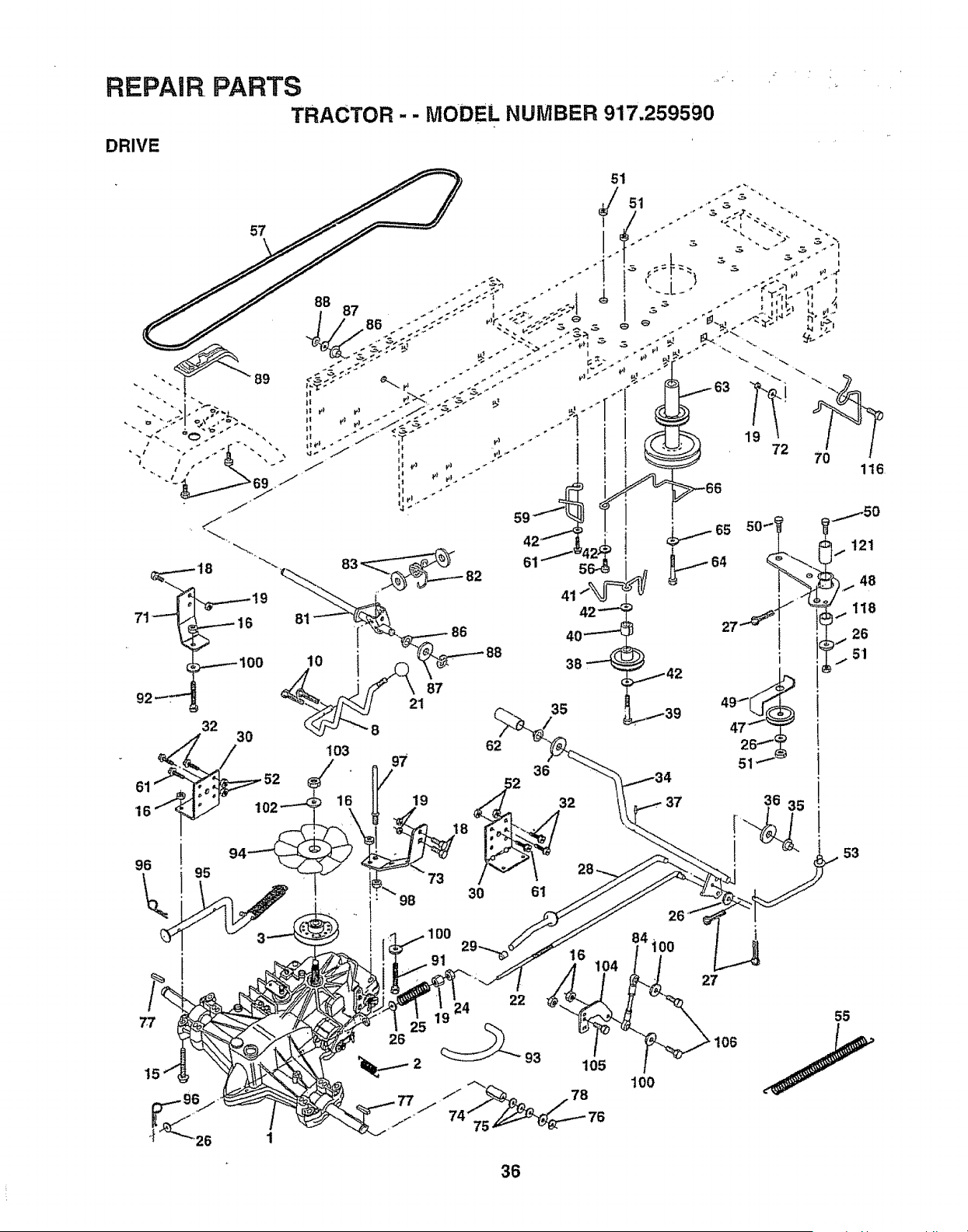
REPA|R pARTS
TRACTOR
DRIVE
.. _oDEL NumBER9'17.259590
51
10
96 95
\
86
87
21 35
62
103 97 36
:"" 98 30
91
22
24
36
100
51
53
O6

REPAIR
DRIVE
PARTS
TRACTOR -- MODEL NUMBER 917,259590
KEY PART
NO. NO.
150071
2 142431
3 143995
8 141002
10 76020416
15 74490544
16 73800500
18 74780616
19 73800600
21 130564
22 145627
24 73350600
25 106888X
26 19131316
27 76020412
28 145204
29 124236X
30 130807
32 74760512
34 155071
35 120183X
36 19211616
37 1572H
38 123674X
39 74760644
40 4470J
4'1 154777
42 19131312
47 127783
48 154604
49 123205X
50 74760624
51 73680600
52 73680500
53 105710X
55 105709X
56 74760620
57 140294
59 140312
61 17490612
62 8883R
KEY PART
DESCRIPTION NO. NO. DESCRIPTION
Transaxle (See Breakdown) Hydro 63
Gr Model 310-0650 64
Spring, Return, Brake 65
Pulley, Transaxle 66
Rod Shift Hydro LT 69
Pin Cotter 1/8 x 1 CAD 70
Bolt Hex Ftghd 5/16-18 Gr:5 71
Nut Lock Hex W/Ins. 5/16-18 Unc 72
Bolt Fin Hex 3/8-!6 Unc x 1 Gr. 5 73
Nut Lock Hex W/Wsh 3/8-16 Unc 74
Knob, Deluxe 1/2-13 75
Rod, Brake Hydro 76
Nut, Hex ,Jam 3/8-16 Uric 77
Spring, Brake Rod 78
Washer 8!
Pin Cotter 1/8 x 3/4 CAD_ 82
Rod, Parking Brake 83
Cap, Parking Brake 84
Bracket, Transaxle 86
Bolt Hex Hd 5/16-18 Unc x 3/4 87
Shaft, Foot Pedal 88
Bearing, Nylon 89
Washer 91
Pin, Roll 92
Pulley, Idler, Flat 93
Bolt 94
Spacer, Split 95
Keeper, Belt Idler 96
Washer 13/32 x 13/16 x 12 Gauge 97
Pulley, Idler, VoGroove 98
Bellcrank Assembly 'I00
Retainer, Belt 102
Bolt 103
Nut Crowntock 3/8-i6 UNC 104
Nut, Crownlock 5/16-18 Unc 105
Link, Clutch 106
Spring, Return, Clutch 116
Bolt Hex 3/8-I6 x 1-1/4 118
V_Bett, Ground Drive 121
Keeper, Center Span
Screw Thdrol. 3/8-16 x 3/4 Tyo TT
Cover, Pedal
140186
71170764
STD551143
154778
142432
134683
140158
19132012
156347
121!99X
121749X
12000001
123583X
121748X
156046
123782X
19171216
14O548
71208
19212016
12000008
I51146
74780536
74780524
142564
t40462
144643
4497H
140469
73510600
19111216
141322
73940800
140156
71O70516
74780520
72110610
154774
154419
Pulley, Engine
Bolt Hex
Washer
Keeper Belt Engine
Screw
Keeper Belt Engine
Strap Torque Lh Hydro 18120"T
Washer 13/32 x 1-1/4x 12 .Gauge
Strap Torque Rh Hydro 18/20" T
Spacer, Split "
Washer 25/32 x 1-1/4 x 16 Gauge
E-Ring
Key, Square
Washer 25/32 x 1-5/8 x 16 Gauge
Shaft Asm. CrosHydro 20" Tires
Spring Torsion
T/A
Washer 17/32 x 3/4 x 16 Ga.
Rod, Tie Hydro 20" Tires
Bushing Rod Strlg. 629/632 ID
Washer 21/32 x 1-1/4 x 16 Ga.
Ring Klip #5304-62
Console, Shift
BoJtFin Hex 5/16-18 x 2_1/4
Bolt Fin Hex 5/6-18 Unc x 1-!/2
Line Fuel Hydro 4"
Fan, Hydro 7"
ControlBypass Hydro 20" Tires
Retainer Spring 1" Zinc/Cad
Keeper Bolt Rh Hydro 0750. 18/20"
Nut Keps Hex 3/8-16 Unc
Washer 11/32 x 3/4 x 16 Ga.
Washer Bellville .501D x 1,50D
Nut Hex Jam Toplock 1/4-20 Unf
Arm, Control Hydro
Screw Cap Hex 5/16 x'18 x 1
Bolt Fin Hex 5/16-18 Unc x 1-1/4
Bolt Rdhd Sq Neck 3/6.16 x 1,25
Spacer Bellcrank
Nyliner Clutching STL
NOTE: All component dimensions given in UoS. inches
1 inch = 25,,4 mm
37

REPAIR PARTS
TRACTOR-- MODEL NUMBER 917,259590
STEERING ASSEMBLY
62
\
\
39
€ €
41
_42
6
40
\
J
48
47
I0
65
68 67
38
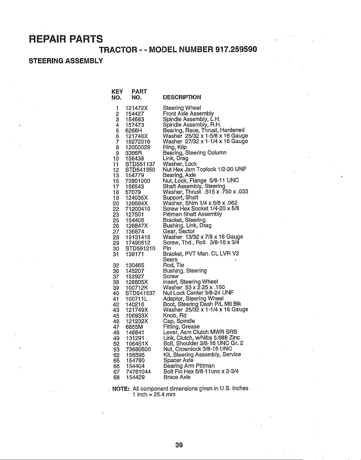
REPAIR PARTS
TRACTOR - - MODEL NUMBER 917.259590
STEERING ASSEMBLY
KEY PART
NO. NO. DESCRIPTION
! 121472X
2 154427
3 154683
4 157473
5 6266H
6 I2t748X
7 19272016
8 12000029
9 3366R
t0 156438
tl STD551137
12 STD541350
13 154779
15 73901000
17 156543
18 57079
19 124035X
20 126684X
22 712OO41O
23 127501
25 154406
26 126847X
27 136874
28 19131416
29 17490612
3O STD561210
31 138171
32 13O465
36 1452O7
37 152927
38 126805X
39 i00712K
40 STD54!537
41 100711L
42 140216
43 121749X
45 106933X
46 121232X
47 6855M
48 146841
49 131291
52 106451X
53 73680600
62 156595
65 154780
66 154404
67 74781044
68 154429
Steering Wheel
Front Axle Assembly
Spindle Assembly, L,H_
Spindle Assembly, Roll.
Bearing, Race, Thrust, Hardened
Washer 25/32 × 1-5/8 x 16 Gauge
Washer 27/32 x 1-t/4 x 16 Gauge
Ring, Klip
Bearing, Steering Column
Link, Drag
Washer, Lock
Nut Hex Jam Topleck 1/2-20 UNF
Bearing, Axle
Nut, Lock, Flange 5/8-1'1 UNC
Shaft Assembly, Steering
Washer, Thrust o515 x ,750 x °033
Support, Shaft
Washer, Shim 1/4 x 5/8 x °062
Screw Hex Socket 1/4-20 x 5/8
Pittman Shaft Assembly
Bracket, Steering
Bushing, Link, Drag
Gear, Sector
Washer 13/32 x 7/8 x 16 Gauge
Screw, Thd., Roll. 3/8-16 x 3/4
Pin
Bracket, PVT Man._CL LVR V2
Sears
Rod, Tie
Bushing, Steering
Screw
Insert, Steering Wheel
Washer 53 x 2,25 x oi60
Nut Lock Center 3/8-24 UNF
Adaptor, Steering Wheel
Boot, Steering Dash P/L Mtl BIk
Washer 25/32 x 1-1/4 x 16 Gauge
Knob, Rd
Cap, Spindle
Fitting, Grease
Lever, Asm Clutch MWR SRS
Link, Clutch, w/Nibs 5.688 Zinc
Bolt, Shoulder 3/8-t6 UNC Gr. 2
Nut, Crownlock 3/8-16 UNC
Kit, Steering Assembly, Service
Spacer Axle
Bearing Arm Pittman
Bolt Fin Hex 5/8-1 lunc x 2-3/4
Brace Axle
NOTE: Art component dimensions given in U,So inches
I inch = 25,.4 mm
39
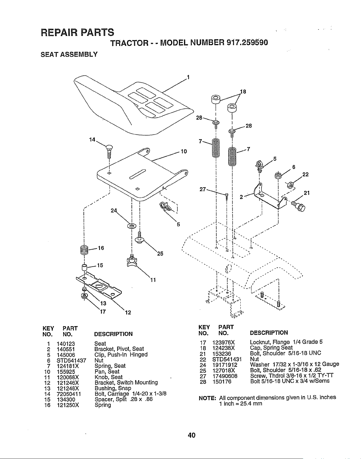
REPAIR PARTS
TRACTOR -- MODEL NUMBER 9t7.2595g0
SEAT ASSEMBLY
KEY PART
NO. NO.
1 140123
2 140551
5 '145006
6 STD541_37
7 124181X
10 155925
tl 120088X
12 121246X
13 121248X
14 72050411
15 134300
'16 121250X
5
11
12
DESCRIPTION
Seat
Bracket, Pivot, Seat
Clip, Push-In Hinged
Nut
Spring, Seat
Pan, Seat
Knob, Seat
Bracket, Switch Mounting
Bushing, Snap
Bolt, Carriage 1/4-20 x 1-3/8
Spacer, Split .28 x .88
Spring
KEY PART
NO. NO. DESCRIPTION
17 123976X
18 124238X
21 153236
22 STD541431
24 19171912
25 127018X
27 17490608
28 150176
Locknut, Flange 1/4 Grade 5
Cap, Spring Seat
Bolt, Shoulder 5/.I6-18 UNC
Nut
Washer 17/32 x 1-3/16 x 12 Gauge
Bolt, Shoulder 5/16-18 x ,62
Screw, Thdrol 3/8-16 x t/2 TY-TT
Bolt 5116-18 UNC x 3/4 w/Seres
NOTE; Atl component dimensions given in U.S° inches
1 inch = 25.4 mm
40
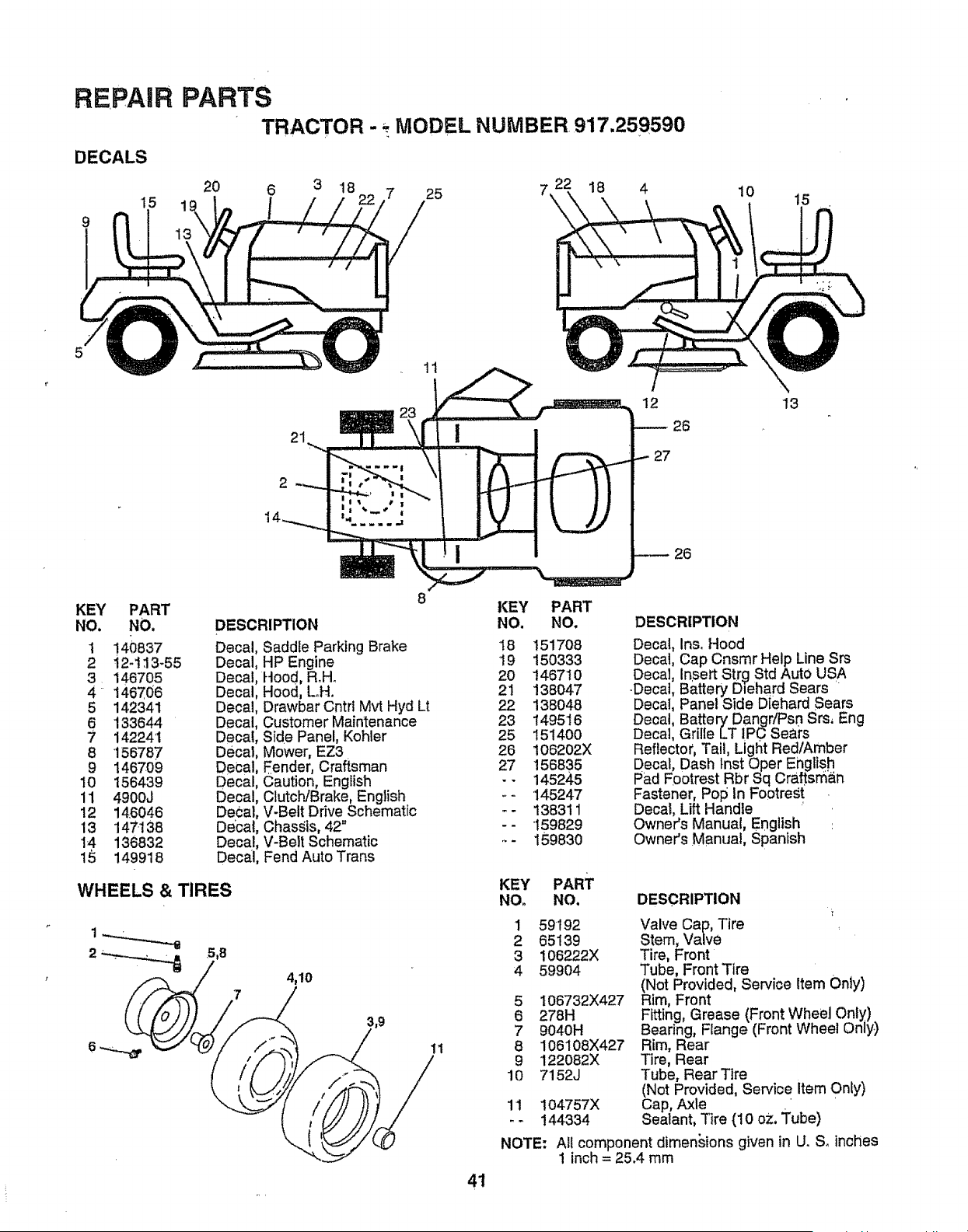
REPAIR
DECALS
I5
9
PARTS
TRACTOR - MODEL NUMBER, 917.259590
20 6 3 18 7 25 7
I
18
21
12
26
27
10
15
13
26
KEY PART
NO. NO.
1 140837
2 i2-113-55
3 146705
4 146706
5 142341
6 133644
7 142241
8 !56787
9 146709
10 156439
11 4900J
12 146046
13 147138
14 136832
15 149918
8
KEY
DESCRIPTION NO.
Decal, Saddle Parking Brake 't8
Decal, HP Engine 19
Decal, Hood, Roll. 20
Decal, Hood, Loll. 21
Decal, Drawbar Cntrl Mvt Hyd Lt 22
Decal, Customer Maintenance 23
Decal, Side Panel, Kohler 25
Decat, Mower, EZ3 26
DeCal, Eender, Craftsman 27
Decal, Caution, English - -
Decal, Clutch/Brake, English - -
Decal, V-Belt Drive Schematic - -
Decal, Chas_;is, 42 ....
Decal, V-Belt Schematic .. -
Decal, Fend Auto Trans
WHEELS & TIRES
,5,B
4,10
11
41
PART
NO.
151708
150333
t467t0
138047
138048
149516
15140O
106202X
156835
145245
145247
138311
"I59829
159830
DESCRIPTION
Decal, Inso Hood
Decal, Cap Cnsmr Help Line Srs
Decal, Insert Str9 Std Auto USA
-Decal, Battery Diehard Sears
Decai, Panel Side Diehard Sears
Decal, Battery DangffPsn Srs, Eng
Decal, GrilleLT IP0 Seai's
Reflector, Tail, Light Red/Amber
Decal, Dash tnst Oper English
Pad Footrest Rbr Sq Craftsman
Fastener, Pop In Footrest
Decal, Lift Handle
Owner's Manual, English
Owner's Manual, Spanish
KEY PART
NO. NO. DESCRIPTION
1 59192
2 65139
3 106222X
4 59904
5
6
7
8
9
10
11
NOTE:
I06732X427
278H
9040H
106108X427
122082X
7152J
104757X
144334
Valve Cap, Tire
Stem, Valve
Tire, Front
Tube, Front Tire
(Not Provided, Service Item Only)
Rim, Front
Fitting, Grease (Front Wheel Only)
Bearing, Flange (Front Wheel Only)
Rim, Rear
Tire, Rear
Tube, Rear Tire
(Not Provided, Sewice Item 0nly)
Cap, Axle
Sealant, Tire (10 oz. Tube)
All component dimen_,ions given in U. S_inches
1 inch= 25.4 mm
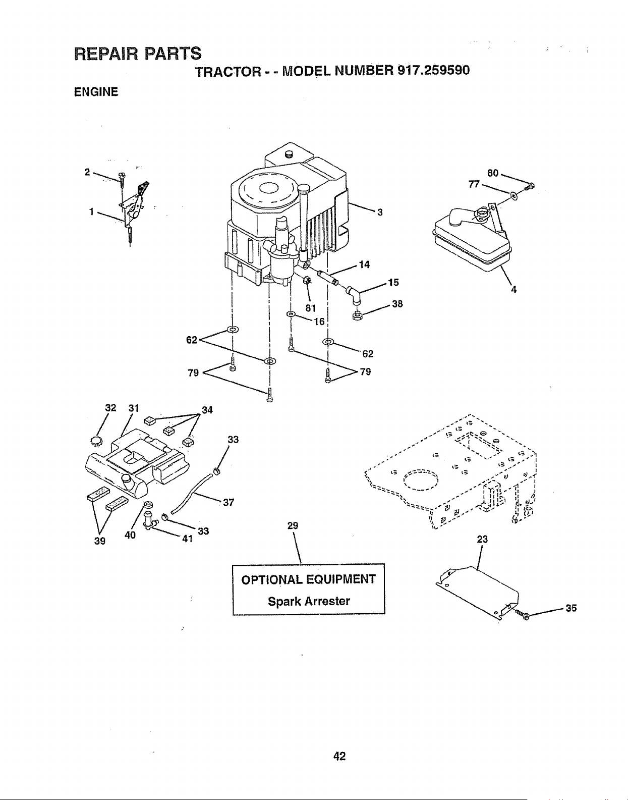
REPAIR PARTS
TRACTOR - - MODEL NUMBER 917.259590
ENGINE
9.•
32 3t
40
39
I
34
6
8O
4
33
29
\
23
OPTIONAL EQUIPMENT
Spark Arrester
35
42
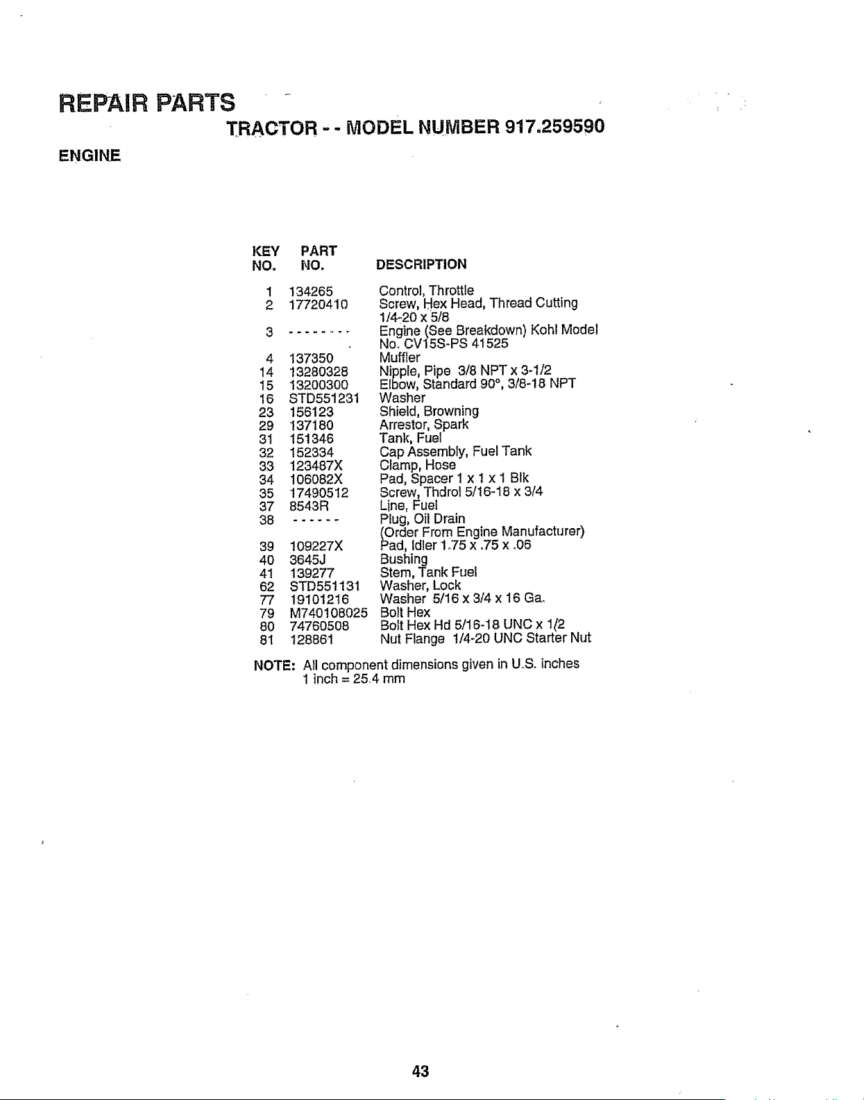
REPAIR PARTS - .,
TRACTOR ,- MODEL NUMBER 917.259590
ENGINE
KEY PART
NO. NO. DESCRIPTION
1 t34265
2 17720410
3
4 137350
14 13280328
I5 13200300
16 STD551231
23 156123
29 137180
3t 151346
32 152334
33 123487X
34 106082X
35 17490512
37 8543R
38 ......
39 109227X
40 3645J
41 139277
62 STD551131
77 191O1216
79 M740108025
80 74760508
81 128861
Control, Throttle
Screw, Hex Head, Thread Cutting
1/4-20 x 5/8
Engine (See Breakdown) Kohi Model
No. CV15S-PS 41525
Muffler
Nipple, Pipe 3/8 NPT x 3-1/2
Elbow, Standard 90 °, 3/8-18 NPT
Washer
Shield, Browning
Arrestor, Spark
Tank, Fuel
Cap Assembly, Fuel Tank
Clamp, Hose
Pad, Spacer I x I x 1 BIk
Screw, Thdrol 5/! 6-18 x 3/4
Line, Fuei
Plug, Oil Drain
(Order From Engine Manufacturer)
Pad, idler 1°75 x .75 x °06
Bushing
Stem, Tank Fuel
Washer, Lock
Washer 5/16 x 3/4 x 16 Ga_
Bolt Hex
Bolt Hex Hd 5/16-18 UNC x 1{t2
Nut Flange 1/4-20 UNC Starter Nut
NOTE: All component dimensions given in U,.S. inches
1 inch = 25,4 mm
43
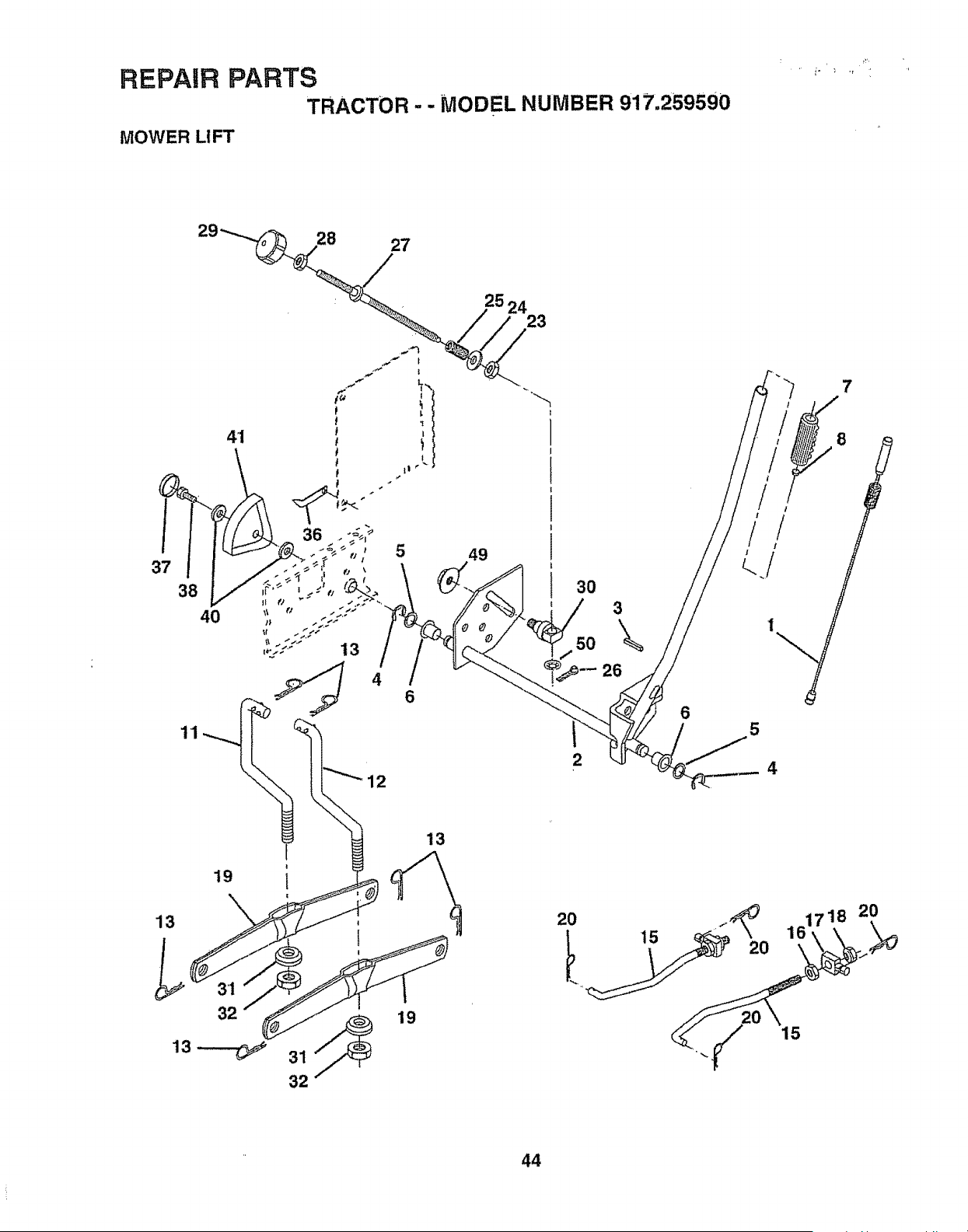
REPAIR PARTS
TRACTOR - - MODEL NUMBER 917.259590
MOWER LIFT
27
4'1
38
40
4
6
12
25 24
23
49
3O
5O
2
3
\
26
6
5
4
19
13
32
I
1
32
19
13
2O
15
44
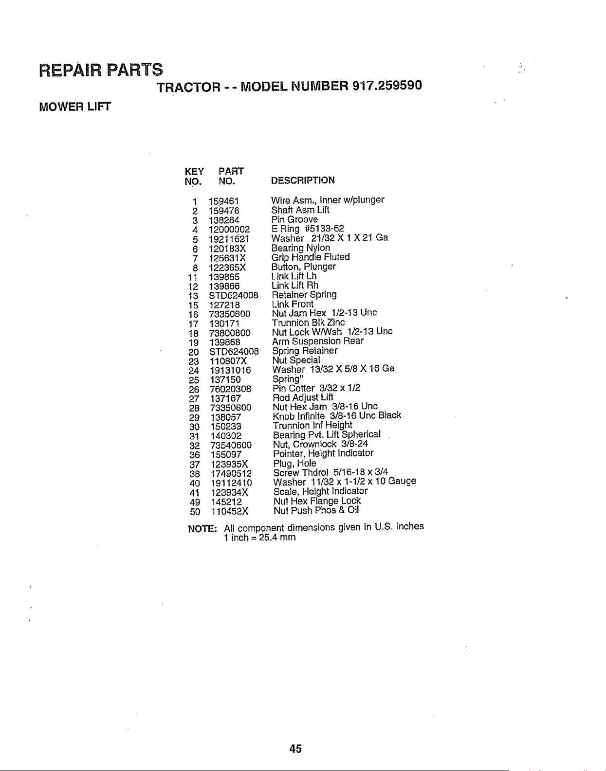
REPAIR PARTS
TRACTOR = - bIODEL NUMBER 917.259590
MOWER LIFT
KEY PART
NO, NO. DESCRIPTION
1 159461
2 159476
3 138284
4 12000002
5 19211621
6 120183X
7 125631X
8 122365X
1t 139865
12 139866
i3 STD624008
15 127218
16 73350800
17 130171
18 7380O800
19 139868
20 STD624008
23 110807X
24 19131O16
25 13715O
26 76020308
27 137167
28 73350600
29 138057
30 150233
31 14O302
32 73540600
36 155097
37 123935X
36 17490512
40 191t2410
41 123934X
49 145212
5O 110452X
NOTE:
Wire Asm., Inner w!plunger
Shaft Asm Lift
Pin Groove
E Ring #5133-62
Washer 21./32 X '1 X 21 Ga
Bearing Nylon
Grip Handte Fluted
Button, Plunger
Link Lift Lh
Link Lift Rh
Retainer Spring
Link Front
Nut Jam Hex 1/2-13 Unc
Trunnion Blk Zinc
Nut Lock W/Wsh 1/2-13 Unc
Arm Suspension Rear
Spring Retainer
Nut Specia!
Washer t3/32 X 5/8 X 16 Ga
Spring"
Pin Cotter &/32 x 1/2
Rod Adjust Lift
Nut Hex Jam 3/8-16 Uric
Knob Infinite 3/8-t6 Uric Black
Trunnion Inf Height
Bearing Pvt. Lift Spherical
Nut, Crownfock 3/8-24
Pointer, Height indicator
Plug, Hole
Screw Thdro] 5/16-18 x 3/4
Washer 11/32 x 1-1/2 x 10 Gauge
Scale, Height Indicator
Nut Hex Ftange Lock
Nut Push Phos & Oil
All component dimensions given in U.S. inches
t inch = 25.4 mm
45

i
REPAIR PARTS
TRACTOR - - MODEL NUMBER 917.259590
MOWER DECK
76
52
34
.33
32
31
102
101
'_"104
105 _
106
105
106
\
2
16
29
27
46
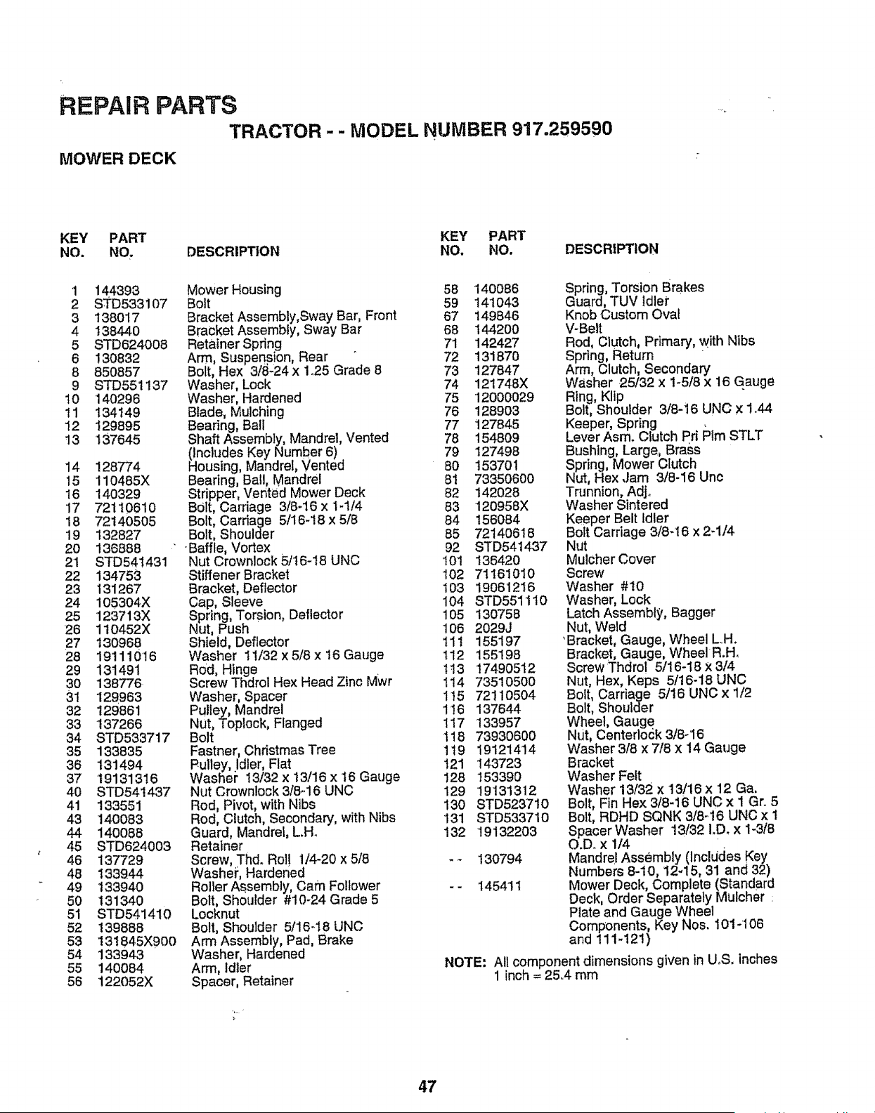
REPAIR PARTS
TRACTOR - - MODEL NUMBER 917.259590
MOWER DECK
KEY PART KEY PART
NO. NO. DESCRIPTION NO. NO. DESCRIPTION
1 144393
2 STD533107
3 138017
4 138440
5 STD624008
6 130832
8 850857
9 STD551137
10 140296
11 134149
12 129895
t3 137645
14 128774
15 "110485X
16 140329
17 72110610
18 72140505
19 132827
20 136888 "
21 STD541431
22 134753
23 131267
24 105304X
25 '123713X
26 110452X
27 130968
28 191110'16
29 131491
30 138776
31 129963
32 129861
33 137266
34 STD533717
35 133835
36 131494
37 19131316
40 STD541437
41 133551
43 140083
44 140088
45 STD624003
46 137729
48 133944
49 t33940
50 131340
51 STD541410
52 139888
53 131845X900
54 133943
55 140084
56 122052X
Mower Housing 58
Bolt 59
Bracket Assembly,Sway Bar, Front 67
Bracket Assemb y, Sway Bar 68
Retainer Spring 71
Arm, Suspension, Rear ° 72
Bolt, Hex 3/_1-24x 1.25 Grade 8 73
Washer, Lock 74
Washer, Hardened 75
Blade, Mulching 76
Bearing, Ball 77
Shaft Assembly, Mandrel, Vented 78
(includes Key Number 6) 79
Housing, Mandrel, Vented 80
Bearing, Bail, Mandrel 81
Stripper, Vented Mower Deck 82
B01t,Cardage 3/8-16 x 1-114 83
Bolt, Cardage 5/18-18 x 5/8 84
Bolt, Shoulder 85
-Baffle, Vortex 92
Nut Crownlock 5/16-18 UNC '!01
Stiffener Bracket 102
Bracket, Deflector 103
Cap, Sleeve 104
Spring, Torsion, Deflector 105
Nut, Push 106
Shield, Deflector tl t
Washer 11/32 x 5/8x 16 Gauge 112
Rod, Hinge 1t3
Screw Thdrol Hex Head Zinc Mwr 114
Washer, Spacer 1t5
Pulley, Mandre 116
Nut, Toplock, Flanged 117
Bolt 118
Fastner, Christmas Tree 1t9
Pulley, Idler, Flat t21
Washer I3/32 x 13/16 x t6 Gauge 128
Nut Crownlock 3/8-16 UNC 129
Rod, Pivot, with Nibs 130
Rod, Clutch, Secondary, with Nibs '131
Guard, Mandrel, L.H_ 132
Retainer
Screw, Th& Rol! 1/4-20 x 5/8 - -
Washei _,Hardened
Roller Assembly, Cam Follower - -
Bolt, Shoulder #10-24 Grade 5
Locknut
Bolt, Shoulder 5/18-18 UNC
Arm Assembly, Pad, Brake
Washer, Hardened
Arm, Idler
Spacer, Retainer
140086
141043
149846
144200
142427
131870
127847
121748X
12000029
128903
127845
154809
127498
1537O1
73350600
142028
120958X
156084
72140618
STD541437
136420
7t 161010
19061216
STD5511 t0
130758
2029J
155197
155198
17490512
73510500
72110504
137644
133957
73930600
19121414
143723
153390
'19131312
STD523710
STD533710
19132203
130794
145411
Spring, Torsion Brakes
Guard, TUV td er
Knob Custom Oval
V-Belt
Rod, Clutch, Primary, with Nlbs
Spring, Retum
Arm, Clutch, Secondary
Washer 25/32 x 1-5/8 x t6 Gauge
Ring, Kltp
Bolt, Shoulder 3/8-16 UNC x 1o44
Keeper, Spring
Lever Asm. Clutch Pd PIm STLT
Bushing, Large, Brass
Spring, Mower C[utch
Nut, Hex ,Jam 3/8-16 Unc
Trunnion, Adjo
Washer Sintered
Keeper Belt Idler
BoIt Carriage 3/8-16 x 2-1/4
NUt
Mulcher Cover
Screw
Washer #10
Washer, Lock
Latch Assembly, Bagger
Nut, Weld
'Bracket, Gauge, Wheel L..H.
Bracket, Gauge, Wheel R,Ho
Screw Thdrol 5/16-18 X3/4
Nut, Hex, Keps 5/16-18 UNC
Bolt, Carriage 5/16 UNC x 1/2
Bolt, Shoulder
Wheel, Gauge
NUt, Centerlock 3/8-16
Washer 3/8 x 7/8 x 14 Gauge
Bracket
Washer Felt
Washer 13/32 x 13/16 x 12 Ga.
Bolt, Fin Hex 3/8-16 UNC x 1 Gr. 5
Bolt, RDHD SQNK 3/8-16 UNC x 1
Spacer Washer 13/32 I.Dox 1-3/8
O.D.x 1/4
Mandrel Assembly (InclUdes Key
Numbers 8-10, 12 15, 31 and 32)
Mower Deck, Complete (Standard
Deck, Order Separately Mulcher :
Plate and Gauge Wheel
Components, Key Nos. 101-106
and 111-121)
NOTE: All component dimensions given in U_S. inches
1 inch = 25..4 mm
47
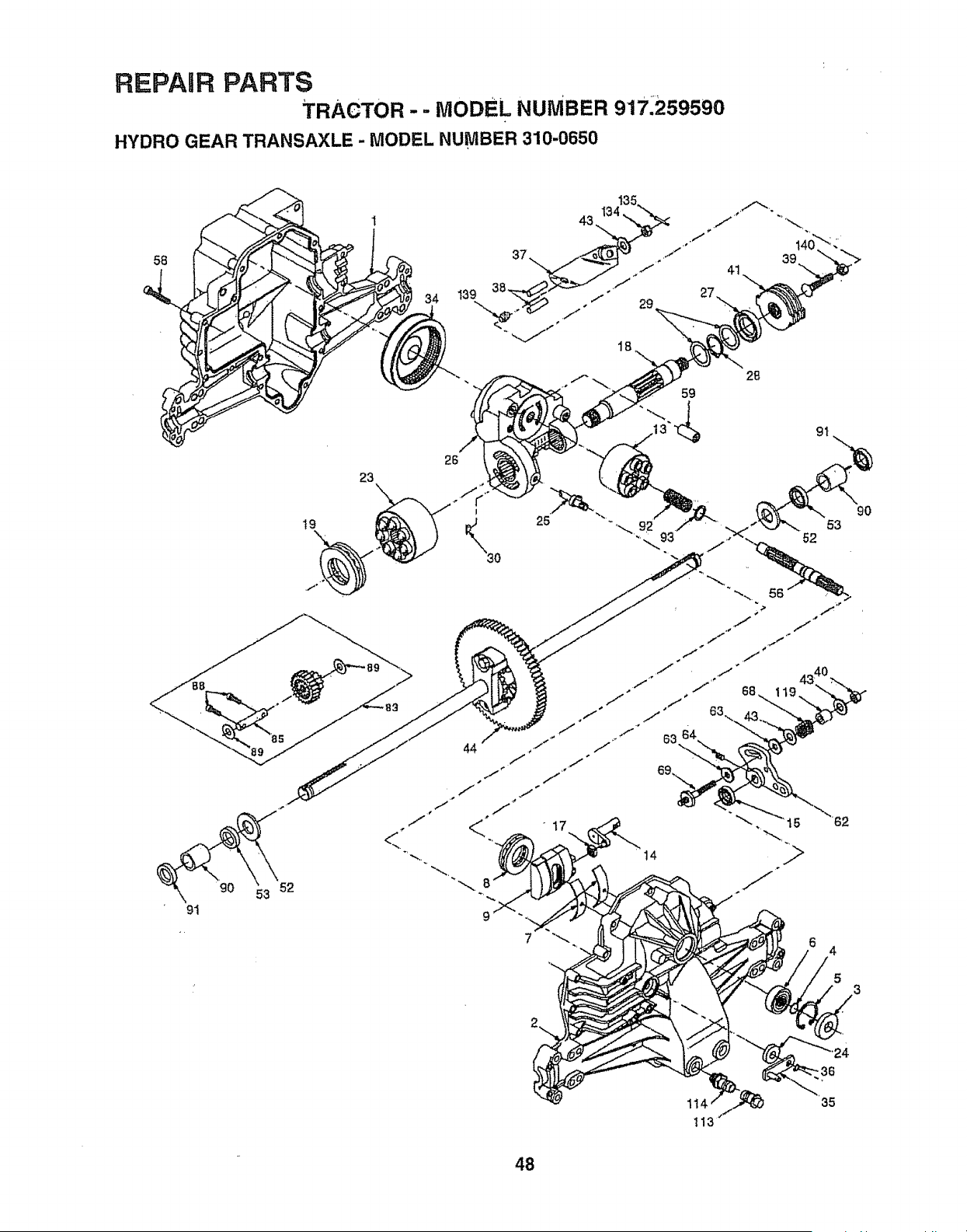
REPAIR PARTS
TRACTOR -- MODEL NUMBER 917,259590
HYDRO GEAR TRANSAXLE - MODEL NUMBER 310-0650
58
90
91
52
23
\
t9
34
37
26
28
4
5
3
1t4
t13
35
48
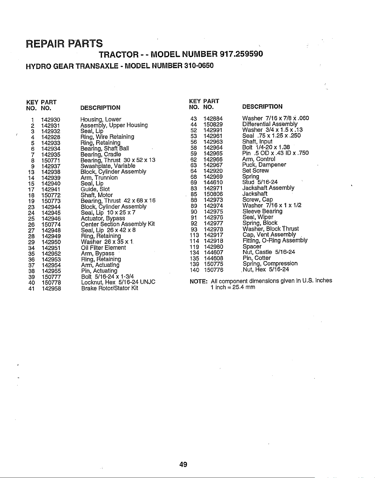
REPAIR PARTS
TRACTOR - - MODEL NUMBER 917.259590
HYDRO GEAR TRANSAXLE - MODEL NUMBER 310-0650
KEY PART KEY PART
NO. NO. DESCRIPTION NO. NO. DESCRIPTION
1 142930 Housing, Lower 43 142884 Washer 7/'16 x 7/8 X .060
2 142931 Assembly, Upper Housing 44 150829 Differential Assembly
3 142932 Seal, Lip 52 142991 Washer 3/4 x 1.5 x.13
4 142928 Ring, Wire Retaining 53 142961 Seal °75 x 1o25 x .250
5 142933 Ring, Retaining 56 142963 Shaft, Input
6 142934 Bearing, Shaft Ball 58 142964 Bolt 1/4-20 x 1.38
7 142935 Bearing, Cradle 59 142965 Pin .50D x .43 ID x .750
8 150771 Bearing, Thrust 30 x 52 x 13 62 142966 Arm, Control
9 142937 Swashplate, Variable 63 142967 Puck, Dampener
13 142938 Block, Cylinder Assembly 64 t42920 Set Screw
14 142939 Arm, Trunnion 68 142969 Spring
15 142940 Seat, Lip 69 144610 Stud 5/t6-24
17 142941 Guide, Slot 83 142971 JackshaftAssembly
18 150772 Shaft, Motor 85 150806 Jackshaft
19 150773 Bearing, Thrust 42 x 68 x 16 88 142973 Screw, Cap
23 142944 Block, Cylinder Assembly 89 142974 Washer 7/16 x I x 1/2
24 142945 Seal, Lip 10 x 25 x 7 90 142975 Sleeve Bearing
25 142946 Actuator, Bypass 91 142976 Seal, Wiper
26 150774 Center Section Assembly Kit 92 t42977 Spring, Block =.
27 142948 Seal, Lip 26 x 42 x 8 93 142978 Washer, Block Thrust
28 142949 Ring, Retaining 113 142917 Cap, Vent Assembly .
29 142950 Washer 26 x 35 x 1. 114 142918 Fitting, O-R ng Assembly
34 142951 Oil Filter Element 1t9 '142980 Spacer
35 142952 Arm, Bypass ' 134 144607 Nut, Castle 5/16-24
36 142953 Ring, Retaining 135 144608 Pin, Cotter
37 142954 Arm, Actuating 139 150775 Spring, Compression
38 142955 Pin, Actuating 140 150776 .Nut, Hex 5/16-24
39 150777 Bolt 5/16-24 x 1-3/4
40 150778 Locknut, Hex 5/16-24 UNJC NOTE: All component dimensions given in UoS.inches
41 142958 Brake Rotor/Stator Kit 1 inch = 25_4 mm
49
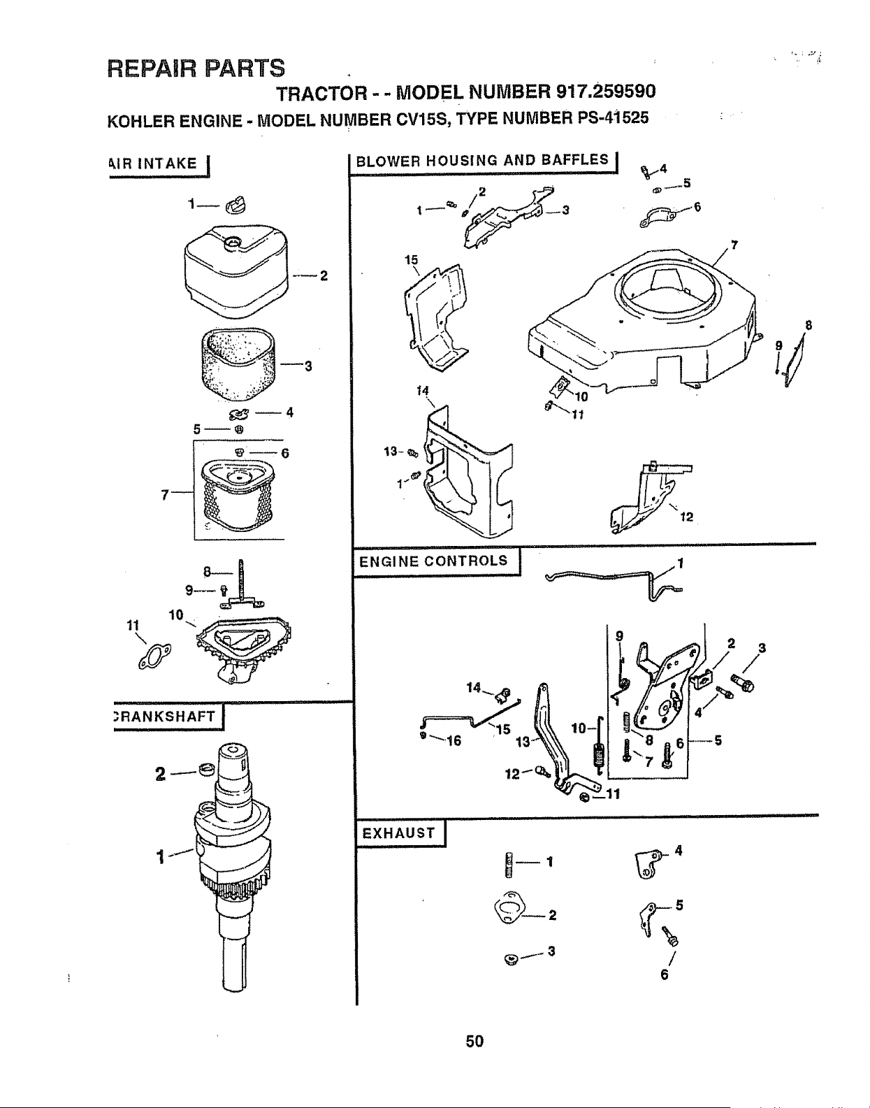
REPAIR PARTS
TRACTOR - - MODEL NUMBER 917.259590
KOHLER ENGINE - MODEL NUMBER CV15S, TYPE NUMBER PS-4i525
_!.R INTAKE !
10,.
11
\
.?,RANKSHAFT ! .........
I I I IILI III iii1,1
BLOWER HOUSING AND BAFFLES I
t5
_5
H
13- _ __"_
I_'__,
ENGINE C"0NTROLS ! " ........ 1
o'_t6
/
6
EXHAUSTI
3
/
8
50
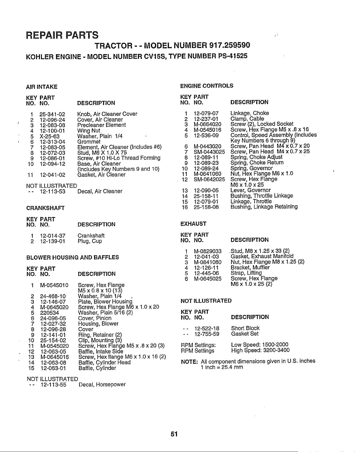
REPAIR PARTS
TRACTOR - - IVIODEL NUMBER 917,259590
KOHLER ENGINE - MODEL NUMBER CVtSS, TYPE NUMBER PS-41525
AIR INTAKE
ENGINE CONTROLS
KEY PART KEY PART
NOo NO. DESCRIPTION NO. NO.
I 25-34!-02
2 12-096-24
3 12_083-08
4 12-100-01
5 X-25_63
6 12-313-04
7 12_083-05
8 12-072-03
9 12-086-01
10 12_094-12
Knob, Air Cleaner Cover
Cover, Atr Cleaner
Precleaner Element
Wing Nut
Washer, Plain t/4
Grommet
Element, Air Cleaner (includes #6)
Stud, M6 X 1.0 X 75
Screw, #10 Hi-Lo Thread Forming
Base, Air Cleaner
('Includes Key Numbers 9 and 10)
Gasket, Air Cleaner
11 12-041-02
NOT ILLUSTRATED
- - t2_! 13-53 Decal, Air Cleaner
DESCRIPTION
Crankshaft
Plug, Cup
CRANKSHAFT
KEY PART
NO. NO.
1 12-014-37
2 12-139-01
BLOWER HOUSING AND BAFFLES
KEY PART
NO. NO. DESCRIPTION
M-0545010
2 24-468-10
3 12-146-07
4 M-0645020
5 220534
6 24-096-05
7 12-027:32
8 12-096-28
9 12-141-01
10 25-154_02
11 M-0545020
12 12-063-05
13 M-0645016
14 12-063-08
15 12-063-01
Screw, Hex Flange
M5 x 0.8 x 10 {13)
Washer, PIain 1/4
Plate, Blower Housing
Screw, Hex Flange M6 x 1o0x 20
Washer, Plain 5/I6 (2)
Cover, Pinion
Housing, Blower
Cover
Ring, Retalner (2)
Clip, Mounting (3)
Screw, Hex Flange M5 x .8 x 20 (3)
Baffle, Intake Side
Screw, Hex flange M6 x 1o0x 16 (2)
Baffle, Cylinder Head
Baffle, Cylinder
iLLUSTRATED
12-113-55 DecaI, Homepower
NOT
DESCRIPTION
1 12-079-07
2 12-237-01
3 M-0664020
4 M-0545016
5 12-536-09
6 M-0443020
7 SM°0443025
8 12-089-11
9 12-089-23
I0 12-089-24
11 M-0641060
!2 SM-0642025
13 12-090-05
i4 25-158-11
15 12-079-0I
16 25_158-08
Linkage, Choke
Clamp, Cable
Screw (2), Locked Socket
Screw, Hex Flange M5 x .8 x 16
Control, Speed Assembly(Includes
Key Numbers 6 through 9)
Screw, Pan Head M4 x 0.7 x 20
Screw, Pan Head M4 x 0.7 ×.25
Spdng, Choke Adjust
Spring, Choke Return
Spring, Governor '
Nut, Hex Flange M6 x 1,0
Screw, Hex Flange
M6 x 1.0 x 25
Lever, Governor
Bushing, Throttle Linkage
Linkage, Throttle
Bush ng, Linkage Retaining
EXHAUST
KEY PART
NO. NO.
1 M-0829033
2 12-041-03
3 M-0841080
4 12_126-11
5 12-445-06
6 M-0645025
DESCRIPTION
.Stud, M8 x 1o25 x 33 12)
Gasket, Exhaust Manifold
Nut, Hex Flange M8 x t.o25 (2)
Bracket, Muffler
Strap, Lifting
Screw, Hex Flange
M6 x 1,0 x 25 (2)
NOT ILLUSTRATED
KEY PART
NO, NO.
-- !2-522-18
-- 12-755-59
RPM Settings:
RPM Settings
DESCRIPTION
Short Block
Gasket Set
Low Speed: i500-2000
High Speed: 3200-3400
NOTE: All component dimensions given in U,& inches
1 inch = 25°4 mm
51
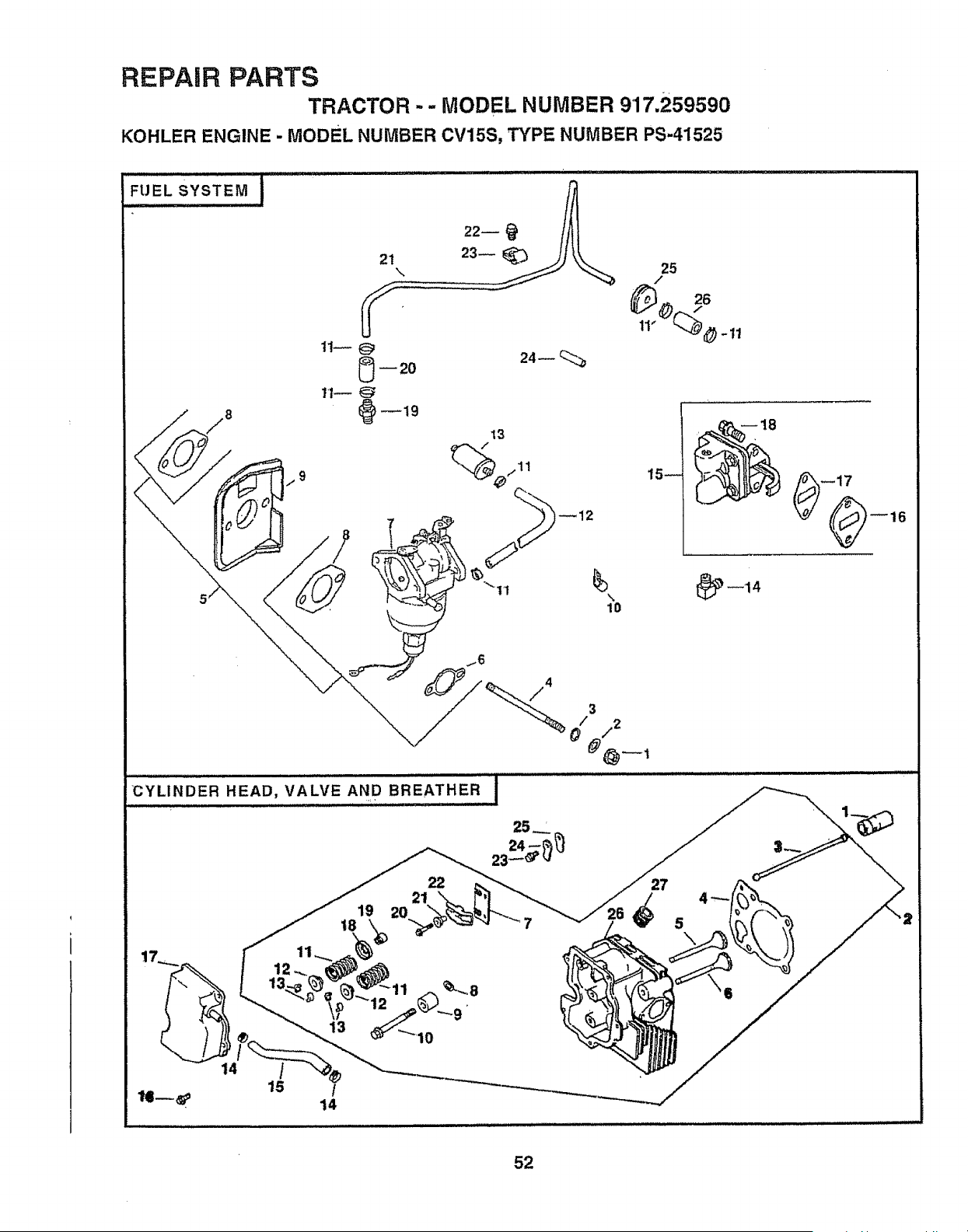
REPAIR PARTS
TRACTOR -- MODEL NUMBER 917.259590
KOHLER ENGINE - MODEL NUMBER CV15S, TYPE NUMBER PS-41525
"'FUEL SYSTEM I
\
1!-- @
_ 20
24_ _
25
15_
CYLINDER HEAD, VALVE AND BREATHER'"I
19 20
18
22
21
10
/4
3
0/^/2
5
\
52
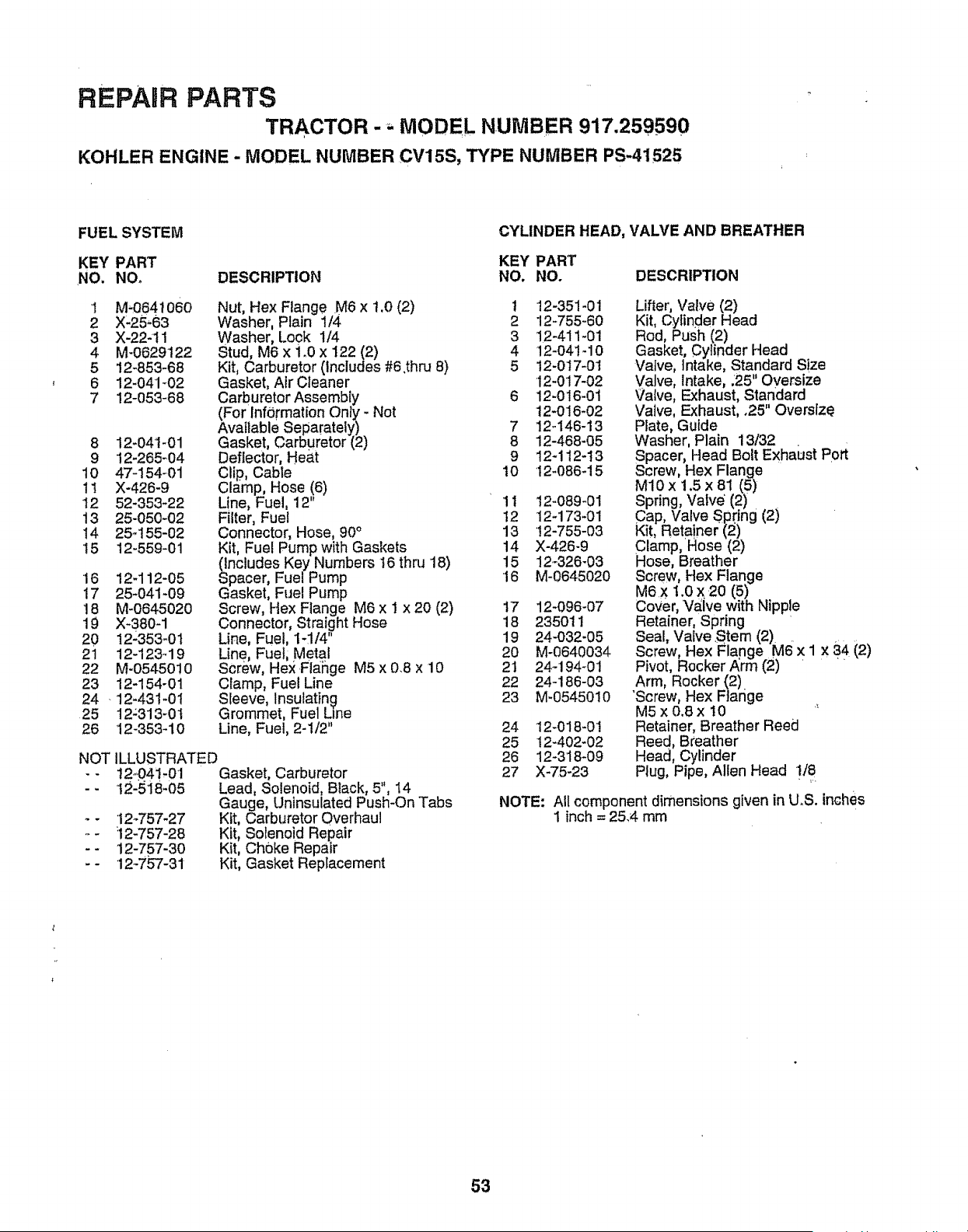
REPAIR PARTS
TRACTOR -,. MODEL NUMBER 917.259590
KOHLER ENGINE - MODEL NUMBER CV15S, TYPE NUMBER PS-41525
FUEL SYSTEM
CYLINDER HEAD, VALVE AND BREATHER
KEY PART KEY PART
NO. NOo DESCRIPTION NO. NO. DESCRIPTION
'I M-0641060
2 X-25,63
3 X-22-11
4 M-0629122
5 12-853-68
6 12-041-02
7 12-053-68
8 12-041-01
9 12-265-04
10 47-154-01
11 X-426-9
12 52-353-22
13 25-050-02
I4 25_t55-02
15 12-559-01
Nut, Hex Flange M6 x t.0 (2) t
Washer, Plain 1/4 2
Washer, Look 1/4 3
Stud, M6 x 1_0x 122 (2) 4
Kit, Carburetor (Includes #6.thru 8) 5
Gasket, Air Cleaner
Carburetor Assembly 6
(For Information Only - Not
Available Separately) 7
Gasket, Carburetor (2) 8
Deflector, Heat 9
Clip, Cable 10
Clamp, Hose (6)
Line, Fuel, 12" 11
Filter, Fuel 12
Connector, Hose, 90° 13
Kit, Fuel Pump with Gaskets 14
(includes Key Numbers t6 thru 18) 15
Spacer, Fuel Pump 16
Gasket, Fuel Pump
Screw, Hex Flange M6 x 1 x 20 (2) 17
Connector, Straight Hose 18
Line, Fuel, 1-1/4" 19
Line, Fuel, Metal 20
Screw, Hex .Fla_hgeM5 x 0.8 x 10 21
Clamp, Fuel Line 22
Sleeve, Insulating 23
Grommet, Fuel Line
Line, Fuel, 2-1/2"
•16 12-112-05
17 25-041-09
18 M-0645020
19 X-380-1
20 12-353-01
21 12-123-19
22 M-0545010
23 12-154-01
24 . 12-43!-01
25 12;313-0I
26 12-353-10
NOT LLUSTRATED
- - t2_04t-01
-- t2-5i8-05
12_757-27
12-757-28
12-757-30
12-75"7-31
Gasket, Carburetor
Lead, Solenoid, Black, 5", 14
Gauge, Untnsulated Push-On Tabs
Kit, Carburetor Overhaul
Kit, Solenoid Repair
Kit, Choke Repair
Kit, Gasket Replacement
w.
12-351-01
12_755-60
12-411-01
12-04t-10
12-0t7-0t
12-0'17-02
12-016-01
12-016-02
12..146-13
12-468-05
12-112-13
12-086-15
!2-089-01
t 2-173-01
'!2-755-03
X-426-9
12_326-03
M-0645020
12-096-07
235011
24-032-05
M-0640034
24-194-01
24-186-03
M-0545010
24 12-018-O!
25 t2-402-02
26 12-318-09
27 X-75-23
Lifter, Valve (2)
Kit, Cylinder Head
Rod, Push (2)
Gasket, Cylinder Head
Valve, Intake, Standard Size
Valve, Intake, .25" Oversize
Valve, Exhaust, standard
Valve, Exhaust, .25" Oversize
Plate, Guide
Washer, Plain 13/32
Spacer, Head Bolt Exhaust Port
Screw, Hex Flange
M10 x 1.5 x 81 (5)
Spring, Valve' (2)
Cap, Valve Spring (2)
Kit, Reta!ner (2)
Clamp, Hose (2)
Hose, Breather
Screw, Hex Flange
M6 X 1.0 X 20 (5)
Cover, Valve with Nipp!e
Retainer, Spring
Seal, Valve .Stem (2)
Screw, Hex Flange M6 x 1 x 84 (2)
Pivot, Rocker,_rm (2) '
Arm, Rocker (2)
'Screw, Hex Flange
M5 x 0o8x 10 _
Retainer, Breather Reed
Reed, Breather
Head, Cylinder
Plug, Pipe, Allen Head t/8
NOTE: All component dimensions given in U.S. inches
1 inch = 25.4 mm
53
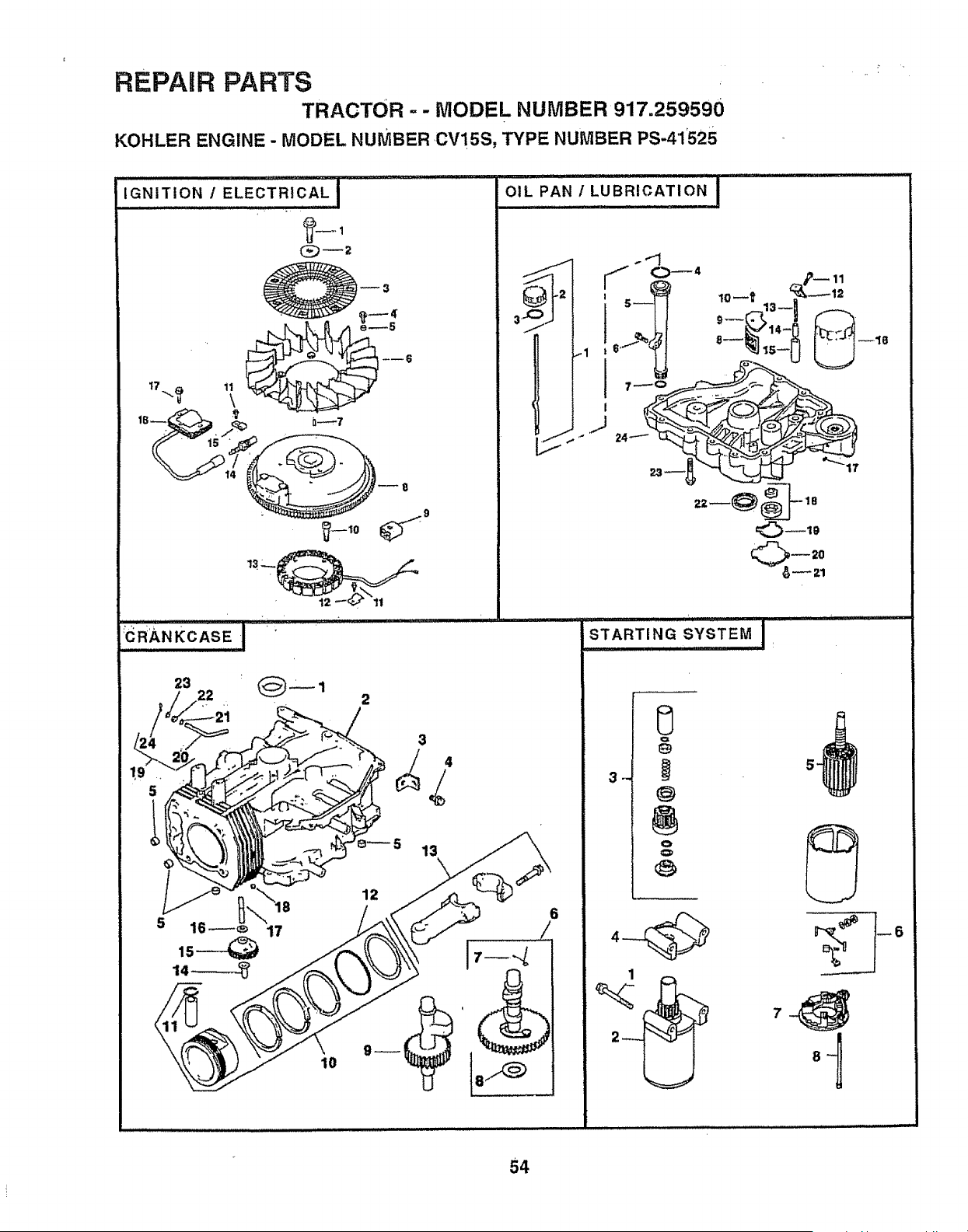
REPAIR PARTS
TRACTOR - - MODEL NUMBER 917.259590
KOHLER ENGINE - MODEL NUMBER CV!5S, TYPE NUMBER PS-41525
IGNITION /ELEcTRIcAL I
+
17 _ 11
to
: .......... i I LI iii ii J,,i i
OIL PAN / LUBRICATION I
J
0_4
_J
6
I1"'l"""u'1 i ' _ ii ill
STARTING ,SYSTEM ,
1
2
.
54
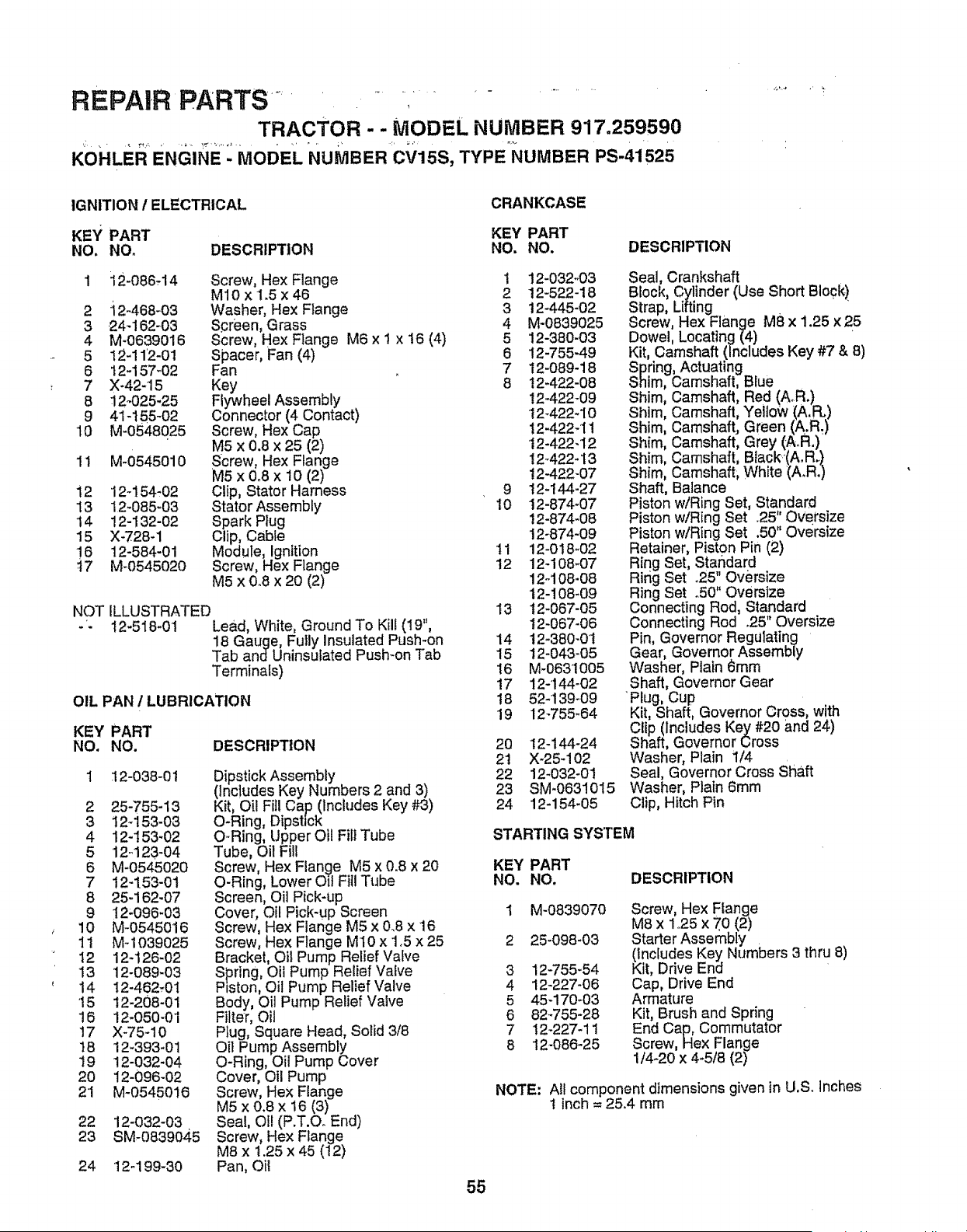
REPAIR PARTS" .... ,.........
TRACTOR - - MODEL NUMBER 917.259590
KOHLER ENGINE- MODEL NUMBER CV15S, TYPE"_IUMBER PS-41525
IGNITION / ELECTRICAL
CRANKCASE
KEY PART KEY PART
NO, NO. DESCRIPTION NO. NO, DESCRIPTION
1 i 2-086-14 Screw, Hex Flange 1 12-032-03
M10 x 1.5 x46 2 12-522-18
2 i2-468-03 Washer, Hex Flange 3 12-445-02
3 24-162-03 Spreen, Grass 4 M-0839025
4 M-0639016 Screw, Hex Flange M6 x I x 16 (4) 5 12-380-03
5 12-112-01 Spacer, Fan (4) 6 12-755-49
6 12-157-02 Fan 7 12-089-18
7 X-.42-15 Key 8 12-422-08
8 i2-025-25 Flywheel Assembly !2-422-09
9 41-155-02 Connector (4 Contact) 12-422-10
10 M-0548025 Screw, Hex Cap 12-422-I1
M5 x 0.8 x 25 (2) 12-422-12
11 M-0545010 Screw, Hex Flange 12-422-13
M5 x 0.8 x 10 (2) !2-422-07
12 12-154-02 Clip, Stator Harness 9 12-t44-27
13 12-085-03 Stator Assembly 10 12-874-07
14 12-132-02 Spark Plug 12-874-08
15 X-728,1 Clip, Cable 12-874-09
!6 12-584-01 Module, Ignition 11 12-018_02
i7 M_0545020 Screw, Hex Flange 12 12-108_07
M5 x 0.8 x 20 (2) 12-108-08
t2-108-09
NOT ILLUSTRATED 13 12-067-05
- - 12-518-01 Lead, White, Ground To Kill (19", t2-067-06
18 Gauge, Fully Insulated Push-on 14 12-380-0t
Tab and Uninsutated Push-on Tab 15 12-043-05
Terminals) 16 M-0631005
17 12-144-02
OIL PAN I LUBRICATION 18 52-139-09
19 12-755-64
KEY PART
NO. NO. DESCRIPTION
:12-038-0 t
2 25-755-13
3 I2_153-03
4 12-153-02
5 '12..123-04
6 M-0545020
7 12-153-01
8 25-162-07
9 !2"096"03
10 M-0545016
1t M-1039025
12 12-126-02
13 12-089-03
14 12-462-01
15 12-208-01
16 12-050-01
17 X-75-10
!8 12-393-01
19 12-032-04
20 12-096-02
2'I M-0545016
22 12-032-03
23 SM-0839045
Dipstick Assembly
(Includes Key Numbers 2 and 3)
Kit, Oil Fill Cap (Includes Key #3)
O-Ring, Dipstick
O-Ring, Upper Oil Fill Tube
Tube, Oil Fill
Screw Hex Flan£e M5 x 0.8 x 20
O-Ring, Lower Oll Fit Tube
Screen, Oil Pick-up
Cover, Oil Pick-up Screen
Screw, Hex Flange M5 x 0.8 x 16
Screw, Hex Flange M10 x 1,5 x 25
Bracket, Oil Pump Relief Valve
Spring Oil Pump Relief Valve
Piston, Oil Pump Relief Valve
Body, Oil Pump Relief Valve
Filter, Oil
Plug, Square Head, Solid 318
Oil Pump Assembly
O-Ring, Oil Pump Cover
Cover, Oil Pump
Screw, Hex Flange
M5 x 0.8 x 16 (3)
Seal, Of! (P.T.O. End)
Screw, Hex Flange
M8 x t.25 x 45 (12)
Pan, Oil
24 12-199-30
20 12-144-24
2t X-25-102
22 12-032-01
23 SM-0631015
24 12-154-05
Seal, Crankshaft
Block, Cylinder (Use Short Block)
Strap, Lifting . '
Screw, Hex Flange M8 x 1.25 x 25
Dowel, Locating (4) •
Kit, Camshaft (Includes Key #7 & 8)
Spring, Actuating
Shim, Camshaft, Blue
Shim, Camshaft, Red (A.R.)
Shim, Camshaft, Yellow (A.FL)
Shim, Camshaft, Green (A.R_)
Shim, Camshaft, Grey (A.R,)
Shim, Camshaft, Black.'(A.R.)
Shim, Camshaft, White (A.R.)
Shaft, Balance
Piston w/Ring Set, Standard
Piston wiRing Set .25" Oversize
Piston w/Ring Set .50" Oversize
Retainer, Piston Pin (2)
Ring Set, Standard
Ring Set °25" Oversize
Ring Set °50" Oversize
Connecting Rod, Standard
Connecting Rod .25" Oversize
Pin, Governor RegUlating
Gear, Governor Assembly
Washer, Plain 6mm
Shaft, Governor Gear
'Plug, Cup
Kit, Shaft, Governor Cross, with
Clip (Includes Key #20 and 24,)
Shaft, Governor Cross
Washer, Plain 1/4
Seal, Governor Cross Shaft
Washer, Plain 6mm
Clip, Hitch Pln
STARTING SYSTEM
KEY PART
NO. NO,
DESCRIPTION
M-0839070
25-098-03
3 12_55-54
4 12-227-06
5 45-170-03
6 82_755-28
7 t2-227-1t
8 12-086-25
Screw, Hex Flange
M8 x 1.25 x 70 (2)
Starter Assembly
KlnCtudesKey Numbers 3 thru 8)
it, Drive End
Cap, Drive End
Armature
Kit, Brush and Spring
End Cap, Commutator
Screw, Hex Flange
1/4-20 x 4-5/8 (2)
NOTE: All component dimensions given in U,S. Inches
1 inch = 25.4 mm
55

56

S.ERVmCE NOTES
57

SERVICE
NOTES
58 ,'

SUGGESTED GUIDE FOR SIGHTING SLOPES FOR SAFE OPERATION
SIGHTING _ .....CUT Or1.,"
GUIDE TH_ /_'
ONLY RIDE UP AND DOWN HILL,
NOT ACROSS HILL
SIGHT AND HOLD THIS LEVEL WITH
SKY LINE .OR TREE.
15 ° MAX.
_! A Operate your Tractor up and down the face of slopes (not
_ A_ greater than 15°), never across the face. Make turns gradu-
_| _ ally to prevent tipping or loss of control. Exercise extreme
caution when changing direction on slopes.
____, _;_'___ ..... _, _-_ _ .... _ .....
OWN '
MANUAL
MODEL NO.
917.259590
IF YOU NEED
REPAIR SERVICE
OR PARTS:
FOR REPAIR SERVICE, CALL
THIS TOLL FREE NUMBER:
1-800-4-REPAIR
(1-800-473-7247)
FOR REPLACEMENT PARTS
INFORMATION AND
ORDERING, CALL THIS
TOLL FREE NUMBER:
1-800-FON-PART
(1-800-366-7278)
=OR CONSUMER ASSISTANCE
HOT LINE, CALL THIS
TOLL FREE NUMBER:
1-800-659-5917
MRH+
15.5 HP
ELECTRIC START
42" MOWER
AUTOMATIC (HYDROSTATIC)
LAWN TRACTOR
Each tractor has its own model number+ Each engine has '_+._,+_
its own model number.
The model number for your tractor will be found on the
model plate located under the seat,,
The model number for your engine wilt be found on the
blower housing of the engine+
All parts listed herein may be ordered from any Sears,
Roebuck and CooService Center/Department and most Re+
taiJStores+,
WHEN ORDERING REPAIR PARTS, ALWAYS GIVE THE
FOLLOWING INFORMATION:
,, PRODUCT +TRACTOR
o MODEL NUMBER - 917.259590
o ENGINE MODEL NO.- 0V15S-41525
° PART NUMBER
,, PART DESCRIPTION
Your Sears merchandise has added value when you
consider Sears has service units nationwide staffed with
Sears trained technicians++, professional technicians
specifically trained to insure that we meet our pledge to
you, we service what we setL
159829 03+13+97 KFSW
IIII1[
Printed in U_S.A°
+


