Loading ...
Loading ...
Loading ...
W415-1362 / A / 09.15.16
16
EN
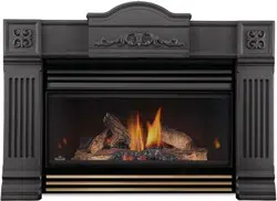
It’s important to periodically perform a visual check of the pilot and
burner fl ames. Compare them to the illustrations provided. If any fl ame
appears abnormal call a service person.
3/8” - 1/2”
(9.5mm - 12.7mm)
6.3 FLAME CHARACTERISTICS
6.4 BLOWER REPLACEMENT
This appliance comes standard with a blower, a heat sensor, variable on/off speed control and a power cord.
Because the blower is thermally activated, when turned on, it will automatically start approximately 15 minutes
after lighting the appliance and will run for approximately 30 minutes after the appliance has been turned off.
Use of the fan increases the output of heat. Air, drawn in through the lower louvre access door, is driven up the
back of the fi rebox, and exhausted as hot air between the upper louvres.
!
WARNING
RISK OF FIRE AND ELECTRICAL SHOCK.
TURN OFF THE GAS AND ELECTRICAL POWER BEFORE SERVICING THIS APPLIANCE.
USE ONLY WOLF STEEL APPROVED OPTIONAL ACCESSORIES AND REPLACEMENT PARTS WITH
THIS APPLIANCE. USING NON-LISTED ACCESSORIES (BLOWERS, DOORS, LOUVRES, TRIMS, GAS
COMPONENTS, VENTING COMPONENTS, ETC.) COULD RESULT IN A SAFETY HAZARD AND WILL
VOID THE WARRANTY AND CERTIFICATION.
ENSURE THAT THE FAN’S POWER CORD IS NOT IN CONTACT WITH ANY SURFACE OF THE
APPLIANCE TO PREVENT ELECTRICAL SHOCK OR FIRE DAMAGE. DO NOT RUN THE POWER
CORD BENEATH THE APPLIANCE.
THE WIRE HARNESS PROVIDED IN THE BLOWER KIT IS A UNIVERSAL HARNESS. WHEN
INSTALLED, ENSURE THAT ANY EXCESS WIRE IS CONTAINED, PREVENTING IT FROM MAKING
CONTACT WITH MOVING OR HOT OBJECTS.
51.5
G
V
B
HEAT
VARIABLE SPEED SWITCH
FAN
SENSOR
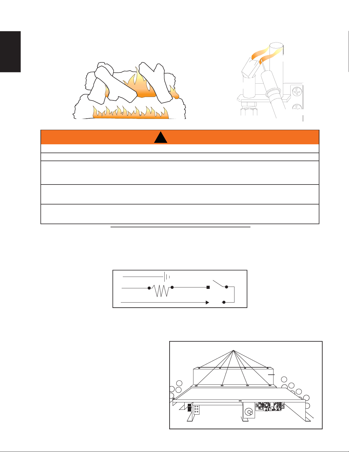
1. Turn off the gas and electric power to the appliance.
2. Remove the safety screen and upper glass bracket. Loosen the lower glass bracket and remove the glass.
3. Remove the logs, refer to " LOG PLACEMENT" section for detailed instructions.
8 SCREWS
ACCESS DOOR
BLOWER
DUCT
4. Remove the burner assembly.
5. Remove the eight screws holding the access
door in place on the control assembly (located
at the back of the burner support).
6. Remove the four screws holding the blower
duct and slide it forward from beneath the
burner support.
7. Disconnect the electrical connectors at the
blower.
8. Remove the blower.
9. To reinstall the blower reverse these steps.
PILOT BURNER
THERMOPILE
ELECTRODE
Loading ...
Loading ...
Loading ...