
Loading ...
Loading ...
Loading ...
Installation Instructions
DIRECT CONNECT APPLICATIONS
[] MAKE WIRE LEAD CONNECTIONS INSIDE THE JUNCTION BOX
1. Make all wirt <onnecfions I)7,"using appropriate L IAisted electrical connectol-s and technklues.
2, Sele(t the applicable wiring situation and follow tile instructions a(cordingf):
1-Phase 220-240 VAC
II 7a-'t*c0mza/h_ lh_Zo_wtineto a si_l_dej_hasech_:uitp.
230V ap/dicalzo_ls:
Connect tile whim and black leads ot the Zoneline
power supply kit to tim bcanch circuit LI and L2
leads. (The white lead ot th{ power _uppl} kit should
be klentified b) tbe installer using elecu-ical tape with
some color other than green or white.) Connect the
g_*en kad of the power supply kit to the power
suppl 3 and branch circuit ground.
3-Phase 208 VAC
l_7*enioHm_di,g the Zom'lhle to a tk_Pphase ch_uit fin
207;I"app/icati0ns:
Connect the white and black leads of the Zoneline
power supply kit 1o the branch circuit LI and L2
leads. (The white lead of' 1he power _upply kit shouM
be identified by tile installer using electrical rope with
some color otber than green or white.) Connect the
green lead of tile power supply kit to the pow(r
supply an(I 1)l_u_chcircuit gromM.
3-Phase 208 VAC with "Crazy Leg"
ll Tlen co_z_zellh_g the Zo_ldhu, to a lk_laff_haae ih_ u# with
"(hrlq_ l<<" ior 208V app/icalio_s:
Connect tile white and black \ads ot the Zoneline
power supply kit to tim bmn(h cir_ uit N(umd and L1
leads. (The white lead of the power suppl) kit shouM
be connected to netm-dl.) Com_ect tim green lead ot
the power suppl) kit to the power supply mM bramh
circuit ground.
3-Phase 253-277 VAC
II 7n'n c0_zna/b_g the Zmwlhze to a lk_l'@ha*e ih_ ui/ fi,
265V applicatio_ls:
Conne(l tim whim mM bla_k leads of the Zon(line
po_ er supply kit 1o the bran< h drcuit Neutral mM El
leads. (The white l(ad ot ll_e power supply kil shouM
be connect(d to neut_wl.) Connect the green lead ol
the power supply kit to tim power supply and branch
circuit ground.
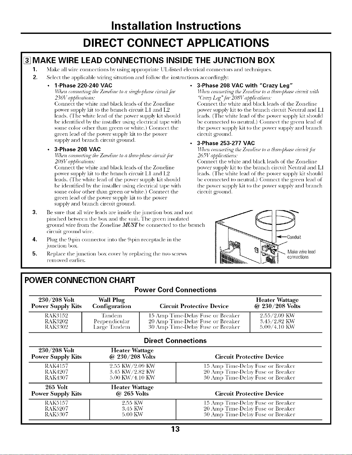
3, Be sme flint all wire leads are inside tim junction box and not
pindmd bel_een the box and the unit. The green insulated
ground wire from th( Zoneline MUST be conneck d 1o the bl-dnch
cir(uit ground wire.
4, Plug the 9-pin COllllector into tile 9-pin rec( ptacle in the
junction box.
5, Replace th( junction box cov(r by replacing the lwo screw_
removed (arliel;
Makewirelead
connections
POWER CONNECTION CHART
Power Cord Connections
230/208 Volt Wall Plug
Power Supply Kits Configuration
KkK3152
1_\K3202
RkK3302
"Ihndem
Perix ndicular
Large "Ihndeln
Heater Wattage
Circuit Protective Device @ 230/208 Volts
15 Amp Time4)_ lay Fuse o1 Br(aker
20 Amp Time4)elay Fuse or Br(ak(r
30 Amp Tinae-D_ lay Fuse or Br(aker
2.55/2.09 K_V
3.45/2.82 t'_VvT
5.00/4.10 KW
Direct Connections
230/208 Volt
Power Supply Kits
1_\K4157
KkK4207
1_\K4307
265 Volt
Power Supply Kits
KkKSI57
KKK5207
K\K5307
Heater _rattage
@ 230/208 Volts Circuit Protective Device
2.55 KVvTi2.09 K1_V 15 Amp "['im_-Dela} Fuse or Breaker
3.45 KVvTi2.82 K\V 20 Amp Time-Dela} Fuse or Breaker
5.00 KW!4.10 KW 30 Amp Time-Dela} Fuse or Breaker
Heater Wattage
@ 265 Volts Circuit Protective Device
2.55 KW 15 Amp "['ime-Del_l} Fus_ or l',l-e;ikt'l-
3.45 KW 20 Amp Time-Dela} Fuse or Breaker
5.00 KD,7 31)Amp Time-Dela} Fus_ or Break(r
13
Loading ...
Loading ...
Loading ...