ge.com
o_
Safety Instructions ........... 2
Operating It_truc¢ions
Controls--Dip Swit( hes ...... 3-5
Comrols--T_ rminaI
Comle( tions .............. 6, 7
On/Off Swit( h ............... 8
\\ milation Control ........... 8
Care and Cleaning
Air Fihers ................... 9
Base Pan ................... 9
Exhaust Coils ................ 9
Installation Instructions
Ele(trk al Supply ......... 11-13
Installing the Zoneline .... |4-91
Preparation ................ 10
Servicing .................. 22
Troubleshooting _l_ps ....... 93
Normal ()p_ rating Sounds .... 24
Consumer Support
Consum(r Support . . .Back Cover
Product R(gistration ...... 25, 26
Wa rra_l _v .................. 27
Heal/Cool and
Heal Pum/_ Models
7500 Series
Write the model and serial
numbers here:
Model #
Serial #
Find these numbers on a label
on the flont case pmlel.
TINSEA469JBRZ 49-7561 10-06JR

IMPORTANTSAFETYINFORMATION.
READALLINSTRUCTIONSBEFOREUSING.
WARNING!
Foryour safe_ the information in this manual must be followed to minimize the risk of fire, electric
shock, or to prevent property damage, personal injury, or loss of life.
_l I S
..,.__ SAFETYPRECAUTIONS
_,/_ • This Zoneline m s be prop _ ?
installed in a<<ordan(e with the
Installation [nsUuctions betbt-_ it is
used. See the Installation Instructions
in the back of this manual.
R_ place imm(diat(ly all (lectric service
cords thal have becom( IF,fled or
odmrwise damag< d. A damag(d pow(r
supply (ord must be replaced with a
new pow<r supply coi*t obtained from
the manuf_ictm'er and not repaired.
Do no{ use a cord dmt shows ctvlcks or
abrasion damage along its length or at
(ith( r _1_ plug or col'me(tot (rid.
• Unplug or discmme(t tile Zoneline at
the fi_se box or circuit break( r betore
making any repairs.
NOTE: W_ strongly recommend dmt any
s<rvi_ ing be p_ rfbrm_ d l>y a qualified
individual.
• All air conditioners contain refl'igerants,
which trader fi_,deral law must be
removed prior to product disposal. If
you are ge{ting rid of an old produ({
with refi-igerants, che(k with the
company handling disposal about what
to do.
_Qf'_'.; READANDFOLLOWTHISSAFETYINFORMATIONCAREFULLY.
I _U'\_ SAVETHESEINSTRUCTIONS
2
Controls-dipswitches. o.oom
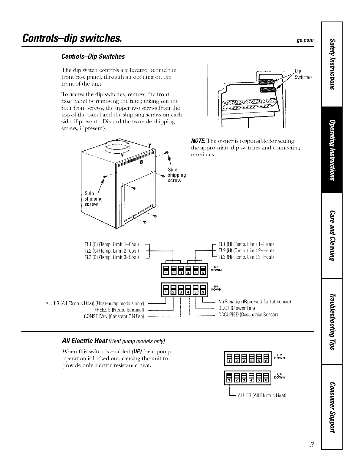
Controls-DipSwitches
Tim di 1)_wixch cc,nlrols are localed l:,ehind th_
fronl case panel, through an opening on lh(
front of the trait.
"1\__mcess tile dip switch(s, rcmovc tile fl-ont
case panel by r_ moving tile fihe_; raking out tile
tk_ur h-ont screws the upper two screws from the
top ot th( panel und the shipping screws on euda
side, il present. (Disc_wd the two sid( shipping
screws, if present).
NOT£"The owzler is responsil)le f_)l-settin
the appropriate dip switches and connecxing
terminals.
Side
shipping
screw
TL1(C)(Temp.Limit1-Cool)
TL2(C)(Temp.Limit2-Cool)
TL3(C)(Temp.Limit3-Cool)
ALLFR(All ElectricHeat)(Heat_pumpmodelsonly) --
FREEZS(FreezeSentinel)
CONSTFAN(ConstantONFan)
F TL1(H)(Temp.Limit1-Heat)
TL2(H)(Temp.Limit2-Heat)
TL3(H)(TempLimit3-Heat)
_1 ,--L-_ ,-.b. _- •
I I I I I I
$$$$$$ 0.
DOWN
All Electric Heat (Heatpumpmodelsonl V)
Wh(n this switch is (nabl(d (UP), h(at pump
op(ration is lo(k(d out, (ausing the unit 1o
proxid( only ekctri( resismn(( h(at.
BSma$$ °°
DOWN
LBBBBB
ALL12R(All ElectricHeat)
3
Controls-dipswitches.
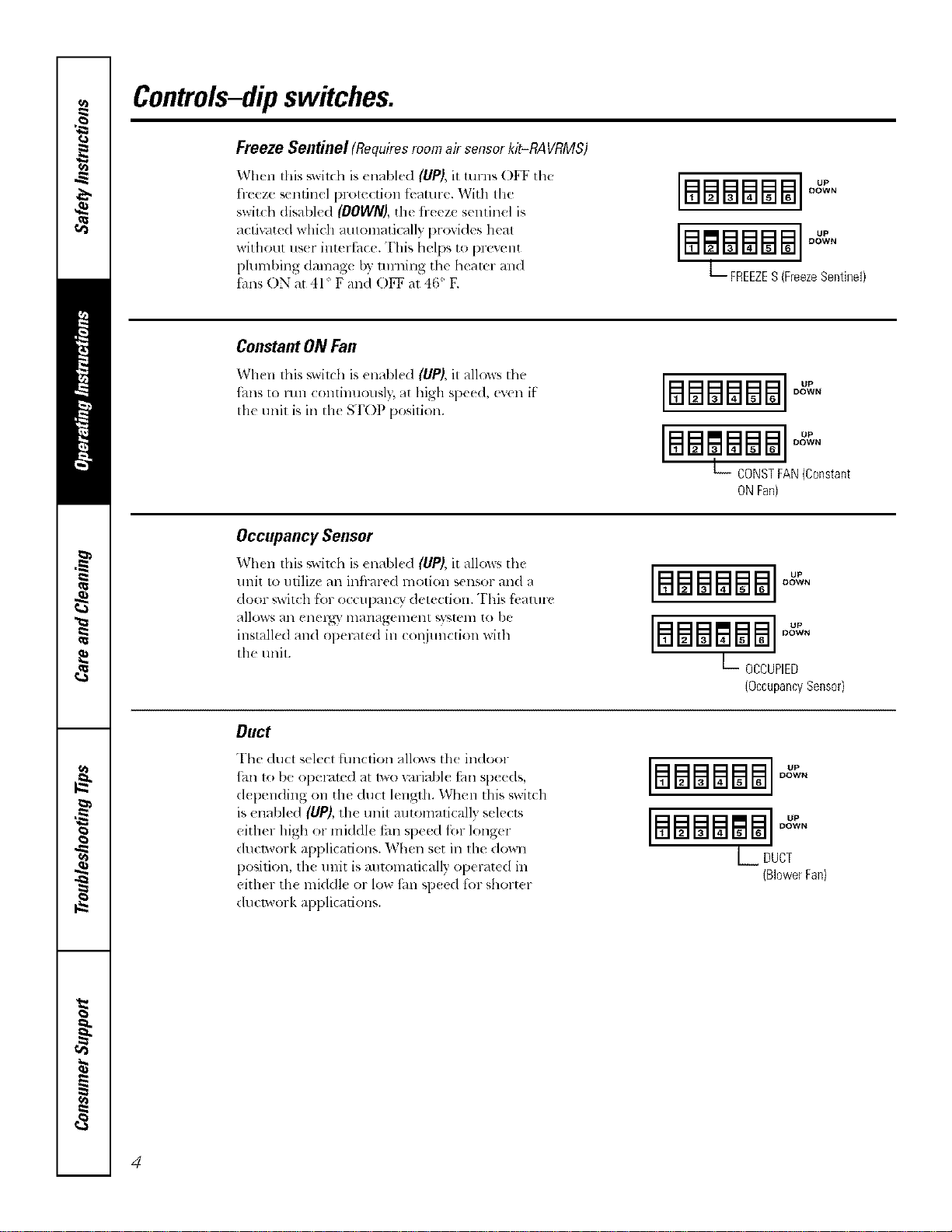
Freeze Sentinel (Requiresroomair sensorkit-RAVRMS)
When this _wilda is enabled (UP), it ulrns OFF the
fl-eeze sentinel protection tbature. With the
switch disabled (DOWN), the fl-eeze sentinel is
actiu/ted which automatically provides heat
without us(r intertbce. This helps to [)revent
pluml)ing damag_ by turning the hearer and
thns ON at 41 ° F and O1_ at 46' E
IBEaBBBBI
DOWN
[#lmBm8l ]°"
DOWN
L FREEZES(FreezeSentinel)
ConstantONFan
When this switd_ is un_d_h'd (UP), it a]low_ tll_'
_hns to lun continuously, at high speed, even if
tile unit is ill tile STOP position.
[mmmmm °"
DOWN
BSglSB8
DOWN
L_ CONSTFAN(Constant
ONFan}
Occupancy Sensor
When this _witdl is enabled (liP), it allo_s the
unit to utilize an infl-ared motion sensor and a
door ,;witch fbr o( cupanQ" detection. This fi,aturc
allows an enel_" management _,yamm to be
installed and operated in COiljunction with
the trait.
[B88#188]OXeN
B88glS8
DOWN
L OCCUPIED
(OccupancySensor}
Duct
The <luct select fimction allows th< indoor
_hn to be operamd at lWOv_lriabl_ tm speeds,
d{ pending on the ducl length. When this switch
is enabled (UP), the unit mltomalically selects
either high or middle tm speed fi_r longer
ducp, vork applications. When set ill llle down
position, th_ u nit is mltomatically operated in
either th_ mkldle or low tim sp_ed lot short_ r
dtlclwork applications.
DOWN
BBBBBB °"
DOWN
L DUCT
(BlowerFan)
4
ge.com
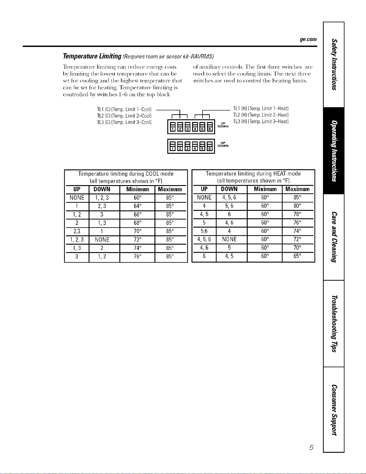
TemperatureLimitiug(Requiresroom airsensor kit-RAVRMS)
"12,mperamre limiting can reduc((nerg) costs
by limiting tile lowest temperature that can be
set for cooling and the highest mml)eramre that
call b( set for heating. "Ik'mperamre limiting is
controlled bv v_vitches 1-6 on the top block
of auxilialw contr,,4s. The fit-,tthre( switches are
use(1 to sol(c1 tilt (ooling lilnits. Th( n(xt tln-ee
sx_itches are used to (ontrol the heating limits.
TL1(C)(Temp.Limit1-0oo0
TL2(C)(Temp.Limit2-Cool) |
TL3(C,(Temp.Limit3-Coo0 [[_]_] u.
DOWN
[BSBSBS]°°
DO_v'VN
TL1(H}(Temp.Limit 1-Heat)
TL2(H)(Temp.Limit2-Heat)
TL3(H)(Temp.Limit3-Heat)
I
UP
NONE
1
1,2
2
2,3
1.2,3
1,3
3
Temperature limiting during COOLmode
(all temperatures shown in °F)
DOWN
1,2,3
2,3
3
1,3
1
NONE
2
1,2
I
Minimum Maximum
60° 85°
64° 85°
66° 85°
68° 85°
70° 85°
72° 85°
74° 85°
76° 85°
Temperature limiting during HEATmode
(all temperatures shown in °F)
UP
NONE
4
4,5
5
5.6
4.5.6
4,6
6
DOWN
4,5.6
5.6
6
4,6
4
NONE
5
4.5
Minimmn
60°
60°
60°
60°
60°
60°
60°
60°
Maximum
85°
80°
78°
76°
74°
72°
70°
65°
5
Controls--terminal connections.
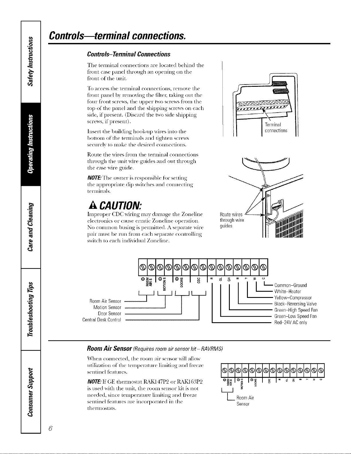
Controls-Terminal Connections
The terminal conn,(lions ar( locate<l behind lh{
t"1-O111 (2_tS{_ }}{/ll_._l [hl'oll_h _111 op( llillg (Ill 111(
front of the unit.
"I() access lhe tel lnillal COlllleCtiOllS, l-ellvY, e tlle
hont panel by removing tile tiltm; taking out tile
t()lll" tl'llll[ screws, tile tipper two screws t}-oln tile
top of the panel and tile shipping scrcw_ on each
side, if present. (Discard th{ lwo side shipping
screws, if present).
Insert the building he,ok-up wilxs inlo the
I)ollo111 o[ tile 1_rnlinals and tighl_ n s_ rews
sectll-t Iv 1o lnake lhe desired COllllecti(_llS.
l_.Ol/le the wil-es tFOlll lll(f tel'lnille.l ( Olllle(liOllS
Ihrough d_e unit Mre guides and out through
Ill{ case wire guide.
NOTE:The owner is r{ Sl)Onsibl( fbr s{ uing
the appropriat( dip swit(hes and coral{ cting
t{ rlninals.
A CAUTION:
Improper CDC wit ing may damage the Zonelin{ Route wires
electronics or (aus{ {rl-4ti( Zoneline op{ l-ntion, through wire
No common busing is pem_itt{ (1.A separ4te wire guides
pair must be mn ti-_an each separate controlling
switch to each individual Zoneline.
I I
== g g
Motion Sensor
DoorSensor
CentralDeskControl
g
I t L Common-Ground
-- White-Heater
Yellow-Compressor
Black-ReversingValve
Green-High Speed Fan
Green-LowSpeedFae
Red-24VAC0nly
Room Air Sensor (Requiresroom airsensorkit - RAVRMS)
When corn1{ ct_d, th{ room air s{ nsor will allow
utilization ot the t{ml){ laturt limiting aim lr_eze
s{ntin{l t( all II(:s.
NOTE:If GE thermostat 14\K147t)2 or lgkK163P2
is used with the unit, the room sensor kit is not
needed, since tempel-4tm-e limiting and ti-e{ z{
sentinel tbatures are in(olpol-4ted in the
therlllOStats.
OOOOOOOOOOOOOOO
L RoomAir
Seesor
6
ge.com
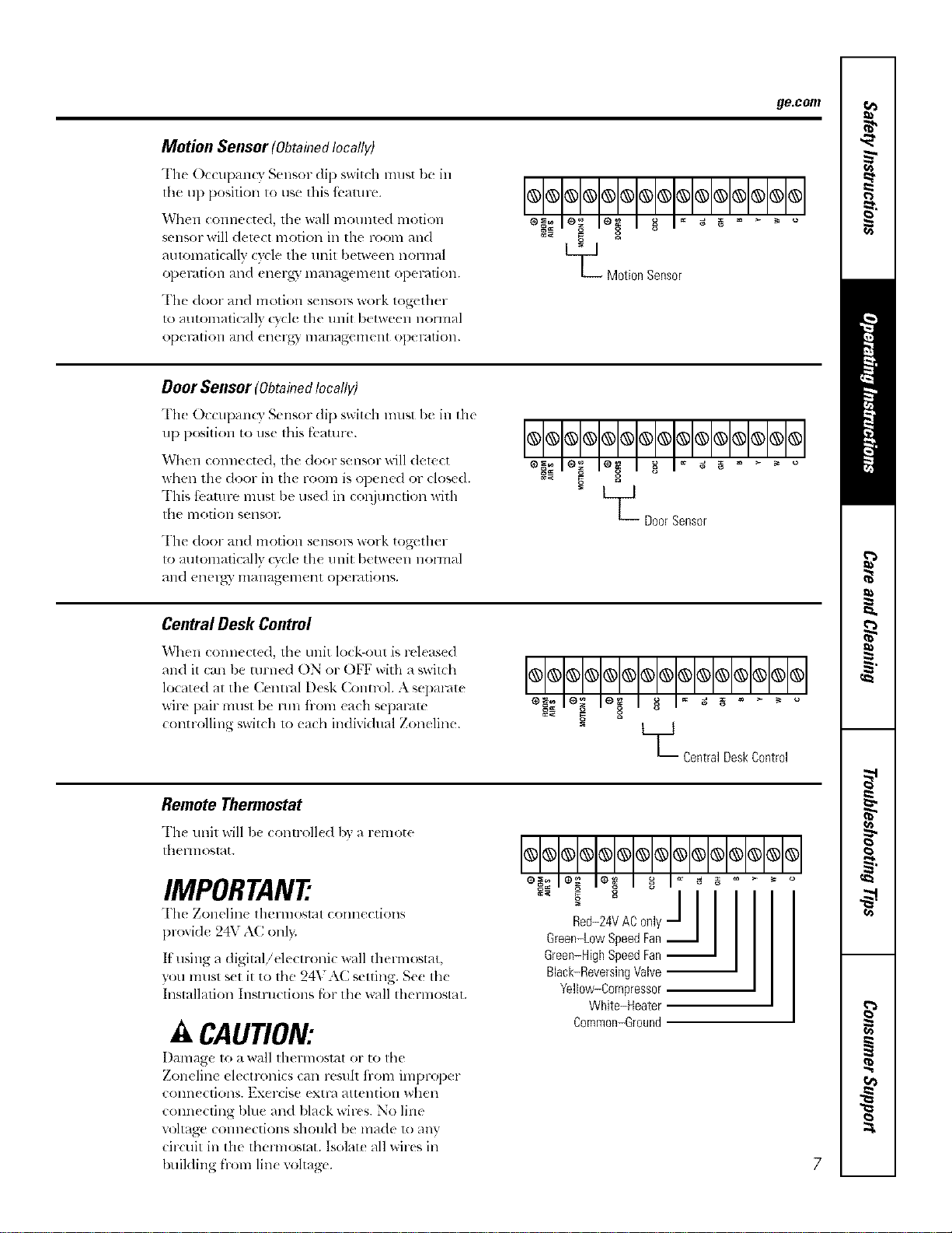
Motion Sensor(ObtahTedlocally)
The Occupan( 3 Sensor di1) switch must be in
lhe up position to use this fi..amre.
When connected, tile wall mounted motion
sensor will detect motion in lhe room and
aulomaticallv cycle th( unil I)etween noHnal
ol)el_dtiOll alld ell( 1-_,3' lllall_t_t_ell]( 111 Ol)eF_?tiOll,
The door and motion sensols work together
u) automatically c}cle the unit b(tween normal
ol)el_/tiOll alld (llerg) lllallag(,lllellt ol)el'dtiOll.
L_ Motion Sensor
Door Sensor (ObtahTedlocally)
Th_ OccupanQ" Sensor (lip switch must be in tile
up position to use this fbaulre.
When connected, the door sensor will delect
when th( door in tile room is opened or closed.
This tbamre lnusl be use(1 ill col_junetion witll
tile 11]o1]Oll SellSOE
The door and motion sensolY, work together
to automatically cycle the unit between nolmal
_tll(l ellel_)" ill_lllagel_lellt ol)el-_ltiOllS.
OO@OO®OOOOOOO@O
- L__ DoorSensor
Central Desk Control
When connected, the unit lock-out is released
and il can be turned ON or OFF with a swilch
locat(d at the Cenn-al Desk Colm-ol. A separate
wire pair mtlst be mn iiom each sepalam
controlling switch 1o each individual Zoneline.
_Central DeskControl
Remote Thermostat
The unit will be (ontr_lled by _lremote
theHnosl_t.
IMPORTANT
The Zonelin( thermostat connections
provide 24V A(onl).
It tlSillg a digitalielectroni( wall thel-lllostat,
you must s(t it to the 24VAC setting. Se( the
Installation Instructions l;ar th( _ll thermostat.
A CAUTION:
Damage to a wall lhermostal or to tile
Zoneline electronics can resuh ii-om improper
COlllleCliOllS. Exercise extl-a attention whell
connecting bhle and black wir(s. No line
u)ltage connections should be made u_ any
circuit in the thermostat. Isolate all wires ill
building from line voltage'.
@@@@@@@@@@@@@@@
Black-ReversingVNve
Yellow-Compressor
White-Heater
Common-Ground
7
OtherfeaturesofyourZoneline.
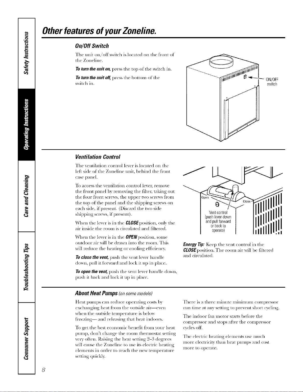
On/Off Switch
Thc unit on/'otf_,wil(h is located on Ill(' front ot
tile Zon( line.
Toturntheuniton,pre_sthe top ot the swit(h in.
ToturntheunitoK l)r(ss the bottom ot the
switchin.
ON/OFF
switch
Ventilation Control
The retaliation conuol lever is localed on the
l(fl sid( of tile Zoneline unit, behind the front
case panel.
To access the ventilation control levm; remove
the front panel by removing the filtel; raking out
the four front screws, the upper two screws fl-om
the top of the panel and the shipl)ing screws on
each side, it present. (Discard the Iwo hide
shipping scl*:ws, it present).
When the lever is in the CLOSEposition, onh the
air inside the rooln is circulat_ d and filmred.
When the lever is in the OPENposition, some
outdoor air will lye drown into the room. This
will reduce the heating or cooling etficiem3:
Toclosethevent,[)ush tim vent lever handle
down, pull it t;nl_vard an(I lock it up ill place.
Toopen the vent, push the vent lever handle down,
push it/)ack and lock it u l) ill place.
Ventcontrol
(push[everdown
andpullforward
orbackto
operatel
Energy Tip: K_e l) the vent COlltr()l ill the
CLOSEl)osition. The room air will be filt_ rtd
and circulated.
II
=i
About Heat Pumps (onsomemodels)
Ileal pumps can reduce opel-,iting costs by
exchanging heat from tile oulside ail_-even
when tile outside temperature is/)elow
h>ezing-- and r(leasing that heat indoors.
"Ik)get the best economic 1)enetit fi-om your heat
Dt]ml), (lon't change the room thelmoslat setting
vcWoften. R_dsing lhe heat selling 2-3 degrees
will cruise tile Zoneline 1o use its electric h(ating
elements in ord(r to reach tile new tempemtmx
s(tting (luickl):
Ther( is a tlm'e minum milfinmln coml)r(ssor
run time at any setting to pr(v(nt short cycling.
The indoor t;m motor slarts belknx, th(
coml)res*or and slops atier tile compressor
cvcl(s eli.
The (lecuic heating elemenls use much
molv electricity than heat l)UmpS and cost
lnoru to oper4te.
8
Careandcleaning, gecom
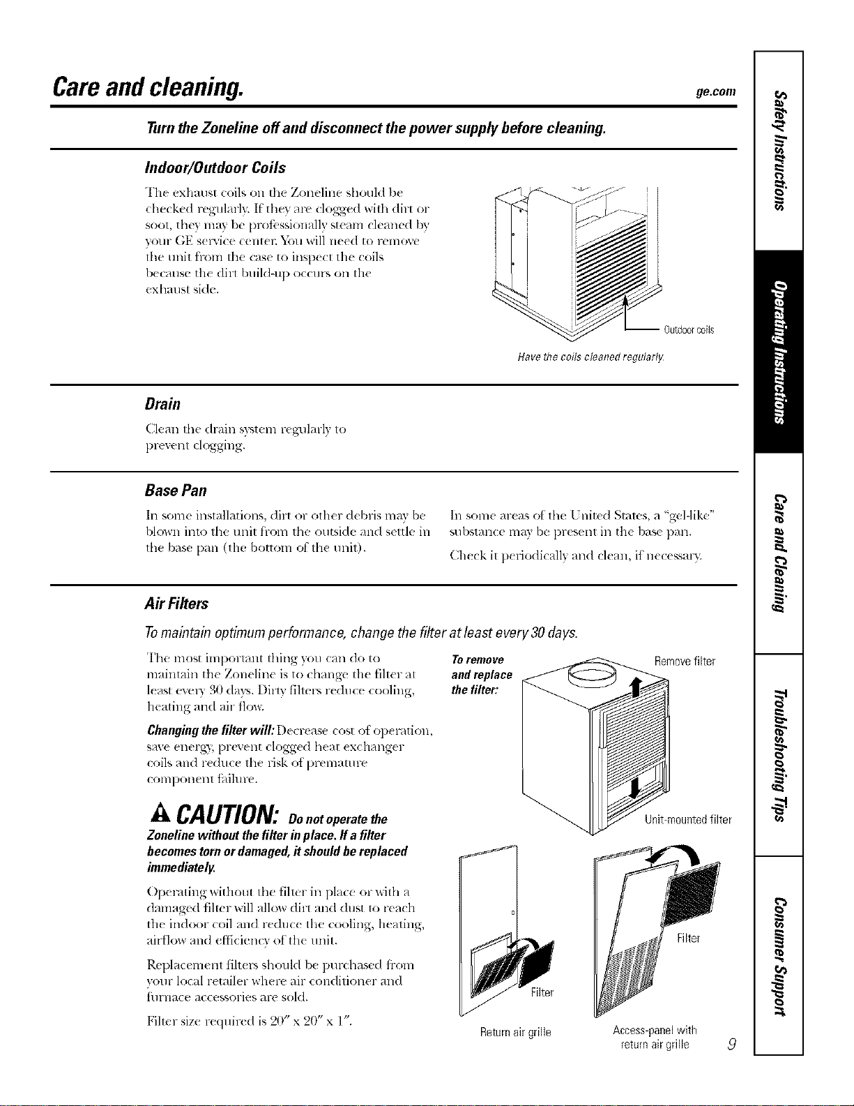
Turn the Zoneliue off and disconnect the power supply before cleaning.
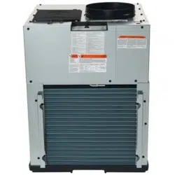
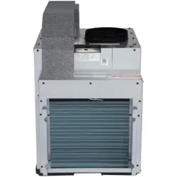
Indoor/Outdoor Coils
The exhaust (:oilson the Zoneline should be
checked regularly. If'they are clogged will_dirl or
soot, they may l)e prot;._ssionall} steam cleaned by
your GE s( iMce (:ent_ l:D)u will need to remoxe
lhe unit h-ore the case to inspecl the coils
because the dirl buildqlp occurs on the
exhaust side.
-- Outdoorcoils
Have the coils cleaned regularlg
Drain
Clt'ma fl_edrain w_tem re_ulm-ly to
prexent clogging.
Base Pan
In some installations, dirt or olher debris may be
blown into the unit from the outside and settle in
fl_e base l)an 0he bottom of the unit).
In some areas of ll_e 17hired Stares, a "gel-like"
substance may be l)resent in the base pan.
Check it periodically and clean, if"necessal);
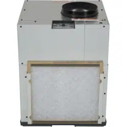
AirFilters
Tomaintain optimum performance, change the filter at least every 30days.
The most important thing you can do to Toremove
maintain the Zoneline is to changt, the filter at and replace
least ev(qy 30 days. Dim fihers reduce cooling, the filter:
heating and air flo_;
Changing the filter will: [)(crease cost el el:){ ration,
save energy, prevent clogged heat ex( hanger
coils and reduce the risk ot l)rematu re
coral)orient tbihlre.
A CAUTION:Oo.o,operatethe
Zonelinewithoutthefilterinplace,ffa filter
becomestornordamaged,itshouldbereplaced
immediately.
Operating without the filmr in place or with a
damagv(I filmr will allow dirt an(I dust to reach
the indoor coil an(I re(hlc( the cooling, heating,
airflow and efticien O of the unit.
Rel)lacemenl tilt(rs should b( l)urchased fi-om
vour local retailer where air conditioner and
filrnace accessories are sold.
Fihcr size required is 20" x 20" x l".
Filter
Returnair grille
Removefilter
Unit-mountedfilter
Filter
Access-panelwith
returnair grille
9
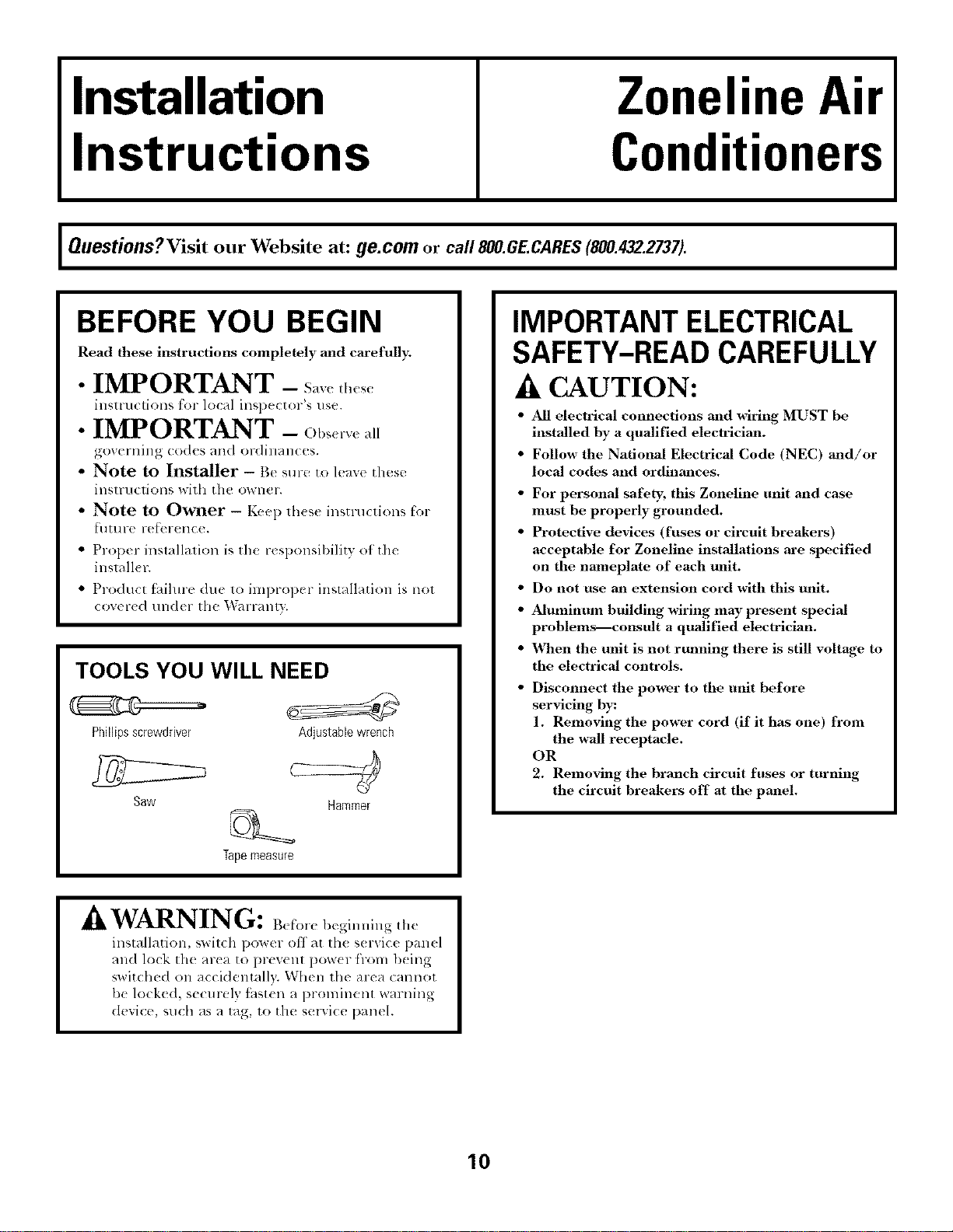
Installation
Instructions
Zoneline Air
Conditioners
Questions?Visit our Website at: ge.com or call 800.GE.CARES(800.432.2737).
BEFORE YOU BEGIN
Read these instructions completely and carefully;
• IMPORTANT - S_ve_l,,,_,,
inslru< lions for local insl)ector's use.
• IMPORTANT - Ob_,rv<a,
,_()V(_l'l]illg (od(s alld or(lill_)l]( (s.
• Note to Installer - Be sure to leave these
illSIrllCliOllS D,:ilh [hc O_*IlCl ",
• Note to Owner - Keep lhese insuuctions for
t?[] [!1 r( , ix,l?el-(llC().
• Prop< r installalion is the r_ sponsibility of the
inslall¢ r.
• Product t_dlme due 1o iml)ropcr installation is nol
COY( r(d t/ll<h r th( l_garranty.
TOOLS YOU WILL NEED
Phillipsscrewdriver
Saw
Adjustablewrench
Hammer
Tapemeasure
IMPORTANT ELECTRICAL
SAFETY-READ CAREFULLY
A CAUTION:
• All electrical connections and wiring MUST be
installed by a qualified electrician.
• Follow the National Electrical Code (NEC) and/or
local codes and ordinances.
• For personal safety, this Zoneline unit and case
must be properly grounded.
• Protective devices (fuses or circuit breakers)
acceptable for Zoneline installations are specified
on the nameplate of each unit.
• Do not use an extension cord with this unit.
• Aluminum building wiring may present special
problemsIconsult a qualified electrician.
• X_,_en the unit is not rulming there is still voltage to
the electrical controls.
Disconnect the power to |he unit before
servicing by:
1. Removing the power cord (if it has one) from
the wall receptacle.
OR
2. Removing the branch circuit fuses or turning
the circuit breakers off at the panel.
A IATA DgTT'_T_
_Jk VVZ']UL_NJIL±_IU: B_l_'or_ bcginuing the
installation, switch power off at Ill( s( r_ice panel
and lock the area to prevent pow{r from being
switched on accidentally. When the area cannot
be locked, secmely thst_ n a prominent warning
dexice, such as a tag, to the smwice panel.
10
Installation Instructions
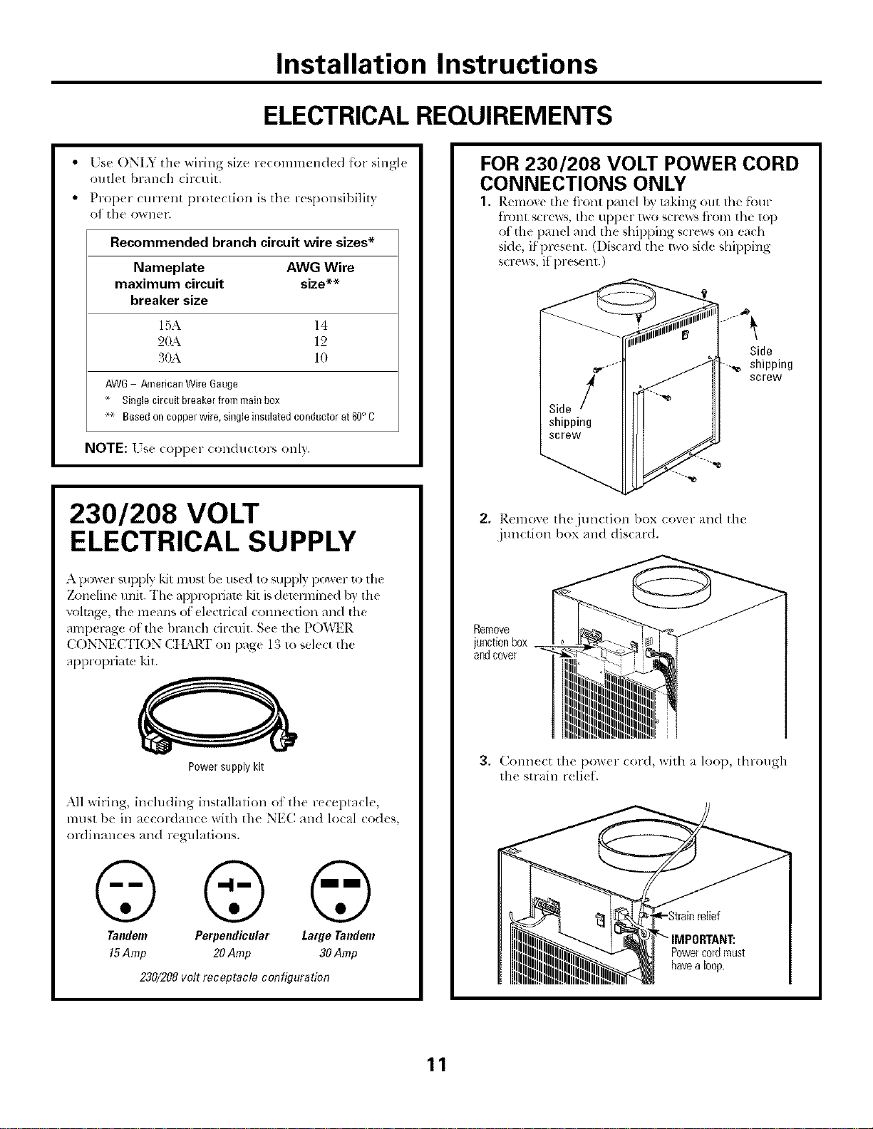
ELECTRICAL REQUIREMENTS
Lse ONLY the _siring size recolnlnend_ d for single
outlet branch (ir(uit.
Prop(r (urrent [}lOt{(tion is tilt r{sF, onsil)ility
of" th00_VllPI'.
Recommended branch circuit wire sizes*
Nameplate AWG Wire
maximum circuit size**
breaker size
15,\ 14
2(b\ 12
30A 10
AW6 /_nericanWireGauge
Singlecircuitbreakerfrommainbox
_ Basedoncopperwire,singleinsulatedconductorat60oC
NOTE: [ s( t opp(r conductors onl}.
230/208 VOLT
ELECTRICAL SUPPLY
A power _,upply kit lnllst be used to supply power to the
7_)neline refit. The apl)ropfiam "kit is demrmin(d b'¢ the
voltage, the means ot el_ ctlJcal connection and the
amperage of the bl-dnch circuit. S¢e the PO'i,\_R
( ONNECTION CtL",RT Oll page 13 to sel_ ct the
appropriate kit.
Power supply kit
All wiring, including installalion ot the r(ceplacle,
ln[Isl be ill _/CCol-dallC(_ with the NE(I alld local codes,
ordilaan(:(s and regulations.
©©@
Tandem Perpendicular Large Tandem
15Amp 20Amp 30 Amp
230/208volt receptacle configuration
FOR 230/208 VOLT POWER CORD
CONNECTIONS ONLY
1. Rcmoxc th( i)-ont pmlcl b} taking out the fk_ul-
tront screws, the upper two scr('ws liom the top
of the panel and tile shippillg screws on each
side, if present. (I)iscard the two side shipping
screw_,, it present.)
Side
shipping
screw
2. ]_.elnox,'e Ih(jllll(Iiol] box (ovtr }/lid the
junction box and discard.
Remove
junctionbox __
andcover
3. (_onn((:t the pom,(!r (:or(l, with a loop, through
the strain reli( 1.
Powercordnrust
havealoop.
11
Installation Instructions
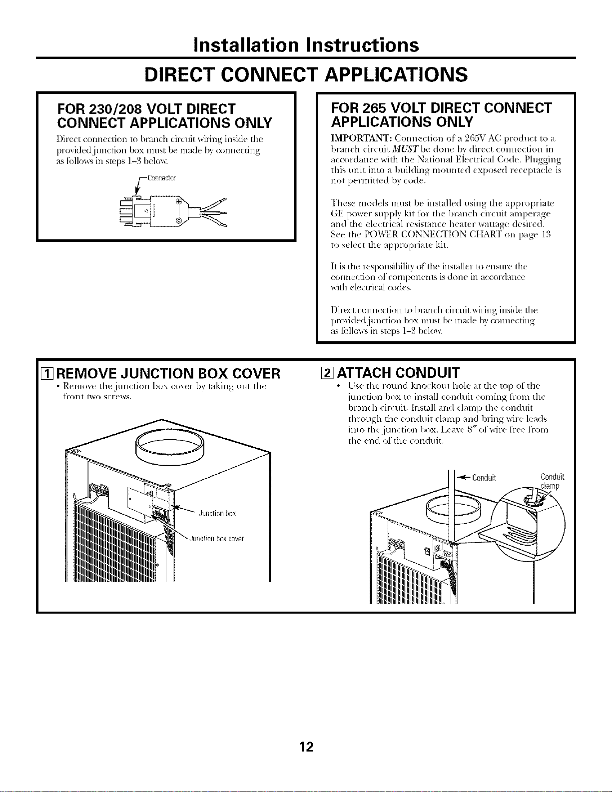
DIRECT CONNECT APPLICATIONS
FOR 230/208 VOLT DIRECT
CONNECT APPLICATIONS ONLY
Direct conn_ ction to branch circuil wiring inside th_
provided junction box must I)_made b? connecting
as follows in sI;(ps 1-3 belos_
_/-Connector
FOR 265 VOLT DIRECT CONNECT
APPLICATIONS ONLY
IMPORTANT: Commction of a 265V AC product to a
branch circuit MUST be done by direct connection in
accordance with the National Eiectrical (;ode. Plugging
this unit inlo a building mounted exposed r_ceptacl_ is
not pennitled by {:ode.
These models must be installed using th( applopriate
GE power supply kit ibr the blanch circuit amperage
and the (lectrical resistance h(ater wattag( desired.
See the POWER CONNECTION CtIART on page 13
to s_lect the applopriate kit.
It is the lesponsibility of the installer to <nsure th(
(Ollllec[iol] of (OlllpOll( Ills is (]Olle ill _l((ord_/llce
with el_ctrical codes.
I)irecl:connection 1o branch circuit _dring insid_ tim
plo'dded junction box must 1)<made by connecting
as follos_sill Slq)S 1--3below.
[] REMOVE JUNCTION BOX COVER
• Remov( th( jun(tion box (o_er by laking out th{
[?1"(111[ [_0 SCI'( _NS.
[] ATTACH CONDUIT
• [ sc the roun(1 kno(koul hole at the top ol the
junction box to install conduit coming hom tile
branch circuit. Install and clamp the conduit
through the conduit clam 1)and bring wire leads
inlo the junction box. Leave 8" of wire h-ee [l-Oln
the _nd of the conduit.
Conduit Conduit
12
Installation Instructions
DIRECT CONNECT APPLICATIONS
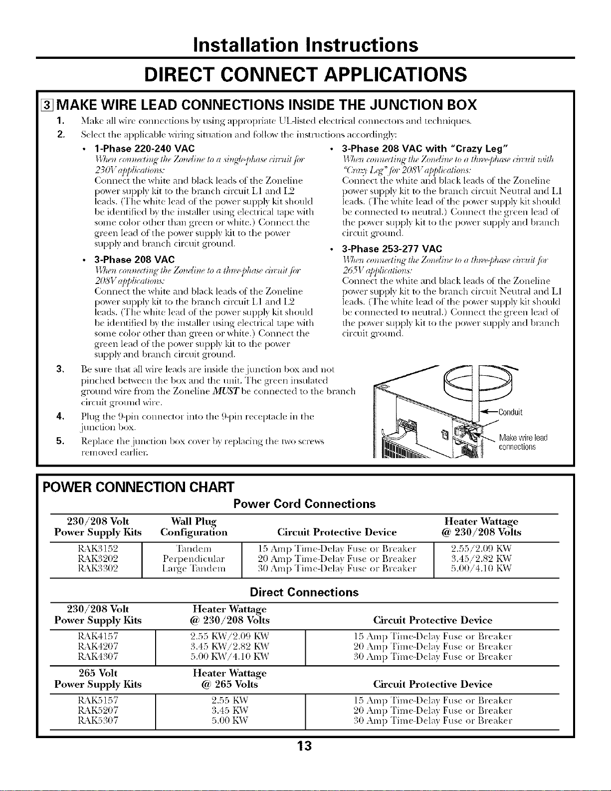
[] MAKE WIRE LEAD CONNECTIONS INSIDE THE JUNCTION BOX
1. Make all wirt <onnecfions I)7,"using appropriate L IAisted electrical connectol-s and technklues.
2, Sele(t the applicable wiring situation and follow tile instructions a(cordingf):
1-Phase 220-240 VAC
II 7a-'t*c0mza/h_ lh_Zo_wtineto a si_l_dej_hasech_:uitp.
230V ap/dicalzo_ls:
Connect tile whim and black leads ot the Zoneline
power supply kit to tim bcanch circuit LI and L2
leads. (The white lead ot th{ power _uppl} kit should
be klentified b) tbe installer using elecu-ical tape with
some color other than green or white.) Connect the
g_*en kad of the power supply kit to the power
suppl 3 and branch circuit ground.
3-Phase 208 VAC
l_7*enioHm_di,g the Zom'lhle to a tk_Pphase ch_uit fin
207;I"app/icati0ns:
Connect the white and black leads of the Zoneline
power supply kit 1o the branch circuit LI and L2
leads. (The white lead of' 1he power _upply kit shouM
be identified by tile installer using electrical rope with
some color otber than green or white.) Connect the
green lead of tile power supply kit to the pow(r
supply an(I 1)l_u_chcircuit gromM.
3-Phase 208 VAC with "Crazy Leg"
ll Tlen co_z_zellh_g the Zo_ldhu, to a lk_laff_haae ih_ u# with
"(hrlq_ l<<" ior 208V app/icalio_s:
Connect tile white and black \ads ot the Zoneline
power supply kit to tim bmn(h cir_ uit N(umd and L1
leads. (The white lead of the power suppl) kit shouM
be connected to netm-dl.) Com_ect tim green lead ot
the power suppl) kit to the power supply mM bramh
circuit ground.
3-Phase 253-277 VAC
II 7n'n c0_zna/b_g the Zmwlhze to a lk_l'@ha*e ih_ ui/ fi,
265V applicatio_ls:
Conne(l tim whim mM bla_k leads of the Zon(line
po_ er supply kit 1o the bran< h drcuit Neutral mM El
leads. (The white l(ad ot ll_e power supply kil shouM
be connect(d to neut_wl.) Connect the green lead ol
the power supply kit to tim power supply and branch
circuit ground.
3, Be sme flint all wire leads are inside tim junction box and not
pindmd bel_een the box and the unit. The green insulated
ground wire from th( Zoneline MUST be conneck d 1o the bl-dnch
cir(uit ground wire.
4, Plug the 9-pin COllllector into tile 9-pin rec( ptacle in the
junction box.
5, Replace th( junction box cov(r by replacing the lwo screw_
removed (arliel;
Makewirelead
connections
POWER CONNECTION CHART
Power Cord Connections
230/208 Volt Wall Plug
Power Supply Kits Configuration
KkK3152
1_\K3202
RkK3302
"Ihndem
Perix ndicular
Large "Ihndeln
Heater Wattage
Circuit Protective Device @ 230/208 Volts
15 Amp Time4)_ lay Fuse o1 Br(aker
20 Amp Time4)elay Fuse or Br(ak(r
30 Amp Tinae-D_ lay Fuse or Br(aker
2.55/2.09 K_V
3.45/2.82 t'_VvT
5.00/4.10 KW
Direct Connections
230/208 Volt
Power Supply Kits
1_\K4157
KkK4207
1_\K4307
265 Volt
Power Supply Kits
KkKSI57
KKK5207
K\K5307
Heater _rattage
@ 230/208 Volts Circuit Protective Device
2.55 KVvTi2.09 K1_V 15 Amp "['im_-Dela} Fuse or Breaker
3.45 KVvTi2.82 K\V 20 Amp Time-Dela} Fuse or Breaker
5.00 KW!4.10 KW 30 Amp Time-Dela} Fuse or Breaker
Heater Wattage
@ 265 Volts Circuit Protective Device
2.55 KW 15 Amp "['ime-Del_l} Fus_ or l',l-e;ikt'l-
3.45 KW 20 Amp Time-Dela} Fuse or Breaker
5.00 KD,7 31)Amp Time-Dela} Fus_ or Break(r
13
Installation Instructions
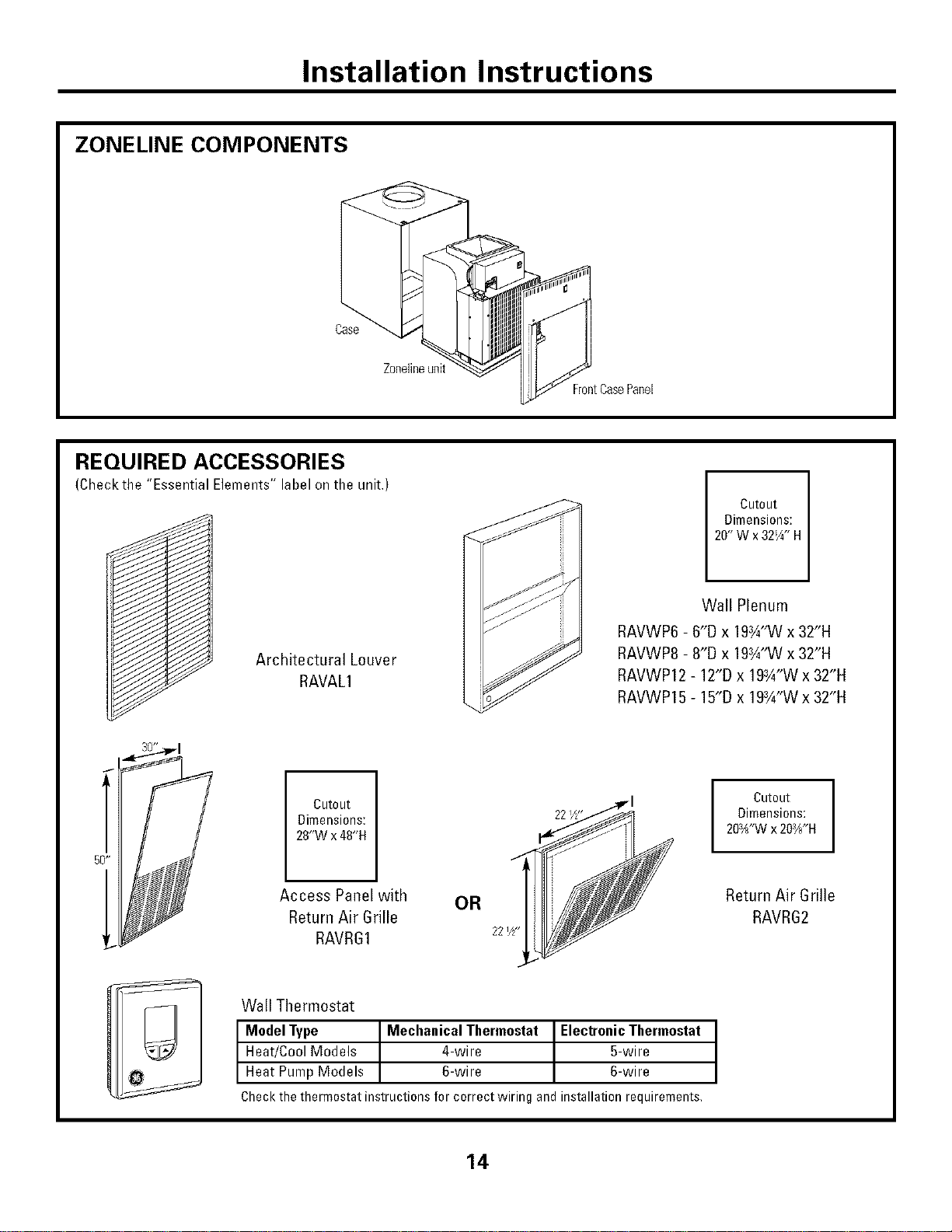
ZONELINE COMPONENTS
Case
Zonelineunit
FrontCasePanel
REQUIRED ACCESSORIES
(Checkthe "Essential Elements" label on the unit.)
/
Cutout
Dimensions:
20"Wx32W' H
Architectural Louver
RAVAL1
Wall Plenum
RAVWP6 - 6"D x 19¾"W x 32"H
RAVWP8 - 8"D x 19¾"W x 32"H
RAVWP12 - 12"D x 19¾"W x 32"H
RAVWP15 - 15"D x 19¾"W x 32"H
Cutout
Dimensions:
28"W x 48"H
I Cutout I
Dimensions:
203H'Wx 203//*H
Access Panel with OR
Return Air Grille
RAVRG1 221/2-
Return Air Grille
RAVRG2
Wall Thermostat
I ModelType MechanicalThermostat ElectronicThermostat
Heat/CoolModels 4-wire 5-wire
Heat PumpModels 6-wire 6-wire
Checkthethermostatinstructionsforcorrectwiringandinstallationrequirements,
14
Installation Instructions
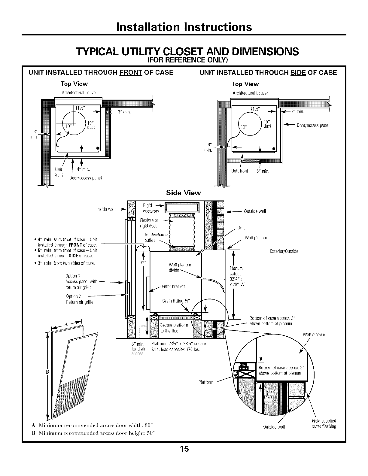
TYPICAL UTILITY CLOSET AND DIMENSIONS
(FOR REFERENCE ONLY)
UNIT INSTALLED THROUGH FRONT OF CASE
Top View
ArchitecturalLouver
UNIT INSTALLED THROUGH SIDE OF CASE
Top View
AmhitecturalLouver
4"ilgn.
Door/accesspanel
Side View
4 rain.fromfront of case Unit H
• , insidewall --_
H
installedthroughFRONTof case.
• 5" rain.fromfront of case Unit
installedthroughSIDEof case.
• 3" inill, fromtwo sides ofcase.
Option1
Accesspanelwith
returnairgrille
Option2
Returnairgrille
Rigid
ductwork-_fr _
Secureplatform
to the Roor
R" rain. Platform: 23¼" x 23¼" square
for drain Min. Dad capacity: 175 Ibs.
access
Plalform
Outsidewall
Unit
Wall plenum
t
Plenum
cutout
32¼" H
x 20" W
ql_ 3" rain. 7
Door/accesspanel
Exterior/Outside
Bottomof caseapprox 2"
abovebottom ofplenum
Wall plenum
8ottom ofcaseapprox.2"
abovebottomof plenum
_r
A Minimum recommended access door width: 30"
B Minimum re(ommerlded ac(ess door height: 50"
Outsidewall
Fieldsupplied
outer flashing
15
Installation Instructions
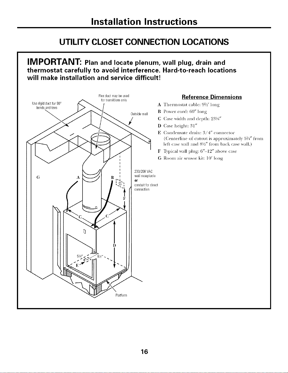
UTILITY CLOSET CONNECTION LOCATIONS
IMPORTANT: Plan and locate plenum, wall plug, drain and
thermostat carefully to avoid interference. Hard-to-reach locations
will make installation and service difficult!
Userigid ductfor 90°
bendsandtees
Flexductmay beused
for transitionsonly
Outsidewall
Reference Dimensions
A Thermostat cable: 9½' long
B Power _ord: 60" long
C Case width and d_pth: 23½"
D Case height: 31"
E Condensat_ drain: 3/4" conn_clor
(Centerline O[ cutout is approxinlately 51/4"from
left case wall and 8½" fi-om back cas< wall.)
F "Iypical wall plug: ('/'-12" abow: cas{
G Room air sensor kit: 10' long
230/208VAC
wall ieceptacle
or
conduitfor direct
connection
Platform
16
Installation Instructions
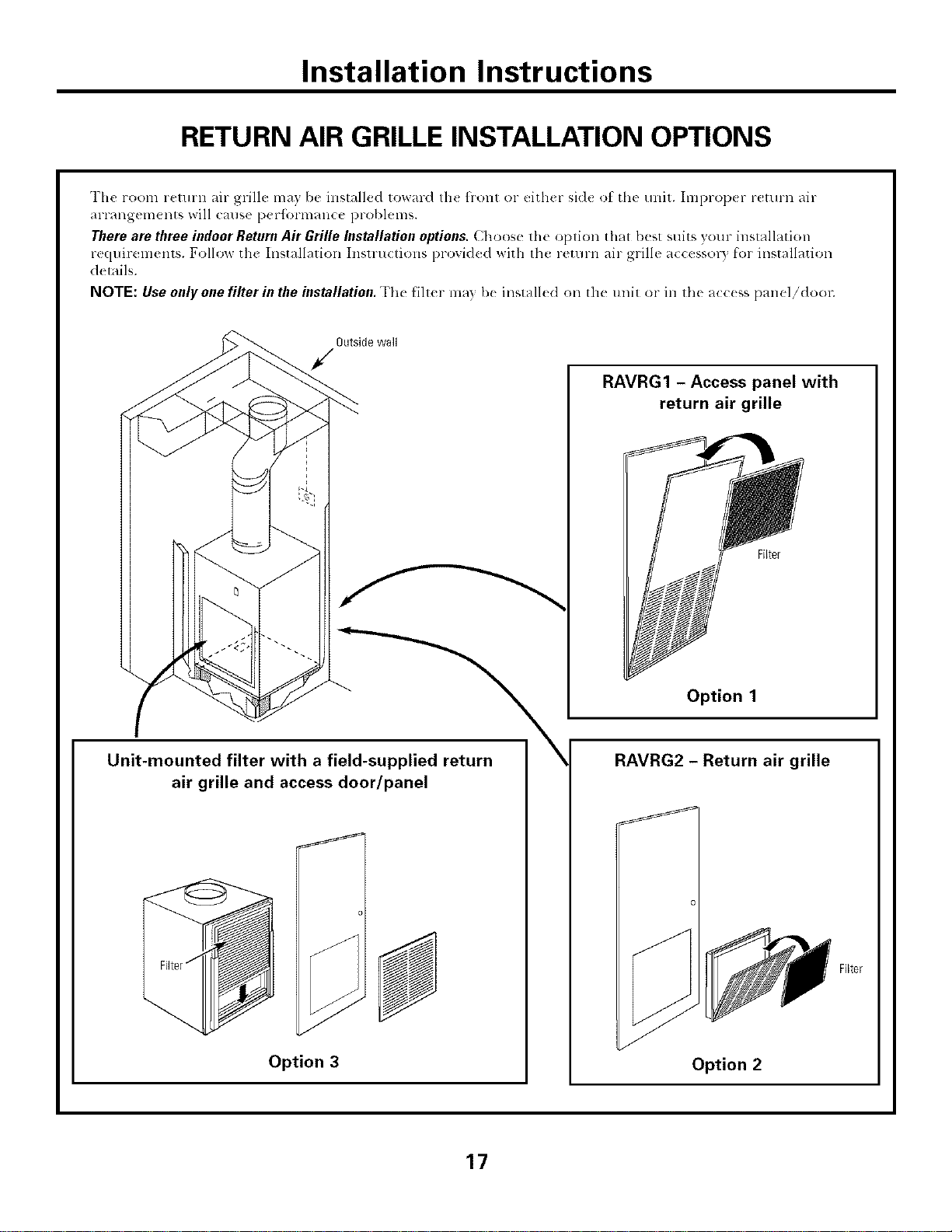
RETURN AIR GRILLE INSTALLATION OPTIONS
The room return air grill{: ma) be installed toward th( flont or either sid{ ot the unit. Improp_ r return air
arrangements will canse peHbrnaance problems.
Therearethree indoor ReturnAir Grille Installationoptions.Choose the option that best suits your hlstallation
rcquirelm,nts. Follow the Installation Instru(tions provided with the return air grille a(cessor) I_'orinstallation
details.
NOTE: Use only one filter in the installation. The Hll(r may I)< installed on th_ unit or in lb( a((<ss panel/dool:
Outside wall
Unit-mounted filter with a field-supplied return
air grille and access door/panel
J
Option 3
\
RAVRG1 - Access panel with
return air grille
Option 1
RAVRG2 - Return air grille
Option 2
17
Installation Instructions
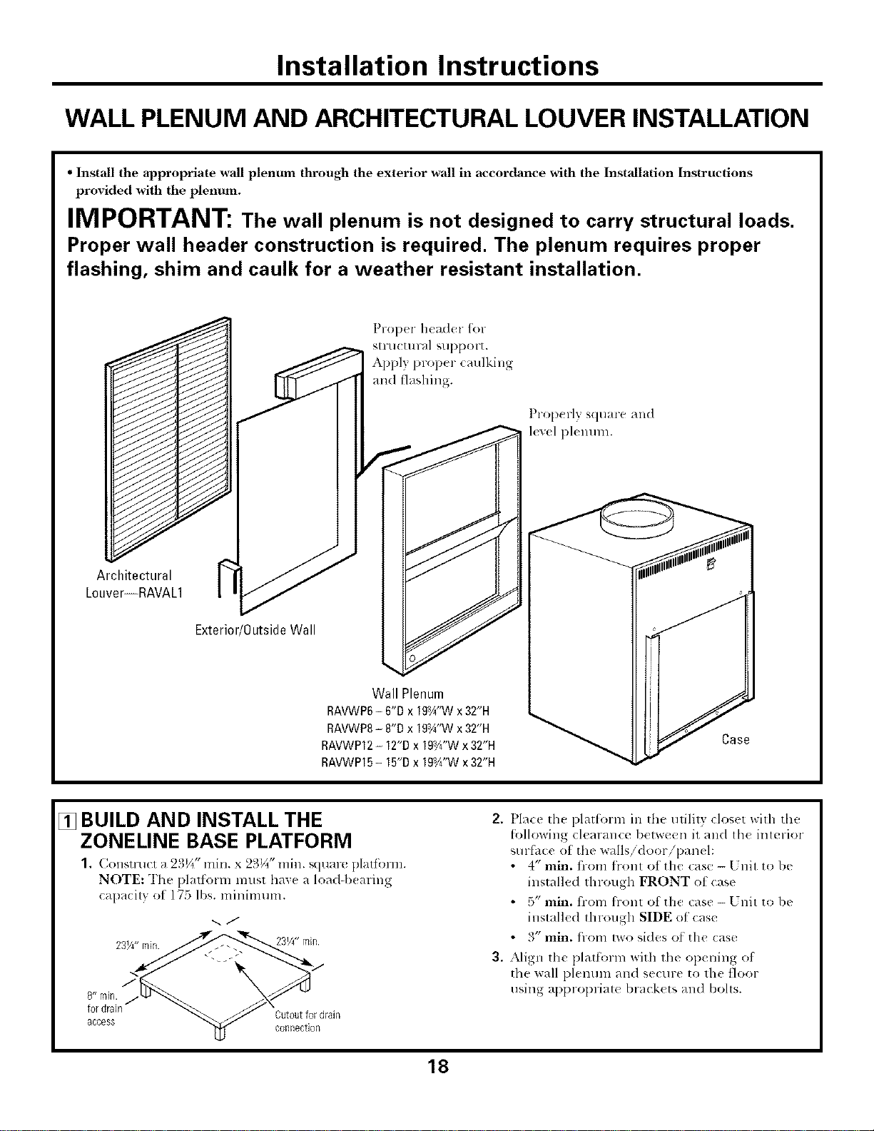
WALL PLENUM AND ARCHITECTURAL LOUVER INSTALLATION
• Install the appropriate wall plentma through the exterior wall in accordance with the Installation Instructions
provided with the plenum.
IMPORTANT: The wall plenum is not designed to carry structural loads.
Proper wall header construction is required. The plenum requires proper
flashing, shim and caulk for a weather resistant installation.
Proper header for
stru(tu ral support.
Apply proper (mdking
and fl_lshing.
Prop( fly square and
level plenum.
Architectural
Louver--RAVAL1
Exterior/OutsideWall
Wall Plenum
RAVWP6- 6"D x 19a¼"Wx32"H
RAVWP8- 8"D x 19aA"Wx32"H
RAVWP12- 12"Dx 19Vd'Wx 32"H
RAVWP15- 15"Dx 19Y¢"Wx32"H
Case
[] BUILD AND INSTALL THE
ZONELINE BASE PLATFORM
(,o sr ( r ; 2 _/_ n . x 2_)V_*'rain. square platfbrm.
NOTE: The platform must haxe a load-b(aring
capa(ily ot 175 lbs. mininaum.
2 ._j
access t4J
fordram Cutoutfor drain
n
2. Place lh( platform in the utilily closet with the
[bllowing clearance between it and lh( inlerior
surfhce of the walls/door/pan(l:
• 4" rain. fi-om flont of the case - Unit to be
installed through FRONT ot case
• 5" rain. fi-om flont of the case - [ 7nit to be
installed through SIDE of case
• 3" rain. fi-om two sides o_ the case
3, Align the platform with lh( op(ning of
the wall plenum an(1 s(cure to rile floor
using appropriate brack(ts and bohs.
18
Installation Instructions
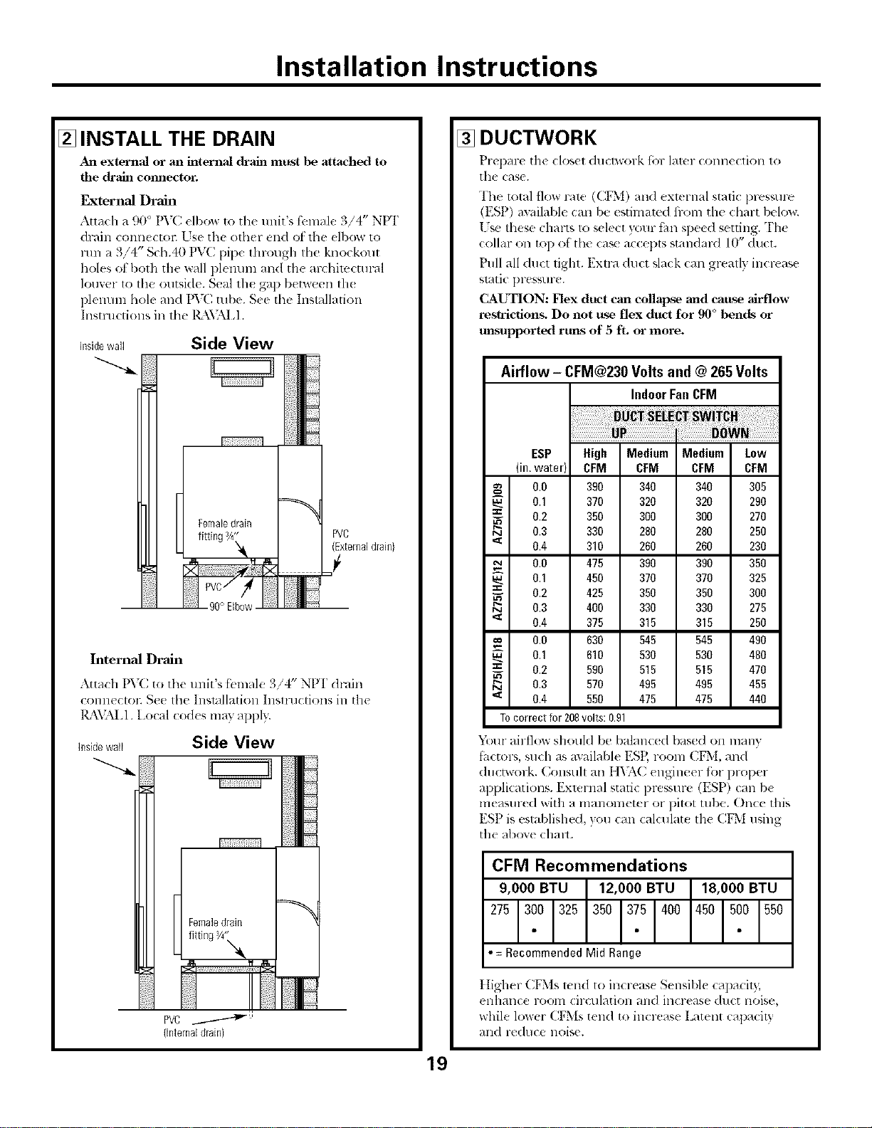
[] INSTALL THE DRAIN
An external or an internal chain must |xe attached to
the ch"ain connector.
External Drain
Attach a 90 ° PV(: elbow to tile unit's fbmale 3/4" NPI'
drain connectol: Lse the other end of the dbow to
1/111a 3/4" Sch.40 PVC pipe through the knockout
holes ot both the wall plmmm and the archimctural
louver 1o the outside. Seal the gap between th_
plenum hole and PVC ulbe. S_e the Installation
Instructions ill the l_\'_kI,l.
Insidewall Side View
PVC
(Externaldrain}
90° Elbow
Internal Drain
Attach PVC to the tmit's ti:male 3/4" NPI" &-,tin
connectoc Se( tim ]nsmllalioll Inslluetions ill tile
IL\VALI. Local cod(s may appl>:
insidewall Side View
(Internaldrain}
[] DUCTWORK
Prepare tile closet ductwork {be later connection to
the case.
The total flow role (CF*[) and exlernal static pres,,ure
(ESP) awilable can be esthnamd from tile chart below.
[ 7s*!these charts to select x_mr thn speed setting. Th_
,v
collar on top of th_ ca_ a(cepts standaM 10 duct.
Pull all duct tight. Extra duct slack can gl>atly increase
slatic pressur(.
CAUTION: Flex duct can collapse and cause airflow
re_tricfion_ Do not rtse flex duct for 90 °bends or
unsupported runs of 5 fL or more.
Airflow - CFM@230 Volts and @ 265 Volts
IndoorFanCFM
ESP High Medium Medium Low
(in.water) CFM CFM CFM CFM
0.0 390 340 340 305
0.1 370 320 320 290
_- 0.2 350 300 300 270
0.3 330 280 280 250
'_ 0.4 310 260 260 230
0.0 475 390 390 350
0.1 450 370 370 325
==
_- 0.2 425 350 350 300
0.3 400 330 330 275
'_ 0.4 375 315 315 250
oo 0.0 630 545 545 490
0.1 610 530 530 480
== 0.2 590 515 515 470
0.3 570 495 495 455
'_ 0.4 550 475 475 440
Tocorrectfor208volts:O.91
Y*_ur airflow should be balanc(d based on many
thctors, such as available ESP, room CFM, and
ductwork. Consuh all I l_:\C engineer fi'w proper
applications. External static pressure (ESP) can be
measm-ed with a manolneter or pitot tube. Once this
ESP is esta])lished, }ou can calculate tile CFM using
tile above chalt.
CFM Recommendations
• =RecommendedMidRange
] tigher CFMs rand to increas{ Sensible capaci b,
enhallce l-o(Nn cii-ct]lation an(1 it]crease duct iloise,
while lower CFMs tend to increase Latent capacit}
and rt duce noise.
19
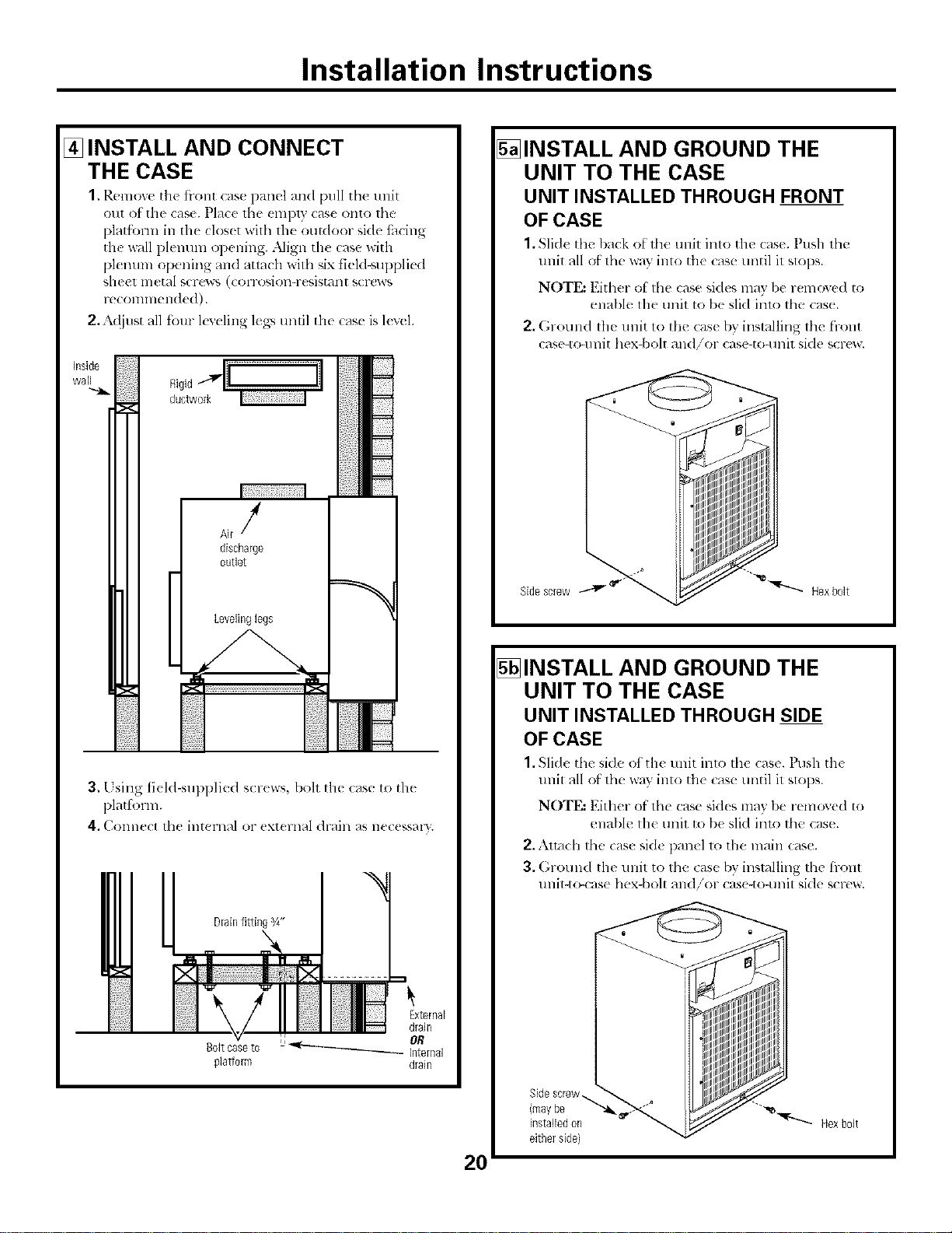
Installation Instructions
[] INSTALL AND CONNECT
THE CASE
1, Remove tile ti-ont case panel and pull tile unit
otlt ot tile case. Place the empty case onto the
platl_nn in tile clos(t wifll tile outdoor side tilcing
tile wall plemnn opening..Mign the case with
plenum opening and attach with ,,ix t]eld-supi)li{ d
sheet metal scrc'_'_ (corrosion-resistant scl*:ws
reconnnended).
2,:k({jllst all four k_,eling leA>,until th_ case is l(v(l.
J
discharge
outlet
Levelinglegs
3. Using ti(ld-supplied scr<ws, boh th( case to the
plattk_rm.
4, C<mnect th_ internal or ( Xt( l:llal ({raill ;+S e( ( KS / "_'
DrainRRingg4"
Boltcaseto
plallorm
20
5_INSTALL AND GROUND THE
UNIT TO THE CASE
UNIT INSTALLED THROUGH FRONT
OF CASE
1. Slide tht _l)_l(k of thc unit into the case. Ptlsh thc
tlnit all of tile way into tile case until it slops.
NOTE: Either of tile case sides may l)e r( mo'<e(I to
enable lhe unit to be slid inlo the cas(.
2. GrOulld the llllit to the case by installing tile front
ease-to+unit hex-bolt and/or case-to-unit side screw.
5_INSTALL AND GROUND THE
UNIT TO THE CASE
UNIT INSTALLED THROUGH SIDE
OF CASE
1. Slide tilt" side of the unit imo tilt" case. Push the
tlnit all ot the way into tile case until it slops.
NOTE: Either of tile case hides may be removed to
enable tile unit to be slid inu) the case.
2,.\lmch the cas_ si(k panel to tile main case.
3. (;rotlnd the llnit to tile case by installing tile front
unit-tr_:ase hex-bolt and/or case-to-unit side screw.
Installation Instructions
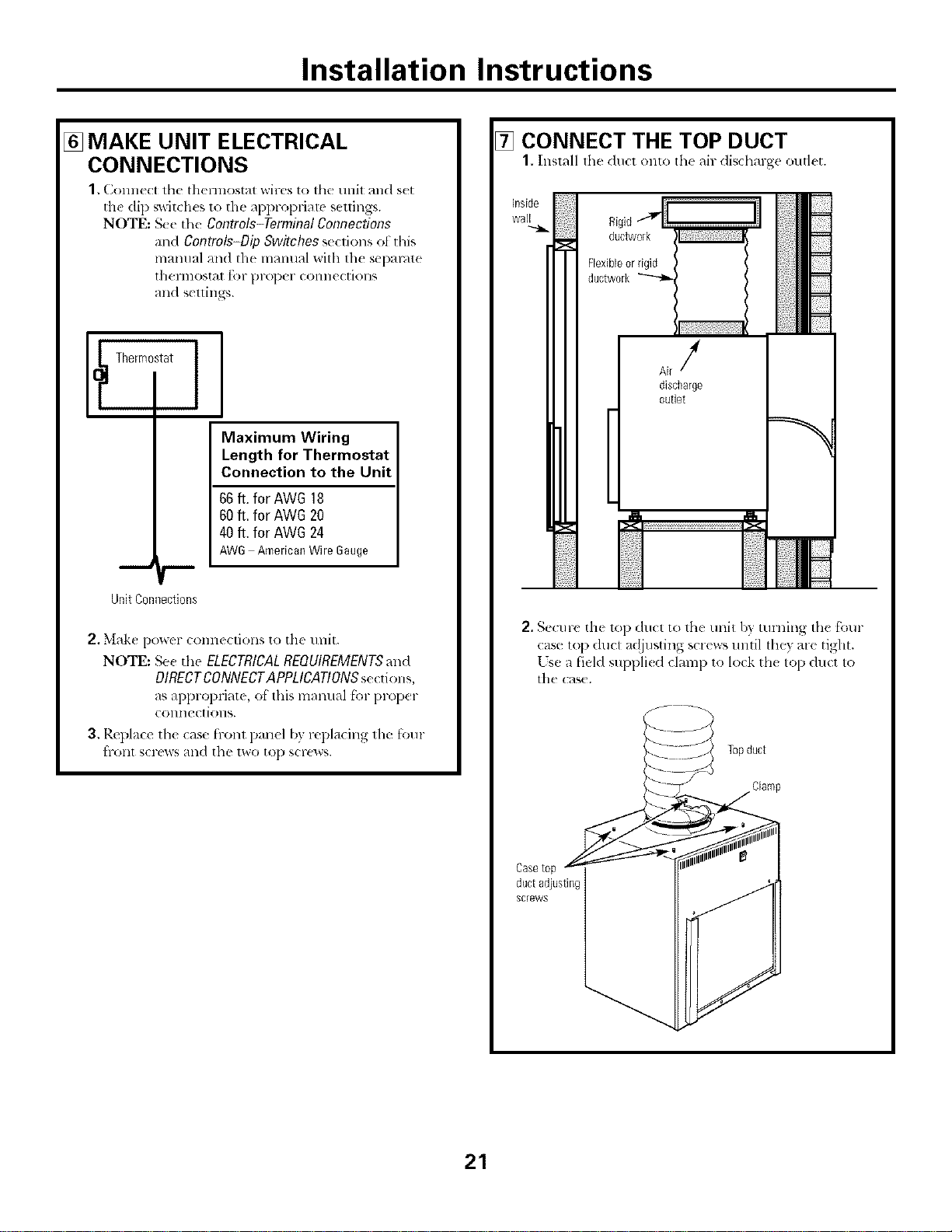
[] MAKE UNIT ELECTRICAL
CONNECTIONS
1. Conne(t tile thermostat wires to tile unit and s(t
the dip switches to the appropriate seuings.
NOTE: See tile Controls-Terminal Connections
and Controls-Dip Switches se(tions ot this
mmmal and the mmmal with th( separate
thermostat for prtq)er connections
and settings.
[_ Thermostat
I
Maximum Wiring
Length for Thermostat
Connection to the Unit
66ft. for AWG 18
60ft, for AWG20
40ft. for AWG24
AW6 AmericanWire6auge
Unit Connections
2. Make po_er connections to the unit.
NOTE: Se_ d_e ELECTRICALREQUIREMENTSat_d
DIRECTCONNECTAPPLICATIONS setdons,
as appropriatc, of this lnalltlal [_)1-pl-o[)el-
colmections.
3, Replace the case h-ont panel by replacing the [bur
hxIllt SCl'ews atld the two to[) scFews.
7_ CONNECT THE TOP DUCT
1. Install lhe du(l onto th( air disdlarge outlet.
0,g, ..................il
ductwork
Flexibleor rigid
ductwork
Air/
discharge
outlet
2. Secure the t_ l) duct to the trait b} turning the four
case top duct av!justing screws until lht T are tight.
[sea field suppli< d clamp to lock th< top duct to
the cas(.
ductadjusting
screws
21
Installation Instructions
[] FINAL CHECK
Review this Checldist bctbrc restoring po_tm
Correct line v<>hng(?
Single circuit only?
] IVACR r3pe brcakerifhse?
Ductwork (omm(ted?
Case and unit level?
Wall plenum cmllkcd? I,exel? Flashing?
Drain t onne_ted?
Wall thennostal wired con((tly?
I nit wired corre(tly?
[] CONNECT POWER
1, If nil the above items are (orve(t, mrn the po_er on
at the nl_fin smvic( i)an(l.
2. Tm-n the unit power switch, on the fl-onl ot tlle unil,
to ON b) pressing the top of the switch ill.
SERVICING
WARNING: Bef .-e
switch power off at the servic( panel and lock tile
area to prevent power trom being ',witched on
accid(ma]lv. When the area cannot be lock(d,
securely fi_sten a prominent warning device, such
as a tag, to the s( l-Gc_ l)an(l.
NOTE: _,Tesn'ongly recommend that any selMcing be
l)erfi.n-med by a (lualit]ed individual.
For ease of selxiee, tile unit call be remoxed f'rom
t]l( cHse:
1.1 nphlg 1he power cord and disconnecl th( wall
Ih( l'l]lOSI_ll ( Olllle( IiOllS.
2, Raise the top duct b) tmning all ibm- case top duct
a({justing screw_ countmvlockwise.
3. Remove the front case panel.
4. Remove tile front an(I/or side: case-to-unit
gromlding scr(_v, if present.
5. Slide tlle unit out of' the case.
22
BeforeYouCallForService... ge.com
Troubleshooting tips
Problem Possible Causes What ToDo
Zoneline does The unit is • Mak(' su re lh(' Z{melinc plug is ])ushe(1 completely
notstart unpluKge& into th( oullet.
The fuse is blown/circuit • Check tile house fuse/cir(uit/)l>aker l)ox and replace
breaker is tripped, the tilS( or r(s(t the br(ak(r.
The unit is u_aiting for • This is normal. The Zoneline will start again afler
the compressor overload it rt'sels.
protector to reset.
Power failure. • There is a prolective time delay (up to 3 nlinums) to
l)rcvent tripping of the compressor overload. For this
reason, the unit may llOt Sml-t normal heating or cooling
t_lr 3 lninutes aiier it is Hn-ned back o11.
Zoneline does notcool Indoor airflow • Make sure there arc no curtains, l)linds or furnimru
or heat as it should is restricted, blocking the air d ischmge glille or the return air grille.
Outdoor airflow is • Make suru the art hitectuml louver is not rustricm(I.
restricted or recirculated. This call Catlse the unit to (wcle ofldue to th_
COllll)l'eb_,or ox erloa(I.
• ()utdoor grille must have a minimum of 65% tree area.
Non-GE grilles may be 1oo restlictive tbr proper
l)erlbrmanc(. Consult }our salesperson fbr assismnc(.
The air filter is dirt)< • Chang( lhe tilmr at least (xelw 30 (lays.
See th{ Care and Cleaning-Air Filter section.
The room mayhave • When th( Zoneline is tiler turned on 3ou need to
been hot or cold. allow lime for the room to cool down or walm Ul).
Outdoor air is '* Set th( vent conwt)l to tile CLOSE position.
entering the room.
Burning odorat the start Dust is on the surface • This can cause a "l)urning" odor at the beginning ot
of heating operation of the heating element, the heating operation. This o(Ior should quickly fh(l(.
The air is not always The heat pump is not * This is nornml. The heat pllmp will produce warm air
cool or hot during prothmh N hot air. but not as hot as air produced when the higher-cost
operation elecuic heat is used.
The fan switdz may be • This cruises th( t_m to blow room temperature air
set at continuous fan even when the compressor or heater cycles off.
'1'11{(OlllilIIIOIlS air lllOV( i1](_111 provides b(ller
or( ralI temperatllre COlltrol.
The aft"does not feel
warm enough during
heating operation
The heat pump alone
produces air that feels
cooler than desired.
• Lse the Electric Heat Option. This t!lrlls off the
heat pump an(I warms with electric heat only.
NOTE: Use of this option will result in #Tcreasedenergy
CORSUmptioR
23
Thingsthatare normal.
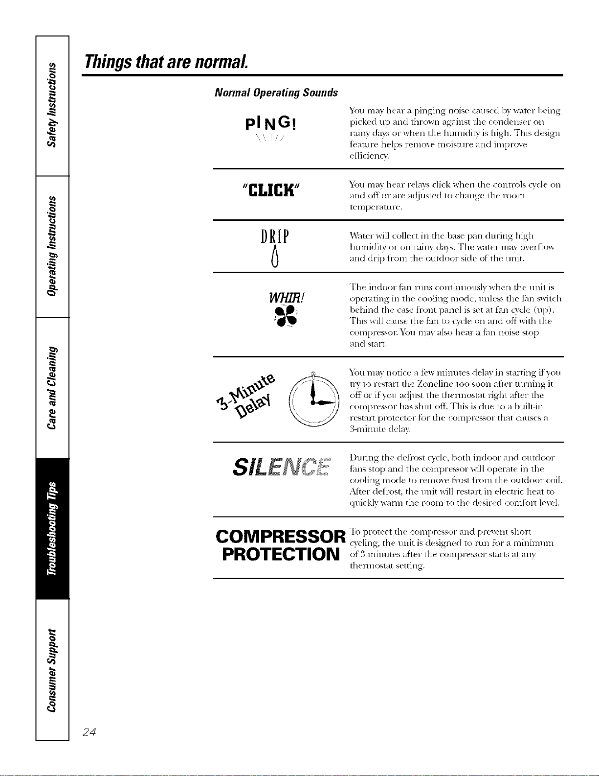
Normal Operating Sounds
PING!
Y(m may hcar a pinging noise caus¢d by water being
picked 111)and Ihrown against I11( condenser on
, rainy days or _dlen th( humidity, is high. This (h sign
/ ....
i)4/IllFe helps l'elllOV( lllOiSt/Ir( alld illll)l-OV(
efl]ci_ ncv.
tgrl[ I[rllL,,,, You may hear relays cli(k ,dmn the controls cv(l( on
blli&blri
and off or ar_ adjusted to chang( the room
tellll)el-atllr( ,
D R I P !_X_ltel ,,ill col]( (t ill the ')_lS_ l)Hll (l/IYill_ lli_h
humidity or (m rainy days. The _at(r ma? overflow
and drip from th( i)uldoor side of the unil.
WHIB!
The indoor ian l-illlS continuously wi]en the trait is
opel-tiring in th( (ooling mode, unless tile ihn s_aitch
behind the (ase tront panel is set at fhn (Tcle (up).
This will cause the thn to ode on and offwith tile
COIIIDIX'SSOI_ _'011 l]lay also Ileal a filll llOiS(! stop
and start.
You may notice a t:vw minutt s delay in starting if you
tr) to restart tile Zoneline too soon after turning it
off or if you a_ljust tile tilermostat fight after the
con]prt ssor has shut o]E "I'i]is is due to a btfih-in
l-eSt_lUt lJrol_ Ctof it)l tile COIIIpI',_!SSOI" that C_l(IS( s a
3-minute dela).
I)uHng the defi-ost cycle, both indoor and outdoor
iiuls sto[) and lhe compressor will operate in tim
cooling m_Me to remove frost from tim outdoor c41.
After deilost, the u nit will restart in electric lmat to
quickly wmm tile room to tile desired coml'cnt level.
COMPRESSOR 'Ih protec, th( coml,russor and pre, enl shorl
cycling, the unit is designed to lain f'_wa minimunl
PROTPCTION '()i o ] 11 tes lit( 111( (Ol]li)r@gsof S[_IFtS at all}
Ihel mosl_lt s( tting.
24
Please place in envelope and mail to:
General Electric Company
Warranty Registration Department
P.O. Box 32150
Louisville, KY 40232-2150
25

Consumer Product Ownership Registration
D(!ar (]ustom(tr:
"F_lkyo fl)l ) -c _s agot 1 o<lt _1< dmnkvoutbrplacingyo -_ofl]dea(einus.
xv_'(! al'( [)l-oud to hav(t you as a ctlstolller!
Follow these three steps to protect your new appliance investment:
1
Complete and mail
your t_OlISII riley
Product O_llerslfip
Registration toda)_
Ha_e th_ peace of
mind of knowing we
C41/ (onldcl (IU ill
die unlikeh' exent of a
sak'l modification,
2
Alter mailirlg the
rl gistration belong,
Stole this dociil_lel]t
i_/a sa_ place. It
you will need should
VOII I eqllJll2 St'/ViCe,
Otll ¸ service /lUll/be1 ¸ Js
800,GE,CARES
(8<t0.432.2737).
R(';td }_3tlr OwI/er's
Mamlal ca_lltllh,
It will help you
ope/ate _O/ll" nt'w
appliance prop€ fly.
Model Number Serial Number
I I I I I I I I I I I IIIIIII
Important: If you did not get a registration card with your
product, detach and return the form below to
ensure that your product is registered, or register
online at ge.com.
Consumer Product Ownership Registration
Model Number Serial Number
I I I I I I I I I I I I I I I I I
M c Ms Mls Miss
Filsl ] Lasl ]
Nml_ I I I I I I I I I Nam_ I I I I I I I I I I I I
Adlht ss I I I I I I
Apl # ] I I I I I I
I
I
I I I I I
E-m _ilAdih ess*
IIIIIIIIIII
Zip]
City] I I I I I I I I I I I I I s_me] I Code I I I I
DalePla¢¢_l
Monlh x_al Nlmll>el i I I I I I I
GEConsumer & Industrial
Appliances
GeneralElectricCompa%
Louisville, KY40225
ge,com
26
Pll ase provide your e-mMI addr* ss to recelw, via *-mail, discounts, sp_ cial ott_ls and other
important (ommunicatlt_ns from GE Appliances (GEA).
i_ Check here it_u do not wm_t to receive communicatltms from GEA's careltdly selected
pal t i/el_,,
b_\ILUI_E TO COMPLETE AND RETURN "/'ttIS CARD DOES NOT DIMINISH YOUR
For inlt>rmation about GEA's privacy and data usage pollc_ go to ge,com and click on
"PHvacy Polio" or call 800,626,2224,
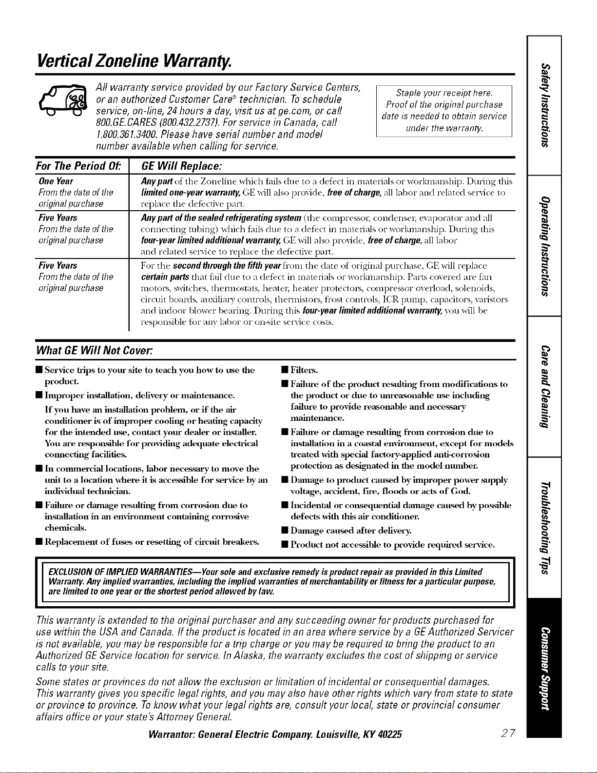
VerticalZonelineWarranty.
All warranty service provided by our Factory Service Centers,
or an authorized Customer Care®technician. Toschedule
service, on-line, 24 hours a day, visit us at ge.com, or call
800.GE.CARES(800.432.2737).For service in Canada, call
1.800.361.3400.Please have serial number and model
number available when calling for service.
Staple your receipt here.
Proof of the original purchase
date is needed to obtah7service
under the warranty.
For ThePeriod Of."
One Year
From the date of the
erighTatpurchase
Five Yeats
From the date of the
erighTatpurchase
Five Yeats
From the date of the
orighTatpurchase
GE Will Replace:
Anypartot th_ Zonclinc whid_ ik,ils du_ to _ldefb(t in malclials or workmanship. I)uring this
limited one-year warranty, GE will also provide, free of charge, all labor and rdated s_ lwicc to
r_ plac_ the dcl}.:ctive part.
Anypartofthesealedrefrigeratingsystem(Ih(t COIll[)F(SSOI_ coHdellS( I_ evaporator and all
t'onn,:,t'fing tubing) which tidls duc to a dct'_ _t in matcri_lls or workmanship. During this
four-year limited additional warranty, GE will also provide, free of charge, all labor
and relat_ d selwice to replace the defi,cfiw: pall.
For the second thraugh the fifth lear fi-.m the date of original purchase, GE will replace
certain parts that f_lil due to a defk,ct in materials or workmanship. Pal_s cow red are tm
lIIotoI%, switches, thellllO',l_ltS, l'leatel; heater lJFOlt C[OIN, c¢NnpFessor (werload, solenoids,
circuit bomds, mlxilim 3 controls, thermistors, fiost controls, ICR pump, capacitors, \v_listol_,
and indoor blow( r beming. Duling this four-year limited additional warranty, you will be
r(sponsible for ally labor or on-site sclwice costs.
What GE Will Not Cover:
• Service trips to your site to teach you how to tLse the
product.
• Improper installatiom delivery or maintenance.
If you have an installation problem, or if the ah-
conditioner is of improper coolilg or heating capacity-
for the intended use, contact your dealer or ii_staller.
You are responfflble for providitg adequate eleclrical
connecting facilities.
• In commercial locatiol_s, labor necessm'y to move the
trait to a location x_hel'e it is accessible for service hy aal
individual tedmician.
• Failm-e or damage resulting, from corrosion due to
installation in an environment contahfing corro_lve
chemicals.
• Replacement of fuses or resetthlg of ch-cuit breakers.
• Filters.
• Failure of the product resultiilg from modifications to
the product or due to unreasonable use includitig
failure to provide reasonable and necessary
maintenance.
• Failm-e or damage resulting, from corrosion due to
installation in a coastal environment, except for models
treated with spedal factory-applied anti-corrosion
protection as des_mted hi the model number.
• Damage to product caused by improper power supply
voltage, accident, ih'e, floods or acts of God.
• Incidental or consequential damage caused hy possible
defects with fltis ah- conditioner.
• Danmge caused after delivery_
• Product not accessible to provide required seiwice.
I E__LU___N_F_MPL_ED_ARRANT_ES___urs__eandexc_u_iveremedyispr_ductrepaira_pr_videdinthi_Limited I
Warranty, Any implied warranties, including the implied warranties of merchantability or fitnessfor aparticular purpose,
are limited to one Fear or the shortest period allowed bylaw,
This warranty is extended to the original purchaser and any succeeding owner for products purchased for
use within the USA and Canada. If the product is located in an area where service by a GEAuthorized Servicer
is not available, you may be responsible for a trip charge or you may be required to bring the product to an
Authorized GE Service location for service. In Alaska, the warranty excludes the cost of shipping or service
calls to your site.
Some states or provinces do not allow the exclusion or limitation of incidenta! or consequential damages.
This warranty gives you specific legal rights, and you may also have other rights which vary from state to state
or province to province. Toknow what your legal rights are, consult your local, state or provincial consumer
affairs office or your state's Attorney Genera!.
Warrantor: General Electric Company. Louisville, KY 40225
27

ConsumerSupport.
%.___________J
GEAppliancesWebsite
ge.com
] lave a queslion or need assismnc_ _dlh your appliance? "I)y lh_ GE Appliances Websile 24 houe, a (la?,
any day ot the year! For grealer convenience and [_lst(1-selvi(e, you (an no_ download ()U:ll{ l-'SManuals,
()l-del- [)aF[s oF evell schedule service on-line.
ScheduleService
Expert (;E repair selvic( is only one step away fi-om youl" doon (;el on-line and schedule your selvice al
your convenience 24 hom-s any da', of the year! Or call, Ot).GL.(_:M_I-£ (800.432.2 ,':,,_) dtll-lng normal
/)llSillesg boil l-S.
ge.com
RealLifeDesignStudio
ge.com
GE supports the [ niw psal I)esign con( epl--1)r_×luct% selvices and enxironments that (an 1)eused bx
people of all ages, sizes and capabililies. ',_k' recognize the need to design tot a wide range of physical and
mental abilities and impainnenls. For details of GE's Univel_,al I)esign applications, including kitchen
design ideas tot people with disabilities, ch_ck out our Wcbsite tt)da}. For the hearing impaired, please <:all
800i['DD.GF.\C (800.833.4322).
PartsandAccessories
ge.com
Individuals qualifi(d to s< _vi(_ Ih(ir own apl)lianc{ s can have parts or accessolies s(nt directly to their
holll( S (\r[NJ\, MasterCard and Discover (ards at(accel)t(d). ()in(l( 1-on-line Ioday, 24 hours <-_e_T day or by
pllolle _1[800.1)2(5.2002 during normal busin(ss hours.
Instructions contained in this manual cover procedures to be performed by any user. Other servicing generafly
should be referred to qualified service personnel. Cautionmust be exercised, since improper servicing may cause
unsafe operation.
ContactUs
ge.com
It)ou ar( llOt satisfi((1 with the sel'dce you receixe from GE, COlltactt/s oil ollr _,gebsite with all the details
including )our phone lmmbe_; or write to: Genel-dl Manag( l; Customer Relations
GE Appliances, Appliance Park
Louisville, IxA'40225
RegisterYourAppliance
Register yotlr new appliance on-line---at your convenience! Tim(ly l)roduct registmti_m will allow for
( llh_ll(ed (Ollll)lllllicalioll all(I [)l-Olnl)[ Sel-vicu llll(lel- th_ [ell_ls ot }'Ollr "_al-l-_lll}, should lhe ll_ ('d _llis_.
_I_)/Iln_ly also mail ill the 1)r(-print( d regislralion (ard in( hlded in die pa(ldng malelial.
ge.com
Printed in China