Loading ...
Loading ...
Loading ...
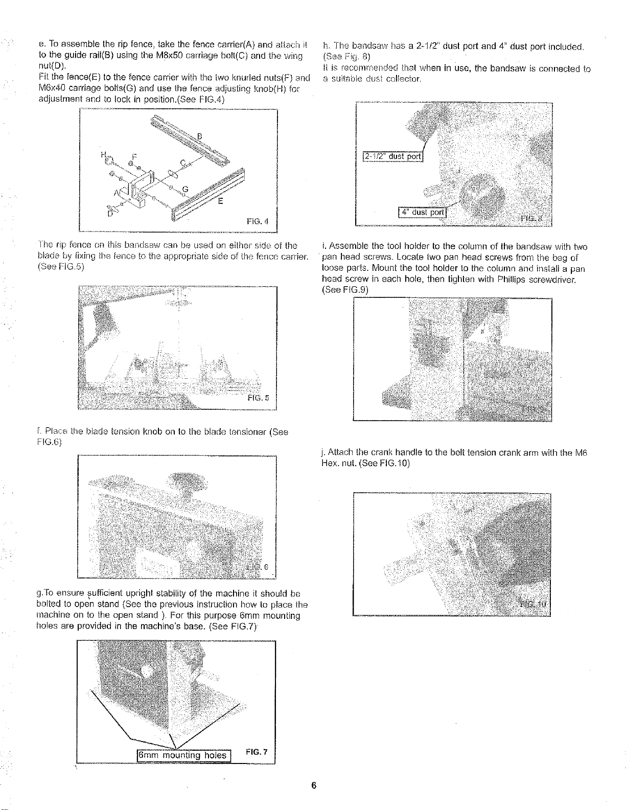
e.Toassembletheripfence,takethefencecarrier(A)andattachit
totheguideraiI(B)usingtheM8x50carriagebolt(C)andthewirlg
net(D).
Fitthefence(E)tothefencecarrierwiththetwoknurlednuts(F)end
M6x40carriagebolts(G)andusethefenceadjustingknob(H)for
adjustmentandtolockinposition.(SeeFIG.4)
FIG. 4
Ihe tip fence on this baedsaw can be used on either side of the
blade by tixing tim fence to tbe appropriate side of the fence carrier.
(See FIG.5)
[. P!ac_ the blade tension knob on to the bIade tensioner (See
FG6)
g.To ensure sufficient upright stability of the machine it should be
bolted to open stand (See the previous instruction hew to place the
rnachine on to the open stand ). For this purpose 6ram mounting
holes are provided in the machine's base. (See FIG.7)
o _, _ !!_ _F¸_ _
[6mm mounti0_gho_- FIG.7
h. The bendsaw has a 2-I/2" dust port and 4" dust port included.
(See Fig. 8)
it is recommended that when in use, the bandsaw is connected to
a suitable dusi collectoL
[2-1/2" dust port
i. Assemble the tool holder to the column of the bandsaw with two
pan head screws. Locate two pan head screws from the bag of
loose parts. Mount the toot holder to the column and install a pan
head screw in each hoIe, then tighten with Phillips screwdriver.
(See FIG.9)
!
I
!
[
j. Attach the crank handle to the belt tension crank arm with the M6
Hex. nut. (See FIG.10
6
Loading ...
Loading ...
Loading ...