Loading ...
Loading ...
Loading ...
:_ !t4_T_AL ASSEMBLY
H_{::machine is supplied partly assembled. Prior to use, the following items have to be installed: Open stand, 2-1/2" dust port, Table, Rip
Fa_co, Blade Tension Knob, Foot I;older, and Crank handle.
W.#.RN_NG: To avoid injury, do not attempt to run or use this machine until all parts are assembled and working properly.
a, A;:;sernbly the opea stand
- CI,eck contents against the parts list.
- Fasten fient panel on to paired legs, using hax carriage bolts, washers and hex nuts. Do not fully tighten.
Fasten side panel on to front panel / paired legs assemblies using remaining hex carriage bolts, washers and hex nuts.
•- Fasten the front and side beams on the paked legs with hex carriage bolls, washers and hex nuts.
- Set stand in an upright position, whilst ensuring that the holes on the top edge of the panels line up sufficiently to al!ow hex head
screws to pass through, lighten fuity the hex carriage bolts and hex nuts.
Press lubber feet on to the end of stand legs.
With assistance lift bandsaw and carefully position in place on top of stand.
- :qx iu position using hex head screw, through washer, bandsaw base, stand, washer and secure on underside with hex nut. Repeat
procedure for all four corners before tightening flJily
%t&iXNING: tb/',void back'injuw, get help lifting the bandsaw Bend your kness, lift with your legs, not your back.
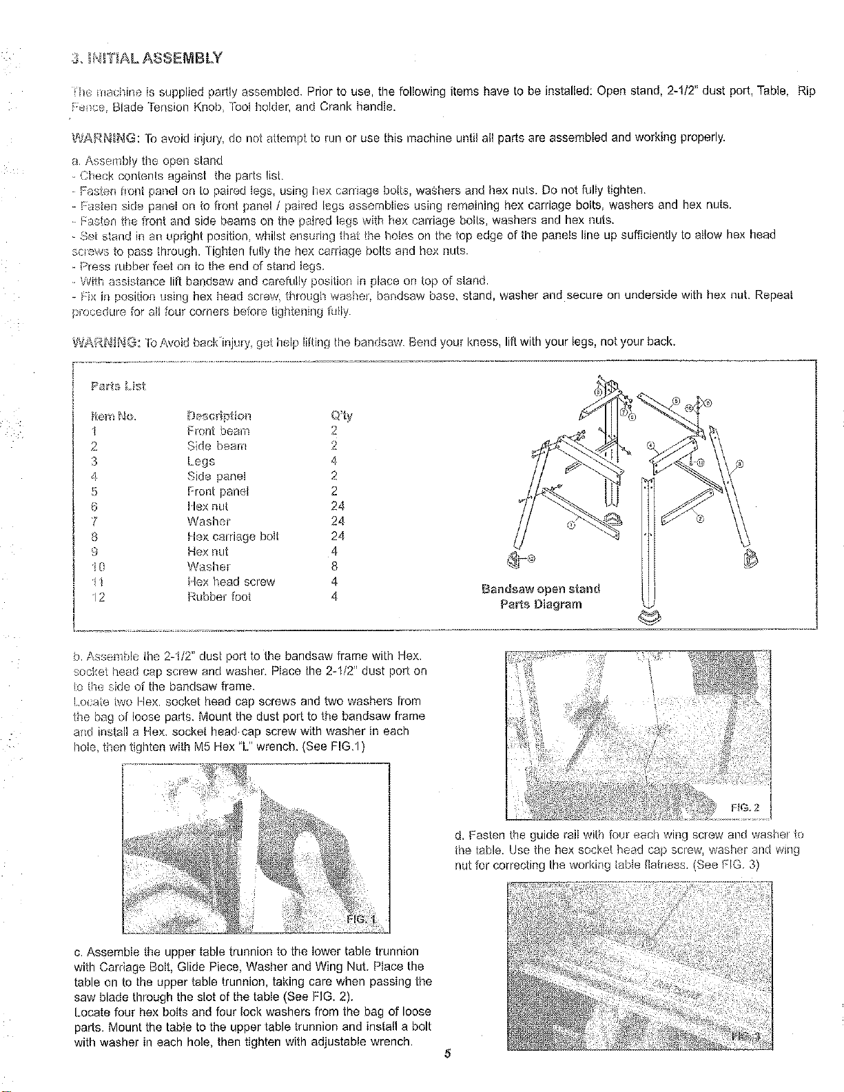
Pa_rts_ist
_te[_iNo. Descriptie_l Q'ty
I Front beam. 2
2 Side beam 2
3 Legs 4
4 Side panel 2
5 Front panel 2 "1'1
6 Ilex nut 24
ji
7 Washer 24
8 H,excarriage bolt 24
9 Hex nut 4
i 0 Washer 8
/1 'lex head screw 4
12 Rubber foot 4 Bandsaw open stand
Parts Diagram
@
b, Assemble the 2-1/2" dust port to the bandsaw frame with Hex,
socket head cap screw and washer. Place the 2-1/2" dust port on
to the side or the bandsaw frame.
Locate two Hex. socket head cap screws and two washers [rein
the bag of loose parts. Mount the dust port to the bandsaw frame
and install a Hex. socket head cap screw with washer in each
hole then tighten with M5 Hex "L" wrench. (See FIG,l)
d. Fasten the guide rail with four aach wing screw and washer to
the table. Use the hex socket head cap screw, weans'n"ana wtg
r_utfor correcting the working table tla/ness. (See FIG 3
c. Assemble the upper table trunnion to the lower table trunnion
with Carriage Bolt, Glide Piece, Washer and Wing Nut. Place the
table on to the upper table trunnion, taking care when passing the
saw blade through the slot of the table (See FIG. 2).
Locate four hex bolts and four lock washers from the bag of loose
pads. Mount the table to the upper table trunnion and install a bolt
with washer in each hole, then tighten with adjustable wrench.
Loading ...
Loading ...
Loading ...