Loading ...
Loading ...
Loading ...
nsta ation instructions
'I
2
3owire connections plus separate grounding connector
For use where local codes do not permit grounding through the Neutram wire.
Use approved 3--wire Power Supply Cord or a 3--wire Cable for Direct Wiring as described on page 23.
A separate I OAWG copper grounding wire is required.
Remove the terminal block cover @ate.
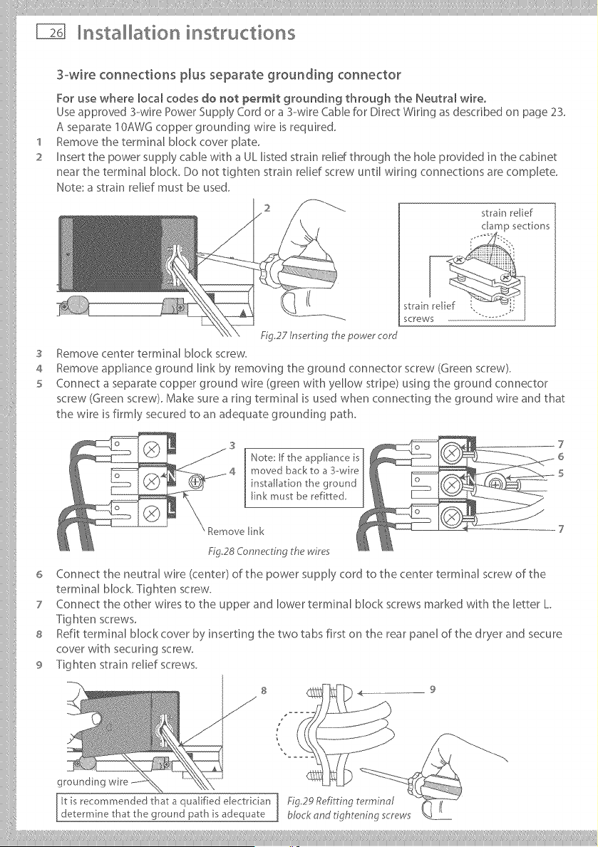
Insert the power supply cable with a UL listed strain relid through the hole provided in the cabinet
near the terminal block. Do not tighten strain relief screw until wiring connections are complete.
Note: a strain relief must be used.
strain relief
S
4
5
6
7
8
9
screws
Fig.27 In ert ng the power cord
Remove center terminal Mock screw.
Remove appliance ground link by removing the ground connector screw (Green screw).
Connect a separate copper ground wire (green with yellow stripe) using the ground connector
screw (Green screw). Make sure a ring terminal is used when connecting the ground wire and that
the wire is firmly secured to an adequate grounding path.
Note: If the appliance is
moved back to a 3-wire
installation the ground
link must be ref tted,
Remove [ink
Fig28 Connecting the wires
Connect the neutral wire (center) of the power supply cord to the center terminal screw of the
terminal block. Tighten screw.
Connect the other wires to the upper and lower terminal block screws marked with the letter L
Tighten screws.
Refit terminal block cover by inserting the two tabs first on the rear panel of the dryer and secure
cover with securing screw.
Tighten strain relief screws.
S
J
9
it is recommended that a qualified electrkian Fig29 Refitting terminal
determine that the ground path is adequate block and tightening screws
Loading ...
Loading ...
Loading ...