the
in must be
followed to minbnize the .risk of fire or
--\VHAT TO DO IF YOU SMELL GAS
° Do not try to light any appliance°
÷ Do not touch any electrical switch_ do
not use. any phone _oinyour°....building.
÷ Clear the room> baddmg or area o_ all
occapaatso
÷ Immediately call your gas supplier from
a neighbors phone° Follow the gas
supplier's instructiOnSo
÷ If you cammt .reach your gas supplier,
call the fire departmemo
must be
per_brmed by a qualified installer, service
agency or the gas supplier°
The Governor of California is required to publish a [[st of substances known to the
state of California to cause cancer or reproductive harm and requires business to
warn customers of potential exposures to such substances,
WARNING!: Gas appliances contain or produce substances, which can cause death,
or serious illness arid which are known to the State of California to cause cancer,
birth defects, or other reproductive harm, To reduce the risk from substances in
fuel or from fuel combustion, make sure this appliance is installed, operated, and
maintained according to the manufacturers [ns'truct[ons,
ntroduction
_mportantsafetyinstructions
_nstaHationinstructions
Thefirsttimeyouturnyourdryeron
Gettingstartedquickly
Operatinginstructions
Sortingandloading
Lintbucket
Selectingacycle
Wrinkleflee
Selectingthedryingprocess
Auto Sensing
Time Dry
Selecting the dryness level
Stopping your dryer
Drying cycles explained
Drying special items
Q_re labels
Lid Lock
Power failure
Caring for your AeroSmart dryer
Before you call for service
If your Ae_oSm_8 dryer beeps for help
Solving operating problems
Solving drying problems
Limited warranty
How to f;et service
2
S
7
SS
S4
34
S6
36
S7
S8
S8
S9
S9
S9
40
41
42
44
46
47
47
48
49
49
50
51
52
54
SAVE THESE INSTRUCTIONS
7/_ moc/ds showr_in thi I/s_,rCuk/_moy r_o__2_oy_i/o_2/_,in c;//mork_t_,ond ore
su£>)_?c8to>c/_on£8o_-ony tiros. Forc' /rren8</_l_Ji/s<;bo'/8modd <rods/)#cilicc/8ion
sv,,';i/c;bi/ilyin y,,x/r tourist5 p/#c/s8yis£our/oc8/weSslle/isled on the 8sck <:oy_r
or <:on/0;cSy,our/oc<s/£shet& P<_ykeldes/eiq
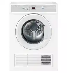
Wekome to AeroSmart
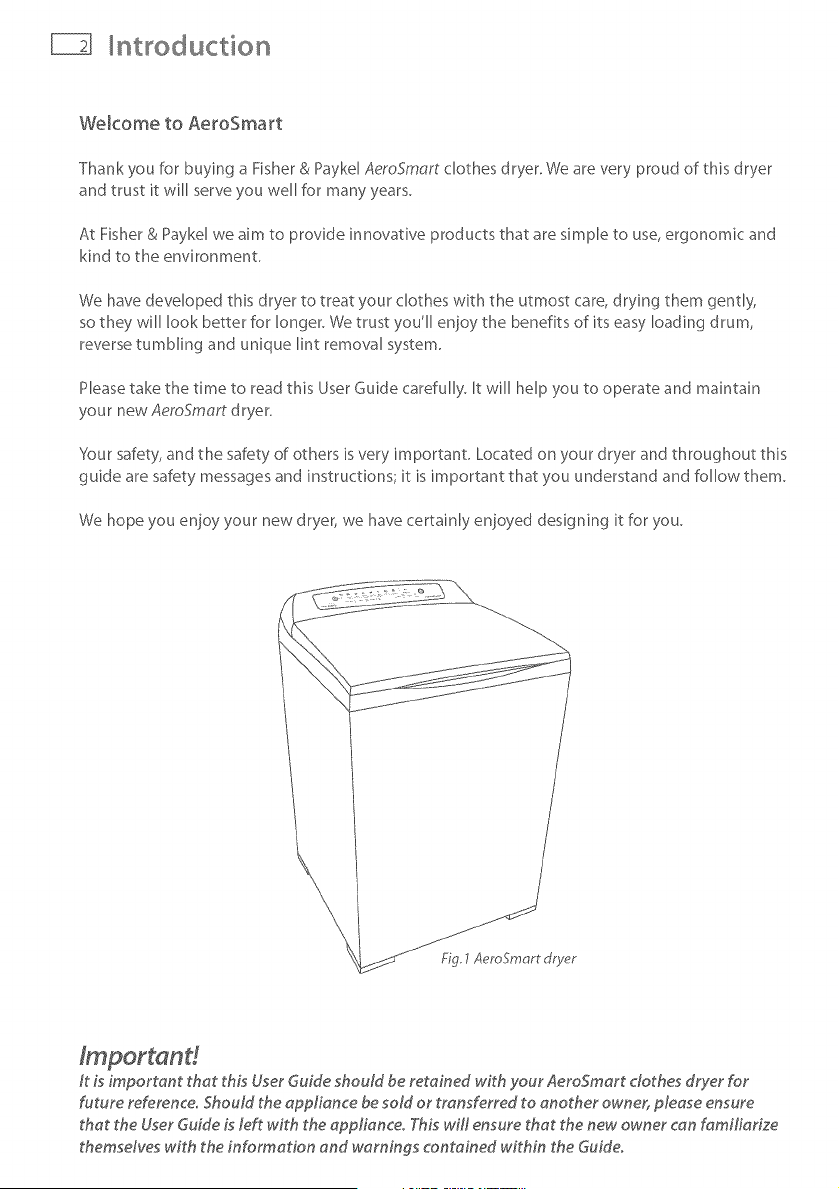
Thank you for buying a Fisher & Paykd AeroSmart clothes dryer. We are very proud of this dryer
and trust it will serve you well for many years.
At Fisher & Paykel we aim to provide innovative products that are simple to use, ergonomic and
kind to the environment.
We have developed this dryer to treat your clothes with the utmost care, drying them gently,
so they will look better for longer. We trust you'll enjoy the benefits of its easy loading drum,
reverse tumbling and unique lint removal system.
Please take the time to read this User Guide carefully. It will help you to operate and maintain
your new AemSmart dryer.
Your safety, and the safety of others is very important. Located on your dryer and throughout this
guide are safety messages and instructions; it is important that you understand and follow them.
We hope you enjoy your new dryer, we have certainly enjoyed designing it for you.
It Lsimportant that thLs User Guide should be retained w_th your AeroSmart clothes dryer for
future reference° Should the appliance be sold or transferred to another owner, please ensure
that the User Guide Lsleft with the applianceo T._Lswill ensure that the new owner can familiarize
themsdves with the information and warnings contained within the Guide.
mportant safety instructions
Symbols
SymboB will be used in this Guide to highlight when extra care is required. Abide by these at all
times to ensure you and your family are not harmed while operating your dryer.
It is important to always act with caution and use common sense when operating your dryer.
Use only as instructed by the User Guide.
This isthe saf_ty alert symbol, This symbol alerts you to hazardsthat can kill
or hurt you and others,
The saf_ty alert symbol and the word DANGERor WARNINGwill precedeall
safety messages,Thesewords mean:
YOu can be killed or seriously injured if you don't
immediate[_ follow instructions,
%u can be killed or seriously in}ured if you don't
follow instructions,
All saf_ty messageswill identify the hazard, tell you how to reduce the chance of in}ury',
and tell you what can happen if the instructions are not followed,
mportant safety instructions
Electric Shock Hazard
Follow the safety precautions outlined in this User Guide°
Failure to do so can result in death or electric shock.
Readall instructions c_refully before using this dryer.
Usethis dryer only for its intended purpose asdescribed in this Userduide_
Taminimize thep_ssibi_ity_f dectric sh_ck,unplug this dryer from the p_wer supply_r d_sc_nnect
the dryer at the householddistribution panel (byremoving the fuseor switching
off the circuit breaker) before attempting any user maintenance or cleaning,
Installations must be perf,ormedby a qualified or licensedcontractor, plumber or gasfitter qualified
or licensedby the state,province, or region where this appliance is bring installed
Thisdryer must beproperly installed and located in accordance with the Installation Instructions
her,oreit is used,
Thisdryer must beproperly grounded to conform wiP_all governing codesand ordinances,Follow
details in Installation Instructions,
Do not install or store the dryer where it will be exposedto water or exposedto the weathe,_
Connect to a properly protected, rated and sized power supply circuit to avoid electrical overload
Do not repair or replace any part of the appliance or attempt any servicing, unless specifically
recommended in the published userrepair instructions that you understand and have the skiffsto
carc¢out,
Whendisc_nnecting the dryer_pu_ by the p_ugmther than the c_rd _r_unct_n _f the c_rd _ug` t_
avoid damage to the cord orjunction of the cord plug.
Make sure the cord is located so that it will not be steppedon, tn)_pedover or otherwise subject to
stressor damage.
Do not tamper with the controls or the lid lock,
Note: Pressingthe POWERbutton doesNOTdisconnect the dryer fnom thepower supp/y:,even
though the lights are out,
Do not operate this dryer if it is damaged, malfunctioning, partially disassembledor has missing or
broken parts, including a damaged cord or plug_
Thisdryer must be directly connected to an approved fixed electrical outlet, It cannot beplugged into
an extension cord
mportant safety instructions
Fire Hazard
Only dry fabrics that have been washed with water°
Do not use heat to dry articles containing foam rubber or simHady textured
rubber.olike materiaBo Dry on the Air Dry cydeo
A clothes dryer produces combustiMe lint and must be exhausted
outdoorsoTake care to prevent the accumulation of _int around the exhaust
opening and in the surrounding area°
Do not use fabric softeners or products to e_iminate static unless
recommended by the manufacturer of the fabric softener or product°
Failure to follow these instructions can result in death or personal injury°
To reduce the risk of fire in a tumble dryer the fo
Important safety insWuctions
Do not reach into the appliance if the drum is moving.
Close supervision is necessary if this dryer is used by or near children. Do not allow children to
play inside, around or with this dryer or any other appliance.
Never cNmb on, climb into, or stand on the dryer top, lid or drum.
Undergarments that contain metal reinforcements should not be placed directly in the dryer.
Damage to the dryer can result if the metal reinforcements come loose during drying.
The intedor of the appliance and exhaust duct should be cleaned periodically by qualified
servke personnel
Before the appliance is removed from servke or discarded remove the lid and the drum door to
the drying compartment.
SAVE INSTRUCTIONS
_nsta_ation instructions
i ! - R of fire
Cbthes dryer installation must be performed by a qualified installe_.
hstaH the clothes dryer according to the manufacturer's instructions and Ioca_ codes°
Do not install a clothes dryer with flexiMe p_astic venting materiaBo ff flexiMe meta_
(foil type) duct is installed, it must be of a specific type identified by the appliance
manufacturer as suitable for use with clothes dryers° F_exiMe 'venting materiaB are known
to collapse, be easily crushed, and trap _into These conditions will obstruct clothes dryer
airflow and increase the risk of fireo
To reduce the risk of severe inju_ or death, follow aH installation instructions°
5AVE THESE INSTRUCTION5
Read the important safety instructions on pages 3 - 6 before you start installing the dryer
Check to make sure you have all the tools and parts necessary to correctly install this appliance.
Tools required
X" nut d river or socket wrench
Phillips screwdriver
Fht--blade screwdriver
;;;;;;;;;;;;;;;;;;;;;;;
Adjustable wrench 8" or 10" (200 mm or 250 ram) for gas connections
, Pipe joint compound (pipe dope or tape) for gas pipe connections that is resistant to
LP Propane, Butane and Natural Gas (Gas models only)
Level
o Caulkinggunandcompound(for_ns_a,_ngnewe×haus_vent/
o Gloves [
o Safetyg_asses
o Knife
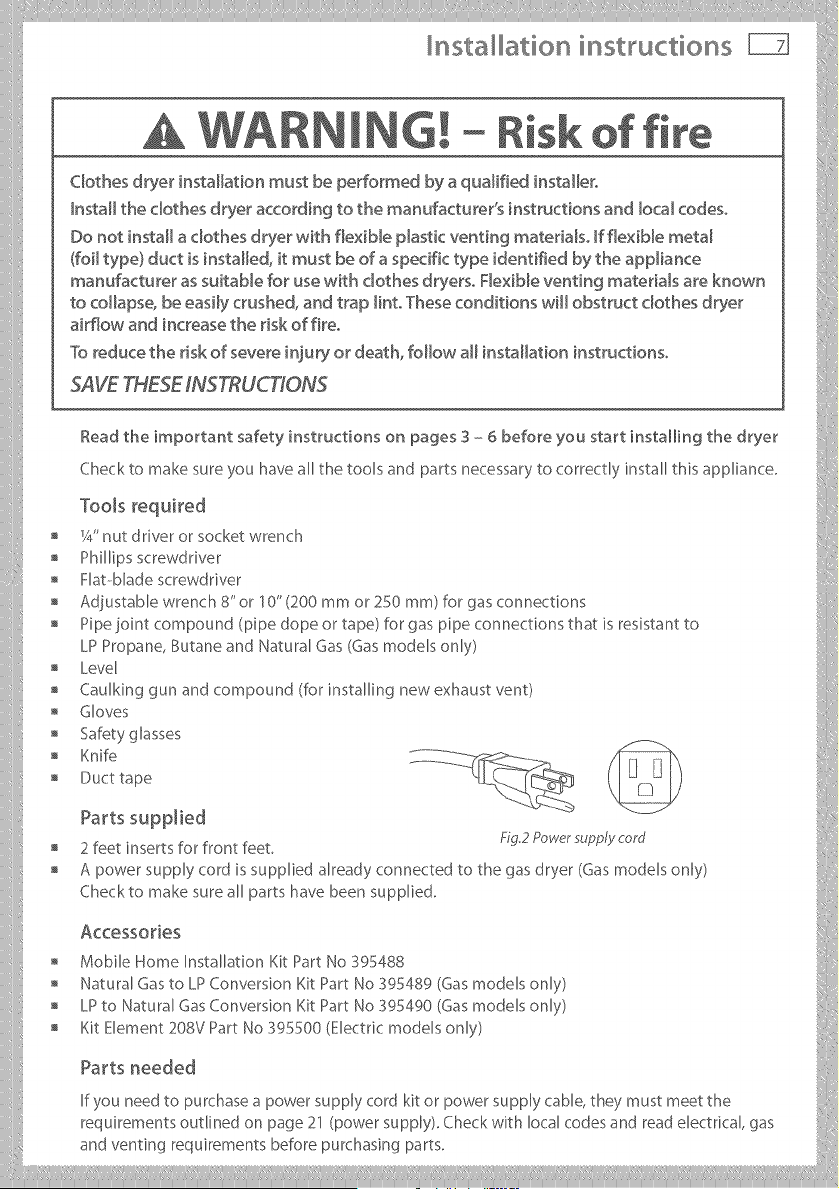
Acc÷ssories
" Mobile Home InstalhtionKitPartNo 395488
Natural Gas to LP Conversion Ki_:Part NO 395489 (Gas modeB only) ::i:
o LPtoNaturalGasConversionKitPartNoS9_490(Gasmodelsonly>
" KitElement 208V PartNo 395500 (Electricmodels only)
If you need to purchase a power supply cord kit or power supply cable, they must meet the
requirements outlined on page 21 (power supply), Check with local codes and read electrical, gas
and ventingrequirementsbeforepurchasingparts.
nsta ation instructions
To the installer
The correct installation of the dryer is your responsibility.
Be sure you read the following instructions carefully before you start to install the dryer. These
instructions should be left with the home owner for future reference.
It is your responsibility to:
Observe all governing codes and ordinances.
Check code requirements. Some codes limit or do not permit installation of clothes dryers in
garages, closets, mobile homes or sleeping quarters. Contact your local building inspector.
Adhere to these installation instructions.
Allow for spacing requirements with side by side installations (refer page 9).
Make sure you have all items necessary for correct installation.
Properly install the dryer.
Contact a qualified installer to ensure that the electrical and gas installation meets all national
and local codes and ordinances. (See page 4).
Location requirements
E×p_osion Hazard
Keep flammaMe materiaB and vapors, such as gasoline, away from the dryer,
P_acedryer at _east 18 inches (460 ram} above the floor for a garage
instaHationo
Failure to do so can result in death, expbsion, fire, or burns,
The dryer must be installed or stored in an area which is not exposed to water or weather.
It is extremely important that the dryer is installed in a well ventilated location. This dryer must
exhaust air outdoors, Do not install the dryer in any room or closet which does not permit the
free flow of replacement air.
The free area of any opening for the introduction of outside air shall not be less than twice the
area of the dryer exhaust outlet.
Before installing the dryer ensure that there is sufficient height to fully open the lid. Allow
sufficient room behind the dryer for the exhaust The air intake is at the rear of the dryer. Ensure
that there is a sufficient air passage on each side of the dryer for intake air.
Installation instructions _
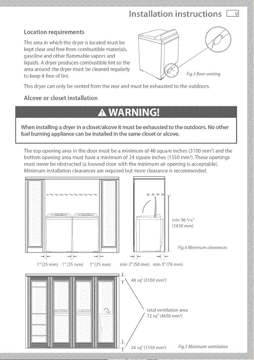
Location requkements ........ - L%_'_IA / _'%,_
The area in which the dryer is located must be __>'_" I __ ]
keptclearandfreefromcombustiblematerials, / ,J
_asol_neandotherflammablevaporsand / iq J .......
liquids. A dryer produces combustible lint so the _d ,,"""
area around the dryer must be cleaned regularly " .
to keep it free of lint F_g3 Re_r ,,,entmg .............
This dryer can only be vented from @e rear and must be exhausted to the ou@oors.
Alcove or closet installation
The top opening area in the door must be a minimum of 48 square inches (3100 mm )and the :[
bottom opening area must have a mMmum of 24 square inches (1550 mm ). These openings
must never be obstructed (a Iouvred door with the minimum air opening is acceptable).
Minimum installaqon clearances are required but more clearance is recommended. (
_ J (1430mm)
1' (25 mm) "J'(25 mm) 1"(25 mm) min 2"(50 mm) rain 3"(76 mm)
total ventilation area
nsta ation instructions
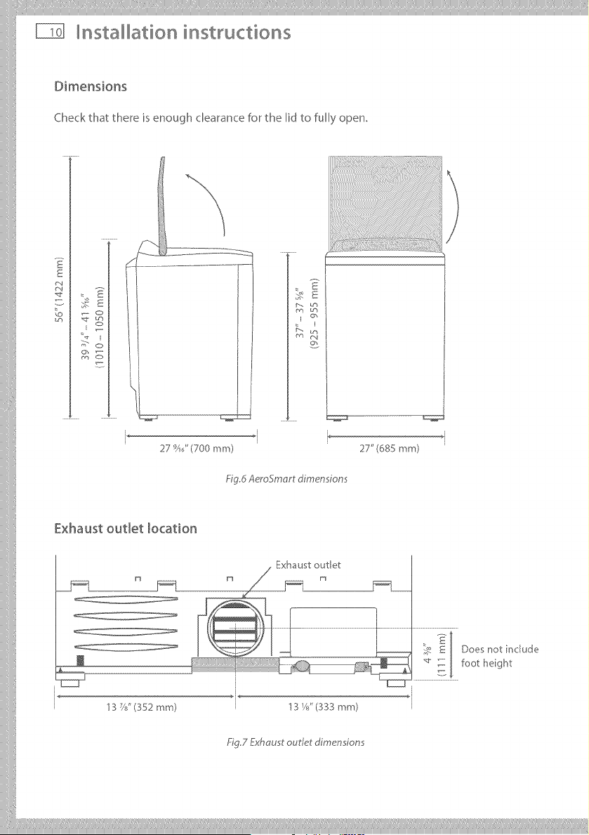
Dimensions
Check that there is enough clearance for the lid to fully open,
: E
E
/_ Lrh
O_
I
Y_ m4
°2
*i
27 _)AJ'(700 ram) 27" (68S mm)
_' g,d Aerogmart dimensions
Exhaust outlet location
n
J
13 C?'(352 mm)
. Exhaust outlet
_ E Does not include
_J .... , -_ foot height
' 3 Ys" (333 mm) l
_'g.7 Exhaust outlet dimensions
iiilI!i!,!,!!!!!' I'liiiliii,ill¸IIII IIIiiiiliill_i, iliiii_illiiillIIIlilil_ill,i!,lilii_ii!iI,lii!IIIi:liii!_iiiiii_ilill,i!_Ii!i
Installation instructions
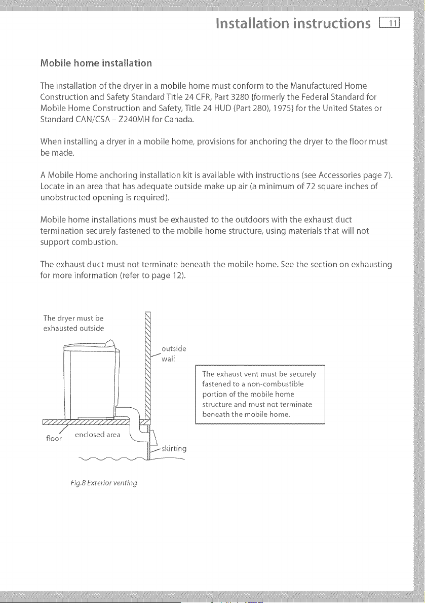
Mobile home installation
The installation of the dryer in a mobile home must conform to the Manufactured Home
Construction and Safety Standard Title 24 CFR, Part 3280 {formerly the Federal Standard for
Mobile Home Construction and Safety, Title 24 HUD (Part 280), 1975} for the United States or
Standard CAN/CSA - Z240MH for Canada.
When installing a dryer in a mobile home, provisions for anchoring the dryer to the floor must
be made.
A Mobile Home anchoring installation kit is available with instructions (see Accessories page 7).
Locate in an area that has adequate outside make up air (a minimum of 72 square inches of
unobstructed opening is required).
Mobile home installations must be exhausted to the outdoors with the exhaust duct
termination securely fastened to the mobile home structure, using materials that will not
support combustion.
The exhaust duct must not terminate beneath the mobile home. See the section on exhausting
for more information (refer to page 12).
illllllllllllllllllllll
iiiii_i[
exhausted outside
__.__ st_'ucture and must not te_*minate
/ skkt n g
___________
nsta ation instructions
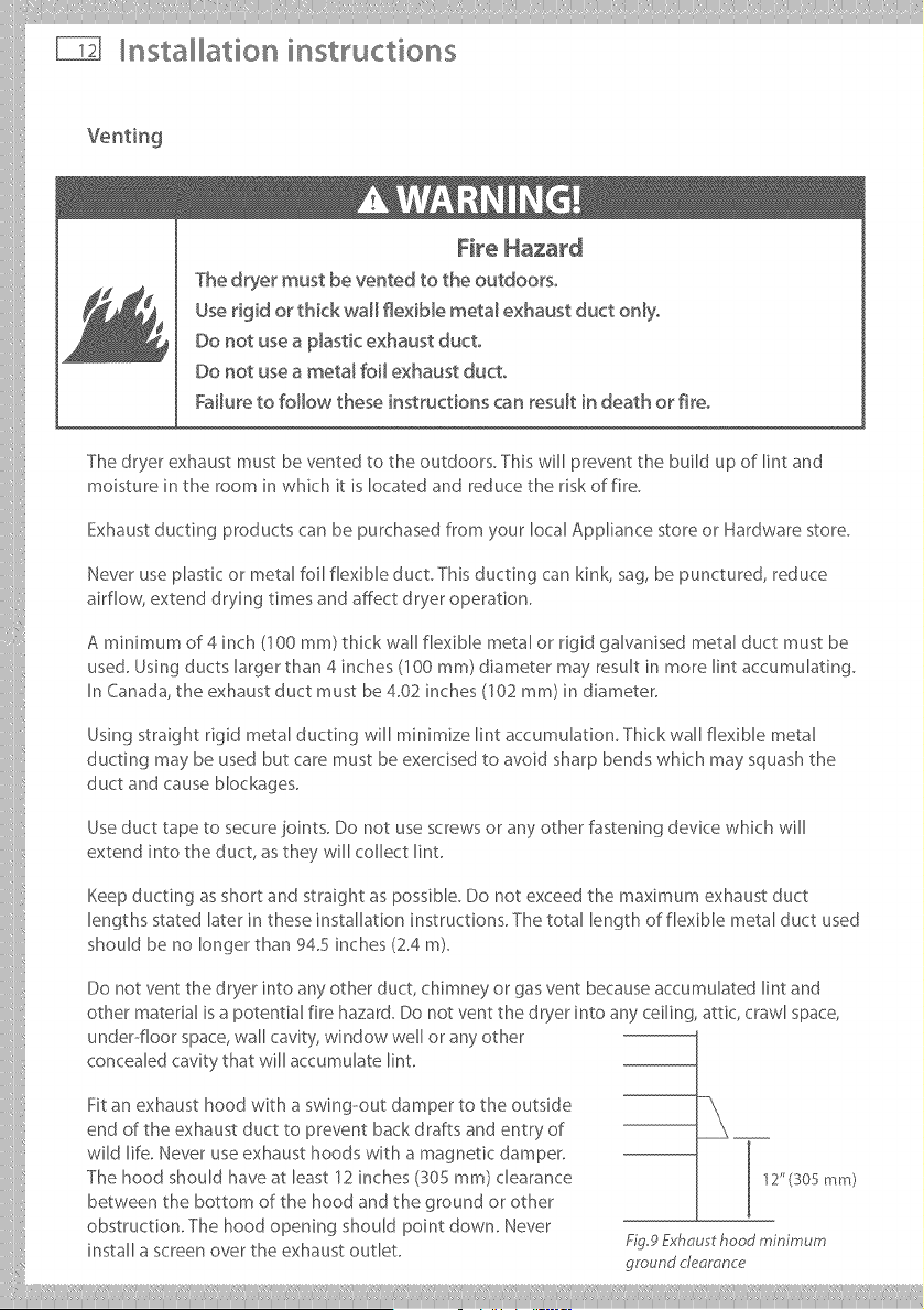
Fire Hazard
The dryer must be vented to the outdoors,
Use rigid or thick wall flexiMe meta_ exhaust duct on_y,
Do not use a p_astic exhaust duct,
Do not use a meta_ foil exhaust duct,
Failure to follow these instructions can result in death or fire,
The dryer exhaust must be vented to the outdoors. This will prevent the build up of lint and
moisture in the room in which it is located and reduce the risk of fire.
Exhaustducting products can be purchased from your local Appliance store or Hardware store.
Never use plastic or metal foil flexible duct. This ducting can kink, sag, be punctured, reduce
airflow, extend drying times and affect dryer operation.
A minimum of 4 inch (100 ram) thick wall flexible metal or rigid galvanised metal duct must be
used. Using ducts larger than 4 inches (100 ram) diameter may result in more lint accumulating.
In Canada, the exhaust duct must be 4.02 inches (102 ram) in diameter.
Using straight rigid metal ducting will minimize lint accumulation, Thick wall flexible metal
ducting may be used but care must be exercised to avoid sharp bends which may squash the
duct and cause blockages.
Useduct tape to securejoints. Do not use screwsor any other fastening device which will
extend into the duct, as they will collect lint.
Keep ducting as short and straight as possible. Do not exceed the maximum exhaust duct
lengths stated later in these installation instructions. The total length of flexible metal duct used
should be no longer than 94.5 inches (2.4 m).
Do not vent the dryer into anyother duct, chimney or gas vent becauseaccumuhted lint and
other material is a potential fire hazard. Do not vent the dryer into any ceiling, attic, crawl space,
under--floorspace,wall cavity, window well or anyother
concealed cavity that will accumulate lint.
Fit an exhaust hood with a swing--out damper to the outside
end of the exhaust duct to prevent back drafts and entry of
wild life. Never use exhaust hoods with a magnetic damper.
The hood should have at least 12 inches (S05 ram) clearance
between the bottom of the hood and the ground or other
obstruction. The hood opening should point down. Never
install a screen over the exhaust outlet.
12"(305 mm)
Fig9 Exhau t hood minimum
ground clearance
iiilI!i!,!,!!!!!,l,liiiliii,ill ¸IIII lllliiiliill,i,iliiii,illiiillIIIlill,ill,i_,lilii_ii!il,lii!lllilll,iiiiii,liiliiiiii!
Installation instructions
vo°t °g
Toreduceco.de.sat_on,_.sulatea.;,duct_._whichpassesthrough°.heatedareas.Slopethe
duct gently downwards to the hood, to drain condensation and reduce lint build up. Avoid sag
orloopsi. theductasthe!,'maycollecta.dstorewatera.daccumulateli._.
Before using an existinf_! exhaust duct system for a dryer ensure that: i i
. I,lopBticorotherpote,tiallycombustibleductorflexiblemetalfoilductinghasbeenused.
, Thedoct_s.otp_erced,k_nkedorcrushed.
o The duct does not exceed the maximum recommended lenf_lth for the new dryer.
° -[he exhaust hood damper opens and closes freely and with sufficient movement.
° Static pressure in the exhaust ducting does not exceed 1 inch of water column (250Pa), or is not
less than 0 inches of water column (ie. negative pressure), when measured with a manometer
in the d inches of the duct nearest the dryer, with the empty dryer running on Air Dry (no heat)
setting. !/:
o The exhaust duct system r'oeets all relevant local, state and national (odes.
All ducting should be inspected and cleaned at least once a )7ear to remove accumulated lint.
Frequently check that the damper on the exhaust hood moves sufficiently and opens and }
shutsfree_y.
=o ,o.oo,o
A Mobile Home Installation Kit is available (see Accessories page 7).
,°°.°°,,°.
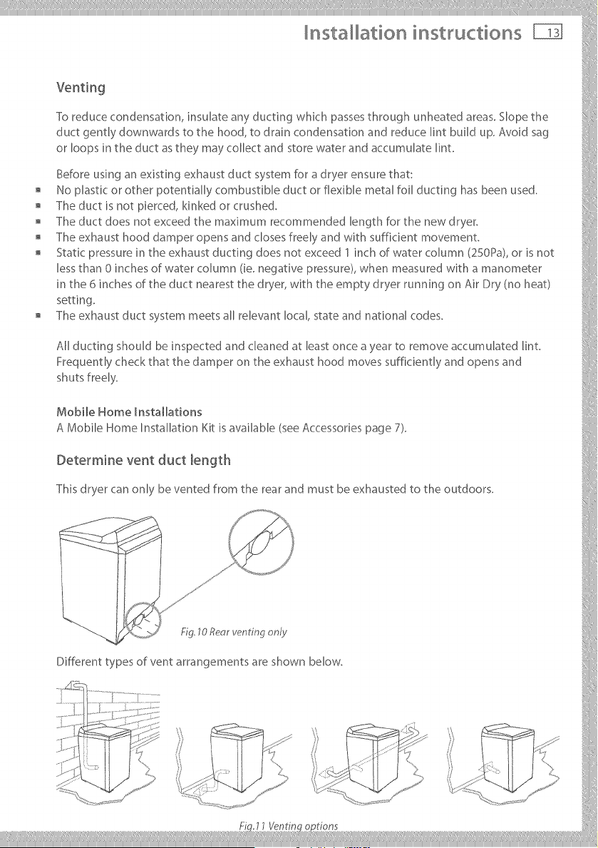
Th_sdryerca.o.lybe.e.tedfro_thereara.dmustbeexhaustedtotheoutdoors.
/ [
J ?}
/.
j" i
Different types of vent arrangements are shown below.
...... iY[,,'" "_ .... '_ .... < ', J1
......... .....<',, ,,:_B_"
K '
nsta ation instructions
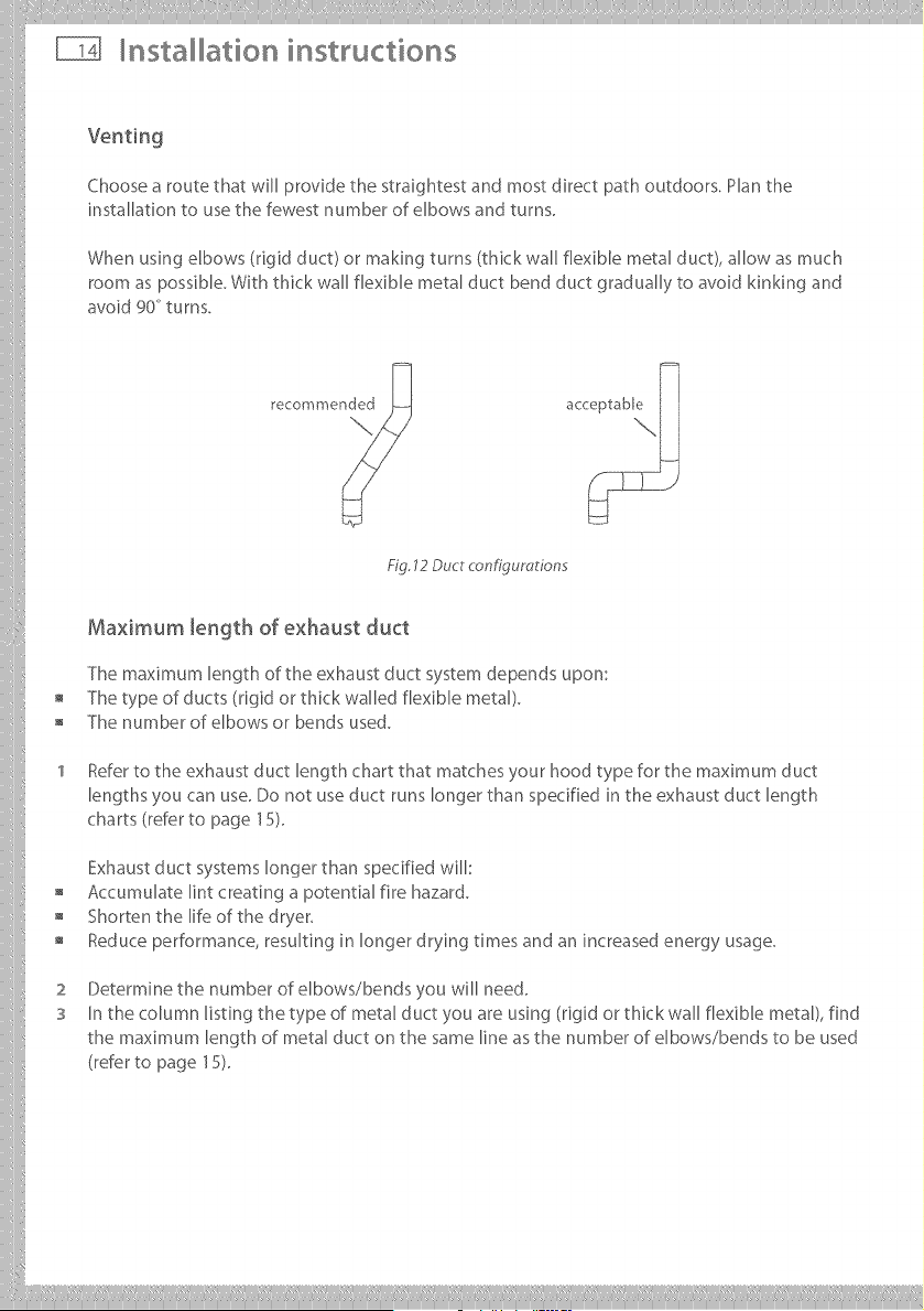
Choose a route that will provide the straightest and most direct path outdoors. Plan the
installation to use the fewest number of elbows and turns.
When using elbows (rigid duct) or making turns (thick wall flexible metal duct), allow as much
room as possible. With thick wall flexible metal duct bend duct gradually to avoid kinking and
avoid 90_ turns.
Fig. 12 Duct configurations
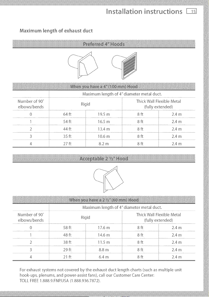
Maximum length of exhaust duct
The maximum length of the exhaust duct system depends upon:
The type of ducts (rigid or thick walled flexible metal).
The number of elbows or bends used.
Refer to the exhaust duct length chart that matches your hood type for the maximum duct
lengths you can use. Do not use duct runs longer than specified in the exhaust duct length
charts (refer to page 15).
Exhaust duct systems longer than specified will:
Accumulate lint creating a potential fire hazard.
Shorten the life of the dryer,
Reduce performance, resulting in longer drying times and an increased energy usage.
2
S
Determine the number of elbows/bends you will need.
In the column listing the type of metal duct you are using (rigid or thick wall flexible metal), find
the maximum length of metal duct on the same line as the number of elbows/bends to be used
(refer to page 15),
iiilI!i!,!,!!!!!' I'liiiliii,ill¸IIII IIIiiiiliill_i, iliiii_illiiillIIIlilil_ill,i!,lilii_ii!iI.lii!IIIi;liii!_iiiiii_
Installation instructions
Maximum length of exhaust duct
Maximum length of 4" diameter metal duct.
Number of 90 ° Thick Wall Flexible Metal
elbows/bends Rigid (fully extended)
0 64fl 19.5 m 8ft 2.4 m
1 54fl 16.5 m 8fl 2.4 m
2 44fl 13.4 m 8R 2.4 m
3 35 fl 10.6 m 8 ff 2.4 m
4 27ft 8.2 m 8ft 2.4 m
iiiiiiiiiill
_::: } }
M_×_mumlengthof4"d_mete_met=lduct
Number of 90° Thick Wall Flexible Metal
Rigid
elbows/bends : {fully extended)
..... 0...... ..................._it ...............................t:7_m.... ....................8it...........................214m....... 1
1 4Sft "_4.6m Sft Z4m
2i):t..... .... ;4 m...... .... 8it.... .... 214m.....
Fo_exhaust_;,_tem_notcove_edb;,_heexh=u_tductlengthch=_t_{_uch_ multipleunit
hook-ups, plenums, and power-assist fans), call our Customer Care Center: i
Tou_FRE_:1.sss.gmP.usA/1.88s.9:_6.;:'s;:'2/.
___________
nsta ation instructions
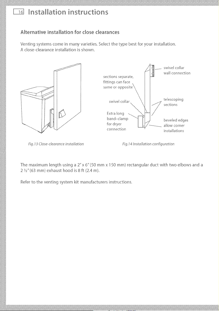
Alternative installation for dose clearances
Venting systems come in many varieties. Select the type best for your installation.
A close-clearance installation is shown.
sections separate,
f ttings can face
same or c
swivel collar
Extra long
band-clamp
for dryer
connection
swivel collar
wall connection
telescoping
sections
beveled edges
allow corner
nsta[lat[ons
Fig 13 C/ose-deomnce installation Fig. 14 Inst o/Iotion configuration
The maximum length using a 2"x 6" (50 mmx 150 ram) rectangular duct with two elbows and a
2 V2" (63 ram) exhaust hood is 8 ft (2.4 m).
Refer to the venting system kit manufacturers instructions.
iiilI!iI!i !!!_IliiiIill,illiliIIiIiiiiiIIIIIIiiiliilil!!li!liii,iliilliIliiiiiiiiiiIIilillliii,illilii_iil!l,liiIiili:liii_iiililiiiiliilili!iiiii!illiii!
Installation instructions
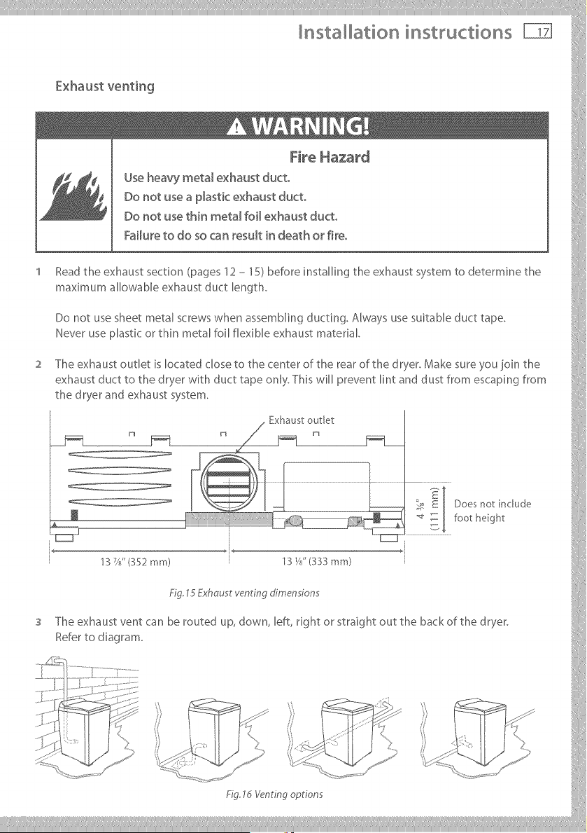
fxhtust veltilg
I 11
Use heavy metal exhaust duct
' tead the exhaust section (pages 12 - 15) before installing the exhaust system to detemqne the
maximumaUowableexhaustductlength.
Donotusesheetmetalscrewswhenassembl_n_duct_ng.Alwaysusesuitableducttape.
I,leve_useplastico_thinmetalfoUflexibleexhaustmaterial.
2 The exhaust outlet is located close to the center of the rear of the dryer. Make sure you join the
exhaust duct to the dryer with duct tape only. This will prevent lint and dust from escaping from
the dryer and exhaust system.
. Exhaust outlet :}[ .....
- t
..... _e _ [ Does not include ?7ii
_ E _: : [ footh_ght
.................... I
3 The exhaust vent can be routed up, down, left, dght or straight out the back of the dryer.
Refe_tod_ag_am. i
......._f-.....
_{:33: ....
..... " - , ' ,iM {
' \} ,,,, _ i
..... '% ; , .... ; ....
..... _:_!(': = k" ...... _'
___________
nsta ation instructions
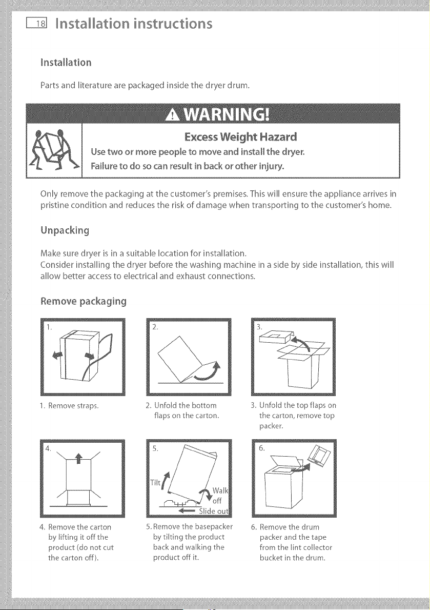
Installation
Partsand literature are packaged inside the dryer drum.
Excess Weight Hazard
Usetwo or more people to move and install the dryer,
Failure to do so can result in back or other injury,
Only remove the packaging at the customer's premises. This will ensure the appliance arrives in
pristine condition and reduces the risk of damage when transporting to the customer's home.
Make sure dryer is in a suitable location for installation.
Consider installing the dryer before the washing machine in a side by side installation, this will
allow better access to electrical and exhaust connections.
Remove packaging
1. Remove staps
4.
4. Remove the carton
by lifting it off the
product (do not cut
the carton off).
2_
2. Unfold the bottom
flaps on the carton
5 Remove the basepacker
by tilting the product
back and walking the
product off t.
3.
3. Unfold the top flaps on
the carton, remove top
packer.
6. Remove the drum
packer and the tape
from the lint collector
bucket n the drum.
Installation instructions _
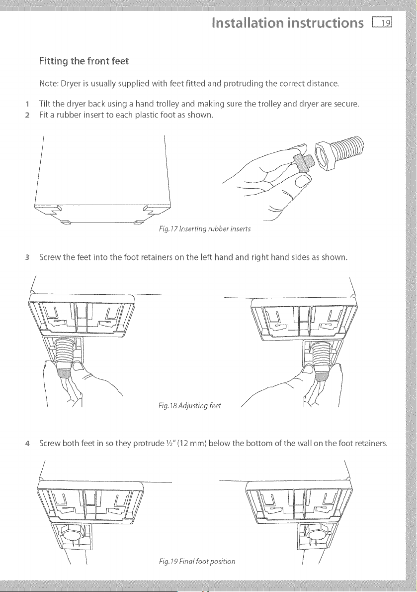
Fitting the f_or_t feet
Note:Dryerisusuall;,,suppliedwithfeetfittedandprotrudingthecorrectdistance.
1 Tilt the dryer back using a hand trolley and making sure the trolley and dryer are secure.
2 Fit a rubber insert to each plastic foot as shown.
lZ /n_rtm rubber lnsert -_ !
Screw the feet into the foot retainers on the left hand and right hand sides as shown.
_g 18Ao'jusrmgf_?er
4 Screwb_thfeet_ns_theyPr_t[udei/S(12mm)be_wtheb_m_fthewa_nthef_treta_ners_`
9 Finol foot po ii:_
___________
nsta ation instructions
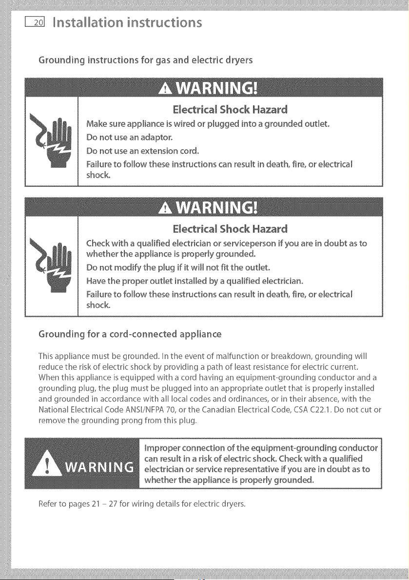
Grounding instructions for gas and electric dryers
E_ectrical Shock Hazard
Make sure appliance is wired or p_ugged into a grounded oudeto
Do not use an adaptor,
Do not use an extension cord,
Failure to follow these instructions can result in death, fire, or e_ectrica_
shock.
Electricam Shock Hazard
Check with a qualified e_ectdcian or' serviceperson if you are in doubt as to
whether the appliance is propedy grounded,
Do not modify the p_ug if it will not fit the out_eto
Have the proper out_et installed by a qualified e_ectriciano
Failure to follow these instructions can result in death, fire, or e_ectrica_
shock.
Grounding for a cord-connected appliance
This appliance must be grounded, In the event of malfunction or breakdown, grounding will
reduce the risk of electric shock by providing a path of least resistance for electric current
When this appliance is equipped with a cord having an equipment-grounding conductor and a
grounding plug, the plug must be plugged into an appropriate outlet that is properly installed
and grounded in accordance with all local codes and ordinances, or in their absence, with the
National Electrical Code ANSI/NFPA 70, or the Canadian Electrical Code, CSA C22.1. Do not cut or
remove the grounding prong from this plug.
Improper connection of the equipment-grounding conductor
can result in a risk of e_ectdc shock° Check with a qualified
electrician or service representative if you are in doubt as to
whether the appliance is property grounded°
Refer to pages 21 - 27 for wiring details for electric dryers.
iiilI!i!,!,!!!!!, I,liiiliii,ill¸IIII IIIiiiiliill,i, iliiii_illiiillIIIlilil_ill,i_,lilii_ii!iI,lii!IIIilII,iiil,i lli/iiiii!
Installation insWuctions
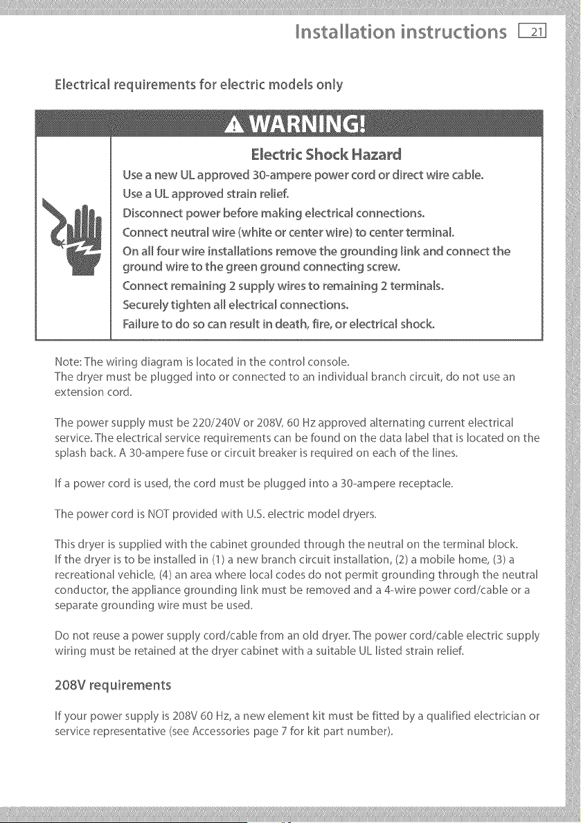
Electrical _equkements for electric models only
Fa/ u re to do so ca n result in deat h, fire, o r elect dcal shoc k,
Hote:Thewiringdisgrsmislocatedit,thecontrolconsole.
Thedryermustbepluggedintoorconnectedtosnindividualbranchcircuit,donotusesn
The power supply must be 220/240%" or 208V, 60 Hz approved alternstirKj current electrkal
servke. The electrkal service requirements car, be found on the data label that is located on the
splash beck. A 30-ampere fuse or circuit breaker is required on each of the lines.
If a power cord is used, the cord must be plugged into a 30-ampere receptacle.
The power cord is NOT provided with U.S. electdc model dryers.
This dryer is sup@led with the cabinet grounded through the neutral on the terrains, b,ock. ,:
If the dryer is to be installed in (1) s new branch circuit installation, (2) s mobile home, (3) s
recresqonsl vehkle, (4) an area where local codes do not permit grounding through the neutral
conductor, the appliance grounding Ink must be removed and a 4-wire power cord/cable or s
separate grounding ,,,,'ire must be used.
Do not reuses power supply cord/cable from an old dryer. The power cord/cable electrk supply
wiring must be retained at the dryer cabinet with a suitable UL listed strain relief.
20=vroq°iro o°
If your power supply is 208V 60 Hz, a new element kit must be fitted by s qualified electrkian or
servke representative (see Accessones page 7 for kit part number). }}
___________
nsta ation instructions
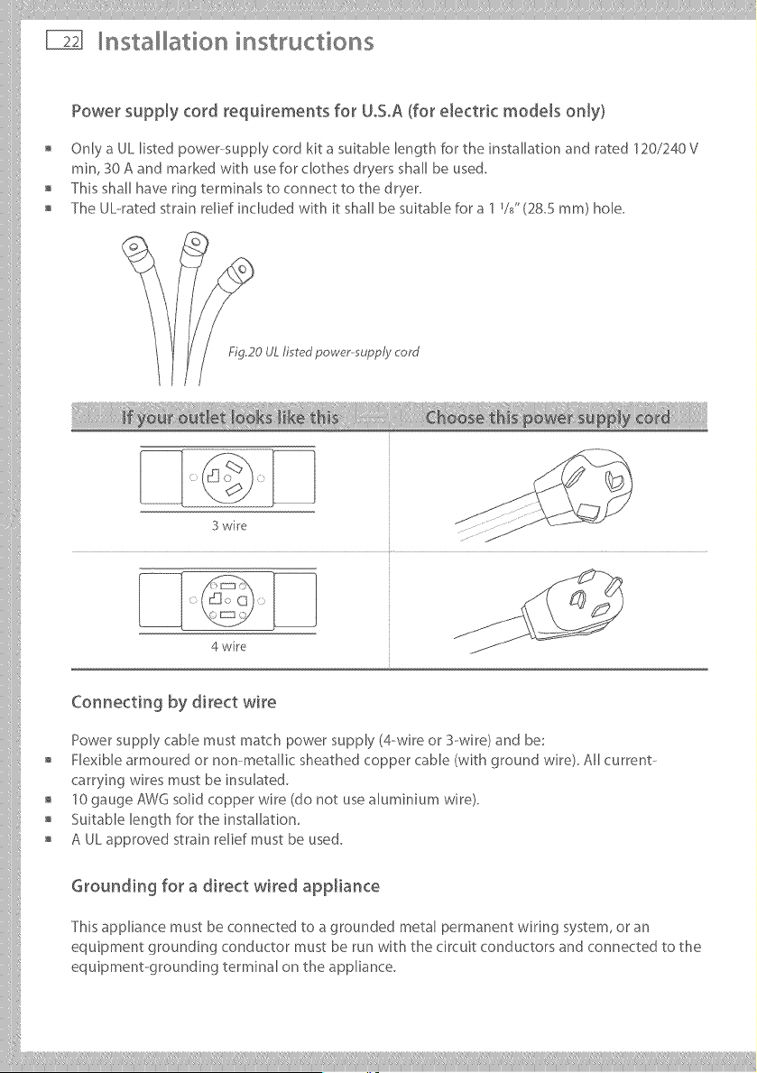
Power supply cord requirements for UoSoA(for electric models only)
Only a UL listed power-supply cord kit a suitable length for the installation and rated 120/240 V
rain, 30 A and marked with usefor clothes dryers shall be used.
This shall have ring terminals to connect to the dryer.
The UL--ratedstrain relief included with it shall be suitable for a 1%" (28.5 ram) hole.
FIG20 UL fired power-supply cord
3 wire
4 wire
Connecting by direct wire
Power supply cable must match power supply (4-wire or S--wire) and be:
Flexible armoured or non-metallic sheathed copper cable (with ground wire). All current--
carrying wires must be insulated.
10 gauge AWG solid copper wire (do not use Muminium wire).
Suitable length for the installation,
A UL approved strain relief must be used.
Grounding for a direct wired appJiance
This appliance must be connected to a grounded metal permanent wiring system, or an
equipment grounding conductor must be run with the circuit conductors and connected to the
equipment-grounding terminal on the appliance.
iiilI!i!,!,!!!!!' I'liiilii;i,ill¸IIII IIIiiiiliill_i, iliiii_illiiillIIIlilil_ill,i!,lilii_ii!iIlii[IIIi;liii!_iiil,i
Installation instructions
Electrical connections (electric models only)
Please read Electrical requirements and grounding instructions on pages 20 - 21 first°
Electric models of the dryer are manufactured for a 3--wire connection system. The dryer frame
is grounded by a link to the neutral conductor on the dryer terminal block. If local codes do
not permit grounding through the neutral, the grounding link from the terminal block must be
removed and a separate ground wire must be used.
The grounding link on the dryer must be removed for all 4-wire installations including new,
remodelled construction, or mobile homes.
These Electrical Connection instructions provide for installing the dryer in the following
situations:
3-wire connection where local codes permit grounding through the neutral.
3-wire connection plus separate grounding connector where local codes do not permit
grounding through the neutral.
4--wire connection.
Each of the above connections can be made with an approved power supply cord or by direct
widng. Each connection instruction identifies the appropriate Power Supply Cord and covers
requirements for direct widng.
For 3-wire connections by power cords
3-wire power supply cord must have three 10 AWG copper wires and match a 3-wire receptacle
ofNMEATypelOSOR.
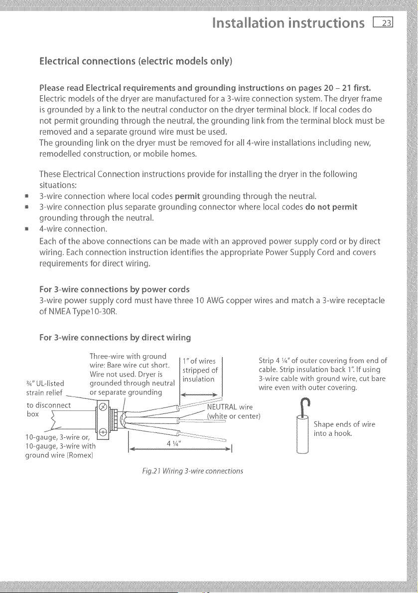
For 3-wi re con nections by di rect wi ri ng
T[]_eezwlm '!Ath g[oun! J1" of w res I Strip 4 Y/' of outer covenng from end of ,)
w re i?_a[ew_e cu_ s}qor_ stripped of cab e Strp nsu aton back 1' f usng
_, ,.. _ ._ ._ x +_. _. ÷ _ I _nsulatlon J B-wire caole with ground w_re cut bare
x4 ULqlS_.eu grounue,,_ urrougu neuda_ • _ . , '
. , _ I wre ever] wrn outer covering
strain rebel or separate grounding I._ [
box l,_,,!_teor_enter/ _ !
.... ] I Shapeendsof,._re i
0-ga ::::::- j j intoa hook.
' " ' 4 _A" _ [
0-ga I k___] :i
ground wre/_omex_ i[
@,27Wuin_3-wue_onne_r_o,:,s :'
___________
nsta ation instructions
Electrical connections (electric models only)
For 4owire connections by power cords
4--wire power supply cord must have four 10 AWG copper wires and match a 4--wire receptacle
of NMEA Type 14-o30R.The fourth wire (ground conductor) must be identified by a green cover
and the neutral wire by a white cover.
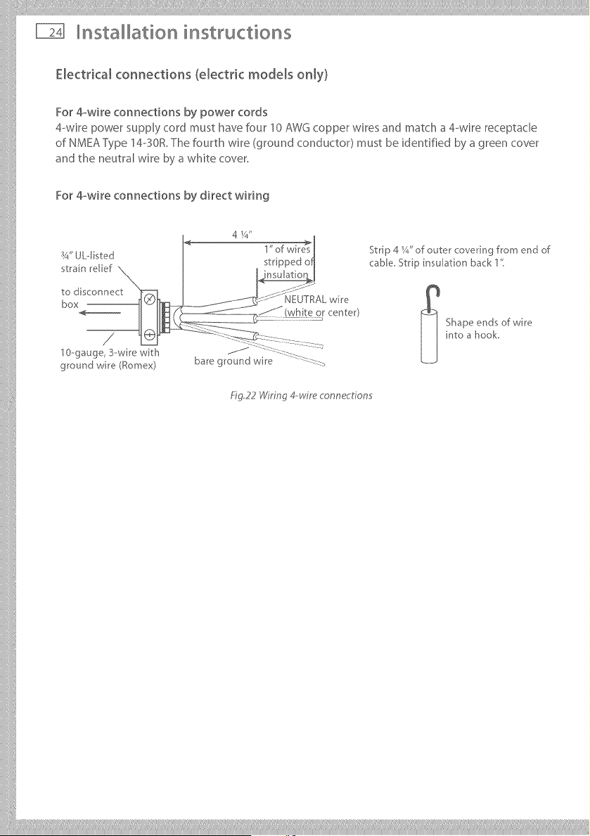
For 4-_wire connections by direct wiring
ground wire (Romex)
4 1/4"
Fig,22 Wiring 4-wire connections
Strip 4 Y_."of outer covering from end of
cable St pinsulationback1"
_ hape ends of wire
into a hook,
!!i Ii liii¸III lilill,liiiiili,i ilill li!iiilli!i!iiltii/i!
Installation instructions
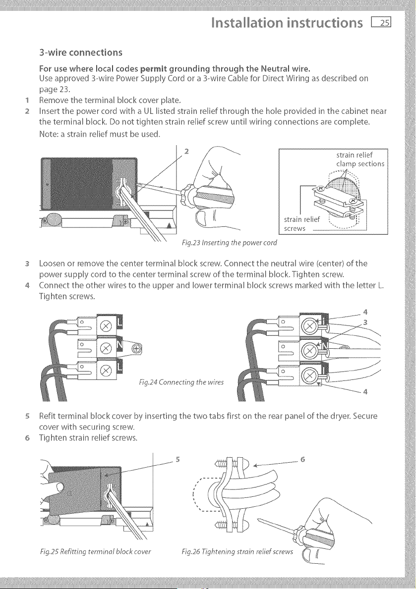
3-wke connections
Use approved 3--wire Power Supply Cord or a 3-wire Cable for Direct Wiring as described on
page 2S.
1 Remove the terminal block cover plate,
2 Insert the power cord wi@ a UL listed strain relief through the hole provided in the cabinet near }:
the terminal block. Do not tighten strain relief screw until wiring cormections are complete.
Note: a strain relief must be used. _@
,°-
@
.................................................................................Fig.23 nowe,'core/
3 Loosenorremovethecenterterminalblockscrew.Connecttheneutralwire/center/ofthe
power supply cord to the center terminal screw of the terminal block. Tighten screw,
Cor,r,ec__heotherw_resto_heupperand,owerterm_r,a,_,oc_screwsmar_odw_ththe,ether_.
Tighten screws.
4
5 tefit terminal block cover by inserting the two tabs first on the rear panel of the dryer. Secure
cover with securing screw.
6 Tightenstrainreliefscrews.
....... s _ - 6 iii
Fig 25 Refitting terminal block cover Fig2d Tightening strain relid screws
nsta ation instructions
'I
2
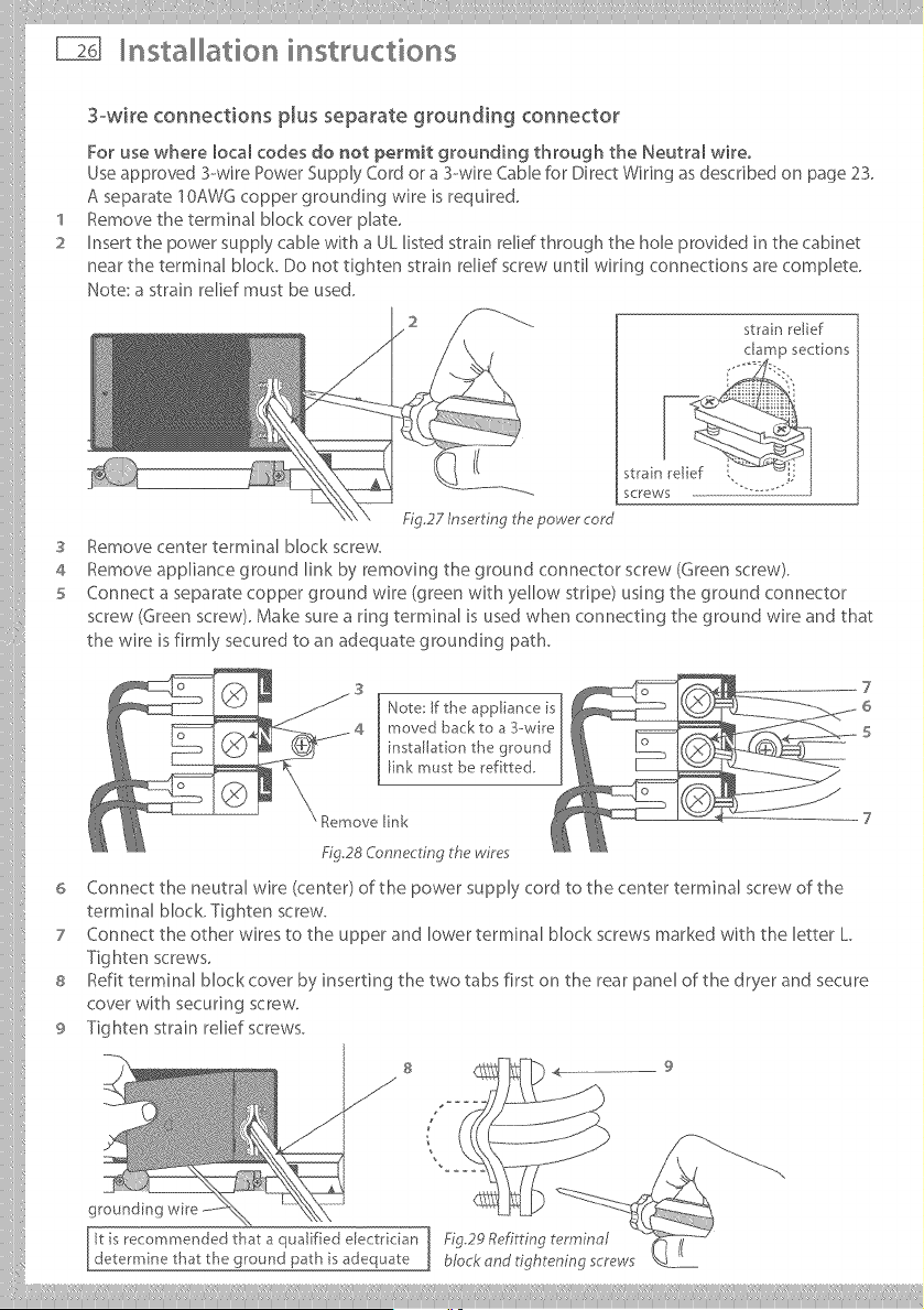
3owire connections plus separate grounding connector
For use where local codes do not permit grounding through the Neutram wire.
Use approved 3--wire Power Supply Cord or a 3--wire Cable for Direct Wiring as described on page 23.
A separate I OAWG copper grounding wire is required.
Remove the terminal block cover @ate.
Insert the power supply cable with a UL listed strain relid through the hole provided in the cabinet
near the terminal block. Do not tighten strain relief screw until wiring connections are complete.
Note: a strain relief must be used.
strain relief
S
4
5
6
7
8
9
screws
Fig.27 In ert ng the power cord
Remove center terminal Mock screw.
Remove appliance ground link by removing the ground connector screw (Green screw).
Connect a separate copper ground wire (green with yellow stripe) using the ground connector
screw (Green screw). Make sure a ring terminal is used when connecting the ground wire and that
the wire is firmly secured to an adequate grounding path.
Note: If the appliance is
moved back to a 3-wire
installation the ground
link must be ref tted,
Remove [ink
Fig28 Connecting the wires
Connect the neutral wire (center) of the power supply cord to the center terminal screw of the
terminal block. Tighten screw.
Connect the other wires to the upper and lower terminal block screws marked with the letter L
Tighten screws.
Refit terminal block cover by inserting the two tabs first on the rear panel of the dryer and secure
cover with securing screw.
Tighten strain relief screws.
S
J
9
it is recommended that a qualified electrkian Fig29 Refitting terminal
determine that the ground path is adequate block and tightening screws
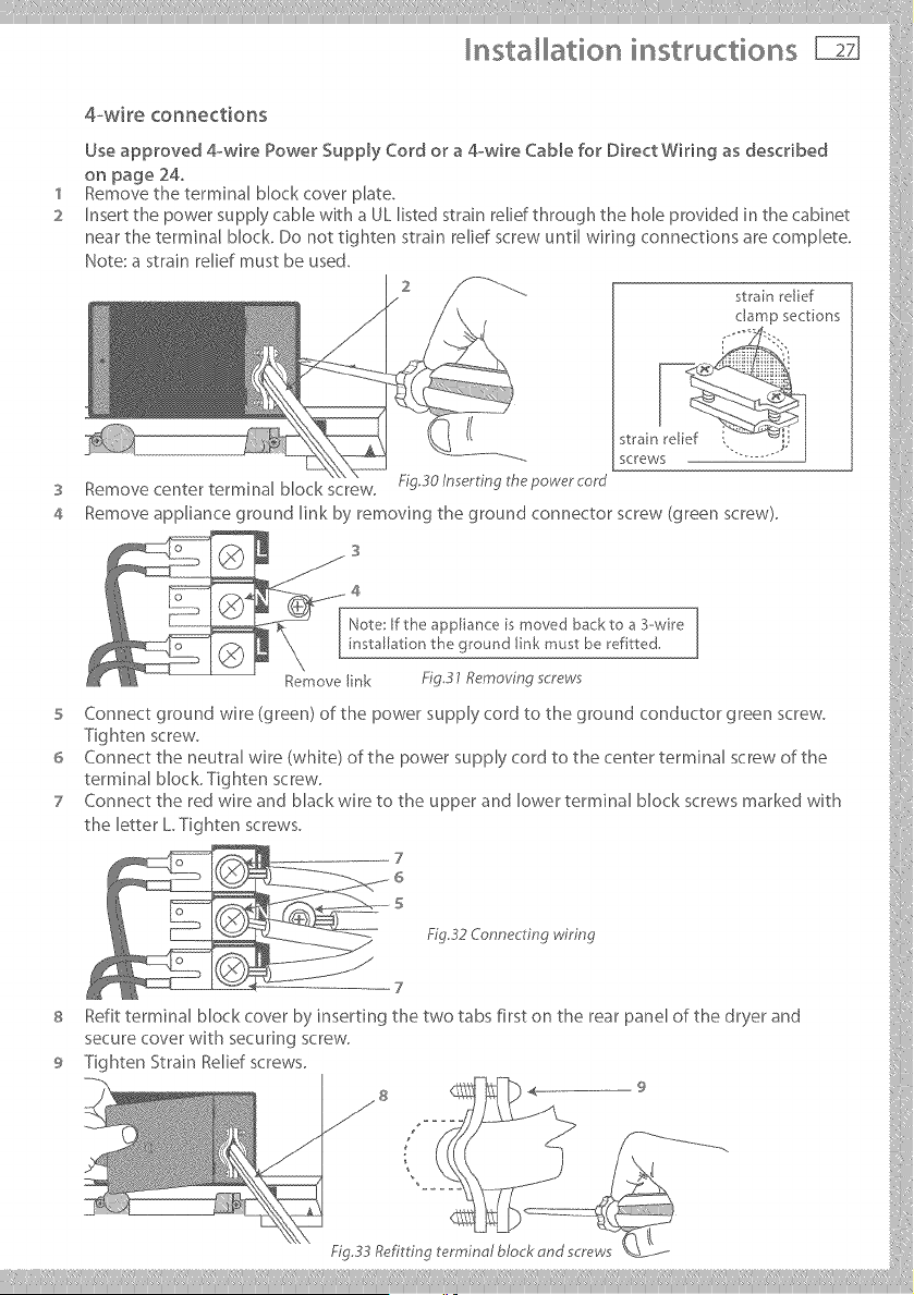
5 Connect ground wire (green) of the power supply cord to the ground conductor green screw.
-Fighten screw.
6 Connect the neutral wire (white) of the power supply cord to the center terminal screw of the
terminal block. Tighten screw,
7 Connect the red wire and Mack wire to the upper and lower terminal block screws marked with }}':
t he letter L Tig htensc rews.
7 ::
6
s
Refittermin_lblockcoverbyinserting_hetwot_bsfirs_on_herearp_nelofthedryer_nd
secure cover with securing screw,
9 Tighten Strain Relief screws.
y ....__..............
nsta ation instructions
Gas requirements (gas models only)
The installation must conform with Local (:odes, or in the absence of Local (::odes, to the
National Fuel Gas (::ode ANSI Z223.1/NFPA 54 or the Canadian Natural Gas and Propane
Installation (::ode, CSA B149.1.
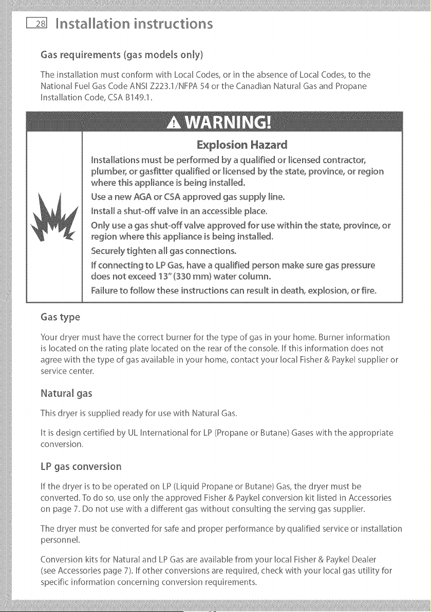
E×D[os[on Hazard
hstaHatbns must be performed by a qualified or _icensed contractor,
pMmber_ or gasfitter qualified or _icensed by the state, province, or region
where this appliance is being instaHedo
Use a new AGA or CSA approved gas supply [ineo
hstaH a shut-off valve in an accessiNe p_aceo
Only use a gas shut-off valve approved for use within the state_ province, or
region where thisappliance isbeing instaHedo
Securely tighten aH gas connections°
F connecting to LP Gas, have a qualified person make sure gas pressure
does not exceed 13" (330 ram) water coMmno
Failure to follow these instructions can result in death, expbsion, or fire°
Gas type
'4our dryer must have the correct burner for the type of gas in your home. Burner information
is located on the rating plate located on the rear of the console. If this information does not
agree with the type of gas available in your home, contact your local Fisher & Paykel supplier or
service center.
Natural gas
This dryer is supplied ready for use with Natural Gas.
It is design certified by UL International for LP (Propane or Butane) Gases with the appropriate
conversion.
LP gas conversion
If the dryer is to be operated on LP (Liquid Propane or Butane) Gas, the dryer must be
converted. TO do so, use only the approved Fisher & Payke[ conversion kit listed in Accessories
on page 7. Do not use with a different gas without consulting the serving gas supplier.
The dryer must be converted for safe and proper performance by qualified service or installation
personnel
Conversion kits for Natural and LP Gas are avaihb[e from your local Fisher & Payke[ Dealer
(see Accessories page 7). If other conversions are required, check with your local gas utility for
specific information concerning conversion requirements.
ii@,!,i@@@@@@@@@@@@@@@@@@@@@@@@ilI_i!llllii,i! iil;_,i!_II_iÀÀ Ililiii:iiiiii_ili lii,i! ll:iiii,i!_iil' iii,i!_li....
Installation instructions
Connecting gas to your dryer (gas models only)
Use compound or thread tape appropriate to the gas type that is to be used (Natural or LP Gas),
on the male threads of all non-flared connections.
Never use an open flame to test for gas leaks.
This dryer will operate satisfactorily up to altitudes of 6500 ft (2000 m) above sea level at the
BTU rating indicated on the model/serial plate. Burner input adjustments may be required if
operating above this elevation.
The dryer must be disconnected from the gas supply system dunng any pressure testing.
Gas ignition
This dryer has an automatic ignition system to ignite the burner. There is no pilot flame burning
in this dryer.
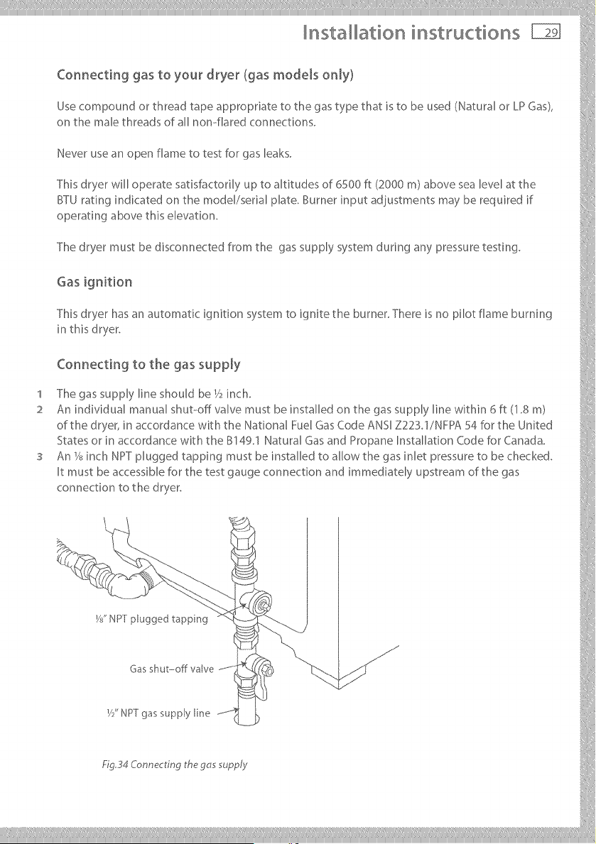
Connecting to the gas supply
'I The gas supply line should be V2inch.
2 An individual manual shut--off valve must be installed on the gas supply line within 6 ft (1.8 m)
of the dryer, in accordance with the National Fuel Gas Code ANSI Z223.1/NFPA 54 for the United
States or in accordance with the B149.1 Natural Gas and Propane Installation Code for Canada.
An_2_inchNPTpluggedtappingmustbeinstaUedtoaUowthegasinletpressuretobechecked.
Itmustbeaccessibleforthetestgaugeconnectionandimmediatel;,upstreamofthegas
connectionto_hedryer.
W' NPTplugg pping
___________
nsta ation instructions
Connecting gas to your dryer (gas models only}
4 A listed connector in compliance with ANSI Z2124/6SA6.10 must be used to connect the dryer
to the gas supply.
5 If flexible tubing is used, an elbow should be installed on the pipe at the back of the dryer for
the flexible tube to be connected to. This will minimize damage to the tube when the dryer is
moved back Use a flexible tubing connection kit that has designed for use on a clothes dryer.
This kit should have the unions necessary to inn to the ends of the tubing. Be sure to follow all
instructions supplied with the kit.
6 Copper tubing should not be used for Natural Gas and if used for LP Gas, it must be LP Gas
compatible.
7 Disconnect and discard old flexible tubing_
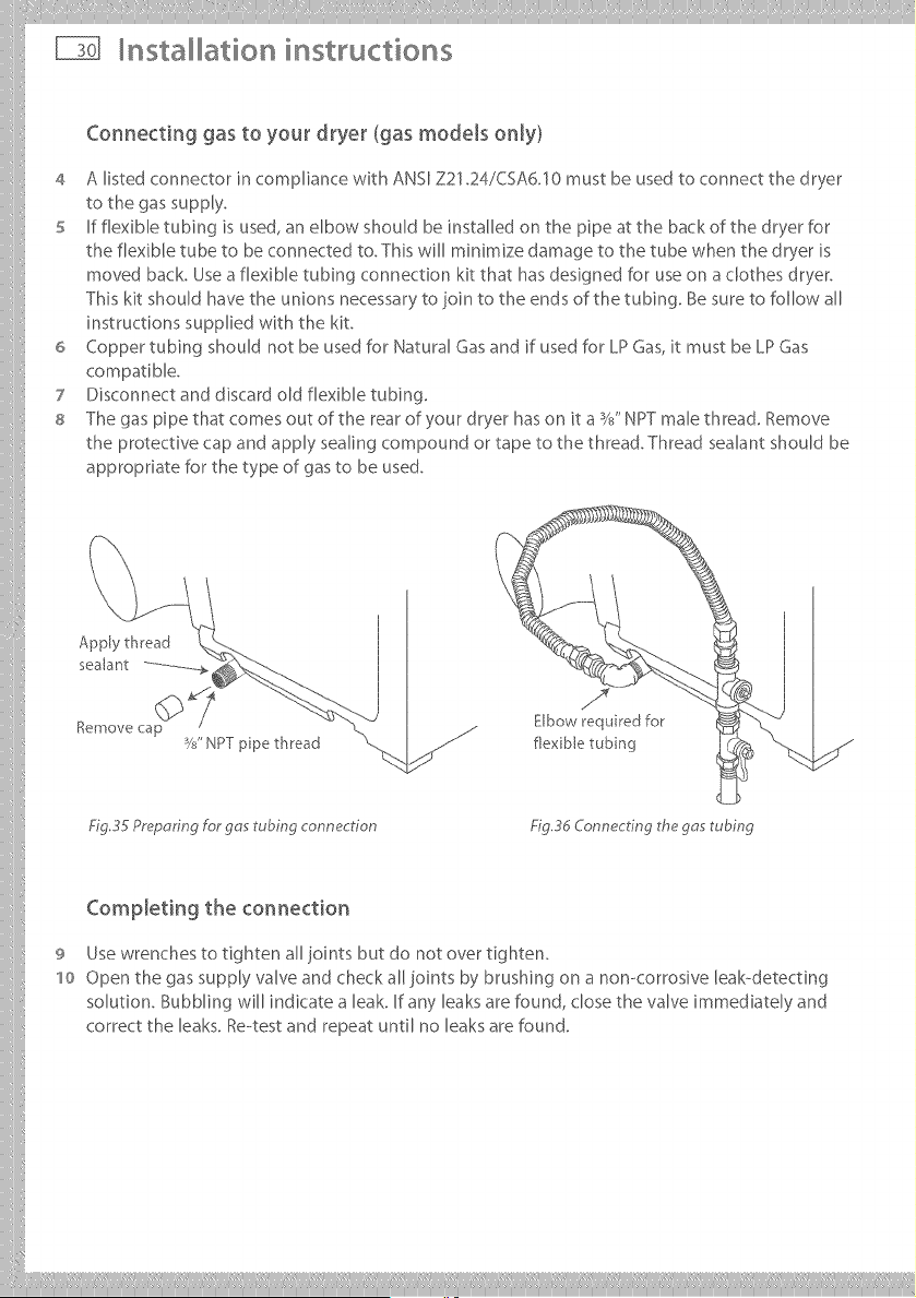
8 The gas pipe that comes out of the rear of your dryer has on it a %" NPT male threaG Remove
the protective cap and apply sealing compound or tape to the thread. Thread sealant should be
appropriate for the type of gas to be used.
Apply thread
sealant ..............
%mow _ cap
W' NPT ppe thread
Elbow required for
flex ble tubing
Fig.35 PrepoHng For gas tubing connection Fig 3d Connecting the gas tubing
CompJeting the connection
9 Use wrenches to tighten all joints but do not over tighten.
'1o Open the gas supply valve and check all joints by brushing on a non-corrosive leak-detecting
solution. Bubbling will indicate a leak. If any leaks are found, close the valve immediately and
correct the leaks. Re--test and repeat until no leaks are found.
iiilI!i!!!!!!! Iliiiliiiill¸IIII IIIiiiiliilli iliiiiilliiillIIIlilililli!lilii_ii!iIlii!IIIi:liii!iiili
Installation instructions
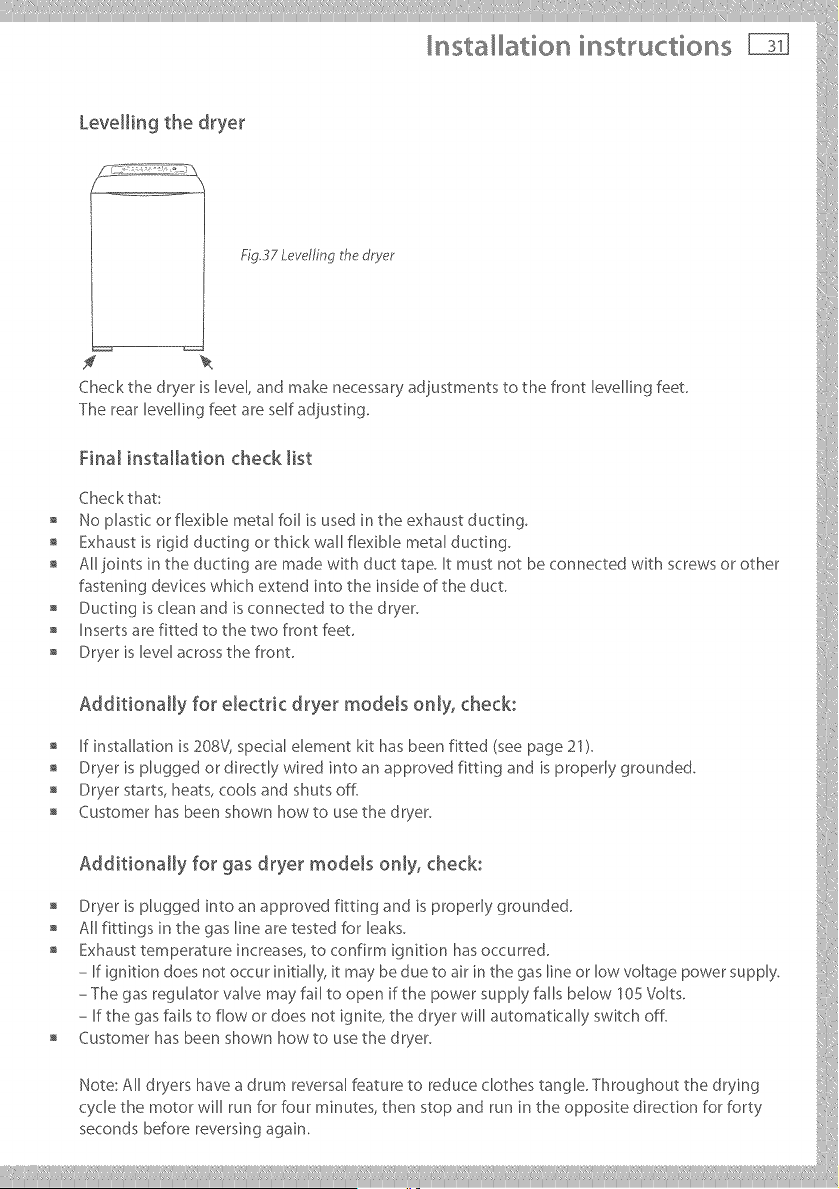
Levellin 9 the @yet
Fig,37 Levelfing the dryer
f
Check the dryer is level, and make necessary adiustments to the front levelling feet.
The rear levelling feet are self adiusting.
Final installation check list
Checkthat:
No plastic or flexible metal foil is used in the exhaust ducting.
Exhaust is rigid ducting or thick wall flexible metal ducting.
All joints in the ducting are made with duct tape. It must not be connected with screws or other
fastening devices whic h extend into the in side of the duct
, Ducting is clean arid is connected to the dryer, i
, Inserts are fitted to the two front feet
o Dryer_s_eve_acrossthefront
Additionally for electdc @yet models only, check:
If installation is 208V, specialelement kit has been fitted (seepage 21).
" Dryer is plugged or directly wired into an approved fitting and is properly grounded, i:,,
, Dryer starts, heats, cools and shuts off.
o Customerhasbeenshownhowtousethedryer
o Additionally for gas @yet models only, check:
Dryer is plugged into an approved fittirlg arid is properly grounded, i
All fittings in the gas line are tested for leaks.
, Exhaust temperature increases, to confirm ignition has occurred.
- If ignition does not occur initially, it may be due to air in the gas line or low voltage power supply.
ThegasregulatorvalvemayfaUtoopen_fthepowersopplyfallsbelow_0SVolts
- If the gas fails to flow or does riot ignite, the dryer will automatically switch off.
, Customer has been shown how to use the dryer.
Note:AUdryershaveadrumreversalfeaturetoreduceclo_hes_angleThroughoutthedrying
cycle the motor will run for four minutes, then stop and run in the opposite direction for forty
secondsbeforereversingagain.
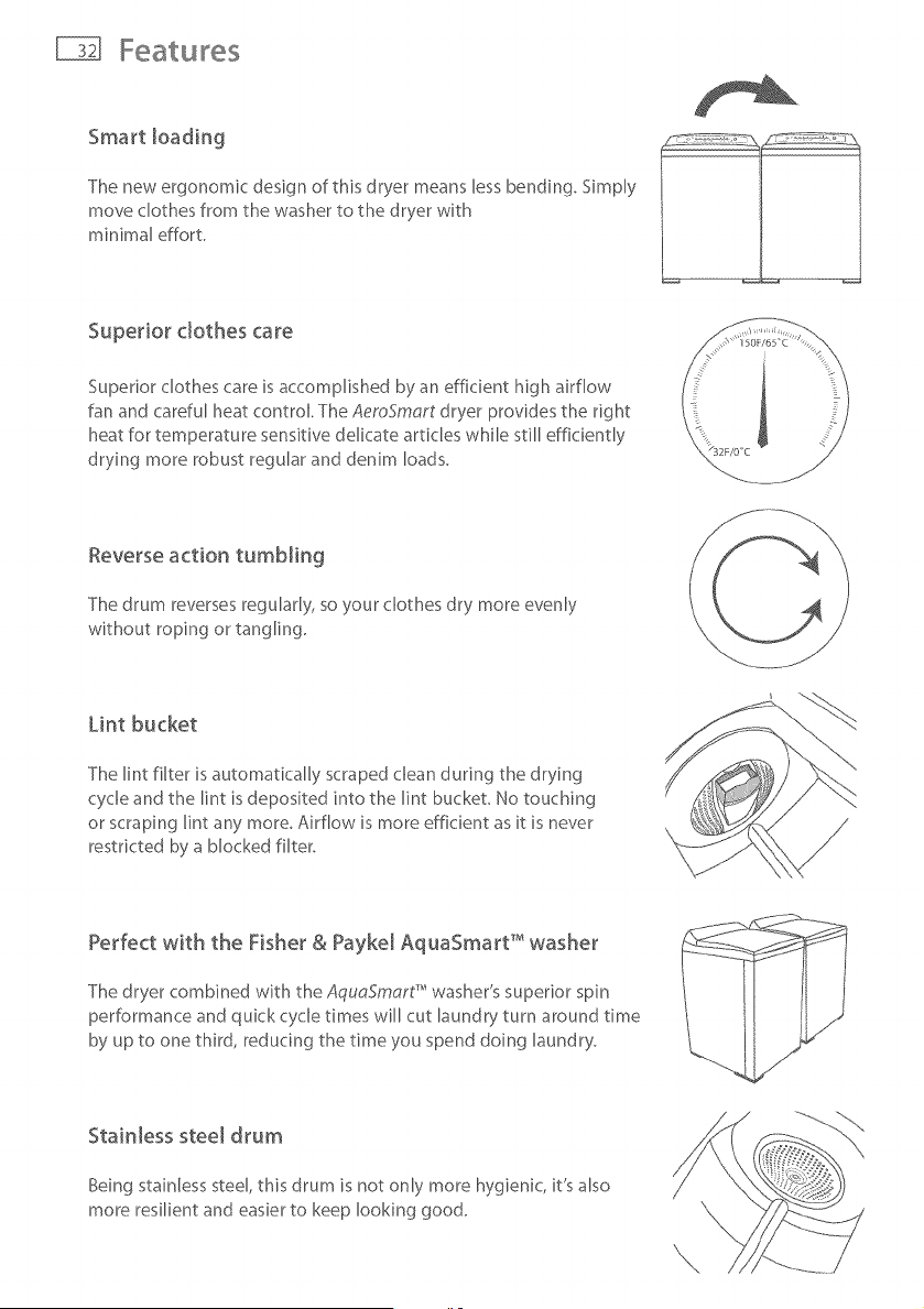
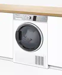
Smart loading
The new ergonomic design of this dryer means less bending. Simply
move clothes from the washer to the dryer with
minimal effort.
Superior clothes care
Superior clothes care is accomplished by an efficient high airflow
fan and careful heat control. The AemSmart dryer provides the right
heat for temperature sensitive delicate articles while still efficiently
drying more robust regular and denim loads.
Reverse action tumbling
The drum reverses regularly, so your clothes dry more evenly
without roping or tangling.
Lint bucket
The lint filter is automatically scraped clean during the drying
cycle and the lint is deposited into the lint bucket, No touching
or scraping lint any more, Airflow is more efficient as it is never
restricted by a blocked filter.
Perfect with the Fisher & Payke[ AquaSmart T'_washer
The dryer combined with the AquaSmart" washer's superior spin
performance and quick cycle times will cut laundry turn around time
by up to one third, reducing the time you spend doing laundry.
Stainless steel drum
Being stainless steel, this drum is not only more hygienic, it's also
more resilient and easier to keep looking good.
The first time you turn your dryer on
Electric Shock Hazard
Read and follow the important safety instructions outlined in this User
Guide before operating this appliance, pages 3 .-6o
Failure to do so can result in death, e_ectric shock, fire or injury to persons°
Close supervision is necessary if this dryer is used by or near children. Do not allow children to
play inside, around or with this dryer or any other appliance.
Control panel lighting
The panel lig hting of your AeroSmart dryer can be adjusted to suit the environment that your
dryer is located in, For a low lighting situation you may need more lighting contrast and for
installations where there is a lot of ambient light, you may need less,
To adjust the control panel lighting
1 Press POWER to activate your AeroSmort dryer,
2 Press and hold the WRINKLE FREE button for 2 seconds until you hear a quick beep, You will
then see a change in the lighting contrast,
s -fb change the setting again simply repeat the process,
Your AeroSmort dryer leaves the factory set for low ambient light conditions,
Getting started quickly
Operating instructions
Sorting
For the best drying results, sort your clothes into similar types
that will take a similar time to dry (refer to Sorting page 36).
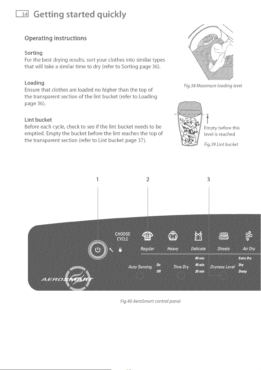
Loading
Ensure that clothes are Roaded no higher than the top of
the transparent section of the lint bucket (refer to Loading
page 36).
FigS8 Maximum Iooding le_cel
Lint bucket
Before each cycle, check to see if the lint bucket needs to be
emptied. Empty the bucket before the lint reaches the top of
the transparent section (refer to Lint bucket page 37).
Fig40 AeroSmort control pone/
Getting started quickly
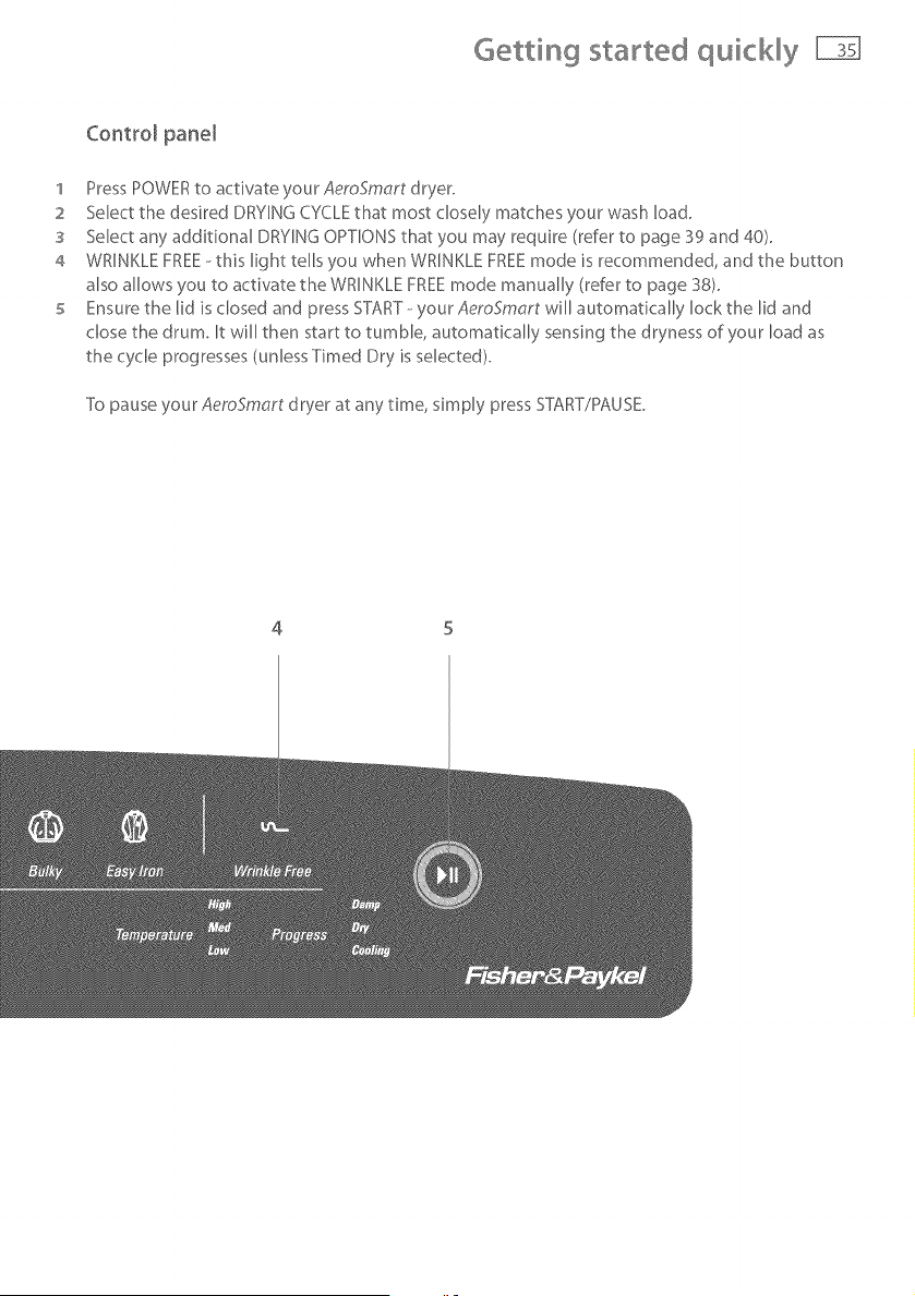
Control pane[
1 Press POWER to activate your AeroSmart dryer.
2 Select the desired DRYING CYCLE that most closely matches your wash load.
3 Select any additional DRYING OPTIONS that you may require (refer to page 39 and 40).
4 WRINKLE FREE--this light tells you when WRINKLE FREE mode is recommended, and the button
also allows you to activate the WRINKLE FREE mode manually (refer to page 38).
5 Ensure the lid is dosed and press START-- your AeroSmart will automatically lock the lid and
chose the drum. It will then start to tumble, automatically sensing the dryness of your load as
the cycle progresses (unless Timed Dry is selected).
To pause your AeroSmart dryer at any time, simply press STT\RT/PAUSE.
4 5
Usingyourdryer
Check the care labels inside the garments to determine whether the garment manufacturer
recommends tumble--drying.
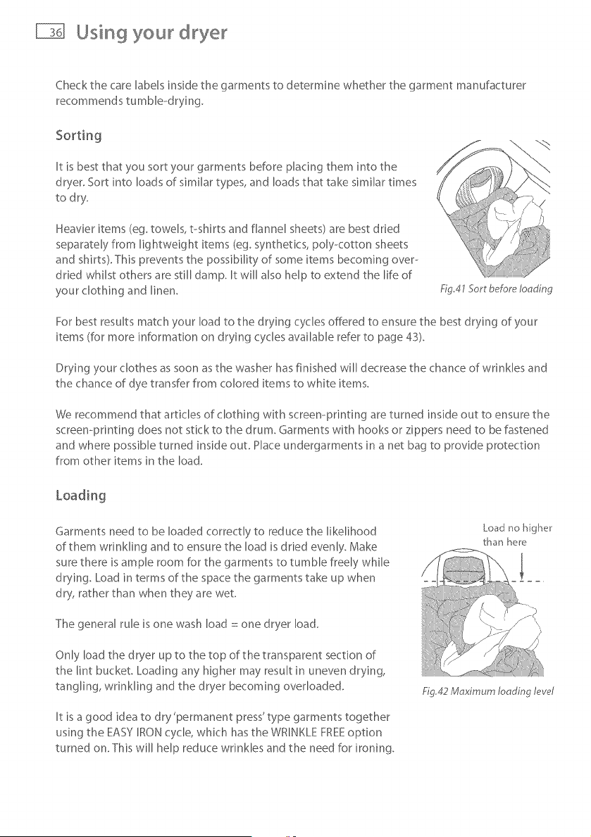
It is best that you sort your garments before placing them into the
dryer. Sort into loads of similar types, and loads that take similar times
to dry.
Heavier items (eg. towels, t-shirts and flannel sheets) are best dried
separately from lightweight items (eg. synthetics, poly<otton sheets
and shirts). This prevents the possibility of some items becoming over--
dried whilst others are still damp. It will also help to extend the life of
your clothing and linen.
Fig.41 Sort before loading
For best results match your load to the drying cycles offered to ensure the best drying of your
items (for more information on drying cycles available refer to page 43).
Drying your clothes as soon as the washer has finished will decrease the chance of wrinkles and
the chance of dye transfer from colored items to white items.
We recommend that articles of clothing with screen-printing are turned inside out to ensure the
screen-printing does not stick to the drum. Garments with hooks or zippers need to be fastened
and where possible turned inside out. Hace undergarments in a net bag to provide protection
from other items in the load.
Garments need to be loaded correctly to reduce the likelihood
of them wrinkling and to ensure the load is dried evenly. Make
sure there is ample room for the garments to tumble freely while
drying. Load in terms of the space the garments take up when
dry, rather than when they are wet.
The general rule is one wash load : one dryer load.
Only load the dryer up to the top of the transparent section of
the lint bucket Loading any higher may result in uneven drying,
tangling, wrinkling and the dryer becoming overloaded.
It is a good idea to dry 'permanent press' type garments together
using the EASY IRON cycle, which has the WRINKLE FREEoption
turned on. This will help reduce wrinkles and the need for ironing.
Load no higher
than here
Ng,42 Maximum loading lew_l
Using your dryer
Lint bucket
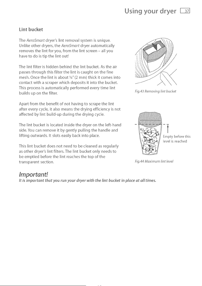
The AeroSmart dryer's lint removal system is unique.
Unlike other dryers, the AeroSmart dryer automatically
removes the lint for you, from the lint screen - all you
have to do is tip the lint out!
The lint filter is hidden behind the lint bucket. As the air
passes through this filter the lint is caught on the fine
mesh. Once the lint is about W' (2 ram) thick it comes into
contact with a scraper which deposits it into the bucket.
This process is automatically performed every time lint
builds up on the filter.
Apart from the benefit of not having to scrape the lint
after every cycle, it also means the drying efficiency is not
affected by lint build-up during the drying cycle.
The lint bucket is located inside the dryer on the left-hand
side, You can remove it by gently pulling the handle and
lifting outwards. It slots easily back into place.
This lint bucket does not need to be cleaned as regularly
as other dryer's lint filters. The lint bucket only needs to
be emptied before the lint reaches the top of the
transparent section.
Fig,43 Removing tint bucket
Empty before this
evel s reached
Fig.44 Mr_ximum lint level
ft is important that you run your dryer with the tint bucket in place at aft times.
Using your dryer
Selecting a cycle
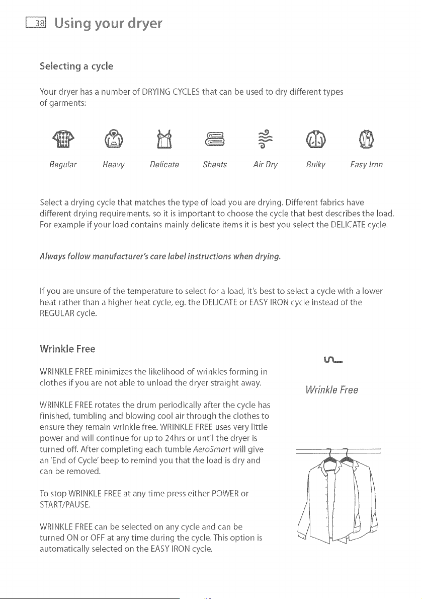
Sour dryer has a number of DRYING CYCLESthat can be used to dry different types
of garments:
Regular Heavy Deficate Sheets Air Dry Bulky Easy/ran
Select a drying cycle that matches the type of load you are drying. Different fabrics have
different drying requirements, so it is important to choose the cycle that best describes the load.
For example if your load contains mainly delicate items it is best you select the DELICATE cycle.
AM, ays foNow manufacturer!s care tabel instructions when drying.
If you are unsure of the temperature to select for a load, it's best to select a cycle with a lower
heat rather than a higher heat cycle, eg. the DELICATE or EASY IRON cycle instead of the
REGULAR cycle.
Wrinkle Free
WRINKLE FREEminimizes the likelihood of wrinkles forming in
clothes if you are not able to unload the dryer straight away.
WRINKLE FREE rotates the drum periodically after the cycle has
finished, tumbling and blowing cool air through the clothes to
ensure they remain wrinkle free. WRINKLE FREE uses very little
power and will continue for up to 24hrs or until the dryer is
turned off. After completing each tumble AeroSmart will give
an 'End of Cycle' beep to remind you that the load is dry and
can be removed.
To stop WRINKLE FREEat any time press either POWER or
STtART/PAUSE.
WRINKLE FREEcan be selected on any cycle and can be
turned ON or OFF at any time during the cycle. This option is
automatically selected on the EASY IRON cycle.
Wrinkle Free
Using your dryer
Selecting the d_ying process
There are two ways in which your dryer is able to dry clothes; AU_:O SENSING or TIME DRS:
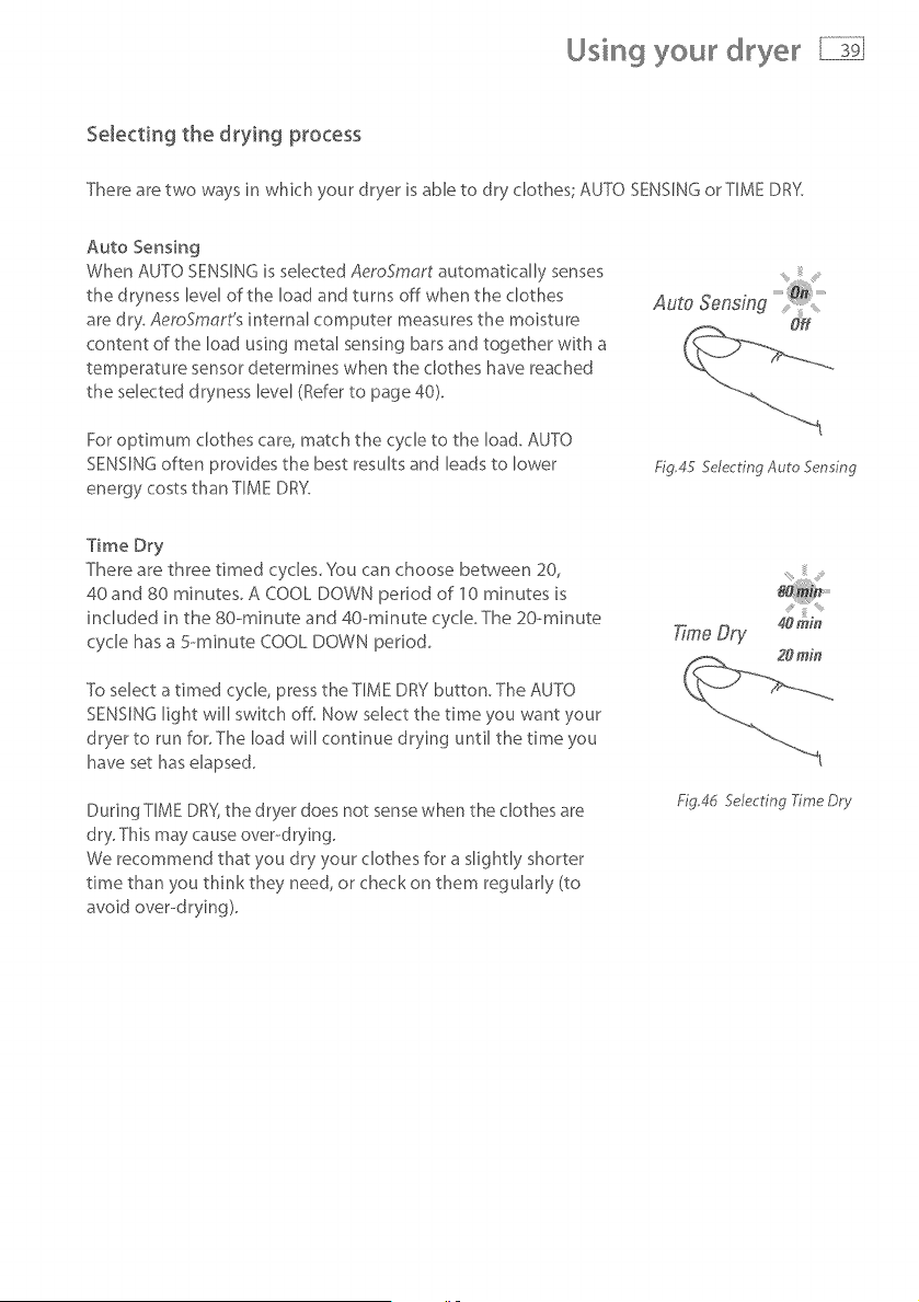
Auto Sensing
When AUTO SENSING is selected AeroSmart automatically senses
the dryness level of the load and turns off when the clothes
are dry. AemSmart's internal computer measures the moisture
content of the load using metal sensing bars and together with a
temperature sensor determines when the clothes have reached
the selected dryness level (Refer to page 40).
For optimum clothes care, match the cycle to the load. AUTO
SENSING often provides the best results and leads to lower
energy costs than TIME DRY.
Fig_45 Selecting Auto Sensing
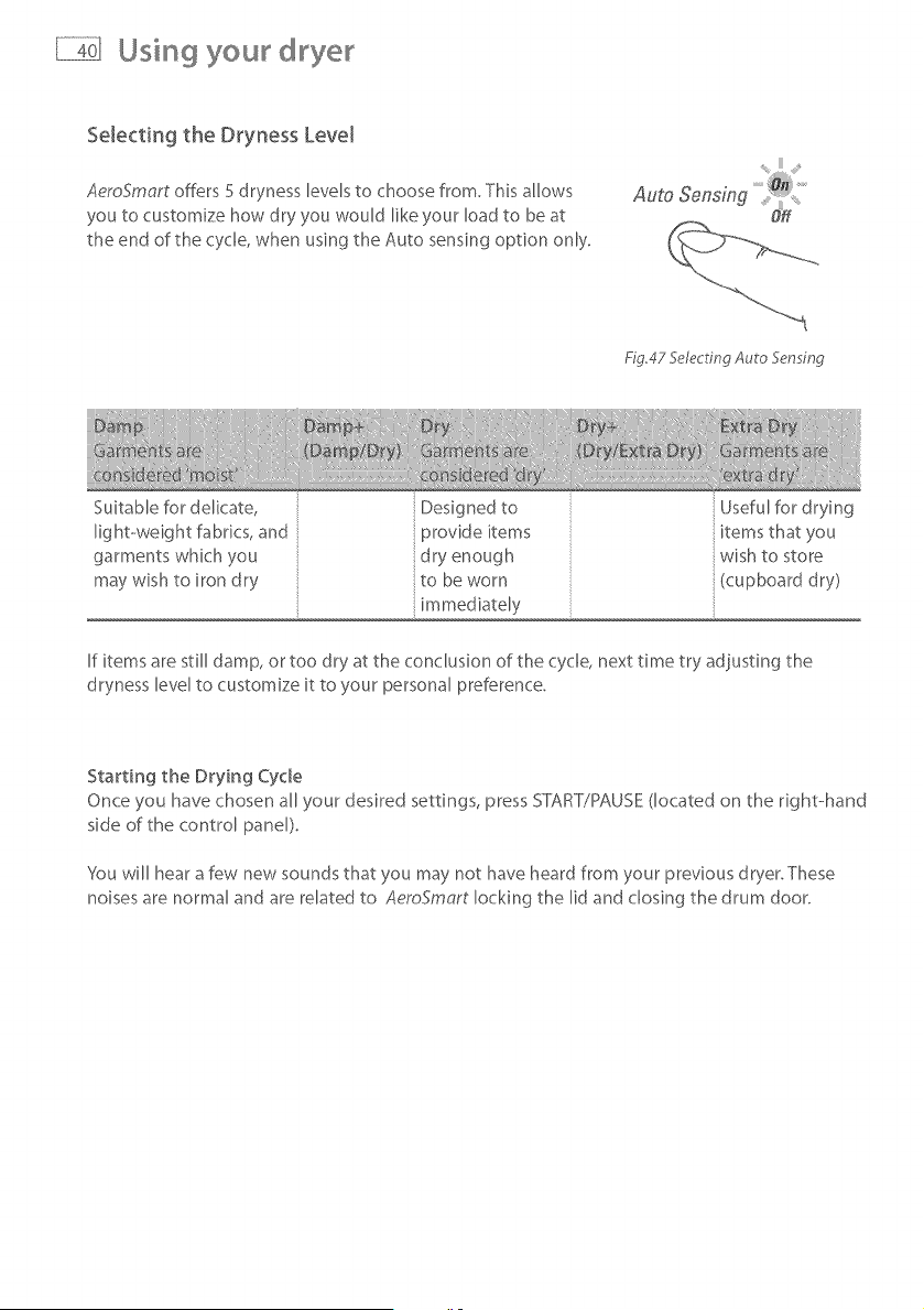
Time Dry
There are three timed cycles You can choose between 20,
40and 80 minutes. A COOL DOWN period of 10 minutes is
included in the 80- minute and 40--minute cycb The 20-minute
cycle has a 5---minute COOL DOWN period
To select a timed cycle, press the TIME DRY button. The AUTO
SENSING light will switch off. Now select the time you want your
dryer to run for. The load will continue drying until the time you
have set has elapsed.
During TIME DR%the dryer does not sense when the clothes are
dry. This may cause over--drying.
We recommend that you dry your clothes for a slightly shorter
time than you think they need, or check on them regularly (to
avoid over--drying).
T;rneDry
Fig,4d Selecting Xme Dr},,
Using your
Selecting the Dryness Level
AeroSmart offers 5 dryness levels to choose from, This allows
you to customize how dry you would like your load to be at
the end of the cycle, when using the Auto sensing option only.
Fig.47 Selecting Auto 5en ing
Suitable for delicate,
light-weight fabrics, and
garments which you
may wish to iron dry
Designedto Usefulfordrying
provide items items that you
dry enough wish to store
to be worn (cupboard dry)
mmed ately
If items are still damp, or too dry at the conclusion of the cycle, next time try adjusting the
dryness level to customize it to your personal preference.
Starting the Drying Cycle
Once you have chosen all your desired settings, press START/PAUSE (located on the right-hand
side of the control panel)
You will hear a few new sounds that you may not have heard from your previous dryer.These
noises are normal and are related to AeroSmart locking the lid and closing the drum door.
Using you d yer
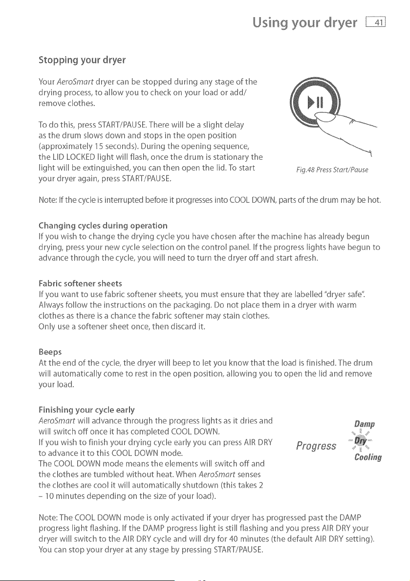
Stopping you_ d_ye_
Your AeroSmart dryer can be stopped dunng any stage of the
drying process, to allow you to check on your load or add/
remove clothes.
To do this, press START/PAUSE There will be a slight delay
as the drum slows down and stops in the open position
(approximately 15 seconds). Dunng the opening sequence,
the LID LOCKED light will flash, once the drum is stationary the
light will be extinguished, you can then open the Iid.To start
your dryer again, press START/PAUSE.
£g.48 Pres Start/Pc, use
Note: If the cycle is interrupted before it progresses into COOL DOWN, parts of the drum may be hot.
Changing cycles during operation
If you wish to change the drying cycle you have chosen after the machine has already begun
drying, press your new cycle selection on the control panel. If the progress lights have begun to
advance through the cycle, you will need to turn the dryer off and start afresh.
Fabric softener sheets
If you want to use fabric softener sheets, you must ensure that they are labelled "dryer safe"
Always follow the instructions on the packaging. Do not place them in a dryer with warm
clothes as there is a chance the fabric softener may stain clothes.
Only use a softener sheet once, then discard it.
Beeps
At the end of the cycle, the dryer will beep to let you know that the load isfinished. The drum
will automatically come to rest in the open position, allowing you to open the lid and remove
your load.
Finishing your cycle early
AeroSmart will advance through the progress lights as it dries and
will switch off once it has completed COOL DOWN.
If you wish to finish your drying cycle early you can press AIR DRY
to advance it to this COOL DOWN mode.
The COOL DOWN mode means the elements will switch off and
the clothes are tumbled without heat. When AeroSmart senses
the clothes are cool it will automatically shutdown (this takes 2
- 10 minutes depending on the size of your load).
Cee/ing
Note: The COOL DOWN mode is only activated if your dryer has progressed past the DAMP
progress light flashing. If the DAMP progress light is still flashing and you press AIR DRY your
dryer will switch to the AIR DRY cycle and will dry for 40 minutes (the default AIR DRY setting).
'_ou can stop your dryer at any stage by pressing START/PAUSE
Changing the drying cycle
Drying cycles explained
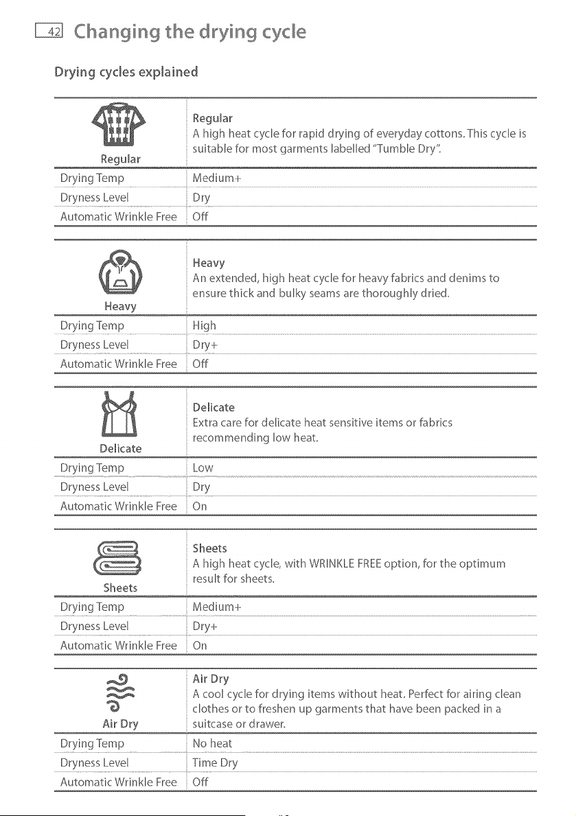
Reg@ar
A high heat cycle for rapid d rying of everyday cottons. This cycle is
suitable for most garments labelled "Tumble Dry"
Regular
Drying Temp Medium+
Dryness Level Dry
Automatic Wrinkle Free Off
Heavy
An extended, high heat cycle for heavy fabrics and denims to
ensure thick and bulky seams are thoroughly dried.
Heavy
Dr.vir_g Temp ..................................H!gh ..................................................................................................................................................................................................................................................................................................................................
Dryness Level Dry-k
Automatic Wrinkle Free Off
DelicateExtra care for delicate heat sensitive items or fabrics
recommending low heat
De[kate
Drying ]%mp Low
Dryness Level Dry
Automatic Wrinkle Free On
Sheets
A high heat cycle, with WRINKLE FREEoption, for the optimum
result for sheets.
Sheets
Drying Temp Medium+
Dryness Level Dry+
Automatk Wrinkle Free On
Air Dry
A cool cycle for drying items without heat Perfect for airing clean
clothes or to freshen up garments that have been packed in a
Air Dry suitcase or drawer.
Drying Temp No heat
Dryness Level Time Dry
Automatic Wrinkle Free Off
Changing the drying cyde
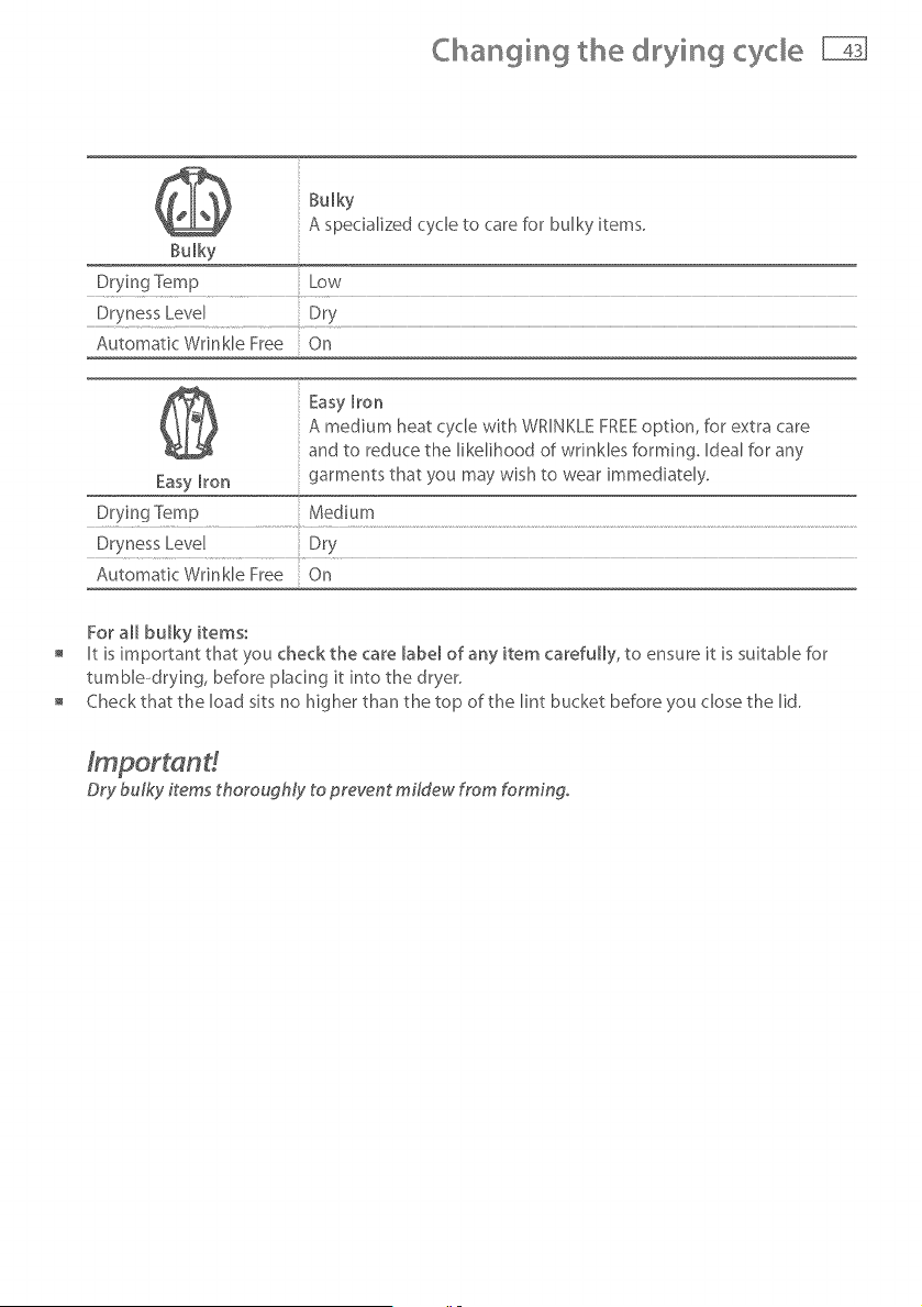
Bulky
A specialized cycle to care for bulky items.
Bulky
Drying Temp Low
Dryness Level Dry
Automatic Wrinkle Free On
Easy Iron
A medium heat cycle with WRINKLE FREEoption, for extra care
and to reduce the likelihood of wrinkles forming. Ideal for any
Easy Iron garments that you may wish to wear immediately.
D!ying Temp ..............................Medium .................................................................................................................................................................................................................................................................................................................
Dryness Level Dry
Automatic Wrinkle Free On
For all bulky items:
It is important that you check the care labe_ of any item carefully, to ensure it is suitable for
tumbb-drying, before placing it into the dryer.
Check that the load sits no higher than the top of the lint bucket before you dose the lid.
Dry bulky items thoroughly to prevent mildew from forming.
© ying specia items
There are some articles that need to be dried in a special way, Before you dry any item that is
not described in AeroSmart's cycles (page 42), refer to the table below. Always remember to
follow the manufacturer's instructions.
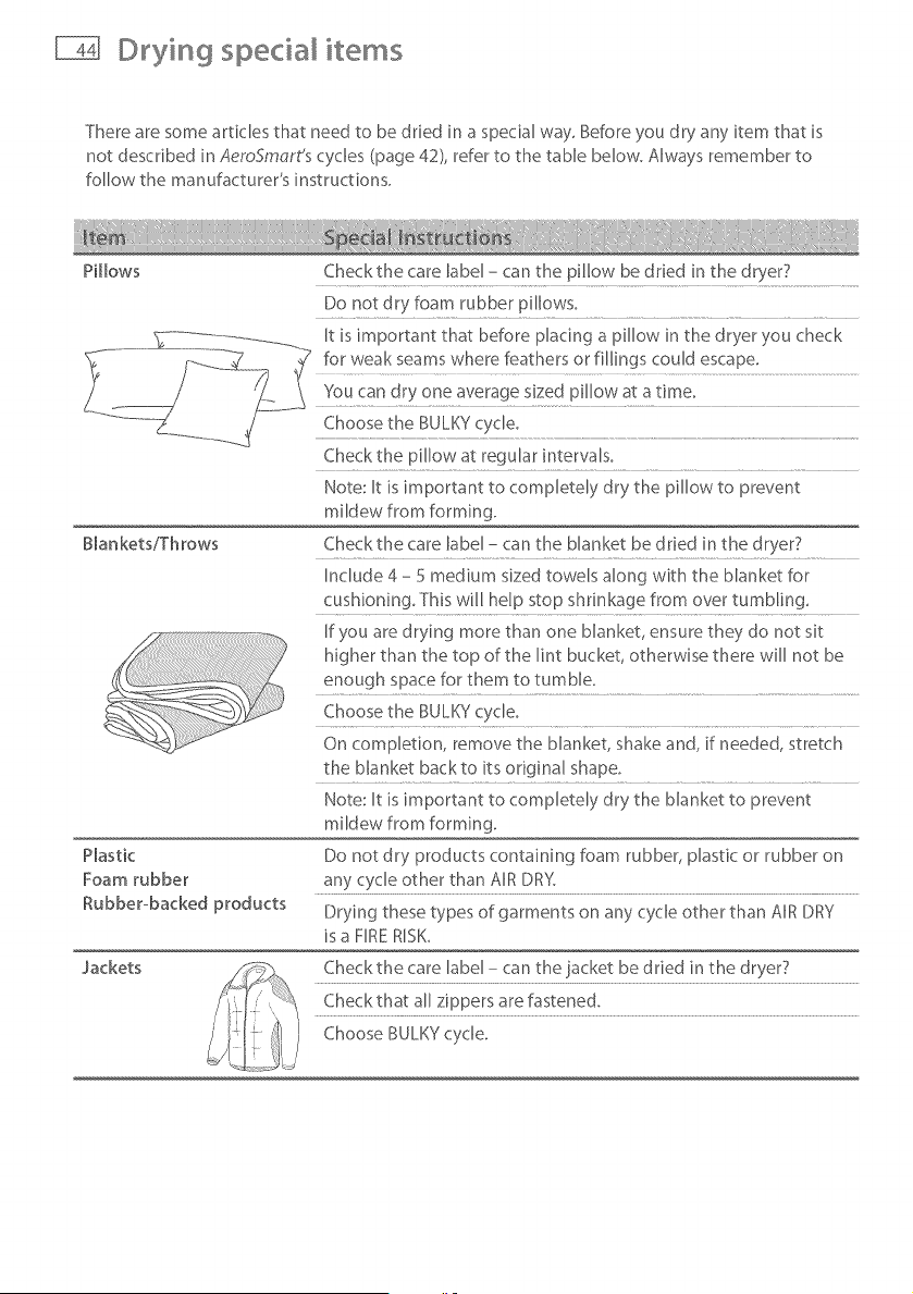
P[[bws
Checkthe care label - can the pillow be dried in the dryer7
Do not dry foam rubber pillows.
Blankets/Throws
Plastic
Foam rubber
Rubber-backed products
Check the pillow at regular intervaB.
Note: It is important to compietdy dry the pillow to prevent
mildew from forming.
Checkthe care label - can the blanket be dried in the dryer?
Include 4 - 5 medium sized towels along with the blanket for
cushioning. This will help stop shrinkage from over tumbling.
If you are drying more than one blanket, ensure they do not sit
higher than the top of the lint bucket, otherwise there will not be
enough space for them to tumble.
Choose the BULKY cycle.
On completion, remove the blanket, shake and, if needed, stretch
the blanket backto its odg[na[ shape.
Note: It is important to comp[etdy dry the blanket to prevent
mildew from forming.
Do not dry products containing foam rubber, plastic or rubber on
any cycle other than AIR DRY.
Drying these types of garments on any cycle other than AIR DRY
is a FIRE R[SK_
Jackets
Check the care label - can the jacket be d tied in the dryer7
Check that all zippers are fastened.
Choose BULKY cycle.
©tying specia items
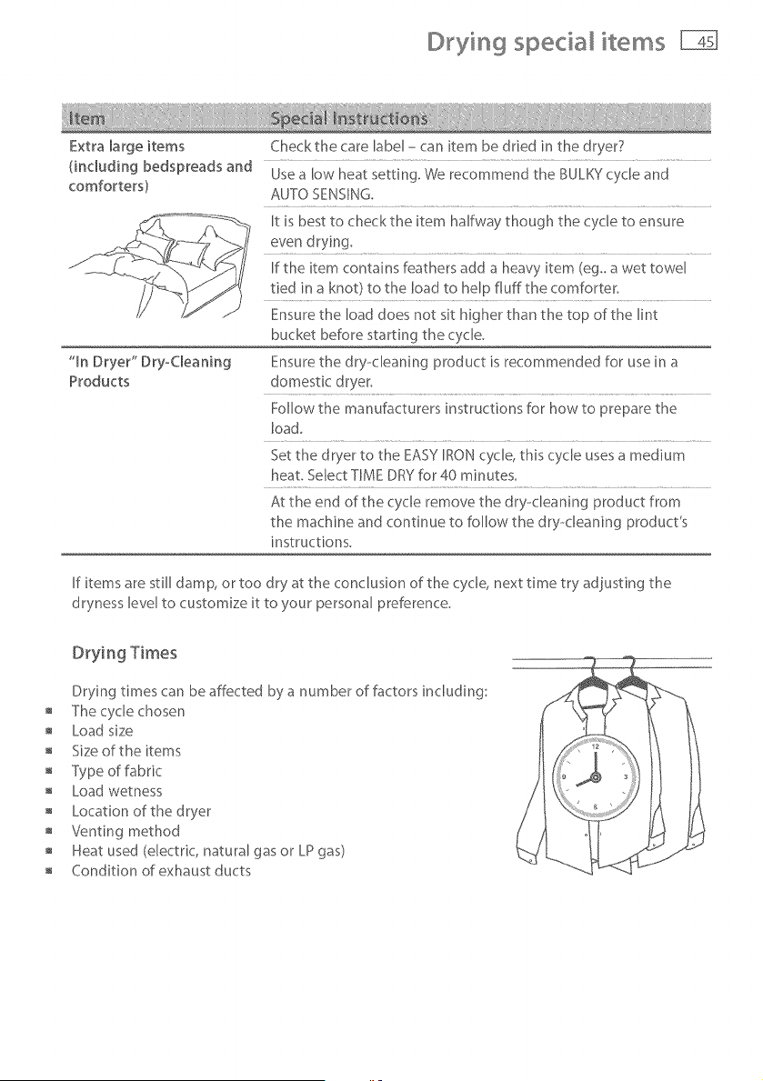
Extra large items
(including bedspreads and
comforters)
"In Dryer" Dry-Cleaning
Products
Checkthe care label - can item be dried in the dryer?
Use a low heat setting. We recommend the BULKY cycle and
AUTO SENSING,
It is best to checkthe item halfway though the cycle to ensure
even dryin%
[f the item contains feathers add a heavy item (eg_ a wet towel
tied in a knot) to the load to help fiufftbe comforter.
Ensure the load does not sit higher than the top of the lint
bucket before starting the cycle.
Ensure the dry-cleaning product is recommended for use in a
domestic dryer.
Follow the manufacturers instructions for how to prepare the
load.
Set the dryer to the EASY IRON cycle, this cy'c[e uses a medium
heat. Select TIME DRY for 40 minutes.
At the end of the cycle remove the dry-cleaning product from
the machine and continue to follow the dry--cleaning product's
instructions.
[f items are still damp, or too dry at the conclusion of the cycle, next time try adjusting the
dryness level to customize it to your personal preference.
Drying Times
Drying times can be affected by a number of factors including:
The cycle chosen
Load size
Size of the items
Type of fabric
Load wetness
Location of the dryer
Venting method
Heat used (electric, natural gas or LP gas)
Condition of exhaust ducts
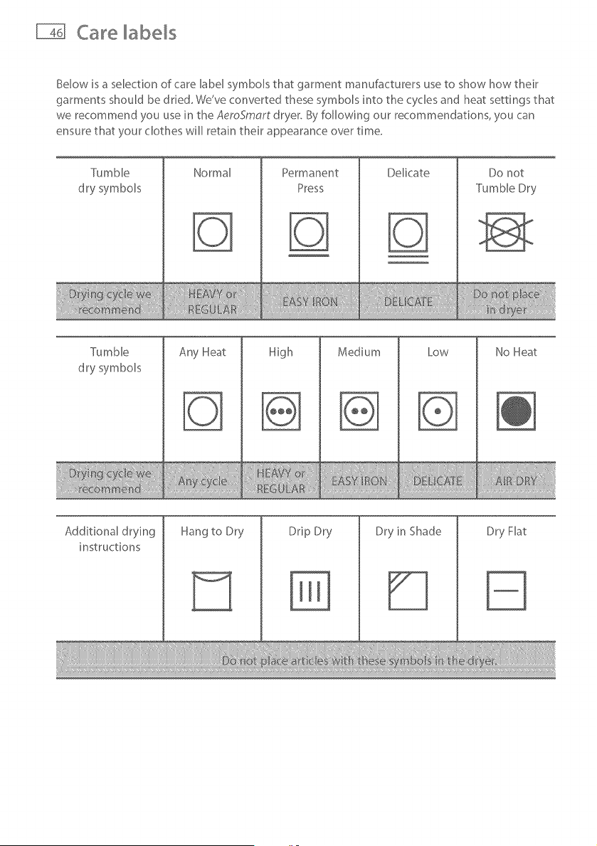
Care labels
Below is a selection of care label symbols that garment manufacturers use to show how their
garments should be dded, We've converted these symbols into the cycles and heat settings that
we recommend you use in the AeroSmart dryer, By following our recommendations, you can
ensure that your clothes will retain their appearance over time,
Tumble
dry symbols
Normal Permanent
Press
Delicate Do not
Tumble Dry
Tumble
dry symbols
Any Heat
High
Medium Low No Heat
Additional drying
instructions
Hang to Dry Drip Dry
%
Dry in Shade Dry Flat
Lid Lock
Your AeroSmort dryer locks its lid at the start of the drying cycle,
providing added safety for you and your family while it is operating.
This lock ensures the lid cannot be opened while the drum is
rotating.
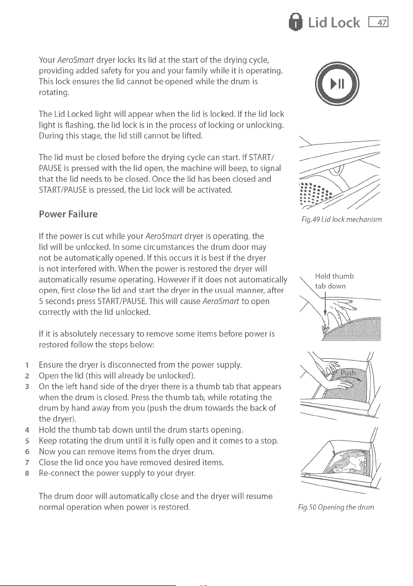
The Lid Locked light will appear when the lid is locked. If the lid lock
light is flashing, the lid lock is in the process of locking or unlocking.
During this stage, the lid still cannot be lifted.
The lid must be closed before the drying cycle can start. If START/
PAUSE is pressed with the lid open, the machine will beep, to signal
that tile lid needs to be closed. Once tile lid has been dosed and
SYT\RT/PAUSEis pressed, the Lid lock will be activated.
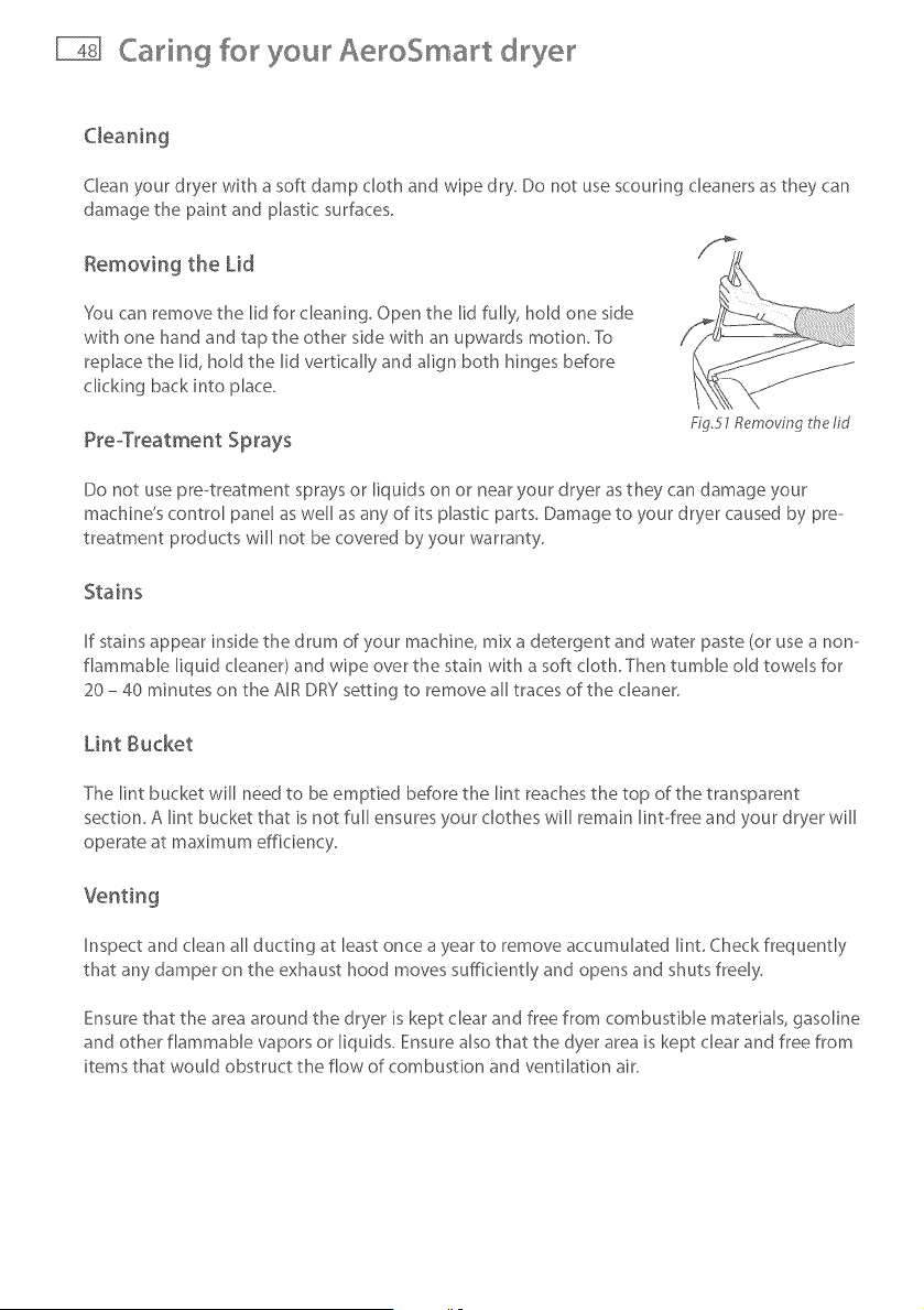
Power Failure
If the power is cut while your AeroSmart dryer is operating, the
lid will be unlocked. In some circumstances the drum door may
not be automatically opened. If this occurs it is best if the dryer
is not interfered with. When the power is restored the dryer will
automatically resume operating. However if it does not automatically
open, first close the lid and start the dryer in the usual manner, after
5 seconds press START/PAUSE.This will cause AeroSmort to open
correctly with the lid unlocked.
If it is absolutely necessary to remove some items before power is
restored follow the steps below:
1 Ensure the dryer is disconnected from the power supply.
2 Open tile lid (this will already be unlocked).
s On the left hand side of the dryer there is a thumb tab that appears
when the drum is closed. Press the thumb tab, while rotating the
drum by hand away from you (push the drum towards the back of
the dryer).
4 Hold the thumb tab down until the drum starts opening.
5 Keep rotating the drum until it is fully open and it comes to a stop.
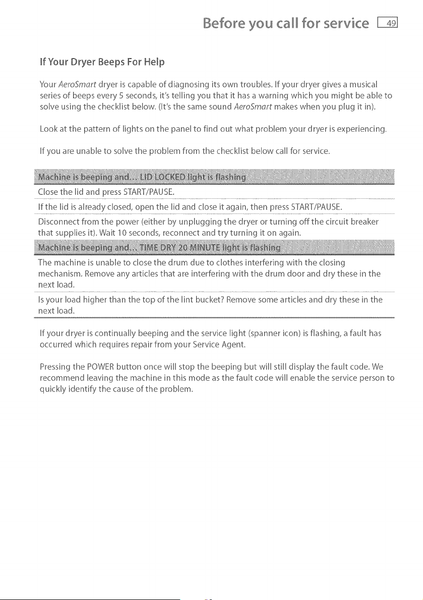
6 Now you can remove items from the dryer drum.
7 Close the lid once you have removed desired items.
s Re-connect the power supply to your dryer.
£g.49 Lid lock mechanism
The drum door will automatically close and the dryer will resume
normal operation when power is restored. £g5o Opening ttm drum
Caring for your AeroSmart dryer
Clean your dryer with a soft damp cloth and wipe dry. Do not use scouring cleaners as they can
damage the paint and plastic surfaces.
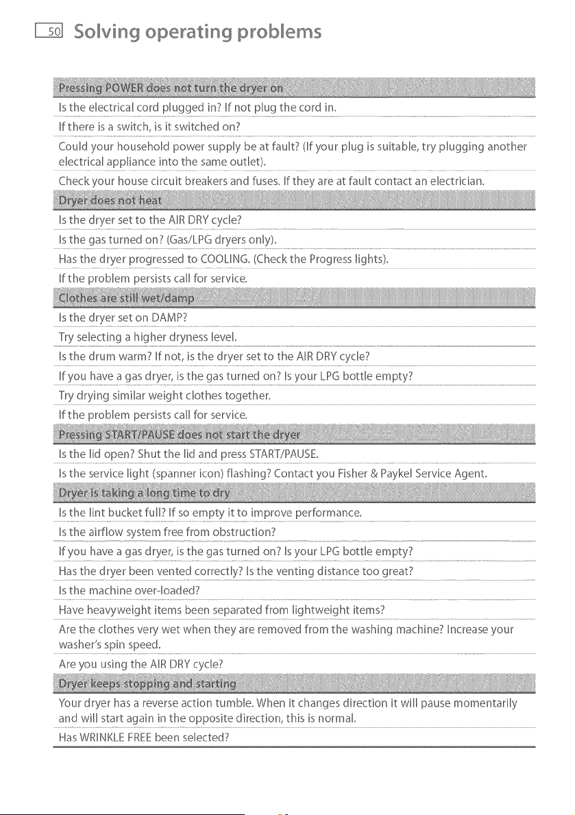
Removing the Lid
You can remove the lid for cleaning. Open the lid fully, hold one side
with one hand and tap the other side with an upwards motion. To
replace the lid, hold the lid vertically and align both hinges before
clicking back into place.
PreoTreatment Sprays
Fig.51 Removing the lid
Do not use pre--treatment sprays or liquids on or near your dryer as they can damage your
machine's control panel as well as any of its plastic parts. Damage to your dryer caused by pre--
treatment products will not be covered by your warranty.
Stains
If stains appear inside the drum of your machine, mix a detergent and water paste (or use a non--
flammable liquid cleaner) and wipe over the stain with a soft cloth. Then tumble old towels for
20 - 40 minutes on the AIR DRY setting to remove all traces of the cleaner.
Lint Bucket
The lint bucket will need to be emptied before the lint reaches the top of the transparent
section. A lint bucket that is not full ensures your clothes will remain lint-ofree and your dryer will
operate at maximum efficiency.
Inspect and clean all ducting at least once a year to remove accumulated lint. Check frequently
that any damper on the exhaust hood moves sufficiently and opens and shuts freely.
Ensure that the area around the dryer is kept clear and free from combustible materials, gasoline
and other flammable vapors or liquids. Ensure also that the dyer area is kept clear and free from
items that would obstruct the flow of combustion and ventilation air.
Before you for servke
If Your Dryer Beeps For Help
SourAeroSmart dryer is capable of diagnosing its own troubles. If your dryer gives a musical
series of beeps every 5 seconds, it's telling you that it has a warning whkh you might be able to
solve using the checklist below. (It's the same sound AeroSmart makes when you plug it in).
Look at the pattern of lights on the panel to find out what problem your dryer is experiencing.
If you are unable to solve the problem from the checklist below call for servke.
Close the lid and press START/PAUSE_
If the lid is already closed, open the lid and close it again, then press ST}_F[TYPAUSE_
Disconnect from the power (either by unplugging the dryer or turning offthe circuit breaker
that supplies i¢ Wait 10seconds, reconnect and try turning it on again_
The machine is unable to dose the drum due to clothes interfering with the closing
mechanism, Remove any articles that are interfering with the drum door and dry these in the
next load,
Isyour load higher than the top of the lint bucket7 Remove some articles and dry these in the
next load.
If your dryer is continually beeping and the service light (spanner icon) is flashing, a fault has
occurred which requires repair from your Service Agent.
Pressing the POWER button once will stop the beeping but will still display the fault code. We
recommend leaving the machine in this mode as the fault code will enable the service person to
quickly identify the cause of the problem.
So ving operati sg prob em, s
Is the electrical cord plugged in7 If not plug the cord in,
If there is a switch, is it switched on7
Could your household power supply be at fault7 (If your plug is suitable, try plugging another
dectrical appliance into the same outlet),
Checkyour house circuit breakers and fuses, If they are at fault contact an electrician,
Is the dryer set to the AIR DRY cycle7
Is the gas turned on7 (Gas/LPG dryers only),
Has the dryer progressed to COOUNG_ (Check the Progress lights}_
If the problem persists call for service.
Is the dryer set on DAMP?
Try selecting a higher dryness level.
Is the drum warm7 If not is the dryer set to the AIR DRY cycle7
If you have a gas dryer, is the gas turned on7 Is your LPG bottle empty7
Try drying similar weight clothes together_
If the problem persists call for service,
Is the lid open? Shut the lid and press START7PAUSE,
Is the service light (spanner icon) flashing7 Contact you Fisher & Paykd Service Agent,
Is the lint bucket full7 If so empty it to improve performance_
Is the airflow system free from obstruction7
If you have a gas dryer, is the gas turned on7 Is your LPG bottle empty7
Has the dryer been vented correctly7 Isthe venting distance too great7
Is the machine overqoaded7
Have heavyweight items been separated from lightweight items7
Are the clothes very wet when they are removed from the washing machine? Increase your
washer's spin speed,
Are you using the AIR DRY cycle7
'_esur dryer has a reverse action tumble. When it changes direction it will pause momentarily
and will start again in the opposite direction this is normal
Has WRINKLE FREE been selected7
So ving drying proMems
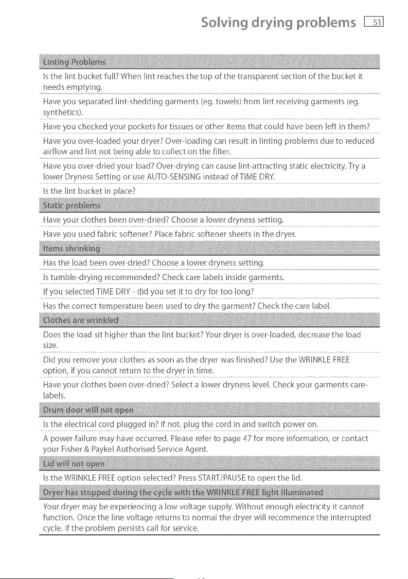
Is the lint bucket full? When lint reaches the top of the transparent section of the bucket it
needs emptying.
Have you separated lint-shedding garments (eg. towers) from Rint receiving garments (eg.
Have you checked your pockets for tissues or other items that could have been left in them?
Have you over-loaded your dryer? Over--loading can result in linting problems due to reduced
airflow and lint not being able to collect on the filter.
Have you over--dried your load? Over-drying can cause lint-attracting static electricity. Try a
lower Dryness Setting or use AUTO-SENSING instead of TIME DRY.
Is the lint bucket in place?
Have your clothes been overdried7 Choose a lower dryness setting
Have you used fabric softener? Place fabric softener sheets in the dryer.
Has the load been over-dried? Choose a lower dryness setting,
Is tumble-drying recommended7 Check care labels inside garments_
If you selected TIME DRY --did you set it to dry for too long?
Has the correct temperature been used to dry the garment? Checkthe care label.
Does the load sit higher than the lint bucket? }four dryer is overdoaded, decrease the load
size.
Did you remove your clothes as soon as the dryer was finished? Use the WRINKLE FREE
option, if you cannot return to the dryer in time_
Have your clothes been over--dried7 Select a lower dryness level. Check your garments care--
labels_
Is the electrical cord plugged in? If not, plug the cord in and switch power on.
A power failure may have occurred. Please refer to page 47 for more information, or contact
your Fisher & Paykel Authonsed Service Agent,
Is the WRINKLE FREEoption selected? Press START/PAUSE to open the lid.
Your dryer may be experiencing a low voltage supply. Without enough electricity it cannot
function, Once the line voltage returns to normal the dryer will recommence the interrupted
cycle, If the problem persists call for service,
Limited warranty
When you purchase any new Fisher & Paykel whiteware product for personal or consumer
use you automatically receive a one year limited warranty covering parts and labor for
servicing within the 48 mainland United States, Hawaii, Washington DC and Canada. In
Alaska the limited warranty is the same except that you must pay to ship the product to
the service shop or the service technician's travel to your home. Products for use in Canada
must be purchased through the Canadian distribution channel to ensure regulatory
compliance.
If the product is installed in a motor vehicle, boat or similar mobile facility, you receive the
same one year limited warranty, but you must bring the vehicle, boat or mobile facility
containing the product to the service shop at your expense or pay the service technician's
travel to the location of the product.
Fisher & Payke[ undertakes to:
Repair without cost to the owner either for material or labor any part of the product, the
serial number of which appears on the product, which is found to be defective. In Alaska,
you must pay to ship the product to the service shop or for the service technician's travel
to your home. If the product is installed in a motor vehicle, boat or similar mobile facility,
you must bring it to the service shop at your expense or pay for the service technician's
travel to the location of the product. If we are unable to repair a defective part of the
product after a reasonable number of attempts, at our option we may replace the part or
the product, or we may provide you a full refund of the purchase price of the product (not
including installation or other charges).
This warranty extends to the original purchaser and any succeeding owner of the product
for products purchased for ordinary single-family home use.
All service under this limited warranty shall be provided by Fisher& Paykelor its
Authorized ServiceAgent during normal business hours,
How long does this limited warranty last?
Our liability under this limited warranty expires ONE YEAR from the date of purchase of
the product by the first consumer.
Our liability under any implied warranties, including the implied warranty of
merchantability (an unwritten warranty that the product is fit for ordinary use) also expires
ONE YEAR (or such longer period as required by appIicaHe law) from the date of purchase
of the product by the first consumer. Some States do not allow limitations on how long an
implied warranty lasts, so this limit on implied warranties may not apply to you.
Limited warranty
c
D
This warranty does not cover:
Service calls that are not related to any defect in the product. The cost of a service call will be
charged if the problem is not found to be a defect of the product. For example:
1. Correct faulty installation of the product.
2. Instruct you how to use the product.
3. Replace house fuses, reset circuit breakers, correct house wiring or plumbing, or replace
light bulbs.
4. Correct fault(s) caused by the user.
5. Change the sebup of the product.
6. Unauthorized modifications of the product.
7. Noise or vibration that is considered normal, for example, drain/fan sounds, refrigeration
noises or user warning beeps.
8. Correcting damage caused by pests, for example, rats, cockroaches etc.
Defects caused by factors other than:
1. Normal domestic use or
2. Use in accordance with the product's user guide.
Defects to the product caused by accident, neglect, misuse, fire, flood or Act of God.
The cost of repairs carried out by non--authorized repairers or the cost of correcting such
unauthorized repairs.
Travel fees and associated charges incurred when the product is installed in a location with
limited or restricted access. (eg. airplane flights, ferry charges, isolated geographic areas).
Normal recommended maintenance as set forth in the product's user guide.
If you have an installation problem contact your dealer or installer. You are responsible for
providing adequate electrical, exhausting and other connection facilities.
We are not responsible for consequential or incidental damages (the cost of repairing or
replacing other property damaged if the product is defective or any of your expenses caused if
the product is defective). Some States do not allow the exclusion or limitation of incidental or
consequential damages, so the above limitation or exclusion may not apply to you.
Limited warranty
How to get service
Please read your User Guide. If you then have any questions about operating the product,
need the name of your local Fisher & Paykel Authorized Service Agent, or believe the product is
defective and wish service under this limited warranty, please contact your dealer or call us at:
USA and Canada
TOLL FREE l°888°9,FNRUSA (1,888,936,7872)
or use the link at: www, fisherpayket,comitocatoriserviceri
You may be required to provide reasonable proof of the date of purchase of the product before
the product will be serviced under this limited warranty.
Commercial use
If you are using the product in a commercial setting (any use other than a single family dwelling),
we agree to repair or replace, without cost to you for parts only, any defective parts, the serial
number of which appears on the product. Our liability for these repairs expires ONE YEAR from
the date of original purchase.
At our option we may replace the part or the product, or we may provide you a full refund of
the purchase price of the product (not including installation or other charges). All service under
this limited warranty shall be provided by Fisher & Paykd or its Authorized Service Agent during
normal business hours.
No other warranties
This limited warranty is the complete and exclusive agreement between you and Fisher & Paykd
regarding any defect in the product. None of our employees (or our Authorized Service Agents)
are authorized to make any addition or modification to this limited warranty.
Warrantor: Fisher & Paykd Appliances, Inc.
If you need further help concerning this limited warranty, please call us at above number, or
write to:
Fisher & Paykel Appliances, Inc.
5900 Skylab Road
Huntington Beach
CA 92647
This limited warranty gives you specific legal rights, and you may also have other rights which
vary from state to state.