Loading ...
Loading ...
Loading ...
28
Drain Pump Removal Instructions:
1. Unplug the ice machine from the electrical supply and
remove the rear access cover from the ice machine.
(See page 26 for instructions).
2. Remove the front panel and the toe grille from the front
of the ice machine. See Figures 43 and 43a.
3. Remove the front and rear drain pump brackets. See
Figures 44, 44a and 45.
4. Unscrew the 3 hose clamps and remove the 3 hoses
from the front of the drain pump. (See Figure 42).
5. Unscrew the leveling leg in the back corner until the
end of the threaded portion is ush with the threaded
nut insert in the base. (see Figure 42).
To Restart the Ice Machine
1. Reconnect or turn on the water supply line.
2. Reconnect drain tubing if removed.
3. Plug in the power cord to a wall outlet and turn the ice
machine on, (refer to page 15 for turning the ice ma-
chine on and off).
4. Check the water inlet, drain lines, and ttings for any
water leaks.
5. Check drain pump (if equipped) operation by pouring
approximately two (2) quarts of water into the ice stor-
age bin. The drain pump should activate and discharge
water (refer to Drain Pump on page 7). Check for
water leaks at all hose connections.
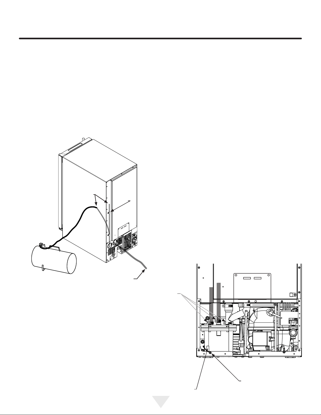
14. Remove the top clamp from the vent tube, for easier
access for the air hose.
15. Apply air pressure (approximately 10 psi) to the end of
the vent tube which will purge the remainder of the
water from the drain pump and the drain line. (See
Figure 41).
16. Reinstall the vent tube and clamp to the back of the ice
machine and remove the winterization plug from the ice
bin and save it for future use.
Figure 41
Vent
tube
Remove
clamp
screw
Drain
line
PREPARING THE ICE MACHINE FOR STORAGE
Unscrew the
leveling leg so
the end of the
threads is ush
with the top of
the nut insert.
Remove
these 3 hose
clamps, then
remove the
3 tubes from
the drain
pump
Drain pump ground
wire connection
Figure 42
Loading ...
Loading ...
Loading ...