Loading ...
Loading ...
Loading ...
22
OVERLAY DOOR PANEL INSTALLATION
Material Type #10 Wood Screw
Hardwood
1
⁄8" (3.2 mm) Diameter Pilot Hole
Softwood
7
⁄64 (2.8 mm) Diameter Pilot Hole
Table B
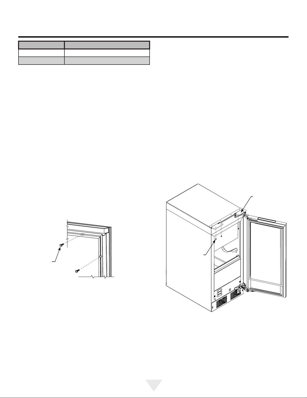
Figure 35
#10 x
1
⁄2"
screw
Step 4: Assemble the panel to the door
The preferred method of attaching the panel to the door
is to clamp the panel to the door so it cannot move while
drilling the screw pilot holes. Use bar clamps or "C" clamps
with pads on the clamping surfaces that will not mar the
panel or the door. The custom overlay panel should be
ush with the top of the door and centered along the width
of the door. See Figure 30a. Drill holes through the gasket
extrusion using the 10 holes as pilot holes. Use the drill
size from the chart in Table "B", being careful not to drill
through the front surface of the panel. If the overlay panel is
thinner than
5
⁄8" (16 mm) thick shorter screws will have to be
obtained. Fasten the panel to the door with the 10 screws
provided in the literature pack. (See Figure 35). Remove
the clamps and replace the gasket in the gasket extrusion
channels of the door. Some force may be required to seat
the gasket into the channels. Be sure the gasket corners
are seated properly.
Step 6: Secure the cabinet
Use the #8 x
3
⁄4" black screws from the literature pack to
secure the counter top to the cabinet top through the holes
in the cabinet "Z" bracket.
Step 5: Install the door
Carefully open the top and bottom hinges on the door being
careful as there are many pinch points. Place the hinges
over the 4 screws in the cabinet, 2 at the top and 2 at the
bottom and slide the door into position. Tighten the 4 hinge
screws with a phillips screwdriver. (See Figures 28 and
28a). Place wire harness from the grille and mount to the
bottom of the door with the screw and "P" clamp removed
in step 1. (See Figure 28b). Reconnect the wire harness,
(See Figure 29).
Figure 36
Cabinet
"Z" bracket
#8 x
3
⁄4" black
screws
(3 places)
Loading ...
Loading ...
Loading ...