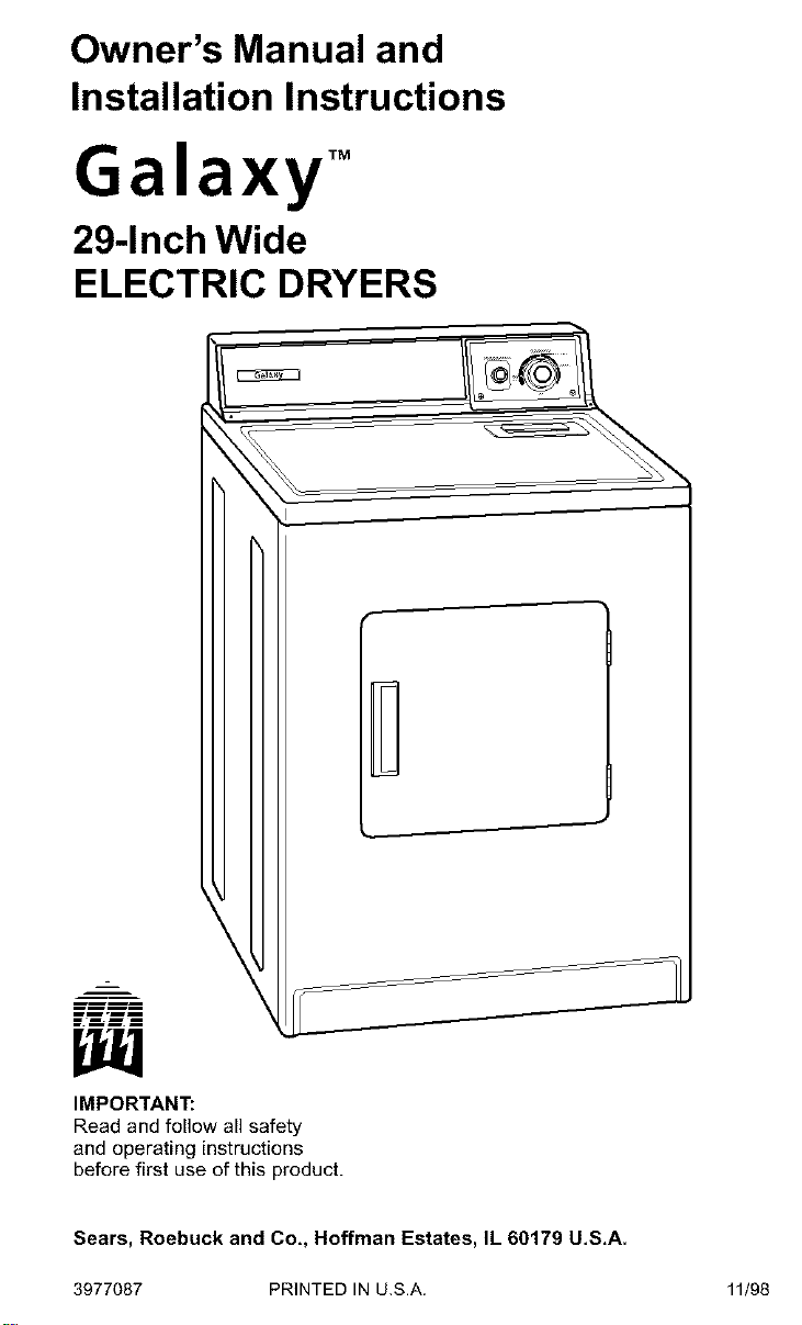
Owner's Manual and
Installation Instructions
Galaxy TM
29-Inch Wide
ELECTRIC DRYERS
r
mm-ml
_mmm
IMPORTANT:
Read and follow all safety
and operating instructions
before first use of this product.
Sears, Roebuck and Co,, Hoffman Estates, IL 60179 U,S,A.
3977087 PRINTED IN U.S.A.
11/98
BEFORE USING YOUR NEW DRYER
GALAXY TM ELECTRIC DRYER WARRANTY 3
DRYER SAFETY 4
INSTALLATION INSTRUCTIONS 5
OPERATING YOUR DRYER 28
CARING FOR YOUR DRYER 30
TROUBLESHOOTING 33
SEARS MAINTENANCE AGREEMENT 35
Please read this manual. It will help
you install and operate your new
Galaxy TM electric dryer in the safest and
most economical way.
Ifyou need more information about the
care and operation of Galaxy TM appli-
ances call your nearest Sears store, You
will need the complete model and serial
numbers when requesting information,
Your dryer's model and serial numbers
are located on the Model and Serial
Number Plate.
Use the space below to record the
model number and serial number of
your new Galaxy TM electric dryer,
Model No.
Serial No.
Date of Purchase
Keep this book and your Sears
Salescheck (receipt) in a safe
place for future reference.
90-DayWarrantyon
MechanicalandElectricalParts
For ninety days from the date of purchase,
if this dryer is installed and operated
according to the instructions in this manual,
Sears will repair or replace any of its
mechanical or electrical parts if they are
defective in material or workmanship.
NOTE: Exhausting your dryer with
a plastic vent may void this warranty.
Pages 22-26 of this manual describe
the complete exhaust requirements
for this dryer.
Warranty Service
Warranty service is available by contacting
your nearest Sears Service Center in the
United States.
This warranty applies only while this dryer
is in use in the United States.
This warranty gives you specific legal rights,
and you may also have other rights which
vary from state to state.
Sears, Roebuck and Co., Dept. 817WA,
Hoffman Estates, IL 60179.
Your safety and the safety of others
is very important.
We have provided many important safety messages in this manual and on
your appliance. Always read and obey all safety messages.
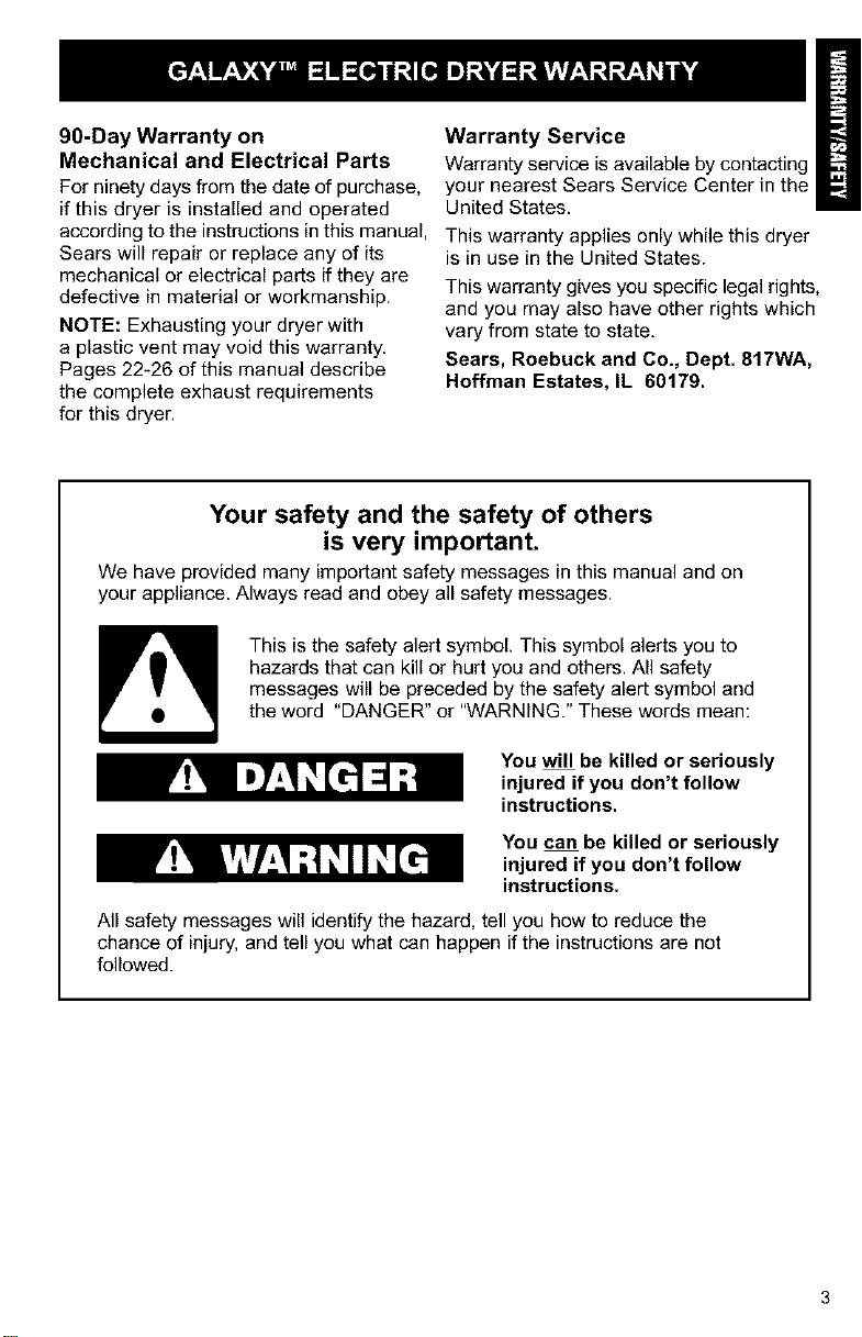
This is the safety alert symbol. This symbol alerts you to
hazards that can kill or hurt you and others. All safety
messages will be preceded by the safety alert symbol and
the word "DANGER" or "WARNING." These words mean:
You will be killed or seriously
injured if you don't follow
instructions.
You can be killed or seriously
injured if you don't follow
instructions.
All safety messages will identify the hazard, tell you how to reduce the
chance of injury, and tell you what can happen if the instructions are not
followed.
IMPORTANT SAFETY INSTRUCTIONS
WARNING : To reduce the risk of fire, electric shock, or injury to persons
when using the dryer, follow basic precautions, including the following:
• Read all instructions before using
the dryer.
• Do not place items exposed to cook-
ing oils in your dryer. Items contami-
nated with cooking oils may contribute
to a chemical reaction that could
cause a load to catch fire.
• Do not dry articles that have been pre-
viously cleaned in, washed in, soaked
in, or spotted with gasoline, dry-clean-
ing solvents, other flammable, or ex-
plosive substances as they give off
vapours that could ignite or explode.
• Do not allow children to play on or in
the dryer. Close supervision of
children is necessary when the dryer
is used near children.
• Before the dryer is removed from ser-
vice or discarded, remove the door to
the drying compartment.
• Do not reach into the dryer if the drum
is moving.
• Do not install or store the dryer where
it will be exposed to the weather.
• Do not tamper with controls.
• Do not repair or replace any part of
the dryer or attempt any servicing
unless specifically recommended in
this Owner's Manual or in
published user-repair instructions
that you understand and have the
skills to carry out.
• Do not use fabric softeners or
products to eliminate static unless
recommended by the manufacturer
of the fabric softener or product.
• Do not use heat to dry articles con-
taining foam rubber or similarly tex-
tured rubber-like materials.
• Clean lint screen before or after
each load.
• Keep area around the exhaust
opening and adjacent surrounding
areas free from the accumulation
of lint, dust, and dirt.
• The interior of the dryer and
exhaust vent should be cleaned
periodically by qualified service
personnel.
• See Installation Instructions for
grounding requirements.
SAVE THESEINSTRUCTIONS
I
IMPORTANT: Observe all governing codes and ordinances.
INSTALLATION OVERVIEW
For a complete list of tools and parts
needed, see pages 5-7.
A. SELECT LOCATION FOR YOUR DRYER (pgs, 8-9)
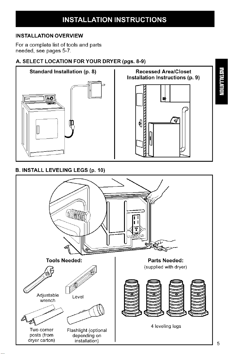
Standard Installation (p. 8) Recessed Area/Closet
Installation Instructions (p, 9)
3
B. INSTALL LEVELING LEGS (p, 10)
Tools Needed:
Adjustable Level
wrench
Two corner Flashlight (optional
posts (from depending on
dryer carton) installation)
Parts Needed:
(supplied with dryer)
4 leveling legs
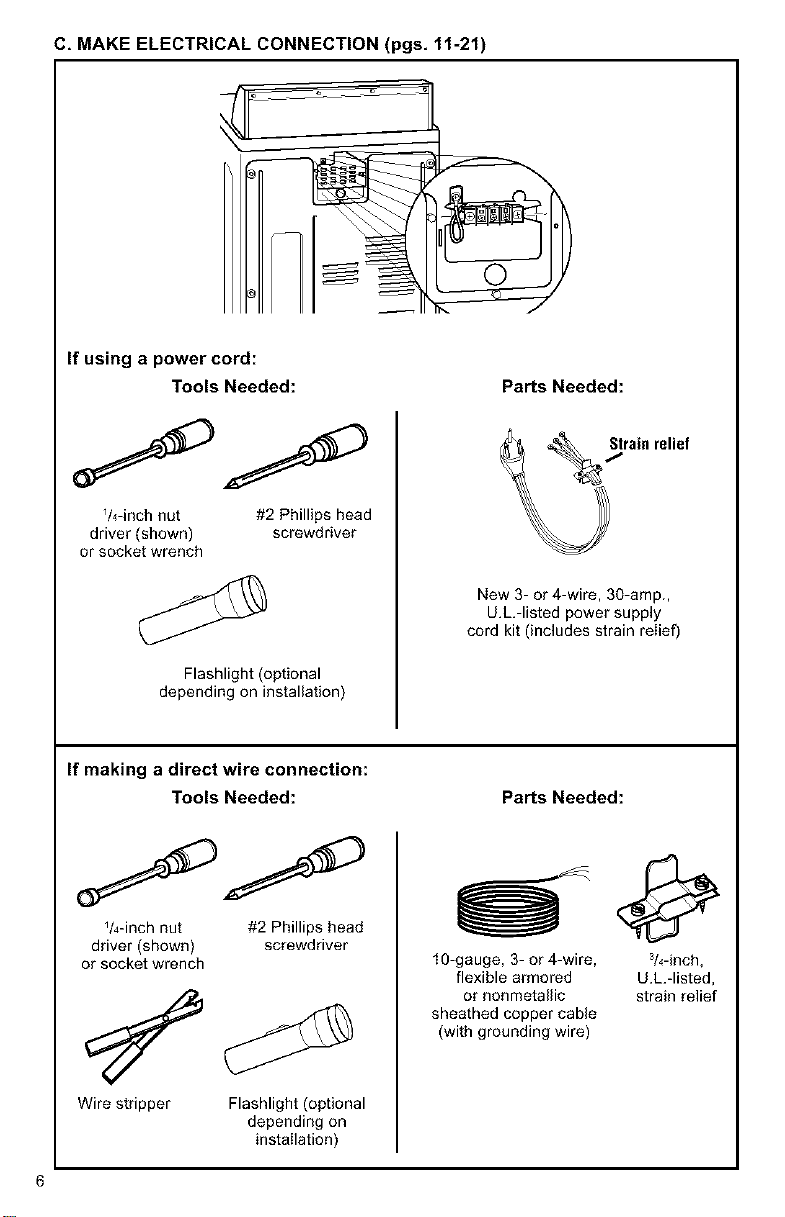
C, MAKE ELECTRICAL CONNECTION (pgs, 11-21)
If using a power cord:
Tools Needed:
V4-inch nut #2 Phillips head
driver (shown) screwdriver
or socket wrench
Flashlight (optional
depending on installation)
PaNs Needed:
New 3- or 4-wire, 30-amp.,
U.L.-listed power supply
cord kit (includes strain relief)
If making a direct wire connection:
Tools Needed:
_/4-inch nut #2 Phillips head
driver (shown) screwdriver
or socket wrench
Wire stripper Flashlight (optional
depending on
installation)
PaNs Needed:
10-gauge, 3- or 4-wire, 3/4-inch,
flexible armored U.L.-listed,
or nonmetallic strain relief
sheathed copper cable
(with grounding wire)
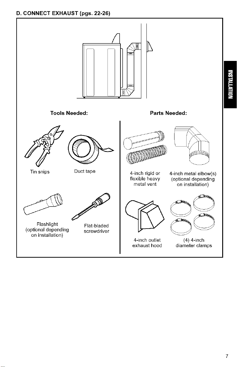
D, CONNECT EXHAUST (pgs. 22-26)
Tools Needed: PaNs Needed:
Tin snips
Flashlight
(optional depending
on installation)
Duct tape
Flat-bladed
screwdriver
4-inch rigid or 4-inch metal elbow(s)
flexible heavy (optional depending
metal vent on installation)
C OO
OO
4-inch outlet (4) 4-inch
exhaust hood diameter clamps
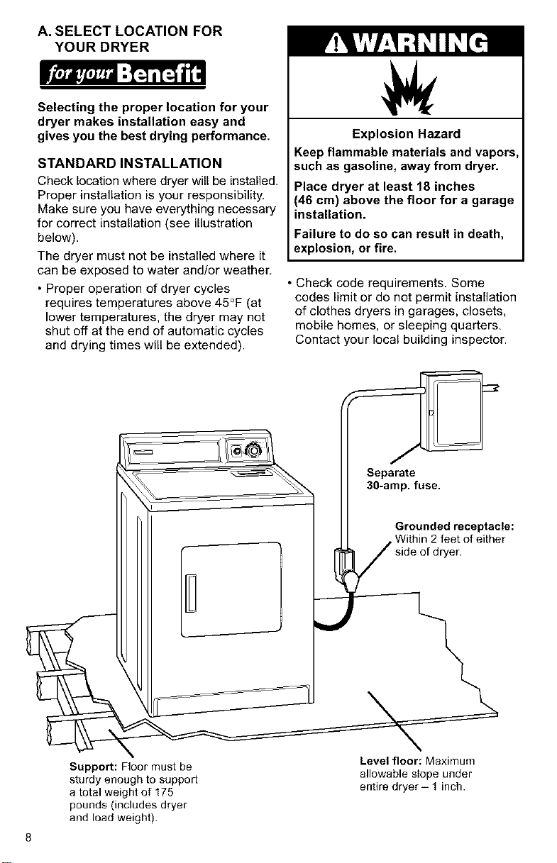
A. SELECT LOCATION FOR
YOUR DRYER
Selecting the proper location for your
dryer makes installation easy and
gives you the best drying performance.
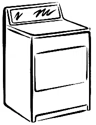
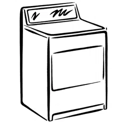
STANDARD INSTALLATION
Check location where dryer will be installed.
Proper installation is your responsibility,
Make sure you have everything necessary
for correct installation (see illustration
below).
The dryer must not be installed where it
can be exposed to water and/or weather.
• Proper operation of dryer cycles
requires temperatures above 45°F (at
lower temperatures, the dryer may not
shut off at the end of automatic cycles
and drying times will be extended).
Explosion Hazard
Keep flammable materials and vapors,
such as gasoline, away from dryer.
Place dryer at least 18 inches
(46 cm) above the floor for a garage
installation.
Failure to do so can result in death,
explosion, or fire.
• Check code requirements, Some
codes limit or do not permit installation
of clothes dryers in garages, closets,
mobile homes, or sleeping quarters,
Contact your local building inspector.
Support: Floor must be
sturdy enough to support
a total weight of 175
pounds (includes dryer
and load weight).
Level floor: Maximum
allowable slope under
entire dryer- 1 inch.
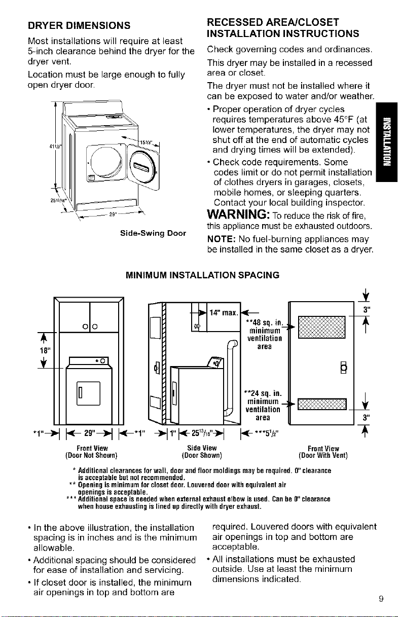
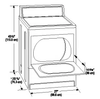
DRYER DIMENSIONS
Most installations will require at least
5-inch clearance behind the dryer for the
dryer vent.
Location must be large enough to fully
open dryer door.
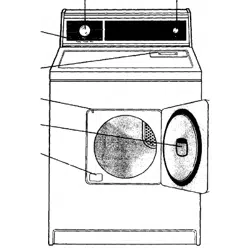
Side-Swing Door
RECESSED AREA/CLOSET
INSTALLATION INSTRUCTIONS
Check governing codes and ordinances.
This dryer may be installed in a recessed
area or closet.
The dryer must not be installed where it
can be exposed to water and/or weather.
• Proper operation of dryer cycles
requires temperatures above 45°F (at
lower temperatures, the dryer may not
shut off at the end of automatic cycles
and drying times will be extended).
• Check code requirements. Some
codes limit or do not permit installation
of clothes dryers in garages, closets,
mobile homes, or sleeping quarters.
Contact your local building inspector.
WARNING: To reduce the risk of fire,
this appliance must be exhausted outdoors.
NOTE: No fuePburning appliances may
be installed in the same closet as a dryer.
18"
"1"-->"
MINIMUM INSTALLATION SPACING
oo
14" nax.
....... sq.in:_
ventilation
area
3"
[_ **24 sq,in.
[_ minimum_
ventilation
urea 3"
.-'1" t*-***sv,"
Front View Side View FrontView
(Door Not Shown) (Door Shown) (Door With Vent)
* Additional clearances for wall, door and floor moldings may be required. O"clearance
isacceptable but not recommended.
** Openingis minimum for closet door.Louvered doorwith equivalent air
openings is acceptable.
* ** Additional space isneeded when external exhaust elbow is used. Canbe O"clearance
when house exhaustingis lined up directly with dryer exhaust.
• In the above illustration, the installation
spacing is in inches and is the minimum
allowable.
• Additional spacing should be considered
for ease of installation and servicing.
• If closet door is installed, the minimum
air openings in top and bottom are
required. Louvered doors with equivalent
air openings in top and bottom are
acceptable.
• All installations must be exhausted
outside. Use at least the minimum
dimensions indicated.
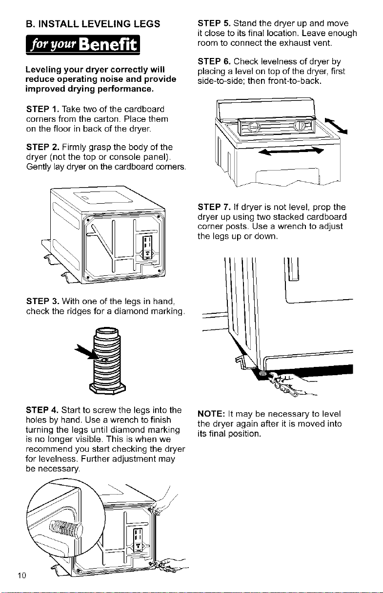
B. INSTALL LEVELING LEGS STEP 5. Stand the dryer up and move
it close to its final location. Leave enough
room to connect the exhaust vent.
Leveling your dryer correctly will
reduce operating noise and provide
improved drying performance.
STEP 1. Take two of the cardboard
corners from the carton, Place them
on the floor in back of the dryer.
STEP 2. Firmly grasp the body of the
dryer (not the top or console panel).
Gently lay dryer on the cardboard corners.
STEP 6. Check levelness of dryer by
placing a level on top of the dryer, first
side4o-side; then front-to-back.
STEP 7. If dryer is not level, prop the
dryer up using two stacked cardboard
corner posts. Use a wrench to adjust
the legs up or down.
STEP 3. With one of the legs in hand,
check the ridges for a diamond marking.
STEP 4. Start to screw the legs into the
holes by hand. Use a wrench to finish
turning the legs until diamond marking
is no longer visible, This is when we
recommend you start checking the dryer
for levelness. Further adjustment may
be necessary.
10
NOTE: It may be necessary to level
the dryer again after it is moved into
its final position.
C. MAKE ELECTRICAL
CONNECTION
It is your responsibility:
• To contact a qualified electrical installer.
• To assure that the electrical installation
is adequate and in conformance with
the National Electrical Code, ANSI/
NFPA 70 - latest edition and all local
codes and ordinances.
Copies of the code standards listed
above may be obtained from:
National Fire Protection Association
Batterymarch Park
Quincy, Massachusetts 02269
ELECTRICAL REQUIREMENTS
The proper electrical connection
ensures a safe installation that
meets local code requirements.
A three-wire or four-wire, single
phase, 120/240-volt, 60*Hz., AC-only,
electrical supply (or three-wire or
four-wire, 120/208-volt if specified on
serial/rating plate) is required on a
separate 30-ampere circuit, fused on
both sides of the line. A time-delay fuse
or circuit breaker is recommended.
This dryer is manufactured with the
3-wire, frame-grounding conductor
connected to the NEUTRAL (white
or center) of the wiring harness of the
terminal block. Do not have a fuse in
the neutral or grounding circuit. Afuse
in the neutral or grounding circuit could
result in an electrical shock.
Use a 4-conductor cord when the
dryer is installed in a mobile home or
an area where local codes do not
permit grounding through the neutral.
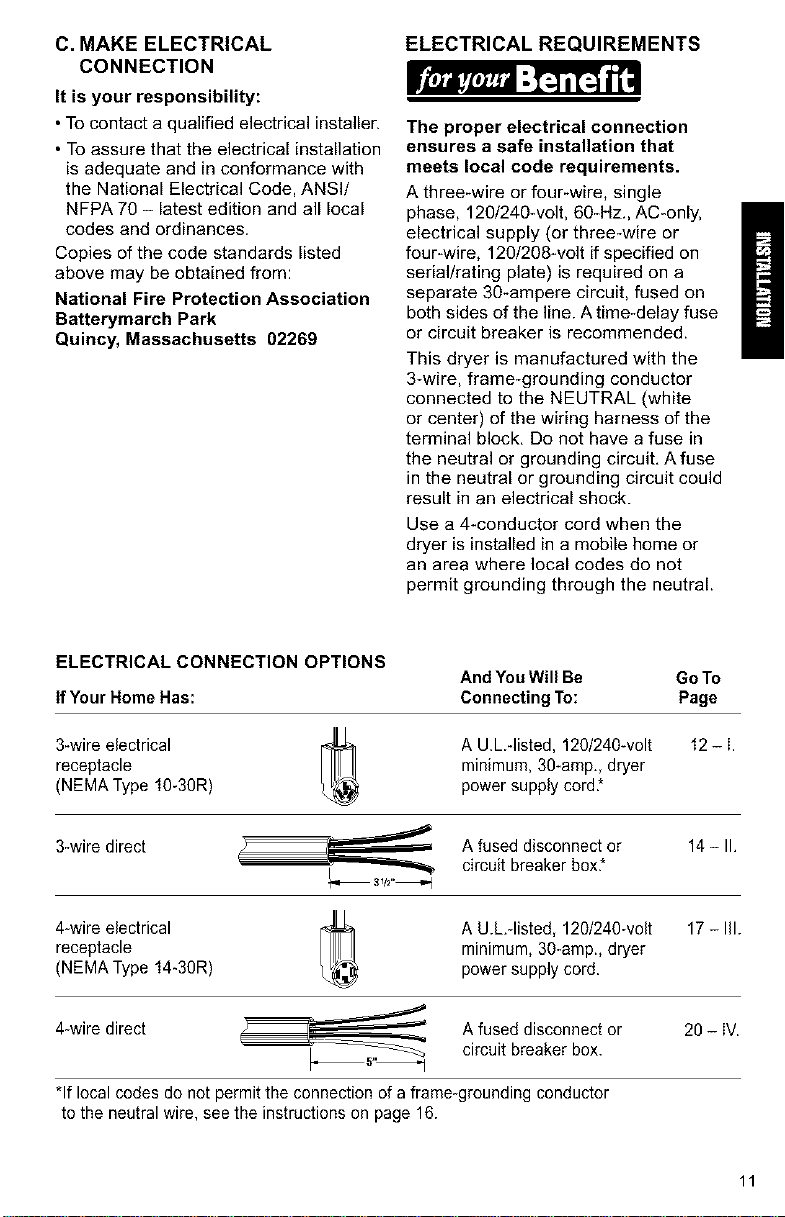
ELECTRICAL CONNECTION OPTIONS
And YouWill Be Go To
IfYour Home Has: Connecting To: Page
3-wire electrical A U.L -listed, 120/240wolt 12 - i.
receptacle minimum, 30-amp., dryer
(NEMA Type 10-30R) power supply cord*
3-wire direct A fused disconnect or 14 - II.
circuit breaker box*
4-wire electrical A U.hqisted, 120/240-volt 17 - Ill.
receptacle minimum, 30-amp., dryer
(NEMA Type 14-30R) power supply cord.
4-wire direct Afused disconnect or 20 - iV.
__ circuit breaker box.
*If local codes do not permit the connection of aframe-grounding conductor
to the neutral wire, see the instructions on page 16.
11
I. THREE-WIRE ELECTRICAL
CONNECTION TO RECEPTACLE
Use a 3-wire power supply cord:
Fire Hazard
Use a new UL approved 30 ampere
power supply cord.
Use a UL approved strain relief,
Disconnect power before making
electrical connections.
Connect neutral wire (white or center
wire) to center terminal (silver).
Ground wire (green or bare wire)
must be connected to green ground
connector,
Connect remaining 2 supply wires
to remaining 2 terminals (gold).
Securely tighten all electrical
connections,
Failure to do so can result in death,
fire, or electrical shock.
Local codes may permit the use of
a U.L.-listed, 120/240-volt minimum,
30*ampere, dryer power supply cord
kit (pigtail). Power supply cord should
be type SRD or SRDT and be at least
four feet long. The wires that connect
to the dryer must end with ring terminals
or spade terminals with upturned ends.
Do not use an extension cord with
this dryer.
Do not connect plug end of power
supply cord into a live receptacle
before connecting power supply cord
to dryer terminal block.
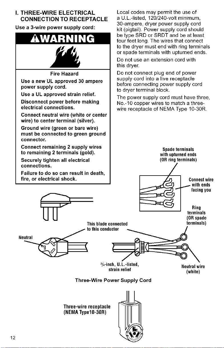
The power supply cord must have three,
No.-10 copper wires to match a three-
wire receptacle of NEMA Type 10-30R.
Spadeterminals
withupturnedends
(ORringterminals)
Connectwire
, ic',ho; d0
Rilg
terminals
(ORspade
Thisbladeconnected terminals)
tothisconductor _ /
3/4-inch,U.L.-listed, Neutralwire
strainrelief (white)
Three-Wire Power Supply Cord
12
Three-wirereceptacle
(NEMATypelO-3OR)
GROUNDING INSTRUCTIONS
This appliance must be grounded,
In the event of malfunction or break-
down, grounding will reduce the risk
of electric shock by providing a path
of least resistance for electric current.
The power supply cord must be plugged
into an appropriate outlet that is properly
installed and grounded in accordance
with all local codes and ordinances.
WARNING: Improper connection of
the equipment-grounding conductor can
result in a risk of electric shock, Check
with a qualified electrician or serviceman
if your are in doubt as to whether the
appliance is properly grounded.
Do not modify the plug on the power
supply cord, If it will not fit the outlet,
have a proper outlet installed by a
qualified electrician.
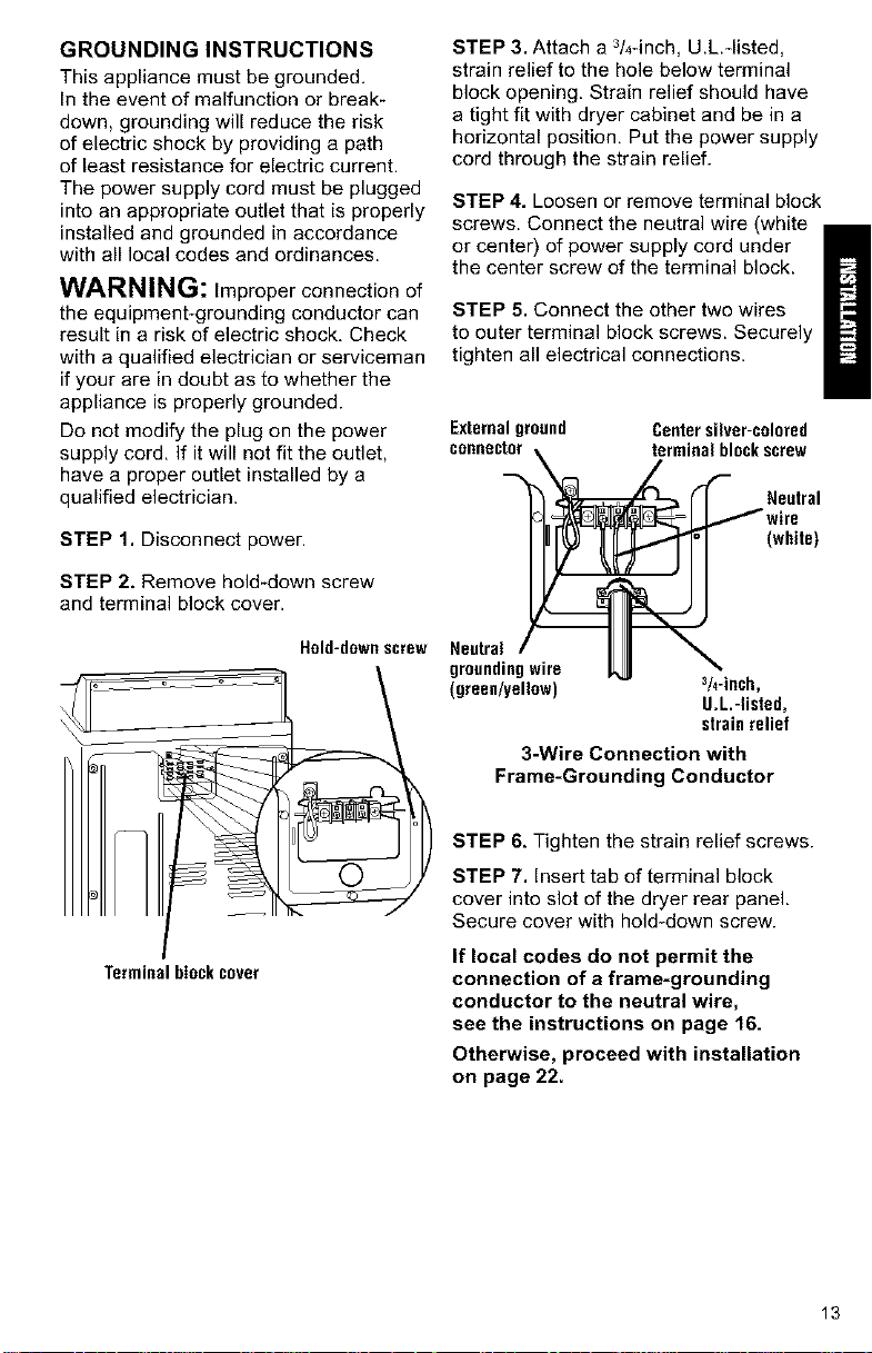
STEP 1. Disconnect power.
STEP 2. Remove hold-down screw
and terminal block cover.
Hold-downscrew
Terminalblockcover
STEP 3. Attach a 3/4-inch, U.L.*listed,
strain relief to the hole below terminal
block opening. Strain relief should have
a tight fit with dryer cabinet and be in a
horizontal position, Put the power supply
cord through the strain relief.
STEP 4. Loosen or remove terminal block
screws. Connect the neutral wire (white
or center) of power supply cord under
the center screw of the terminal block.
STEP 5. Connect the other two wires
to outer terminal block screws. Securely
tighten all electrical connections.
Externalground Centersilver-colored
connector_ ,_erminal blockscrew
"_ _ _- _- Nw;rUetra'
(white)
,eetro,/ II \
groundingwire JL_ "_
(green/yellow) 3/4"inch,
U.L.-listed,
strainrelief
3-Wire Connection with
Frame-Grounding Conductor
STEP 6, Tighten the strain relief screws.
STEP 7. Insert tab of terminal block
cover into slot of the dryer rear panel.
Secure cover with hold-down screw.
If local codes do not permit the
connection of a frame-grounding
conductor to the neutral wire,
see the instructions on page 16.
Otherwise, proceed with installation
on page 22.
13
II. THREE-WIRE ELECTRICAL
CONNECTION (DIRECT WIRE)
Prepare cable as directed:
Fire Hazard
Use 10 gauge solid copper wire.
Use a UL approved strain relief.
Disconnect power before making
electrical connections.
Connect neutral wire (white or center
wire) to center terminal (silver).
Ground wire (green or bare wire)
must be connected to green ground
connector.
Connect remaining 2 supply wires
to remaining 2 terminals (gold).
Securely tighten all electrical
connections.
Failure to follow these instructions
can result in death, fire, or
electrical shock.
The dryer can be connected directly to
fused disconnect or circuit breaker box
with three*wire, flexible armored or non-
metallic sheathed copper cable (with
grounding wire). All current*carrying wires
must be insulated.
A conduit connector must be installed at
junction box. Allow four feet of slack in the
line so dryer can be moved if servicing
is ever necessary.
GROUNDING INSTRUCTIONS
This appliance must be connected to
a grounded metal, permanent wiring
system; or an equipment*grounding
conductor must be run with the circuit
conductors and connected to the
equipment*grounding terminal or
lead on the appliance.
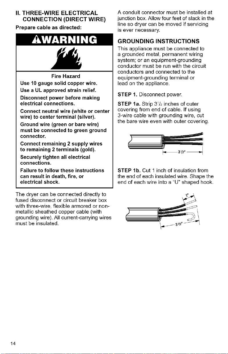
STEP 1, Disconnect power.
STEP la. Strip 3Vz inches of outer
covering from end of cable. If using
3-wire cable with grounding wire, cut
the bare wire even with outer covering.
STEP lb. Cut 1 inch of insulation from
the end of each insulated wire. Shape the
end of each wire into a "U" shaped hook.
14
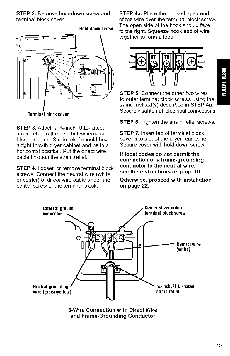
STEP 2. Remove hold-down screw and
terminal block cover.
Held-downscrew
Terminal block cover
STEP 3. Attach a 3/4-inch, U.L.-listed,
strain relief to the hole below terminal
block opening, Strain relief should have
a tight fit with dryer cabinet and be in a
horizontal position. Put the direct wire
cable through the strain relief.
STEP 4. Loosen or remove terminal block
screws. Connect the neutral wire (white
or center) of direct wire cable under the
center screw of the terminal block.
STEP 4a. Place the hook-shaped end
of the wire over the terminal block screw.
The open side of the hook should face
to the right. Squeeze hook end of wire
together to form a loop.
STEP 5. Connect the other two wires
to outer terminal block screws using the
same method(s) described in STEP 4a,
Securely tighten all electrical connections.
STEP 6. Tighten the strain relief screws.
STEP 7. Insert tab of terminal block
cover into slot of the dryer rear panel.
Secure cover with hold-down screw.
If local codes do not permit the
connection of a frame-grounding
conductor to the neutral wire,
see the instructions on page 16.
Otherwise, proceed with installation
on page 22.
Externalground
connector
Neutral grounding,
wire (green/yellow
_ Centersilver-colored
terminalblockscrew
In r'([_ _'_ _ _ _ Neutralwire
IIII ,,.,ecb,0L-,sted,
JJ_J strainrelief
3-Wire Connection with Direct Wire
and Frame-Grounding Conductor
15
ALTERNATE CONNECTION:
If local codes do not permit the
connection of a frame-grounding
conductor to the neutral wire:
STEP 1. Disconnect power.
STEP 2. Make sure the power supply
cord or direct wire cable is in place
(see STEPS 1-3 on page 13 for power
cord connections or STEPS 1-3 on
pages 14-15 for direct wire connection),
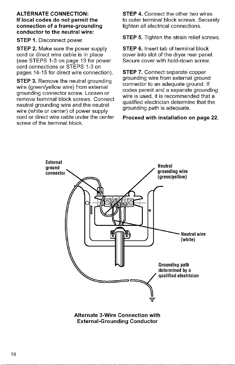
STEP 3. Remove the neutral grounding
wire (green/yellow wire) from external
grounding connector screw, Loosen or
remove terminal block screws. Connect
neutral grounding wire and the neutral
wire (white or center) of power supply
cord or direct wire cable under the center
screw of the terminal block.
STEP 4. Connect the other two wires
to outer terminal block screws. Securely
tighten all electrical connections.
STEP 5, Tighten the strain relief screws.
STEP 6. Insert tab of terminal block
cover into slot of the dryer rear panel.
Secure cover with hold-down screw.
STEP 7, Connect separate copper
grounding wire from external ground
connector to an adequate ground, If
codes permit and a separate grounding
wire is used, it is recommended that a
qualified electrician determine that the
grounding path is adequate.
Proceed with installation on page 22.
External
ground
Neutral
groundingwire
(green/yellow)
Neutralwire
(white)
Groundingpath
determined by a
ualified electrician
Alternate 3-Wire Connection with
External-Grounding Conductor
16
III. MAKE FOUR-WIRE
ELECTRICAL CONNECTION
TO RECEPTACLE
Usea 4-wire power supply cord:
Fire Hazard
Use a new UL approved 30 ampere
power supply cord.
Use a UL approved strain relief.
Disconnect power before making
electrical connections.
Connect neutral wire (white or center
wire) to center terminal (silver).
Ground wire (green or bare wire)
must be connected to green ground
connector.
Connect remaining 2 supply wires
to remaining 2 terminals (gold).
Securely tighten all electrical
connections.
Failure to do so can result in death,
fire, or electrical shock,
Neutral
Local codes may permit the use of
a U.L.qisted, 120/240-volt minimum,
30-ampere, dryer power supply cord kit
(pigtail). Power supply cord should be
type SRD or SRDT and be at least four
feet long. The wires that connect to the
dryer must end with ring terminals or
spade terminals with upturned ends.
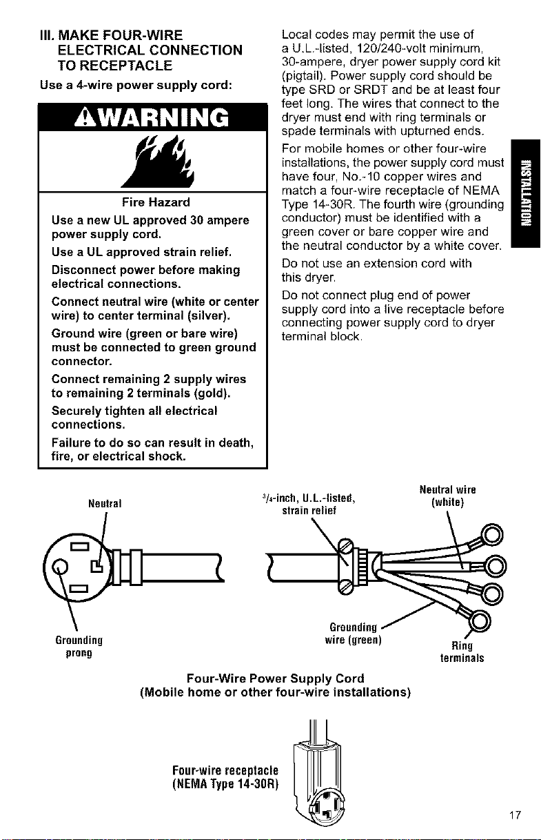
For mobile homes or other four-wire
installations, the power supply cord must
have four, No.-10 copper wires and
match a four-wire receptacle of NEMA
Type 14_30R. The fourth wire (grounding
conductor) must be identified with a
green cover or bare copper wire and
the neutral conductor by a white cover.
Do not use an extension cord with
this dryer.
Do not connect plug end of power
supply cord into a live receptacle before
connecting power supply cord to dryer
terminal block.
Neutralwire
3/4-inch,g.L.-listed, (white)
strainrelief
Grounding
prong
Grounding
wire (green)
Four-Wire Power Supply Cord
(Mobile home or other four-wire installations)
Four-wirereceptacle
(NEMAType14-30R)
Ring
terminals
17

GROUNDING INSTRUCTIONS
This appliance must be grounded.
In the event of malfunction or break-
down, grounding will reduce the risk
of electric shock by providing a path of
least resistance for electric current. The
power supply cord must be plugged into
an appropriate outlet that is properly
installed and grounded in accordance
with all local codes and ordinances.
WARNING: Improper connection of
the equipment-grounding conductor can
result in a risk of electric shock. Check
with a qualified electrician or serviceman
if you are in doubt as to whether the
appliance is properly grounded.
Do not modify the plug on the power
supply cord. If it will not fit the outlet,
have a proper outlet installed by a
qualified electrician.
STEP 1. Disconnect power.
STEP 2. Remove hold-down screw
and terminal block cover.
Held-downscrew
STEP 3. Attach a 3/4-inch, U.L.qisted,
strain relief to the hole below terminal
block opening. Strain relief should have
a tight fit with dryer cabinet and be in a
horizontal position. Put the power supply
cord through the strain relief.
STEP 4. Remove the center terminal
block screw. Remove the neutral ground-
ing wire (green/yellow wire) from external
grounding screw.
Externalground
connector
Centersilver-colored
terminal blockscrew
©
Green/yellowwire
ofharness
}
Terminalblockcover
18
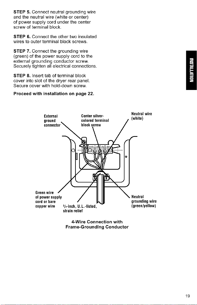
STEP 5. Connect neutral grounding wire
and the neutral wire (white or center)
of power supply cord under the center
screw of terminal block.
STEP 6. Connect the other two insulated
wires to outer terminal block screws.
STEP 7. Connect the grounding wire
(green) of the power supply cord to the
external grounding conductor screw.
Securely tighten all electrical connections.
STEP 8. Insert tab of terminal block
cover into slot of the dryer rear panel.
Secure cover with hold-down screw.
Proceed with installation on page 22.
External Center silveP
ground coleredterminal
bleckscrew
Neutral wire
(white)
Green wire
of power supply
cord orbare
copper wire 3h-inch, g.L.-Iinted,
strain relief
4-Wire Connection with
Frame-Grounding Conductor
Neutral
groundingwire
(green/yell0w)
19
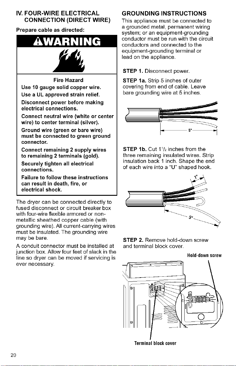
IV. FOUR-WIRE ELECTRICAL
CONNECTION (DIRECT WIRE)
Prepare cable as directed:
Fire Hazard
Use 10 gauge solid copper wire.
Use a UL approved strain relief.
Disconnect power before making
electrical connections.
Connect neutral wire (white or center
wire) to center terminal (silver).
Ground wire (green or bare wire)
must be connected to green ground
connector.
Connect remaining 2 supply wires
to remaining 2 terminals (gold).
Securely tighten all electrical
connections.
Failure to follow these instructions
can result in death, fire, or
electrical shock.
The dryer can be connected directly to
fused disconnect or circuit breaker box
with four-wire flexible armored or non-
metallic sheathed copper cable (with
grounding wire). All current-carrying wires
must be insulated. The grounding wire
may be bare.
A conduit connector must be installed at
junction box, Allow four feet of slack in the
line so dryer can be moved if servicing is
ever necessary.
GROUNDING INSTRUCTIONS
This appliance must be connected to
a grounded metal, permanent wiring
system; or an equipment-grounding
conductor must be run with the circuit
conductors and connected to the
equipment-grounding terminal or
lead on the appliance.
STEP 1. Disconnect power.
STEP la. Strip 5 inches of outer
covering from end of cable. Leave
bare grounding wire at 5 inches.
_r _
STEP lb. Cut 1V2 inches from the
three remaining insulated wires, Strip
insulation back 1 inch. Shape the end
of each wire into a "U" shaped hook.
STEP 2. Remove hold-down screw
and terminal block cover.
Hold-downscrew
Terminalblockcover
2O
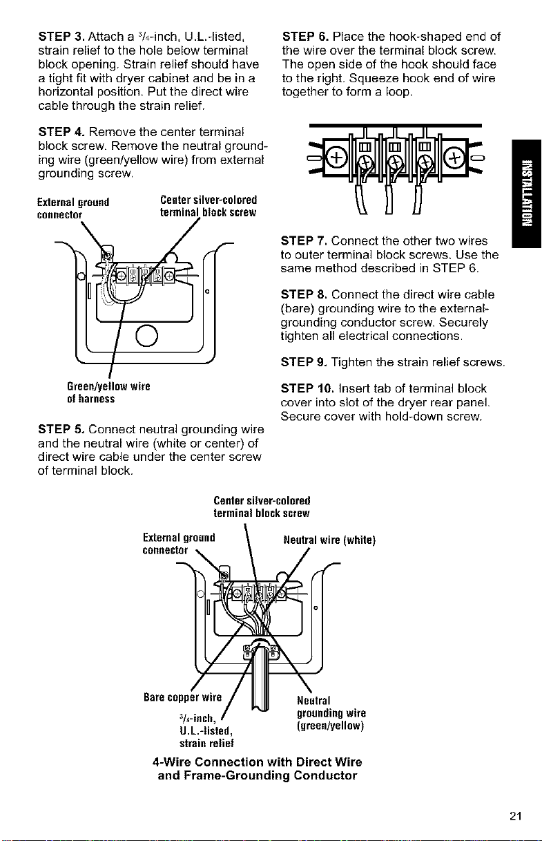
STEP 3. Attach a 3/4-inch, U.L.-listed,
strain relief to the hole below terminal
block opening. Strain relief should have
a tight fit with dryer cabinet and be in a
horizontal position. Put the direct wire
cable through the strain relief.
STEP 4. Remove the center terminal
block screw, Remove the neutral ground-
ing wire (green/yellow wire) from external
grounding screw.
STEP 6. Place the hook-shaped end of
the wire over the terminal block screw.
The open side of the hook should face
to the right. Squeeze hook end of wire
together to form a loop.
Externalground
connector
Centersilver-colored
terminalbIockscrew
/
©
Green/yellow wire
of harness
STEP 5. Connect neutral grounding wire
and the neutral wire (white or center) of
direct wire cable under the center screw
of terminal block.
STEP 7, Connect the other two wires
to outer terminal block screws. Use the
same method described in STEP 6.
STEP 8, Connect the direct wire cable
(bare) grounding wire to the external-
grounding conductor screw. Securely
tighten all electrical connections.
STEP 9, Tighten the strain relief screws.
STEP 10, Insert tab of terminal block
cover into slot of the dryer rear panel.
Secure cover with hold-down screw.
Center silver-colored
terminal blockscrew
Externalground
connector
Neutral wire (white)
Bare copper wire
3/4-inch,
U.L.-Iisted,
strain relief
Neutral
groundingwire
(green/yellow)
4-Wire Connection with Direct Wire
and Frame-Grounding Conductor
21
D. CONNECTEXHAUST
A properly exhausted dryer will give
you the shortest drying time, lower
your utility bills, and extend the life
of the dryer,
Fire Hazard
Use a heavy metal vent.
Do not use a plastic vent.
Do not use a metal foil vent.
Failure to follow these instructions
can result in death or fire,
WARNING: xo reduce the risk of
fire, this dryer must be exhausted out-
doors,
• Use a heavy metal vent.
• Do not use a plastic vent.
• Do not use a metal foil vent.
• Do not exhaust dryer into a chimney,
a wall, a ceiling, or a concealed space
of a building.
• The diameter of the heavy metal vent
must be 4 inches.
• Do not use an exhaust hood with a
magnetic latch.
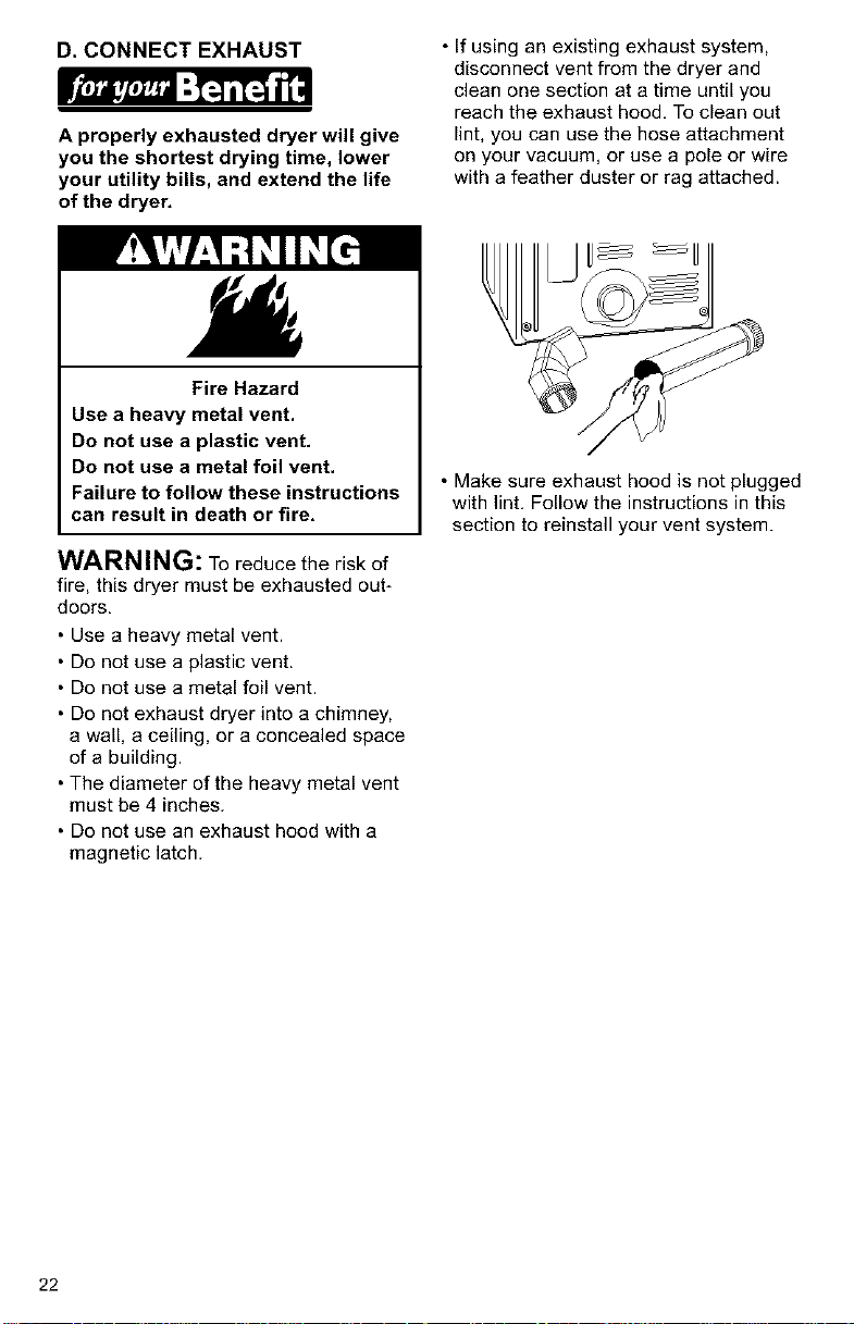
• If using an existing exhaust system,
disconnect vent from the dryer and
clean one section at a time until you
reach the exhaust hood, To clean out
lint, you can use the hose attachment
on your vacuum, or use a pole or wire
with a feather duster or rag attached.
• Make sure exhaust hood is not plugged
with lint, Follow the instructions in this
section to reinstall your vent system.
22
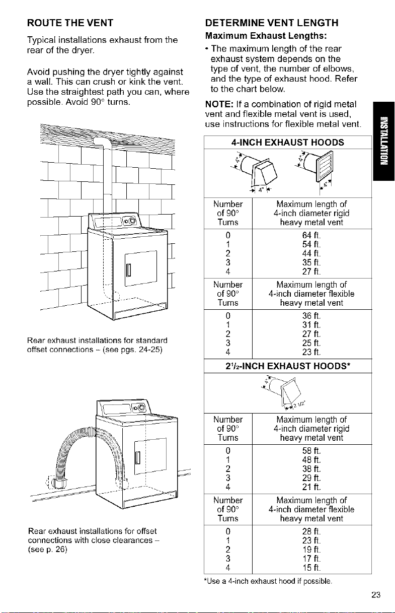
ROUTE THE VENT
Typical installations exhaust from the
rear of the dryer.
Avoid pushing the dryer tightly against
a wall, This can crush or kink the vent,
Use the straightest path you can, where
possible. Avoid 90° turns.
Rear exhaust installations for standard
offset connections - (see pgs. 24-25)
Rear exhaust installations for offset
connections with close clearances -
(see p. 26)
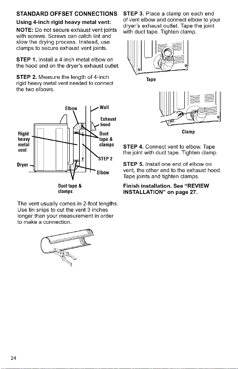
DETERMINE VENT LENGTH
Maximum Exhaust Lengths:
• The maximum length of the rear
exhaust system depends on the
type of vent, the number of elbows,
and the type of exhaust hood. Refer
to the chart below.
NOTE: If a combination of rigid metal
vent and flexible metal vent is used,
use instructions for flexible metal vent.
4-INCH EXHAUST HOODS
Number Maximum length of
of 90° 4-inch diameter rigid
Turns heavy metal vent
O 64 ft.
1 54 ft.
2 44 ft.
3 35 ft.
4 27 ft.
Number Maximum length of
of 90° 4-inch diameter flexible
Turns heavy metal vent
0 36 ft.
1 31 ft.
2 27 ft.
3 25 ft.
4 23 ft.
2V2-1NCH EXHAUST HOODS*
Number Maximum length of
of 90° 4-inch diameter rigid
Turns heavy metal vent
0 58 ft.
1 48 ft.
2 38 ft.
3 29 ft.
4 21 ft.
Number Maximum length of
of 90° 4-inch diameter flexible
Turns heavy metal vent
O 28 ft.
1 23 ft.
2 19ft.
3 17ft.
4 15ft.
*Usea 4-inchexhausthoodif possible.
23
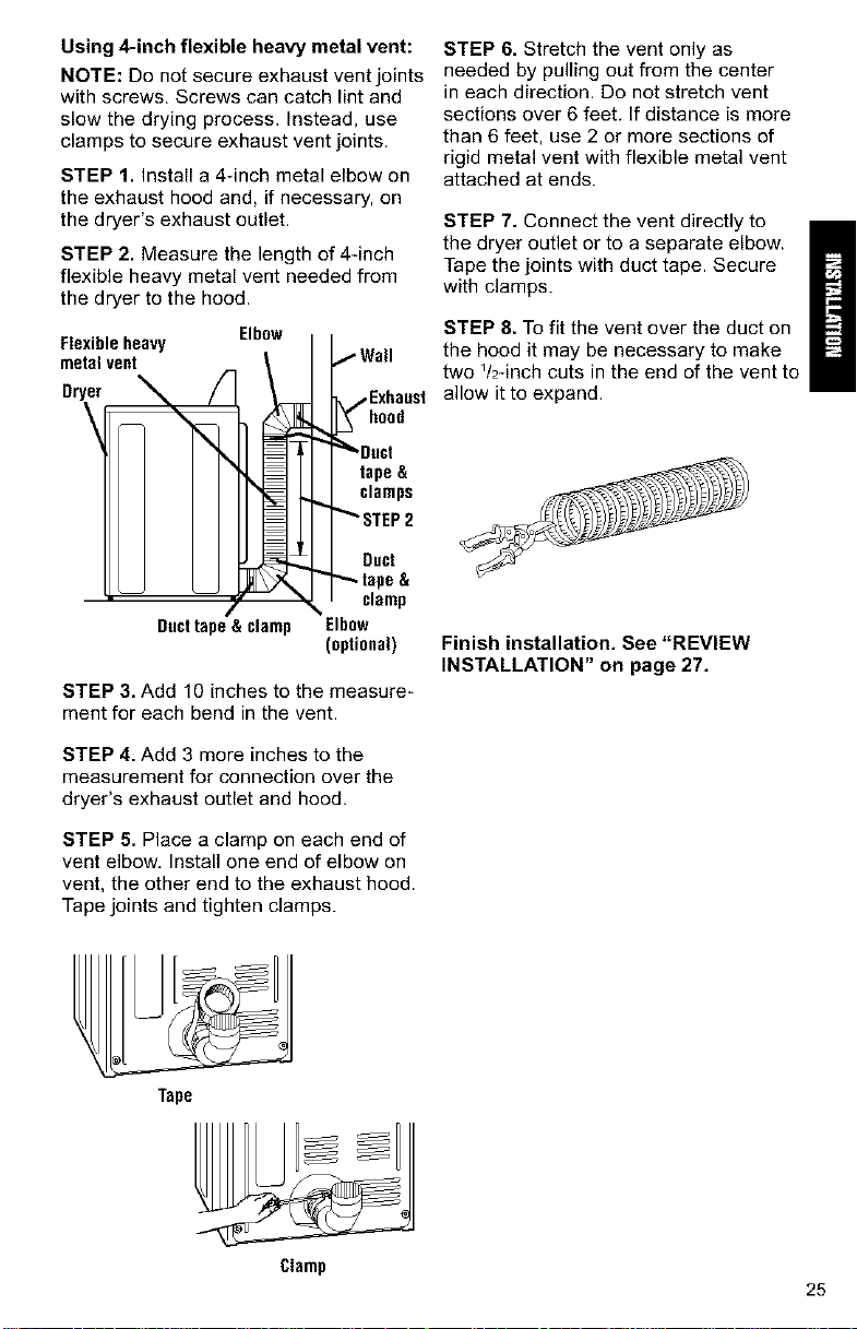
STANDARD OFFSET CONNECTIONS
Using 4-inch rigid heavy metal vent:
NOTE: Do not secure exhaust vent joints
with screws. Screws can catch lint and
slow the drying process. Instead, use
clamps to secure exhaust vent joints.
STEP 1. Install a 4_inch metal elbow on
the hood and on the dryer's exhaust outlet.
STEP 2. Measure the length of 4-inch
rigid heavy metal vent needed to connect
the two elbows.
Rigid
heavy
metal
voot
Dryer-
Elbow
/Wall
Exhaust
_,,,,hood
_Duct
tape &
clamps
_%_STEP2
_" Elbow
Dacttape&
clamps
The vent usually comes in 2-foot lengths.
Use tin snips to cut the vent 3 inches
longer than your measurement in order
to make a connection.
STEP 3. Place a clamp on each end
of vent elbow and connect elbow to your
dryer's exhaust outlet, Tape the joint
with duct tape. Tighten clamp.
Tape
Clamp
STEP 4. Connect vent to elbow. Tape
the joint with duct tape. Tighten clamp.
STEP 5. Install one end of elbow on
vent, the other end to the exhaust hood.
Tape joints and tighten clamps.
Finish installation. See "REVIEW
INSTALLATION" on page 27.
24
Using 4-inch flexible heavy metal vent:
NOTE: Do not secure exhaust vent joints
with screws, Screws can catch lint and
slow the drying process. Instead, use
clamps to secure exhaust vent joints.
STEP 1. Install a 4-inch metal elbow on
the exhaust hood and, if necessary, on
the dryer's exhaust outlet.
STEP 2. Measure the length of 44nch
flexible heavy metal vent needed from
the dryer to the hood.
Flexibleheavy Elbow
metalvent
Dryer
\
Ducttape& clamp
,Exhaast
tape &
clamps
Duct
clamp
Elbow
(optional)
STEP 3. Add 10 inches to the measure-
ment for each bend in the vent.
STEP 4. Add 3 more inches to the
measurement for connection over the
dryer's exhaust outlet and hood.
STEP 5. Place a clamp on each end of
vent elbow, Install one end of elbow on
vent, the other end to the exhaust hood.
Tape joints and tighten clamps.
STEP 6. Stretch the vent only as
needed by pulling out from the center
in each direction. Do not stretch vent
sections over 6 feet, If distance is more
than 6 feet, use 2 or more sections of
rigid metal vent with flexible metal vent
attached at ends.
STEP 7. Connect the vent directly to
the dryer outlet or to a separate elbow.
Tape the joints with duct tape. Secure
with clamps.
STEP 8. To fit the vent over the duct on
the hood it may be necessary to make
two Y2-inch cuts in the end of the vent to
allow it to expand.
Finish installation. See "REVIEW
INSTALLATION" on page 27,
Tape
Clamp
25
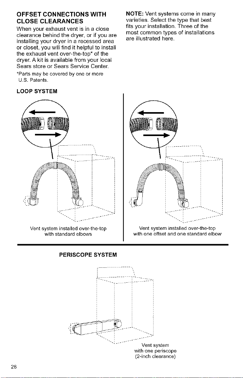
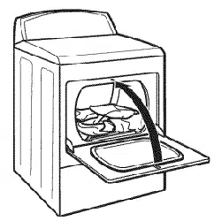
OFFSET CONNECTIONS WITH
CLOSE CLEARANCES
When your exhaust vent is in a close
clearance behind the dryer, or if you are
installing your dryer in a recessed area
or closet, you will find it helpful to install
the exhaust vent over-the4op* of the
dryer. A kit is available from your local
Sears store or Sears Service Center.
*Pads may be covered by one or more
U.S. Patents.
LOOP SYSTEM
NOTE: Vent systems come in many
varieties. Select the type that best
fits your installation. Three of the
most common types of installations
are illustrated here.
Vent system installed over-the-top
with standard elbows
_ i_ _°__ _ _;-J
Vent system installed over-the-top
with one offset and one standard elbow
PERISCOPE SYSTEM
26
Vent system
with one periscope
(2-inch clearance)
REVIEW INSTALLATION
Take a few minutes to complete
this checklist. It will help assure you
that you have a proper installation
and increase your satisfaction with
your Galaxy TM dryer,
[ Check that all parts you removed
from the parts packages are now
installed.
[ Ensure that dryer is positioned in its
final location. Make sure vent is not
crushed or kinked.
I Ensure that dryer is level by placing
a level on top of the dryer. Check side-
to-side first, then check front4o-back.
If dryer is not level, adjust the legs up
or down,
Check to make sure you have all
the tools you started with.
FINAL STEPS
I Plug the power supply cord into the
grounded outlet or connect direct
wire to power supply.
I Turn power supply on.
I Wipe the interior of the drum
thoroughly with a damp cloth to
remove any dust.
I Remove the blue protective film on
the console and any tape remaining
on dryer.
Take a few minutes and read the
Operating Instructions (pgs. 28-29)
to fully understand your new dryer.
Start the dryer and allow it to
complete a full heat cycle. After five
minutes, open dryer door. You should
feel heat inside the dryer. If you do not
feel heat, see "TROUBLESHOOTING"
on pages 33-34.
NOTE: You may notice a burning odor.
This smell is common when the heating
element is first used. The smell will go
away.
27
STARTING YOUR DRYER
Explosion Hazard
Keep flammable materials and
vapors, such as gasoline, away
from dryer.
Do not dry anything that has ever
had anything flammable on it (even
after washing).
Failure to follow these instructions
can result in death, explosion,
or fire.
To get the best drying results, you must
operate your dryer properly. This section
gives you this important information,
NOTE: For more information, refer to
the "Feature Sheet" supplied with your
dryer.
STEP 1. Check lint screen. Clean
if needed.
STEP 2. Put laundry into dryer and
shut door.
Fire Hazard
No washer can completely
remove oil.
Do not dry anything that has ever
had any type of oil on it (including
cooking oils).
Items containing foam, rubber,
or plastic must be dried on a
clothesline or by using an air cycle.
Failure to follow these instructions
can result in death or fire.
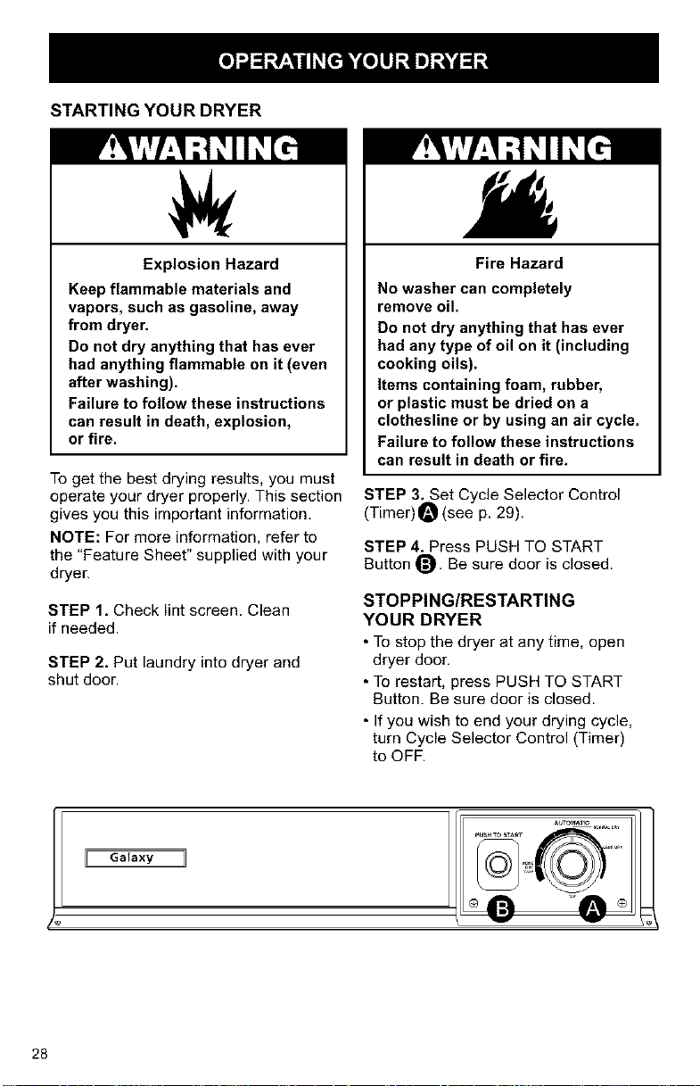
STEP 3. Set Cycle Selector Control
(Timer) O (see p. 29).
STEP 4. Press PUSH TO START
Button O. Be sure door is closed.
STOPPING/RESTARTING
YOUR DRYER
• To stop the dryer at any time, open
dryer door,
• To restart, press PUSH TO START
Button. Be sure door is closed.
• If you wish to end your drying cycle,
turn Cycle Selector Control (Timer)
to OFF.
Galaxy 11
28
CYCLE DESCRIPTION
The AUTOMATIC Cycle saves you time
by providing the best drying results
in the shortest time. This can help
you save money on utility bills and
reduce the risk of fabric damage,
AUTOMATIC CYCLE
This cycle is for sturdy clothes or syn-
thetic, permanent press items. Clothes
are dried at high heat. When the dryness
selected is reached, the dryer goes into
a 5-minute (approx.) cool down period.
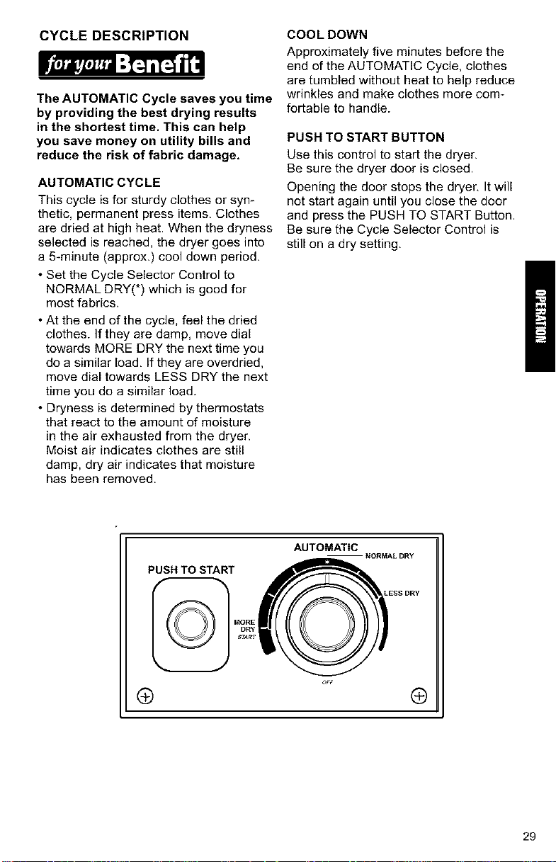
• Set the Cycle Selector Control to
NORMAL DRY(*) which is good for
most fabrics.
• At the end of the cycle, feel the dried
clothes. If they are damp, move dial
towards MORE DRY the next time you
do a similar load. If they are overdried,
move dial towards LESS DRY the next
time you do a similar load.
• Dryness is determined by thermostats
that react to the amount of moisture
in the air exhausted from the dryer.
Moist air indicates clothes are still
damp, dry air indicates that moisture
has been removed.
COOLDOWN
Approximately five minutes before the
end of the AUTOMATIC Cycle, clothes
are tumbled without heat to help reduce
wrinkles and make clothes more corn-
fortable to handle.
PUSH TO START BUTTON
Use this control to start the dryer.
Be sure the dryer door is closed.
Opening the door stops the dryer, It will
not start again until you close the door
and press the PUSH TO START Button.
Be sure the Cycle Selector Control is
still on a dry setting.
PUSH TO START
AUTOMATIC
ESS DRY
® ®
29
This section explains how to care for To clean dryer drum:
your dryer properly and safely.
Proper care of your fryer can extend
its life and help you avoid costly
service calls.
CLEANING THE DRYER
EXTERIOR
USE a soft, damp cloth to clean the
cabinet and console, Avoid using harsh
abrasives. Don not put sharp metal
objects on or in your fryer. They can
damage the finish.
INTERIOR
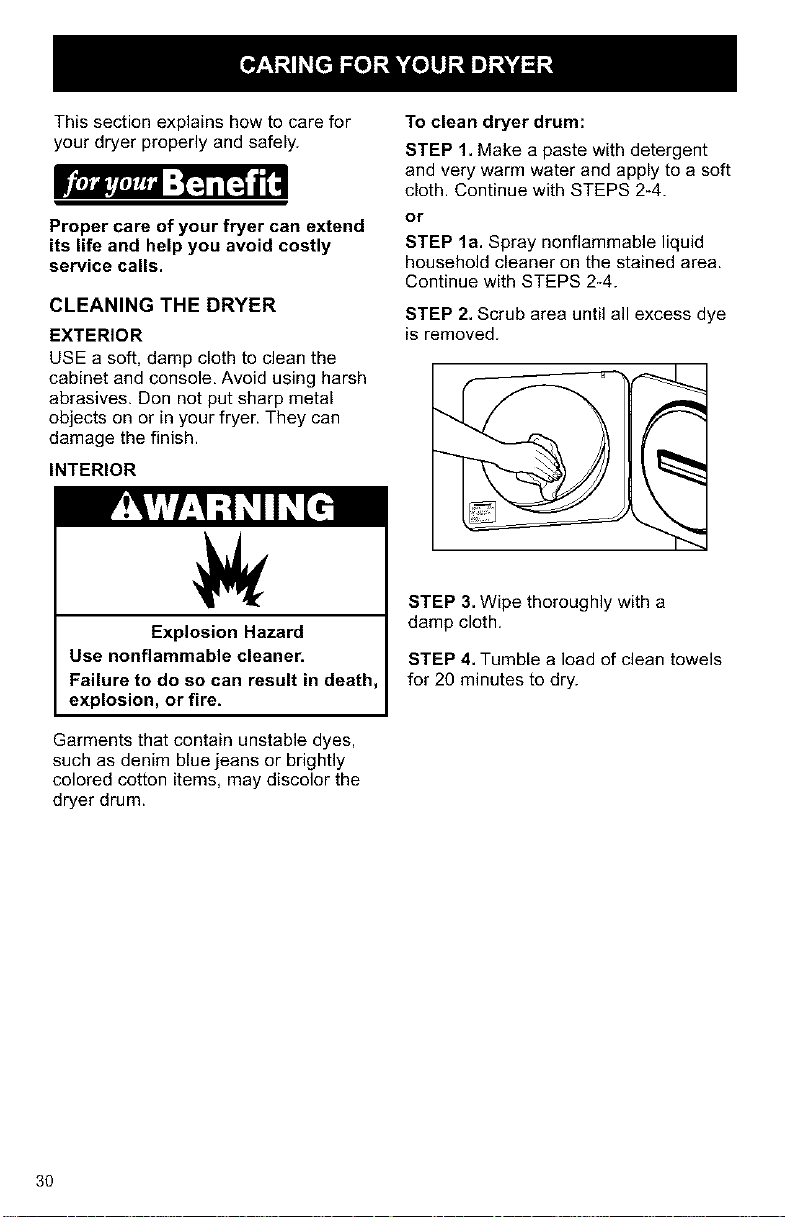
STEP 1. Make a paste with detergent
and very warm water and apply to a soft
cloth. Continue with STEPS 2-4.
or
STEP la. Spray nonflammable liquid
household cleaner on the stained area.
Continue with STEPS 2-4.
STEP 2. Scrub area until all excess dye
is removed.
Explosion Hazard
Use nonflammable cleaner.
Failure to do so can result in death,
explosion, or fire.
Garments that contain unstable dyes,
such as denim blue jeans or brightly
colored cotton items, may discolor the
dryer drum.
STEP 3. Wipe thoroughly with a
damp cloth.
STEP 4. Tumble a load of clean towels
for 20 minutes to dry.
3O
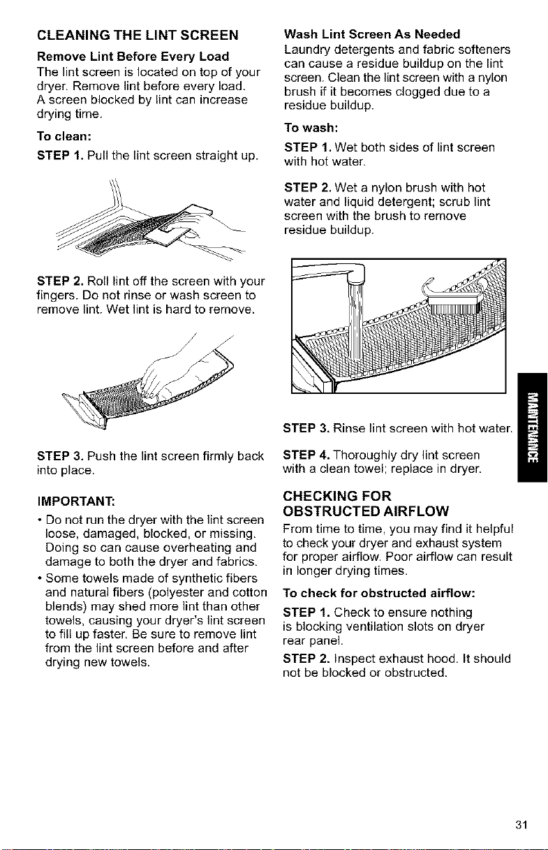
CLEANING THE LINT SCREEN
Remove Lint Before Every Load
The lint screen is located on top of your
dryer, Remove lint before every load.
A screen blocked by lint can increase
drying time.
To clean:
STEP 1, Pull the lint screen straight up.
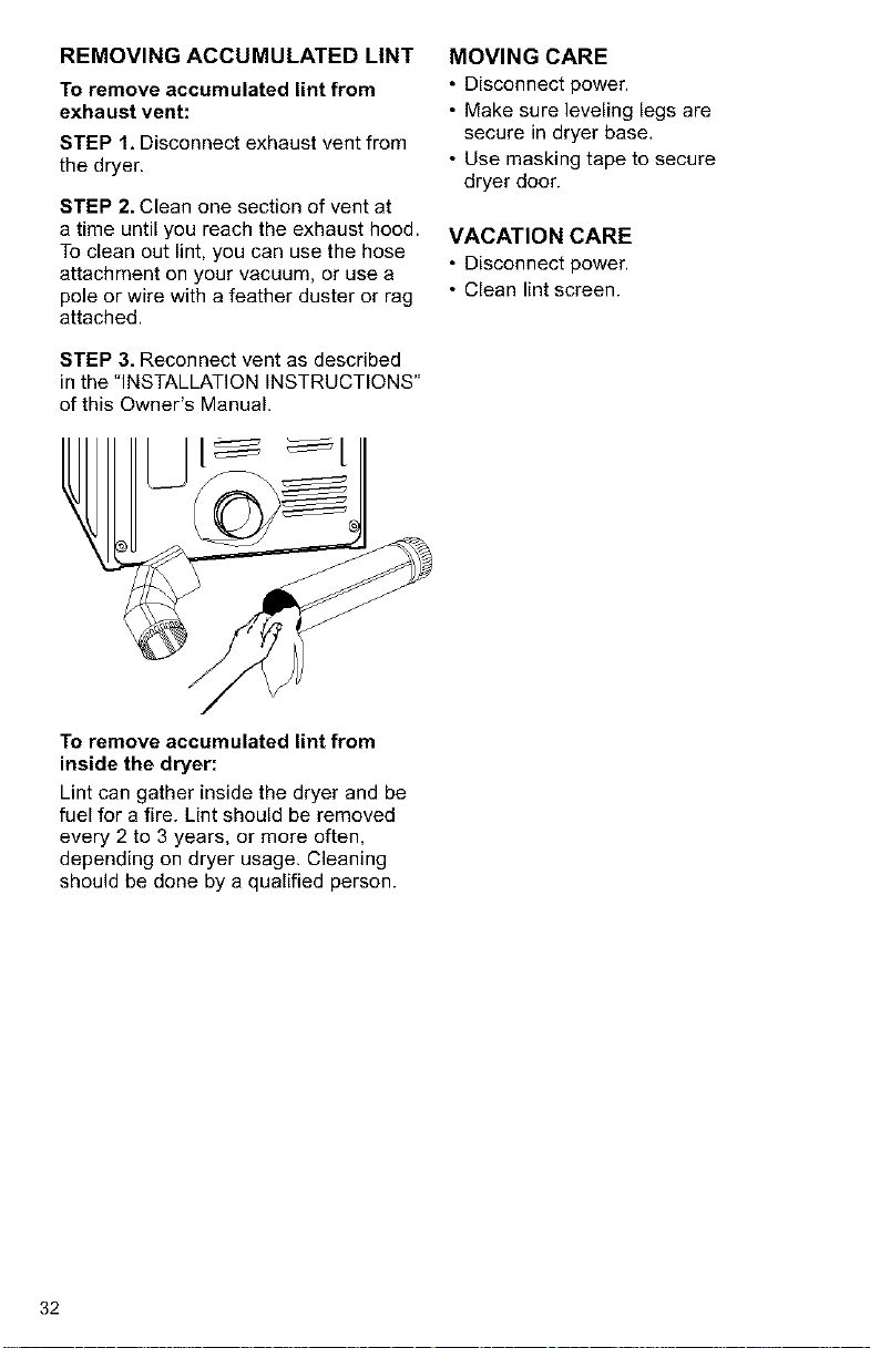
Wash Lint Screen As Needed
Laundry detergents and fabric softeners
can cause a residue buildup on the lint
screen. Clean the lint screen with a nylon
brush if it becomes clogged due to a
residue buildup.
To wash:
STEP 1. Wet both sides of lint screen
with hot water.
STEP 2. Wet a nylon brush with hot
water and liquid detergent; scrub lint
screen with the brush to remove
residue buildup.
STEP 2. Roll lint off the screen with your
fingers. Do not rinse or wash screen to
remove lint. Wet lint is hard to remove.
STEP 3. Push the lint screen firmly back
into place.
IMPORTANT:
• Do not run the dryer with the lint screen
loose, damaged, blocked, or missing,
Doing so can cause overheating and
damage to both the dryer and fabrics,
• Some towels made of synthetic fibers
and natural fibers (polyester and cotton
blends) may shed more lint than other
towels, causing your dryer's lint screen
to fill up faster, Be sure to remove lint
from the lint screen before and after
drying new towels.
STEP 3, Rinse lint screen with hot water.
STEP 4. Thoroughly dry lint screen
with a clean towel; replace in dryer.
CHECKING FOR
OBSTRUCTED AIRFLOW
From time to time, you may find it helpful
to check your dryer and exhaust system
for proper airflow. Poor airflow can result
in longer drying times.
To check for obstructed airflow:
STEP 1. Check to ensure nothing
is blocking ventilation slots on dryer
rear panel.
STEP 2. Inspect exhaust hood. It should
not be blocked or obstructed.
31
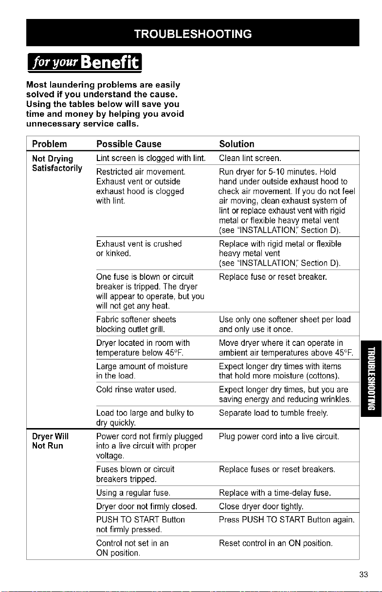
REMOVING ACCUMULATED LINT
To remove accumulated lint from
exhaust vent:
STEP 1. Disconnect exhaust vent from
the dryer.
STEP 2. Clean one section of vent at
a time until you reach the exhaust hood.
To clean out lint, you can use the hose
attachment on your vacuum, or use a
pole or wire with a feather duster or rag
attached.
STEP 3. Reconnect vent as described
in the "INSTALLATION INSTRUCTIONS"
of this Owner's Manual.
MOVING CARE
• Disconnect power.
• Make sure leveling legs are
secure in dryer base,
• Use masking tape to secure
dryer door.
VACATION CARE
• Disconnect power.
• Clean lint screen.
To remove accumulated lint from
inside the dryer:
Lint can gather inside the dryer and be
fuel for a fire. Lint should be removed
every 2 to 3 years, or more often,
depending on dryer usage. Cleaning
should be done by a qualified person.
32
Most laundering problems are easily
solved if you understand the cause.
Using the tables below will save you
time and money by helping you avoid
unnecessary service calls.
Problem Possible Cause Solution
Not Drying Lint screen is clogged with lint. Clean lintscreen.
Satisfactorily Restricted air movement. Run dryer for 5-10 minutes. Hold
Exhaust vent or outside hand under outside exhaust hood to
exhaust hood is clogged check air movement. Ifyou do not feel
with lint. air moving, clean exhaust system of
lint or replace exhaust vent with rigid
metal or flexible heavy metal vent
(see "INSTALLATION','Section D).
Exhaust vent is crushed Replace with rigid meta! or flexible
or kinked, heavy metal vent
(see "INSTALLATION','Section D).
One fuse is blown or circuit Replace fuse or reset breaker.
breaker is tripped. The dryer
will appear to operate, but you
will not get any heat.
Fabric softener sheets Use only one softener sheet per load
blocking outlet grill, andonly use it once.
Dryer located in room with Move dryer where it can operate in
temperature below 45°F. ambient air temperatures above 45°F.
Large amount of moisture Expect longer dry times with items
in the load. that hold more moisture (cottons).
Cold rinse water used. Expect longer dry times, but you are
saving energy and reducing wrinkles.
Load too large and bulky to Separate load to tumble freely.
dry quickly.
Dryer Will Power cord not firmly plugged Plug power cord into a live circuit.
Not Run into a live circuit with proper
voltage.
Fuses blown or circuit Replace fuses or reset breakers.
breakers tripped.
Using a regular fuse. Replace with a time-delay fuse.
Dryer door not firmly closed. Close dryer door tightly.
PUSH TO START Button Press PUSH TO START Button again.
not firmly pressed.
Control not set in an Reset control in an ON position.
ON position.
33
Problem Possible Cause Solution
Lint in Load Lint screen is clogged. Clean lint screen. Check for air
movement.
Improper sorting. Sort lint givers from lint takers
and by color.
Load is too big or heavy. Drysmaller loads so lint can be
carried to the Iint screen.
Load is overdried. Use correct dryer settings for fabric.
Overdrying can cause lint_attracting
static (see "OPERATION").
Paper or tissue in pockets. Clean out pockets before drying.
Pilling being mistaken for lint. Pilling (surface fuzz) is caused by
normal wear and laundering.
Stains on Load Improper use of fabric softener Usefabric softener sheets in dryer.Add
in washer, atbeginning of cycIewhen load is coId,
Drying soiled items, Items need to be cIean before
being dried.
Items Overdrying. Match dryer settings to fabric type
Shrinking (see "OPERATION").
Poor garment quality. Check quality of garment before
purchasing.
Manufacturer's care label Follow fabric care Iabel instructions
instructions not followed, carefully.
Loads are Overloading. Drysmaller Ioadsthat can tumble freely.
Wrinkled Overdrying. Match dryer settings to fabric type
(see "OPERATION").
Load left in dryer at the Remove load as soon as tumbIing
endof cycle, stops.
Odors Household chemicals, paint, De not use dryer while these chemica!
or varnish being drawn fumes are in the air.
into dryer.
Firstuse of dryer eIement. Will be gone after the first cycle.
Unusual Thumping of roIlers when Thump will go away after 5 minutes
Sound dryer has set. of drying.
34
ELECTRIC DRYERS
"We Service What We Sell" is our
assurance that you can depend on Sears
for service. Your Electric Dryer has
added value when you consider that
Sears has service units nationwide,
staffed with professional technicians
trained on all appliances Sears sells. They
have the knowledge and skills, tools,
parts, and equipment to ensure our pledge
to you that "We Service What We Sell'.'
Sears Maintenance Agreement
Maintain the value of your Electric
Dryer with a Sears Maintenance
Agreement. Galaxy TM Electric Dryers are
designed, manufactured, and tested
for years of dependable operation. Yet,
any appliance may require service from
time to time. The Sears Maintenance
Agreement offers you an outstanding
service program for your Electric Dryer.
The Sears Maintenance Agreement
• Is your way to buy tomorrow's
service at today's prices.
• Eliminates repair bills resulting
from normal use.
• Allows for as many service calls
as required.
• Provides an annual Preventive
Maintenance Check at your request
to keep your dryer in proper running
condition.
For more information,
call 1-800-827-6655,
/
35
For in-home major brand repair service:
Call 24 hours a day, 7 days a week
1-800-4-MY-HeM E" (1-800-46g-4663)
para pedir servicio de reparacibn a domicilio - 1-800-676-5811
In Canada for all your service and parts needs call
Au Canada pour tout le service ou les pi_ces - 1-800-665-4455
For the repair or replacement parts you need:
Call 6 am - 11 pm CST, 7 days a week
PartsDirect*'
1-800-366-PART (1-800-366-7278)
Para ordenar piezas con entrega a domicilio - 1-800-659-7084
For the location of a Sears Parts and Repair Center in your area:
Call 24 hours a day, 7 days a week
1-800-488-1222
For information on purchasing a Sears Maintenance Agreement
or to inquire about an existing Agreement:
Call 9 am -- 5pm, Monday -- Saturday
1-800-827-6655
, SBAR$
HomeCentral" ]
36