INSTALLATION iNSTRUCTIONS FOR YOUR NEW
FREEoSTANDINGELECTRIC NGE
Before you begin. Read these instructions completely end carefully.
nMPORTANT. Save these instructions for local inspector's use.
IMPORTANT - OBSERVE ALL GOVERNB_G CODES AND ORDINANCES.
Note to HnstaHer . Be sure to leave these instructions with the Consumer.
Note =o Consumer. Keep t_ese instructions with your Use and Care Book for future
reference.
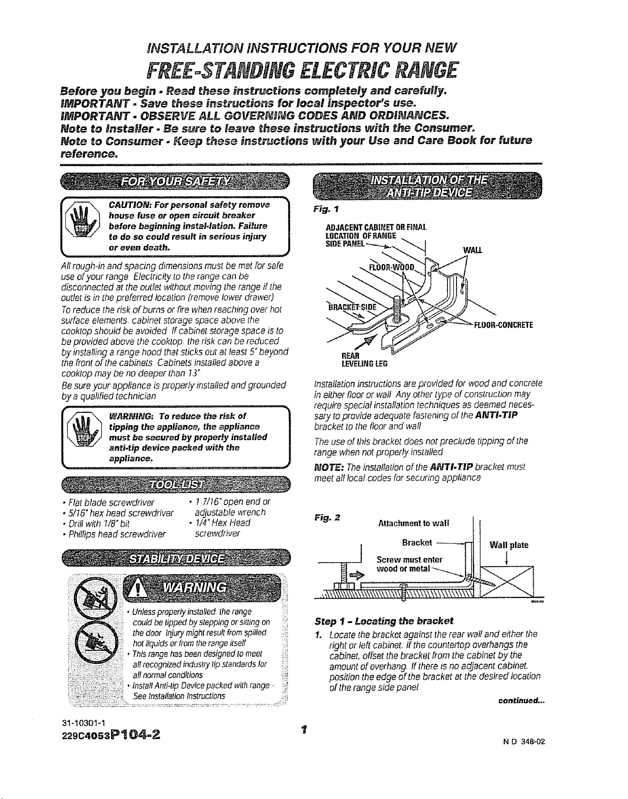
CAUTION: For personal safety remove
house fuse or open circuit breaker |
before beginning instaMation. Failure |
to do so could result in serious injury |
°re'e, de h.................. J
All rough-in and spacing dimensions must be met for safe
use ofyour range Electricity to the range can be
disconnected at the outlet without moving the range if the
outlet is in the preferred location (remove lower drawer)
Toreduce the risk of bums or fire when reaching over hot
surface elements, cabinet storage space above the
cooktop should be avoided If cabinet storage space is to
be provided above the cooktop, the risk can be reduced
by installing a range hood that sticks out at least 5" beyond
the front of the cabinets Cabinets installed above a
cooktop may"be no deeper than 73"
Be sure your appliance is properly installed and grounded
by a qualified technician
WARNING: To reduce the ri_k of
tipping the appliance, the appliance
must be secured byproperly iestafied
anti.tip device packed _Jith the
appliance,
• Flat blade screwdriver • I 7/15"open end OF
• 5/t6" hex head screwdriver adjustable wrench
• Drill with 7/8"bit • !/4" Hex Head
• Phillips head screwdriver screwdriver
• Unlessproperlyinstalled,therange ':
could be tipped bysteppingor sittingon ::
hot liquidsor fromtherangeitself
• Thisrangehasbeendesignedtomeet
all normalconditions
, fnstatfAnti-tip Devicepacked withrange.. [
.SeeInstallationInstructions
Fig. 1
ADJACENTCABINETORFINAL
LOCATIONOF_NGE
WAll
REAR
LEVELINGLEG
Installationinstructionsareprovided for woodand concrete
in eitherflooror wall Any othertype ofconstructionmay
requirespecial installationtechniquesas deemedneces-
sary toprovide adequatefasteningof theANTI.TIP
brackettothe floorand wall
Theuseofthis bracketdoesnotpreclude tipping of the
range whennotproperlyinstalled
NOTE: TheinstallationoftheANTI.TIP bracket must
meetall local codesfor securing appliance
Step 1 - Locating #_e bracket
1. Locate the bracket against the rear wall and either the
right or left cabinet. If the countertop overhangs the
cabinet, offset the bracket from the cabinet by the
amount of overhang, tf there is no adjacent cabinet.
position the edge of the bracket at the desired location
of the range side panel
continued...
31-10301-1
229C4o53P'! 04,,2 I
N D 348_02
2, Usethebracketas a templateand markthe4 required
holesasshownin Fig, I for thetype ofconstructionas
indicated in Step 2
Step 2. Anti.Tip bracket installation
Wood Construction
1, Floor: Locate thecenterof thetwo holesidentified in
Fig. 1asFLOOR-WOOD,Drilla 7/8"pifothole in the
centerof eachhole (a nailor awl maybe usedif a drill
isnotavailable),AND
2, Wall: Locatethetwo holesidentified in Fig, 1 as WALL°
Drillan angled t/8" pilot hole (asshownin Fig. 2) in the
centerof eachhole (anail or awlmay be used ifa drill
isnotavailable)
MounttheANTI-TIPbracket withthe4 screwsprovided as
illustratedinFig, 2
Concrete Construction
I. HardwareRequired: 4 each 1/4°x 7-7/2_Iag bolt
(notprovided) 4 each 1/2"0 D sleeveanchor
2. Drilltherecommendedsizehole forthe anchorsintothe
concreteat thecenterof theholesidentified asFLOOR-
CONCRETEand WALL. tnstaflthesleeveanchorinto
thedrilled holesand theninstallthe lag bolts through
thebracket Theboltsmustbe properly tightenedas
recommendedforthehardware
Step 3 - Checking the Installation
Io Completethe installationof therangeper theinstallation
instructionsprovided withtheproduct
2. CheckiftheANTI-TIPbracketis instafledand engaged
properly Removethekickpanel or storage drawerand
inspecttheREARLEVELINGLEG.Makesure itfits
securelyintotheslot
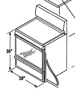
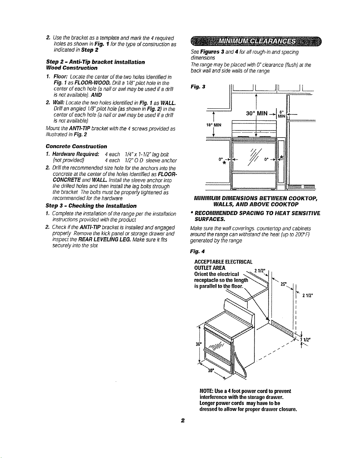
SeeFigures 3 and4 forallrough-inandspacing
dimensions
Therangemaybe placed withO"clearance(flush)atthe
back wallandside wallsoftherange
Fig. 3
T
18 = MIN
0 w .._
I[
i
i
WtlNIMUM DIMENSIONS BETWEEN COOKTOP,
WALLS, AND ABOVE COOKTOP
" RECOMMENDED SPACING TO HEAT SENSITIVE
SURFACES.
Makesurethewallcoverings, countertopand cabinets
aroundtherange can withstandtheheat (upto200_F)
generatedby therange
Fig. 4
ACCEPTABLEELECTRICAL
OUTLETAREA
Orienttheelectrical
receptaclesothe
isparalleltothefloor.
21f2"
NOTE:Usea 4foot powercordtoprevent
interferencewith the storagedrawer.
Longerpowercords mayhavetobe
dressedtoallow for properdrawerclosure,
REMOVINGPACKAGINGMATERIAL
Any packaging materials must be
removed during installation. This will
include adhesive tape, wire ties,
cardboard and protective plastic. Remove the
accessory pack from the oven. Failure to
remove these materials could result in
damage to the appliance once the appliance
has been turned on and surfaces have
heated.
This appliance must be supplied with the proper voltage
and frequency, and connected to an individual, properly
grounded branch circuit, protected by a circuit breaker or
time delay fuse. as noted on rating plate
Wiring must conform lo National Electrical Codes If the
electric service provided does not meet the above
specifications, call a licensed electrician
You can get a copy of the National Electrical Code, ANSt/
NFPA NO 70.Latest Edition by writing
National Fire Protection Association
Battery March Park
Quincy, MA 02269
Effective January t. 7996. the National Electrical Code
requires that new or rewired construction utilize a
4.conductor connection to an electric range When
installing an electric range in a new construction, follow
the instructions in NEW CONSTRUCTION AND FOUR-
CONDUC TOR BRANCH CIRCUlT CONNEC TION
tfyou fail to wireyour range in accordance with governing
codes, you may,create a hazardous condition
You must use a three,wire, single-phase AC 120/240 Voltor
208Y/120 Volt. 50 Hertz electrical system to operate your
range
Use//8 gauge wire and 40 Amp fuse or circuit breaker for
120/240 Voltand 208W120 Voltsystems
Therange connector block is approved for copper wire
connection only Ifyou are connecting to aluminum house
wiring, you must use special UL approved connectors for
joining copper to aluminum
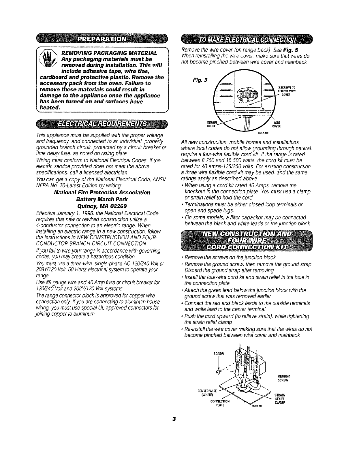
Removethe wirecover (onrange back) See Fig. 5
Whenreinstalling the wirecover, make surethat wires do
notbecome pinched between wire cover and mainback
5 i._" ,,°,_
CeVER
All newconstruction, mobile homes and installations
wherelocal codes do not allowgrounding throughneutral.
require a four-wireflexible cord kit ff the range israted
between&750 and !6.500 watts,the cord kit mustbe
rated for 40 amps-125/250volts Forexisting construction,
a threewireflexible cord kit may be used and thesame
ratings apply as described above
• Whenusing a cord kit rated 40 Amps. removethe
knockoutin theconnection plate Youmust usea clamp
or strain reliefto hold the cord
• Terminationsmustbe either closed loop terminalsor
open end spade tugs
• Onsome models,a filter capacitor may be connected
betweenthe black and whiteleads or thejunction block
, Remove the screws on thejunction block
, Remove the ground screw, then remove the ground strap
Oiscard the ground strap after removing
• Install the four-wire cord kit and strain relief in the hole in
the connection plate
• Attach thegreen lead below thejunction block with the
ground screw that was removed earlier
, Connect the red and black leads to the outside terminals
and white lead to the center terminal
, Push the cord upward (to relieve strain) while tightening
the strain relief clamp
• Re-install the wire cover making sure that the wires do not
become pinched between wire cover and mainback
3
•Removethescrews on thejunction block
•Installthethree.wirecord and thestrainreliefin thehole
in theconnectionplate
•Connectthered and black leadsto theouterIerminals
and thewhitelead to thecenter terminal
• Pushthecord upward (torelievestrain),whiletightening
thestrainreliefclamp
• Re-instaflthewirecover makingsure thatthewiresdo not
becomepinched betweenwirecover and mainback
If local codes
require an
ungrounded neutral:
• Removeground strap
• Fastenthe whitewire to
the centerterminal
• Usegrounding terminal
or lead toground unitin
accordance withlocal
codes,
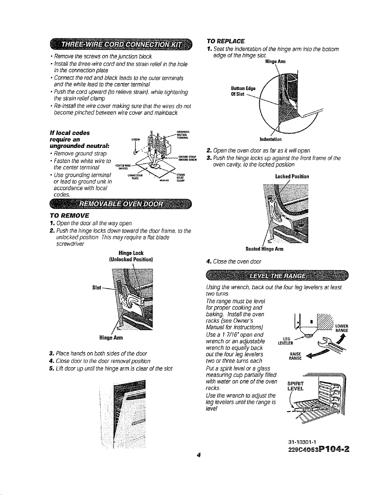
TO REPLACE
I. Seatthe indentationof thehingearminto thebottom
edge of thehinge slot,
HingeArm
BottomEdge
OfSlot
indentation
2. Openthe ovendoor asfar asit willopen
3, Pushthehinge locks up againstthe frontframe ofthe
oven cavity,tothelocked position
Locked Position
TO REMOVE
1. Open thedoor allthe wayopen
2. Pushthehinge locksdown towardthe door frame,to the
unlockedposition Thismayrequire a flat blade
screwdriver
HingeLock
(UnlockedPosition)
SeatedHingeAnn
4, Close the oven door
HingeArm
3. Placehands onboth sides of thedoor
4. Closedoor tothe doer removalposition
5oLift doorup untilthehinge armis clear oftheslot
Usingthe wrench,back out thefour leglevelers at least
two turns
Therange must be level
forproper cooking and
baking, Install theoven
racks (see Owner's
Manualfor instructions)
Usea 7 7/16"open end
wrench or an adjustable
wrench to equallyback
out thefour leg levelers
two or three turns each
Puta spirit levelor a glass
measuring cup partially filled
with water on one of theoven
racks
Use the wrench toad]]ustthe
leg levelers untilthe range is
level
SPIRIT
4
31-10301-1
22o_c40szP! 04=2

