Loading ...
Loading ...
Loading ...
9
WARNING: To reduce the risk of fire, electrical shock or personal injury, each quick connect
clip provided with this fan is designed to accept only one 12-gauge house wire and one lead wire
from the fan. If your house wire is larger than 12-gauge or there is more than one house wire to
connect to the corresponding fixture lead wires, consult an electrician.
CAUTION: Be sure outlet box is properly grounded and that a ground (green or bare) wire is present.
WARNING: The wires from the outlet box must be connected to a corresponding color of the
fan's wires. Be sure wire colors match before making connections. If house wires are different
colors than referred to in the following steps, stop immediately. A professional electrician is
recommended to determine wiring.
WIRING
WARNING: Using a full range dimmer switch (not included) to control fan speed will cause
a loud humming noise from fan. To reduce the risk of fire or electrical shock, do NOT use a full
range dimmer switch to control fan speed.
NOTE: To release a wire from clip (CC), twist
and pull the wire at the same time. This may
require some force.
1.
WARNING: Never connect ground wire to
white or black power supply wires.
CC
Clip x 6
Hardware Used
Make the necessary wiring connections for
remote control operation as detailed below and in
the figure. For each wire connection, use one of
the clips (CC).
CAUTION: Assistance from another person is
recommended for this step.
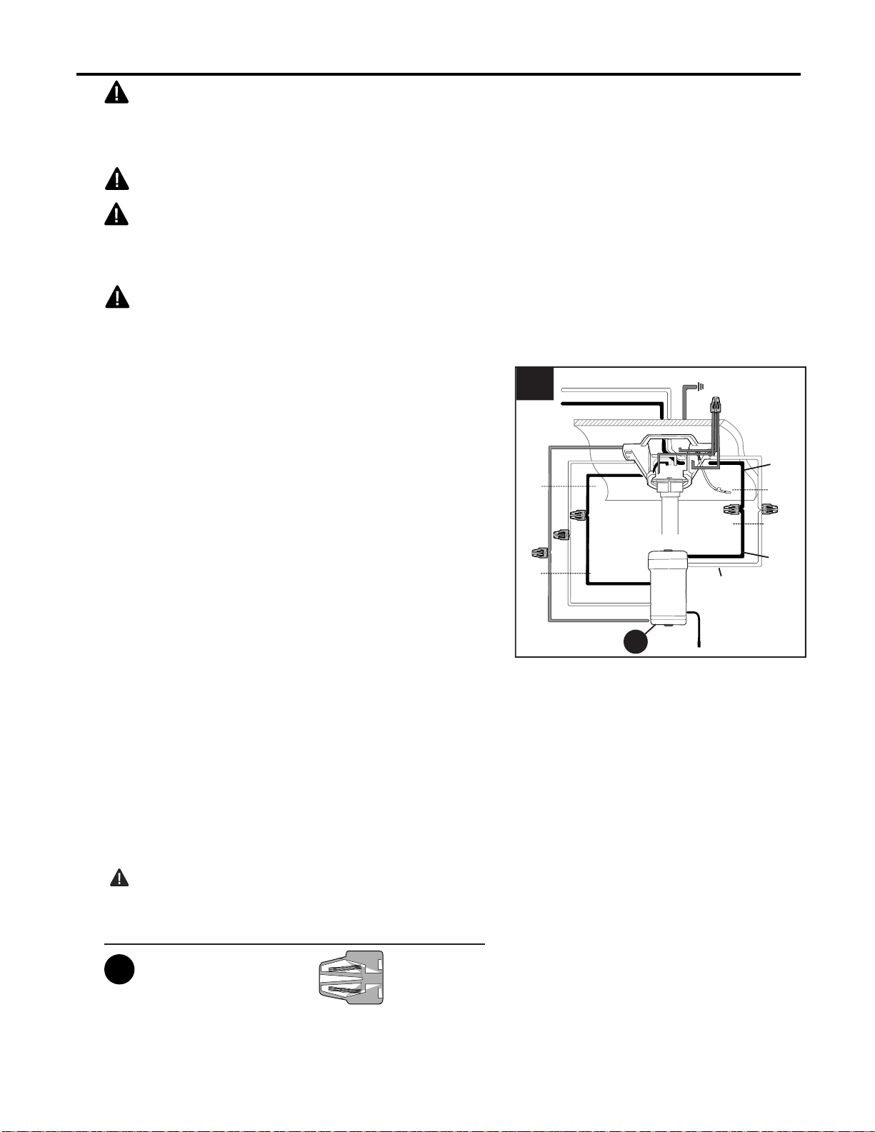
Connect all GROUND (GREEN) wires from fan
(on downrod (A), if applicable, and mounting
bracket (C)) to BARE/GREEN supply wire from
ceiling.
Connect BLACK wire (labeled AC IN L) from
remote control receiver (Y) to BLACK supply wire
from ceiling.
Connect WHITE wire (labeled AC IN N) from
remote control receiver (Y) to WHITE supply wire
from ceiling.
Connect WHITE wire (labeled TO MOTOR N)
from remote control receiver (Y) to WHITE wire
from motor housing (D).
Connect BLACK wire (labeled TO MOTOR L)
from remote control receiver (Y) to BLACK wire
from motor housing (D).
Connect BLUE wire (labeled FOR LIGHT) from
remote control receiver (Y) to BLUE wire from
motor housing (D).
Y
1
WHITE SUPPLY WIRE
BLACK SUPPLY WIRE
BLACK
BLACK
WHITE
BLUE
BLUE
WHITE
BLACK
AC IN L
WHITE
AC IN N
WHITE
GROUND (GREEN OR BARE)
GROUND
(GREEN OR BARE)
BLACK
FROM
RECEIVER
FROM
FAN
FROM
RECEIVER
FROM
CEILING
NOTE: Pull on each wire to make sure wires
are secure in the clip (CC).
Loading ...
Loading ...
Loading ...