Loading ...
Loading ...
Loading ...
920-087-02 (9-03)
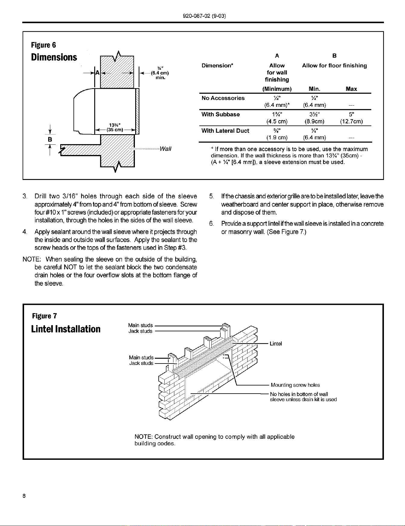
Figure 6
Dimensions
A
S
_ ...........Wall
'_7€/////_ _ 6.4 cm
in.
13¾ _
Dimension*
A B
Allow Allow for floor finishing
for wall
finishing
(Minimum) Min. Max
No Accessories ¼" ¼"
(6.4 ram)* (6.4 mm) ---
With Subbase 1¾" 3½" 5"
(4.5 cm) (8.9cm) (12.7cm)
With Lateral Duct ¾" ¼"
(1.9 cm) (6.4 mm) ---
* If mere than one accessory [sto be used, use the maximum
dimension. Ifthe wail thickness is more than 13¾" (35cm) -
(A + ¼" [6.4 mm]), a sleeve extension must be used.
,
Drill two 3/16" holes through each side of the sleeve
approximately4" from top and4" from bottom of sleeve. Screw
four #10x 1"screws (included)or appropriatefastenersfor your
installation, through the holes inthe sides of the wall sleeve.
4. Apply sealant around the wall sleevewhere itprojects through
the insideand outside wall surfaces. Apply the sealant to the
screw heads or the tops of the fasteners used in Step #3.
NOTE: When sealing the sleeve on the outside of the building,
be careful NOT to let the sealant block the two condensate
drain holes or the four overflow slots at the bottom flange of
the sleeve.
5. Ifthe chassisandexteriorgrilleareto beinstanedlater,leavethe
weatherboard and center support in place, otherwise remove
and dispose of them.
6. Providea supportlintelifthewall sleeve isinstalledina concrete
or masonry wall. (See Figure 7.)
Rgure 7
Main studs
LintelInstallation Jack studs
Jack stud
Untel
Mounting screw holes
No holes in bottom of wall
sleeve unless drain kit is used
NOTE: Construct wall opening to comply with all applicable
building codes.
8
Loading ...
Loading ...
Loading ...