Loading ...
Loading ...
Loading ...
6
Application Guide
Application Overview
This section of the manual shows the various ways in which the AFS2 can be integrated into a system. It provides system
diagrams and notes for each application type. Use these diagrams and notes for reference when initially connecting and
configuring the AFS2 for your application.
The four basic ways to hookup the AFS2 to your system are as follows:
1� Connected to the mixer’s channel insert jacks.
2� Connected to the mixer’s subgroup (bus) insert jacks.
3� Connected to the mixer’s master insert jacks.
4� Connected inline between the mixer and amp (or between the mixer and active crossover if using one).
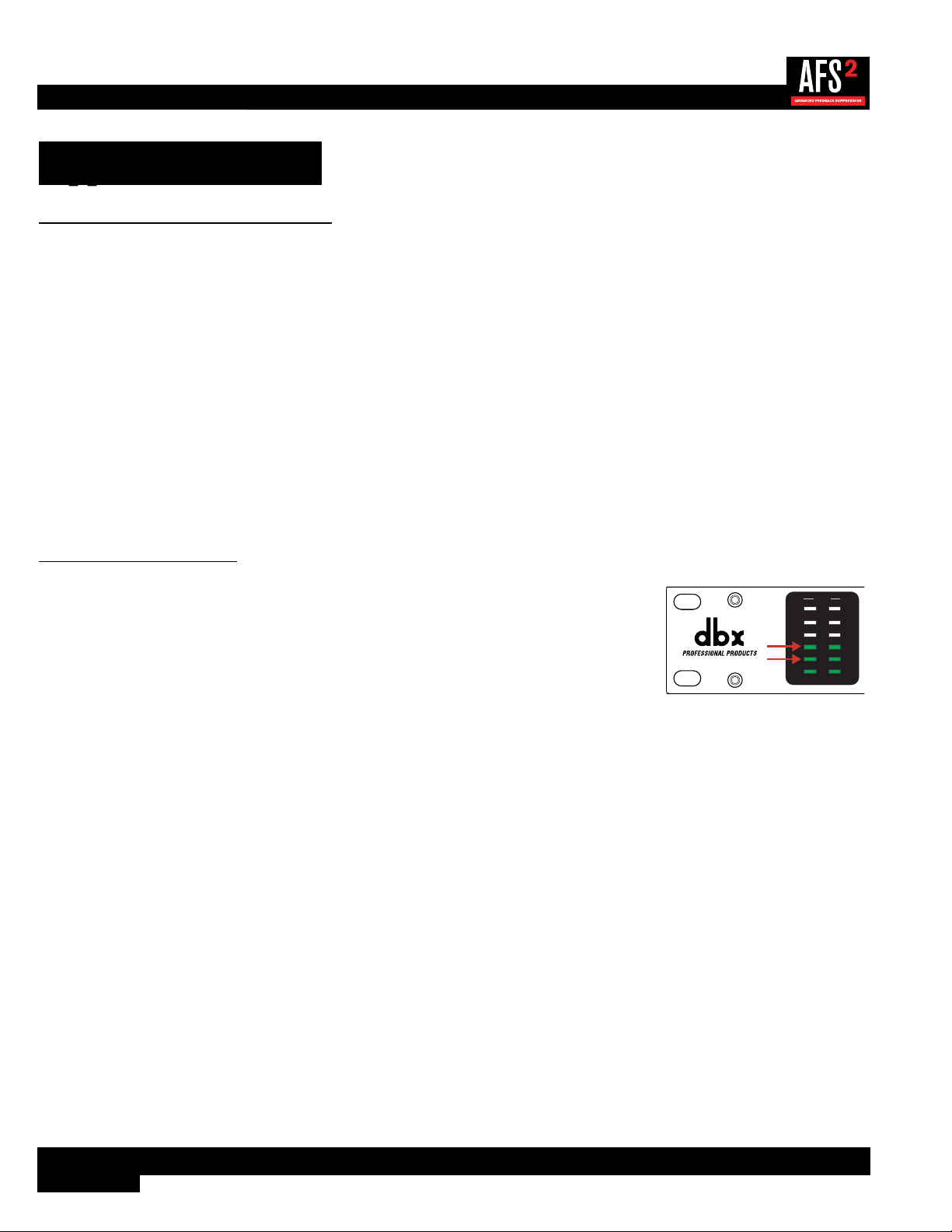
Gain Structure
For maximum performance and proper operation, the average input signal level to the AFS2
should consistently light the ‘20’ LED, with the ‘10’ LED occasionally lighting. Connection
methods 1, 2, and 3 above are the preferred way to connect the AFS2 since the insert points
on most mixers are pre fader. This allows proper signal level to be fed to the AFS2 without the
channel, subgroup, or master fader affecting the level. Be sure to check the mixer’s manual for
the nominal operating level of the insert jacks and then set the +4 dBu/-10 dBV switch on the
back of the AFS2 accordingly.
20
10
CLIP
3
0
SIG
CH 1
CH 2
INPUT
If no insert points are available, then method 4 would be utilized. In this situation, be sure that the AFS2 input level allows
the ‘20’ and ‘10’ LEDs to light as indicated above. If optimal level cannot be achieved, you can try raising the SENSITIVITY
parameter. See ‘AFS Options Menu’ on page 24 for more information on the SENSITIVITY parameter.
Loading ...
Loading ...
Loading ...