Loading ...
Loading ...
Loading ...
8
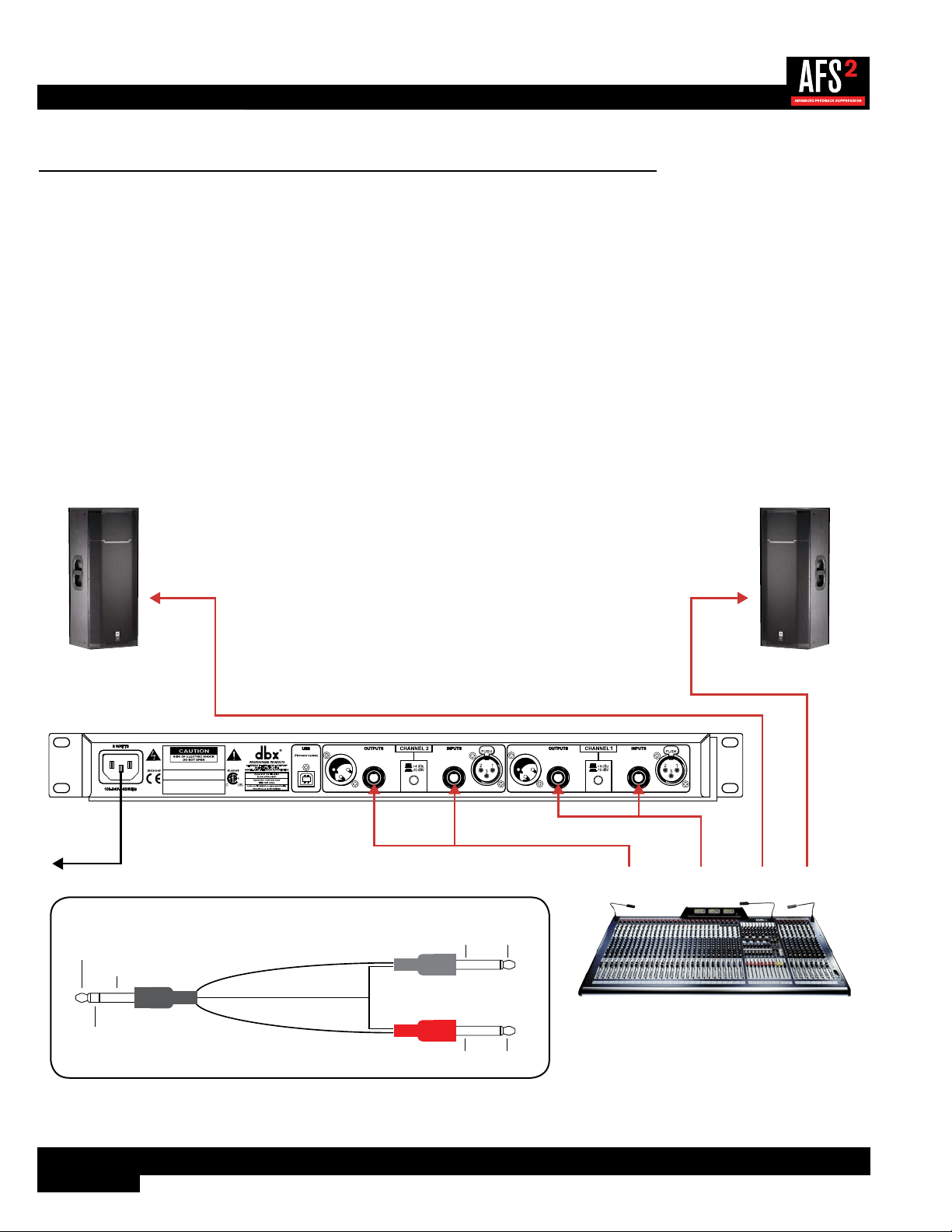
Application 2 – Mixer Subgroup (Bus) Inserts
Use this configuration to protect two independent groups of microphones from feedback while leaving all other audio channels
unaffected. For example, feedback suppression could be applied to certain instruments which require feedback suppression
(e.g., drum mics, vocal mics, etc.) while keeping instruments that desire feedback (such as loud guitar cabinets in a rock band)
separated. This application provides two channels of feedback suppression with up to 24 filters per microphone channel.
Application Notes:
• Ensure all interconnecting equipment is turned off, including the amplifiers or powered speakers.
• Connect the mixer’s subgroup inserts to the AFS2.
• Apply power to the system. Ensure that the amplifiers or powered speakers are turned on last.
• Ensure the AFS2 is configured for dual mono (unlinked) operation if processing two independent subgroups. If processing
a stereo subgroup, the AFS2 should be configured for stereo (linked) operation. See ‘Linking/Unlinking Channels’ on
page 18 for further information on this configuration option.
Left Main
Powered Speaker
Right Main
Powered Speaker
Mixer
WIZARD
20
10
CLIP
3
0
SIG
CH 1
CH 2
INPUT FILTERS
1 2 3 4 5 6 7 8 9 10 11 12 13 14 15 16 17 18 19 20 21 22 23 24
CH 1
CH 2
BYPASS
SELECT
MENU / BACK
AFS WIZARD
Configure Channel 2
Configure as Stereo
Configure Channel 1
A HARMAN INTERNATIONAL COMPANY
SALT LAKE CITY, UTAH
MODEL: AFS2 FEEDBACK SUPPRESSION
WARNING:
TO REDUCE THE RISK OF FIRE
OR ELECTRIC SHOCK DO NOT EXPOSE THIS
EQUIPMENT TO RAIN OR MOISTURE
ATTENTION:
POUR RÉDUIRE LE RISQUE
D'INCENDIE OU D'ÉLECTROCUTION
N'EXPOSEZ PAS CET APPAREIL À LA PLUIE
OU L'HUMIDITÉ
ELECTRIQUE - NE PAS OUVRIR
RISQUE DE CHOC
ATTENTION:
Subgroup 1
Insert
Subgroup 2
Insert
L Main
Out
R Main
Out
Insert Cable
Insert Cable
SendReturn
SendReturn
To Power
Outlet
Insert Cable Diagram
Tip + (Send)
Ring + (Return)
Ground -
Ground -
Tip +
Ring +
To Input
To Mixer Insert
Tip / Send
Ring / Return
To Output
Ground - Tip +
Ring +Ground -
Loading ...
Loading ...
Loading ...