Owner’s Manual

Warranty
1. The warranty registration card that accompanies this product must be mailed within 30 days after purchase date to validate
this warranty. You can also register online at www.dbxpro.com. Proof-of-purchase is considered to be the responsibility of the
consumer. A copy of the original purchase receipt must be provided for any warranty service.
2. dbx warrants this product, when purchased new from an authorized U.S. dbx dealer and used solely within the U.S., to be
free from defects in materials and workmanship under normal use and service. This warranty is valid to the original purchaser
only and is non-transferable.
3. dbx liability under this warranty is limited to repairing or, at our discretion, replacing defective materials that show evidence
of defect, provided the product is returned to dbx WITH RETURN AUTHORIZATION from the factory, where all parts and labor
will be covered up to a period of two years. A Return Authorization Number must first be obtained from dbx. The company shall
not be liable for any consequential damage as a result of the product’s use in any circuit or assembly.
4. dbx reserves the right to make changes in design or make additions to or improvements upon this product without incurring
any obligation to install the same additions or improvements on products previously manufactured.
5. The foregoing is in lieu of all other warranties, expressed or implied, and dbx neither assumes nor authorizes any person to
assume on its behalf any obligation or liability in connection with the sale of this product. In no event shall dbx or its dealers be
liable for special or consequential damages or from any delay in the performance of this warranty due to causes beyond their
control.
Technical Support & Service
If you require technical support, contact dbx Technical Support. Be prepared to accurately describe the problem. Know the
serial number of your device – this is printed on a sticker attached to the chassis. If you have not already taken the time to fill
out your warranty registration card and send it in, please do so now. You may also register online at www.dbxpro.com.
Before you return a product to the factory for service, we recommend you refer to this manual. Make sure you have correctly
followed installation steps and operating procedures. For further technical assistance or service, please contact our Technical
Support Department at (801) 566-8800 or visit www.dbxpro.com. If you need to return a product to the factory for service, you
MUST first contact our Technical Support Department to obtain a Return Authorization Number.
NO RETURNED PRODUCTS WILL BE ACCEPTED AT THE FACTORY WITHOUT A RETURN AUTHORIZATION NUMBER.
Please refer to the Warranty information, which extends to the first end-user. After expiration of the warranty, a reasonable
charge will be made for parts, labor, and packing if you choose to use the factory service facility. In all cases, you are
responsible for transportation charges to the factory. If the product is still under warranty, dbx will pay the return shipping.
Use the original packing material if it is available. Mark the package with the name of the shipper and with these words in red:
DELICATE INSTRUMENT, FRAGILE! Insure the package properly. Ship prepaid, not collect. Do not ship parcel post.

1
Table of Contents
Overview ����������������������������������������������������������������������� 2
Introduction ������������������������������������������������������������������������������������������������� 2
Features ������������������������������������������������������������������������������������������������������� 3
The AFS Advantage ��������������������������������������������������������������������������������� 3
Installation ������������������������������������������������������������������� 4
Installation Recommendations ��������������������������������������������������������������� 4
Making Connections �������������������������������������������������������������������������������� 4
Applying Power ����������������������������������������������������������������������������������������� 5
Application Guide ������������������������������������������������������� 6
Application Overview ������������������������������������������������������������������������������� 6
Gain Structure ������������������������������������������������������������������������������������������� 6
Application 1 – Mixer Channel Inserts ������������������������������������������������ 7
Application 2 – Mixer Subgroup (Bus) Inserts���������������������������������� 8
Application 3 – Mixer Master Inserts ��������������������������������������������������� 9
Application 4 – In-line Between Mixer & Amp���������������������������������10
The User Interface & Connectors �������������������������11
Front Panel �����������������������������������������������������������������������������������������������11
Rear Panel ������������������������������������������������������������������������������������������������13
Operating The AFS2 ������������������������������������������������14
Navigating & Modes Of Operation ����������������������������������������������������� 14
Home Mode ��������������������������������������������������������������������������������������� 14
Menu Mode����������������������������������������������������������������������������������������14
Wizard Mode ������������������������������������������������������������������������������������� 15
Menu Navigation Map ���������������������������������������������������������������������15
The AFS Filters ����������������������������������������������������������������������������������������16
Fixed Filters ���������������������������������������������������������������������������������������� 16
Live Filters ������������������������������������������������������������������������������������������16
Filter Widths ��������������������������������������������������������������������������������������16
Clearing Filters ����������������������������������������������������������������������������������17
Linking/Unlinking Channels ������������������������������������������������������������������ 18
Ringing Out The Sound System ���������������������������������������������������������19
Using The Wizard �����������������������������������������������������������������������������19
Manual Method ���������������������������������������������������������������������������������19
Presets ������������������������������������������������������������������������������������������������������� 21
Saving Presets ����������������������������������������������������������������������������������21
Loading Presets �������������������������������������������������������������������������������21
Front Panel Lockout �������������������������������������������������������������������������������22
Factory Resets ����������������������������������������������������������������������������������������� 23
Factory Default Reset ���������������������������������������������������������������������23
Factory Hard Reset �������������������������������������������������������������������������23
The Menus & Parameters ��������������������������������������� 24
AFS Options Menu ��������������������������������������������������������������������������������24
Preset Menu ���������������������������������������������������������������������������������������������27
System Menu �������������������������������������������������������������������������������������������27
Technical Information ���������������������������������������������� 28
Audio Cable Diagrams ��������������������������������������������������������������������������28
Dimensions �����������������������������������������������������������������������������������������������29
Specifications ������������������������������������������������������������������������������������������30

2
Overview
Introduction
The AFS2 is the second generation feedback suppression processor from dbx
®
. Whether you’re playing with your band, a live
sound engineer, or an audio installer, you know how annoying and offensive feedback can be. Feedback is caused when an
in-phase audio loop is created between an input transducer (such as a guitar pickup or microphone) and an output transducer
(a loudspeaker). Using the updated AFS algorithm first introduced in the acclaimed dbx DriveRack PA2 speaker management
system processor, the AFS2 kills feedback dead in its tracks without adversely affecting the tone of your system.
The AFS2 is a two-channel device and can be configured for stereo linked or dual mono operation. It provides 24 filters per
channel with filter widths as narrow as 1/80th of an octave. Filters can be configured for Live or Fixed operation. Use the
Fixed filters to initially ring out the system for higher gain before feedback then use the Live filters for on-the-fly, automatic
feedback protection during the performance as conditions change. 24 Filter LEDs show at-a-glance status of all filters so
you’re never left guessing what the processor is doing. Need more detailed information about the filters? The easy-to-read,
backlit LCD display shows the frequency, width, and attenuation amount of each set filter.
Not sure how to ring out a sound system? No problem. The new Wizard in the AFS2 walks you through the entire setup
and ring-out procedure. Feedback suppression couldn’t be any easier. Just press the big, red Wizard button and follow the
on-screen instructions.
The updated AFS algorithm in the AFS2 can now detect and eliminate feedback faster than ever before and with even higher
precision. The AFS2 offers the following enhancements over the AFS224:
• It’s faster at eliminating the offending feedback frequency.
• It can better determine what is actually feedback, making it far less likely to set false triggers on feedback-like audio
sources such as a flute or keyboard.
• It can better determine how much attenuation is required to notch out the feedback, resulting in notch filters which aren’t as
deep and are even less audible.
• It prevents the filters from being too narrow to tackle feedback at lower frequencies.
• It has better frequency resolution which provides pinpoint accuracy and uses the narrowest filters possible.
• Live filters are lifted more gradually to better determine if it is safe to lift the filter, preventing blaring feedback from
suddenly returning.
• Allows you to store up to 5 user presets.
We think you’ll agree that the AFS2 couldn’t be any easier to use and is up for any feedback suppression task you throw at it.
Thanks for choosing dbx.
3
Features
• Latest dbx Advanced Feedback Suppression (AFS™) Technology
• 24-Bit A/D, D/A Converters
• 48kHz/24-Bit Internal Processing
• 24 Programmable Filters w/Status LEDs per Channel
• Stereo Linked or Dual Mono Operation
• Live & Fixed Filter Modes
• Selectable Live Filter Lift Times
• Application-Specific Filter Types Include: Speech, Music, Music/Speech
• 5 User Storable Presets
• Input Signal Level Metering w/Input Clip Indicators
• XLR and TRS Electronically Balanced Input and Outputs
• +4 dBu / -10 dBV Operating Level Switch per Channel
• USB Port for Firmware Updates
The AFS Advantage
Key features that set AFS apart are the Fixed and Live Modes of operation and the Live Filter Lift feature. The Live Mode
of operation continuously updates filter placement which provides flexibility during a performance. The Live Filter Lift feature
automatically removes filter assignments that are no longer necessary, which in turn, maximizes sonic integrity.
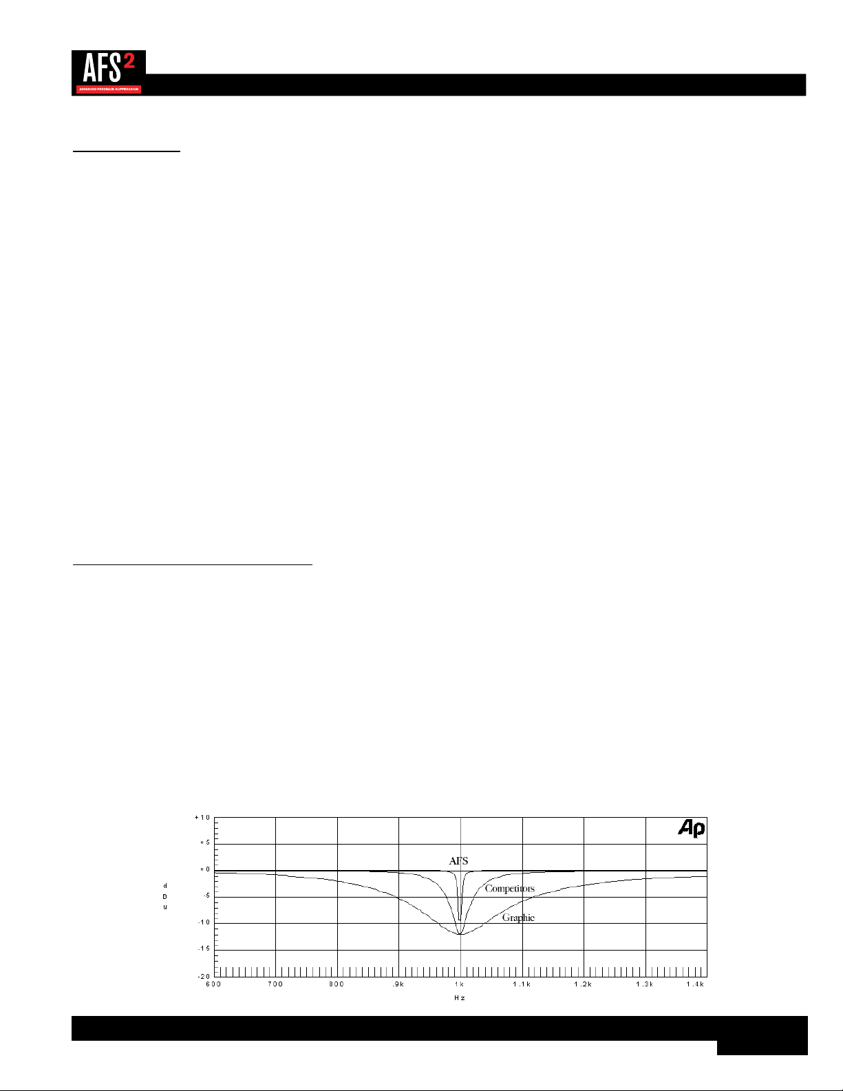
AFS uses precision frequency detection and state-of-the-art processing to determine the exact range of feedback frequencies
to remove (instead of indiscriminately removing large sections of audio). In the past, graphic equalizers were used to eliminate
feedback from a system. This was an acceptable method for eliminating feedback, but when this method is put up against
precision notch filters, such as those found in AFS, it becomes very evident that using graphic equalizers for this task severely
affects the tone of the system. With AFS, the precision filters remove only a fraction of the frequency spectrum, eliminating
the feedback with far less audible artifacts. The below graph shows a comparison of filter widths between the AFS filters,
conventional 1/3 octave EQ filters, and notch filters used in competitor’s feedback elimination processors.
Filter Precision Comparison Chart

4
Installation
Installation Recommendations
FOR RACK MOUNT USE ONLY. Install the AFS2 in a standard-width rack with the provided rack screws. The AFS2 should
not be mounted above or below anything that generates excessive heat. Ambient temperatures should not exceed 95ºF (35ºC)
when equipment is in use. Although the unit is shielded against radio frequency and electromagnetic interference, extremely
high fields of RF and EMI should be avoided where possible.
Making Connections
The AFS2 has balanced inputs and outputs that can be connected to any balanced or unbalanced line-level device. To connect
the AFS2 to your sound system:
1� Ensure the power is turned off on all interconnecting equipment and the AFS2 before making audio connections.
2� See ‘Application Guide’ on page 6 for application system diagrams and notes which can be used for reference
when connecting the AFS2 to your system.
3� Make audio connections via the XLR or 1/4" TRS connectors according to application needs (see ‘Audio Cable
Diagrams’ on page 28 for information on cable wiring). Either the XLR or 1/4" input and output connectors
can be used for balanced or unbalanced connections. However, making simultaneous connections to both inputs of a
channel could unbalance balanced lines, cause phase cancellation, short a conductor to ground, or cause damage to
other equipment connected to the AFS2, therefore, it is not recommended. Connecting to both outputs of a channel
simultaneously is perfectly acceptable as long as the combined parallel load is 1.2kΩ or greater. This is typically not a
problem since most modern-day audio devices have been designed with high-impedance line inputs. If desired, parallel
resistance calculators can be found online and used to verify if the parallel load meets this criteria. Simply enter the input
impedance for the two receiving devices into the calculator to calculate the combined parallel load. Note that connecting
both XLR and 1/4˝ outputs of a channel to an unbalanced and balanced input simultaneously will cause the balanced line
to become unbalanced.
NOTE: The +4 dBu/-10 dBV switch on the back panel of the AFS2 must be set to the correct position for your
application in order to avoid performance issues. +4 dBu is referred to as ‘pro level’ and will be the correct setting for most
applications, as most pro and semi-pro mixers will output a nominal level of around +4 dBu. -10 dBV is referred to as
‘consumer level’ and will need to be used when connecting a source which has an output level approximately 12 dB lower
than pro level equipment. If you’re unsure of the nominal operating level of your mixer’s connections, take a look at the
mixer’s manual or contact the mixer manufacturer.

5
Applying Power
1� Ensure your power amplifiers or powered speakers are turned off.
2� Make sure that the included IEC power cable provided with your AFS2 has the proper connector for connection to your
AC power outlet.
3� Connect the power cable to the AC power inlet on the AFS2’s back panel.
4� Route the AC power cord to a convenient power outlet away from audio lines. Since the AFS2 does not have a power
switch, an AC power strip or power conditioner can be used for switching power to the AFS2 on and off. Since the AFS2
consumes a relatively small amount of power, the unit may be left on continuously if required for the application.
5� Apply power to your mixer and rack processors then your power amplifiers or powered speakers. Note that the AFS2 will
mute its outputs as it powers up and initializes. Once initialized, the outputs will automatically unmute.
WARNING: When powering up a fully connected PA system, it is advisable to ALWAYS turn on the mixer and rack
equipment (including the AFS2) first then turn on your amplifiers or powered speakers. It’s also a good idea to ensure
you’re not passing audio to the mixer’s outputs (or ensure your mixer’s master faders are all the way down) before applying
power to the amplifiers. When powering down the system, you should ALWAYS power down the amplifiers first, wait about
10 seconds to allow them to discharge, then power down the mixer and rack mount equipment. In short, every time you use
your system, the power amps should be the last components turned on and the first components turned off.
6
Application Guide
Application Overview
This section of the manual shows the various ways in which the AFS2 can be integrated into a system. It provides system
diagrams and notes for each application type. Use these diagrams and notes for reference when initially connecting and
configuring the AFS2 for your application.
The four basic ways to hookup the AFS2 to your system are as follows:
1� Connected to the mixer’s channel insert jacks.
2� Connected to the mixer’s subgroup (bus) insert jacks.
3� Connected to the mixer’s master insert jacks.
4� Connected inline between the mixer and amp (or between the mixer and active crossover if using one).
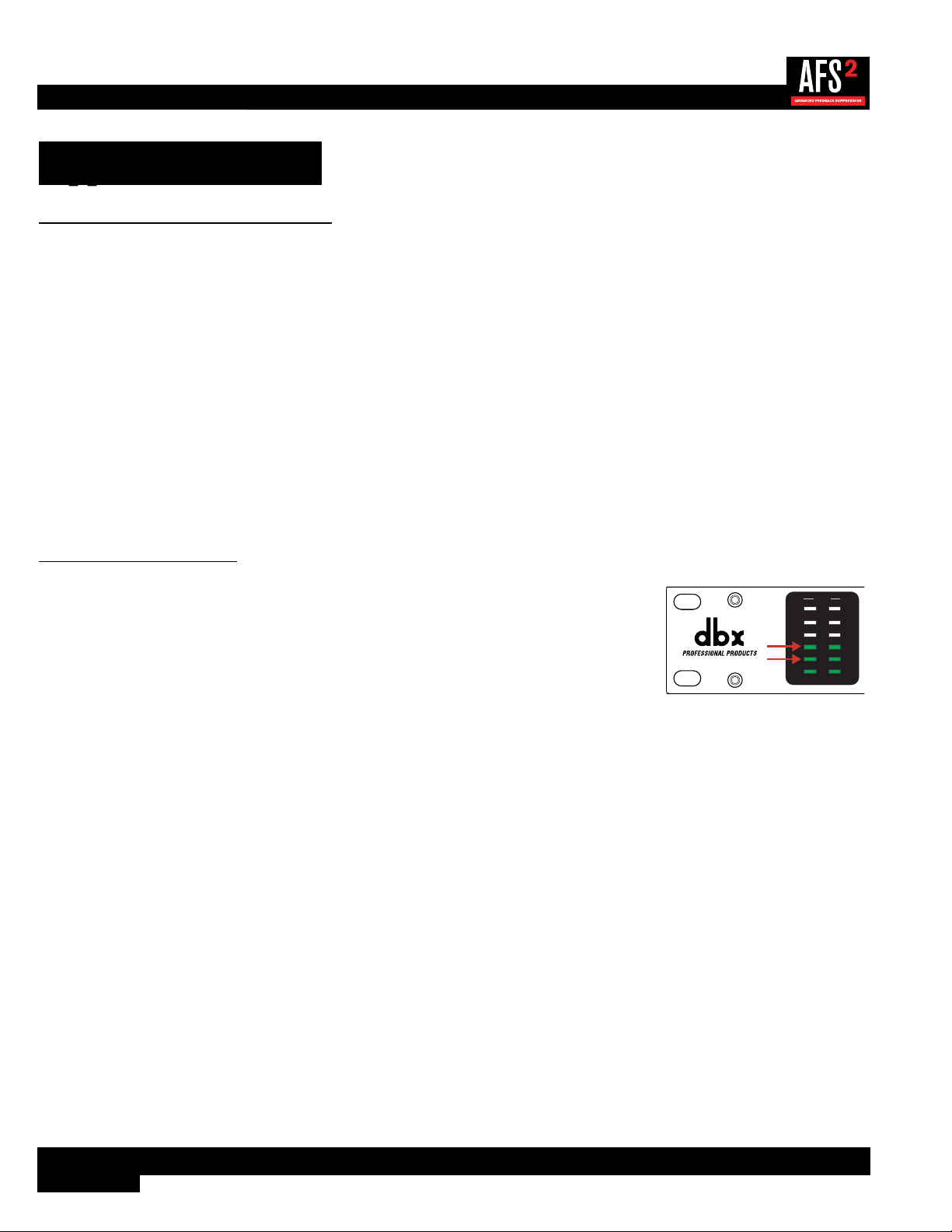
Gain Structure
For maximum performance and proper operation, the average input signal level to the AFS2
should consistently light the ‘20’ LED, with the ‘10’ LED occasionally lighting. Connection
methods 1, 2, and 3 above are the preferred way to connect the AFS2 since the insert points
on most mixers are pre fader. This allows proper signal level to be fed to the AFS2 without the
channel, subgroup, or master fader affecting the level. Be sure to check the mixer’s manual for
the nominal operating level of the insert jacks and then set the +4 dBu/-10 dBV switch on the
back of the AFS2 accordingly.
20
10
CLIP
3
0
SIG
CH 1
CH 2
INPUT
If no insert points are available, then method 4 would be utilized. In this situation, be sure that the AFS2 input level allows
the ‘20’ and ‘10’ LEDs to light as indicated above. If optimal level cannot be achieved, you can try raising the SENSITIVITY
parameter. See ‘AFS Options Menu’ on page 24 for more information on the SENSITIVITY parameter.
7
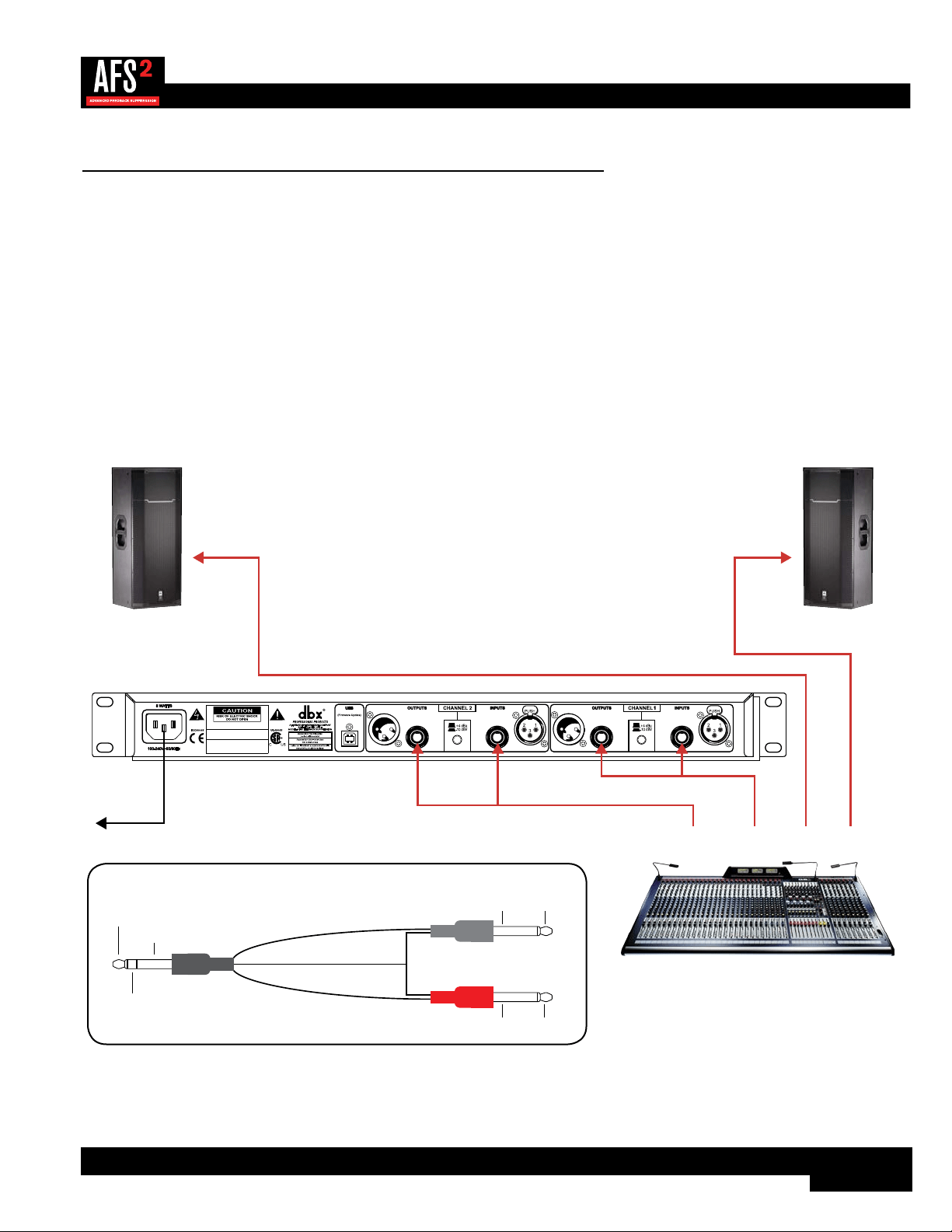
Application 1 – Mixer Channel Inserts
Use this configuration to independently protect two single microphones from feedback while leaving all other audio channels
unaffected. This application provides two independent channels of feedback suppression with up to 24 filters per microphone
channel.
Application Notes:
• Ensure all interconnecting equipment is turned off, including the amplifiers or powered speakers.
• Connect the mixer’s channel inserts to the AFS2.
• Apply power to the system. Ensure that the amplifiers or powered speakers are turned on last.
• Ensure the AFS2 is configured for dual mono (unlinked) operation, see ‘Linking/Unlinking Channels’ on page 18
for further information.
Left Main
Powered Speaker
Right Main
Powered Speaker
Mixer
WIZARD
20
10
CLIP
3
0
SIG
CH 1
CH 2
INPUT FILTERS
1 2 3 4 5 6 7 8 9 10 11 12 13 14 15 16 17 18 19 20 21 22 23 24
CH 1
CH 2
BYPASS
SELECT
MENU / BACK
AFS WIZARD
Configure Channel 2
Configure as Stereo
Configure Channel 1
A HARMAN INTERNATIONAL COMPANY
SALT LAKE CITY, UTAH
MODEL: AFS2 FEEDBACK SUPPRESSION
WARNING:
TO REDUCE THE RISK OF FIRE
OR ELECTRIC SHOCK DO NOT EXPOSE THIS
EQUIPMENT TO RAIN OR MOISTURE
ATTENTION:
POUR RÉDUIRE LE RISQUE
D'INCENDIE OU D'ÉLECTROCUTION
N'EXPOSEZ PAS CET APPAREIL À LA PLUIE
OU L'HUMIDITÉ
ELECTRIQUE - NE PAS OUVRIR
RISQUE DE CHOC
ATTENTION:
Ch. 1
Insert
Ch. 2
Insert
L Main
Out
R Main
Out
To Power
Outlet
Insert Cable
Insert Cable
SendReturn
SendReturn
Insert Cable Diagram
Tip + (Send)
Ring + (Return)
Ground -
Ground -
Tip +
Ring +
To Input
To Mixer Insert
Tip / Send
Ring / Return
To Output
Ground - Tip +
Ring +Ground -
8
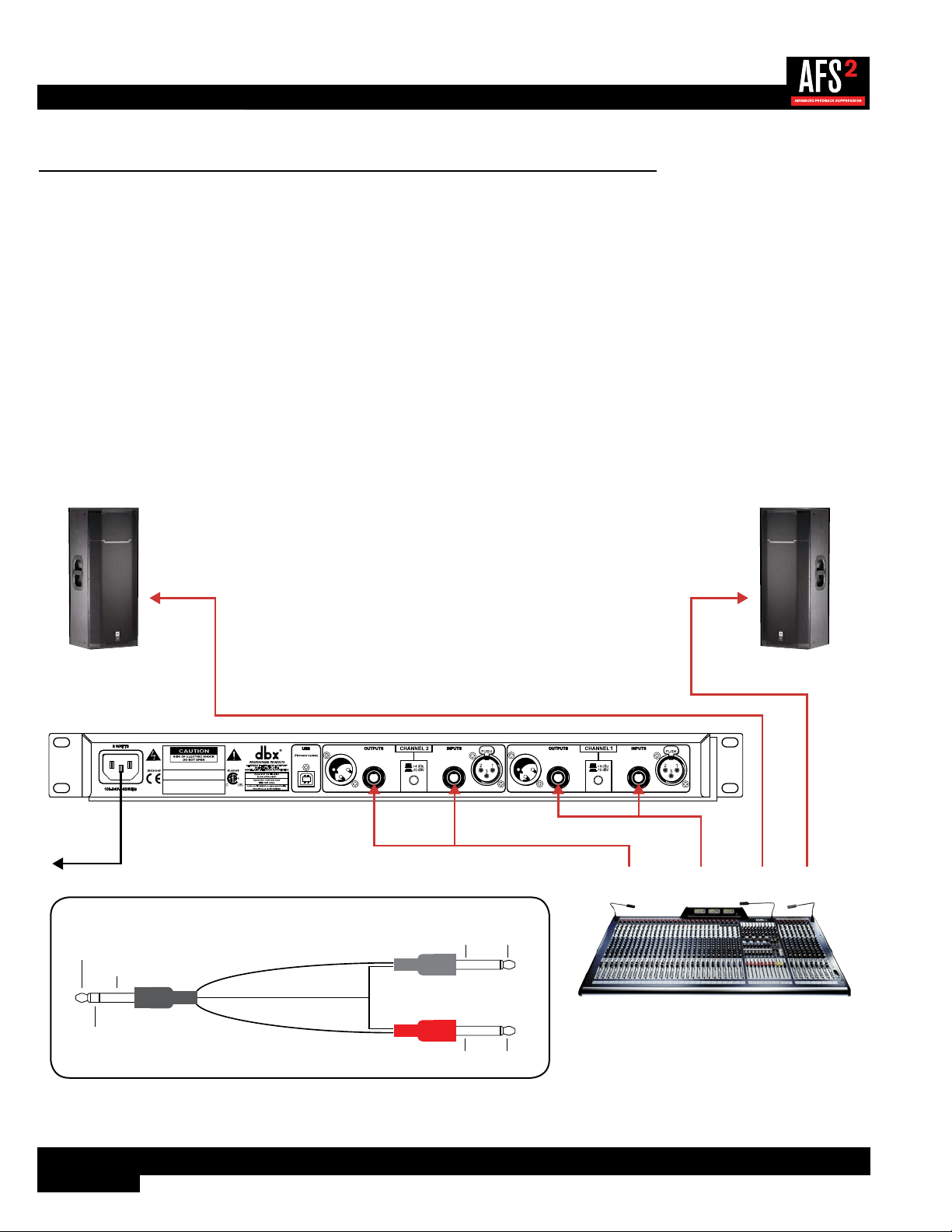
Application 2 – Mixer Subgroup (Bus) Inserts
Use this configuration to protect two independent groups of microphones from feedback while leaving all other audio channels
unaffected. For example, feedback suppression could be applied to certain instruments which require feedback suppression
(e.g., drum mics, vocal mics, etc.) while keeping instruments that desire feedback (such as loud guitar cabinets in a rock band)
separated. This application provides two channels of feedback suppression with up to 24 filters per microphone channel.
Application Notes:
• Ensure all interconnecting equipment is turned off, including the amplifiers or powered speakers.
• Connect the mixer’s subgroup inserts to the AFS2.
• Apply power to the system. Ensure that the amplifiers or powered speakers are turned on last.
• Ensure the AFS2 is configured for dual mono (unlinked) operation if processing two independent subgroups. If processing
a stereo subgroup, the AFS2 should be configured for stereo (linked) operation. See ‘Linking/Unlinking Channels’ on
page 18 for further information on this configuration option.
Left Main
Powered Speaker
Right Main
Powered Speaker
Mixer
WIZARD
20
10
CLIP
3
0
SIG
CH 1
CH 2
INPUT FILTERS
1 2 3 4 5 6 7 8 9 10 11 12 13 14 15 16 17 18 19 20 21 22 23 24
CH 1
CH 2
BYPASS
SELECT
MENU / BACK
AFS WIZARD
Configure Channel 2
Configure as Stereo
Configure Channel 1
A HARMAN INTERNATIONAL COMPANY
SALT LAKE CITY, UTAH
MODEL: AFS2 FEEDBACK SUPPRESSION
WARNING:
TO REDUCE THE RISK OF FIRE
OR ELECTRIC SHOCK DO NOT EXPOSE THIS
EQUIPMENT TO RAIN OR MOISTURE
ATTENTION:
POUR RÉDUIRE LE RISQUE
D'INCENDIE OU D'ÉLECTROCUTION
N'EXPOSEZ PAS CET APPAREIL À LA PLUIE
OU L'HUMIDITÉ
ELECTRIQUE - NE PAS OUVRIR
RISQUE DE CHOC
ATTENTION:
Subgroup 1
Insert
Subgroup 2
Insert
L Main
Out
R Main
Out
Insert Cable
Insert Cable
SendReturn
SendReturn
To Power
Outlet
Insert Cable Diagram
Tip + (Send)
Ring + (Return)
Ground -
Ground -
Tip +
Ring +
To Input
To Mixer Insert
Tip / Send
Ring / Return
To Output
Ground - Tip +
Ring +Ground -
9
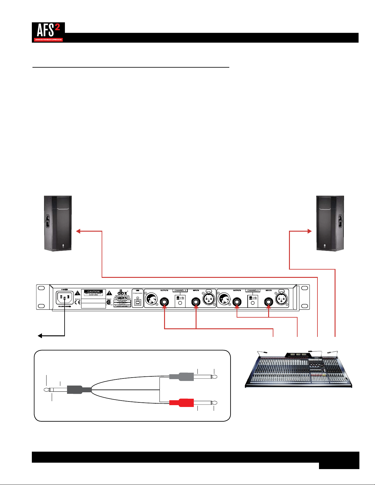
Application 3 – Mixer Master Inserts
Use this configuration to protect the entire system from feedback. Your mixer must have master insert connections to use this
configuration. This places the AFS2 before the master fader so that it can work optimally no matter where the master fader is
set. If you have a system EQ, you can place it before or after the AFS2 in the chain. This application provides two channels of
feedback suppression with up to 24 filters per channel.
Application Notes:
• Ensure all interconnecting equipment is turned off, including the amplifiers or powered speakers.
• Connect the mixer’s master inserts to the AFS2.
• Apply power to the system. Ensure that the amplifiers or powered speakers are turned on last.
• Ensure the AFS2 is configured for stereo (linked) operation, see ‘Linking/Unlinking Channels’ on page 18 for
further information.
Left Main
Powered Speaker
Right Main
Powered Speaker
Mixer
WIZARD
20
10
CLIP
3
0
SIG
CH 1
CH 2
INPUT FILTERS
1 2 3 4 5 6 7 8 9 10 11 12 13 14 15 16 17 18 19 20 21 22 23 24
CH 1
CH 2
BYPASS
SELECT
MENU / BACK
AFS WIZARD
Configure Channel 2
Configure as Stereo
Configure Channel 1
A HARMAN INTERNATIONAL COMPANY
SALT LAKE CITY, UTAH
MODEL: AFS2 FEEDBACK SUPPRESSION
WARNING:
TO REDUCE THE RISK OF FIRE
OR ELECTRIC SHOCK DO NOT EXPOSE THIS
EQUIPMENT TO RAIN OR MOISTURE
ATTENTION:
POUR RÉDUIRE LE RISQUE
D'INCENDIE OU D'ÉLECTROCUTION
N'EXPOSEZ PAS CET APPAREIL À LA PLUIE
OU L'HUMIDITÉ
ELECTRIQUE - NE PAS OUVRIR
RISQUE DE CHOC
ATTENTION:
R Main
Insert
L Main
Insert
L Main
Out
R Main
Out
Insert Cable
Insert Cable
SendReturn
SendReturn
To Power
Outlet
Insert Cable Diagram
Tip + (Send)
Ring + (Return)
Ground -
Ground -
Tip +
Ring +
To Input
To Mixer Insert
Tip / Send
Ring / Return
To Output
Ground - Tip +
Ring +Ground -
10
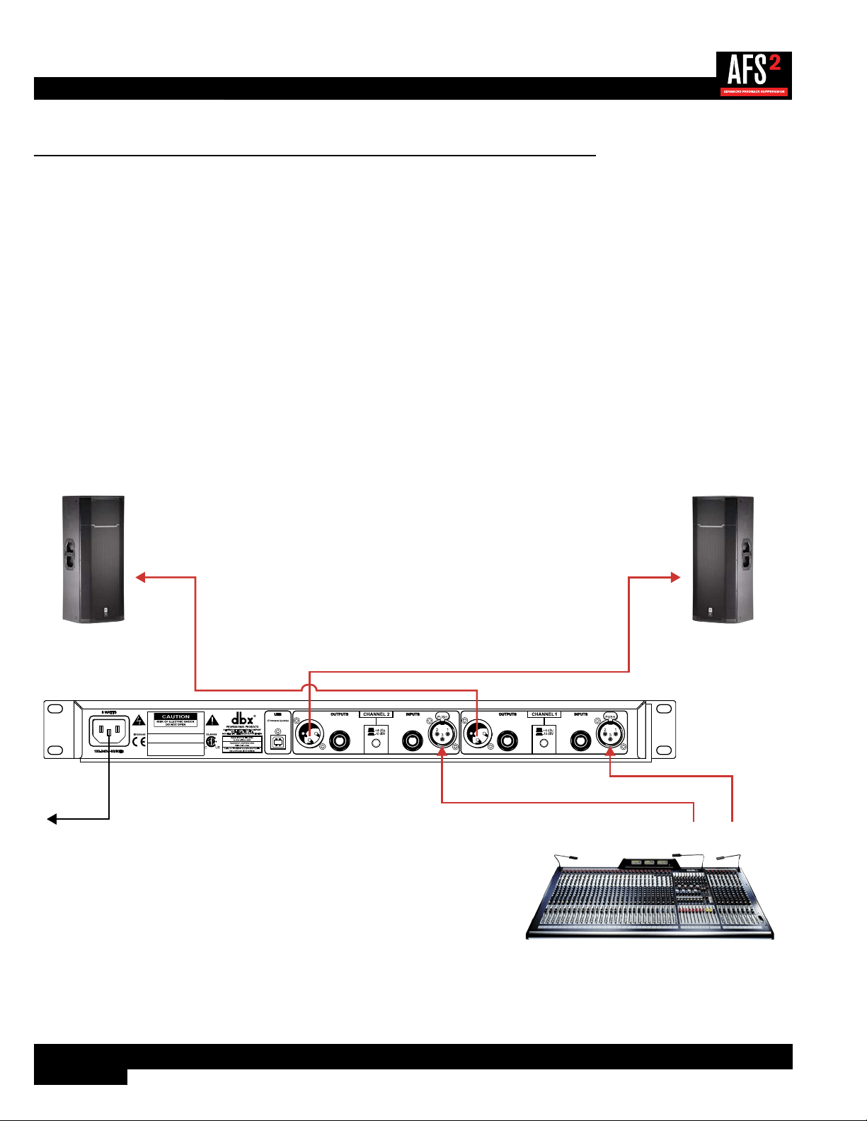
Application 4 – In-line Between Mixer & Amp
Use this configuration to protect the entire system from feedback when your mixer doesn’t have master insert connections. If
your mixer does have master insert connections, it is recommended that you connect the AFS2 to these master insert jacks as
described in ‘Application 3 – Mixer Master Inserts’ on page 9. If you have a system EQ, you can place it before or
after the AFS2 in the chain. This application provides two channels of feedback suppression with up to 24 filters per channel.
Application Notes:
• Ensure all interconnecting equipment is turned off, including the amplifiers or powered speakers.
• Connect the main outputs of the mixer to the inputs of the AFS2.
• Connect the outputs of the AFS2 to the power amplifier’s inputs or the next device in the chain if using a system EQ or
active crossover.
• Apply power to the system, ensuring to turn the amplifiers or powered speakers on last.
• Ensure the AFS2 is configured for stereo (linked) operation, see ‘Linking/Unlinking Channels’ on page 18 for
further information.
WIZARD
20
10
CLIP
3
0
SIG
CH 1
CH 2
INPUT FILTERS
1 2 3 4 5 6 7 8 9 10 11 12 13 14 15 16 17 18 19 20 21 22 23 24
CH 1
CH 2
BYPASS
SELECT
MENU / BACK
AFS WIZARD
Configure Channel 2
Configure as Stereo
Configure Channel 1
A HARMAN INTERNATIONAL COMPANY
SALT LAKE CITY, UTAH
MODEL: AFS2 FEEDBACK SUPPRESSION
WARNING:
TO REDUCE THE RISK OF FIRE
OR ELECTRIC SHOCK DO NOT EXPOSE THIS
EQUIPMENT TO RAIN OR MOISTURE
ATTENTION:
POUR RÉDUIRE LE RISQUE
D'INCENDIE OU D'ÉLECTROCUTION
N'EXPOSEZ PAS CET APPAREIL À LA PLUIE
OU L'HUMIDITÉ
ELECTRIQUE - NE PAS OUVRIR
RISQUE DE CHOC
ATTENTION:
Left Main
Powered Speaker
Right Main
Powered Speaker
Mixer
R Main
Out
L Main
Out
To Power
Outlet
11
The User Interface & Connectors
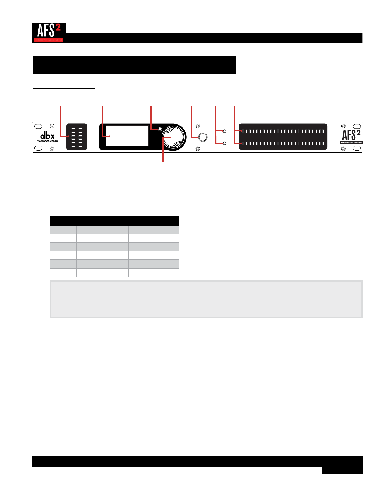
Front Panel
WIZARD
20
10
CLIP
3
0
SIG
CH 1
CH 2
INPUT FILTERS
1 2 3 4 5 6 7 8 9 10 11 12 13 14 15 16 17 18 19 20 21 22 23 24
CH 1
CH 2
BYPASS
SELECT
MENU / BACK
AFS WIZARD
Configure Channel 2
Configure as Stereo
Configure Channel 1
1 2 3
4
5 6 7
1. Input Level Meters w/Clip Indicator
These LED meters show the incoming signal level of each channel and indicate when the input signal is clipping. Input
level LEDs range from -28 dBu (SIG) to +22 dBu (CLIP). The below table shows the correlation between the input
meter LEDs and signal level depending on the +4 dBu/-10 dBV switch position on the rear panel.
Input LEDs (switch set to +4 dBu) (switch set to -10 dBV)
CLIP 22 dBu 8 dBV
0 19.9 dBu 5.9 dBV
3 17 dBu 3 dBV
10 10 dBu -4 dBV
20 0 dBu -14 dBV
SIG -28 dBu -42 dBV
NOTE: AFS works best when the signal entering the AFS2’s inputs is sufficient. This requires proper gain staging
between the mixer and AFS2. For maximum performance and proper operation, the average input signal level should
consistently light the ‘20’ LED, with the ‘10’ LED lighting occasionally. If the signal level is too low, AFS may be slow
to respond to feedback. See ‘Gain Structure’ on page 6 for further information on gain structure.
2. LCD Display
This LED backlit LCD display provides the visual cues necessary for navigating and operating the AFS2.
3. MENU/BACK Button
Pressing this button from the Information View Home Screen in Home Mode will enter the AFS2 menus. Pressing it
from the Filter Plot Home Screen will return to the Information View Home Screen. Pressing it when in any menu will
move back one level in the current menu hierarchy. Pressing it from the first screen in the menu hierarchy will return to
Home Mode.
4. DATA Wheel
This encoder is used for making on-screen selections and editing parameters. Pressing this DATA wheel from Home
Mode will also toggle between the two available Home Screens. One screen shows detailed information about each set
filter (i.e., the width, attenuation amount, and set frequency) and the other displays a graphical representation of the set
AFS notch filters. See ‘Navigating & Modes Of Operation’ on page 14 for further information on these Home
Screens.

12
5. WIZARD Button
Press this button to enter the Wizard, which will walk you through the entire AFS2 setup and ring-out procedure.
6. BYPASS Buttons
Pressing these buttons will enable and bypass the AFS filters in each channel. When each button’s LED is lit, the
channel is bypassed. Note that when the AFS2 is configured for stereo linked operation, these bypass buttons will also
be linked. Pressing and holding a channel’s BYPASS button will bring up a menu where you can quickly clear just the
Live filters or all filters for the channel.
WARNING! If AFS is enabled and filters are set, be careful when bypassing the filters as all filters will be
immediately removed from the signal path and sudden feedback could occur. It is recommended that you lower the
mixer outputs feeding the AFS2 before bypassing any AFS filters with the BYPASS buttons.
7. Filter Status LEDs
These LEDs indicate how many filters have been set in each channel – each lit LED indicates a set Fixed or Live filter.
13
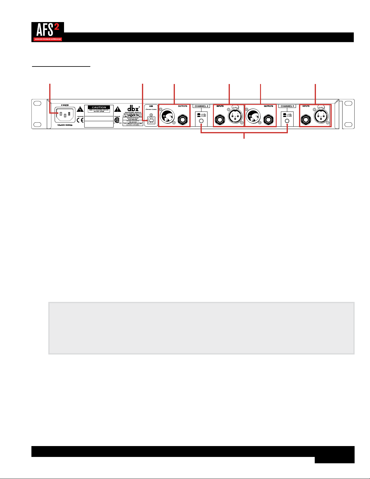
Rear Panel
A HARMAN INTERNATIONAL COMPANY
SALT LAKE CITY, UTAH
MODEL: AFS2 FEEDBACK SUPPRESSION
WARNING:
TO REDUCE THE RISK OF FIRE
OR ELECTRIC SHOCK DO NOT EXPOSE THIS
EQUIPMENT TO RAIN OR MOISTURE
ATTENTION:
POUR RÉDUIRE LE RISQUE
D'INCENDIE OU D'ÉLECTROCUTION
N'EXPOSEZ PAS CET APPAREIL À LA PLUIE
OU L'HUMIDITÉ
ELECTRIQUE - NE PAS OUVRIR
RISQUE DE CHOC
ATTENTION:
1 2
5
3 4 3 4
1. Power Connector
Connect the included IEC power cord to this connector and the other end to an available AC outlet.
2. USB Connector
This connector is used for updating the firmware in the AFS2 from a connected computer. As firmware updates become
available, they will be found on the AFS2 product page at dbxpro.com.
3. Output Connectors
Two types of balanced output connectors are provided for output connections: male XLR type connectors and 1/4"
tip-ring-sleeve phone connectors.
4. Input Connectors
Two types of balanced input connectors are provided for input connections: female locking XLR type connectors and
1/4" tip-ring-sleeve phone connectors. Either of these input connector types can be used with balanced or unbalanced
connections. The maximum input level that the processor can accept is +20 dBu (ref: 0.775 Vrms).
5. Operating Level Switches
These switches allow you to select between a nominal operating level of either +4 dBu or -10 dBV for each channel.
Use these switches to match the operating level of the AFS2 to the interconnecting equipment.
NOTE: The +4 dBu/-10 dBV switch on the back panel of the AFS2 must be set to the correct position for your
application in order to avoid performance issues. +4 dBu is referred to as ‘pro level’ and will be the correct setting for
most applications, as most pro and semi-pro mixers will output a nominal level of around +4 dBu. -10 dBV is referred
to as ‘consumer level’ and will need to be used when connecting a device which has an output level approximately 12
dB lower than pro level equipment. If you’re unsure of the nominal operating level of your device’s connections, take a
look at the device’s manual or contact the device manufacturer.
14
Operating The AFS2
Navigating & Modes Of Operation
There are three modes of operation in the AFS2, they are: Home Mode, Menu Mode, and Wizard Mode.
Home Mode
This is the operating mode which the AFS2 enters after power-up and initialization. There are two Home Screens which can be
viewed from Home Mode. To toggle between the two available Home Screens, just press the DATA wheel from Home Mode.
When viewing either Home Screen, turn the DATA wheel to select a filter. As each filter is selected, the channel and filter
assignment numbers for the selected filter will be displayed at the bottom of the screen. As each ‘set’ filter is selected, the
filter’s properties will also be displayed at the bottom of the screen. The filter properties displayed are:
• Center Frequency – This is the frequency of the center point of the filter.
• Attenuation Amount – This is the amount of attenuation applied at the filter’s center
frequency.
• Q – This is the width of the filter represented in ‘Quality’ factor or ‘Q’ factor. A Higher Q
value represents a narrower filter and a lower Q value represents a wider filter.
Center Frequency
Attenuation
Amount
Q Factor
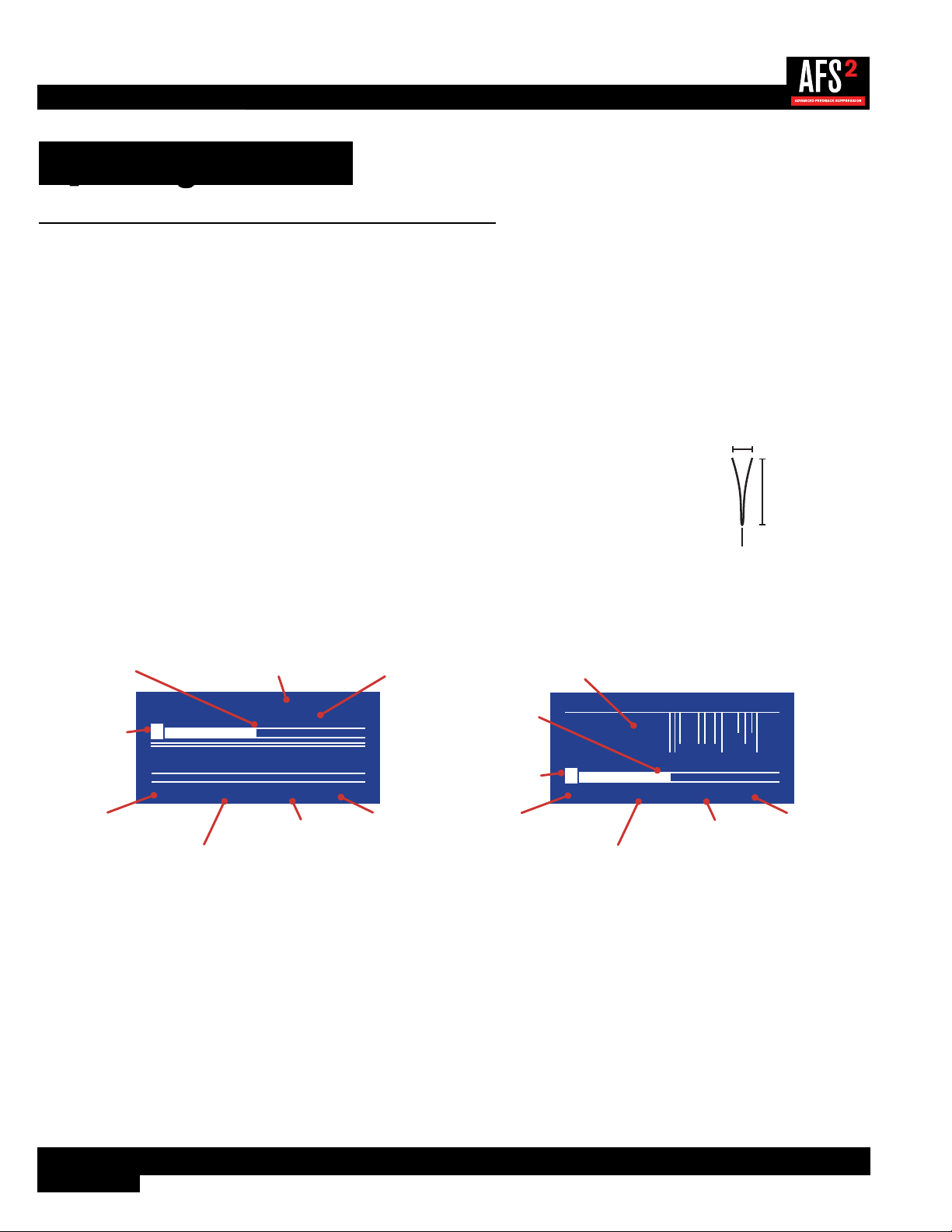
The two available Home Screens are shown below.
Information View Home Screen Filter Plot Home Screen
CHAN.1
F
FIXED
CH:
1-1 500Hz -12.0dB 7
F F F F F F F F F F F
L L L L L L L L L L L
L L L L L L L L L L LF F F F F F F F F F L
SP/MUS
LIVE
SPEECH
CHAN.2
Selected Channel/Filter #
Filter Center Frequency
Filter Mode Content ModeAFS Filters
(F=Fixed, L=Live)
(White Box=Set Filters)
Filter Attenuation Amount
Filter Q Factor
Selected Filter
F
F F F F F F F F F F F
L L L L L L L L L L L
CH:
1-1 500Hz
100 20k1k20
-12.0dB 7
Selected Channel/Filter #
Filter Center Frequency
Filter Attenuation Amount
Filter Q Factor
Filter/Frequency Graph
Selected Filter
AFS Filters
(F=Fixed, L=Live)
(White Box=Set Filters)
Menu Mode
In Menu Mode you can edit AFS options (these parameters are used when manually ringing out a sound system with AFS),
save and load presets, and edit system parameters. To enter Menu Mode, press the MENU/BACK button from the Information
View Home Screen. If viewing the Filter Plot Home Screen, you can enter Menu Mode by pressing and holding the MENU/
BACK
button for approximately 2 seconds or pressing the MENU/BACK button twice. When navigating in menus, turning the
DATA wheel will select on-screen options. In menus which have two columns, pressing the DATA wheel will jump between
columns, allowing you to jump back and forth between selecting the parameter to edit and then editing the parameter. Turning
the DATA wheel will adjust selected parameters. To see the menu structure and options available in these menus, see ’Menu
Navigation Map’ on page 15.
15
Wizard Mode
This operating mode is entered by pressing the WIZARD button. The Wizard walks you through the configuration and ring-out
procedure with simple, step-by-step instructions. By ringing out the system for feedback, higher system gain can be achieved
before the onset of feedback. This is accomplished by pushing your system into feedback so AFS can detect the frequencies
prone to feedback and then notch them out using Fixed filters. When the AFS Wizard is complete, it will automatically enable
the Live filters for automated protection during system use. See ‘Ringing Out The Sound System’ on page 19 for
further information on using the Wizard.
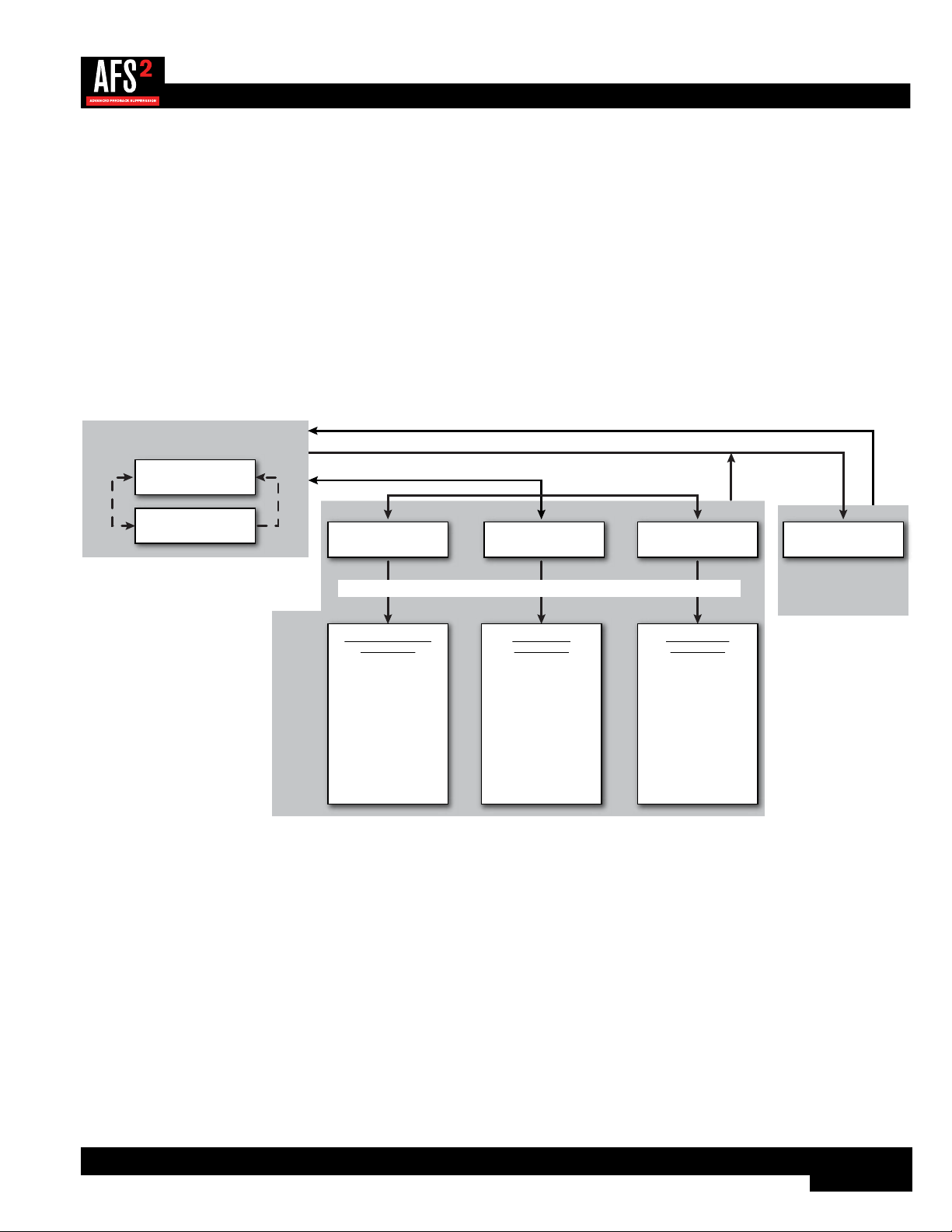
Menu Navigation Map
The below navigation map shows the navigational hierarchy of the AFS2 and how to navigate the unit.
CHANNEL
BYPASS
FILTER MODE
CONTENT MODE
FIXED FILTERS
CLEAR MODE
CLEAR <PRESS SELECT>
LIVE LIFT
LIFT AFTER
VIRTUAL HIGHPASS
SENSITIVITY
AFS Options Menu
Parameters:
LOAD PRESET
SAVE PRESET
FACTORY DEFAULT
Preset Menu
Parameters:
Preset Menu
STEREO LINKED
POWER UP OPTION
DISPLAY TIMEOUT
The currently
installed software
version can also be
found in this menu.
System Menu
Parameters:
AFS Options System Menu AFS Wizard
Information View
Home Screen
Filter Plot
Home Screen
Press the MENU/BACK button
Press the MENU/BACK button
Press the WIZARD button
Press SELECT to
toggle Home Screen
Press MENU/BACK
button
HOME MODE
WIZARD MODE
MENU MODE
Turn the DATA wheel to make selections. Press the DATA wheel to conrm selections.
For further information on the menus and parameters in Menu Mode, see ‘The Menus & Parameters’ on page 24.

16
The AFS Filters
AFS offers two types of filters: Fixed and Live. Fixed filters are set during the initial AFS ring-out procedure. Live filters are
then enabled for protection against new occurrences of feedback during system use. The Live filters in the enhanced AFS
algorithm in the AFS2 can better distinguish between program material and feedback, dramatically lowering the probability of
false Live filters being set on feedback-like music material, such as flute. When you run the AFS Wizard, AFS will automatically
switch between Fixed and Live Mode operation.
Fixed Filters
Fixed filters are active when the FILTER MODE parameter in the AFS OPTIONS menu is set to FIXED. Fixed filters cannot
differentiate between what is music and what is feedback, so these filters are used to initially ring out the sound system before
use and notch out frequencies which are most prone to feedback in the system/venue. This allows the system gain to be
raised without introducing feedback.
NOTE: When in Fixed Mode, the Fixed filters will be allowed to move around and/or widen in order to center themselves
better on offending feedback regions. Upon switching to Live Mode, all Fixed filters will become truly ‘fixed’.
Fixed filters are just that, ‘fixed’. They will remain set – even after power cycling the AFS2 – until they are cleared by the user
or a different preset is loaded, in which case all set Fixed filters in the loaded preset will be set.
Live Filters
Live filters are active when the FILTER MODE parameter in the AFS OPTIONS menu is set to LIVE. Live filters are smarter
than Fixed filters. They have the ability to detect feedback within complex program material. This makes them ideal for
protecting the system from feedback as conditions change during the performance. Live filters also have the ability to detect
when they are no longer needed and can intelligently remove themselves from the chain, effectively restoring sonic fidelity and
freeing up Live filters for use. The parameters that control this behavior are the LIVE LIFT and LIFT AFTER parameters. See
‘The Menus & Parameters’ on page 24 for additional information on these parameters.
If a condition is met where all Live filters have been set, they will begin to round robin – meaning that if all Live filters have
been set and new feedback occurs, the first Live filter set will be released then re-set at the new feedback frequency location.
AFS will continue to round robin through the Live filters as long as all Live filters are set and new feedback is detected.
Filter Widths
The AFS2 offers three filter width options, they are: SPEECH, SPEECH/MUSIC, and MUSIC. The selected option controls the
width of the notch filter used to remove the feedback. These options can be found under the CONTENT MODE parameter in
the AFS OPTIONS menu. See ‘AFS Options Menu’ on page 24 for further information on the CONTENT MODE options.
NOTE: All AFS filters are allowed to widen if necessary in order to tackle wider feedback regions.

17
Clearing Filters
The AFS2 gives you the ability to clear all AFS filters or only the Live filters. Clearing all filters allows you to start from scratch,
for example when ringing out a system in a new venue. Clearing only the Live filters allows you to refresh a system for use, for
example if you’re using the same system in the same venue, but act two is about to begin. There are two methods for clearing
filters; the steps for performing these two methods are outlined below.
WARNING! Ensure the signal level feeding the AFS2 is reduced before clearing filters. Failing to do so may cause
sudden feedback to occur once the filters are cleared.
Method 1 - Clearing filters from the AFS Options menu:
1� From the Home Screen, press the BACK/MENU button. A menu list will be displayed on-screen.
2� Select the AFS OPTIONS menu item by pressing the DATA wheel.
3� Turn the DATA wheel to select the CLEAR MODE parameter then press the DATA wheel.
4� Turn the DATA wheel to select which filters you wish to clear. Select the LIVE ONLY option to clear only the Live filters.
Select the ALL option to clear all Live and Fixed filters.
5� Press the DATA wheel to jump back to the left column then turn the DATA wheel to select the CLEAR <PRESS
SELECT> option.
6� Press the DATA wheel to initiate the clear function.
The second method provides a faster way to clear filters using the BYPASS buttons.
Method 2 - Clearing filters using the BYPASS buttons:
1� Press and hold the CH1 or CH2 BYPASS button for approximately 2 seconds until the FILTER CLEAR menu appears.
2� Turn the DATA wheel to select the desired option then press the DATA wheel to perform the selected clearing function. To
cancel the operation, select the CLEAR NONE option or press the MENU/BACK button.
NOTE: If you’ve configured the AFS2 for stereo linked operation, performing the above procedure will clear filters on
both channels.

18
Linking/Unlinking Channels
Channels can be configured for stereo (linked) or dual mono (unlinked) operation. This option can be configured when you run
the Wizard or manually from the System menu.
NOTE: When linked, the parameters for both channels will be linked but AFS detection and filter placement will not.
In other words, both channels will share the same parameter settings but feedback will be detected and notched out
independently per channel. When clearing filters with the channels linked, both channels will be cleared.
To link/unlink channels manually:
1� From the Home Screen, press the BACK/MENU button.
2� Turn the DATA wheel to select the SYSTEM MENU option then press the DATA wheel to advance.
3� With the STEREO LINK option selected, press the DATA wheel.
4� Turn the DATA wheel to select the desired option – select YES for stereo linked operation or NO for unlinked operation.
5� Press the MENU/BACK button repeatedly to return to the Home Screen.

19
Ringing Out The Sound System
Fixed filters are set before a performance in a process called ‘ringing out a system’. This is done after all other system EQ has
been performed. Ringing out the sound system for feedback before use allows you to squeeze more gain out of the system
before the onset of feedback and can help ensure you’re not right at the edge of feedback during system use.
The AFS2’s Wizard does a great job of taking the guesswork out of ringing out the sound system. However, you can also ring
out the system manually. This allows you to select different filter width settings for the Fixed verses Live filters and precisely
determine how many Fixed filters will be used to maximize the system’s gain before feedback, freeing up all remaining filters
for Live Mode use.
NOTE: AFS works best when the signal coming into the AFS2 is sufficiently optimized. See ‘Gain Structure’ on
page 6 for further information on optimizing the gain structure between your mixer and the AFS2.
Using The Wizard
To use the Wizard, just press the big, red Wizard button and follow the on-screen instructions. It’s as simple as that! Note that
pressing and holding the MENU/BACK button during the Wizard process will abort the procedure and return to the AFS main
menu.
Manual Method
To manually ring out the sound system:
1� Set both channels to bypass using the CH 1/CH 2 BYPASS buttons.
2� Make sure all filters are cleared before beginning, see ‘Clearing Filters’ on page 17 for further information.
3� Perform a sound check and set up a rough mix for all microphones which will be active during the performance. When
done, take note of the mixer’s main output fader position (mixer master sends if ringing out stage monitors or subgroup
faders if ringing out subgroups) – your target gain when ringing out the system will be around 5 dB above this setting.
4� If noise gates are being used on any of the active mics – including vocal effect processors with built-in noise gates –
bypass them before ringing out the system. You can re-enable them once the ring-out procedure is complete.
5� Have the musicians stop playing and fully lower the main mixer faders (mixer master sends if ringing out stage monitors
or subgroup faders if ringing out subgroups).
6� Turn STEREO LINKED on or off depending upon desired operation (see previous page).
7� Set the FILTER MODE parameter to FIXED. This parameter can be found by pressing the BACK/MENU button from the
Home Screen then selecting AFS OPTIONS from the menu.
8� Set the FIXED FILTER parameter in the AFS OPTIONS menu to 12.
9� Set the CONTENT MODE parameter to select the desired width for the Fixed filters – select the MUSIC option for the
most precise and inaudible feedback suppression.
10� Adjust the VIRTUAL HIGH PASS parameter if you do not want to allow AFS to notch out lower frequencies.
11� Ensure the musicians are not playing then unbypass the channels you wish to ring out using the CH 1/CH 2 BYPASS
buttons.
NOTE: When ringing out the system in Fixed Mode, any sustained sound detected by AFS will trigger Fixed filters
to be set. Therefore, make sure the microphones are active, but there is no appreciable signal present at the mics.

20
12� Slowly raise the main mixer faders (mixer master sends if ringing out stage monitors or subgroup faders if ringing out
subgroups) until you reach your target gain (described in step 3) or run out of Fixed filters, whichever happens first.
HINT: When ringing out the system, it sometimes helps to start the ringing by triggering a sharp sound, such as a
finger snap or clap.
HINT: If you run out of Fixed filters in the above step and haven’t yet reached your target gain, you can go to the
FIXED FILTERS parameter and increase it then repeat the above step.
13� Lower the main mixer faders (mixer master sends if ringing out stage monitors or subgroup faders if ringing out
subgroups) back to performance level – this is the level at which you had the mixer’s fader or send during sound check in
step 3.
HINT: If there are any allocated Fixed filters which were not set during the ring-out procedure, you can free them
up by lowering the FIXED FILTERS parameter. This will set the unused Fixed filters to Live filters so they can be
utilized. Make sure not to lower the FIXED FILTERS parameter beyond the amount of unused Fixed filters as doing
so will remove Fixed filters you just set. In other words, if the FIXED FILTERS parameter is set to 18 and you have 2
unused Fixed filters, you would want to lower the FIXED FILTERS parameter by 2 and no more.
14� Set the FILTER MODE parameter to LIVE.
15� Go to the CONTENT MODE parameter and select the desired width for the Live filters – select the MUSIC/SPEECH
option for the best all around real-time feedback protection. Select the MUSIC option if sonic quality is of the utmost
importance. Select the SPEECH option if feedback suppression speed is of the utmost importance.
16� Set the LIVE LIFT and LIFT AFTER parameters per your application. See ‘The Menus & Parameters’ on page 24
for further information on these parameters.
17� The system is now ready for use and any available Live filters will be available for on-the-fly feedback suppression during
the performance.
HINT: When ringing out the system, you can change the CONTENT MODE parameter at any time. This will change the
filter width for any new filters set, but will not change the width of filters already set. For example, you could use the high
precision ‘MUSIC’ setting when ringing out the system with the Fixed filters, then switch over to the ‘SPEECH/MUSIC’
setting for the Live filters for slightly faster feedback suppression during the performance.

21
Presets
Saving Presets
Up to 5 user presets can be stored in the AFS2 for later recall. When saving presets, the following settings will be saved:
• All Set Fixed Filters (Gain/Q/Frequency values)
• Fixed Filters Parameter Setting (number of Fixed vs. Live filters)
• Content Mode Parameter Setting (filter width)
• Live Lift Enable Parameter Setting
• Lift Time Parameter Setting
• Stereo Link Parameter Setting
• Virtual High Pass Parameter Setting
• Sensitivity Parameter Setting
To save a preset:
1� From the Home Screen, press the BACK/MENU button.
2� Turn the DATA wheel to select the PRESET MENU option then press the DATA wheel to advance.
3� Turn the DATA wheel to select the SAVE PRESET option then press the DATA wheel to advance.
4� Turn the DATA wheel to select the preset memory location at which the preset will be saved.
NOTE: Any settings currently saved to the selected preset will be overwritten.
5� Press the DATA wheel to save the settings to the selected preset location.
Loading Presets
To load a preset:
1� From the Home Screen, press the BACK/MENU button.
2� Turn the DATA wheel to select the PRESET MENU option then press the DATA wheel to advance.
3� Select the LOAD PRESET option then press the DATA wheel to advance.
4� Turn the DATA wheel to select the preset to load.
5� Press the DATA wheel to load the selected preset.

22
Front Panel Lockout
The AFS2’s front panel controls can be locked to prevent unauthorized tampering. When the front panel is locked, a 4-digit PIN
must be entered to unlock the unit and make any parameter changes. The PIN is a fixed number and is ‘1234’ .
To enable system lockout:
1� From the Home Screen, press the MENU/BACK button.
2� Turn the DATA wheel to select the SYSTEM MENU option then press the DATA wheel to advance.
3� Turn the DATA wheel to select the DISPLAY TIMEOUT option then press the DATA wheel.
4� Turn the DATA wheel to select the amount of time it will take for the front panel to lock after no user activity.
5� Press the MENU/BACK button repeatedly to return to the Home Screen.
To enter the PIN and unlock the front panel:
1� Turn the DATA wheel and select the number 1.
2� Press the DATA wheel to enter 1 as the first number of the PIN.
3� Turn the DATA wheel and select the number 2.
4� Press the DATA wheel to enter 2 as the second number of the PIN.
5� Turn the DATA wheel and select the number 3.
6� Press the DATA wheel to enter 3 as the third number of the PIN.
7� Turn the DATA wheel and select the number 4.
8� Press the DATA wheel to enter 4 as the fourth number of the PIN.

23
Factory Resets
WARNING! Performing these resets will clear all set filters. Ensure the system’s gain is reduced before performing
these procedures to ensure the system does not go into feedback once the filters are cleared.
Factory Default Reset
This reset option can be found in the PRESET menu and is used to reset all current AFS2 settings back to their factory default
state. Note that this reset will not overwrite presets.
The Factory Default Reset will reset the following parameters back to their factory default state:
• All set AFS filters.
• All parmeters in the AFS OPTIONS menu.
• All parameters in the SYSTEM menu.
To perform a Factory Default Reset:
1� From the Home Screen, press the BACK/MENU button.
2� Turn the DATA wheel to select the PRESET MENU option then press the DATA wheel to advance.
3� Turn the DATA wheel to select the FACTORY DEFAULT option then press the DATA wheel to begin the procedure.
Factory Hard Reset
This reset option involves a boot sequence and can be used to reset all settings (including presets) back to their factory default
state.
The Factory Hard Reset will reset the following parameters back to their factory default state:
• All set AFS filters.
• All parmeters in the AFS OPTIONS menu.
• All parameters in the SYSTEM menu.
• All presets.
To perform a Factory Hard Reset:
1� While powering on the AFS2, press and hold both the CH1 and CH2 BYPASS buttons until the reset confirmation prompt
appears on-screen.
2� Select the YES option with the DATA wheel then press the DATA wheel to confirm the selection and begin the procedure.
Select the NO option or press the MENU/BACK button to abort the procedure.

24
The Menus & Parameters
AFS Options Menu
The AFS Options menu houses all the parameters for the two channels. Following is a description of all the parameters found
in this menu.
CHANNEL [1, 2]
This parameter selects the channel to edit.
BYPASS [ON, OFF]
This parameter bypasses the selected channel and will override the channel’s BYPASS button on the front panel.
FILTER MODE [FIXED, LIVE]
This parameter determines whether the AFS algorithm will set Live or Fixed filters. See ‘The AFS Filters’ on page 16 for
further information on Fixed and Live filters.
CONTENT MODE [SPEECH, MUSIC, MUSIC/SPEECH]
This parameter sets the width of the AFS filters. The available options are:
• SPEECH (Constant bandwidth of 11 Hz below 76 Hz, constant Q of 7 at or above 76 Hz)
This option is optimized for speech sound reinforcement, where wider notch filters are less noticeable. Select this option
when using the sound reinforcement system for speech only. With this option selected, notch filters will be wider but will
provide the fastest, most solid protection against feedback.
• MUSIC (Constant bandwidth of 8 Hz below 927 Hz, constant Q of 116 at or above 927 Hz)
This option is optimized for live music sound reinforcement and offers the highest level of sonic quality. When this option
is selected, the AFS algorithm will zero in on the offending feedback frequency while leaving the surrounding frequencies
unscathed.
• MUSIC/SPEECH (Constant bandwidth of 9 Hz below 260 Hz, constant Q of 29 at or above 260 Hz)
This option is optimized for live music sound reinforcement or speech and provides the best all-around protection. It will
provide the best combination of fast feedback suppression and precision, using filters slightly narrower and less audible
than the SPEECH setting, but slightly faster than the MUSIC setting. If you’re not sure which setting to use, select this
option.
NOTE: To guarantee that feedback is suppressed using the minimum number of filters possible, AFS may
automatically widen filters. For example, if you had selected the MUSIC setting and an adjacent frequency is feeding
back, AFS will detect both frequencies, and if they are in close enough proximity, will set a single, wider filter rather than
two narrow filters. Using a single, wider filter rather than two narrow filters will not alter the sonic quality and will ensure
that the maximum number of filters will always be available for use. Automatically adjusted filter widths will never be any
wider than the SPEECH setting.

25
FIXED FILTERS [0 - 24]
This parameter sets how many of the AFS filters will be allocated as Fixed filters. There are a total of 24 AFS filters available.
The number of Live filters is the difference between the total number of filters and the number of Fixed filters. For example, if
you select a FIXED FILTER setting of 12, you will have 12 Live filters available for use (24 - 12 = 12).
HINT: Since it’s not really possible to predict exactly how many Fixed filters you may need, a good setting to start with is
the default setting of 12. If you feel you need to squeeze more gain out of the system after the ring-out procedure, you can
increase the FIXED FILTERS setting and run the AFS Wizard again or manually ring out only the newly added Fixed filters
in the AFS OPTIONS menu.
NOTE: If the FIXED FILTERS setting is changed after filters have been set, the filters will be cleared one by one as you
increase or decrease the setting. For example, if you decrease the FIXED FILTERS setting by one, the last Fixed filter set
will be cleared because the Fixed filter will be changed to a Live filter. Likewise, if the FIXED FILTERS setting is increased
by one (and thus the number of Live filters goes down), then the first Live filter set will be cleared. The Fixed/Live filter
allocation is indicated at the bottom of the LCD display in the Home Screen or in the AFS OPTIONS menu. ‘F’ indicates
Fixed filters and ‘L’ indicates Live filters. A highlighted F or L indicates a filter that is set, or in use.
CLEAR MODE [ALL, LIVE ONLY]
This parameter lets you select whether you would like to clear all filters (Live and Fixed) or only the Live filters.
CLEAR <PRESS SELECT>
Selecting this option then pressing the DATA wheel will clear set filters. Which filters will be cleared is determined by the option
selected for the CLEAR MODE parameter. See ‘Clearing Filters’ on page 17 for more information on clearing filters.
LIVE LIFT [ON, OFF]
This parameter turns the LIVE LIFT feature on and off. When turned on, this parameter enables a timer for each Live filter.
Turn LIVE LIFT on when you want AFS to lift Live filters after a predetermined time set by the LIFT AFTER parameter. Higher
fidelity can be restored to the system by lifting Live filters when they are no longer needed (for example, if a singer steps to
the front of the stage and triggers feedback, setting a Live filter, and then backs off).
If LIVE LIFT is off, the Live filters will remain in place until they are cleared by the user, the unit is power cycled, or a different
preset is loaded.
LIFT AFTER [5S - 60M]
When the LIVE LIFT parameter is turned on, this parameter determines how long it will take before AFS will attempt to lift
a set Live filter. The selectable options range from 5S (5 seconds) to 60M (60 minutes). Once a timer has expired, AFS will
slowly release the Live filter by 3 dB increments to determine if it is safe to remove it. If it gets to 0 dB and no feedback
reoccurs, the filters are completely lifted. If feedback attempts to reappear while releasing, the filter is once again set and the
timer resets. This helps prevent a sudden reoccurrence of blaring feedback in the event a Live filter is still needed and should
remain set.

26
VIRTUAL HIGH PASS [OFF, 30Hz - 500Hz]
This parameter places a high pass filter in the AFS detector path. If you don’t want AFS to have the ability to set any filters
below a set frequency (for example, if you don’t want AFS to notch any frequencies below 100Hz), adjust this parameter to the
frequency below which you want AFS to ignore.
SENSITIVITY [-6.0 dB to +6.0 dB]
This parameter adjusts the input level feeding the AFS detector and makes AFS more or less prone to mark a signal as
feedback.
When AFS is set to Fixed Mode, SENSITIVITY adjusts the feedback level perceived by AFS. For example, setting SENSITIVITY
to +6 will allow AFS to detect the feedback and notch it out more quickly. Conversely, setting SENSITIVITY to -6 will cause
AFS to be a little more hesitant to set a filter on the feedback until it reaches a higher level.
When AFS is set to Live Mode, SENSITIVITY will work the same way as during Fixed Mode on pure feedback tones, but will
also affect where AFS draws the line between feedback and music. If you find that AFS is being too hesitant to set filters on
feedback during your live performance, try increasing the SENSITIVITY setting. If you find AFS mistaking an instrument for
feedback, try decreasing the SENSITIVITY setting for that channel.

27
Preset Menu
LOAD PRESET
Select this option to load a previously saved user preset, see ‘Loading Presets’ on page 21 for further information.
SAVE PRESET
Select this option to save the current settings as a preset, see ‘Presets’ on page 21 for further information.
FACTORY DEFAULT
Select this option to set all current settings back to their factory default state. This procedure will not delete presets from
memory. See ‘Factory Resets’ on page 23 for further information on this feature.
System Menu
The System menu allows you to edit global system parameters and view the currently installed firmware version.
STEREO LINK [NO, YES]
This parameter links the AFS2 for stereo linked operation when set to YES. When set to NO the two AFS2 channels will
work independently in dual mono operation. See ‘Linking/Unlinking Channels’ on page 18 for further information on
linking/unlinking channels.
POWER UP OPTION [Current, Preset1, Preset2, Preset3, Preset4, Preset5]
This parameter determines the settings that will be loaded after power-up. If the CURRENT option is selected, the AFS2 will
boot with the same settings it had when it was last powered down. If one of the PRESET options is selected, the AFS2 will
always boot with the settings saved in the selected preset.
DISPLAY TIMEOUT [10S, 30S, 1M, 2M, 3M, 4M, 5M, 10M, 15M, 20M, DISABLED]
This parameter enables/disables a timer which will cause the AFS2 to automatically lock out the front panel after a period of
user inactivity. The time is user selectable and ranges from 10 seconds to 20 minutes. After the set time expires, a PIN entry
page will appear on-screen, requiring the correct PIN to be entered before any AFS parameters can be seen or edited. The
PIN is a fixed number and is ‘1234’ . See ‘Front Panel Lockout’ on page 22 for further information on this feature.
28
Technical Information
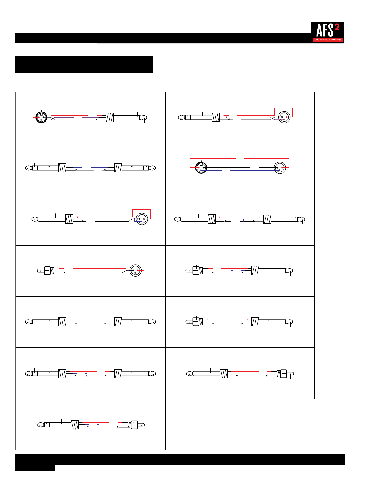
Audio Cable Diagrams
TS PHONE TO TRS PHONE
FROM SOURCE DEVICE (OUTPUT)
TO NEXT DEVICE (INPUT)
TIP
(HOT +)
RING
(COLD -)
SLEEVE
(GROUND)
TIP
(HOT +)
SLEEVE
(GROUND)
HOT +
COLD -
SLEEVE
FROM SOURCE DEVICE (OUTPUT)
TO NEXT DEVICE (INPUT)
TS PHONE TO MALE XLR
1 2
3
HOT +
TIP
(HOT +)
SLEEVE
(GROUND)
SLEEVE
TRS PHONE TO RCA PHONO
FROM SOURCE DEVICE (OUTPUT)
TO NEXT DEVICE (INPUT)
TIP
(HOT +)
RING
(COLD -)
SLEEVE
(GROUND)
HOT +
COLD -
SLEEVE
TIP
(HOT +)
SLEEVE
(GROUND)
FROM SOURCE DEVICE (OUTPUT)
TO NEXT DEVICE (INPUT)
RCA PHONO TO MALE XLR
1 2
3
HOT +
TIP
(HOT +)
SLEEVE
(GROUND)
SLEEVE
RCA PHONO TO TRS PHONE
FROM SOURCE DEVICE (OUTPUT)
TO NEXT DEVICE (INPUT)
TIP
(HOT +)
RING
(COLD -)
SLEEVE
(GROUND)
HOT +
COLD -
SLEEVE
TIP
(HOT +)
SLEEVE
(GROUND)
TS PHONE TO TS PHONE
FROM SOURCE DEVICE (OUTPUT)
TO NEXT DEVICE (INPUT)
TIP
(HOT +)
SLEEVE
(GROUND)
HOT +
TIP
(HOT +)
SLEEVE
(GROUND)
SLEEVE
RCA PHONO TO TS PHONE
FROM SOURCE DEVICE (OUTPUT)
TO NEXT DEVICE (INPUT)
TIP
(HOT +)
SLEEVE
(GROUND)
HOT +
SLEEVE
TIP
(HOT +)
SLEEVE
(GROUND)
TRS PHONE TO TS PHONE
FROM SOURCE DEVICE (OUTPUT)
TO NEXT DEVICE (INPUT)
TIP
(HOT +)
RING
(COLD -)
SLEEVE
(GROUND)
HOT +
TIP
(HOT +)
SLEEVE
(GROUND)
COLD -
SLEEVE
TS PHONE TO RCA PHONO
FROM SOURCE DEVICE (OUTPUT)
TO NEXT DEVICE (INPUT)
TIP
(HOT +)
SLEEVE
(GROUND)
HOT +
SLEEVE
TIP
(HOT +)
SLEEVE
(GROUND)
FROM SOURCE DEVICE (OUTPUT)
TO NEXT DEVICE (INPUT)
FEMALE XLR TO TRS PHONE
2 1
3
HOT +
TIP
(HOT +)
RING
(COLD -)
SLEEVE
(GROUND)
SLEEVE
COLD -
TRS PHONE TO MALE XLR
FROM SOURCE DEVICE (OUTPUT)
TO NEXT DEVICE (INPUT)
1 2
3
HOT +
TIP
(HOT +)
RING
(COLD -)
SLEEVE
(GROUND)
SLEEVE
COLD -
TRS PHONE TO TRS PHONE
FROM SOURCE DEVICE (OUTPUT)
TO NEXT DEVICE (INPUT)
TIP
(HOT +)
RING
(COLD -)
SLEEVE
(GROUND)
HOT +
TIP
(HOT +)
RING
(COLD -)
SLEEVE
(GROUND)
COLD -
SLEEVE
FROM SOURCE DEVICE (OUTPUT)
TO NEXT DEVICE (INPUT)
FEMALE XLR TO MALE XLR
2 1
3
1 2
3
HOT +
SLEEVE
COLD -
29
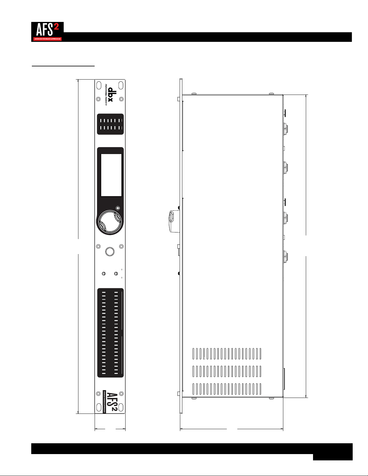
Dimensions
WIZARD
20
10
CLIP
3
0
SIG
CH 1
CH 2
INPUT FILTERS
1 2 3 4 5 6 7 8 9 10 11 12 13 14 15 16 17 18 19 20 21 22 23 24
CH 1
CH 2
BYPASS
SELECT
MENU / BACK
19”
1.75”
17.25”
5.875”

30
Specifications
ANALOG INPUTS:
Number of Inputs: 2
Connectors: Female XLR and 1/4" TRS
Type: Electronically balanced/unbalanced, RF filtered
Impedance: Balanced 50kΩ, Unbalanced 25kΩ
Max input line level: +20dBu
CMRR: >40dB, typically >55dB @ 1kHz
ANALOG OUTPUTS:
Number of Outputs: 2
Connectors: Male XLR and 1/4" TRS
Type: Electronically balanced/unbalanced, RF filtered
Impedance: Balanced >120Ω, unbalanced >60Ω
Max Output Level: +20dBu
A/D PERFORMANCE:
Type: dbx Type IV™ conversion system
Dynamic Range: >110dB A-weighted, >107dB unweighted, 22kHz BW
Type IV™ dynamic range: >119dB, A-weighted, 22kHz BW
>117dB, unweighted, 22kHz BW
A/D Conversion: 24-bit
D/A PERFORMANCE:
Dynamic Range: 112dB A-weighted, 109dB unweighted
D/A Conversion: 24-bit
SYSTEM PERFORMANCE:
Sample Rate: 48kHz
Dynamic Range: >107dB A-weighted, >104dB unweighted, 22kHz BW
THD+N: 0.004% typical at 1Vrms input, 1KHz at +4 dBu
0.006% typical at 0.2Vrms input, 1KHz at -10 dBV
Frequency Response: 20Hz – 20kHz, +/- 1.0dB
Interchannel Crosstalk: >100dB typical
Crosstalk input to output: >100dB typical
Operating Temperature: 0º to 40º C (32º to 104º F)
POWER
Operating Voltage: 100-240VAC, 50Hz/60Hz
Power Consumption: 8 Watts
PHYSICAL
Unit Weight: 4.5 lbs. (2.04 kg)
Dimensions: 1.75" (H) x 5.875" (D) x 19" (W)
4.45cm (H) x 14.92cm (D) x 48.26cm (W)
Specifications are subject to change without notice.