Operator's Manual
III I IIIIII
LAWN TRACTOR
26.0 HR* 54" Mower
Electric Start
Automatic Transmission
Model No.
917,28008
* EspaSol, p. 37
l
This product has a low emission engine which operates
differently from previously built engines. Before you start the
engine, read and understand this Owner's Manual.
IMPORTANT:
Read and follow all Safety
Rules and Instructions before
operating this equipment.
For answers to your questions
about this product, Call:
1-800-659-5917
SEARS Craftsman Help Line
5 am - 5 pm, Mon - Sat
Gasoline containing up to 10% ethanol (El0) is acceptable for use in this machine.
The use of any gasoline exceeding 10% ethanol (El0) will void the product warranty.
Esta maquina puede utilizar gasolina con un contenido de hasta el 10% de etano! (El0),
El uso de una gasolina que supere el 10% de etanol (El0) anular_ la garantia del product<),
Sears Brands Management Corporation, Hoffman Estates, IL 60179 U.S.A.
Visit our Craftsman website:www.sears.com/craftsman *Asratedbytheenginemanufacturer
441521 Rev. 1
Warranty .................................................. 2
Safety Rules ............................................ 3
Product Specifications ............................. 6
AssemblyiPre-O peration ......................... 8
Operation ............................................... 13
Maintenance Schedule .......................... 21
Maintenance .......................................... 21
Service and Adjustments ....................... 26
Storage .................................................. 31
Troubleshooting ..................................... 32
Sears Service .......................... Back Cover
Craftsman Riding Equipment Warranty
CRAFTSMAN FULL WARRANTY
FOR TWO YEARS from the date of purchase, all non-expendable parts of this riding equipment are
warranted against any defects in material or workmanship. A defective non-expendable part will
receive free in-home repair or replacement if repair is impossible.
FOR FIVE YEARS from the date of purchase, the frame and front axle of this riding equipment are
warranted against any defects in material or workmanship. A defective frame or front axle will receive
free in-home repair or replacement if repair is impossibIe.
FOR 90 DAYS from the date of purchase, the battery (an expendable part) of this riding equipment
is warranted against any defects in material or workmanship (our testing proves that it will net hold a
charge). A defective battery will receive free in-home replacement.
ADDITIONAL LIFETIME LIMITED WARRANTY on CAST IRON FRONT AXLE (if equipped)
FOR AS LONG AS IT IS USED by the original owner after the fifth year from the date of purchase, the
cast iron front axle (if equipped) of this riding equipment is warranted against any defects in material or
workmanship. With proof of purchase, a defective cast front axle wilI receive free in-home replacement.
WARRANTY SERVICE
For warranty coverage details to obtain free repair or replacement, call 1-800-659-5917 or visit the
web site: w,_tw,craftsman.com
In al! cases above, if part repair or replacement is impossible, the riding equipment will be replaced
free of charge with the same or an equivalent mode!.
Alt of the above warranty coverage is void if this riding equipment is ever used while providing
commercial services or if rented to another person.
This warranty covers ONLY defects in material and workmanship. Warranty coverage does NOT
include:
• Expendable parts (except battery) that can wear out from normal use within the warranty period,
including but not limited to blades, spark ptugs, air cleaners, belts, and oil filters.
• Standard maintenance servicing, oit changes, or tune-ups.
• Tire replacement or repair caused by punctures from outside objects, such as nails, thorns,
stumps, or glass.
• Tire or wheel replacement er repair resulting from normal wear, accident, or improper operation or
maintenance.
• Repairs necessary because of operator abuse, including but not limited to damage caused by
towing objects beyond the capabi!ity of the riding equipment, impacting objects that bend the
frame, axle assembly or crankshaft, or over-speeding the engine,
• Repairs necessary because of operator negligence, including but not limited to, electrical and
mechanica} damage caused by improper storage, failure to use the proper grade and amount
of engine oi!, failure to keep the deck clear of flammable debris, or failure to maintain the riding
equipment according to the instructions contained in the operator's manual.
• Engine (fue! system) cleaning or repairs caused by fuel determined to be contaminated or oxidized
(stale). tn general, fuel should be used within 30 days ef its purchase date.
• Normal deterioration and wear of the exterior finishes, or product label replacement.
This warranty gives you specific legal rights, and you may also have other rights which vary from
state to state.
Sears Brands Management Corporation, Hoffman Estates, IL 60179
2
_,DANGER: This cutting machine is capable of amputating hands and feet and
throwing objects. Failure to observe the following safety instructions could result
in serious injury'or death.
_,WARNING: In order to prevent accidem
tal starting when setting up, transporting,
adjusting or making repairs, always discon-
nect spark plug wire and place wire where
it cannot contact spark plug.
_WARNtNG: De not coast down a hill in
neutral, you may lose control of the tractor.
,I_WARNING: Tow only the attachments
that are recommended by and comply with
specifications of the manufacturer of your
tractor. Use common sense when towing.
Operate only at the lowest possible speed
when on a slope. Too heavy of a load, while
on a slope, is dangerous. Tires can tose
traction with the ground and cause you to
lose control of your tractor.
_I_WARN1NG: Engine exhaust, some of
its constituents, and certain vehicle compo-
nents contain or emit chemicals known to the
State of California to cause cancer and birth
defects or other reproductive harm.
,_WARNtNG: Battery posts, terminals and
related accessories contain lead and lead
compounds, chemicals known tothe State of
California to cause cancer and birth defects
or other reproductive harm. Wash hands
after handling.
i. GENERAL OPERATION
• Read, understand, andfollowaUinstruc-
tions on the machine and in the manual
before starting.
• Do not put hands or feet near rotating
parts or under the machine, Keep clear
of the discharge opening at all times.
• Only allow responsible adults, who are
familiar with the instructions, to operate
the machine.
• Clear the area of objects such as rocks,
toys, wire, etc,, which could be picked
up and thrown by the blades.
- Be sure the area is clear of bystanders
before operating. Stop machine if anyone
enters the area,
• Never carry passengers.
• Do not mowin reverse unless absolutely
necessary.,Always lookdown and behind
before and while backing.
Never direct discharged material toward
anyone, Avoid discharging material
against a wall or obstruction. Material
may ricochet back toward the operator.
Stop the blades when crossing gravel
surfaces.
• De net operate machine without the en-
tire grass catcher, discharge chute, or
othersafety devices in place and working.
Slow down before turning.
• Never leave a running machine unat-
tended. Always turn off blades, set
parking brake, stop engine, and remove
keys before dismounting.
Disengage blades when not mowing.
Shut off engine and wait for all parts to
come to a complete stop before cleaning
the machine, removing the grass catcher,
or unclogging the discharge chute,
• Operate machine only in daylight or good
artificial light.
• Do not operate the machine while under
the influence of alcohol or drugs.
• Watch for traffic when operating near or
crossing roadways,
• Use extra carewhen loading or unloading
the machine into a trailer or truck,
Always wear eye protection when operat-
ing machine.
• Data indicates that operators, age 60
years and above, are involved in a large
percentage of riding mower*related inju-
ries, These operators should evaluate
their ability to operate the riding mower
safelyenough to protect themselves and
others from serious injury.
• Follow the manufacturer's recommen-
dation for wheel weights or counter-
weights.
Keep machine free of grass, leaves or
other debris build-up which can touch hot
exhaust / engine parts and burn. De not
allow the mower to plow leaves or other
debris which can cause build-up to oc-
cur. Clean any oil or fuel spillage before
operating or storing the machine, Allow
machine to cool before storage,
3
!1. SLOPE OPERATION
Slopes are a major factor related to loss of
control and tip-over accidents, which can
result in severe injury or death. Operation
on all slopes requires extra caution, tf you
cannot back up the slope or if you feet uneasy
on it, do not mow it.
* Mow up and down slopes, not across.
Watch for holes, ruts, bumps, rocks, or
other hidden objects. Uneven terrain
could overturn the machine, Tall grass
can hide obstacles,
° Choose a low ground speed so that you
wilt not have to stop or shift while on the
slope.
, Do not mow on wet grass. Tires may lose
traction.
Always keep the machine in gear when
going down slopes. Do not shiftto neutral
and coast downhill.
, Avoid starting, stopping, or turning on a
slope, tfthetires Iosetraction, disengage
the blades and proceed slowly straight
down the slope.
° Keep all movement on the slopes slow
and gradual. Do not make sudden
changes in speed or direction, which
could cause the machine to roll over.
, Use extracare while operating machine
with grass catchers or other attachments;
they can affect the stability of the ma-
chine. Do no use on steep slopes.
Do not try to stabilize the machine by
putting your foot on the ground.
Do not mow near drop-offs, ditches,
or embankments. The machine could
suddenly roll over if a wheel is over the
edge or if the edge caves in.
Iii, CHILDREN
Tragic accidents can occur if the operator
is not alert to the presence of children.
Children are often attracted to the machine
and the mowing activity, Never assume
that children will remain where you last
saw them,
- Keep children out of the mowing area
and in the watchful care of a responsible
adult other than the operator,
- Be alert and turn machine off if a child
enters the area.
- Before and while backing, look behind
and down for small children.
• Never carry children, even with the
blades shut off. They may fall off and
be seriously injured or interfere with safe
machine operation. Children who have
been given rides in the past maysuddenly
appear in the mowing area for another
ride and be run over or backed over by
the machine.
• Never allow children to operate the ma-
chine.
Use extra care when approaching blind
corners, shrubs, trees, or other objects
that may block your view of a child.
IV. TOWING
, Tow only with a machine that has a hitch
designed for towing. Do not attach towed
equipment except at the hitch point,
• Fottowthemanufacturer'srecommenda-
tion forweight limits for towed equipment
and towing on slopes.
• Never allow children or others in or on
towed equipment.
• Onstopes, theweightofthetowedequip-
ment may cause loss of traction and toss
of control,
• Travel slowly and allow extra distance to
stop.
V, SERVICE
SAFE HANDLING OF GASOLINE
To avoid personal injury or property dam-
age, use extreme care in handling gasoline.
Gasoline is extremely flammable and the
vapors are explosive,
Extinguish all cigarettes, cigars, pipes,
and other sources of ignition.
• Use only approved gasoline container.
• Never remove gas cap or add fuel with
the engine running. Allow engine to coot
before refueling.
Never fuel the machine indoors.
Never store the machine or fuel container
where there is an open flame, spark, or
pilot light such as on a water heater or
other appliances.
• Never fill containers inside a vehicle or
on a truck or trailer bed with plastic liner.
Always place containers on the ground
away from your vehicle when filling.
• Remove gas-powered equipment from
the truck or trailer and refuel it on the
ground. If this is not possible, then refuel
such equipment with a portable container,
rather than from a gasoline dispenser
nozzle,
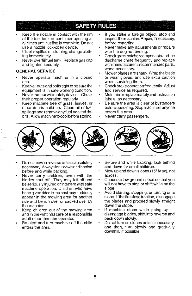
° Keepthenozzleincontactwiththerim
ofthefueltankorcontaineropeningat
alltimesuntilfuelingiscomplete.Donot
useanozzlelock-opendevice.
- Iffuelisspiltedonclothing,changecloth-
ingimmediately.
• Neveroverfillfueltank.Replacegascap
andtightensecurely.
GENERALSERVICE
• Neveroperatemachinein a closed
area.
° Keepallnutsandboltstighttobesurethe
equipmentisinsafeworkingcondition.
- Nevertamperwithsafetydevices.Check
theirproperoperationregularly.
o Keepmachinefreeofgrass,leaves,or
otherdebrisbuild-up.Cleanoilorfuel
spillageandremoveanyfuel-soakedde-
bris.Allowmachinetocoolbeforestoring.
• if youstrikeaforeignobject,stopand
inspectthemachine.Repair,ifnecessary,
beforerestarting.
• Nevermakeanyadjustmentsorrepairs
withtheenginerunning.
• Checkgrasscatchercomponentsandthe
dischargechutefrequentlyandreplace
withmanufacturer'srecommendedparts,
whennecessary.
Mowerbladesaresharp.Wraptheblade
orweargloves,anduseextracaution
whenservicingthem.
• Checkbrakeoperationfrequently.Adjust
andserviceasrequired.
Maintainorreplacesafetyandinstruction
labels,asnecessary.
° Besuretheareaisclearofbystanders
beforeoperating.Stopmachineifanyone
entersthearea.
• Nevercarrypassengers.
• Donotmowinreverseunlessabsolutely
necessary.Alwayslookdownandbehind
beforeandwhilebacking.
Nevercarrychildren,evenwiththe
bladesshutoff.Theymayfalloffand
beseriouslyinjuredorinterferewithsafe
machineoperation.Childrenwhohave
beengivenridesinthepastmaysuddenly
appearinthemowingareaforanother
rideandberunoverorbackedoverby
themachine.
- Keepchildrenoutofthemowingarea
andinthewatchfulcareofaresponsible
adultotherthantheoperator.
• Bealertandturnmachineoffifachild
enters the area.
• Before and while backing, took behind
and down for small children.
Mow up and down slopes (15 ° Max), not
across.
• Choose a low ground speed so that you
will not have to stop or shift while on the
slope.
• Avoid starting, stopping, or turning on a
slope, ifthetireslosetraction, disengage
the blades and proceed slowly straight
down the slope.
• If machine stops while going uphill,
disengage blades, shift into reverse and
back down slowly.
• Do notturn on slopes unless necessary,
and then, turn slowly and gradually
downhill, ff possible.
5

PRODUCT SPECIFICATIONS
Gasoline Capacity 3 Gallons
and Type: Unleaded Regular
Oil Type SAE 10W30(above 32°F)
APt-SG-SL): SAE 5W30(below 32°F)
Oil Capacity: 64 oz.
Spark Plug: Champion RC12YC
(Gap: .030")
Ground Speed Forward: 0-5.2
MPH) Reverse: 0-2.9
Charging System: 15 Amps @ 3600 RPM
Battery: AmpiHr: 28
Min. CCA: 230
Case size: U1R
Blade Bolt 45-55 Ft. Lbs.
Torque:
CONGRATULATIONS on your purchase of
a new tractor. It has been designed, engi-
neered and manufactured to giveyou the best
possible dependability and performance.
Should you experience any problem you can-
not easity remedy, please contact a Sears or
other q ualified service center. We have com-
petent, well-trained representatives and the
proper tools to service or repair this tractor,
Please read and retain this manual. The
instructions will enable you to assemble
and maintain your tractor property, Always
observe the "SAFETY RULES".
CUSTOMER RESPONSIBILITIES
• Read and observe the safety rules,
• Follow a regular schedule in maintaining,
caring for and using your tractor.
• Follow the instructions under "Mainte-
nance" and "Storage" sections of this
owner's manual.
_IbWAR NING: This tractor is equipped with
an internal combustion engine and should not
be used on or near any unimproved forest-
covered, brush-covered or grass-covered
land unless the engine's exhaust system is
equipped with a spark arrester meeting ap-
plicable local or state taws (if any). If a spark
arrester is used, it should be maintained in
effective working order by the operator.
In the state of Calilornia the above is required
by law (Section 4442 of the California Public
Resources Code), Other states may have
similar laws. Federal laws apply on federal
lands. A spark arrester for the muffter is
available through your nearest Sears service
center (See REPAIR PARTS manual).
REPAIR PROTECTION
AGREEMENTS
Congratulations on making a smart purchase.
"Your new Craftsman@ product is designed
and manufactured for years of dependable
operation. But like all products, it may require
repair from time to time. That's when having
a Repair Protection Agreement can save you
money and aggravation.
Purchase a Repair Protection Agreement
now and protect yourself from unexpected
hassle and expense.
Here's what's included in the Agreement:
• Expertservice byour 12,000 professional
repair specialists.
• Unlimited service and no charge for parts
and labor on all covered repairs.
• Product replacement if your covered
product can't be fixed.
• Discount of 10% from regular price of
service and service_related parts not
covered by the agreement; also, t0% off
regular price of preventive maintenance
check.
• Fast help by phone - phone support
from a Sears representative on products
requiring in-home repair, plus convenient
repair scheduling.
Once you purchase the Agreement, a
simple phone call is a!! that it takes for you
to schedule service. You can call anytime
day or night, or schedule a service appoint-
ment online.
Sears has over 12,000 professional repair
specialists, who have access to over 4.5
million quality parts and accessories. That's
the kind of professionalism you can count on
to help prolong the life of your new purchase
for years to come. Purchase your Repair
Protection Agreement today!
Some limitations and exclusions apply.
For prices and additional information call
1-800-827-6655,
SEARS INSTALLATION SERVICE
For Sears professional installation of home
appliances, garage door openers, water
heaters, and other major home items, inthe
U,S.A. call 1-800-4-MY-HOME®
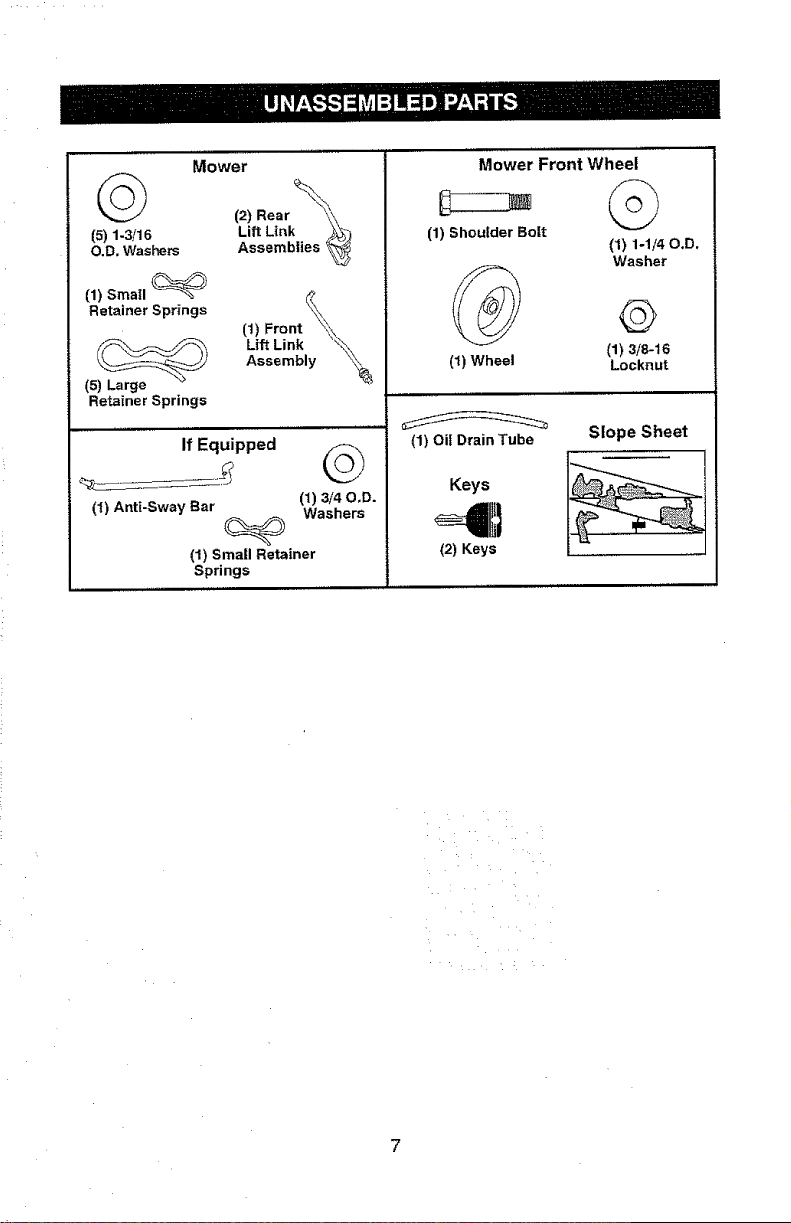
Mower
_t (2) Rear __,
Lift Link _
(5) 1-3/16 AssembliesO.D. Washers
(1) Small
Retainer Springs _
(1) Front _?
Lift Link "_),,
Assembly x,',_
(5) Large
Retainer Springs
,, ,, ...... ,, ,, ,,
If Equipped
(1) Anti-Sway Bar (1) 3/40,D.
Washers
(1) Small Retainer
Springs
Mower Front Wheel
(1) Shoulder Bolt
(1) Wheel
©
(1) 1-1/40.D.
Washer
(1) 3/8-16
Locknut
(1) Oil Drain Tube
Keys
(2) Keys
Slope Sheet
L.....
• • L • •
7
Your new tractor has been assembled at the factory with exception of those parts left
unassembled for shipping purposes. To ensure safe and proper operation of your tractor
all parts and hardware you assemble must be tightened securely, Use the correct tools
as necessary to ensure proper tightness.
TOOLS REQUIRED FOR ASSEMBLY
A socket wrench set will make assembly
easier. Standard wrench sizes are listed.
(2) 7/16" wrenches Utility knife
(1) 1/2" wrench Tire pressure gauge
(1) 3/4" wrench Pliers
(1) 3/4" socket w/drive ratchet
(1) 9/16" wrench Flashlight
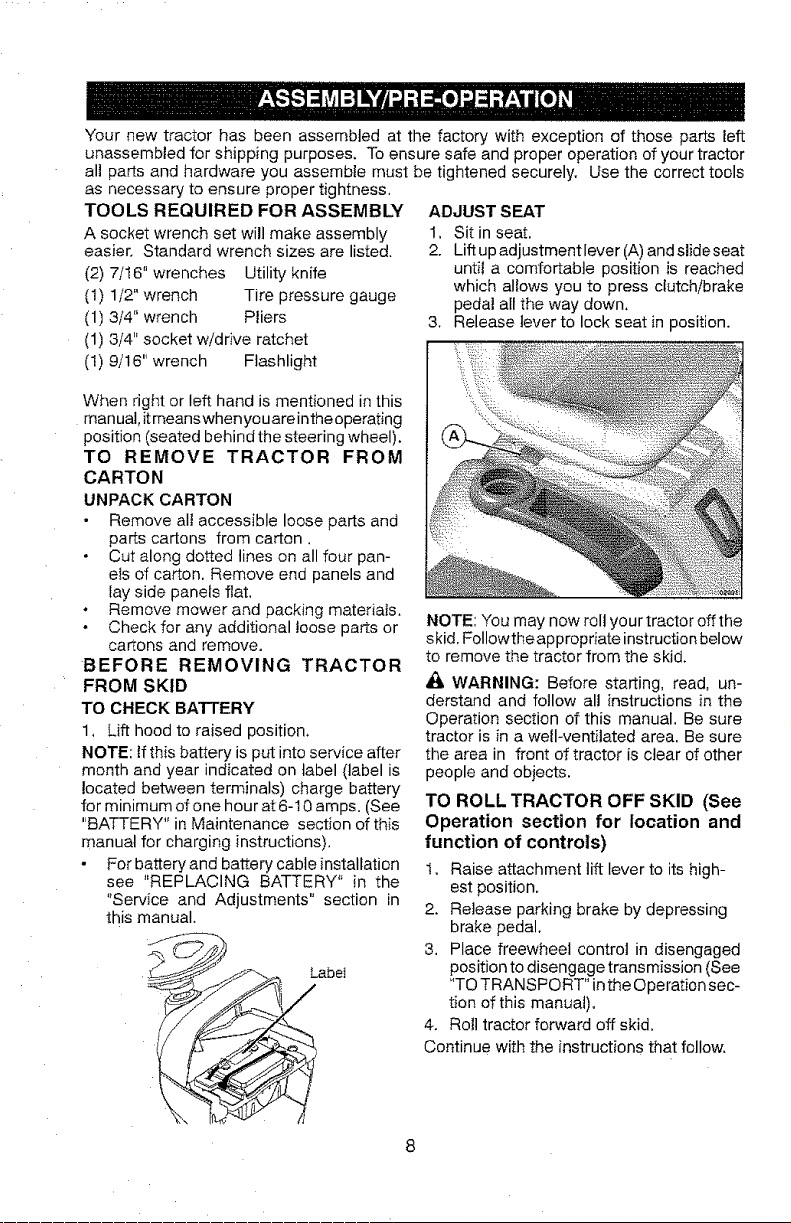
ADJUST S EAT
1, Sit in seat,
2. Lift up adjustmentlever (A) andslideseat
until a comfortable position is reached
which allows you to press clutch/brake
pedal all the way down.
3. Release lever to lock seat in position.
When right or left hand is mentioned in this
manual, itmeanswhenyouareintheoperating
position (seated behind the steering wheel).
TO REMOVE TRACTOR FROM
CARTON
UNPACK CARTON
• Remove all accessible loose parts and
parts cartons from carton,
• Cut along dotted lines on all four pan-
els of carton, Remove end panels and
lay side panels flat,
° Remove mower and packing materials.
° Check for any additional teose parts or
cartons and remove.
BEFORE REMOVING TRACTOR
FROM SKID
TO CHECK BATTERY
1, Lift hood to raised position.
NOTE: if this battery is put into service after
month and year indicated on label (label is
located between terminals) charge battery
for minimum of one hour at 6- t 0 amps. (See
"BATTERY" in Maintenance section of this
manual for charging instructions),
For battery and battery cable installation
see "REPLACING BATTERY" in the
"Service and Adjustments" section in
this manual.
Label
NOTE: You may now roll your tractor off the
skid, Followthe appropriate instruction below
to remove the tractor from the skid.
WARNING: Before starting, read, un-
derstand and follow all instructions in the
Operation section of this manual, Be sure
tractor is in a well-ventilated area, Be sure
the area in front of tractor is clear of other
people and objects.
TO ROLL TRACTOR OFF SKID (See
Operation section for location and
function of controls)
1. Raise attachment lift lever to its high-
est position.
2. Release parking brake by depressing
brake pedal.
3, Place freewheel control in disengaged
position to disengage transmission (See
"TO TRANSPORT" inthe Operation sec-
tion of this manua!).
4. Roll tractor forward off skid,
Continue with the instructions that follow.
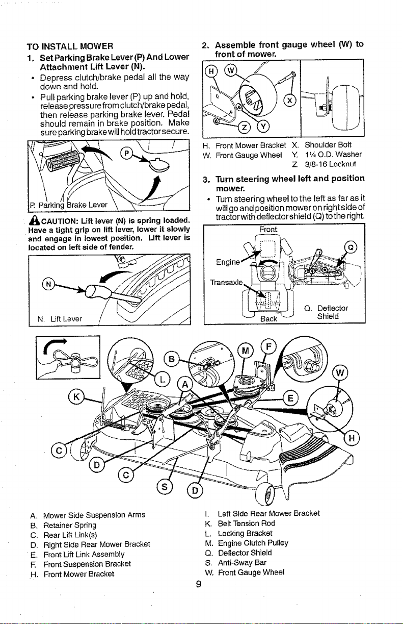
TO INSTALL MOWER
1. Set Parking Brake Lever (P) And Lower
Attachment Lift Lever (N),
, Depress clutch/brake pedal all the way
down and hold.
• Pull parking brake lever CP) up and hold,
release pressure from clutch/brake pedal,
then release parking brake lever. Pedal
should remain in brake position. Make
sure parking brakewill hold tractor secure.
_CAUTION: Lift lever (N} is spring loaded.
Have a tight grip on lift lever, lower it slowly
and engage in lowest position. Lift lever is
located on left side of fender.
2. Assemble front gauge wheel (W) to
front of mower.
H, Front Mower Bracket X, Shoulder Bolt
W. Front Gauge Wheel Y. 1V_O,D. Washer
Z, 3/8-t6 Locknut
3, Turn steering wheel left and position
mower.
• Turn steering wheel to the left as far as it
will go and position mower on right side of
tractorwith deflector shield (Q) tothe right.
Front
TransaxI .J
I _ I Q. Deflector
Back _ Shield
A, Mower Side Suspension Arms
B. Retainer Spring
C. Rear Lift Unk(s)
D. Right Side Rear Mower Bracket
E. Front Lift Unk Assembly
F, Front Suspension Bracket
H, Front Mower Bracket
9
I, Left Side Rear Mower Bracket
K. Belt Tension Rod
L. Locking Bracket
M. Engine Clutch Pulley
Q. Deflector Shield
S. Anti-Sway Bar
W, Front Gauge Wheel
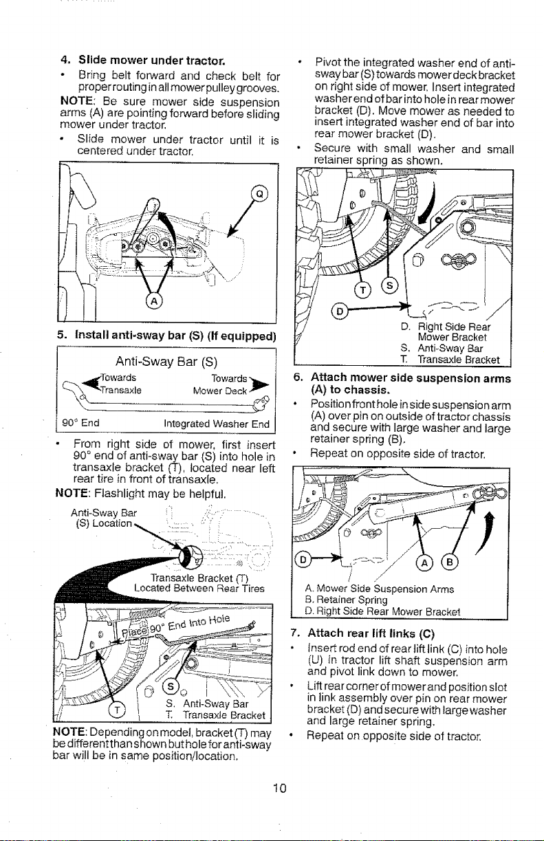
4. Slide mower under tractor.
* Bring belt forward and check belt for
proper routing in all mowerpulley grooves.
NOTE: Be sure mower side suspension
arms (A) are pointing forward before sliding
mower under tractor.
Slide mower under tractor until it is
centered under tractor.
Pivot the integrated washer end of anti-
sway bar (S) towards mower deck bracket
on right side of mower, Insert integrated
washer end of bar into hole in rear mower
bracket (D). Move mower as needed to
insert integrated washer end of bar into
rear mower bracket (D).
Secure with small washer and small
retainer spring as shown,
5. Install anti-sway bar (S) (If equipped)
Anti-Sway Bar (S)
90 ° End Integrated Washer End
From right side of mower, first insert
90 ° end of anti-sway bar (S) into hole in
transaxle bracket (T), located near left
rear tire in front of transaxle,
NOTE: Flashlight may be helpful.
Anti-Sway Bar 'i ,_[:':',: ................
Transaxle Bracket (T)
Located Between Rear Tires
S, Anti-Sway Bar
T, Transaxte Bracket
NOTE: Dependingon model, bracket (T) may
be differentthan shown but hole for anti-sway
bar will be in same position/location,
o080%,,
D, Right Side Rear
Mower Bracket
S. Anti-Sway Bar
T Transaxle Bracket
6. Attach mower side suspension arms
(A) to chassis,
• Position front hole in side suspension arm
(A) over pin on outside of tractor chassis
and secure with large washer and large
retainer spring (B),
• Repeat on opposite side of tractor.
/
A, Mower Side Suspension Arms
B, Retainer Spring
D. Right Side Rear Mower Bracket
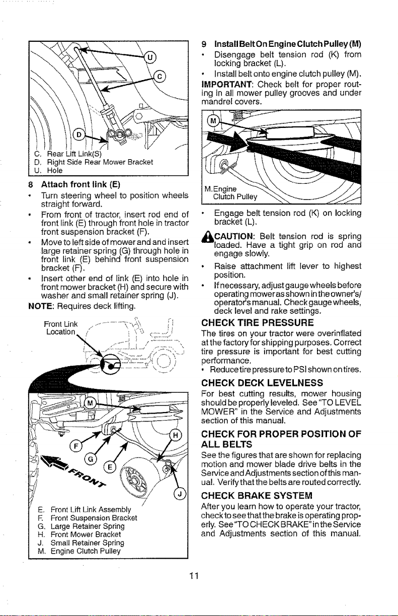
7, Attach rear lift links (C)
Insert rod end of rear lift link (C) into hole
(U) in tractor lift shaft suspension arm
and pivot link down to mower.
• Liftrearcornerofmowerandpositionslot
in link assembly over pin on rear mower
bracket (D) and secure with large washer
and large retainer spring,
• Repeat on opposite side of tractor,
t0
• Bracko,
8 Attach front link (E)
• Turn steering wheel to position wheels
straight forward.
• From front of tractor, insert rod end of
front link (E) through front hole in tractor
front suspension bracket (F).
• Moveto left side of mower and and insert
large retainer spring (G) through hole in
front link (E) behind front suspension
bracket (F),
• Insert other end of link (E) into hole in
front mower bracket (H) and secure with
washer and small retainer spring (J).
NOTE: Requires deck lifting.
i:ns BetonEngnocu,chpu
• Disengage belt tension rod (K) from
locking bracket (L).
Install belt onto engine clutch pulley (M).
IMPORTANT: Check belt for proper rout-
___ ing in all mower pulley grooves and under
mandrel covers.
E. Front Lift Link Assembly
F. Front Suspension Bracket
G. Large Retainer Spring
H. Front Mower Bracket
J. Small Retainer Spring
M. Engine Clutch Pulley
M.Engine
Clutch Pulley
Engage belt tension red (K) on locking
bracket (L),
_CAUTION: Bett tension rod is
spring
loaded. Have a tight grip on rod and
engage slowly.
• Raise attachment lift lever to highest
position,
• Ifnecessary, adjustgaugewheelsbefore
operating moweras shown inthe owners/
operator's manual, Check gauge wheels,
deck level and rake settings.
CHECK TIRE PRESSURE
The tires on your tractor were overinflated
at the factory for shipping purposes. Correct
tire pressure is important for best cutting
performance,
• Reducetire pressureto PSI shown on tires,
CHECK DECK LEVELNESS
For best cutting results, mower housing
should be properly leveled. See "TO LEVEL
MOWER" in the Service and Adjustments
section of this manual,
CHECK FOR PROPER POSITION OF
ALL BELTS
See the figures that are shown for replacing
motion and mower blade drive belts in the
Service and Adjustments section ofthis man-
uaL Verify that the belts are routed correctly.
CHECK BRAKE SYSTEM
After you learn how to operate your tractor,
check to see that the brake is operating prop-
erly. See"TO CHECK BRAKE"intheService
and Adjustments section of this manual,
11
t/f CHECKLIST
Before you operate your new tractor, we
wish to assure that you receive the best
performance and satisfaction from this
Quality Product.
Please review the following checklist:
_/All assembly instructions have been
completed.
J No remaining loose parts in carton.
J'Battery is properly prepared and
charged.
€" Seat is adjusted comfortably and tight-
ened securely.
Z' All tires are properly inflated. (For ship-
ping purposes, the tires were overinflated
at the factory).
vf Be sure mower deck is properly leveled
side-to-sideifront-to-rear for best cutting
results. (Tires must be properly inflated
for leveling).
_/Check mower and drive belts. Be sure
they are routed properly around pulleys
and inside all belt keepers.
vf Check wiring, See that all connections
are still secure and wires are properly
clamped.
,/Before driving tractor, be sure freewheel
control is in "transmission engaged" posi-
tion (see "To Transport" in the Operation
section of this manual).
While learning how to use your tractor, pay
extra attention to the following important
items:
_/ Engine oit is at proper level.
_,/Fuel tank is filled with fresh, clean, regular
unleaded gasoline.
if Become familiar with all controls, their
location and function. Operate them
before you start the engine,
vz Be sure brake system is in safe operating
condition.
J" Be sure Operator Presence System and
Reverse Operation System (ROS) are
working properly (Seethe Operation and
Maintenance sections in this manual).
/ tt is important to purge the transmission
before operating your tractor for the first
time. Follow proper starting and trans-
mission purging instructions (See "TO
START ENGINE" and "PURGE TRANS-
MlSSlON" in the Operation section of this
manual).
t2
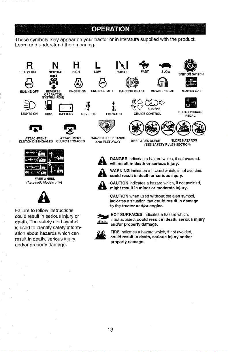
These symbols may appear on your tractor or in literature supplied with the product.
Learn and understand their meaning.
R N H L I',,I
REVERSE NEUTRAL HIGH LOW CHOKE FAST SLOW
141.1
ENGINE OFF REVERSE ENGINE ON ENGINE START PARKING BRAKE MOWER HEIGHT
OPERATION
SYSTEM (ROS)
FUEL
IGNITION SWITCH
MOWERLIFT
LIGHTS ON BA3"TERY REVERSE FORWARD CRUISE CONTROL CLUTCH/BRAKE
PEDAL
ATTACHMENT A'I-FACHMENT DANGER, KEEP HANDS
CLUTCH DISENGAGED CLUTCH ENGAGED AND FEET AWAY
FREE WHEEL
(Automatic Models only)
®@®@@
KEEP AREA CLEAR SLOPE HAZARDS
(SEE SAFETY RULES SECTION)
&
Failure to follow instructions
could result in serious injury or
death. The safety alert symbol
is used to identify safety inform-
ation about hazards which can
result in death, serious injury
andtor property damage.
DANGER indicates a hazard wh}ch, if not avoided,
wilt result in death or serious injury.
WARNING indicates a hazard which, if net avoided,
could result in death or serious injury.
CAUTION indicates a hazard which, if not avoided,
might result in minor or moderate injury.
CAUTION when used without the alert symbol,
indicates a situation that could result in damage
to the tractor and/or engine.
HOT SURFACES indicates a hazard which,
._,_,t_,,. if not avoided, could result in death, serious injury
and/or property damage.
_#j,,j FIRE indicates a hazard which, if not avoided,
could result in death, serious injury and/or
property damage.
13
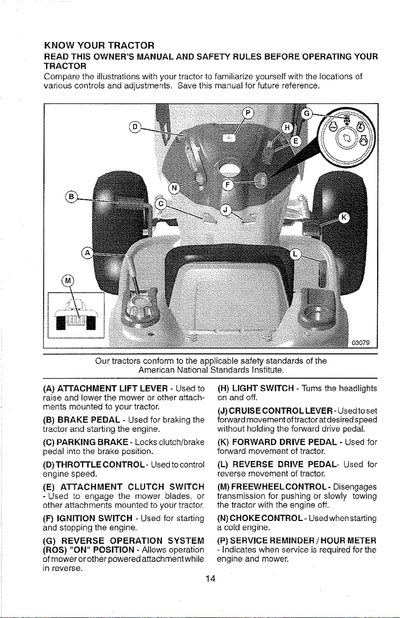
KNOW YOUR TRACTOR
READ THIS OWNER'S MANUAL AND SAFETY RULES BEFORE OPERATING YOUR
TRACTOR
Compare the illustrations with your tractor to familiarize yourself with the locations of
various controls and adjustments. Save this manual for future reference.
Our tractors conform to the applicable safety standards of the
American National Standards Institute,
(A) ATTACHMENT LIFT LEVER - Used to
raise and lower the mower or other attach-
ments mounted to your tractor.
(B) BRAKE PEDAL - Used for braking the
tractor and starting the engine,
(C) PARKING BRAKE- Locks clutch/brake
pedal into the brake position.
(D) THROTTLE CONTROL- Used to control
engine speed.
(E) ATTACHMENT CLUTCH SWITCH
-Used to engage the mower blades, or
other attachments mounted to your tractor.
(F) IGNITION SWITCH - Used for starting
and stopping the engine.
(G) REVERSE OPERATION SYSTEM
(ROS) "ON" POSITION - Allows operation
of mower or other powered attachment while
in reverse.
(H) LIGHT SWITCH - Turns the headlights
on and off.
(J) CRUISE CONTROL LEVER- Used to set
forward movement of tractor at desired speed
without holding the forward drive pedal,
(K) FORWARD DRIVE PEDAL - Used for
forward movement of tractor.
(L) REVERSE DRIVE PEDAL- Used for
reverse movement of tractor.
(M) FREEWHEELCONTROL- Disengages
transmission for pushing or slowly towing
the tractor with the engine off.
(N) CHOKE CONTROL- Used when starting
a cold engine.
(P) SERVICE REMINDER / HOUR METER
- indicates when service is required for the
engine and mower.
t4
1
The operation of any tractor can result in foreign objects thrown into |
the eyes, which can result in severe eye damage. Always wear safety I
glasses or eye shields while operating your tractor or performing any |
adjustments or repairs. We recommend standard safety glasses or a |
wide vision safety mask worn over spectacles, |
HOW TO USE YOUR TRACTOR
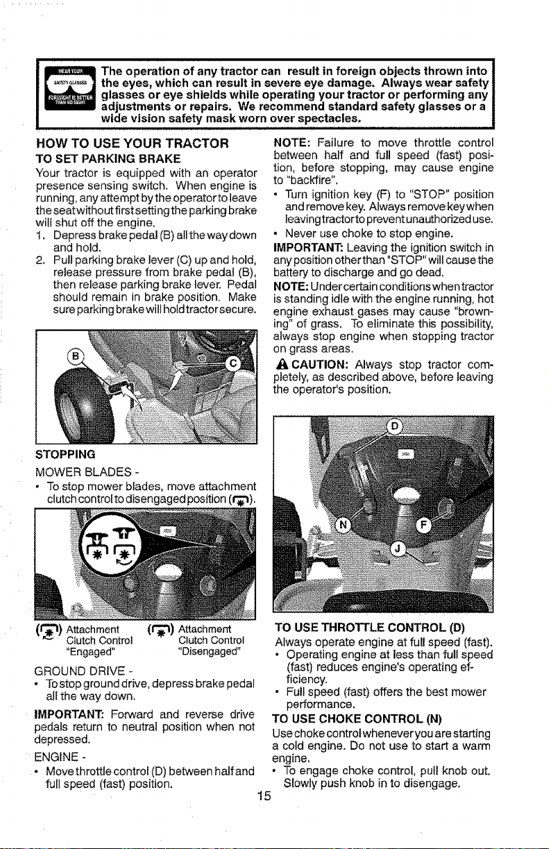
TO SET PARKING BRAKE
Your tractor is equipped with an operator
presence sensing switch. When engine is
running, any attempt by the operator to leave
the seat without first setting the parking brake
will shut off the engine.
!. Depress brake pedal (B) all the way down
and hold.
2. Pull parking brake lever (C) up and hold,
release pressure from brake pedal (B),
then release parking brake lever. Pedal
should remain in brake position. Make
sure parking brake will hold tractorsecure.
NOTE: Failure to move throttle control
between half and full speed (fast) posi-
tion, before stopping, may cause engine
to "backfire".
• Turn ignition key (F) to "STOP" position
and remove key. Always remove keywhen
leavingtractorto prevent unauthorized use.
• Never use choke to stop engine.
IMPORTANT: Leaving the ignition switch in
any position other than "STOP" will cause the
battery to discharge and go dead,
NOTE: Under certain conditions when tractor
is standing idle with the engine running, hot
engine exhaust gases may cause "brown-
ing" of grass, To eliminate this possibility,
always stop engine when stopping tractor
on grass areas.
J:I, CAUTION: Always stop tractor com-
pletely, as described above, before leaving
the operator's position.
STOPPING
MOWER BLADES -
• To stop mower blades, move attachment
clutch controtto disengaged position (l_'t),
(__) Attachment (1_) Attachment
C_utchControl ClutchControl
"Engaged.... Disengaged"
GROUND DRIVE -
* Tostopgrounddrive, depress brake pedal
nit the way down,
IMPORTANT: Forward and reverse drive
pedals return to neutral position when not
depressed.
ENGINE -
- Move throttle control (D) between half and
full speed (fast) position.
TO USE THROTTLE CONTROL (D)
Always operate engine at full speed (fast).
• Operating engine at less than full speed
(fast) reduces engine's operating ef-
ficiency.
• Full speed (fast) offers the best mower
performance.
TO USE CHOKE CONTROL (N)
Use choke control whenever you are starting
a cotd engine. Do not use to start a warm
engine.
• To engage choke control, pull knob out.
Slowly push knob in to disengage.
15
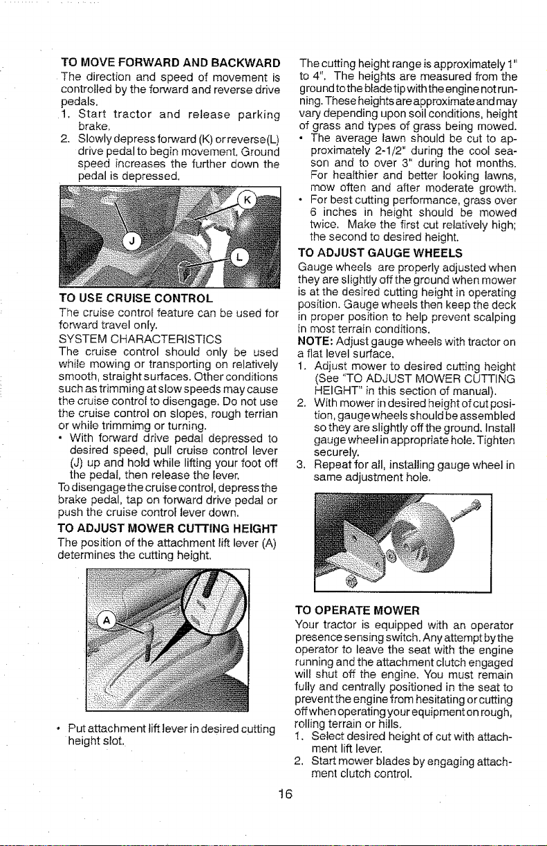
TO MOVE FORWARD AND BACKWARD
The direction and speed of movement is
controited by the forward and reverse drive
pedals.
t, Start tractor and release parking
brake,
2. Slowly depress forward (K) or reverse(L)
drive pedal to begin movement. Ground
speed increases the further down the
pedal is depressed.
TO USE CRUISE CONTROL
The cruise control feature can be used for
forward travel only.
SYSTEM CHARACTERISTICS
The cruise control should only be used
while mowing or transporting on relatively
smooth, straight surfaces. Other conditions
such as trimming at slow speeds may cause
the cruise control to disengage, Do not use
the cruise control on slopes, rough terrian
or while trimmimg or turning.
- With forward drive pedal depressed to
desired speed, pull cruise control lever
(J) up and hold while lifting your foot off
the pedal, then release the lever,
To disengagethe cruise control, depress the
brake pedal, tap on forward drive pedal or
push the cruise control lever down.
TO ADJUST MOWER CUTTING HEIGHT
The position of the attachment lift lever (A)
determines the cutting height.
The cutting height range is approximately 1"
to 4". The heights are measured from the
ground tothe blade tip with the engine not run-
ning. These heights are approximate and may
vary depending upon soil conditions, height
of grass and types of grass being mowed.
• The average lawn should be cut to ap-
proximately 2-1/2" during the cool sea-
son and to over 3" during hot months.
For healthier and better looking lawns,
mow often and after moderate growth.
• For best cutting performance, grass over
6 inches in height should be mowed
twice. Make the first cut relatively high;
the second to desired height.
TO ADJUST GAUGE WHEELS
Gauge wheels are properly adjusted when
they are slightly off the ground when mower
is at the desired cutting height in operating
position. Gauge wheels then keep the deck
in proper position to help prevent scalping
in most terrain conditions.
NOTE: Adjust gauge wheels with tractor on
a flat level surface.
1. Adjust mower to desired cutting height
(See "TO ADJUST MOWER CUTTING
HEIGHT" in this section of manual).
2. With mower in desired height of cut posi-
tion, gauge wheels should be assembled
so they are slightly off the ground. Install
gauge wheel in appropriate hole. Tighten
securely.
3. Repeat for all, installing gauge wheel in
same adjustment hole.
* Putattachmenttifttever in desired cutting
height slot,
TO OPERATE MOWER
Your tractor is equipped with an operator
presence sensing switch. Any attempt by the
operator to leave the seat with the engine
running and the attachment clutch engaged
wil! shut off the engine, You must remain
fully and centrally positioned in the seat to
prevent the engine from hesitating or cutting
offwhen operating your equipment on rough,
rolling terrain or hills.
!. Select desired height of cut with attach-
ment lift lever.
2, Start mower blades by engaging attach-
ment clutch control.
16
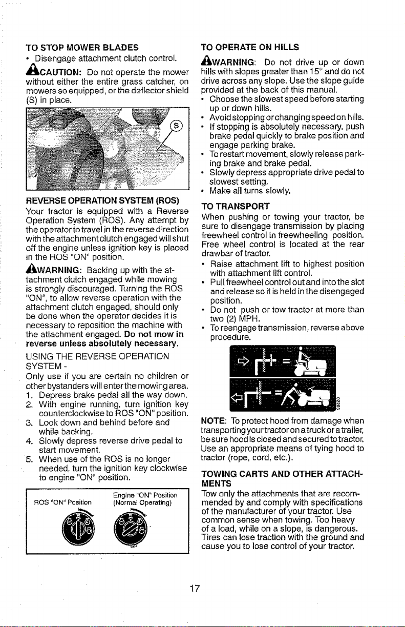
TO STOP MOWER BLADES
• Disengage attachment clutch control.
,_CAUTION: Do not operate the mower
without either the entire grass catcher, on
mowers so equipped, or the deflector shield
(S) in place.
REVERSE OPERATION SYSTEM (ROS)
"Your tractor is equipped with a Reverse
Operation System (ROS), Any attempt by
the operator to travel in the reverse direction
with the attachment clutch engaged will shut
off the engine unless ignition key is placed
in the ROS "ON" position,
_LWARNING: Backing up with the at-
tachment clutch engaged while mowing
is strongly discouraged, Turning the ROS
"ON", to allow reverse operation with the
attachment clutch engaged, should only
be done when the operator decides it is
necessary to reposition the machine with
the attachment engaged. Do not mow in
reverse unless absolutely necessary,
USING THE REVERSE OPERATION
SYSTEM -
Only use if you are certain no children or
other bystanders will enter the mowing area.
1. Depress brake pedal all the way down.
2. With engine running, turn ignition key
counterclockwise to ROS "ON" position.
3, Look down and behind before and
while backing.
4, Slowly depress reverse drive pedal to
start movement,
5. When use of the ROS is no longer
needed, turn the ignition key clockwise
to engine "ON" position.
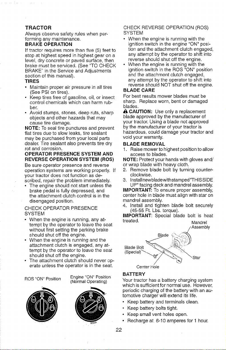
ROS "ON" Position
Engine "ON" Position
(Normal Operating)
TO OPERATE ON HILLS
_WARNING: Do not drive up or down
hills with slopes greater than 15 ° and do not
drive across any slope. Use the slope guide
provided at the back of this manual.
• Choose the slowest speed before starting
up or down hills.
• Avoid stoppingor changing speed on hills.
- If stepping is absolutely necessary, push
brake pedal quicklyto brake position and
engage parking brake.
• To restart movement, stowly retease park-
ing brake and brake pedal.
•Slowly depress appropriate drive pedal to
slowest setting,
• Make ail turns slowly,
TO TRANSPORT
When pushing or towing your tractor, be
sure to disengage transmission by placing
freewheel control in freewheeling position.
Free wheel control is located at the rear
drawbar of tractor.
• Raise attachment lift to highest position
with attachment lift control.
• Pull freewheel control out and into the slot
and release so it is held in the disengaged
position,
o Do not push or tow tractor at more than
two (2) MPH.
. To reengage transmission, reverse above
procedure.
NOTE: To protect hood from damage when
transporting your tractor on atruck or atrailer,
besure hood is closed and secured to tractor.
Use an appropriate means of tying hood to
tractor (rope. cord, etc.).
TOWING CARTS AND OTHER ATTACH-
MENTS
Tow only the attachments that are recom-
mended by and comply with specifications
of the manufacturer of your tractor. Use
common sense when towing. Too heavy
of a load, while on a slope, is dangerous.
Tires can lose traction with the ground and
cause you to lose control of your tractor.
17
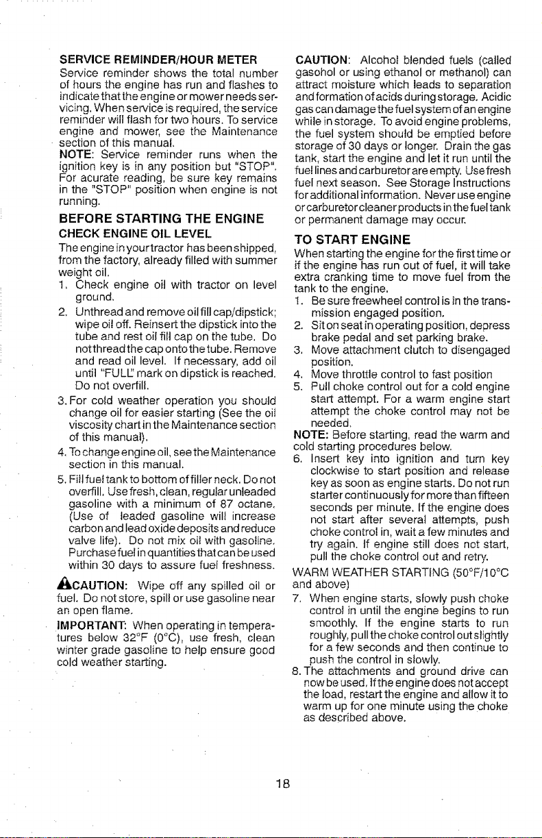
SERVICE REMINDER/HOUR METER
Service reminder shows the total number
of hours the engine has run and flashes to
indicate that the engine or mower needs ser-
vicing. When service is required, the service
reminder will flash for two hours. To service
engine and mower, see the Maintenance
section of this manual.
NOTE: Service reminder runs when the
ignition key is in any position but "STOP".
For acurate reading, be sure key remains
in the "STOP" position when engine is not
running.
BEFORE STARTING THE ENGINE
CHECK ENGINE OIL LEVEL
The engine in your tractor has been shipped,
from the factory, already filled with summer
weight oil.
1, Check engine oil with tractor on level
ground.
2. Unthread and remove oil fill cap/dipstick;
wipe oil off. Reinsert the dipstick into the
tube and rest oil fill cap on the tube, Do
notthreadthe cap ontothetube. Remove
and read oil level. If necessary, add oil
until "FULL:' mark on dipstick is reached.
Do not overfill.
3. For cofd weather operation you should
change oil for easier starting (See the oiI
viscosity" chart in the Maintenance section
of this manual).
4, To change engine oil, see the Maintenance
section in this manual.
5. Fill fuef tank to bottom of filler neck. Do not
overfill. Use fresh, clean, regular unleaded
gasoline with a minimum of 87 octane.
(Use of leaded gasoline will increase
carbon and lead oxide deposits and reduce
valve life). Do not mix oil with gasoline.
Purchase fuel in quantities that can be used
within 30 days to assure fuel freshness.
_CAUTION: Wipe off any spilled oil or
fuel. Do not store, spill or use gasoline near
an open flame.
IMPORTANT: When operating in tempera-
tures below 32°F (0°C), use fresh, clean
winter grade gasoline to help ensure good
cold weather starting.
CAUTION: Alcohol blended fuels (called
gasohol or using ethanol or methanol) can
attract moisture which leads to separation
and formation of acids during storage. Acidic
gas can damage the fuel system of an engine
while in storage. To avoid engine problems,
the fuel system should be emptied before
storage of 30 days or longer. Drain the gas
tank, start the engine and let it run until the
fuel lines and carburetor are empty, Use fresh
fuel next season. See Storage Instructions
for additional information. Never use engine
orcarburetor cleaner products in thefuel tank
or permanent damage may occur.
TO START ENGINE
When starting the engine for the first time or
if the engine has run out of fuel, it will take
extra cranking time to move fuel from the
tank to the engine,
1. Be sure freewheel control is in the trans-
mission engaged position.
2. Sit on seat in operating position, depress
brake pedal and set parking brake.
3, Move attachment clutch to disengaged
position,
4. Move throttle control to fast position
5. Putl choke control out for a cold engine
start attempt. For a warm engine start
attempt the choke control may not be
needed.
NOTE: Before starting, read the warm and
cold starting procedures below.
6. Insert key into ignition and turn key
clockwise to start position and release
key as soon as engine starts. Do not run
starter continuously for more than fifteen
seconds per minute, If the engine does
not start after several attempts, push
choke control in, wait afew minutes and
try again. If engine still does not start,
pull the choke control out and retry.
WARM WEATHER STARTING (50°F/10°C
and above)
7. When engine starts, slowly push choke
control in until the engine begins to run
smoothly, If the engine starts to run
roughly, pull the choke control out slightly
for a few seconds and then continue to
push the control in slowly.
8. The attachments and ground drive can
now be used, If the engine does not accept
the load, restart the engine and allow it to
warm up for one minute using the choke
as described above.
18
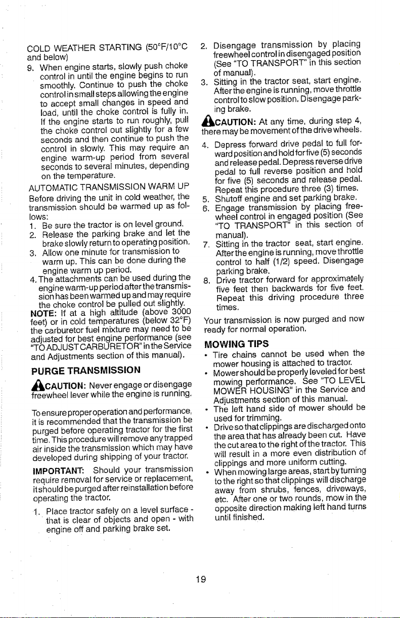
COLD WEATHER STARTING (50°Fil0°C
and below)
9. When engine starts, slowly push choke
control in until the engine begins to run
smoothly. Continue to push the choke
control in small steps allowing the engine
to accept small changes in speed and
load, until the choke control is fully in.
If the engine starts to run roughly, pull
the choke control out slightly for a few
seconds and then continue to push the
control in slowly. This may require an
engine warm-up period from several
seconds to several minutes, depending
on the temperature.
AUTOMATIC TRANSMISSION WARM UP
Before driving the unit in cold weather, the
transmission should be warmed up as fol-
lows:
1. Be sure the tractor is on level ground.
2. Release the parking brake and let the
brake slowly return to operating position.
3, Allow one minute for transmission to
warm up. This can be done during the
engine warm up period.
4. The attachments can be used during the
engine warm-up period after the transmis-
sion has been warmed up and may require
the choke control be pulled out slightly.
NOTE: If at a high altitude (above 3000
feet) or in cold temperatures (below 32°F)
the carburetor fuel mixture may need to be
adjusted for best engine performance lsee
"TO ADJUST CARBURETOR" in the Service
and Adjustments section of this manual).
PURGE TRANSMISSION
_IbCAUTION: Never engage or disengage
freewheel lever while the engine is running.
To ensure proper operation and performance,
it is recommended that the transmission be
purged before operating tractor for the first
time, This procedure will remove anytrapped
air inside the transmission which may have
developed during shipping of your tractor.
IMPORTANT: Should your transmission
require removal for service or replacement,
it should be purged after reinstatlation before
operating the tractor.
1. Place tractor safely on a level surface -
that is clear of objects and open - with
engine off and parking brake set.
2, Disengage transmission by placing
freewheel control in disengaged position
(See "TO TRANSPORT" in this section
of manual),
3. Sitting in the tractor seat, start engine,
After the engine is running, move throttle
control to stow position, Disengage park-
ing brake,
_CAUTION: At any time, during step 4,
there may be movement ofthe drive wheels.
4. Depress forward drive pedal to full for-
ward position and hold for five (5) seconds
and release pedal. Depress reverse drive
pedal to full reverse position and hold
for five _5) seconds and release pedal.
Repeat this procedure three (3) times,
5. Shutoff engine and set parking brake,
6. Engage transmission by placing free-
wheel control in engaged position (See
"TO TRANSPORT" in this section of
manual).
7, Sitting in the tractor seat, start engine,
After the engine is running, move throttle
control to half (1/2) speed, Disengage
parking brake.
8. Drive tractor forward for approximately
five feet then backwards for five feet.
Repeat this driving procedure three
times,
'four transmission is now purged and now
ready for normal operation,
MOWING TIPS
. Tire chains cannot be used when the
mower housing is attached to tractor.
• Mower should be properly leveled for best
mowing performance. See "TO LEVEL
MOWER HOUSING" in the Service and
Adjustments section of this manual.
• The left hand side of mower should be
used for trimming.
• Drive so that clippings are discharged onto
the area that has already been cut. Have
the cut area to the right of the tractor, This
wilt result in a more even distribution of
clippings and more uniform cutting.
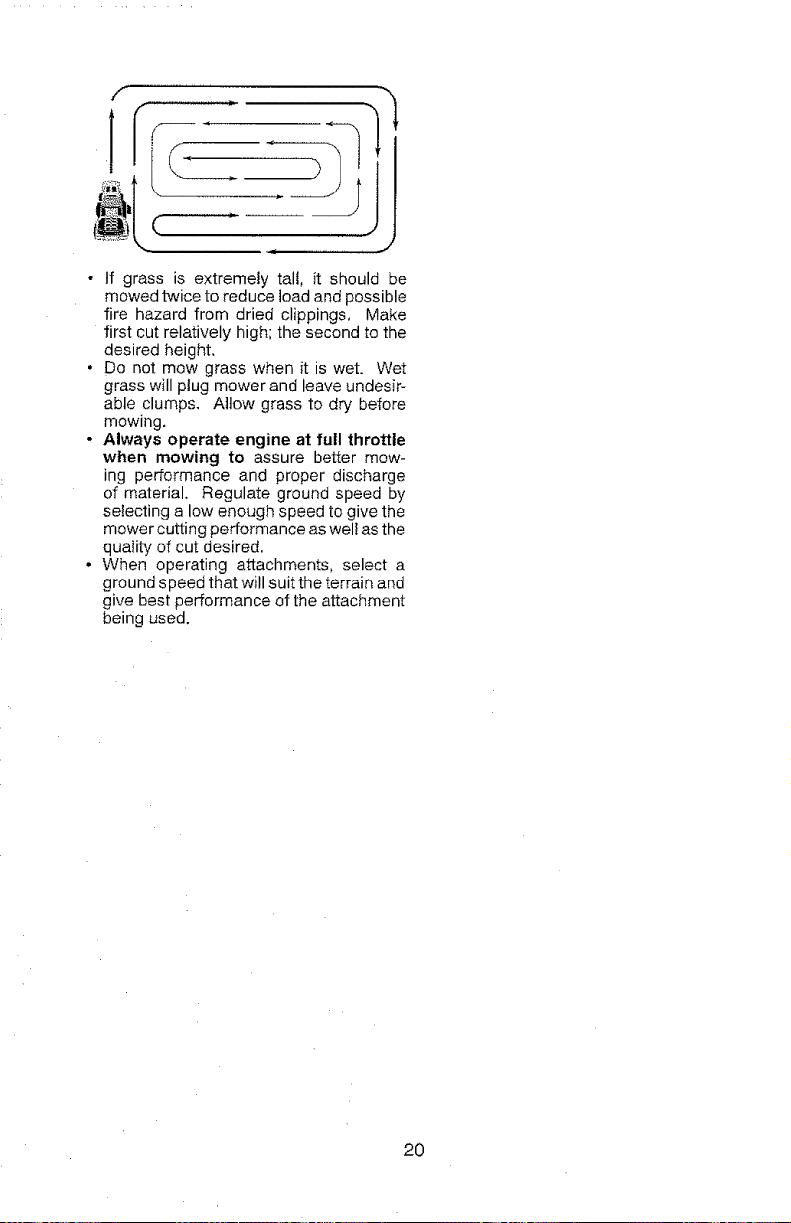
• When mowing large areas, start by turning
to the right so that clippings will discharge
away from shrubs, fences, driveways,
etc. After one or two rounds, mow in the
opposite direction making left hand turns
until finished.
t9
I
• If grass is extremely tall, it should be
mowed twice to reduce load and possible
fire hazard from dried clippings, Make
first cut relatively high; the second to the
desired height,
• Do not mow grass when it is wet. Wet
grass will ptug mower and leave undesir-
able clumps, Allow grass to dry before
mowing,
- Always operate engine at full throttle
when mowing to assure better mow-
ing performance and proper discharge
of material, Regulate ground speed by
selecting a low enough speed to give the
mower cutting performance as wel! as the
quality of cut desired.
• When operating attachments, select a
ground speed that will suit the terrain and
give best performance of the attachment
being used,
20
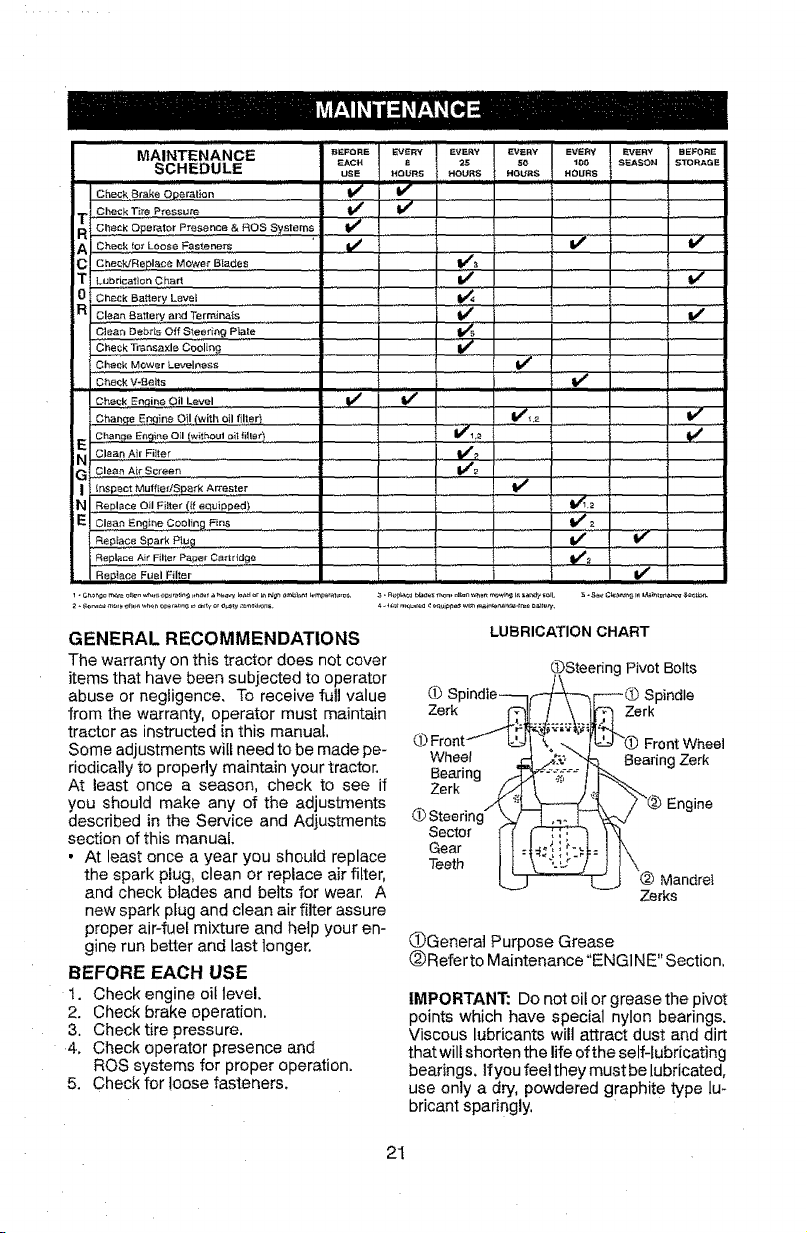
MAINTENANCE B_FOR_ EVERY EWHV _VEHY EVERY e_EHY SEFO_E
SCHEDULE EAC. _ 25 so lee SEASOH STORAGE
USE HOURS HOURS HOURS HOURS
I i,, ,, I I I i,i I n l i,, I,
Check Brake Operation _ _"
Check Ti_*e Pressure
_ Check Operotor Presence & ROE
Systems v'
A Chook to_ Loose Fastener_ .......' I v v v
C Che_WRepleee Mowe_" B_ades = _
T LubricationChart _
0 Check ea.e;y Levee
R Cleon Battery and Termina{s
C!eae Debris Off Stee_'ing P_ate _ .... .......
Che£k Tr6nsaxlB Cooling I_
Ohe_kMowerLevelness .... If
Check V-Belts
Check E_i.e Oil Level _
Chae_e En# ne O I (with o fller) V_ _ ......
ChaRge Eegit_e Oil [withoul oit filler} _#fl,_
N_ Clean Air Fi]_er I_
G '9!ean Ai_ Screen _
! _nsPeet,,M,_,t,ffEf_SP°rkA_e_,_................ "V'
v%'
iN Replace Oil Fiiter (_ equiPPed! ..................
E Clean Engine Cooling Fins 11## 2
Replace Spark P!u 9
........................
_
........
_
11
Replace Air Filter Pape_ Cartridge : : !1_
R ep]a£e,,,,,Fuel, ,Filter ....... if,,
GENERAL RECOMMENDATIONS
The warranty on this tractor does not cover
items that have been subjected to operator
abuse or negligence. To receive full value
from the warranty, operator must maintain
tractor as instructed in this manual,
Some adjustments will need to be made pe-
riodically to properly maintain your tractor.
At least once a season, check to see if
you should make any of the adjustments
described in the Service and Adjustments
section of this manual.
• At least once a year you should replace
the spark plug, clean or replace air filter,
and check blades and belts for wear, A
new spark plug and clean air filter assure
proper air-fuel mixture and help your en-
gine run better and last longer.
BEFORE EACH USE
t. Check engine oil level.
2. Check brake operation.
3. Check tire pressure.
4. Check operator presence and
ROS systems for proper operation.
5. Check for loose fasteners.
LUBRICATION CHART
Cb
Zerk
WheeI
Bearing
Zerk
Sector
Gear
Teeth
_Steering Pivot Bolts
Front Wheel
Bearing Zerk
tlne
Mandrel
Zerks
QGenera] Purpose Grease
@Refer to Maintenance"ENG1NE" Section,
IMPORTANT: Do not oif or grease the pivot
points which have special nylon bearings.
Viscous lubricants wilt attract dust and dirt
that will shorten the life of the self-lubricating
bearings. Ifyou feel they must be lubricated,
use only a dry, powdered graphite type lu-
bricant sparingly,
21
TRACTOR
Always observe safety rules when per-
forming any maintenance,
BRAKE OPERATION
If tractor requires more than five (5) feet to
stop at highest speed in highest gear on a
level, dry concrete or paved surface, then
brake must be serviced. (See "TO CHECK
BRAKE" in the Service and Adjustments
section of this manual).
TIRES
• Maintain proper air pressure in all tires
(See PSI on tires),
• Keep tires free of gasoline, oil, or insect
control chemicals which can harm rub-
ber.
• Avoid stumps, stones, deep ruts, sharp
objects and other hazards that may
cause tire damage.
NOTE: To seal tire punctures and prevent
ftat tires due to slow leaks, tire sealant
may be purchased from your local parts
dealer, Tire sealant also prevents tire dry
rot and corrosion.
OPERATOR PRESENCE SYSTEM AND
REVERSE OPERATION SYSTEM (ROS)
Be sure operator presence and reverse
operation systems are working properly, tf
your tractor does not function as de-
scribed, repair the problem immediately,
• The engine should not start unless the
brake pedal is fully depressed, and
the attachment clutch control is in the
disengaged position.
CHECK OPERATOR PRESENCE
SYSTEM
• When the engine is running, any at-
tempt by the operator to leave the seat
without first setting the parking brake
should shut off the engine.
• When the engine is running and the
attachment clutch is engaged, any at-
tempt by the operator to leave the seat
should shut off the engine.
• The attachment clutch should never op-
erate unless the operator is in the seat,
ROS "ON" Position Engine "ON" Position
(Normal Operating)
CHECK REVERSE OPERATION (ROS)
SYSTEM
• When the engine is running with the
ignition switch in the engine "ON" posi-
tion and the attachment clutch engaged,
any attempt by the operator to shift into
reverse should shut off the engine,
• When the engine is running with the
ignition switch in the ROS "ON" position
and the attachment clutch engaged,
any attempt by the operator to shift into
reverse should NOT shut off the engine.
BLADE CARE
For best results mower blades must be
sharp. Replace worn, bent or damaged
blades.
& CAUTION: Use only a replacement
btade approved by the manufacturer of
your tractor, Using a blade not approved
by the manufacturer of your tractor is
hazardous, could damage your tractor and
void your warranty.
BLADE REMOVAL
1. Raise mower to highest position to allow
access to blades.
NOTE: Protect your hands with gloves and/
or wrap blade with heavy cloth,
2. Remove blade bolt by turning counter-
clockwise.
3. Installnewbladewithstamped"THISSlDE
UP" facing deck and mandrel assembly.
IMPORTANT: To ensure proper assembly,
center hole in blade must align with star on
mandrel assembly,
4. Install and tighten blade bott securely
(45-55 Ft, Lbs. torque),
IMPORTANT: Special blade bolt is heat
treated. Mandrel
_j Assembly
Blade _[_"--.4:_.-__-,
(Special)"'--.___.._.
Center Hole
BATTERY
Your tractor has a battery charging system
which is sufficient for normal use. However,
periodic charging of the battery with an au-
tomotive charger witl extend its life.
• Keep battery and terminals clean,
• Keep battery bolts tight,
• Keep small vent holes open.
• Recharge at 6-t0 amperes for ! hour.
22
NOTE: The original equipment batten# on
your tractor is maintenance free. Do not
attempt to open or remove caps or covers.
Adding or checking level of electrolyte is
not necessary.
TO CLEAN BA-i-i-ERY AND TERMINALS
Corrosion and dirt on the battery and termi-
nals can cause the battery to "leak" power.
1. Remove terminal guard.
2. Disconnect BLACK battery cable first
then RED battery cable and remove
battery from tractor.
3. Rinsethebatterywithplainwateranddry.
4. Clean terminals and battery cable ends
with wire brush until bright.
5. Coat terminals with grease or petroleum
jelly.
6. Reinstall battery (See "REPLACING
BATTERY" in the SERVICE AND AD-
JUSTMENTS section of this manual).
TRANSAXLE MAINTENANCE
The transmission fan and cooling fins should
be kept clean to assure proper cooling. Do
not attemptto clean fan or transmission while
engine is running or while the transmission
is hot. To prevent possible damage to seals,
do not use high pressure water or steam to
clean transaxle.
• Inspect cooling fan to be sure fan blades
are intact and clean.
• Inspect cooling fins for dirt, grass clippings
and other materials. To prevent damage to
seals, do not use compressed air or high
pressure sprayer to clean cooling fins.
TRANSAXLE PUMP FLUID
The transaxle was sealed at the factory and
fluid maintenance is not required for the life
of the transaxie. Should the transaxle ever
leak or require servicing, contact your near-
est Sears or other qualified service center.
V-BELTS
CheckV-betts for deterioration and wear after
100 hours of operation and replace if neces-
sary. The belts are not adjustable. Replace
belts if they begin to slip from wear.
ENGINE
LUBRICATION
Only use high quality detergent oit rated
with API service classification SG-SL.
Select the oil's SAE viscosity grade
according to your expected operating
temperature.
23
Change the oil after every 50 hours of op-
eration or at least once a year if the tractor
is not used for 50 hours in one year.
Check the crankcase oil level before start-
ing the engine and after each eight (8)
hours of operation.
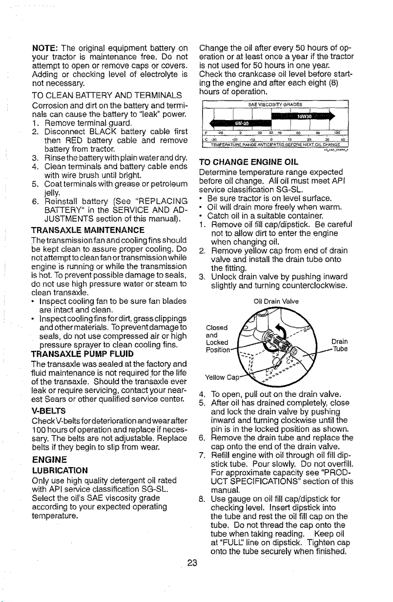
TO CHANGE ENGINE OIL
Determine temperature range expected
before oil change. All oil must meet API
service classification SG-SL.
, Be sure tractor is on level surface.
• Oil will drain more freely when warm.
• Catch oil in a suitable container.
1. Remove oil fill cap/dipstick. Be careful
not to allow dirt to enter the engine
when changing oil.
2. Remove yellow cap from end of drain
valve and install the drain tube onto
the fitting.
3. Unlock drain valve by pushing inward
slightly and turning counterclockwise.
Oil Drain Vaive
Yellow Cap
4, TO open. putf out on the drain valve.
5, After oil has drained completely, close
and lock the drain valve by pushing
inward and turning clockwise until the
pin is in the locked position as shown.
6. Remove the drain tube and replace the
cap onto the end of the drain valve.
7, Refill engine with oil through oil fill dip-
stick tube. Pour slowly. Do not overfill.
For approximate capacity see "P ROD-
UCT SPECIFICATIONS" section of this
manual.
8, Use gauge on oil fill cap/dipstick for
checking level. Insert dipstick into
the tube and rest the oil fill cap on the
tube, Do not thread the cap onto the
tube when taking reading, Keep oil
at "FULl/' line on dipstick. Tighten cap
onto the tube securely when finished.
ENGINEOILFILTER
Replacetheengineoilfiltereveryseasonor
everyotheroilchangeifthetractorisused
morethan100hoursinoneyear.
AIRFILTER
Yourenginewil!notrunproperlyusinga
dirtyairfilter,Servicepapercartridgeevery
twomonthsorevery25hoursofoperation,
whicheveroccursfirst.
Servicepapercartridgemoreoftenunder
dustyconditions.
Replacethepapercartridgeannually,orafter
every100hoursofoperation,
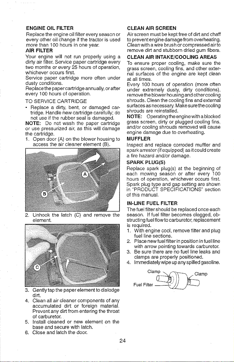
TOSERVICECARTRIDGE
• Replaceadirty,bent,ordamagedcar-
tridge,Handlenewcartridgecarefully;do
notuseiftherubbersealisdamaged.
NOTE:Donotwashthepapercartridge
orusepressurizedair,asthiswilldamage
thecartridge.
t, Opendoor(A)ontheblowerhousingto
accesstheaircleanerelement(B).
2. Unhookthelatch(C)andremovethe
element.
3. Gentlytapthepaperelementtodislodge
dirt.
4. Cleanallaircleanercomponentsofany
accumulateddirtorforeignmaterial.
Preventanydirtfromenteringthethroat
ofcarburetor.
5, Installcleanedornewelementonthe
baseandsecurewithlatch,
6. Closeandlatchthedoor.
24
CLEAN AIR SCREEN
Air screen must be kept free of dirt and chaff
to prevent engine damage from overheating.
Clean with awire brush or compressed airto
remove dirt and stubborn dried gum fibers,
CLEAN AIR INTAKE/COOLING AREAS
To ensure proper cooling, make sure the
grass screen, cooling fins, and other exter-
nal surfaces of the engine are kept clean
at all times.
Every 100 hours of operation (more often
under extremely dusty, dirty conditions),
remove the blower housing and other cooIing
shrouds, Clean the cooling fins and external
surfaces as necessary. Make surethe cooling
shrouds are reinstalled.
NOTE: Operatingthe engine with a blocked
grass screen, dirty or plugged cooling fins,
and/or coo_ing shrouds removed will cause
engine damage due to overheating.
MUFFLER
_nspect and replace corroded muffter and
spark arrester (if equipped) as it could create
a fire hazard and/or damage.
SPARK PLUG(S)
Replace spark plug(s) at the beginning of
each mowing season or after every 100
hours of operation, whichever occurs first.
Spark plug type and gap setting are shown
in "PRODUCT SPECIFICATIONS" section
of this manual.
IN-LINE FUEL FILTER
The fuel filter should be replaced once each
season, if fuel filter becomes clogged, ob-
structing fuel flowto carburetor, replacement
is required.
1. With engine cool, remove filter and plug
fuel _ine sections,
2. Place new fuel filter in position in fuel line
with arrow pointing towards carburetor.
3. Be sure there are no fuel line leaks and
clamps are properly positioned.
4. lmmediatelywipe up any spilled gasoline,
Fuel Filter
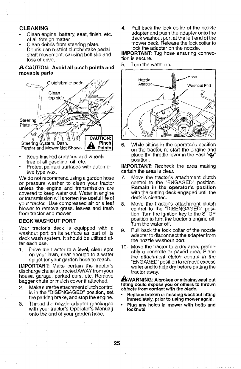
CLEANING
, Clean engine, battery, seat, finish, etc.
of all foreign matter.
• Clean debris from steering plate.
Debris can restrict clutch/brake pedat
shaft movement, causing belt slip and
loss of drive.
,O_CAUTION: Avoid all pinch points and
movable parts
Clutch/brake pedal
_i Clean
top side
Steer!no
CAUTION:
S{eering System, Dash, _ Pinch
Fender and Mower i_ot Shown _ Points
- Keep finished surfaces and wheels
free of all gasoline, oil, etc.
Protect painted surfaces with automo-
tive type wax.
We do not recommend using a garden hose
or pressure washer to clean your tractor
unless the engine and transmission are
covered to keep water out. Water in engine
or transmission will shorten the useful life of
your tractor. Use compressed air or a leaf
blower to remove grass, leaves and trash
from tractor and mower,
DECK WASHOUT PORT
Your tractor's deck is equipped with a
washout port on its surface as part of its
deck wash system, it should be utilized af-
ter each use.
t. Drive the tractor to a level, clear spot
on your lawn, near enough to a water
spigot for your garden hose to reach.
IMPORTANT: Make certain the tractor's
discharge chute is directed AWAY from your
house, garage, parked cars, etc. Remove
bagger chute or mulch cover if attached.
2. Make surethe attachment clutch controt
is in the "DISENGAGED" position, set
the parking brake, and stop the engine.
3. Thread the nozzle adapter (packaged
with your tractor s Operator's Manual)
onto the end of your garden hose,
4. Pull back the lock collar of the nozzle
adapter and push the adapter onto the
deck washout port at the left end of the
mower deck. Release the lock collar to
lock the adapter on the nozzle.
IMPORTAN_ Tug hose ensuring connec-
tion is secure,
5. Turn the water on.
Nozzle
Washout Port
6, While sitting in the operator's position
on the tractor, re-start the engine and
place the throttle lever in the Fast ",_"
position.
IMPORTANT: Recheck the area making
certain the area is clear,
7, Move the tractor's attachment clutch
control to the "ENGAGED" position.
Remain in the operator's position
with the cutting deck engaged until the
deck is cleaned,
8, Move the tractor's attachment clutch
control to the "DISENGAGED" posi-
tion. Turn the ignition key to the STOP
position to turn the tractor's engine off.
Turn the water off.
9, Pul! back the lock collar of the nozzle
adapter to disconnect the adapter from
the nozzle washout port.
10. Move the tractor to a dry area, prefer-
ably a concrete or paved area, Place
the attachment clutch control in the
"ENGAGED" position to remove excess
water and to hetp dry before putting the
tractor away.
_WARNING: A broken or missing washout
fitting could expose you or others to thrown
objects from contact with the blade,
• Replace broken or missing washout fitting
immediately, prior to using mower again.
• Plug any holes in mower with bolts and
iooknuts,
25
_ ARNING: TO AVOID SERIOUS INJURY, BEFORE PERFORMING ANY SERVICE OR
ADJUSTMENTS:
1. Depress clutch/brake pedal fully and set parking brake.
3. Place attachment clutch in "DISENGAGED" position.
4. Turn ignition key to "STOP" and remove key.
5. Make sure the blades and all moving parts have completely stopped.
6. Disconnect spark plug wire from spark plug and place wire where it cannot come
in contact with plug.
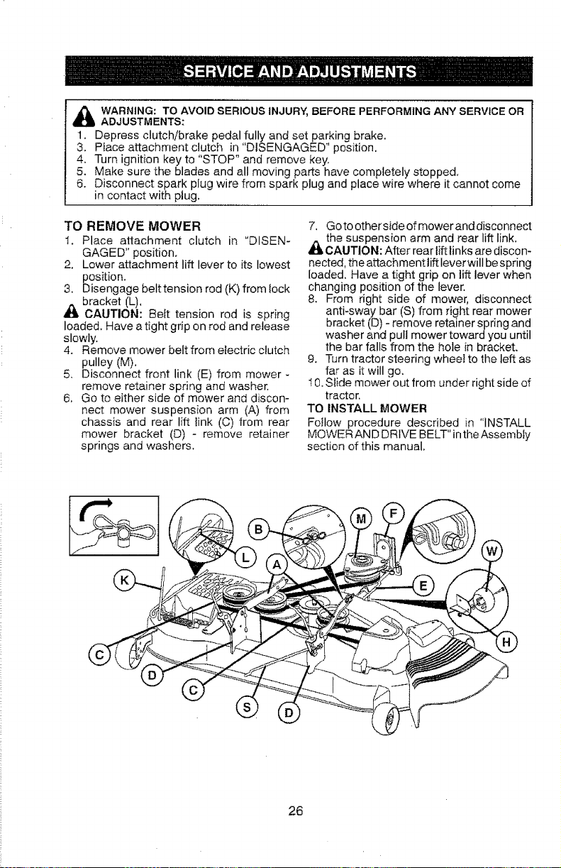
TO REMOVE MOWER
t. Place attachment clutch in "DISEN-
GAGED" position.
2. Lower attachment lift lever to its lowest
position.
3. Disengage belttension rod (K) from lock
bracket (L),
CAUTION: Bett tension rod is spring
loaded, Have a tight grip on rod and release
slowly.
4. Remove mower belt from electric clutch
pulley (M),
5, Disconnect front link (E) from mower -
remove retainer spring and washer,
6, Go to either side of mower and discon-
nect mower suspension arm (A) from
chassis and rear lift tink (C) from rear
mower bracket (D) - remove retainer
springs and washers.
7. Go to otherside of mower and disconnect
_the suspension arm and rear lift link,
CAUTION: After rear lift links are discon-
nected, the attachment lift leverwill be spring
loaded. Have a tight grip on lift lever when
changing position of the lever.
8. From right side of mower, disconnect
anti-sway bar (S) from right rear mower
bracket (D) - remove retainer spring and
washer and pull mower toward you until
the bar falls from the hole in bracket.
9. Turn tractor steering whee! to the left as
far as it will go.
I 0. Slide mower out from under right side of
tractor.
TO INSTALL MOWER
FoIlow procedure described in "INSTALL
MOWER AN D DRIVE BELT" in the Assembty
section of this manual,
26
TO LEVEL MOWER
Make sure tires are properly inflated to the
PSl shown on tires. If tires are over or under
inflated, it may affect the appearance of your
lawn and Iead you to think the mower is not
adjusted properly.
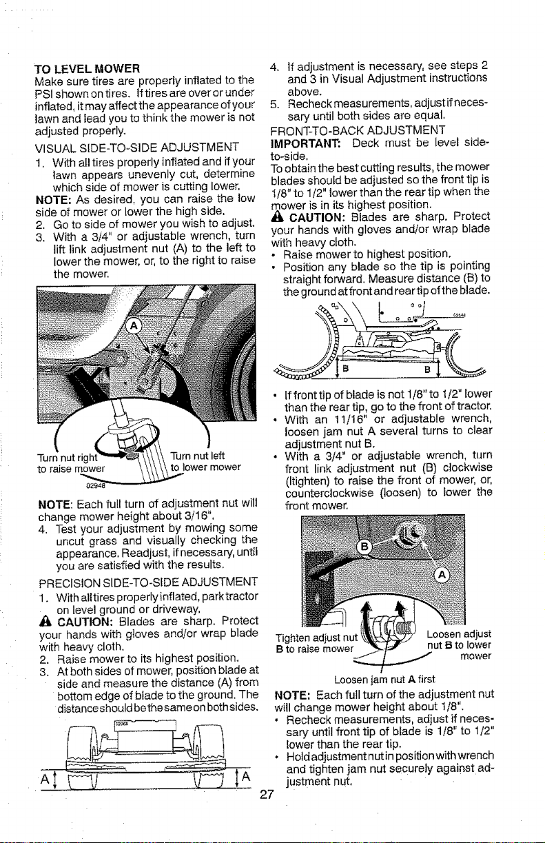
VISUAL SIDE-TQ-SIDE ADJUSTMENT
1, With ail tires properly inflated and if your
lawn appears unevenly cut, determine
which side of mower is cutting lower,
NOTE: As desired, you can raise the low
side of mower or lower the high side.
2. Go to side of mower you wish to adjust.
3, With a 3/4" or adjustable wrench, turn
lift link adjustment nut (A) to the left to
lower the mower, or, to the right to raise
the mower,
Turn nut righl Turn nut left
to raise mower to lower mower
NOTE: Each full turn of adjustment nut wilt
change mower height about 3/16",
4. Test your adjustment by mowing some
uncut grass and visually checking the
appearance, Readjust, if necessary, until
you are satisfied with the results.
PRECISION SlDE-TQ-SfDE ADJUSTMENT
1. With aUtires properly inflated, park tractor
on level ground or driveway,
CAUTION: Blades are sharp, Protect
your hands with gloves and/or wrap blade
with heavy cloth,
2. Raise mower to its highest position.
3. At both sides of mower, position blade at
side and measure the distance (A) from
bottom edge of blade to the ground. The
distanceshould bethesame on bothsides.
4. If adjustment is necessary, see steps 2
and 3 in Visual Adjustment instructions
above.
5. Recheck measurements, adjust if neces-
sary until both sides are equal.
FRONT-TO-BACK ADJUSTMENT
IMPORTANT: Deck must be level side-
to-side,
To obtain the best cutting results, the mower
blades should be adjusted so the front tip is
1/8" to 1/2" lower than the rear tip when the
mower is in its highest position.
CAUTION: Blades are sharp. Protect
your hands with gloves and/or wrap blade
with heavy cloth.
, Raise mower to highest position.
• Position any blade so the tip is pointing
straight forward. Measure distance (B) to
the ground at front and rear tip of the blade.
• tf front tip of blade is not 1/8" to 1/2" bower
than the rear tip, go to the front of tractor,
• With an 11/16" or adjustable wrench,
loosen jam nut A several turns to clear
adjustment nut B.
, With a 3/4" or adjustable wrench, turn
front link adjustment nut ('t3) clockwise
(Itighten) to raise the front of mower, or,
counterclockwise (loosen) to lower the
front mower.
Tighten adiust nut Loosen adjust
B to raise mower nut B to lower
mower
Loosen iam nut A first
NOTE: Each full turn of the adjustment nut
wi!l change mower height about t/8",
• Recheck measurements, adjust if neces-
sary until front tip of blade is t/8" to 1/2"
lower than the rear tip,
• Hold adjustment nut in position with wrench
and tighten jam nut securely against ad-
justment nut,
27
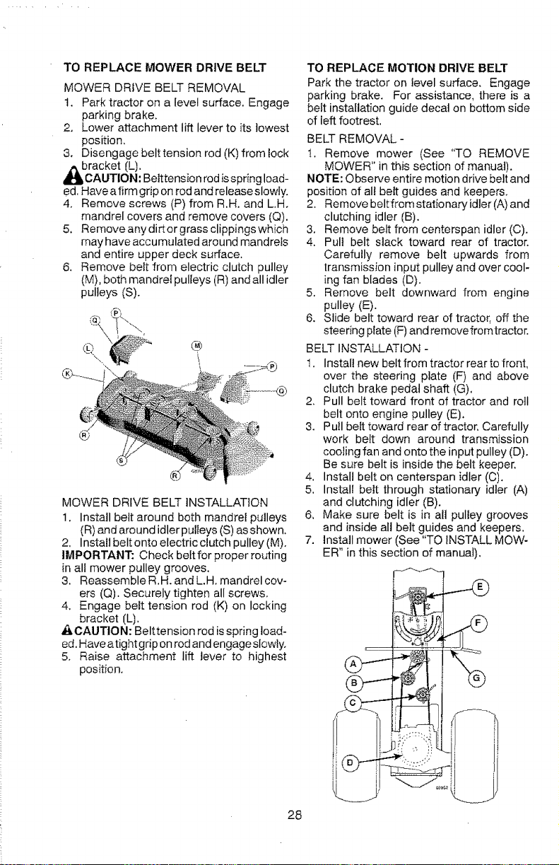
TO REPLACE MOWER DRIVE BELT
MOWER DRIVE BELT REMOVAL
t. Park tractor on a level surface. Engage
parking brake.
2. Lower attachment lift lever to its lowest
position.
3. Disengage belttension rod (K) from lock
bracket (L).
AUTION: Belt tension rod is spring load-
ed, Have a firm grip on rod and release slowly.
4, Remove screws (P) from R,H. and L,H.
mandrel covers and remove covers (Q).
5. Removeanydirtorgrass clippingswhich
may have accumulated around mandrels
and entire upper deck surface.
6. Remove belt from electric clutch pulley
(M), both mandrel pulleys (R) and all idler
pulleys (S).
®
MOWER DRIVE BELT INSTALLATION
1. Install belt around both mandrel pulleys
(R) and around idler pulleys (S) as shown,
2, Install beltonto electric clutch pulley (M).
IMPORTANT: Check beft for proper routing
in all mower pulley grooves.
3. Reassemble R.H. and L.H, mandrel cov-
ers (Q). Securely tighten all screws,
4, Engage belt tension rod (K) on locking
bracket (L).
A CAUTtON: Belttension rod is spring load-
ed. Have atight grip on rod and engage slowty.
5. Raise attachment lift lever to highest
position.
TO REPLACE MOTION DRIVE BELT
Park the tractor on level surface, Engage
parking brake. For assistance, there is a
belt installation guide decal on bottom side
of left footrest.
BELT REMOVAL-
t. Remove mower (See *'TO REMOVE
MOWER" in this section of manual).
NOTE: Observe entire motion drive belt and
position of alt belt guides and keepers,
2, Remove belt from stationary idler (A) and
clutching idler (B).
3. Remove belt from centerspan idler (C).
4. Pull belt slack toward rear of tractor.
Carefully remove belt upwards from
transmission input pulley and over cool-
ing fan blades (D).
5. Remove belt downward from engine
pulley (E).
6. Slide belt toward rear of tractor, off the
steering plate (F) and remove fromtractor.
BELT INSTALLATION -
1. Install new belt from tractor rear to front,
over the steering plate (F) and above
clutch brake pedal shaft (G),
2. Pull belt toward front of tractor and roll
belt onto engine pulley (E).
3. Pull beit toward rear of tractor, Carefully
work belt down around transmission
cooling fan and onto the input pulley (D).
Be sure belt is inside the belt keeper,
4. Install belt on centerspan idler (C).
5. Install belt through stationary idler (A)
and clutching idler (B).
6, Make sure belt is in all pulley grooves
and inside all belt guides and keepers.
7. Install mower (See "TO INSTALL MOW-
ER" in this section of manual),
28
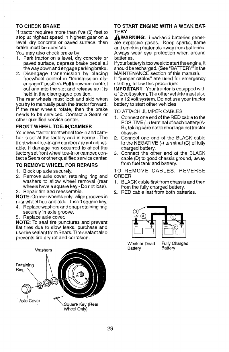
TO CHECK BRAKE
If tractor requires more than five (5) feet to
stop at highest speed in highest gear on a
level, dry concrete or paved surface, then
brake must be serviced.
You may also check brake by:
1, Park tractor on a level, dry concrete or
paved surface, depress brake pedal all
the way down and engage parking brake.
2. Disengage transmission by placing
freewheel control in "transmission dis-
engaged" position, Pull freewheel control
out and into the slot and release so it is
held in the disengaged position.
The rear wheels must lock and skid when
you try to manually push the tractor forward.
If the rear wheels rotate, then the brake
needs to be serviced. Contact a Sears or
other qualified service center.
FRONT WHEEL TOE-IN/CAMBER
Your newtractor front wheel toe-in and cam-
ber is set at the factory and is normal. The
front wheel toe-in and camber are not adjust-
able. If damage has occurred to affect the
factory set front wheel toe-in or camber, con-
tact a Sears or other qualified service center.
TO REMOVE WHEEL FOR REPAIRS
1, Block up axle securely.
2, Remove axle cover, retaining ring and
washers to allow wheel removal (rear
wheels have a square key - Do not lose).
3, Repair tire and reassemble,
NOTE: On rear wheels only: align grooves in
rear wheet hub and axle. Insert square key.
4, Replacewashers and snap retaining ring
securely in axle groove.
5. Replace axle cover.
NOTE: To seal tire punctures and prevent
flat tires due to slow leaks, purchase and
usetire sealant from Sears. Tire sealant also
prevents tire dry rot and corrosion,
washers
TO START ENGINE WITH A WEAK BAT-
TERY
_ISWARNING: Lead-acid batteries gener-
ate explosive gases. Keep sparks, flame
and smoking materials away from batteries.
Always wear eye protection when around
batteries.
If your battery istoo weakto start the engine, it
should be recharged. (See "BATTERY" inthe
MAINTENANCE section of this manual).
If "jumper cables" are used for emergency
starting, follow this procedure:
IMPORTANT: Your tractor is equipped with
a 12volt system. The othervehicle must also
be a 12 volt system. Do not use your tractor
battery to start other vehicles,
TO ATTACH JUMPER CABLES
I. Connect one end efthe RED cabtetothe
POSITIVE (+) terminal of each battery(A-
B), taking care notto short against tractor
chassis.
2. Connect one end of the BLACK cable
to the NEGATIVE (-) terminal (C) of fully
charged battery.
3, Connect the other end of the BLACK
cable (D) to good chassis ground, away
from fuel tank and battery.
TO REMOVE CABLES, REVERSE
ORDER
1. BLACKcablefirstfromchassis andthen
from the fully charged battery.
2. RED cable last from both batteries.
Weak or Dead Fully Charged
Battery Battery
Retaining
Ring
Axle Cover
'_Square Key (Rear
Wheel Only)
29
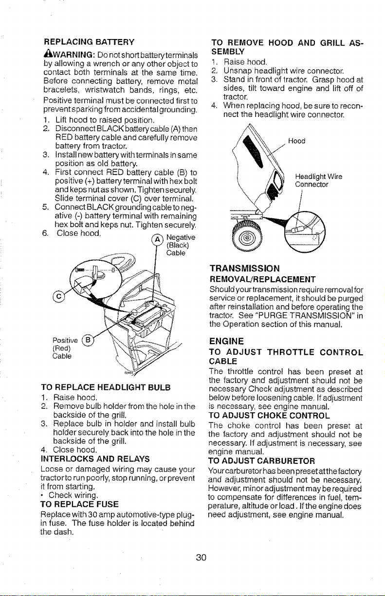
REPLACING BATTERY
,_kWARNING: Do notshort batteryterminals
by allowing a wrench or any other object to
contact both terminals at the same time.
Before connecting battery, remove metal
bracelets, wristwatch bands, rings, etc.
Positive terminal must be connected first to
preventsparking from accidental grounding.
1. Lift hood to raised position.
2. Disconnect BLACK battery cable (A) then
RED battery cable and carefully remove
battery from tractor.
3. Install new battery with terminals in same
position as old battery.
4. First connect RED battery cable (B) to
positive (+) batten/terminal with hex bolt
and keps nutas shown. Tighten securely.
Slide terminal cover (C) over terminal.
5, Connect BLACK grounding cabteto neg-
ative (-) battery terminal with remaining
hex bolt and keps nut. Tighten securely.
6. Close hood.
(_ Negative
(Black)
f Cable
Positive
(Red)
Cable
TO REPLACE HEADLIGHT BULB
1. Raise hood,
2, Remove bulb hotder from the hole inthe
backside of the grill
3. Replace bulb in holder and install bulb
holder securely back into the hole in the
backside of the grill.
4. Close hood.
INTERLOCKS AND RELAYS
Loose or damaged wiring may cause your
tractor to run poorly, stop running, or prevent
it from starting.
• Check wiring.
TO REPLACE FUSE
Replace with 30 amp automotive-type plug-
in fuse. The fuse holder is located behind
the dash.
TO REMOVE HOOD AND GRILL AS-
SEMBLY
t. Raise hood.
2. Unsnap headlight wire connector.
3. Stand in front of tractor. Grasp hood at
sides, tilt toward engine and lift off of
tractor.
4. When replacing hood, be sure to recon-
nect the headlight wire connector,
I Hood
Headlight Wire
Connector
TRANSMISSION
REMOVAL/REPLACEMENT
Should yourtransmission require removal for
service or replacement, it should be purged
after reinstaltation and before operating the
tractor, See "PURGE TRANSMISSION" in
the Operation section of this manual,
ENGINE
TO ADJUST THROTTLE CONTROL
CABLE
The throttle control has been preset at
the factory and adiustment should not be
necessary Check adjustment as described
below before loosening cable. If adjustment
is necessary, see engine manual.
TO ADJUST CHOKE CONTROL
The choke control has been preset at
the factory and adjustment should not be
necessary. If adjustment is necessary, see
engine manual.
TO ADJUST CARBURETOR
Your carburetor has been preset at the factory
and adjustment should not be necessary.
However, minor adjustment may be required
to compensate for differences in fuel, tem-
perature, altitude or load. If the engine does
need adjustment, see engine manual.
30
Immediately prepare your tractor for storage
at the end of the season or if the tractor witi
not be used for 30 days or more.
_IbWARNING: Never store the tractor with
gasoline in the tank inside a building where
fumes may reach an open flame or spark,
Allow the engine to cool before storing in
any enclosure.
TRACTOR
Remove mower from tractor for winter
storage. When mower is to be stored for a
period of time, clean it thoroughly, remove
all dirt, grease, leaves, etc. Store in a clean,
dry area,
t, Clean entire tractor (See "CLEANING"
in the Maintenance section of this
manual).
2. Inspect and replace belts, if necessary
(See belt replacement instructions in the
Service and Adjustments section of this
manual).
3. Lubricate as shown in the Maintenance
section of this manual.
4. Be sure that all nuts, bolts and screws
are securely fastened. Inspect moving
parts for damage, breakage and wear.
Replace if necessary.
5. Touch up all rusted or chipped paint
surfaces; sand lightly before painting.
BATTERY
• Fully charge the battery for storage.
• After a period of time in storage, battery
may require recharging.
• To help prevent corrosion and power leak-
age during long periods of storage, batten/
cables should be disconnected and bat-
tery cleaned thoroughly (see "TO CLEAN
BATTERY AND TERMINALS" in the
Maintenance section of this manual),
• After cleaning, leave cables disconnected
and place cables where they cannot come
in contact with battery terminals.
• If battery is removed from tractor for
storage, do not store battery directly on
concrete or damp Surface s ,
ENGINE
FUEL SYSTEM
IMPORTANT: It is important to prevent
gum deposits from forming in essential fuel
system parts such as carburetor, fuel hose,
or tankduring storage. Also, alcohol blended
fuels (called gasohol or using ethanol or
methanol) can attract moisture which leads
to separation and formation of acids during
storage. Acidic gas can damage the fuel
system of an engine while in storage.
• Empty the fuel tank by starting the engine
and letting it run until the fuel lines and
carburetor are empty.
• Never use engine or carburetor cleaner
products in the fuel tank or permanent
damage may occur.
• Use fresh fuel next season.
NOTE: Fuel stabilizer is an acceptable al-
ternative in minimizing the formation of fuel
gum deposits during storage. Add stabilizer
to gasoline in fuel tank or storage container,
Always followthe mix ratiofound on stabilizer
container, Run engine at least t0 minutes
after adding stabilizerto atlowthestabilizer to
reach the carburetor. Do not empty the gas
tank and carburetor if using fuel stabilizer.
ENGINE OIL
Drain oil (with engine warm) and replace
with clean engine oil. (See "ENGINE" in the
Maintenance section of this manual).
CYLINDER(S)
1. Remove spark plug(s),
2. Pour one ounce of oil through spark plug
hole(s) into cylinder(s).
3. Turn ignition key to "START" position for
a few seconds to distribute oil,
4. Replace with new spark plug(s),
OTHER
• Do not store gasoline from one season to
another,
• Replaceyour gasoline can ifyour can starts
to rust. Rust and/or dirt in your gasoline
will cause problems.
• If possible, store your tractor indoors and
cover itto give protectionfrom dustand dirt,
, Cover your tractor with a suitable protec-
tive cover that does not retain moisture.
Do not use plastic, Plastic cannot breathe
which allows condensation to form and will
cause your tractor to rust.
IMPORTANT: Never cover tractor while
engine and exhaust areas are still warm.
3t
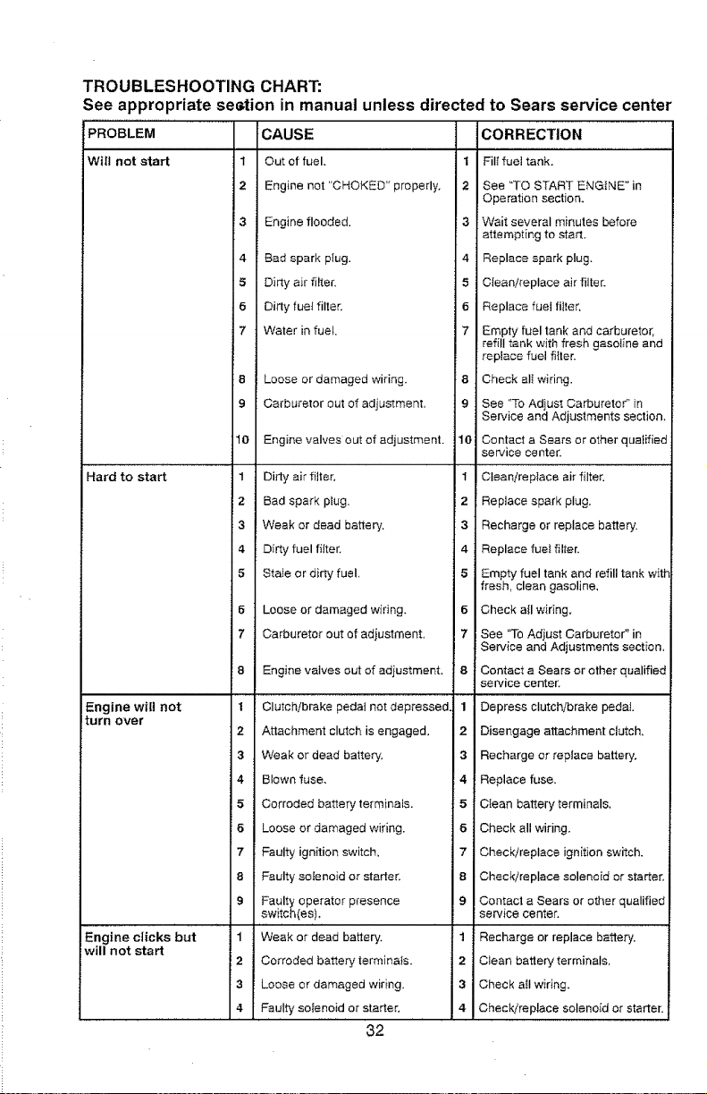
TROUBLESHOOTING CHART:
See appropriate sestion in manual unless directed to Sears service center
PROBLEM :CAUSE CORRECTION
Will not start 1 Out of fuel. 1 Fill fuel tank.
2 Engine not "CHOKED" properly, ;2 See "TO START ENGINE" in
Operation section.
F3 Engine flooded. 3 Wait several minutes before
attempting to start.
4 Bad spark plug. 4 Replace spark plug.
5 Dirty air filter. 5 Cleanireplace air filter.
6 Dirty fuef filter. 6 Replace fuel fitter.
7 Water in fueL, 7 Empty fuel tank and carburetor,
refill tank with fresh gasoline and
replace fuel fi{ter.
8 Loose or damaged wiring. 8 Check all wiring.
9 Carburetor out of adjustment, 9 See "To Adjust Carburetor" in
Service and Adjustments section,
10 Engine valves out of adjustment. 10 Contact a Sears or other qualified
service center.
Hard to start 1 Dirty air filter, 1 Cleanireptace air filter.
2 Bad spark plug, 2 RepJace spark plug.
3 Weak or dead battery, 3 Recharge or replace battery.
4 Dirty fuel fifter. 4 Replace fuel filter.
5 Stale or dirty fuel, 5 Empty fuel tank and refill tank with
fresh, clean gasoline,
6 Loose or damaged wiring, 6 Check all wir;ng.
7 Carburetor out of adjustment. 7 See "To Adjust Carburetor" in
Service and Adjustments section.
8 Engine valves out of adiustment, 8 Contact a Sears or ether qualified
service center.
Engine Will not 1 Clutch/brake pedal not depressed 1 Depress clutch/brake pedal
turn over
2 Attachment clutch is engaged, 2 Disengage attachment clutch.
3 Weak or dead battery, 3 Recharge or replace battery.
4 Blown fuse. i 4 Replace fuse.
5 Corroded battery terminals. 5 CIean battery terminals,
6 Loose or damaged wiring. 6 Check all wiring.
7 Faulty ignition switch, 7 Check/replace ignition switch.
8 Faulty soEenoid or starter. 8 Checkireplace solenoid or starter.
9 Faulty operator presence 9 Contact a Sears or other qualified
switch(es), service center.
Engine clicks 'but ' 1 'Weak or dead battery, 1 Recharge or replace battery.
will not start
2 Corroded battery terminals. 2 Clean batteryterminaIs.
3 Loose or damaged wiring. 3 Check alI wiring.
4 Faulty solenoid or starter, 4 Check/replace solenoid or starter.
32
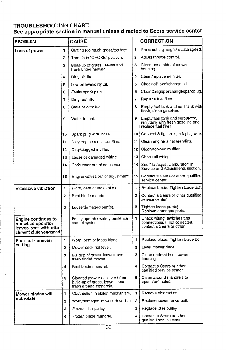
TROUBLESHOOTING CHART:
See appropriate section in manual unless directed
PROBLEM
to Sears service center
1
2
3
CAUSE
Cutting too much grass/too fast,
Throttle in "CHOKE" position.
Build-up of grass, leaves and
trash under mower.
CORRECTION
1 Raise cutting height!reduce speed
2 Adjust throttle control,
3 Clean underside of mower
housing.
4 Dirty air filter.
5 Low oil levelidirty oil,
6 Faulty spark plug.
7 Dirty fuet filter,
8 Stale or dirty fuel,
9 Water in fue!.
10 Spark plug wire loose.
11 Dirty engine air screen/fins.
12 Dirty/clogged muffter.
4 Cteanireplace air filter.
5 Check el{level/change oil
6 Ctean& regaporchangespark plug
7 Replace fuel filter.
8 Empty fuel tank and refill tank witt
fresh, clean gasoline.
9 Empty fueI tank and carburetor,
refill tank with fresh gasoline and
replace fuel rifler.
10 Connect & tighten spark plug wire
11 i Clean engine air screen/fins.
12 Cleanireptace muffler.
13
14
15
.. ,,,,,,,,,,. ,,,
Excessive vibration 1
2
3
,,, ,,,, .....
Engine continues to 1
run when operator
leaves seat with atta-
chment clutch engaged
,,,,,,,,,,,,,
Poor cut - uneven 1
cutting 2
3
4
5
, ,,,,,,_
Mower blades will t
not rotate
2
3
4
Loose or damaged wiring, 13
Carburetor out of adjustment, 14
Engine valves out of adjustment. 15
Worn, bent or loose blade, 1
Bent blade mandrel. 2
Loose/damaged part(s).
.... ,,, ,,
Faulty operator-safety presence
control system.
Worn, bent or loose blade.
Mower deck not teveI.
Buffdup of grass, leaves, and
trash under mower.
Bent blade mandrel.
Clogged mower deck vent from
build-up of grass, leaves, and
trash around mandrels.
,, ,,,,, ....
Obstruction inclutch mechanism.
Worn/damaged mower drive belt
Frozen idler puliey.
Frozen blade mandrel.
33
Check all wiring.
See "To Adjust Carburetor" in
Service and Adjustments section.
Contact a Sears or other qualified
service Center.
Replace blade. Tighten blade boil
Contact a Sears or other qualified
service center.
3 Tighten loose part(s}.
Replace damaged parts.
..... i ....
1 Check wiring, switches and
connections, If not corrected,
contact a Sears or other
1 Replace blade. Tighten btade boll
2 Level mower deck.
3 Clean underside of mower
housing.
4 Contact a Sears or other
qualified service center.
5 Clean around mandre_sto
open vent holes.
...... ,,,,,,,, ,,,,
1 Remove obstruction.
2 Replace mower drive beft.
,S Replace idler putley.
4 Contact a Sears or other
qualified service center.
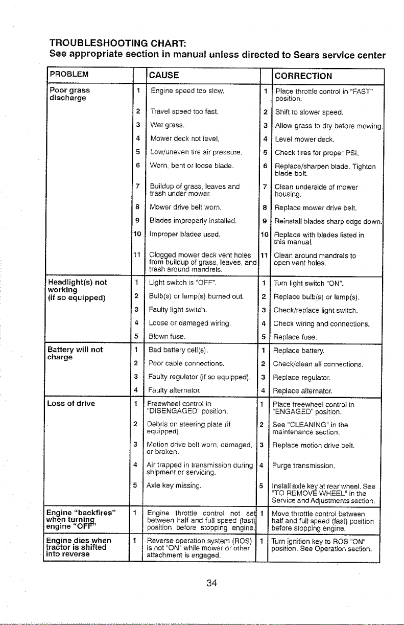
TROUBLESHOOTING CHART:
See appropriate section in manual unless directed to Sears service center
PROBLEM CAUSE CORRECTION
Poor grass 1 Engine speed too stow, 1 Place throttle control in "FAST"
discharge position,
2 Travel speed too fast, 2 Shift to slower speed.
3 Wet grass, 3 Allow grass to dry before mowing
4 Mower deck not level, 4 Level mower deck.
5 Low/uneven tire air pressure, 5 Check tires for proper PSI,
6 Worn, bent or loose b_ade. 6 Replace/sharpen blade. Tighten
blade bolt.
7 Buitdup of grass, leaves and 7 Clean underside of mower
trash under mower, housing,
8 Mower drive belt worn, 8 Replace mower drive belt,
9 Blades improperly installed, 9 Reinstall blades sharp edge down
10 Improper b_ades used. 10 Replace with blades listed in
this manual
11 Clogged mower deck vent hoses 11 Clean around mandrels to
from buildup of grass, leaves, and open vent holes,
trash around mandrels.
'Headlight(s)'"_- not I Light sw'iich is "OFF", ......... I Turn ligh;'s'witch "ON".
working
(if so equipped) 2 Bulb(s) or lamp(s) burned out. 2 Replace bulb(s) or lamp(s).
3 Faulty light switch. 3 Check/replace light switch.
4 Loose or damaged wiring, 4 Check wiring and connections.
5 Blown fuse. 5 Replace fuse,
Battery will not 1 Bad battery cell(s), 1 Replace battery.
charge
2 Poor cable connections, 2 Check/clean all connections.
3 Faulty regulator (if so equipped), 3 RepJace regulator.
4 Faulty alternator. 4 Replace alternator,
................. , ,,,, ,,,
Loss of drive 1 Freewheel control in 1 Place freewheel control in
"DISENGAGED" position. "ENGAGED" position,
2 Debris on steering plate (if ,2 See "CLEANING" in the
equipped), maintenance section,
3 Motion drive belt worn, damaged, 3 , Replace motion drive belt,
or broken.
4
5
Air trapped in transmission during 4
shipment or servicing.
Axle key missing.
,,,,,j ....
Engine "backfires" 1 Engine throttle control not set 1
when turning between hatf and full speed (fast)
engine"OFF" _osition before stopping engine,
Engine dies when : 1 Reverse operation system (ROS) 1
tractor is shifted is not "ON" while mower or other
into reverse attachment is engaged.
Purge transmission,
Insta{_ axle key at rear wheel, See
"TO REMOVE WHEEL" in the
Service and Adjustments section.
,,,,,,,....
Move throttle control between
half and full speed (fast) position
before stopping engine.
Turn ignition key to ROS "ON"
_osit{an. See Operation section,
34

NEED MORE HELP? !
You'llfindtheanswerand more on managemyhomeocom - forfree! _!i:_i
- Find this and a[[ your other product manuals online. _
, Get answers from our team of home experts. _
* Get a persona|ized maintenance plan fo_ your home. _i
o Find information and tools to help with home projects.
manage home
b_ot_ght Lo _ou _y Sea_s
35
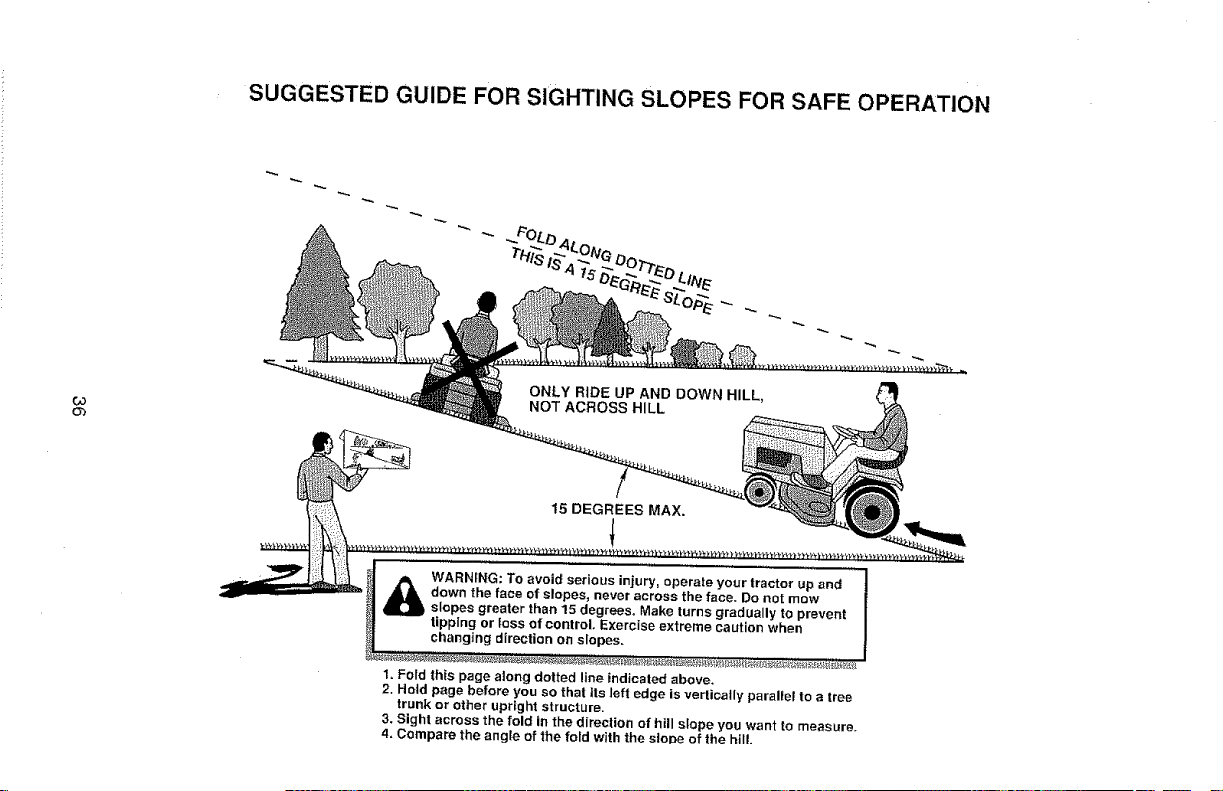
SUGGESTED GUIDE FOR SIGHTING SLOPES FOR SAFE OPERATION
Ob
,-,,,,,
ONLY RiDE UP AND DOWN HILL,
NOT ACROSS HILL
15 DEGREES MAX.
!
_b ARNfNG: To avoid serious injury, operate your tractor up and
down the face of slopes, never across the face. Do not mow
, slopes greater than 15 degrees. Make turns gradually to prevent
tipping or loss of control. Exercise extreme caution when
changing direction on slopes.
I. Fold this page along dotted line indicated above.
2. Hold page before you so that its left edge is vertically parallel to a tree
trunk or other upright structure.
3. Sight across the fold in the direction of hill slope you want to measure.
4, Compare the angle of the fold with the slope of the hill.
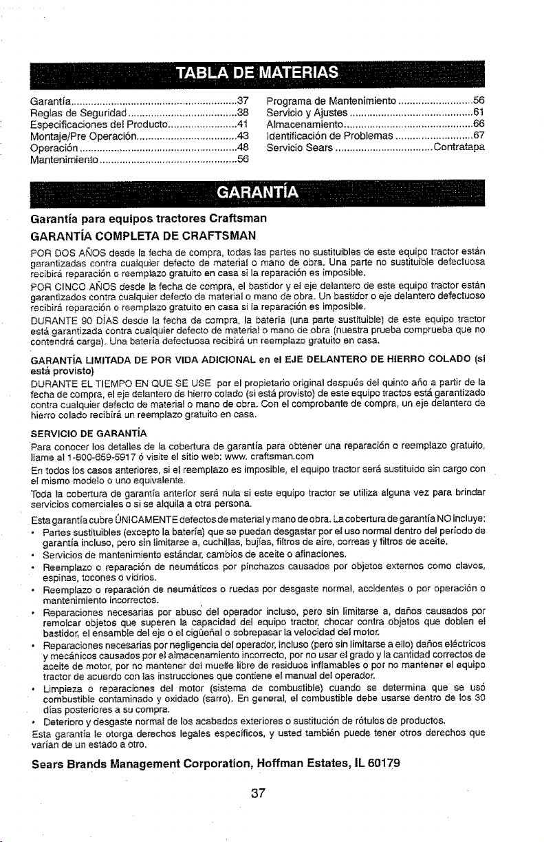
Garantia..........................................................37
Reg[asdeSeguridad......................................38
EspecifJcacionesdeIProducto........................41
MontajeiPreOperaci6n...................................48
Operaci6n.......................................................48
Mantenimiento................................................56
Programa de Mantenimiento .......................... 56
Servicio y Ajustes ........................................... 6t
Almacenarniento ............................................. 66
}dentificaci6n de Problemas ........................... 67
Servicio Sears .................................. Contratapa
Garantia para equipos tractores Craftsman
GARANTIA COMPLETA DE CRAFTSMAN
PeR DOS At_OS desde la fecha de compra, todas tas partes no sustituibles de este equipo tractor estan
garantizadas contra cualquier defecto de material o mane de obra. Una parts no sustituible defectuesa
rec[bira reparaci6n e reemp]azo gratuito en casa si ta reparaciSn es {mposible.
PeR ClNCQ AI_QS deeds Ia fecha de compra, el bastidor yet eje delantero de este equipo tractor estan
garantizados contra cualquier defecto de mater{aI o mane de obra. Un bastidor o eje delantero defectuoso
recibir=5 reparaci6n o reemplazo gratuito en casa si ta reparaci6n es imposible,
DURANTE 90 DiAS desde la fecha de compra, la bateria (una parte sust[tuJble) de este equipo tractor
eat& garantizada contra cua_quier defecto de materia_ o mane de obra (nuestra prueba comprueba que no
contendra carga). Una bateria defectuosa recibir_ un reemplazo gratuito an casa.
GARANTJA LIMITADA DE PeR VIDA ADIOIONAL en el EJE DELANTERO DE HIERRO COLADO (st
est& provisto)
DURANTE EL TIEMPO EN QUE SE USE per el propietario original despu6s del quinto aSo a part# de la
fecha de compra, el ejs detantero de hierro colado (si est_ provisto) de este equipo tractos est& garantizada
contra cualquier defecto de material o mane de obra. Con el comprobante de compra, un eje delantera de
hierro colado recibir& un reemplazo gratuito en casa.
SERVIClO DE GARANTiA
Para conocer los detal]es de la cobertura de garantia pars obtener una reparaci6n o reemplazo gratuito,
lIame al 1-800-659-5917 6 visite eI sitio web: www. craftsman.cam
En todos los cases anteriores, si ei reemplazo es imposible, el equipo tractor ser_ sustituido sin cargo con
el mismo mode]o o uno equivalente.
Toda la cebertura de garant_a anterior ser_, nula si este equipo tractor se utiliza alguna vez pars brindar
servicios comerciales o si se alquiia a otra persona.
Esta garantfa cubre 0NICAMENTEdefectosde material y mane de obra. Lacobertura de garantia NO incluye:
• Partes sustituibles (excepto la bater_a) que se puedan desgastar per el use normal dentro deI periodo de
garantia incluso, pore sin timitarae a, cuchillas, buiias, fittres de aire, correas y filtros de aceite.
• Servicios de mantenimfento est_.ndar, cambios de aceite o afinaciones.
• Reemplazo o reparaciSn de neum_ticos per pinchazos causados per objetos externos come clavos,
espinas, tocones o vidrios.
- Reemplazo o reparacion de neumAticos o ruedas per desgaste normal, accidentes o per operaci6n o
mantenimiento incorrectos.
, Reparaciones necesarias per abuse del operador incluso, pete sin limitarse a, daSos causados per
remotcar objetos qua superen la capacidad del equipo tractor, chocar contra objetos que doblan et
bastidor, el ensambie de! eje o el cigQeSaI o sobrepasar la velocida d dei motor.
• Reparaciones necesarias per negligencia del operador, incluso (pare sin limitarse a ella) daAos et_ctricos
y mec&nicos causados per et atmacenamiento incorrecto, per no usar el grade y Ia cantidad correctos de
aceite de motor, per no mantener del muelte tibre de residues inflamables o per no mantener el equipo
tractor de acuerdo con fas instruccionas que contiene ei manual deI operador.
• Limpieza o reparaciones del motor (sistema de combustible) cuando se determina que se us6
combustible contaminado y oxidado (sarro}. En general, el combustible debe usarse dentro de los 30
dias posteriores a su compra.
• Deterioro y desgaste normal de los acabados exteriores o sustituci6n de r6tulos de productos.
Esta garantia le otorga derechos legales especificos, y usted tambi6n puede tenor otros derechos que
varian de un estado a otto.
Sears Brands Management Corporation, Hoffman Estates, IL 60179
37
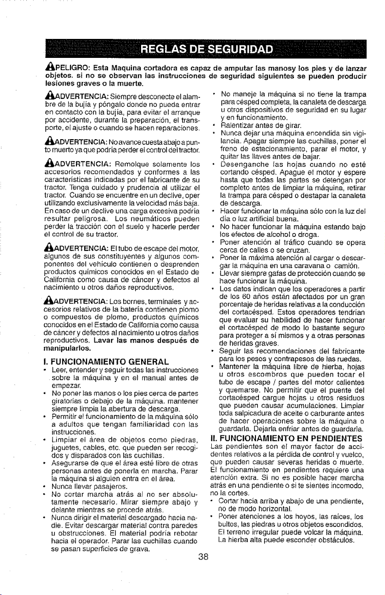
4I_PELIGRO: Esta Maquina cortadora es capaz de amputar las manosy los pies y de lanzar
objetos, si no se observan las instrucciones de segur[dad siguientes se pueden producir
lesiones graves o la muerte.
_ADVERTENC1A; Siempre desconecte el alam-
bre de la bujia y p6ngalo donde no pueda entrar
en contacto con la bujia, para evitar el arranque
por accidente, durante la preparaci6n, el trans-
porte, ef ajuste o cuando se hacen reparaciones,
_JjADVERTENCtA: No avance cuesta abajo a pun-
to muerto ya que podria perder et control dei tractor.
_ADVERTENCIA: Remolque solamente los
accesorios recomendados y conformes a las
caracteristicas indicadas per el fabficante de su
tractor, Tenga cuidado y prudencia al utilizar el
tractor, Cuando se encuentre en un declive, oper
utilizando exclusivamente Ia velocidad m&s baja.
En caso de un declive una carga excesiva podria
resultar peligrosa, Los neum&ticos pueden
perder la traccion con el suelo y hacerle perder
el control de su tractor.
_ADVERTENCIA: El tubo de escape del motor,
aIgunos de sus constituyentes y atgunos com-
ponentes del vehicuio contienen o desprenden
productos quimicos conocidos en et Estado de
California como causa de c_.ncer y defectos al
nacimiento u otros da_os reproductivos,
_DVERTENClA: Los bornes, terminales y ac-
cesorios relativos de la bateria contienen ptomo
o compuestos de plomo, productos quimicos
conocidos en el Estado de California come causa
de cancer y defectos al nacimiento u otros daSos
reproductivos. Lavar tas manos despu_s de
manipularlos.
I. FUNCIONAMtENTO GENERAL
• Leer, entender y seguir tedas las instrucciones
sobre ia m&quina yen el manual antes de
empezar.
• No poner Ias manos o los pies cerca de partes
giratorias o debajo de la m&quina, mantener
siempre limpia la abertura de descarga.
• Permitir el funcionamiento de la m#.quina s61o
a aduitos que tengan familiaridad con Ias
instrucciones.
- Limpiar et &rea de objetos como piedras,
juguetes, cables, etc, que pueden ser recogi-
dos y disparados con Ias cuchiltas.
• Asegurarse de queer a.rea est_ fibre de otras
personas antes de ponerla en marcha, Parar
ta m&quina si alguien entra en el area,
• Nunca Ilevar pasajeros.
• No cortar marcha atr,_s at no ser abso_u-
tamente necesario. Mirar siempre abajo y
delante mientras se procede atr&,s,
• Nunca dirigir el material descargado hacia na -
die. Evitar descargar materiaI contra paredes
u obstrucciones_ E! material podria rebotar
hacia el operador_ Parar las cuchJilas cuando
se pasan superficies de grava.
• No maneje Ia maquina si no tiene Ia trampa
para cesped completa, Ia canaleta de descarga
u otros dispositivos de seguridad en su lugar
yen funcionamiento,
• Ralentizar antes de girar.
• Nunca dejar una m&quina encendida sin vigi-
lancia. Apagar siempre las cuchillas, poner el
freno de estacionamiento, parar el motor, y
quitar las llaves antes de bajar,
• Desenganche Ias hoias cuando no este
cortando cesped, Apague et motor y espere
hasta que todas las partes se detengan por
completo antes de limpiar la m&quina, retirar
Ia trampa para cesped o destapar Ia canaleta
de descarga,
Hacer funcionar la m_,quina s6Io con la luz de;
dia o iuz artificia} buena.
No hacer funcionar la m&quina estando bajo
los efectos de alcohol o droga.
Poner atenci6n al tr&fico cuando se opera
cerca de caI_es o se cruzan.
Poner la m_txima atencion al cargar o descar-
gar la m&quina en una caravana o camiSn.
Uevar siempre gafas de protecci6n cuando se
hace funcionar Ia m&quina,
Los datos indican que Ios operadores a partir
de los 60 aSos estAn afectados por un gran
porcentaje de hefidas relativas a la conducci6n
del cortac,_sped. Estos operadores tendrian
que evaluar su habitidad de hater funcionar
el cortac_sped de modo Io bastante seguro
para proteger a si mismos y aotras personas
de hefidas graves.
• Seguir Ias recomendaciones del fabricante
para los pesos y contrapesos de _as ruedas.
• Mantener Ia m_tquina libre de hierba, hojas
u otros escombros que pueden tocar el
tubo de escape / partes del motor cafientes
y quemarse. No permitir que el puente del
cortacesped cargue hojas u otros residuos
que pueden causar acumulaciones. Limpiar
toda salpicadura de aceite o carburante antes
de hacer operaciones sobre la m&quina o
guardarla. Dejarla enfriar antes de guardarta,
!1. FUNClONAMIENTO EN PENDIENTES
Las pendientes son el mayor factor de acci-
dentes relatives a la perdida de control y vuetco,
que pueden causar severas hefidas o muerte,
Et funcionamiento en pendientes requiere una
atenci6n extra, Si no es posibte hacer marcha
atr&s en una pendiente o si te sientes incomodo,
no la cortes,
• Cortar hacia arriba y abajo de una pendiente,
no de modo horizontal.
• Poner atenciones a los hoyos, ias raices, los
bultos, las piedras u otros obietos escondidos,
E{ terreno irregular puede volcar la m&quin&
La hierba alta puede esconder obst&culos.
38
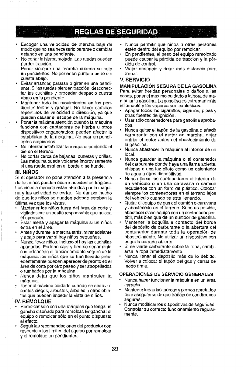
• Escoger una velocidad de marcha baja de
mode qua no sea necesafio perarse o cambiar
estando en una pendiente.
• No cortar la hierba mojade, Los ruedas pueden
perder tracci6n.
Porter siempre una marcha cuando se est&
en pendientes. No porter en punto muerto e ir
cuesta abajo,
• Ev}tar arrancar, pararse o girar en una pendi-
ente, Si }asruedas pierden tracci6n, desconec-
tar tas cuchillas y preceder despacio cuesta
abajo en fa pendiente,
• Mantener todo Ios movimientos en las pen-
dientes ientos y gradual, No hacer cambios
repentinos de velocidad o direcci6n, ya que
pueden causer et escape de la m&quina,
•Poner ta m&xima atencion cuando la m&quina
funciona con captadores de hierba u otros
dispositivos enganchados; pueden afectar Ia
estabilidad de la m&quina. No usar en pendi-
entes empinados,
• No intentar estabitizar la m&quina poniendo el
pie en el terreno.
• No cortar cerca de bajadas, cunetas y ori_Ias,
Los maquine puede volcerse imprevisamente
si una rueda est,_ en el borde o se hunde.
111.Nfi_IOS
Siet operador no pone atenci6n ala presencia
de los ni6os pueden ocurrir accidentes tr_Sgicos,
Los niSos a menudo est&n atrafdos per ta maqui-
nay las actividad de cortar. No dar per hecho
de que los niSos se queden adonde esteban la
gtltima vez que los vistas,
- Mantener los ni6os fuera del &tea de corte y
vigilados per un adulto responsable que no see
el operedor.
• Ester alerta y apagar Ia m,'_quine si un ni_os
entra en el _,ree.
• Antesydurantelamarchaatr&s, mimredelante
y abajo pare vet si hay ni_os pequeflos,
• Nunca ilevar nifios, incluso si hay las cuchiltas
epagadas, Podrian caer y herirse seriamente
o interferir con el f_ancionamiento seguro de ia
m&quina, los nir_os que se hen Ilevedo prec-
edentemente pueden aparecer de pronto en ei
_,reade corte per otto paseo y ser atropellados
o tumbados per la m&quina.
• Nunca dejar que los nir_os manipulen la
m&quine.
• Toner el m&ximo cuidado cuando se ecerce a
cantos ciegos, _trbustos, Arboles u otros obje-
tos qua pueden impedir la vista de nir_os.
IV. REMOLQUE
• Remolcar s61o con une m&quina que tenge un
gancho dise_ado pare remolcer. Enganchar el
equipo o remolcar s61o en el punto dispuesto
al efecto,
• Seguir tas recomendaciones del productor con
respecto a los limites det equipo per remofcer
y el rome!qua en pendientes,
• Nunca permitir que niSos u otras personas
est@ndentin de1equipo per remolcar,
• En pendientes, el peso deI equipo rernolcedo
puede causar Ia p@rdidade tracoi6n y la p@F
dida de control.
• Viajar despacio y dejar mas distancia para
frenar.
V. SERVIClO
MANIPULACI(3N SEGURA DE LA GASOLINA
Pare evitar betides personales o dar_os a tas
cosas, porter el m&ximo cuidado a Ia hera de ma-
nipular la gasoline, Le gasoline es extremamente
inflamaDle y los vapores son explosives.
• Apager todos los cigarrillos, cigarros, pipas y
otras fuentes de ignici6n.
• User s6Io contenedores para gesolina aproba-
dos,
• Nunca quitar el tapbn de ta gasolina o afledir
carburante con el motor en marcha, dejar
enfriar el motor antes deI abastecimiento de
la gasoline,
• Nunca abastecer la m&quina al interior de un
local,
• Nunce guardar ta m&quina o el contenedor
del carburante donde haya una I_amaabierta,
chispas o una luz piloto come un calentador
de ague u otros dispositivos.
• Nunca Ilenar tos contenedores at interior de
un vehiculo o en una caravana o cami6n
recubiertos con un forro de plAstico, Colocar
siempre los contenedores en et terreno lejos
del vehiculo cuando se estA Ilenando.
• Quiter eI equipo de gas del camiSn o caravana
y abastecerlo en el terreno, Si no es posibte,
abastecer dicho equipo con un contenedor por-
t&tiI, m&s bien que de un surtidor de gasotina.
• Mantener Ia boquilla a contacto de! borde
det dep6sito de carburante o Ia abertura del
contenedor durante toda la opereci6n de
abastecimiente. No utitizar un dispositivo con
boquilla cerrada-abierta.
• Si se vierte carburante sobre Ia rope, cambi-
arse ta ropa inmediatamente,
• Nunca ttenar el dep6sito m__sde Io debido,
Velvet a cofocar el tap6n del gas y cerrar de
mode firme.
OPERACIONES DE SERVICIO GENERALES
• Nunca hacer funcionar la m_.quina en un &tea
cerrada.
• Mantener redes las tuercas y pemos apretados
para asegurarse de que trabaja en condiciones
seguras.
• Nunca medificar !os dispositivos de seguridad,
Controtar su correcto funcionamiento regu[ar-
mente,
39
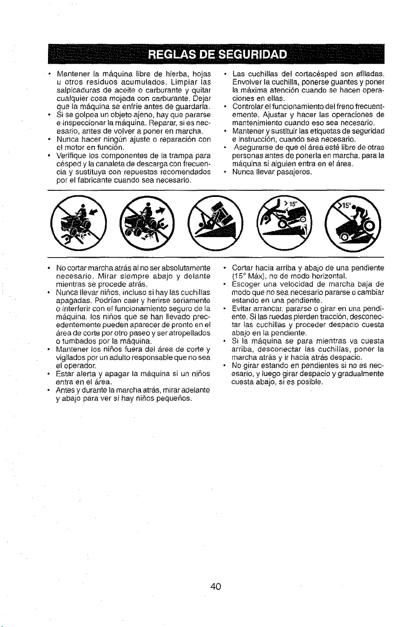
• Mantener la maquina libre de hierba, hoias
u otros residuos acumutados_ Limpiar ias
salpicaduras de aceite o carburante y quitar
cualquier cosa mojada con carburante. Dejar
que la maquina se enfrie antes de guardarla.
• Si se golpea un objeto aieno, hay que pararse
e inspeccionar la m&quina, Reparar, si es nec-
esario, antes de volver a porter en march&
• Nunca hacer ningOn ajuste o reparaci6n con
el motor en funci6n,
• Vedfique los componentes de ia trampa para
cesped y la canaleta de descarga con frecuen-
cia y sustituya con repuestos recomendados
pot el fabricante cuando sea necesario.
• Las cuchillas de! cortacesped son afiladas,
Envotver la cuchilta, ponerse guantes y poner
la maxima atenci6n cuando se hacen opera°
ciones en elias.
• Controlar et funcionamiento deI freno frecuent-
emente. Aiustar y hacer las operaciones de
mantenimiento cuando eso sea necesario.
• Mantener y sustituir las etiquetas de seguridad
e instrucci6n, cuando sea necesario.
• Asegurarse de que et Area est_ libre de otras
personas antes de ponerla en march& para ta
mAquina si aiguien entra en el Area.
• Nuncallevar pasajeros,
• No eortar marcha atrAs al no set absoJutamente
necesario, Mirar siempre abajo y delante
mientras se procede atr&s.
• Nunca llevar niSos, incluso si hay Ias cuchilfas
apagadas. Podrian caer y herirse seriamente
o interferir con et funcionamiento seguro de Ia
mAquina, los ni6os que se han Itevado prec°
edentemente pueden aparecer de pronto en el
Area de corte pot otto paseo y ser atropeilaclos
o tumbados por la maquina.
• Mantener los ni_os fuera den Area de corte y
vigilados pot un adulto responsable que no sea
el operador,
• Estar alerta y apagar la m,_quina si un nirios
entra en el &_ea.
• Antes y durante la marcha arras, mirar adelante
y abajo 38ra ver si hay nirios pequeSos,
• Cortar hacia arriba y abajo de una pendiente
(_5 ° MAx), no de modo horizontal,
• Eseoger una velocidad de marcha baia de
modo que no sea necesario pararse o cambiar
estando en una pendiente.
• Evitar arrancar, pararse o gimr en una pendi*
ente, Si Ias ruedas pierden tracci6n, desconec-
tar {as cuchilfas y proceder despacio cuesta
abaio en la pendiente,
• Si la m&quina se para mientras va cuesta
arriba, desconectar las cuchiIlas, poner la
marcha atrAs y ir hacia atrAs despacio.
• No girar estando en pendientes si no es nec-
esario, y tuego girar despacio y gradualmente
cuesta abajo, si es posible.
40
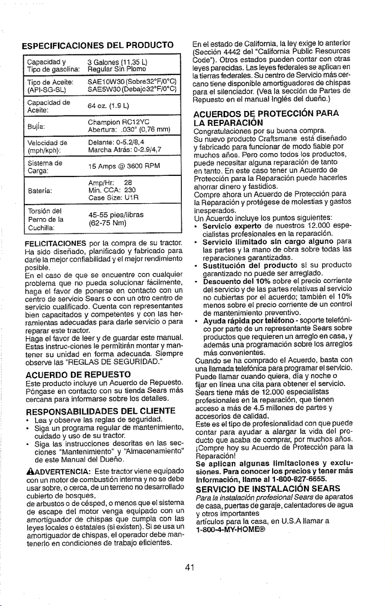
ESPECIFICACIONES DEL PRODUCTO
Capacidad y 3 Galones (11,35 L}
Tipo de gasolina: Hegutar Sin Plomo
Tipo de Aceite: SAEIOW30 (Sobre32°F/0°C)
(AP1-SG-SL) SAE5W30 (Debajo32°F/0°C)
Capacidad de
Aceite: 64 oz. (1.9 L)
Bujia: Champion RC12YC
Abertura: .030" (0,76 mm)
Velocidad de Delante: 0-5.2/8,4
(mphikph): Marcha Air&s: 0-2.9/4,7
Sistema de
15 Amps @ 3600 RPM
Carga:
AmpiHr: 28
Baterla: Min. CCA: 230
Case Size: UI R
Torsi6n deI
Perno de _a 45-55 piesilibras
Cuchilla: (62-75 Nm)
FELtCITACIONES por la compra de su tractor,
Ha sido disefiado, planificado y fabricade para
darle la mejor conflabilidad y ei rnejor rendimiento
posible,
En el caso de que se encuentre con cualquier
problema que no pueda solucionar f&cilmente,
haga el favor de ponerse en contacto con un
centro de servicio Sears o con un otro centro de
servieio cualificado. Cuenta con representantes
bien capacitados y competentes y con las her-
remientas adecuadas pare dade servicio o pare
reparar este tractor,
Haga el favor de leer y de guardar este manual.
Estas instruc-ciones Ie permitir&n montar y man-
tenet su unidad en forma adecuada, Siempre
observe las "REGLAS DE SEGURIDAD,"
ACUERDO DE REPUESTO
Este producto incluye un Acuerdo de Repuesto.
Pongase en contacto con su tienda Sears m&s
cercana pare informarse sobre los detalles.
RESPONSABILIDADES BED CLIENTE
• Lea y observe las regtas de seguridad.
• Siga un programa regular de mantenimiento,
cuidado y uso de su tractor,
• Siga las instrucciones descritas en Ias sec-
clones "Mantenimiento" y 'Almacenamiento"
de este Manual del Duello,
A0_ADVERTENCIA: Este tractor viene equipado
con un motor de combusti6n interna y no se debe
user sobre, o cerca, de un terreno no desarrollado
cubierto de bosques,
de arbustos o de c@sped,o menos que el sistema
de escape dot motor venga equipado con un
amortiguador de chispas que cumpla con las
leyes locales o estatales (si existen). Si se usa un
amortiguador de chispas, el operador debe man-
tener]o en condiciones de trabajo efic!entes.
En et estado de California, Ia ]ey exige Io anterior
(Seccion 4442 deI "California Public Resources
Code"). Otros estados pueden contar con otras
leyes parecidas, i_asleyes federales se aplican en
la tierras federates. Su centro de Servicio m_,scer-
cano tiene disponible amortiguadores de chispas
para el silenciador. (Vea la secciSn de Partes de
Repuesto en el manual lngl6s del duefio.)
ACUERDOS DE PROTECCION PARA
LA REPARACION
CongratuIaciones por su buena compra.
Su nuevo producto Craftsman® est& disefiado
y fabricado pare funcionar de modo fiable por
muchos afios. Pero como todos los produotos,
puede necesitar alguna reparaci6n de tanto
en tanto, En este caso tenor un Acuerdo de
Protecci6n para la Reparaci6n puede hacedes
ahorrar dinere y fastidios.
Compre ahora un Acuerdo de Protecci6n pare
la ReparaciSn y prot6gese de molestias y gastos
inesperados.
Un Aouerdo incluye los puntos siguientes:
• Servicio experto de nuestros t2,000 espe-
cialistas profesionales en la reparaci6n.
• Servicio ilimitado sin cargo alguno para
las partes y ta mano de obra sobre todas las
reparaciones garantizadas.
• Suetituci6n del producto si su producto
garantizado no puede set arreglado.
• Descuento de110% sobre el precio corriente
del set-vicio y de las pares relatives af servicio
no cubiertas por el acuerdo; tambien el 10%
menos sobre et precio corriente de un control
de mantenimiento preventivo.
• Ayuda rapida pot tel6tono - soporte telef6ni-
copor parte de un representante Sears sobre
productos que requieren un arreg|o en case, y
adems.s una programaci6n sobre los arreglos
m_s convenientes.
Cuando se ha comprado el Acuerdo, basta con
una llamada telef6nica para programar el servicio.
Puede tlamar cuando quiera, die y noche o
fijar en linea una cita para obtener el servicio.
Sears tiene m&s de 12.000 especialistas
profesionales en Ia reparaci6n, que tienen
acceso a m&s de 4.5 mitfones de partes y
aocesorios de calidad.
Este es el tipo de profesionalidad con que puede
contat para ayudar a alargar la vida del pro-
ducto que aceba de comprar, por muchos afios.
iCompre hoy su Acuerdo de Protecci6n para la
Reparacion!
Se aplioan algunas limitaciones y exclu-
siones. Para conocer los precios y tenet m_s
Informacibn, Ilame al t-800-827-6655.
SERVICIO DE INSTALACION SEARS
Pare la instalaciSn profesiona! Sears de aparatos
de casa, puertasde garaje, calentadores de egua
y otros importantes
articulos pare la case, en U.S.A liamar a
1-SO0-4-MY-HOME®
41
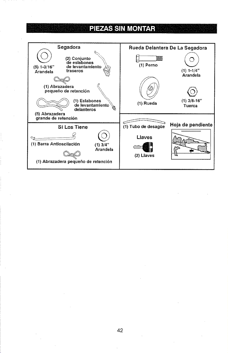
Segadora
© %,
(2) Conjunto "<:;\
de eslabones _',,,
(5) %3/16" de levantamiento _
Arandela traseros
(1) Abrazadera
peque_o de retenciSn _
___ (1) Eslabones __:_
'__' dd:,laenVtaerntoasmie nt o '_
(5) Abrazadera
grande de retencion
Si Los Tiene
(1) Barra Antioscilacibn (1) 3/4"
Arandela
(1) Abrazadera pequet_o de retencidn
Rueda Delantera De La Segadora
(1) Perno
(I) H/4"
Arandela
(1) Rueda (1) 3/8-16"
Tuerca
__ Hoja de pendiente
(1) Tubo de desagL_e
Llaves
(2) Llaves " i
42
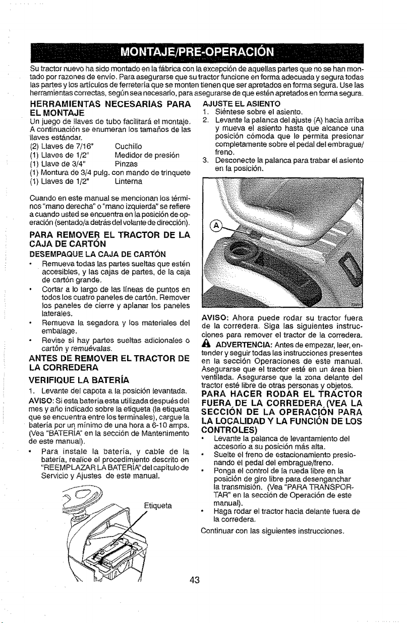
Su tractor nuevo ha sido montado en laf&brica con la excepci6n de aquellas partes que no se han mon-
tado por razones de envio, Para asegurarse que su tractor funcione en forma adecuada y segura todas
las partes y los articutos de ferreteda que se monten tienen que set apretados en farina segura. Use ias
herramientas correctas, segSn sea necesario, para asegurarse de que est_n apretados en forma segura.
HERRAMIENTAS NECESARIAS PARA
EL MONTAJE
Un juego de Ilaves de tubo facilitara el montaje,
A continuaci6n se enumeran los tama_5osde los
ilaves estAndar.
(2) Uaves de 7/16" Ouchillo
(1) Llaves de 1/2" Medidor de presi6n
{1) Llave de 3/4" Pinzas
(1) Montura de 3/4 pulg, con mando de trinquete
(1) Uaves de 1/2" Unterna
AJUSTE EL ASIENTO
t, Si6ntese sobre el asJento.
2. Levante Ia palanca del ajuste (A) hacia arriba
y mueva et asiento hasta que alcance una
posici6n c6moda que le permita presionar
completamente sobre ei pedal det embraguei
freno.
3, Desconecte la patanca para trabar e! asiento
en ta posici6n.
Cuando en este manual se mencionan tos t@rmi-
nos "mano derecha" o "mano izquierda" se refiere
a cuando usted se encuentra en ta posici6n de op-
eraci6n (sentadoia detr&s de] votante de direcci6n).
PARA REMOVER EL TRACTOR DE LA
CAJA BE CARTON
DESEMPAQUE LA CAJA DE CART()N
Remueva todas tas partes sueltas que est6n
accesibtes, y las cajas de partes, de la caja
de cart6n grande.
• Cortar a 1o largo de los lineas de puntos en
todos los cuatro paneles de cart6n. Remover
los paneles de cierre y apianar los paneles
Iaterales.
• Remueva la segadora y los materiales del
embalage.
Revise si hay partes sueltas adiciona_es o
cart6n y remu_vatas,
ANTES DE REMOVER EL TRACTOR DE
LA CORREDERA
VERIFIQUE LA BATERIA
1, Levante del capota a la posici6n tevantada,
AVISO: Siesta bateria esta utilizada despu6s dot
mes y aria indicado sobre fa etiqueta (1aetiqueta
que se encuentra entre los terminales), cargue {a
bateria por uq minimo de una hora a 6-10 amps.
(Yea "BATERIA:' en la secci6n de Mantenimento
de este manual).
• Para [nstale Ia bateria, y cable de ia
bateria, realice el procedimiento descrito en
"REEMPLAZAR LA BATERt,_'det capitulo de
Servicio y Ajustes de este manual,
_/-_._--:_:_ Etiq uat a
AVISO: Ahora puede rodar su tractor fuera
de la corredera. Siga las siguientes instruc.
clones para remover el tractor de la corredera.
ADVERTENCIA: Antes de empezar, leer,an-
tender y seguir todas Ias instrucciones presentes
en la secci6n Operaeiones de este manuat,
Asegurarse qua et tractor est6 an un &rea bien
ventilada. Asegurarse qua la zona delante deI
tractor est6 Iibre de otras personas y objetos.
PARA HAOER RODAR EL TRACTOR
FUERA DE LA CORREDERA (VEA LA
SECCION DE LA OPERACION PARA
LA LOCALIDAD Y LA FUNOtON DE LOS
CONTROLES)
• Levante Ia patanca de levantamiento del
accesofia a su posici6n m&s alta.
• Suette el freno de estacionamiento presio-
nando el pedal del embrague/freno,
Ponga el control de la rueda libra en la
posici6n de giro libra para desenganchar
la transmisi6n, (Vea "PARA TRANSPOR-
TAR" en la secci6n de Operaci6n de este
manual).
Haga rodar el tractor hacia delante fuera de
Ia corredera,
Continuar con las siguientes instrucciones.
43
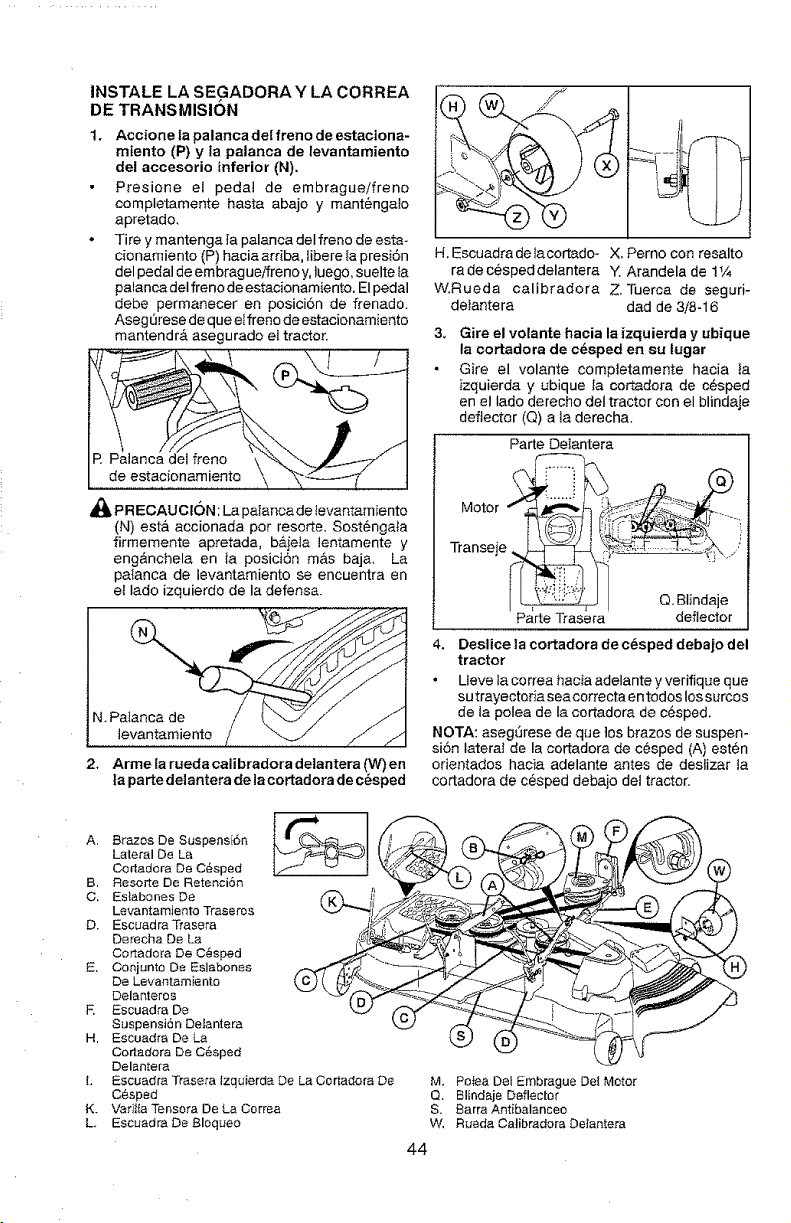
INSTALE LA SEGADORA Y LA CORREA
DE TRANSMISION
1.
Accione la palanca del freno de estaciona-
miento (P) y la palanca de levantamiento
del accesorio inferior (N),
Presione el peda! de embragueifreno
completamente haste abajo y mantengato
apretado,
Tire y mantenga la palanca deI freno de esta-
cionamiento (P) hacia arriba, libereta presi6n
del pedal de embfegue/freno y, Iuego, suelte }a
palanca deI freno de estacionamiento. El pedal
debe permanecer en posicion de frenado.
Aseg6rese de que etfreno de estacionamiento
mantendr& asegurado el tractor.
l I
R Palanca (
de estacionamiento
_I, PRECAUCI6N: La paIanca de levantamiento
(N) est& accionada per rosette. Sost6ngala
firmemente apretada, b&ieIa lentamente y
eng&nchela en la posici6n mas baja, La
pa{anca de levantamiento se encuentra en
et lade izquierdo de la defense.
2. Arme la rueda calibradora delantera (W) en
ta parte delantera de la cortadora dec_sped
H. Escuedredelacortedo- X, Perno con resalto
re de c@sped delantera Y. Arandela de ! _,4
W.Rueda celibradore Z. Tuerca de seguri-
detantera dad de 3/8-16
Gire el volante hacia la izquierda y ubique
la cortadora de cdsped en su lugar
Gire el volante comp]etamente hacia la
izquierda y ubique Ia cortadora de c6sped
en el Iado derecho deI tractor con el blindeje
deflector (Q) ala derecha.
Parte Delentere
Motor _:_: _i:_: i .......
Transeje ,_._ .................. J j,
Q. Blindaje
Parte Trasera deflector
4. Deslice la cortadora de c_sped debajo del
tractor
• Ueve la correa hacia adelante y verifique que
su trayectoria sea correcta en todos los surcos
de la polea de Ia cortedora de c6sped.
NOTA: aseg6rese de que los brezos de suspen-
si6n lateral de la eortadore de c@sped (A) esten
orientados hacie adelante antes de deslizer la
cortadora de cesped debajo det tractor.
A. Brazes De Suspens[6n _
Lateral De La
C0dadora De C6sped
B, Resoi'te De Retenci6n
Levantamiento Traseros
D, Escuadra Trasera _-ko .,,_,'S'..'_
Derecha De La
Cortadora De C_sped
E. Conjunto De Eslabones
De Levantamiento
Delanteros
R Escuadra De
Suspensi6n Delantera
H. Escuadra De La
Cortadora De CSsped
Delantera
Io Escuadra Trasera Izquierda De La Cortadora De
Cesped
K, Varitta Tensora De La Correa
L Escuadra De Bloqueo
M, Paten Dei Embrague Det Motor
Q. Blindaje Deflector
S. Barra Antibalanceo
W, Ruada Catibradore Detantera
44
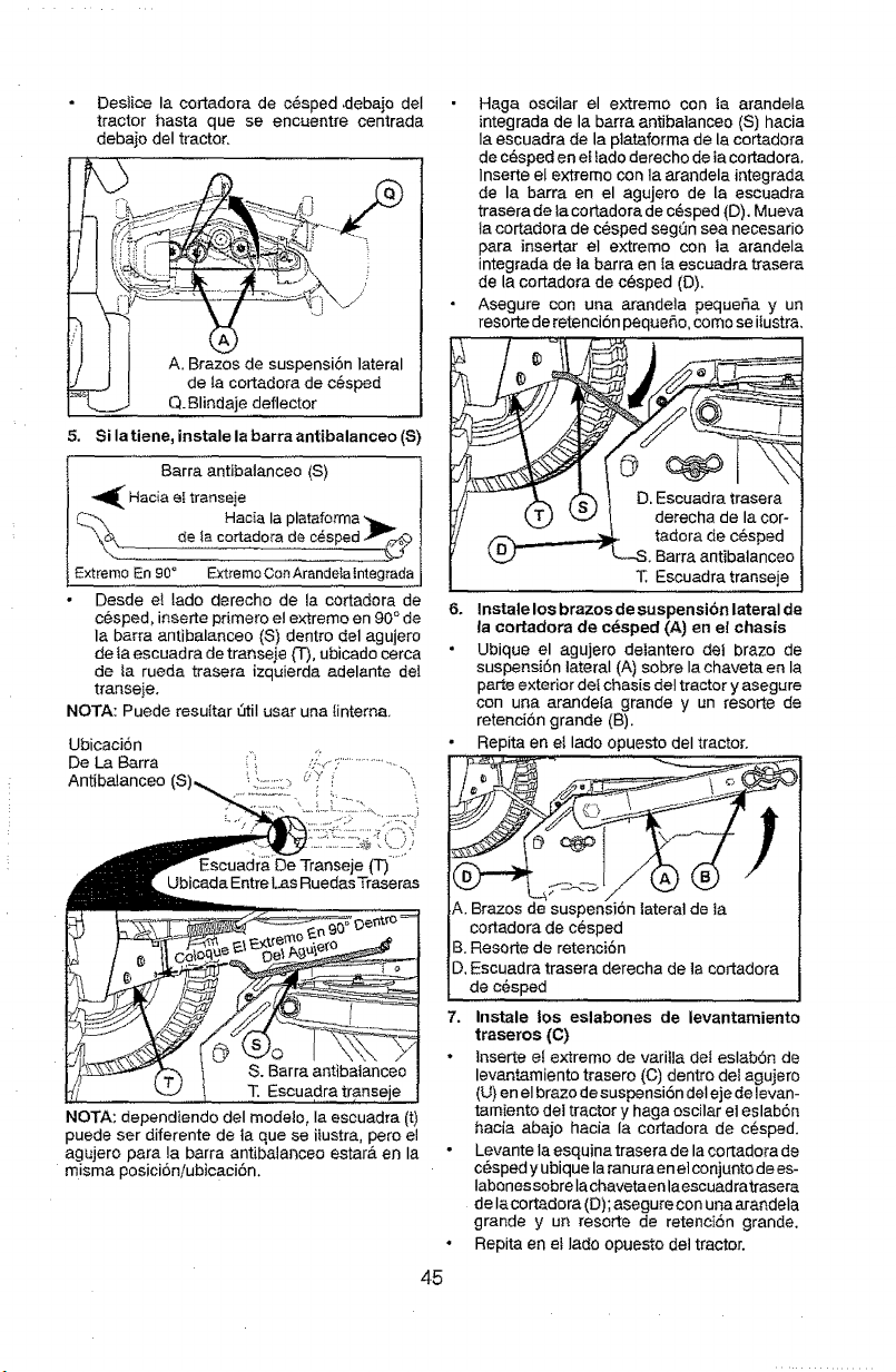
Destice la cortadora de c#sped ,debajo deI
tractor hasta que se encuentre centrada
debajo deI tractor.
A. Brazos de suspensi6n lateral
de ta cortadora de c_sped
Q. Blindaje deflector
S. Si la tiene, instale la barra antibalanceo (S)
Barra antibalanceo (S)
_ Hacia el transeje
_ Hac[a la plataforma __
de la cortadora de c_sped
Extremo En 90° Ext{emoConArandelalntegrada
Desde e_ lado derecho de la cortadora de
cesped, inserte pdmero e! extremo en 90 ° de
la barra antibalanceo {S) dentro del agujero
de ta escuadra de transeje {-1-),ubicado cerca
de _a rueda trasera izquierda adelante del
transeje.
NOTA: Puede resuttar LitiI usar una linterna.
Ubicaci6n
De La Barra
Antibalanceo
Ubicada Entre [.as Ruedas Traseras
T. Escuadra transe
NOTA: dependiendo del modelo, Ia escuadra (t)
puede ser diferente de ta que se itustra, pero el
agujero para la barra antibalanceo estar& en Ia
misma posicioniubicaci6no
45
Haga oscilar el extremo can ta arandela
integrada de la barra antibatanceo (S) hacia
la escuadra de la plataforma de la cortadora
de cesped en el fado derecho de ta cortadora.
inserte el extremo con la arandela integrada
de la barra en el agujero de la escuadra
trasera de }a cortadora de c6sped {D). Mueva
la cortadora de c_sped seg6n sea necesario
para insertar el extreme con ta arandela
integrada de la barra en ta escuadra trasera
de la cortadora de c@sped (D).
Asegure con una arandeta pequefia y un
resorte de retenci6n peque_,o, eomo se itustra.
D. Escuadra trasera
derecha de la cor-
tadora de cesped
, Barra antibatanceo
T. Escuadra transeje
6. Instate los brazos de suspensibn lateral de
la cortadora de c_sped (A) on el chasis
Ubique el agujero delantero dei braze de
suspensi6n lateral (A) sobre la chaveta ea la
parte exterior del chasis del tractor y asegure
con una arande[a grande y un resorte de
retenci6n grande (B).
Repita en el lado opuesto deI tractor.
A. Brazos de suspensi6n tateral de ta
cortadora de c@sped
B. Resorte de retenci6n
D, Escuadra trasera derecha de la cortadora
de c@sped
7, Instale los eslabones de levantamiento
traseros (C)
tnserte et extremo de varilla del eslab6n de
levantamiento trasero (C) dentro del agujero
(U) en el brazo de suspensi6n det eje de levan-
tamiento dei tractor y haga oscilar el eslab6n
hacia abajo hacia la cortadora de cesped.
Levante la esquina trasera de la cortadora de
c_sped y ubique la ranura on et conjunto de es-
Iabenes sobre Ia chavetaen la escuadratrasera
de lacortadora (D); asegure con una arandela
grande y un resorte de retenci6n grande.
Repita en et Iado opuesto det tractor.
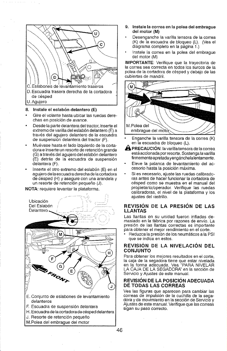
C.Eslabonesdelevantamientotraseros
D.Escuadratraseraderechadelacortadora
dec_sped
U.Agujero
8. InstaleelestabOndelantero(E)
Gireelvolantehastaubicarlasruedasdere-
chasenposiciOndeavarice.
DesdeIapartedetanteradeItractor,inserteel
extremodevarifladeleslabOndetantero(E)a
travOsdelagujerodelanterodeIaescuadra
desuspensiondeianteradeltractor(F),
Muevasehastae_tadoizquierdodetacorta-
doraeinserteunresortederetenciOngrande
(G)atravesde]agujerodeleslabOndelantero
{E)detr_.sdeiaescuadradesuspension
delantera(F).
Inserteelottoex_remodeleslabOn(E)enel
agujerodelaescuadraderechadeiacortadora
dec_sped(H)yasegureconunaarandetay
unresortederetentionpeque_o(J).
NOTA: requiere tevantar ta plataforma,
Ubicacidn :,
Del EslabOn
"k
E. Conjunto de eslabones de levantamiento
delanteros
R Escuadra de suspensi6n delantera
H, Escuadra de la cortadora de cesped delantera
J. Resorte de retenciSn pequeSo
M, Polea del embrague deI motor
9. Instale la correa en ]a potea del embrague
det motor (M)
Desenganche la varilla tensora de ta correa
(K) de la escuadra de bloqueo (L). (Vea e!
diagrama completo en la p&gina 1 .)
Instale Ia correa en Ia polea deI embrague
del motor (M)
]MPORTANTE: Verifique que la trayectoria de
Ia correa sea correcta en todos los surcos de la
polea de la cortadora de cOsped y debajo de Ias
cubiertas de mandril.
M.Polea deI
embrague del
Enganche Ia variila tensora de Ia correa (K)
en la escuadra de bloqueo (L).
PRECAUCION: la varillatensora de la correa
est& accionada por resorte. Sostengalavadlla
firmementeapretadayeng_.nchelalentamente.
Eteve Ia palanca de levantamiento del ac-
cesorio hasta la posiciOn rn,_.xima.
Si es necesario, ajuste las ruedas calibrado.
ras antes de hacer funcionar la cortadora de
c&sped como se muestra en el manual dei
propietarioioperador. Verifique tas ruedas
calibradoras, eI nivel de la piataforma y tos
ajustes del rastritlo.
REVISION DE LA PRESION DE LAS
LLANTAS
Las ttantas en su unidad fueron infladas de n
masiado en la fabrica por razones de envio. La
presiOn de las Ilantas correctas es importante
para obtener el mejor rendimiento en el corte.
• Reduzca la presion de los neum_ticos a la PSI
que se indica en estos.
REVISION DE LA NIVELACION DEL
CONJUNTO
Para obtener los mejores resultados en el corte,
la caja de/a segadora tiene que estar nivetada
en la forma adecuada. Vea "PARA NtVELAR
LA CAJA DE LA SEGADORA" en ia seccion de
Servicio y Ajustes de este manuat.
REVISION DE LA POSICION ADECUADA
DE TODAS LAS CORREAS
Vea las figuras que aparecen para cambiar Ias
correas de impulsiOn de la cuchitla de ta sega-
dora y de movimiento en ta secciOn de Servicio y
Ajustes de este manual Verifique que las correas
slgan su paso correcto.
46
REVISION DEL SISTEMA DE FRENOS
Una vez que usted haya aprendido a manejar su
tractor, vedfique qua el freno funcione correcta-
monte. Vet "PARA VERIFICAR SI FUNCIONA
BtEN EL FRENO" en et capitulo de servicio y
ajustes de este manual,
JLISTA DE REVISION
Antes de operar y de disfrutar de su tractor nuevo,
le deseamos que reclba el mejor rendimiento y la
mayor satisfaccion de este producto de calidad.
Haga el favor de reviser ta tista a continuacion:
J Se hen completado todas las instruccionesde
montaje.
,/No quedan partes sueltas en ta caja de
cart6n.
J La bateria est& preparada y cargada en forma
adecuada.
,/E1 asiento ha sido ajustado en forma c6moda
y apretado en forma segura.
JTodas las Ilantas hen sido infladas en forma
adecuada. (Para fines de envio, las ltantas se
infiaron demasiado en la f&brica.)
J'AsegQrese qua el conjunto segador est6
nivelado en forma adecuada, de tado a Iado y
desde adelante hacia atr&s, para obtener los
mejores resultados en el torte. (Las tlantas
tienen qua ester infladas en forma adecuada
pare la nivelaci6n.)
JRevise tas correas de impulsi6n y de la
segadora. Asegt3rese que recorran el paso
adecuado alrededor de las poleas y dentro de
todos los fijadores de las correas.
_/Revise el alambrado, Fijese que todas Ias
conexiones todavia est6n seguras y qua los
atambres est@nsujetos en forma adecuada.
JAntes de conducir e$ tractor, asegQrese que
el control de rueda libra este en la pos_cJon
de "transmisi6n enganchada" (Vea "PARA
TRANSPORTAR' en la secci6n de la Oper-
acion de este manual).
AI mismo tiempo qua aprende a como user su
tractor, presto atencion extra a los puntos de
importancia qua se presentan a continuacion:
/ El aceite del motor tiene que Ifegar al nivel
adecuado.
,/E_ estanque de combustible tiene que estar lleno
con gasolina sin ptomo regular, nueva y limpia.
•/ Familiaricese con todos los controles - su ubi-
caci6n y su funci6n. Operetos antes de hacer
arrancar el motor.
J Asegdrese qua el sistema de frenos est6 en
una condici6n de operaci6n segurao
JAsegurarse de que el Sistema de Presencia
det Operador y e_Sistema de Funcionamiento
Atr&s (ROS) funcionan de modo adectJado(Ver
Ias Secciones de Funcionamiento y Manteni-
miento en este manual).
,/Es importante purger la transmisi6n antes de
operar su tractor pot la primera veT. Siga Ias
instrucciones adecuadas para el empiezo y
para purger (Vea "PARA EMPESAR EL MO_
TOR" y "PARA PURGAR LA TRANSMISION"
en la secc 6n de Ia Operac 5n de este manua.
47
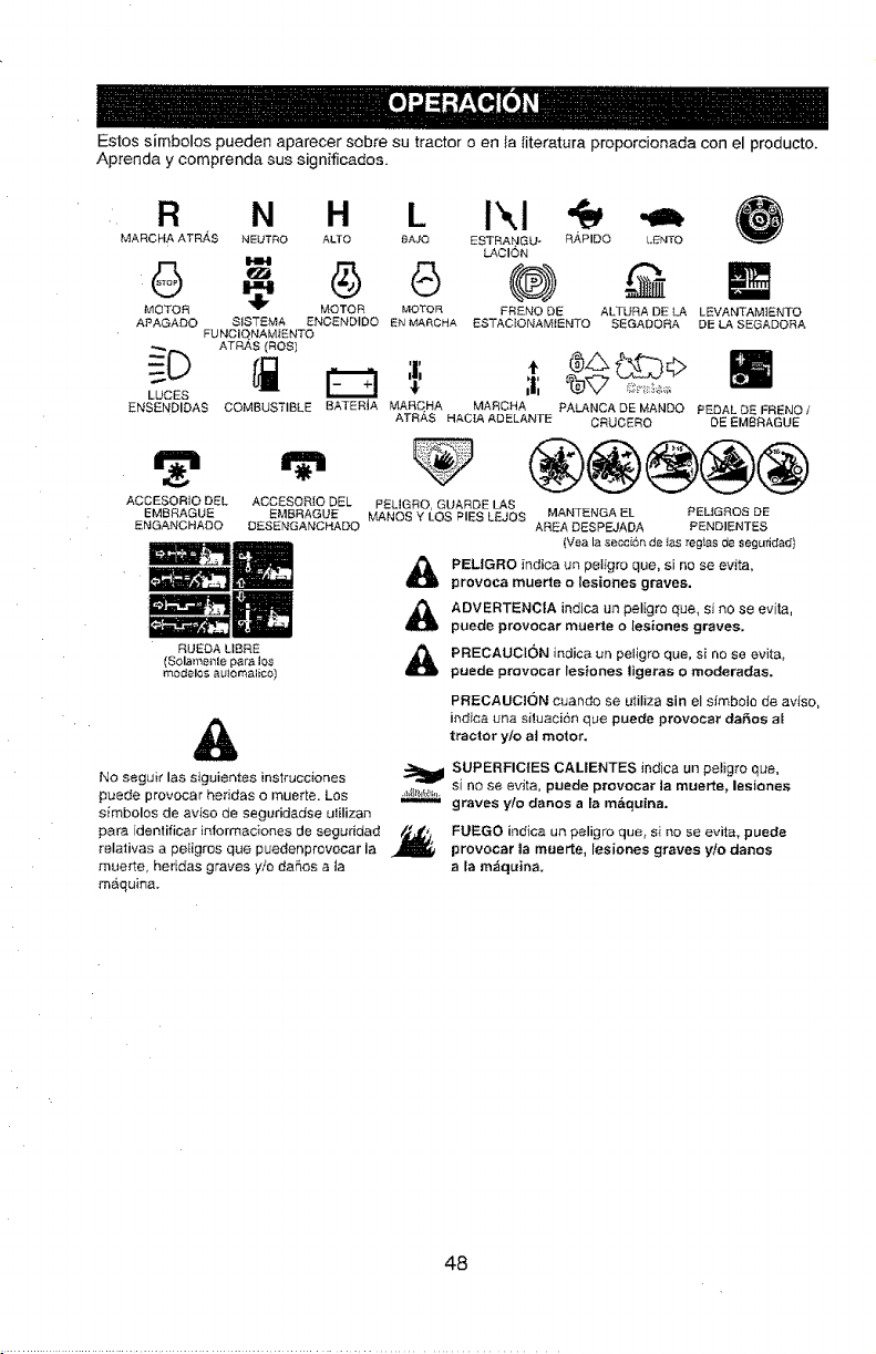
Estos simbolos pueden aparecer sobre su tractor o en }a literatura propordonada con el producto.
Aprenda y comprenda sus significados.
R
MARCHA ATR,4S
6
MOTOR
APAGADO
LUCES
ENSENDIDAS
ACCESOR]O DEL
EMBRAGUE
ENGANCHADO
N H L Ikl
NEUTRO ALTO BAJO ESTRANGU_ R,_PIDO L{_t,ITO
LACION
MOTOR MOTOR FRENO DE ALTURA DE £A LEVANTAMiENTO
SISTEMA ENCENDIDO EN MAF_CHA ESTAC_ONAMIENTO SEGADORA DE LA SEGADORA
FUt*4CIQNAM_ENTO
ATRAS (ROS)
COMBUSTIBLE BATERIA MARCHA MARCHA PALANCA DE MANDO PEDAL {bE FRENOt
ATRAS HAC]A ADELANTE CRUCERO DE EMBRAGUE
,=, ®@@@®
ACCESOR[O DEL Pf£LIGRO, GUARDE LAS
EMBRAGUE MANES Y LOS PIES LEJOS MANTENGA EL PELtGRQS DE
DESENGAMCHADO AREA DESPEJADA PENDIENTES
RUEDA LIBRE
(Solamet*lle para los
modelos aulomalico)
A
(Vea la secciSn de _as regtas de segufidad)
A ELIGRO indica un peligro que, si no se evita,
provoea muerte o lesiones graves.
A ADVERTENCIA indJca un peligro que, si no se evita,
puede provocar muerte o lesiones graves.
A RECAUCI()N indica ur_ peligro que, si no se evita,
puede provocar lesiones ligeras o moderadas,
PRECAUCI(3N cuando se utiliza sin el simboio de aviso,
ir_diea una situacion que puecte provocar dares al
tractor y/o al motor.
No seguir las siguientes instrucciones
puede provocar heddas o muerte. Los
simbolos de arise de seguridadse ulilizan
para idenlificar iniormaciones de seguddad
relativas a peligres qua pueder_provocar ia ,I_
mue_te, heridas graves y/o daSos a la
maquina.
._,_,_,_,_,_,_,_,_jSUPERFICIES CALIENTES indica un pet}g;o qua,
.,_,lll_,_,h;,,.si no sa evita, puede provocar ]a muerte_ lesiones
"""-- graves ¥/o danes a ta ma, quina.
FUEGO indica un peligro que, si no se evita, puede
provocar la muerte, lesiones graves y/o danes
a ta m_quina.
48
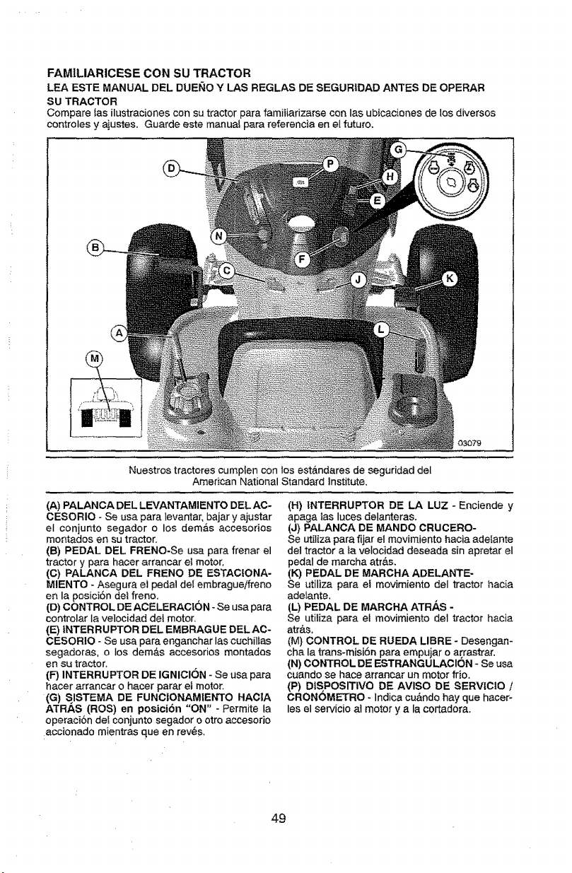
FAMILIARtCESE CON SU TRACTOR
LEA ESTE MANUAL DEL DUEllO Y LAS REGLAS DE SEGURIDAD ANTES DE OPERAR
SU TRACTOR
Compare Ias ilustracionescon su tractor para famitiarizarse con Ias ubicaciones de los diversos
controles y ajustes. Guarde este manual para referencia en eI futuro.
03079
Nuestros tractores cumplen con tos est_ndares de seguridad del
American National Standard Institute,
(A) PALANCA DEL LEVANTAMIENTO DEL AC-
CESORIO - Se usa para ievantar, bajar y ajustar
el conjunto segador o los dem_.s accesorios
montados en su tractor.
(13) PEDAL DEL FRENO-Se usa para frenar el
tractor y para hacer arrancar el motor.
(C) PALANCA DEL FRENO DE ESTACIONA-
MIENTO - Asegura el pedal del embrague/freno
en la posici6n del freno,
(D) CONTROL DE ACELERACION - Se usa para
controlar Ia velocidad dei motor.
(E) {NTERRUPTOR DEL EMBRAGUE DEL AC-
CESORIO - Se usa para enganchar las cuchil_as
segadoras, o Ios dem,_s accesorios montadas
en su tractor.
(P) INTERRUPTOR DE IGNICION - Se usa para
hacer arrancar o hacer parar et motor.
(G) SISTEMA DE FUNCtONAMIENTO HACIA
ATRAS (ROS) en posici6n "ON" -Permite la
operacion clef conjunto segador o otto accesorio
accionado mientras queen rev6s.
(H) 1NTERRUPTOR DE LA LUZ - Enciende y
apaga ]as laces delanteras.
(J) PALANCA DE MANDO CRMCERO-
Se utiliza para fijar el movimiento hacia adelante
de] tractor a fa velocidad deseada sin apretar el
pedal de marcha atr&s.
(14)PEDAL DE MARCHA ADELANTE-
Se utiliza para el movimiento deI tractor hacia
adetante,
(L) PEDAL DE MARCHA ATRAS -
Se utiliza para el movimiento del tractor hacia
atr&s.
(M) CONTROL DE RUEDA LIBRE - Desengan-
cha la trans*rnisi6n para empujar o arrastrar.
(N) CONTROL DE ESTRANGULACION - Se usa
cuando se hace arrancar un motor frio.
(P) DIS POSITIVO DE AVlSO DE SERVIClO /
CRONOMETRO - Indicacu&ndo hay que hacer-
les el servicio at motor y a la cortadora.
49
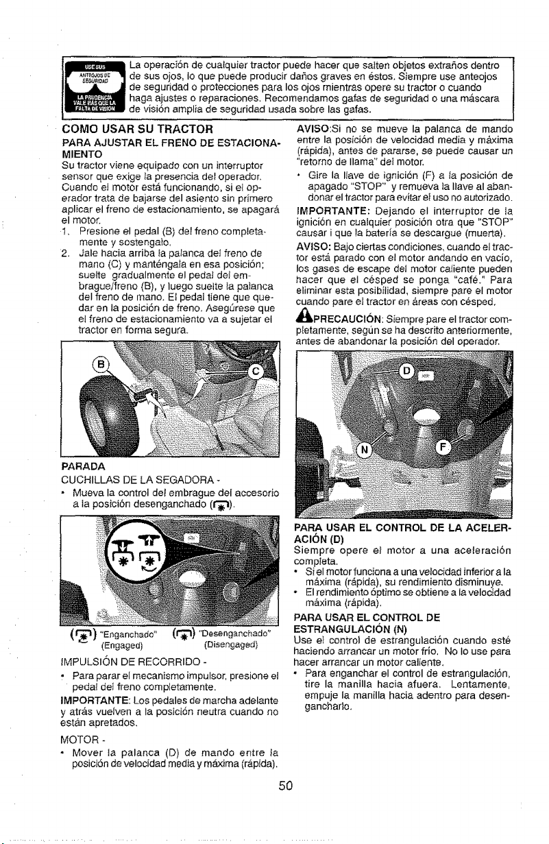
La operaci6n de cua_quier tractor puede hacer que salten obietos extrahos dentro
de sus ojos, io que puede producir daf_os graves en 6stos. Siempre use anteojos
de seguridad o protecciones para los ojos mientras opere su tractor o cuando
haga ajastes o reparaciones. Recomendamos gafas de seguridad o una m&scara
de visi6n amplia de seguridad usada sobre Ins galas.
COMe USAR SU TRACTOR
PARA AJUSTAR EL FRENO DE ESTACIONA-
MIENTO
Su tractor viene equipado con un interrupter
sensor que exige la presencia de_ operador.
Cuando et motor est_ funcionando, si e_ op-
erador trata de bajarse del asiento sin primero
aplicar el Heno de estacionamiento, se apagarA
el motor.
1. Presione el pedal (8) del freno compieta-
mente y sostengato.
2. Jale hacia arriba la pafanca del freno de
mane (C) y mant6nga_a en esa posici6n;
suette gradualmente el pedaJ clef em-
bragueifreno (B), y luego suelte Ia pa}anca
deI freno de mane. El pedal tiene que que-
dar en la posici6n de freno. Aseg_rese que
el freno de estacionamiento va a sujetar el
tractor en forma segura.
AVISO:Si no se mueve Ia palanca de mando
entre Ia posici6n de velocidad media y m&xima
(r&pida), antes de pararse, se puede causar un
"retorno de llama" det motor.
, Gire la I_ave de ignici6n (F) a la posici6n de
apagado "STOP" y remueva ta Ilave aI abam
donar el tractor para evitar et use no autorizado.
IMPORTANTE: Dejando el interrupter de la
ignici6n en cualquier posici6n otra que "STOP"
causar i que _a bateria se descargue (muerta).
AVtSO: Bajo ciertas condiciones, cuando et trac-
tor est,. parade con el motor andando en vacJo,
los gases de escape del motor caliente pueden
hacer que et c6sped se ponga "car6." Para
eliminar esta posibilidad, siempre pare el motor
cuando pare eI tractor en &reas con c6sped.
_t, PRECAUCt6N: Siempre pare el tractor com-
ptetamente, segSn se ha descrito anteriormente,
antes de abandonar la posici6n del operador,
PARADA
CUCHILLAS DE LA SEGADORA -
- Mueva Ia control de_ embrague del accesono
Ia posici6n desenganchado (t_).
"E gano., o" "Doooog. ohaao"
(Engaged) (Disengaged)
IMPULSION DE RECORRIDO -
• Para parar el mecanismo impulsor, presione et
peda_ det freno completamente.
IMPORTANTE: Los pedales de marcha adelante
y atr&s vuelven a Ia pos}ci6n neutra cuando no
est&n apretados,
MOTOR -
• Mover la palanca (D) de mando entre la
posici6n de velocidad media y m_xima (r&pida),
50
PARA USAR EL CONTROL DE LA ACELER-
AClON (D)
Siempre opere et motor a una aceieraci6n
compteta.
• Si el motor funciona a una velocidad inferior a Ia
m&xima (r_pida), su rendimiento disminuye,
o El rendimiento 6ptimo se obtiene a lavelocidad
m&xima (r&pida).
PARA USAR EL CONTROL DE
ESTRANGULACION (N)
Use el control de estrangulaci6n cuando este
haciendo arrancar un motor frio, No Io use para
hacer arrancar un motor catiente.
• Para enganchar el control de estrangulaci6n,
tire Ia manilla hacia afuera. Lentamente,
empuje Ia manilla hacia adentro para desen-
gancharto.
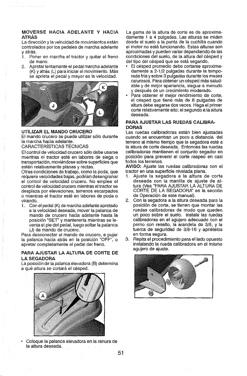
MOVERSE HACIA ADELANTE Y HACIA
ATRAS
La direcciSn y ta velocidad de movimientos est_n
controtados por tos pedales de marcha adetante
y arras.
t. Poner en marcha eI tractor y quitar el freno
de mano.
2, Apretar lentamente el pedal marcha edelante
(K) y atr&s (L) pare iniciar e_movimiento, M&s
se aprieta el pedal y mayor es la velocidad.
UTILIZAR EL MANDO CRUCERO
Et mando crucero se puede utiIizar s61o durante
la marcha hacia adelante.
CARACTERiSTICAS TECNICAS
EI control de velocidad crucero s61o debe usarse
mientras el tractor est6 en labores de siege o
transportaci6n, movi_ndose sobre superficies que
est6n reletivamente planas y rectas,
Otras condiciones de trabajo, como la poda, que
requiere velocidades bajas, podrian desengranar
el control de velocidad crucero. No emplee et
control de velocidad crucero mientras el tractor se
desplaza pot elevaciones, terrenos escarpados
o mientras el tractor est# en labores de poda o
virando,
t. Con eI pedal (K) de mercha adelante apretado
a Ia velocidad deseada, mover Ia pelanca de
mando de crucero hacia adeiante haste la
posici6n "SET" y mantenerla mientras se Ie-
vanta e_ pie del pedal, iuego soltar Ia palanca
(J) de mando de crucero.
Pare desconectar eI mando de crucero, e pujar
Ia palanca hacia atr&s en la posici6n "OFF", o
apretar completamente eI pedal deI freno.
PARA AJUSTAR LA ALTURA DE CORTE DE
LA SEGADORA
La posici6n de ta palanca elevadora (B) determine
a qua eltura se cotter& el cesped.
La game de la altura de corte es de aproxima-
damente 1 a 4 puIgadas, Las alturas se miden
desde el suelo a la punta de le cuchilla cuando
el motor no estA funcionando, Estas alturas son
aproximadas y pueden verier dependiendo de las
condiciones dot suelo, de la altura del cesped y
del tipo del cesped qua se est& segando.
• El c@sped promedio debe cortarse aproxima-
damente a 2-1/2 pulgadas durante ta tempo-
rada fria y sobre 3 pulgadas durante Iosmeses
caIurosos, Pare obtener un c_sped m&s saiud-
able y de meier apariencia, siegue a menudo
y despu@sde un crecimiento moderado.
• Para obtener eI mejor rendimiento de eorte,
el cesped que tiene m&s de 6 pulgadas de
altura debe segarse dos races. Haga eI primer
corte relativamente alto; el segundo ala altura
deseada.
PARA AJUSTAR LAS RUEDAS CALIBRA-
DORAS
Las ruedas catibradoras est&n bien ajustadas
cuando se encuentran un poco a distancia deI
terreno at mismo tiempo que la segadora est_ a
fa attura de corte deseada, Entonces ]as ruedas
calibradoras mantienen el conjunto segador en
posici6n pare prevenir el corte raspeo en casi
todos los terrenos,
AVISO: Ajuste las ruedas catibradoras con et
tractor en una superficie nivelada plana.
1. Ajuste la segadora ata eltura de corte
deseada con Ia manilta de ajuste de al-
tura (Vea "PARA AJUSTAR LA ALTURA DE
CORTE DE LA SEGADORi_' en la secci6n
de Operaci6n de este manual).
2. Con fa segadora a fa altura deseeda pare la
posici6n de corte, se tienen que montar las
ruedas calibradoras de modo que queden
un poco sobre el suelo, tnstale las ruedas
calibradoras en el agujero adecuedo con el
perno con resalto, ta arandela de 3/8, y ia
tuerca de seguridad de 3/8-16 y apdetelos
en forma segur&
3. Repita el procedimiento para el lado opuesto
instalando ta rueda calibradora en el mismo
agujero de ajuste.
• Coloque la palanca etevadora en le ranura de
!a aftura deseada.
51
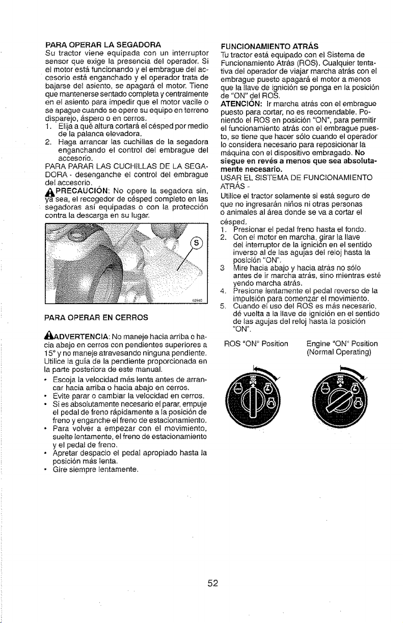
PARA OPERAR LA SEGADORA
Su tractor viene equipada con un interrupter
sensor que exige la presencia deI operador. Si
eI motor est& funcionando yet embrague del ace
cesodo esta enganchado y el operador trata de
bajarse del asiento, se apagar& el motor. Tiene
que mantenerse sentado completa y centralmente
en et asiento para impedir que el motor vacile o
se apague cuando se opere su equipo en ter{eno
disparejo. &spero o en cerros,
1. Elija a qu6 altura cortar_, et c6sped per medio
de Ia palanca elevadora,
2. Haga arrancar Ias cuchillas de la segadora
enganchando el control det ernbrague del
accesodo,
PARA PARAR LAS CUCHtLLAS DE LA SEGA-
DORA + desenganche el control dei embrague
del accesorio,
_PRECAUCl6N: No opera Ia segadora sin,
ya sea, el recogedor de c6sped complete en las
segadoras as[ equipadas o con la protecci6n
contra la descarga en su Iugar.
PARA OPERAR EN CERROS
_,DVERTENClA: No maneje hacia arriba o ha o
cia abajo en cerros con pendientes superiores a
15° y no maneie atravesando ninguna pendiente.
Utilice ta guia de la pendiente proporcionada en
la paite posteriora de este manual.
• Escoja la velocidad m&s lenta antes de arran-
car hacia arriba o hacfa abaio en cerros,
• Evite parar o cambiar la ve!ocidad en certes.
• Si es abselutamente necesario el parar, empuje
el pedal de freno r&pidamente a ta posici6n de
freno y enganche el freno de estacionamiento,
• Para volver a empezar con el movimiento,
suelte lentamente, el freno de estacionamiento
y el pedat de freno,
• Apretar despacio el pedat apropiado hasta la
posiciSn mAs fenta,
• Gire siempre tentamente.
FUNCIONAMIENTO ATR,&S
Tu tractor esta equipado con et Sistema de
Funcionamiento Atr&s (ROS). Cualquier tenta-
tiva del operador de viajar marcha atras con e!
embrague puesto apagar,_ el motor a menos
que Ia llave de igniciSn se ponga en la posici6n
de "ON" del ROS.
ATENCION: Ir marcha atras con eI embrague
puesto para cortar, no es recomendable. Po-
niendo et ROSen posici6n "ON", para permitir
el funcionamiento atrAs con et embrague pues-
to, se tiene que hacer s61o cuando el operador
Io considera necesario para reposicionar la
m_,quina con el dispositivo embragado. No
siegue en rev@s a menos que sea absotuta-
rnente neceaario.
USAR EL SISTEMA DE FUNCIONAMIENTO
ATRAS -
Utilice el tractor solamente sl estA seguro de
que no ingresar&n niSos ni otras personas
o animales al &rea deride se va a cotter el
c@sped,
1. Presionar el pedal freno hasta el fondo+
2, Con et motor en marcha, _irar ta Ilave
del interrupter de Ia ignicion en el sentido
inverse al de las agujas de} retoj hasta la
posici6n "ON".
3 Mire hacia abajo y hacia atr&s no s61o
antes de ir marcha atr&s, sine mientras est_
yendo marcha atr&s,
4, Presione Ientar._lente el pedal reverse de la
impulsion para comenzar el movimiento.
5. Cuando el use del ROSes m&s necesario,
d@ vuelta a la }lave de ignicion en el sentido
de las agujas deI reloj basra ta posici6n
"ON".
ROS "ON" Position
Engine "ON" Position
(Normal Operating)
52
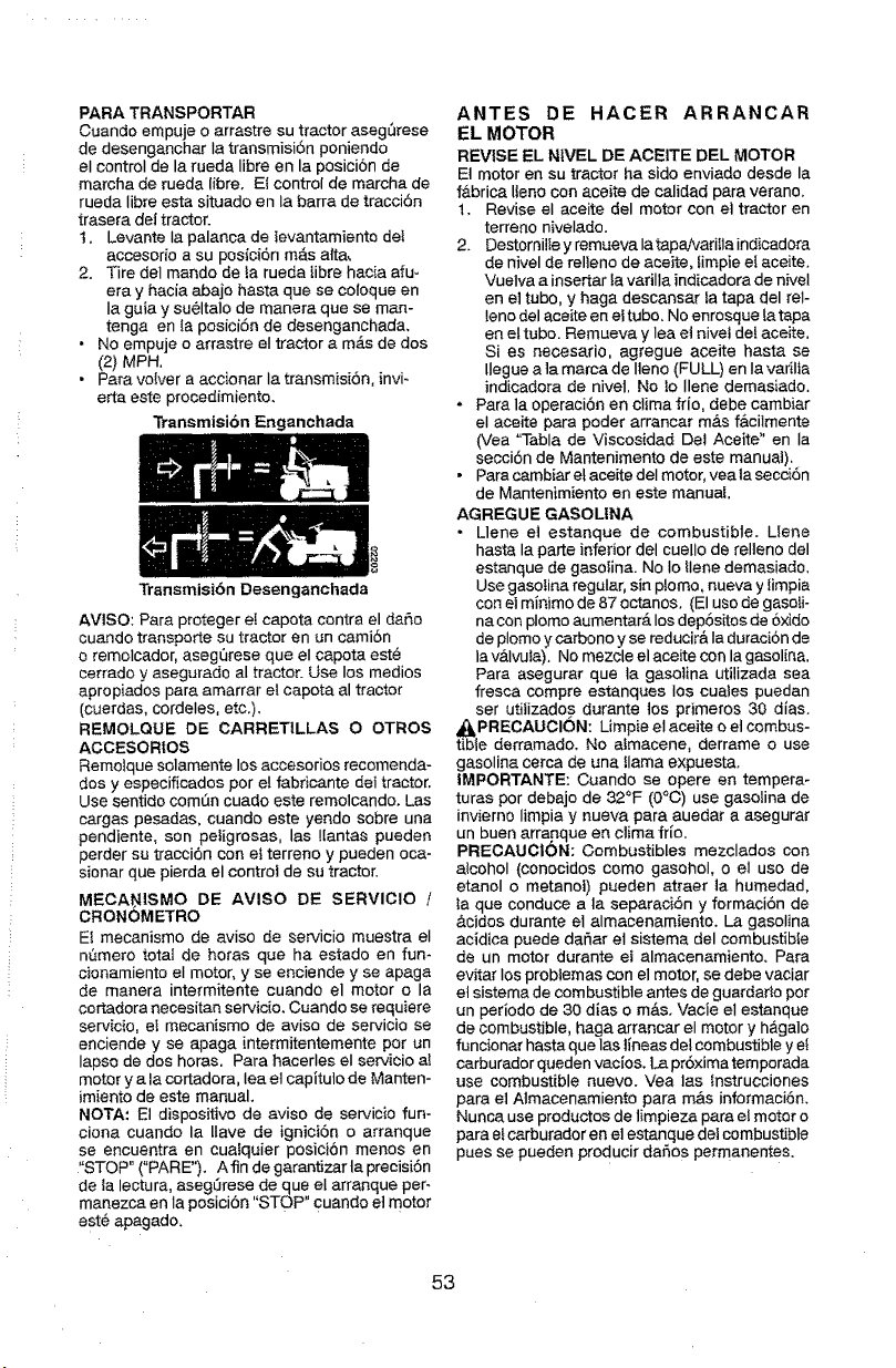
PARA TRANSPORTAR
Cuande empuje o arrastre su tractor aseg5rese
de desenganchar Ia transmisi6n poniendo
el control de la rueda Iibre en la posicion de
marcha de rueda libre. El control de marcha de
rueda libre esta situado en la barra de traccibn
trasera dei tractor.
t. Levante Ia palanca de levantamiento dei
accesor{o a su posici6n m_s otto,
2. Tire del monde de la rueda libre hacia afu-
era y hacia abajo haste que se coloque en
Ia guia y su61talo de manera que se man-
tonga en la posici6n de desenganchada.
• No empuje o arrastre eI tractor a m6.sde dos
(2) MPH,
•Para voiver a accionar la transmisi6n, invi-
erta este procedimiento.
Transmision Enganchada
Transmisi6n Desenganchada
AVISO: Pare proteger eI capote centre el daP,o
cuande transporte su tractor en un cami6n
e remolcador, asegQrese que el capote est@
cerrado y asegurado al tractor. Use los medios
apropiados pare amarrar et capote al tractor
(cuerdas, cordeles, etc.).
REMOLQUE DE CARRETILLAS O OTROS
ACCESORtOS
Remolque solamente los accesorios recomenda-
dos y especificados per el fabricante del tractor.
Use sentido comdn cuado este remolcando. Las
cargos pesadas, cuando este yendo sobre una
pendiente, son peiigrosas, las !lantas pueden
perder su tracci6n con el terreno y pueden oca-
sionar que pierda el control de su tractor.
MECA_ISMO DE AVISO DE SERVIClO /
CRONOMETRO
El mecanismo de aviso de servicio muestra el
ndmero total de betas que ha estado en fun-
cionamiento el motor, y se enciende y seapaga
de manera intermitente cuando el motor o la
certadora necesitan servicio. Cuando se requiere
servicio, et mecanismo de arise de servicio se
enciende y seapaga intermitentemente per un
lapse de des heros. Para hacerles el servicio al
motor y ala certadora, lea et capituto de Manten-
imiento de este manual.
NOTA: El dispositivo de aviso de servicio fun-
clone cuando la IIave de ignici6n o arranque
se encuentra en cualquier posici6n menos en
"STOP" ("PARE"). Afin de garantizarta precisi6n
de Ia lecture, aseg5rese de que el arranque per-
manezca en Ia posici6n "STOP" cuando el motor
est6 apagado.
ANTES DE HACER ARRANCAR
EL MOTOR
REVISE EL N1VEL DE ACEITE DEL MOTOR
Et motor en su tractor ha sido enviado desde la
f&brica lleno con aceite de ealidad para verano.
1, Revise el aceite del motor con el tractor en
terreno nivelado,
2. DestornilIe y remueva IatapaNariIla indicadora
de nivel de relleno de aceite, fimpie eI aceite.
Vuelva a inserter {a varilla indicadora de nivel
en el tube, y haga descansar la tapa del tel-
lone del aceite en eltube. No enrosque fa tapa
en el tube. Remueva y lea el nivei del aceite.
Si es necesafio, agregue aceite haste se
llegue ala marca de Ileno (FULL) en Ia varilia
indicadora de nivel, No lo Ilene demasiado.
* Pare la operaci6n en clime frio, debe cambiar
el aceite para pealer arrancar mAs f&cilmente
(Vea "Table de Viscosidad Del Aceite" en Ia
secci6n de Mantenimento de este manual),
• Para cambiar el aceite deI motor, yea la secci6n
de Mantenimiento en este manual
AGREGUE GASOLtNA
, Llene et estanque de combustible. Llene
haste la porte inferior del cuello de relteno del
estanque de gasoline. No Io Ilene demasiado,
Use gasoIina regular, sin plomo, nueva y {impia
con el minimo de 87 octanes. (El use de gasoli-
ne con plomo aumentarA los dep6sitos de oxide
de plomo y carbono y se redueir& Ia duraci6n de
la vAIvuta). No mezcle el aceite con la gasoline.
Para asegurar que ta gasoline utilizada sea
fresco compre estanques los euaies puedan
ser utiiizados durante los primeros 30 dlas.
,II_PREOAUCI6N: Limpie et aceite o et combus-
tible derramado. No atmacene, derrame o use
gasolina cerca de una llama expuesta.
IMPORTANTE: Cuando se opere en tempera-
turas per debajo de 32°F (O°C) use gasoline de
invierno limpia y nueva para auedar a asegurar
un buen arra_nque en clima fr[o.
PRECAUOION: Combustibles mezclados con
alcohol (conocidos come gasehoI, o el use de
etanoI o metanot) pueden atraer ta humedad,
taque conduce ala separaci6n y formaci6n de
&cidos durante el almacenamiento. La gasoline
acidica puede dar_ar et sistema del combustible
de un motor durante ei almacenamiento. Pare
evitar los problemas con el motor, se debe vaeiar
et sistema de combustible antes de guardarto per
un periodo de 30 dies o mAs. Vacie el estanque
de combustible, haga arrancar el motor y h&galo
funcionar haste que los tineas del combustible y ei
carburador queden vacios. La pr6xima temporada
use combustible nuevo. Vea los tnstrucciones
pare el Almacenamiento pare m&s informaci6n.
Nunca use productes de limpieza pare el motor o
pare et carburador en el estanque del combustible
pues se pueden producir da_os permanentes.
53
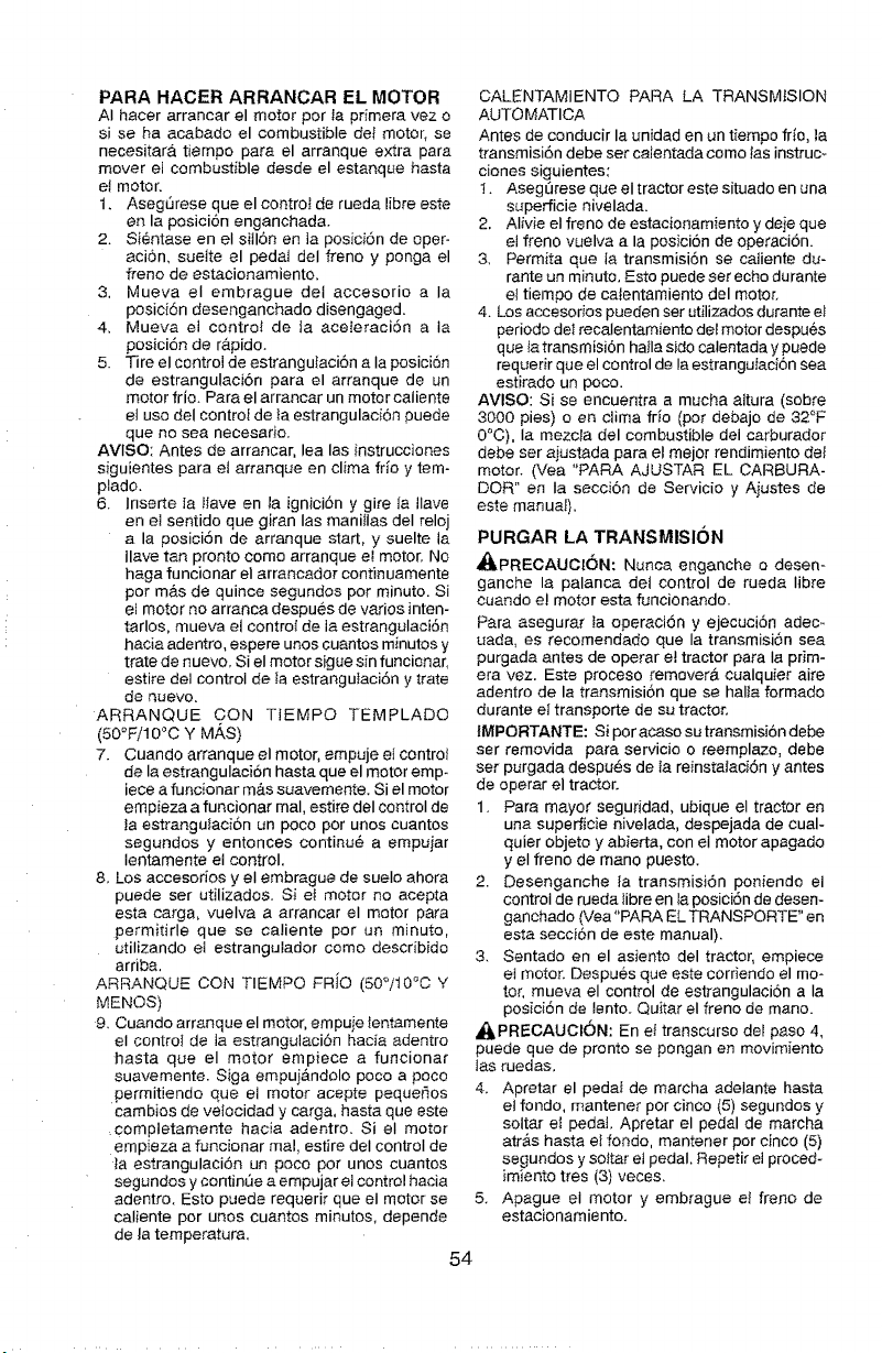
PARA HACER ARRANCAR EL MOTOR
AI hacer arrancar el motor por la primera vez o
si se ha acabado el combustible det motor, se
necesitar& tiempo para el arranque extra para
mover el combustible desde el estanque hasta
et motor.
1, AsegSrese que el controI de rueda libre este
en la posicion enganchada.
2. Sientase en el sitl6n en Ja posici6n de oper-
aci6n, suette el pedaJ del freno y ponga el
freno de estacionamiento,
3. Mueva el embrague dei accesorio a Ia
posicibn desenganchado disengaged.
4, Mueva el contro_ de _a aceieraci6n a Ia
posici6n de r&pido.
5. Tire el controJ de estrangutaci6n a Ia posici6n
de estrangulaci6n para el arranque de un
motor frio. Para el arrancar un motor caliente
et uso del contro_ de }a estrangulacion puede
que no sea necesado.
AVlSO: Antes de arrancar, lea las instrucciones
sJguientes para el arranque en clima fdo y tem-
ptado.
6. Inserte la tlave en la ignici6n y gire la Ilave
en et sentido que giran Ias maniIIas deI reloj
a la posici6n de arranque start, y suelte la
Ilave tan pronto como arranque el motor. No
haga funcionar el arrancador continuamente
pot m_.s de quince segundos pot minuto. Si
el motor no arranca despues de ratios inten-
tarlos, mueva el contro_ de ia estrangulaci6n
hacia adentro, espere unos cuantos minutos y
trate de nuevo, Si el motor sigue sin funcionar,
estire del control de Ia estrangutaci6n y trate
de nuevo.
ARRANQUE CON TIEMPQ TEMPLADO
(50°F/10°0 Y MAS)
7. Cuando arranque el motor, empuje el contro/
de la estrangulaci6n hasta que el motor emp-
iece a funcionar m&s suavemente. Si el motor
empieza a funcionar real, estire deI control de
ta estrangutacion un poco por unos cuantos
segundos y entonces eontinu6 a empuiar
tentamente et control,
8. Los accesorios y el embrague de suelo ahora 2.
puede set utilizados. Si et motor no acepta
esta carga, vuelva a arrancar el motor para
permitirle que se caliente por un minuto,
utilizando el estrangulador como describido
arriba, 3.
ARRANQUE CON TIEMPO FRiO (50°/10°C Y
MENOS)
9. Cuando arranque el motor, empuje tentamente
el controt de la estrangulaci6n hacia adentro
hasta que el motor empiece a funcionar
suavemente. Siga empui&ndolo poco a poco
permitiendo que el motor acepte pequer_os
cambios de velocidad y carga, hasta que este
,completamente hacia adentro. Si el motor
empieza a funcionar real, estire deI control de
ia estrangulaci6n un poco pot unos cuantos
segundos y continue a empujar el control hacia
adentro, Esto puede requerir que el motor se 5.
caliente por unos euantos minutos, depende
de ta temperatura,
54
CALENTAMIENTO PARA LA TRANSMiSION
AUTOMATICA
Antes de conducir la unidad en un tiempo frio, la
transmisi6n debe set calentada como las instruc-
clones siguientes:
1. AsegSrese que eI tractor este situado en una
superficie nivelada.
2, Alivie el freno de estacionamiento y deje que
el freno vuelva a la posici6n de operaci6n.
3_ Permita que la transmisi6n se caliente du-
rante un minute, Esto puede set echo durante
et tiempo de caientamiento del motor.
4. Los accesorios pueden ser utilizados durante et
periodo dot recalentamiento del motor despu6s
queta transmisi6n halla sido calentada y puede
requerir que el control de la estrangutaci6n sea
estirado un poco.
AVISO: Si se encuentra a mucha altura (sobre
3000 pies) o en elima frio (pot debajo de 32°F
0°C), la mezcla del combustible dei carburador
debe ser ajustada para el mejor rendimiento del
motor. (Vea "PARA AJUSTAR EL CARBURA.
DOR" en Ia secci6n de Servicio y Ajustes de
este manuaI),
PURGAR LA TRANSMISION
_PRECAUCI6N: Nunca enganche o desen-
ganche la palanca del control de rueda Iibre
cuando e! motor esta funcionando.
Para asegurar la operaci6n y ejecuci6n adec-
uada, es recomendado que la transmisi6n sea
purgada antes de operar el tractor para Ia prim-
era vez. Este proceso remever#, cualquier aire
adentro de la transmisi6n que se halta formado
durante el transporte de su tractor.
tMPORTANTE: Si por acaso su transmisi6n debe
ser removida para servicio o reemplazo, debe
set purgada despu6s de ia reinstaiaci6n y antes
de operar el tractor.
1. Para mayor seguridad, ubique el tractor en
una superficie nivelada, despejada de cual-
quier objeto y abierta, con el motor apagado
y el freno de mano puesto.
Desenganche ta transmisiSn poniendo el
control de rueda libre en la posici6n de desen-
ganchado (Vea "PARA EL TRANSPORTE'" en
esta secciSn de este manual).
Sentado en el asiento del tractor, empiece
et motor. Despues que este corriendo el mo-
tor, mueva el control de estrangulaci6n a Ia
posici6n de lento. Quitar el freno de mano.
_PRECAUCI6N: En et transcurso del paso 4,
puede que de pronto se pongan en movimiento
las ruedas,
4. Apretar el pedaI de marcha adelante hasta
el rondo, mantener por einco (5) segundos y
soltar el pedal, Apretar el pedal de marcha
atr&s hasta el fondo, mantener por cinco (5)
segundos y so}tar el pedal, Repetir el proced-
imiento tres (3) veces.
Apague el motor y embrague el freno de
estacionamiento.
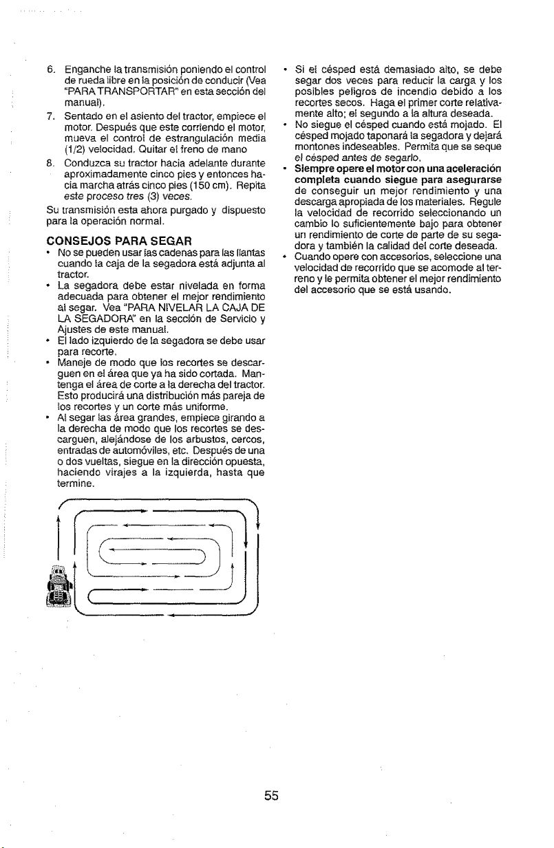
6. EnganchelatransmisiSnponiendoelcontrol
deruedalibreen ta posici6n de conducir (Vea
"PARA TRANSPORTAR" en est_ secci6n deI
manua_),
7. Sentado en el asiento del tractor, empiece el
motor. Despu6s que este corriendo el motor,
mueva el contro_ de estrangulaci6n media
(1/2) velocidad. Quitar e{ freno de mane
8. Conduzca su tractor hacia adelante durante
aproximadamente cinco pies y entonces ha-
cia marcha atr&s cinco pies (150 cm). Repita
este proceso tres (3) veces
Su transmisi6n esta ahora purgado y dispuesto
para la operacidn normal.
CONSEJOS PARA SEGAR
• No se pueden usar las cadenas para las Ilantas
cuando fa caja de la segadora est& adjunta al
tractor
• La segadora debe estar nivelada en forma
adecuada para obtener el mejor rendimiento
at segar. Vea "PARA NIVELAR LA CAJA DE
LA SEGADORA_' en Ia secci6n de Servicio y
Ajustes de este manual,
• El lade izquierdo de Ia segadora se debe usar
para recorte,
• Maneje de mode que ios recortes se descar-
guen en e! _rea que ya ha side cortada, Man-
tenga el _.reade corte a ta derecha deI tractor
Esto produck& una distribuci6n m&s pareja de
los recortes y un corte m&s uniforme
• A_segar Ias &tea grandes, empiece girando a
Ia derecha de mode que los recortes se des-
carguen, alej&ndose de los arbustes, cercos,
entradas de autom6viles, etc. Despu_s de una
o dos vueltas, siegue en Ia direcci6n opuesta,
haciendo virajes a la izquierda, basra que
termine.
f
J
• Si el c_sped eat& demasiado otto, se debe
segar dos veces para reducir Ia cargo y los
posibles petigros de incendio debido a los
recortes secos. Haga el primer corte relativa-
mente alto; et segundo a la altura deseada
• No siegue el c_sped cuando est& mojado El
cesped mojado taponar& _asegadora y dejarA
montones indeseables. Permita que se seque
el cesped antes de segarJo
• Siempre opere el motor con una aceleraoi6n
completa cuando slegue para aaegurarse
de conseguir un meier rendimiento y una
descarga apropiada de los materiales. Regule
la ve!ocidad de recorrido se{eccionando un
cambio Io suficientemente bajo para obtener
un rendimiento de corte de porte de su sega-
dora y tambi_n Ia calidad deI corte deseada.
. Cuando opere con accesorios, selecc]one una
velocidad de recorddo clue se acomode at ter-
reno y Ie permita obtener el meier rendimiento
deI aecesorio que se est& usanda.
55
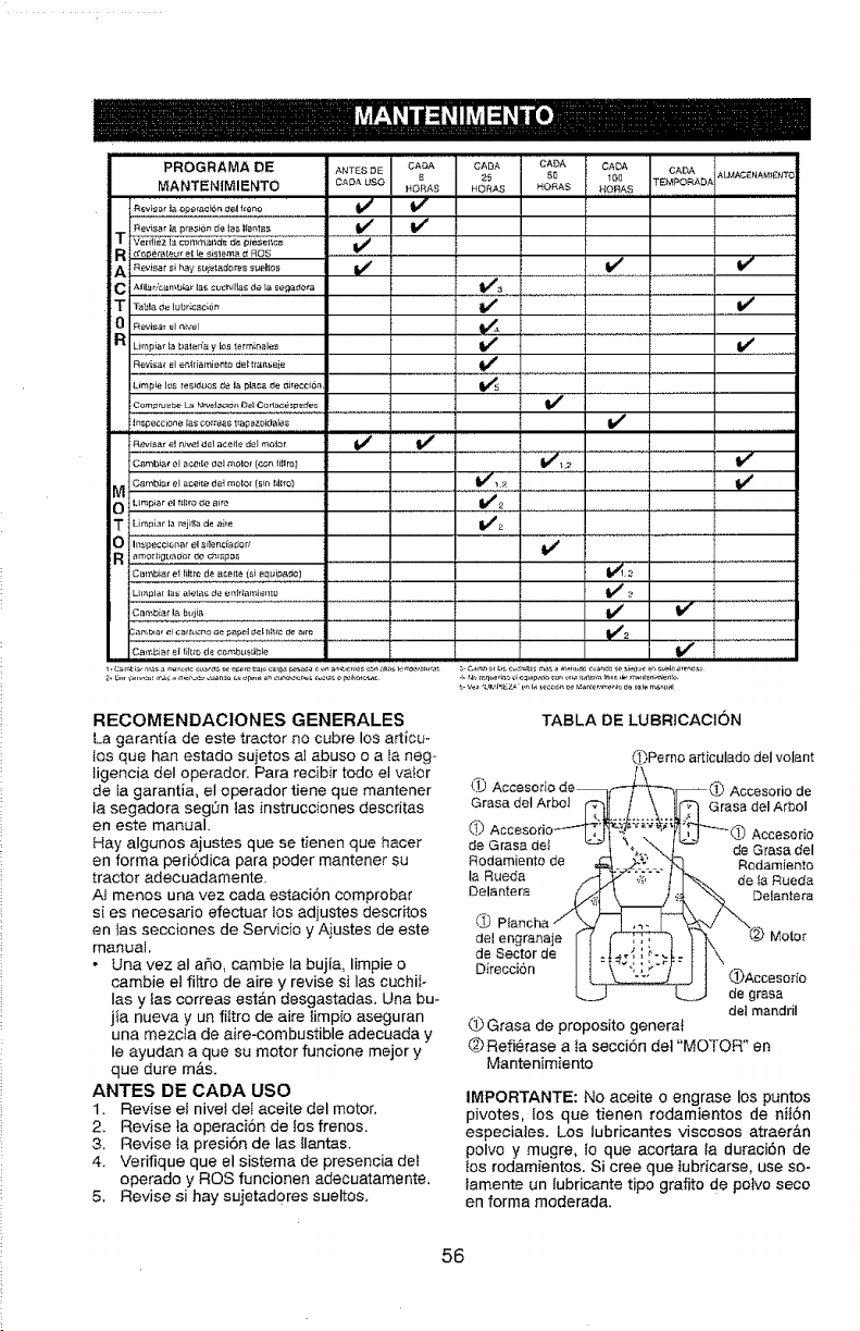
PROGRAMA DE ANTES DE CABDA CADA CADA CADA CADA ALMACENAM,$_I'tC
_5 50 1_0 TEMPORADA
MANTENIMIENTO CA_A L_SO HORAS HORAS I"{O £'_ S HOR.6,S
_evis _r la ep,_raci6_ d61 f_8 no _[_ _-
,v_i_i_,_i_c_m_i_d6'_.#_e_._,_i{c&......................
R i d_ermeurelle_sm_ _ROS
A i .......... hay ,u_et_d ....... i,os if .... _ ...................................
C i A_ilab'cambia_ _s cL_c_ili_s de ta £e#adota _3
O Revisar el r_ivel _#_ ........................................
Revi_a¢ el eP,ftia_t_i_to cte_ It_{_s_ie
L_mp_e los te _d#os _e ia p_aca de _irecci6_ _ _ _..................... ! ...........................
Inspe_c_one [as co:teas trapezok_ales _1_
Revisa._el nive_ _1e1aceile rJel mo_or V #
0 Limplar el fi{lro ee 8_re V_2 .........................................................
m Lirbpiat _a rejil;a de aide V_2
O I_specciol_ar el .£i_enciad od _ ......................
R amo[ t_g[_,_dor de c_._._p #s .....................................
Ca_biaf el Hl_m de aceite (si e_uipBdo) _'_. 2
Limplat _a_- alela_ de e_friamie_to _ 2
Cambiar la bt_iia If V r
C,_m b_a_ eI ca_[uJto _e _,oe_ _ef h_rc de a_re _#'_
=
Cambiar at _;R_O de c_mbus_ible
RECOMENDACtONES GENERALES
La garantia de este tractor no cubre los articu-
los que han estado sujetos al abuso o a la neg-
ligencia deI operador. Para recibir todo el va_or
de Ia garantia, el operador tiene que mantener
ta segadora seg0n tas instrucciones descritas
en este manual.
Hay algunos ajustes que se tienen que hacer
en forma peri6dica para poder mantener su
tractor adecuadamente.
At menos una vez cada estaci6n comprobar
si es necesario efectuar los adjustes descritos
en las secciones de Servicio y Aiustes de este
manual,
• Una vez aI a_o, cambie la bujia, limpie o
cambie el fittro de aire y revise si las cuchi}-
Ias y ias correas est&n desgastadas, Una bu-
jia nueva y un fiitro de aire {impio aseguran
una mezcta de aire-combustible adecuada y
Ie ayudan a que su motor funcione mejor y
que dure m&s.
ANTES DE CADA USO
1. Revise el nivel deI aceite del motor,
2, Revise ta operaci6n de !os frenos.
3, Revise ta presi6n de las {lantas.
4. Verifique que el sistema de presencia del
operado y ROS funcionen adecuatamente,
5, Revise si hay sujetad0res sueltos,
TABLA DE LUBRICAClON
(?)jPerno a_iculado dei volant
{,_) Accesorio de--
Grasa deI ArboI Grasa del ArboI
_) Accesorio
de Grasa del de Grasa del
Rodamiento de Rodamier_to
la Rueda de la Rueda
Delantera Delantera
O
del engranaje Motor
de Sector de
Direcci_n l(l(l(l(_Accesodo
de grasa
del mandril
Grasa de proposito genera{
(_)Refi_rase a ia secci6n det "MOTOR" en
Mantenimiento
IMPORTANTE: No aceite o engrase los puntos
pivotes, {os que tienen rodamientos de nii6n
especiaies. Los tubricantes viscosos atraer&n
polvo y mugre, Io que acortara la duraci6n de
los rodamientos. Si cree que tubricarse, use so-
lamente un lubricante tipo grafito de potvo seco
en forma moderada.
56
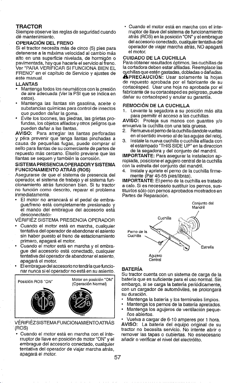
TRACTOR
Siempre observe las reglas de seguridad cuando
d6 mantenimiento.
OPERACI6N DEL FRENO
Si el tractor necesita m&s de cinco (5) pies para
detenerse a la m&xima velocidad al cambio m_.s
a_to en una superficie nivelada, de hormigSn o
pavimentada, hay qua hace#e el servicio al freno.
Ver "PARA VERIFtCAR St FUNCIONA BIEN EL
FRENO" en el capltutc de Servicio y ajustes de
este manual.
LLANTAS
• Mantenga todos los neuma.ticos con Ia presiSn
de aire adecuada (Ver ta PSi que se indica en
estos),
• Mantenga tas Ilantas sin gasolina, aceite o
substancias qufmicas para control de insectos
que pueden dafiar Ia goma,
• Evite los tocones, Ias piedras, las grietas pro-
fundas, tos objetos afilados y otrcs peligros que
pueden dafiar a tas Ilantas.
AVlSO: Para arreglar {as tlantas perforadas
y p_ra prevenir que tenga Ilantas pinchadas a
causa de pequefias fugas, puede comprar el
sello para Ilantas de su comerciante de partes de
repuesto mas cercano. Elsetlo previene que Ias
Ilantas se sequen y tambi6n la corrosi6n.
SISTEMA PR ESENCtA OPERADOR Y SISTEMA
FUNCIONAMIENTO ATR,,_S (ROS)
Asegurarse de que e! sistema de presencia del
operador, el sistema de trabajo y el sistema fun-
cionamiento atr&s funcionen bien. Si tu tractor
no funciSn coma descrito, reparar eI probiema
inmediatamente.
• El motor no arrancar#, si el pedal de embra-
gue/freno est#, completamente presionado y
et mando deI embrague deI accesorio est,.
desconectado:
VER_F_I_Z StSTEMA PRESENCIA OPERADOR
- Cuando el motor est,. en marcha, cualquier
tentativa del operador de abandonar el asiento
sin haber puesto et freno de estacionamiento
primero, apagar& et motor.
• Cuando el motor estA en marcha y el embra-
gue del accesorio est& conectado, cualquier
tentativa deI operador de abandonar el asiento,
apagarA el motor.
• Et embrague deI accesodo no tendria que funcio-
nat nunca si e! operador nc est#. en su asiento,
Posici6n ROS "ON"
V¢:RtFIEZSISTEMA FUNCIONAMIENTOATRAS
(ROS)
* Cuando el motor est& en marcha con el inte-
rruptor de Ilave en pesici6n de motor "ON" y el
embrague del accesorio conectado, cuaiquier
tentativa det operador de viajar marcha atr_.s,
• Cuando el motor est& en marcha con el inte-
rruptor de tlave dei sistema de funcionamiento
atr_s (ROS) en ta posiciSn "ON" y el embrague
del accesodo conectado, cualquier tentativa del
operador de viajar marcha art&s, NO apagar_,
el motor.
CUIDADO DE LA CUCHtLLA
Para obtener resultados6ptimcs, tas cuchillas de
Ia cortadora deben estar afitadas. Reemplace las
_chillas que este"n gastadas, dobladas o darTadas.
PREOAUOtON: Usar sotamente la hojas
de repuesto aprobada per el fabricante de su
cortac@sped. Usar una hoja no aprobada per el
fabdcante de su corL_c@spedes peligroso, puede
da[_ar su cortac_sped y anular su garantia.
REMOCtON DE LA CUCHILLA
1. Levante Ia segadora a su pesicibn m#,salta
para permitir el acceso alas cuchillas.
AVISO: Proteja sus manos con guantes ylo
envuelva la cuchilla con una tela gruesa.
2. Remueva eI pemo de iacuchiItadandole vueltas
en el sentido inverso ai de Iasagujas del reloj,
3, lnstale [a nueva cuchilla o cuchilla afitada con
et estampado "THIS SIDE UP" en la direction
de ta segadora y del conjunto del manddl.
IMPORTANTE: Para asegurar la instalacion ap-
ropiada, posicione el agujero central de Ia cuchilla
con la estrelta deI conjunto deI mandril.
4, Instale y apriete et perno de la cuchilla firme-
mente (Par 45-55 pies/libras),
IMPORTANTE: El perno de la cuchitla es tratadc
a cato. Si es necessario sustituir tos pernos, sus-
tituidos s61ocon pernos aprobados mostrados en
Partes de Reparacion,
Conjunta del
Mandril
Cuchi_ia .-'\ ,,_
/ o,,o,Io
Agujero
Central
BATER1A
Su tractor cuenta con un sistema de carga de Ia
bateria que es suficiente para el use normal. Sin
embargo, si se carga la bateria periodicamente,
con un cargador de autom6viies, se prolongar_
su duraci6n.
• Mantenga ta bateria y ios terminales limpios.
• Mantenga los pemos de ta batefia apretados.
• Mantenga los agujeros de ventilaci6n peque-
5as abiertos.
- Vuetva a cargar de 6-10 amperes per t hora,
AVISO: La bateria deI equipo original de su
tractor no becesita servicio, No intente abrir o
remover las tapas o cubiertas. No esnecesado
afiadir o verificar el nivel del elec_rSiito,
apagar& el motor.
57
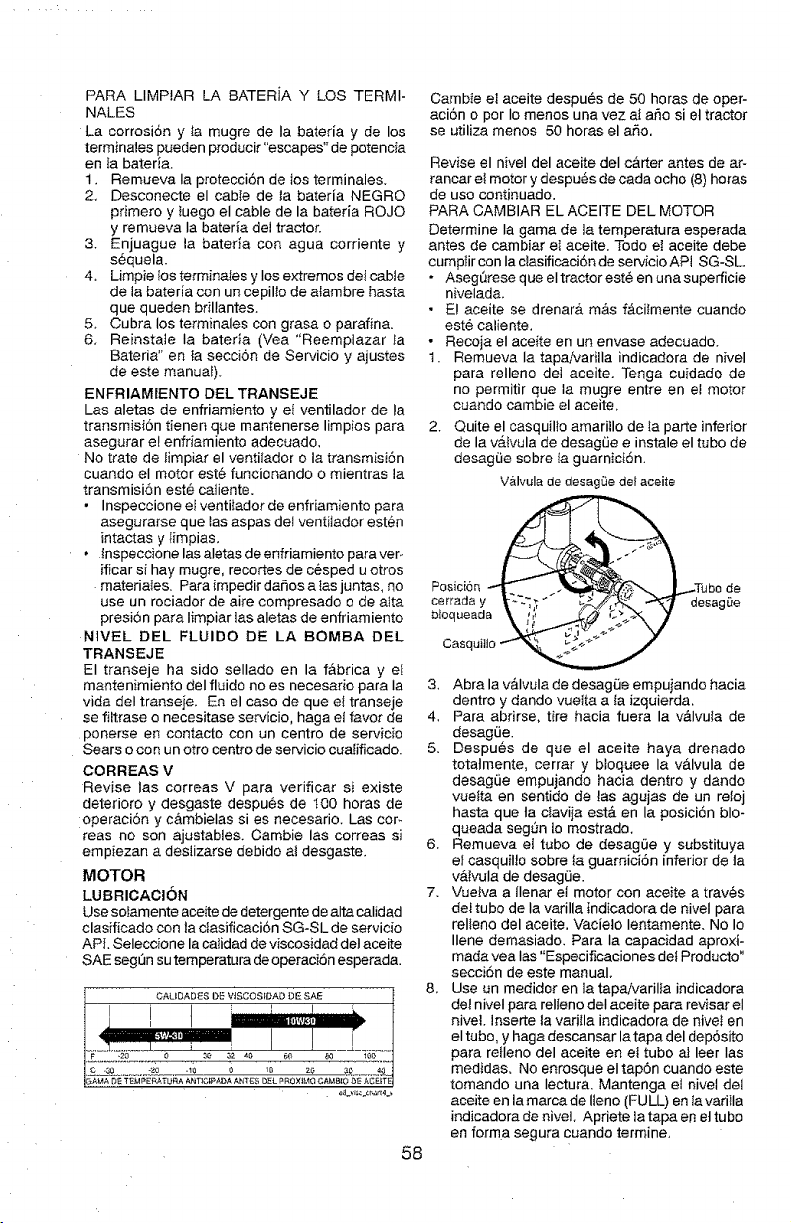
PARA LIMPIAR LA BATERiA Y LOS TERMI-
NALES
La corrosi6n y la mugre de Ia bateria y de los
terminales pueden producir"escapes" de potencia
en la bated&
1. Remueva Ia protecci6n de los terminales.
2, Desconecte el cabIe de ta bateria NEGRO
pdmero y luego el cable de la bateria ROJO
y remueva la bateria del tractor.
3. Enjuague la bateria con agua corriente y
s6quela.
4. Limpie los terminales y los extremos det cable
de la bateria con un cepillo de atambre basra
que queden brillantes.
5. Cubra los terminales con grasa o parafina.
6, Reinstale Ia bateria (Vea "Reemptazar Ia
Bateria" en la secciSn de Servicio y ajustes
de este manuaI),
ENFRIAMIENTO DEL TRANSEJE
Las aletas de enfriamiento yet ventilador de la
transmisi6n tienen que mantenerse limpios para
asegurar el enfriamiento adecuado,
No trate de timpiar el venti_ador o la transmisiSn
cuando el motor este funcionando o mientras la
transmisi6n est_ catiente.
• Inspeccione el ventilador de enfriamiento para
asegurarse que Ias aspas det ventiiador esten
intactas y limpias.
• lnspeccione las aletas de enfriamiento para ver-
ificar si hay mugre, recortes de cesped u otros
materiates. Para impedir daSos a {as juntas, no
use un rociador de aire compresado o de alta
presion para Iimpiar Ins aletas de enfriamiento
NIVEL DEL FLUIDO DE LA BOMBA DEL
TRANSEJE
El transeje ha sido sellado en la f&brica y el
mantenimiento deI fluido no es necesado para Ia
vida deI transeje. En el caso de queet transeje
se filtrase o necesitase servicio, haga el favor de
ponerse en contacto con un centro de servicio
Sears o con un otro centro de servicio cualificado.
OORREAS V
Revise Ins correas V para verificar si existe
deterioro y desgaste despues de t00 horns de
;operacion y c&mbielas si es necesario. Las coF
teas no son ajustables. Cambie las correas si
empiezan a deslizarse debido ai desgaste.
MOTOR
LUBRICACION
Use soiamente aceite de detergente de alta calidad
clasificado con la ctasificaci6n SG-SL de servido
APL Seleccione la catidad de viscosidad deI aceite
SAE seg[3n su temperatura de operaciSn esperada.
CALIDAD_S DE VtSCOSfi_AD DE SAE
58
Cambie el aceite despu_s de 50 horas de oper-
aci6n o per Io menos una vez ai aSo si et tractor
se utiliza menos 50 horns el aF,o.
Revise el nivel del aceite deI c&rter antes de ar-
rancar el motor y despu_s de cada ocho (8) horns
de uso continuado.
PARA CAMBIAR EL ACEITE DEL MOTOR
Determine Ia gama de la temperatura esperada
antes de cambiar et aceite, Todo et aceite debe
cumptir con Ia clasificaci6n de servicio API SG-SL.
* AsegQrese que el tractor est_ en una superficie
nivelada.
• E! aceite se drenar& m&s f&cilmente cuando
este caliente,
1.
2.
Recoja el aceite en un envase adecuado.
Remueva la tapaivariila indicadora de nivel
para relleno del aceite. Tenga cuidado de
no permitir que la mugre entre en et motor
cuando cambie el aceite.
Quite el casquillo amarillo de Ia parte inferior
de la valvula de desagLie e instale el tubo de
desagLie sobre ta guarniciSn.
Valvula de desagLie de} aceite
Posicion be de
Casquilto
3, Abra la v_lvula de desagfJe empujando hacia
dentro y dando vuelta a la izquierda,
4. Para abdrse, tire hacia fuera la v&lvula de
desagLie.
5. Despues de que el aceite haya drenado
totalmente, cerrar y bloquee la valvula de
desag_ie empujando hacia dentro y dando
vuelta en sentido de las agujas de un retoj
hasta que Ia olavija est& en la posici6n blo-
queada seg_n lo mostrado,
6. Remueva el tubo de desag(Je y substituya
el casquiHo sobre ta guamici6n inferior de ta
v&tvula de desagLie.
7, Vuelva a Ilenar el motor con aceite a traves
dei tubo de la varilla indicadora de niveI para
relleno del aceite. Vacieto Ientamente, No Io
Ilene demasiado. Para Ia capacidad aproxi-
mada yea Ias "Especificaciones del Producto"
seccidn de este manual,
8, Use un medidor en fa tapa/varilla indicadora
del niveI para relleno deI aceite para revisar el
hive], lnseC_e la varilla indicadora de nivet en
el tubo. y haga descansar la tapa del depSsito
para retleno del aceite en et tubo al leer Ins
medidas, No enrosque el tapdn cuando este
tomando una Iectura. Mantenga el nivel del
aceite en la marcade Ileno (FULL) en la varilIa
indicadora de nivel, Apriete la tapa en et tubo
en forma segura cuando termine,
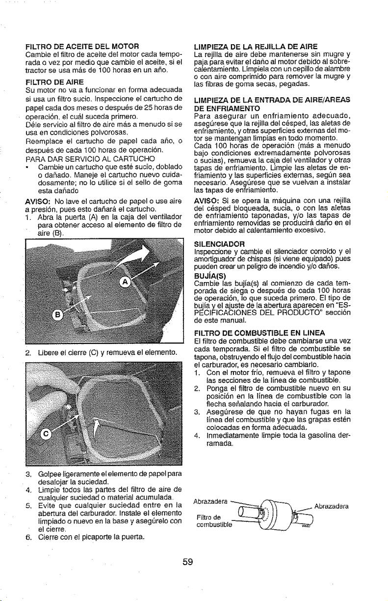
FILTRO DE ACEITE DEL MOTOR
Cambie el filtro de aceite deI motor cada tempo-
rada ovez por medic que cambie el aceite, si el
tractor se usa m_.s de 100 horas en un argo,
FILTRO DE AIRE
Su motor no va a funcionar en forma adecuada
si usa un filtro sucio, Inspeccione et cartucho de
papel cada dos meses o despu6s de 25 horas de
operaci6n, el cu&l suceda primero.
D_le servicio at fiitro de aire mAs a menudo si se
usa en condiciones polvorosas,
Reemplace el cartucho de papel cada afio, o
despues de cada 100 horas de operaci6n.
PARA DAR SERVlCIO AL CARTUCHO
• Cambie un cartucho que est6 sucio, doblado
o daSado. Maneje ei cartucho nuevo cuida_
dosamente; no Io utilice si e! sello de goma
esta dafiado
AVISO: No tave el cartucho de papel o use aire
a presi6n, pues esto daSar& e] cartucho,
1. Abra la puerta (A) en la caja del ventilador
para obtener acceso al elemento de fittro de
aire (B).
2, Libere e_cierre (C) y remuev a el elemento,
LIMPIEZA DE LA REJILLA DE AtRE
La rejilla de aire debe mantenerse sin mugre y
paja para evitar el da_o al motor debido a! sobre*
caIentamiento. Limpiela con un cepillo de aiambre
o con aire comprimido para remover la mugre y
las fibras de goma secas, pegadas.
LIMPIEZA DE LA ENTRADA DE AIREiAREAS
DE ENFRIAMENTO
Para asegurar un enfriamiento adecuado,
aseghrese que ta rejilla del c_sped, las aletas de
enfdamiento, y otras superficies extemas de_ mo-
tor se mantengan limpias en todo momento.
Cada 100 horas de operaci6n (mAs a menudo
bajo condiciones extremadamente polvorosas
o sucias), remueva la caia del ventilador y otras
tapas de enfdamiento. Limpie las aletas de en-
friamiento y tas superficies extemas, seghn sea
necesario. Aseg0rese que se vuelvan a instafar
las tapas de enfriamiento.
AVlSO: Si se opera Ia m&(]uina con una rejilla
dei c6sped bloqueada, sucia, o con las aIetas
de enfriamiento taponadas, yio las tapas de
enfriamiento removidas se producir& dar_o en el
motor debido aI calentamiento excesivo,
SILENCIADOR
Inspeccione y cambie el silenciador corroido y el
amo_guador de chispas (si viene equipado) pues
pueden crear un peligro de incendio y/o dafios.
BUJiA(S)
Oambie las bujia(s) al comienzo de cada tem-
porada de siega o despuL,s de cada 100 horas
de operaci6n, to que suceda primero, El tipo de
buiia y el ajuste de la abertura aparecen en "ES-
PECIFICACIONES DEL PRODUCTO" secci6n
de este manual.
FILTRO DE COMBUSTIBLE EN LINEA
El filtro de combustible debe cambiarse una vez
carla temporada. Si et filtro de combustible se
tapona, obstruyendo el fluio del combustible hacia
el carburador, es necesario cambiarlo,
1. Con el motor fdo, remueva el filtro y tapone
{as secciones de Ia tlnea de combustible,
2. Ponga el filtro de combustible nuevo en su
posici6n en la tinea de combustible con la
flecha seSalando hacia ef carburador.
3. Aseghrese de que no hayan fugas en la
tinea deI combustible y que Ias grapas esten
colocadas en forma adecuada.
4. Inmediatamente Iimpie toda Ia gasolina der-
ramada.
3, Golpee tigeramente e{ elemento de papel para
desa{ojar ia suciedad.
4, Limpie todos Ias partes det filtro de aire de
cualquier suciedad o material acumulada.
5. Evite que cuatquier suciedad entre en la
abertura del carburador. Instate el e]emento
timpiadoo nuevo en la base y asegt)relo con
el cierre.
6. Cierre con e_picaporte Ia puerta.
Abrazadera ------
Ab,azaeo,o
Fittro de _o/// _0) q
combustible _._ j'_-_-/
59
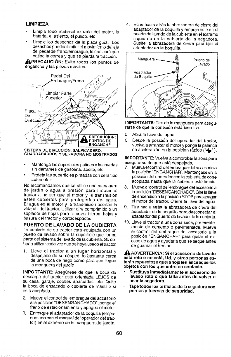
LIMPIEZA
Umpie rode material extrafio del motor, Ia
bateria, el asiento, el pulido, etc.
Limpie los desechos de la placa gui8. Los
desechos pueden limitar et movimiento deI eje
del pedal deI frenolembrague, Io que har& que
patine la correa y que se pierda ta traccion,
_,PREOAUCl6N: Evite todos los puntos de
enganche y las piezas m6viles,
Pedal Dei
j/EmbragueiFreno
/ Limpiar Part,
_ Superior
A
PUNTOS DE
ENGANCHE
S]STEMA DE DIRECCION, SALPICADERO,
GUARDABARROS Y SEGADORA NO MOSTRADOS
Mantenga Ias superficies pulidas y las ruedas
sin derrames de gasolina, aceite, etc,
Proteja Ias superficies pintadas con cera ripe
automotriz.
No recomendamos qua se utilice una manguera
de jardin o agua a presiSn para limpiar el
tractor a no set que el motor y la transmisi6n
esten cubiertos para protegedos de$ agua,
Et agua en el motor y la transmisi6n acortan la
vida 13tiJdel tractor. Utilizar aire comprimido o un
septador de hojas para remover hierba, hojas y
basura det tractor y cortac6spedes.
PUERTO DE LAVADO DE LA CUBIER'[A
La cubierta de su tractor est_ equipada con un
puerto de lavado sobre la supedicie que forma
parte del sistema de 18vado de la cubierta, Se de-
befia utilizar cada vez que se haya usado el tractor.
1. Lleve et tractor a un lugar horizontal y
despejado de su cesped, _o bastante cerca
de una boca de riego come para que Itegue
la manguer8 deI jardin.
IMPORTANTE: AsegQrese de que la boca de
descarga de] tractor est& orientada LEJQS de
su casa, garaie, coches aparcados, etc, Quite
ta boca de ensaca.do o cubierta de mantilIo si
est& acoptad&
2. Mueva el control del embrague deI accesorio
a la position "DESENGANCHADO", ponga el
freno de estacionamiento y apague el motor.
3, Enrosque el adaptador de la boquilla (empa-
quetado con et manual del operador dot trac-
tor) en et extreme de la manguera deI jardJn.
6O
Eche hacia atr&s la abrazadera de cierre del
adaptador de la boquilla y empuje este en el
puerto de tavado de la cubierta en el extreme
izquierdo de ta cubierta de la segadora,
Suelte 18 abrazadera de cierre para fijar et
adaptador en la boquilla.
Puerto de
Lavado
Adaptador
IMPORTANTE: Tire de la manguera para asegu-
rarse de que Ia conexi6n estA bien fiia,
5. Abra la Ilave dei agua.
6. Desde 18 posici6n deI operador del tractor,
vue_va a arrancar e} motor y ponga 18 palanca
de aceleraci6n en Ia posici6n r&pido (",_").
IMPORTANTE: VueIva a comprobar la zona para
asegurarse de que est_ despejada,
7. Muevaet control del embrague del accesorioa
18posici6n "ENGANCHAR". Mantengase en la
posici6n dot operador con Ia cubierta de corte
acoplada hasta qua la cubierta est_ limpia.
8. Mueva ef control del embrague deI accesorio a
la posicion "DESENGANCHADO'L Gire la{lave
de encendido a la posici6n STOP par8 apagar
el motor deI tractor, Cierre la Iiave del agua.
9. Tire hacia arras Ia abrazadera de cierre deI
adaptador de la boquiila para desconectar el
adaptador dei puerto de lavado de I8 cubierta,
10, Lleve el tractor a una zona seca, preferente-
mente de cemento o pavimentada. Mueva
et control del embrague del accesorio a la
posici6n "ENGANCHAR" para quitar el ex-
case de agua y 8yudar a que se seque antes
de guardar et tractor.
_ADVERTENCIA: Si el aceesorio de lavado
estb roto o no esta, Ud. y otras personas es-
tar_n expuestos a q ue la hoja les lance aq uellos
objetos con los que entre en contacto,
• Sustituya inmediatamente el accesofio de
lavado roto o que falta antes de volver a
usar la segadora.
• Tape todos los orificios de 18segadora con
pernos y tuercas de seguridad.
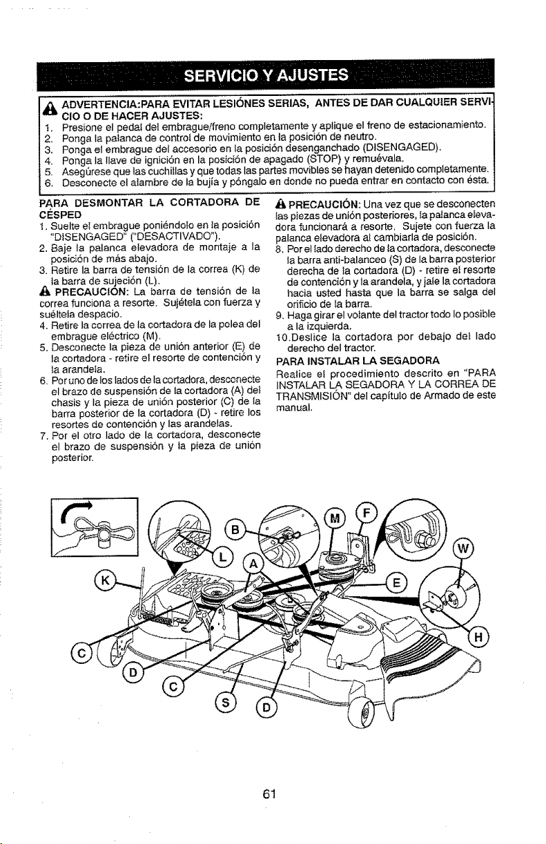
A AOVEm-ENC,A:PARAEVITAR"ES,O.ESSERIAS.ANTESOEDARCU_[QUIERSERV'I
ClO O DE HACER AJUSTES:
t. Presione el peda_ del embrague/freno completamente y aplique el freno de estacionamiento.
2. Ponga Ia paianca de controt de movimiento en ta posiciSn de neutro.
3. Ponga el embrague del accesorio en la posiciSn desenganchado (DISENGAGED).
4. Ponga Ia !lave de ignici6n en la posiciSn de apagado (STOP) y remu@vala.
5. AsegSrese que las cuchitlas y que todas Ias partes movibles se hayan detenido cempletamente.
6. Desconecte el alarnbre de ta bujia y pSngalo en deride no pueda entrar en contacto con @sta.
PARA DESMONTAR LA CORTADORA DE
CE_SPED
t. Suelte el embrague poni_ndo!o en la posici6n
"DISENGAGED" ("DESACTIVADO").
2. Baje la palanca elevadora de montaje a Ia
posici6n de m,_s abajo.
3. Retire la barra de tensi6n de la correa (K) de
]a barra de sujeci6n (L),
PRECAUCtON: La barra de tensi6n de ta
correa funciona a resorte. Suj#tela con fuerza y
suelteia despacio.
4. Retire la correa de la cortadora de la polea del
embrague el_ctrico (M).
5. Desconecte Ia pieza de uniSn anterior (E) de
la cortadora - retire el resorte de contenciSn y
la arandela.
6. Per uno de los Iados de Ia cortadora, desconecte
el braze de suspensiSn de _acortadora (A) del
chasis y la pieza de uni6n posterior (C) de la
barra posterior de la cortadora (D) _ retire los
resortes de contenci6n y las arandelas.
7. Per el otto Iado de la cortadora, desconecte
el braze de suspensiSn y ta pieza de uni6n
posterior.
PRECAUCI6N: Una vez que se desconecten
_as piezas de uni6n posteriores, la palanca eIeva-
dora funcionar& a resorte. Sujete con fuerza Ia
palanca etevadora at cambiarla de posici6n.
8. For el Iado derecho de la cortadora, desconecte
la barra anti-balanceo (S) de la barra posterior
derecha de fa cortadora (D) - retire el resorte
de contenci6n y la arandela, y jaIe la cortadora
hacia usted hasta que la barra se salga deI
odficio de Ia barra.
9. Haga girar el votante deI tractor rode Io posible
a la izquierda.
t0.Deslice la cortadora per debajo de} Iado
derecho deI tractor.
PARA INSTALAR LA SEGADORA
Realice el procedimiento descrito en "PARA
INSTALAR LA SEGADORA Y LA CORREA DE
TRANSMISI6N" del capituto de Armado de este
manual.
61
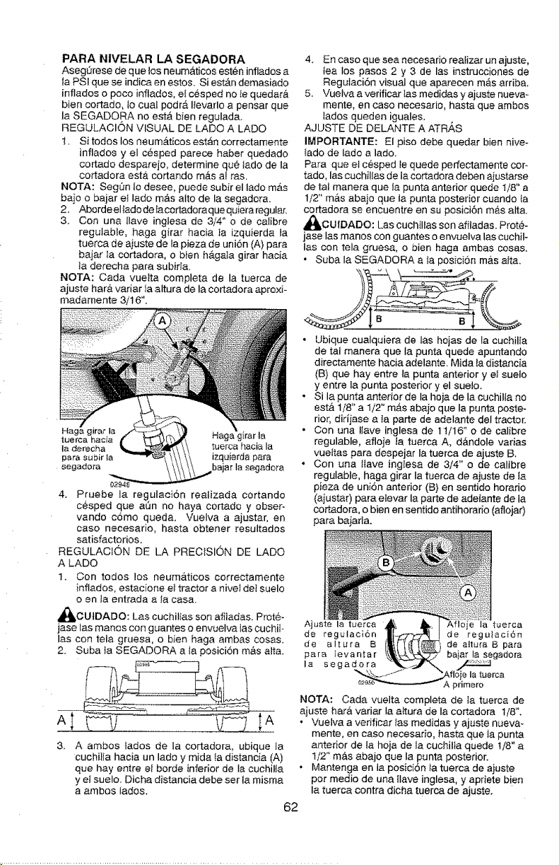
PARA NIVELAR LA SEGADORA
Aseg_rese de que los neum_ticos esten inflados a
Ia PS! que se indica en estos. Si est_tn demasiado
inflados o poco inflados, e_c6sped no te quedar&
bien cortado, Io cua$ podr_. I_evarlo a pensar que
la SEGADORA no esta bien regulada.
REGULAClON VISUAL DE LADO A LADO
1. Si todos los neum&ticos est,_n correctamente
inflados y el c6sped parece haber quedado
cortado desparejo, determine qu6 lado de Ia
cortadora esta cortando m,_s at ras,
NOTA: SegOn Io desee, puede subir el lado m#.s
bajo o bajar et lado mAs alto de la segadora.
2, Aborde elIado de Iacortadoraque quiera regular,
3. Con una Ilave ingtesa de 3/4" o de calibre
regutable, haga girar hacia Ia izquierda la
tuerca de aiuste de la pieza de uni6n (A) para
bajar Ia cortadora, o bien hAgata girar hacia
la derecha para subida.
NOTA: Coda vuetta completa de la tuerca de
ajuste hat& variar Ia altura de la cortadora aproxi-
madamente 3/16",
Haga g
tuerca hacia
|a derecha tuerca hacia la
para subir la izquierda para
segado[a bajar Ia segadora
02948
4. Pruebe la regulaci6n realizada cortando
c6sped que at_n no haya cortado y obser-
vando c6mo queda. Vuelva a ajustar, en
caso necesario, hasta obtener resultados
satisfactorios,
REGULACtON DE LA PRECISION DE LADO
A LADO
1. Con todos los neumaticos correctamente
inflados, estacione ei tractor a nivet dei suelo
o en ta entrada a {a casa.
_bCUtDADO: Los cuchilfas son afiladas. Prote-
jose ins manos con guantes o envuelva los cuchil -
los con tela gruesa, o bien haga ambas cosas.
2. Suba la SEGADQRA a la posicion m&s alta.
A;
A ambos lados de la cortadora, ubique ta
cuchiila hacia un lado y mida la distancia (A)
que hay entre el borde inferior de ia cuchilta
y el suelo. Dicha dJstancia debe set la misma
a ambos lados.
4. En caso que sea necesario reaIizar un ajuste,
tea los pasos 2 y 3 de los instrucciones de
Regulaci6n visual que aparecen m_s arriba.
5. Vuelva a verificar tas medidas y ajuste nueva_
mente, en caso necesario, hasta que ambos
iados queden iguales,
AJUSTE DE DELANTE A ATR,_S
IMPORTANTE: El piso debe quedar bien nive-
tado de iado a lado,
Para queet cesped le quede perfectamente cor m
tado, las cuchil_as de Ia cortadora deben aiustarse
de tai manera que la punta anterior quede 1/8" a
1/2" m&s abajo que Ia punta posterior cuando la
cortadora se encuentre en su posici6n mb,s alta.
_IbCUIDADO: Los cuchillas son affladas. Prot@-
jase Ins manos con guantes o envuelva los cuchiI-
Ins con tela gruesa, o bien haga ambas cosas.
• Suba Ia SEGADORA a la posici6n m&s attn.
• Ubique cualquiera de los hojas de Ia cuchilia
de tal manera que Ia punta quede apuntando
directamente hacia adelante. Mida ta distancia
(B) que hay entre la punta anterior y et sueio
y entre la punta posterior y el suelo.
• Sila punta anterior de Ia hoja de la cuchilta no
est& 1/8" a 1/2" mb.s abajo que Ia punta poste-
rior, dirijase a Ia parte de adelante deI tractor.
• Con una IIave inglesa de 1!/16" o de calibre
regulable, afloje ia tuerca A, d&ndole varias
vueltas para despejar Ia tuerca de ajuste B,
• Con una ttave ingIesa de 3/4" o de calibre
regulable, haga girar Ia tuerca de ajuste de la
pieza de uni6n anterior (B) en sentido horatio
(ajustar) para elevar la porte de adelante de ia
cortadora, o bien en sentido antihorario (aflojar)
para baiada.
Ajuste la tuerca uerca
de regulaci6n de regu}aciSn
de aI_ura B de a!tura B para
Faro _evantar baiar la segadora
la segadora
_"_'_-_J-J j'Afloje Iatu*' " erca
02asc,_ A primero
NOTA: Cada vuelta completa de ]a tuerca de
ajuste hat& variar Ia attura de Ia cortadora 1/8 '_,
• Vuelva a verificar Ins medidas y ajuste nueva_
mente, en caso necesario, hasta que ta punta
anterior de la hoja de la cuchilta quede t/8" a
1/2" m&s abajo que la punta posterior.
• Mantenga en ia posid6n ta tuerca de ajuste
por medio de una flave inglesa, y apriete bien
la tuerca contra dicha tuerca de ajuste.
62
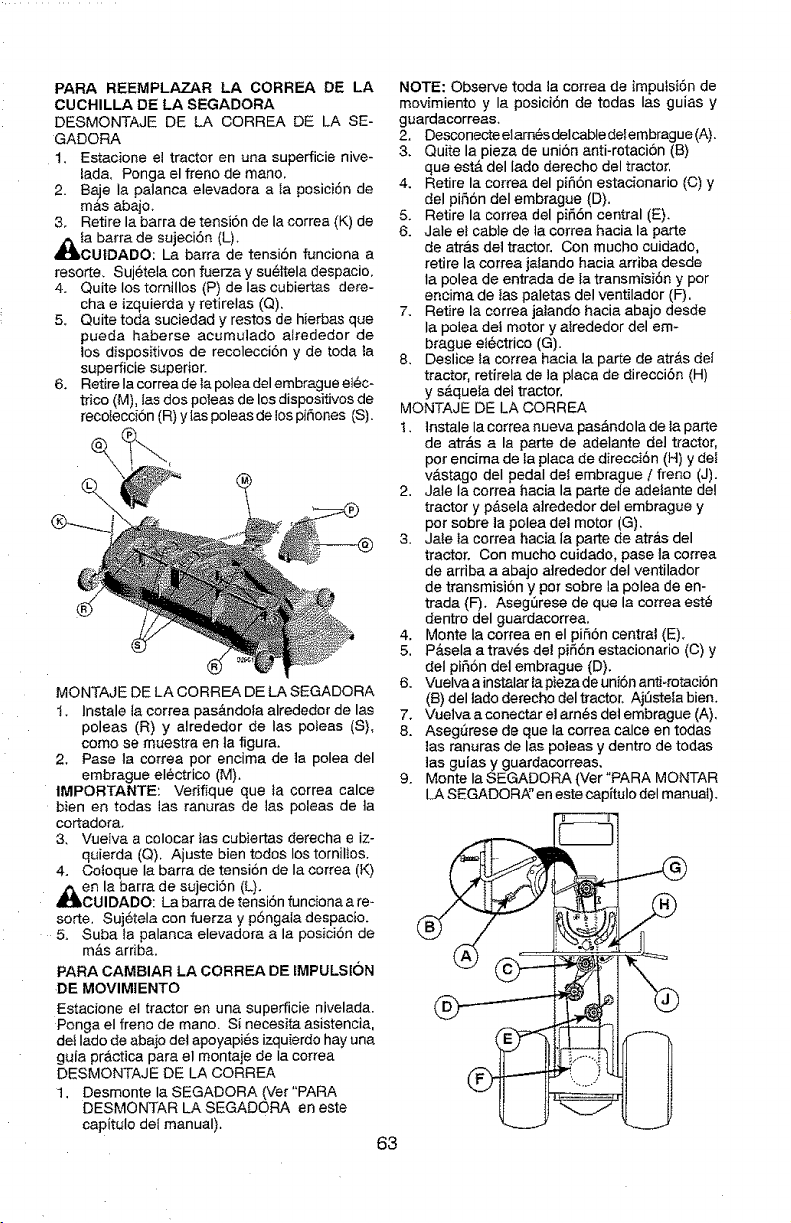
PARA REEMPLAZAR LA CORREA DE LA
CUCHILLA DE LA SEGADORA
DESMONTAJE DE LA CORREA DE LA SE-
GADORA
1, Estacione el tractor en una superficie nive-
lada, Ponga el freno de mane.
2. Baje Ia patanca elevadora a Ia posici6n de
m,Cs abajo.
3. Retire la barra de tensi6n de la correa (K) de
,_lLia barra de sujeci6n (L).
CUtDADO: La barra de tensi6n funciona a
resorte. Sujetela con fuerza y su_ltela despacio.
4. Quite los tomillos (P) de Ias cubiertas dere-
cha e izquierda y retirelas (Q).
5. Quite toda suciedad y restos de hierbas que
pueda haberse acumulado airededor de
los dispositivos de recolecci6n y de toda ta
superficie superior.
6. Retire Ia correa de Ia poleadel embrague el@c-
trice (M). tas dos poleas de los dispositivos de
recotecci6n (R) y [as poleas de los pifiones (S).
MONTAJE DE LA CORREA DE LA SEGADORA
t. Instale la correa pas&ndota alrededor de las
poleas (R) y alrededor de Ias poteas (S),
come se muestra en la figura.
2. Pase la correa per encima de la polea del
embrague eI6ctrico (M).
IMPORTANTE: Verifique qua ta correa calce
bienen todas las ranuras de las poleas de ta
cortadora.
3. Vueiva a colocar tas cubiertas derecha e iz-
quierda (Q). Ajuste bien redes los tornillos.
4. Cotoque Ia barra de tensi6n de Ia correa (K)
41_en la barra de sujeci6n (L}.
CUll)ADO: La barra de tensiSn funciona a re-
sorte. Suj6tela con fuerza y p6ngala despacio.
5. Suba la palanca elevadora a la posiciSn de
m&s ardba.
PARA CAMBIAR LA CORREA DE IMPULSION
DE MOVIMIENTO
Estacione el tractor en una superficie nivelada.
Ponga el franc de mane. Si necesita asistencia.
det Iado de abajo det apoyapies izquierdo hay una
guia practica para el montaje de Ia correa
DESMONTAJE DE LA CORREA
1. Desmonte Ia SEGADORA (Ver"PARA
DESMQNTAR LA SEGADORA en este
capitulo dei manual).
63
NOTE: Observe toda ta correa de imputsi6n de
movimiento y la posici6n de tedas Ias guias y
guardacorreas.
2. Desconecte elam_s delcable delembrague (A).
3. Quite la pieza de uni6n anti-rotaci6n (B)
que estA del lade derecho del tractor,
4. Retire la correa del pifi6n estacionario (C) y
del pi56n deI embrague (D).
5. Retire la correa del pifi6n central (E).
6. Jale e! cable de ta correa hacia la parte
de arras del tractor. Con touche cuidado,
retire la correa jalando hacia arriba desda
Ia polea de entrada de la transmisi6n y per
encima de fas paletas del ventilador (F).
7. Retire la correa jalando hacia abajo desde
Ia polea det motor y alrededor del em*
brague eI6ctrico (G).
8. Deslice la correa hacia la parte de atr&s del
tractor, retirela de la placa de direcci6n (H)
y s&quela det tractor.
MONTAJE DE LA OORREA
1. lnstale Ia correa nueva pas&ndola de ta parte
de atr&s a la parte de adelante del tractor,
per encima de fa placa de direcd6n (H) y dei
vastago deI pedal del embrague / freno (J).
2. Jale la correa hacia la parte de adelante del
tractor y p_.sela alrededor deI embrague y
per sobre la polea del motor (G).
3. Jaie Ia correa hacia la parte de atr&s del
tractor. Con mucho cuidado, pase ta correa
de arriba a abajo airededor del ventilador
de transmisiSn y per sobre la polea de en-
trada (F). Aseg0rese de que la correa est@
dentro del guardacorrea.
4. Monte la correa en el pifi6n central (E).
5. P&sela a traves del pifi6n estacionario (C) y
deI pifi6n del embrague (D).
6. Vuelva a instalar la pieza de uni6n anfl-rotaci6n
(B)del tado derecho del tractor. Aj0stela bien.
7. Vuelva aconectar el am6s del embrague (A).
8. AsegSrese de que Ia correa calce en todas
las ranuras de las poleas y dentro de todas
]as guias y guardacorreas.
9. Monte la SEGADORA (Ver"PARA MONTAR
LA SEGADORA ° en este capltulo del manual).
@_____---
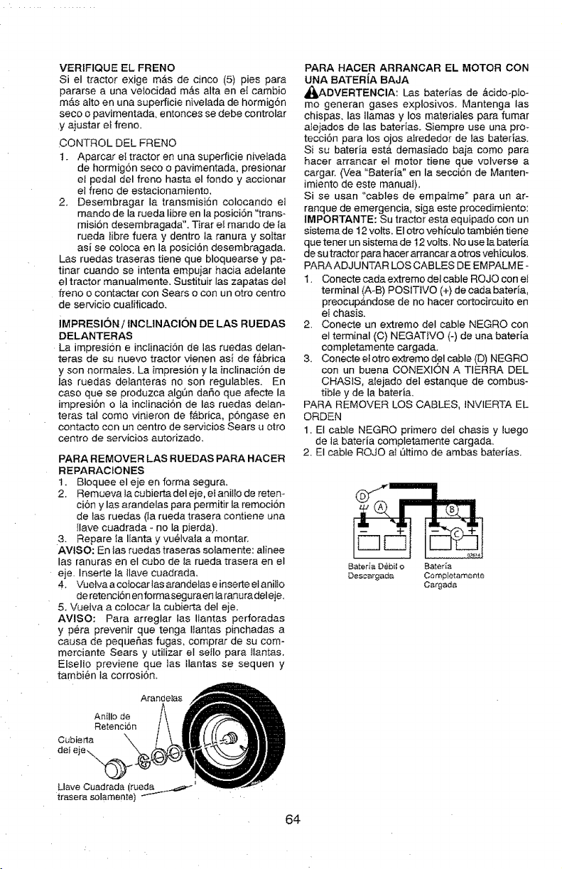
VERtFIQUE EL. FRENO
Si el tractor exige mas de cinco (5) pies para
pararse a una ve_ocidad m_.s alta en el cambio
m&s alto en una superficie nivelada de hormig6n
seco o pavimentada, entonces se debe controlar
y aiustar e_ freno.
CONTROL DEL FRENO
1. Aparcar eI tractor en una superficie nivelada
de hormig6n seco o pavimentada, presionar
el pedal del freno hasta el rondo y accionar
el freno de estacionamiento,
2. Desembragar la transmisi6n colocando el
mando de Ia rueda Iibre en la posici6n "trans-
mision desembragada". Tirar el mando de Ia
rueda }ibre fuera y dentro ta ranura y so}tar
asi se cofoca en la posicion desembragada,
Las ruedas traseras tiene que bloquearse y pa-
tinar cuando se intenta empuiar hacia adelante
el tractor manualmente. Sustituir las zapatas deI
freno o contactar con Seats o con un otto centre
de servicio cualfficado.
iMPRESION / {NCLINACI6N DE LAS RUEDAS
DELANTERAS
La impresi6n e incJinaci6n de las ruedas delan-
teras de su nuevo tractor vienen asi de f&brica
y son normaies. La }mpresi6n y la inctinaci6n de
las ruedas delanteras no son regulabIes. En
caso que se produzca algt3n daSo que afecte la
impresi6n o la inclinaci6n de las ruedas delan-
teras tal como vinieron de fa.brica, p6ngase en
contacto con un centro de servicios Sears u otto
centro de servicios autorizado.
PARA REMOVER LAS RUEDAS PARA HACER
REPARACfONES
1. Bloquee el eje en forma segura,
2. Remueva ta cubierta del eje, el aniilo de retem
cion y las arandelas para permitir la remoci6n
de las ruedas (la rueda trasera contiene uaa
Ilave cuadrada - no Ia pierda).
3. Repare _a Iianta y vu@Iva}a a montar.
AVtSO: En tas ruedas traseras soIamente: alinee
las ranuras en el cubo de ta rueda trasera en el
eje. Inserte ta llave cuadrada,
4, Vuelva a cotocar las arandelas e inserte el aniIIo
de retenciSn en formaseguraen ta ranuradeleje,
5. Vuelva a colocar Ia cubierta del eje.
AVlSO: Para arreglar las Ilantas perforadas
y pera prevenir que tenga #antas pinchadas a
causa de pequer'_as fugas, comprar de su com-
merciante Sears y utilizar el seIIo para llantas,
Etsello previene que las tlantas se sequen y
tambien Ia corrosi6n.
Arandetas
Anillo de
Retenci6n
Cubierla "-,
dell"
PARA HACER ARRANCAR EL MOTOR CON
UNA BATERIA BAJA
_ADVERTENCIA: Las baterias de &cido-plo =
mo generan gases explosivos. Mantenga las
chispas, las llamas y los materiales para fumar
alejados de las baterias. Siempre use una pro_
tecci6n para los ojos alrededor de fas baterias.
Si su bateda est& demasiado baja como para
hacer arrancar el motor tiene que volverse a
cargar. (Vea "Bateria" en la seccion de Manten-
imiento de este manual),
Si se usan "cables de empatme" para un ar-
ranque de emergencia, siga este procedimiento:
IMPORTANTE: Su tractor esta equipado con un
sistema de 12 volts. El otro vehiculo tambien tiene
que tenet un sistema de t2 volts. No use }a bateria
de su tractor para hacer arrancar a otros vehiculos.
PARA ADJ U NTAR LOS CAB LES DE EMPALM E -
1. Conecte cada extremo del cable ROJO con et
terminal (A-B) POSITIVO (+) de cada bateria,
preocup&ndose de no hacer cortocircuito en
el chasis.
2. Conecte un extremo del cable NEGRO con
el terminal (C) NEGATtVO (-) de una bateria
completamente cargada.
3. Conecte el otto extremo d el cable (D) NEGRO
con un buena CONEXION A TERRA DEL
CHAStS, alejado del estanque de combus-
tible y de la bateria.
PARA REMOVER LOS CABLES, INVIERTA EL
ORDEN
1. El cable NEGRO primero del chasis y luego
de la bateria completamente cargada,
2. El cable ROJO ai _}timo de ambas baterias.
Bater_aDebit o Bater[a
Desca_gada Cempletamen_e
Cargada
Llave Cuadrada (ruede .._ _
trasera solamen_e)
64
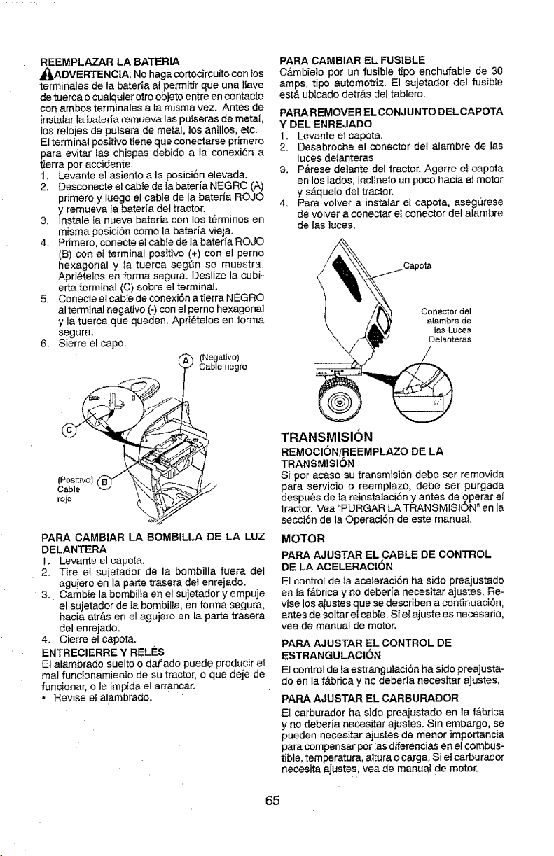
REEMPLAZAR LA BATERIA
_ADVERTENCIA: No haga cortocircuito con los
terminales de Ia bateda at permitir que una liave
de tuerca o cualquier otroobjeto entre en contacto
con ambos terminales a la misma vez. Antes de
[nstalarla bateria remueva los pulseras de metal,
los relojes de pulsera de metal, los anilIos, etc.
El terminal positive tiene que conectarse primero
para evitar las chispas debido a Ia conexiSn a
tierra per accidente,
1. Levante el asiento a la posiciSn elevada.
2. Desconecte e_cabte de Ia baterla NEGRO (A)
primero y luego el cable de la bateda ROJO
y remueva ta bateda deI tractor.
3. Instale la nueva bateria con los t6rminos en
misma posici6n come la bateria vieja.
4. Primero, conecte et cable de la bateria ROJO
(B) con ei terminal positive (+) con el perno
hexagonal y la tuerca segSn se muestra.
Apri_telos en ferma segura. Deslize la cubi-
erta terminal (C) sobre el terminal.
5. Conecte el cable de conexi6n a tierra NEGRO
al terminal negative (-) con el perno hexagonal
y Ia tuerca que queden, Apri@telos en forma
segura.
6, Sierre el cape.
(Negative)
Cablenegro
PARA CAMBIAR EL FUSIBLE
CAmbieto per un fusible tipo enchufable de 30
amps, tipo automotnz. El sujetador deI fusible
est& ubicado detr&s deI tablero.
PAPA REMOVER EL CONJ UNTO D EL CAPOTA
Y DEL ENREJADO
1, Levante el capota,
2. Desabroche el conector de] alambre de los
luces deIanteras,
3. P&rese de]ante del tractor. Agarre e_capota
en los Iados, inclineto un poco hacia el motor
y s_.quelo del tractor.
4, Para volver a instalar el capota, aseg_rese
de volver a conectar el conector deI alambre
de las ]aces.
(Positive)
Cable
roje
PARA CAMBIAR LA BOMBILLA DE LA LUZ
DELANTERA
t. Levante el capota.
2. Tire eI sujetador de la bombilla fuera deI
agujero en Ia portetrasera del enrejado.
3. Cambie la bombilfa en el sujetador y empuje
el sujetador de fa bombilta, en forma segura,
hacia atrAs en el agujero en la porte trasera
del enrejado,
4, Cierre et capota.
ENTRECIERRE Y RELIES
El alambrado suelto o dahado puede producire]
maI funcionamiento de su tractor, o que deje de
funcionar, o Ie impida el arrancar.
• Revise el alambrado.
TRANSMISION
REMOCIONiREEMPLAZO DE LA
TRANSMISION
Si per acaso su transmisi6n debe ser removida
para servicio o reemplazo_ debe ser purgada
despues de ta reinstataci6n y antes de operar el
tractor. Vea "PURGAR LA TRANSMISION" en la
secciSn de la Operaci6n de este manual
MOTOR
PARA AJUSTAR EL CABLE DE CONTROL
DE LA ACELERACtON
Et control de la aceIeraci6n ha side preajustado
en Ia f&brica y no deberia necesitar ajastes. Re-
vise los aiustes que se describen a continuaci6n,
antes de soltar el cable, Si el ajuste es necesario,
vea de manual de motor,
PARA AJUSTAR EL CONTROL DE
ESTRANGULACION
El control de ta estrangu]aci6n ha side preajusta-
do en la f&brica y no deberia necesitar ajustes.
PARA AJUSTAR EL CARBURADOR
El carburador ha side preajustado en la fdbrica
y no deber[a necesitar ajustes. Sin embargo, se
pueden necesitar ajustes de menor importancia
para compensar per las difereneias en el combus-
tible, temperatura, altura o cargo. Si el carburador
necesita ajustes, yea de manual de motor.
65
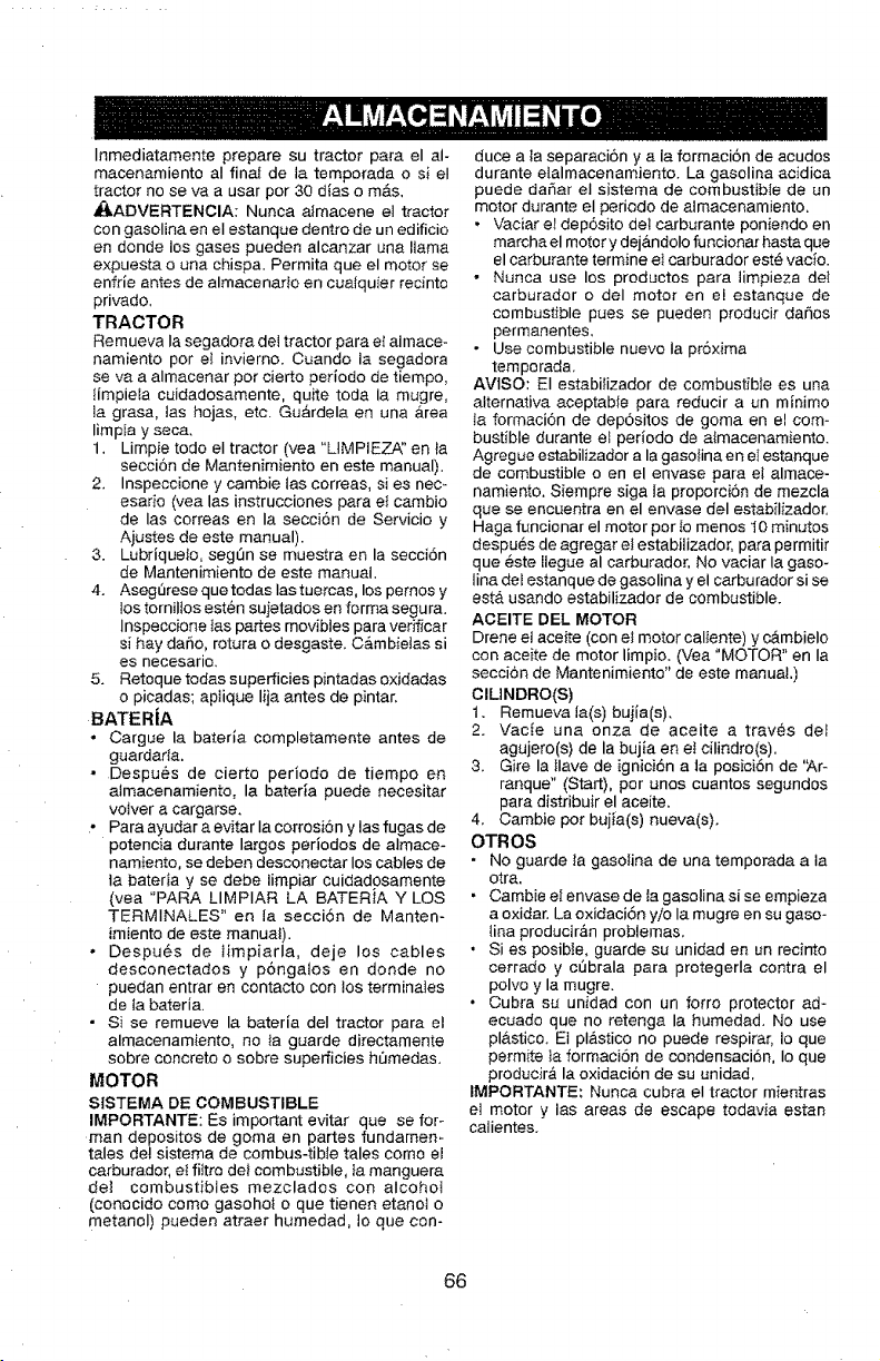
Inmediatamente prepare su tractor para el al-
macenamiento aI finaf de ia temporada o si el
tractor no se va a usar per 30 dias o m&s,
_ADVERTENCIA: Nunca almacene el tractor
con gaselina en el estanque dentro de un edificio
en donde los gases pueden alcanzar una llama
expuesta o una chispa. Permita que el motor se
enfrle antes de almacenarto en cualquier rednto
privado.
TRACTOR
Remueva Ia segadora deJ tractor para et aimace-
namiento per el invierno. Cuando ia segadora
se va a almacenar per cierto periodo de tiempo,
IimpieIa cuidadosamente, quite toda la mugre,
la grasa, Ias hojas, etc. Gu&rdela en una &rea
limpia y seca,
1. Limpie todo el tractor (vea "LIMPIEZA" en _a
secci6n de Mantenimiento en este manual),
2. Inspeccione y cambie ias correas, si es nec-
esarie (yea las instrucciones para et cambio
de las correas en la secci6n de Servicio y
Aiustes de este manual).
3. Lubriquelo, segSn se muestra en la secci6n
de Mantenimiento de este manual.
4. Asegt3rese que todas Ias tuercas, los pemos y
los tornilios esten suietados en forma segura.
Inspeccione tas partes movibles para verificar
si hay dar_o, rotura o desgaste. C&mbielas si
es necesario.
5. Retoque todas superficies pintadas oxidadas
o picadas; aplique lija antes de pintar,
BATERJA
° Cargue la baterla completamente antes de
guardada.
- Despu6s de cierto periodo de tiempo en
almacenamiento, la bateria puede necesitar
volver a cargarse.
• Para ayudar a evitar Ia corrosi6n y las fugas de
potancia durante largos periodos de almace-
namiento, se deben desconectar los cables de
ta bateria y se debe iimpiar cuidadosamente
(vea "PARA LIMPIAR LA BATERtA Y LOS
TERMINALES" en Ja secci6n de Manten-
imiento de este manual).
, Despu6s de iimpiarla, deje los cables
desconectados y p6ngalos en deride no
puedan entrar en contacto con los terminaies
de la bateria.
• Si se remueve la bateria deI tractor para et
almacenamiento, no la guarde directamente
sobre concrete o sobre superficies h_medas.
MOTOR
StSTEMA DE COMBUSTIBLE
IMPORTANTE: Es important evitar que se for_
man depositos de goma en partes fundamem
tales det sistema de combus-tible tales come el
carburador, ei fiitro def combustible, }a manguera
det combustibles mezclados con alcohot
(conocido come gasohol o que tienen etanot o
metaneI) pueden atraer humedad, Io que con-
duce a la separaci6n y a la formaci6n de acudos
durante etalmacenamiento. La gasolina acidica
puede daSar el sistema de combustible de un
motor durante el periodo de almacenamiento.
• Vaciar eI dep6sito det carburante poniendo en
marcha el motor y dej&ndolo funcionar hasta que
el carburante termine el carburador est6 vac_o.
• Nunca use los productos para limpieza del
carburador odel motor en el estanque de
combustible pues se pueden producir daSos
permanentes.
• Use combustible nuevo ia pr6xima
temporada.
AVIS0: El estabifizador de combustible es una
alternativa aceptable para reducir a un minimo
Ia formaci6n de depositos de goma en el com-
bustible durante et perlodo de atmacenamiento.
Agregue estabilizador a la gasolina en el estanque
de combustible o en el envase para et almace-
namiento. Siempre siga Ia proporci6n de mezcla
que se encuentra en el envase del estabilizador.
Haga funcionar el motor per to menos 10 minutes
despu6s de agregar el estabilizador, para permitir
que _ste llegue al carburador. No vaciar la gaso-
iina del estanque de gasolina y el carburador si se
est& usando estabilizador de combustible.
ACEITE DEL MOTOR
Drene el aceite (con el motor caliente) y c&mbielo
con aceite de motor limpio. (Vea "MOTOR" en Ia
secci6n de Mantenimiento" de este manual.)
ClLINDRO(S)
1, Remueva la(s) bujia(s ),
2. Vacie una onza de aceite a traves del
agujero(s) de la bujia en et cilindro(s),
3. Gire la llave de ignici6n a la posici6n de 'Ar-
ranque" (Start), per unos cuantos segundos
para distribuir el aceite.
4, Cambie per bujia(s) nueva(s),
OTROS
. No guarde la gasotina de una temporada a ta
otra.
• Cambie el envase de la gasolina si se empieza
a oxidar. La oxidaci6n yio la mugre en su gaso-
lina producir_n problemas.
, Si es posibte, guarde su unidad en un recinto
cerrado y c0brala para protegerla contra el
polvo y la mugre.
• Cubra su unidad con un forte protector ad-
ecuado que no retenga la humedad. No use
pl&stico. El plastico no puede respirar, Io que
permite }a formacibn de condensaci6n, Io que
producira la oxidaci6n de su unidad.
IMPORTANTE: Nunca cubra el tractor mientras
el motor y ias areas de escape todavia estan
calientes,
66
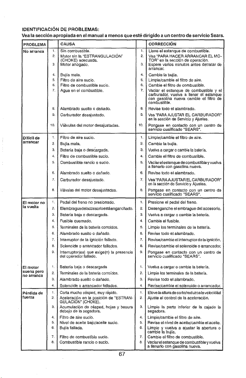
IDENTIFICACION DE PROBLEMAS:
Vea la seccibn apropiada en el manual a menos que est_ dirigido a un centre de servicio Sears.
PROBLEMA
NO artanca
Dific|t de
arrancar
E! motor no
ta vuelta
Et motor
suel3e pore
no erranca
P_rdida de
f uer'za
CAUSA
_. Sin combustibiel .........
2 Motor sin ta "ESTRANGULACiON"
(CHOKE) adecuada.
3 Motor ahogado,
4, Bujia mala.
5 Filtro de a}re sucio.
6, Filtre de combustible sucie,
7, Aguaen el combustible,
8. Alambrado suelte o dahado,
9. Carburador desajustado.
10. V&lvulas del motor desajustadas,
l Filtro de aire sucio.
2 Buiia mala.
3, Bateria baja o desc'argada,
4, Filtro de combustible sucio,
5 Combustible rancio o sucio,
& A[ambrado suelto o daSado.
7. Carburador desajustado.
8 Valvu[es del motor desajustadas,
1_ Pedal deifreno no presionado.
2, Elembraguedeeaecesor;oest&enganchado,
3, Bateda baja e deseargada.
4, Fusible quemedo.
5. Terminalesde Ia baterla correidos,
6, Alambrado sueltoo da_ado.
7, {nterruptor de la ignici6n fee}ado.
8, Solenoide o arrancador falI_dos.
9, interrupter(as) qoe exige(n) la presencia
deI operador fallado.
7 Beteria ba}a o descargada
2, Termina}es de la bateria corroidos.
3. AIambrade suelto o da#,ade.
4. Solenoide, o, arrancador falledos. , ......
1. Corta touche c_.sped, muy r&pido,
2. Aceterac{.6n en {a posici6n de "ESTRAN-
GULACION" (CHOKE).
3. Acumulaci6n de cesped, hojas y basura
debaio de la segadore.
4. Fittro de aire sucio,
5. NiveI de ace{re bajeiaceite sucie,
6. Buiia faUada,
7, Filtro de combustible sucio,
8. Combustible rancie o sucio,
CORRECCION
'L Llano Jestanque de
co'mbustibl'el
2, Vea "PARA HACER ARRANCAR EL MO-
TOR" en ia secci6n de eperaci6n.
3, Espere varies minutes antes detratar de
arrancar.
4, Cambie la buj{a.
5. Limpieicambie el filtro de aire,
6. Oambie el filtro de combustible.
?. Vacier et estanque de combustible y el
carburador, vuelva a Ilenar el estanque
con gasolir_a nueva cambie et filtro de
combustible,
e, Revise todo el alambrado.
9, Vea ?ARA AJUSTAR EL CARBURADOR"
en la secci6n de Servicio y Ajustes,
10. Pon£ase en contaoto con un centre de
serv_cio cual_cado "SEARS",
1, Limp_eicambie el filtro de aire.
2. Cambie la bujfa.
3. Vuelva acargar o cambie Ia bated&
4. Cambie el filtro de combustible,
S. Vacier el estanque de combustible yvuelva
a Ilenarlo co_ gasoline nueva,
6, Revise todo el a_ambrado.
7, Vea"PARA AJUSTAR EL OARBURADOR"
en _asecci6nde Sewici0 y Ajustes.
8, Pongase en contacto con un centre de
servicio cualificado "SEARS".
, ,, ,,....... ,
1, Presio,qe el pedal deI freno.
2. DesengancheeIembraguedeIeccesorio.
3 Vuelva a cergar o cambie Ia bated&
4 Cambie el fusible.
& Limpie los terminales de la bateria,
& Revise rode e_alambrado,
7. Reviseicambie et interruptorde la igniciSn.
8, Revise,icambie et soteneide o arrancador,
9, Pongase ea contacto con un centre de
setvlc_o cua]ificado "SEARS",
1, Vuelva a cargar o cambie Ia bateria,
2. Limpie los terminales de la beteda,
3. Revise todo e] aiambrado,
4. Revise/cembie el soIenoide 0 arrancador,
1. Eleveta altura,de corte/reduzea la velocidad
2. Ajuste el controI de Ia aceleraci6n,
& Limpie Ia parte infer_or de la cajade ta
segadora,
4. Limpieicambie el filtro de aire.
5, Revise el n_velde aceite/cambie el aceite,
6, Limpie y vuelva a ajustar la eber_ura o
cambie {a bujie_.
7, Cambie el f}{tro de combustible,
8 Vaciar elestanque de combustiNe y vuelva
a I{enarlo con gasoline nueva.
67
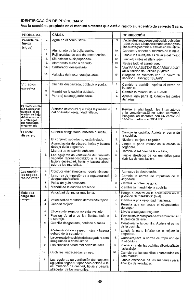
IDENTtFtCACION DE PROBLEMAS:
Vea la seccion apropiada en el manual a menos que est_ dirigido a un centre de servicio Sears.
PROBLEMA CAUSA
P_rdida de 9, Agua en elcombastible. '....
fuerza
(sigue}
10. Alambrado de ;a bu[ia suelto,
11, ReiilLa/aletas de aire de4 motor sucias,
12. Sitenciado r sucio/tapo nado.
13. Alambrado suello o dafiado.
14. Carbutador desajuslado,
15, V_.lvulas del motor desajustadas,
Vibraci6n 1. Cuchil]a desgastada, deblada o suefta.
excestva
2. Mandril de Ia cachilta doblado.
3, Parts(s) suelta(s)idai_ada(s).
Ei meter coati,
n_afuncion_ndo
cuando el op-
erador se baja
de{asientocon
el embr_gue
del acc'esorio
enganchado
El torte
disparejo
CORRECCION
9, Vaciare'i'estanque de cornbusti'bte yelcarbu.
radar, vueiva a Ilenarel estanquecongasoo
Iina nueva y cambie eIfi{tro de co mbustib}e,
t0. Conecte y apdete el alambre de la buiia.
1"L Limpie Ias rejJllaialetas de aire del motel
42, Limpieicambie el s[lenciador.
_3, Revise lode elalambrado.
14. Vea"PARA AJUSTAR EL CARBU RAD OR"
en ia secc[6n de Sercicio y Ajustes.
t5. Pongase en contacto con un centre de
servicio cualificado "SEARS",
1. Cambie la cuchilia, Apdete el perno de
la cuchiIIa.
2. Cambie la mandril de la cuchilIa.
3. Apdete la(s) parle(s). Cambie _as partes
dar3adas.
Sistema de control que exige ta presencia
deI operador -seguddad faItado,
Revise el alambrade, los interruptores
y la conexiones.Si no est&n correctas
Pongase er_ contacto con un centre de
servicio cualificado "SEARS".
1, Ouehilla desgastada, dobtada esuelta.
2. El conjunto segador no est#,nive_ado.
& AcumuiaciSn de c6sped, holes y basura
debaio de Ia segadora,
4. Mandril de la cuchii_a dablado.
5, Los agujeros de ventJIaci6n deI coniunlo
segador laponadosdebido ala acumu=
lacf6n dec6_sped, hojas y basura aired-
edorde los mandriles.
...............t i,,,.....
Lae cuchil- 1. Obstrucci6nenelmecanismodelembrague,
}las segade- 2. Lacorreade impulsiSn de la segadora est8
ras no reran desgastedaidafiadao
3. Pelea de guia atascada.
4. Mandril de lacuchilla atascado,
..........,,,,,,, .......
1, Veiacidad del motor muy lento,
Mala des_
carga del
cbsped 2,
3,
4.
5.
&
7
&
9.
t0,
1t.
VeIocidad de _corrido demasiador_pida,
C6sped mojado.
El coniunte segador no est&nivelado.
Presi6n de airs de Ins Ifantas baja o
dispareja.
Cuchilla desgastada, deblada o suetla,
Acumulaci6n de cesped, hojas y basura
debajo de {a segadora.
Lacorreade impulsi6n de IasegadoraestA
desgastada o desaiustada.
Las cuchillas est&n maI coninslaladas.
Cuchillas inadecuadas en use.
Los agujeros de ventilaci6n de{ conjunto 11,
aguieros segador taponados debido ala
acumulaci6n de c_sped, hoias ¥ basura
alrededar de as mandriles,,,
t. Cambie {a cuchiIIa. Apriete el perno de
la cuchilla.
2, Nivele el conjunlo segador.
3. Limpie la pa_e inferior de la caiade {a
segadora,
4. Cambie }a mandriide la cuchilla,
5. Limpie atrededor de los mandriles pare
abrir los de ventilaci6n.
Remueva la obstruccion.
2, Cambie ia correa de impulsiSn de {a
segadora,
3 Cambie la poise de guia.
4, Cambie Ia mandd{de Ia cuchilla,
Ponlg.' at_ontrode,_aoe,_aoi6_en,a
1,
poslclon de "RAPIDO" (fast).
2. Cambie a una velocidad m&s lento.
3, Permita que se seque el cespedantes
de segar.
4 Nivele el conjunto segador.
& Revise ias_tantas para verificarque tienen
la presi6n de a[re,
6, Cambie/afile la cuchilla, Apriete el pemo
de ta cuchilla.
7. Limpie la parle inferior de la caiade la
segadora,
8 Cambieiajuste {a correa de impulsiSn de
la segadora,
e. Vuelva a inslalar Ins cuchiIias elbords afiJado
hacia abajo.
_o. Cambie per los cuchilias enumeredas en
este manual.
Limpie alrededor de los mandriles pare
abrir los de ventilaci6n.
68
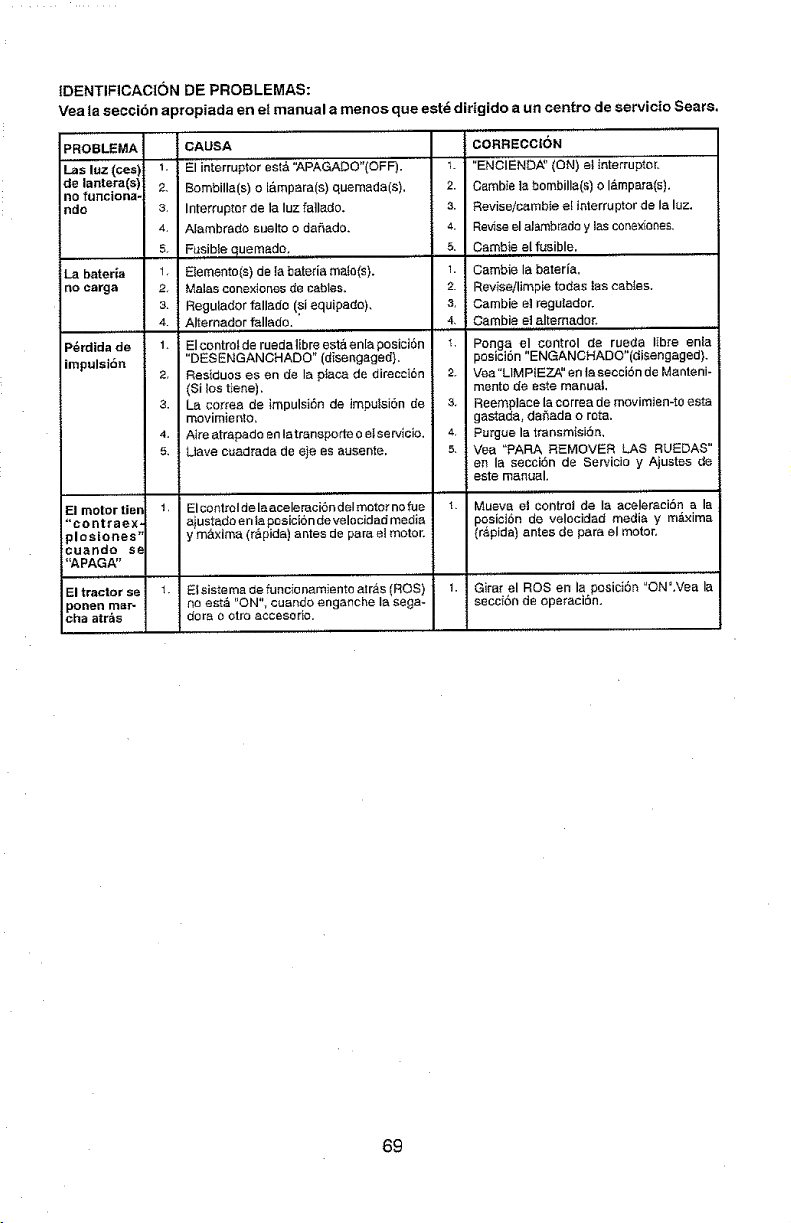
IDENTIFICACtON DE PROBLEMAS:
Vea ta seccion apropiada en e! manual a manes que est_ diHgido a un centre de se_'vicioSears,
PROBLEMA CAUSA
I_as luz (ces) 1'.' El interrupior' est& '_PAGADO"(OFF). 1'_'
de lantera(s) 2, Bombilla(s) o l_.mpara(s) quemada(s). 2.
no funciona-
ndo 3, Interrupter de la Iuz fatlado, 3.
4, Alambrado suelto o dafiado, 4.
5. Fusibfe quemade, 5,
La bateria 1 Eiemento(s) de [a bateria maJo(s). 1.
no carga 2 Malas conexiones de cables, 2,
3. Regutador fallade (si equipado), &
4. Alternador fallado. 4,
P_rdida de 1. EIcontrolde ruedalEbre estaenlaposici6n 4.
impulsidn "DESENGANCHADO" (disengaged).
2, Residues es en de Ia p_aca de direcci6n 2.
(Si los tiene).
3. la correa de impulsi6n de impuisiSn de &
movimiento,
4, Aire atrapado en Iatransporte 0 elservicio. 4.
5. Uave cuadrada de eje es ausente, 5.
..... , ,, ,,
El motortien 1, Elcontroldelaaceleraci6ndelmetornofue 1,
"co ntra ex, ajustada en tapesici6n develocidad media
plestones" y m&×ima (r&pida) antes de para el motor.
cuando se
"APAGA"
El tractor se 1, Eisistema de funcienamiente atr&s (ROS) 1.
no est& "ON", cuando enganche Ia sega-
ponen mar-
cha atr_s dora 0 otro accesorio,
CO_RECCI_N
"ENOIEND/_' (0Ni'"eI interrupter,
Cambie la bombilia(s) o I&mpara(s),
Revise/oambie el interrupter de la luz,
Rev;seel alambrado y las cone×iones.
Cambie el fusible.
..... ,,,,,,
Cambie Ia bateria,
Reviseilimpie todas las cables.
Cambie el regufadoro
Cambie el altemador.
Ponga el control de rueda libre enla
posiciSn "ENGANOHADO"(disengaged).
Vea"LIM PtEZA" en lasecciSn de Manteni-
monte de este manual,
Reemplace la correa de movimien-to esta
gastada, daf_ada o rata.
Purgue la transmisiSn,
Vea "PARA REMOVER LAS RUEDAS"
en la secci6n de Setvicio y Ajustes de
este manual,
Mueva el control de Ia aceIeraci6n a la
posici6n de velocidad media y m_xima
(r_pida) antes de para el motor,
Gira_ el ROS en laoposiciSn "ON",Vea Ia
seccion de operaclon,
69

70
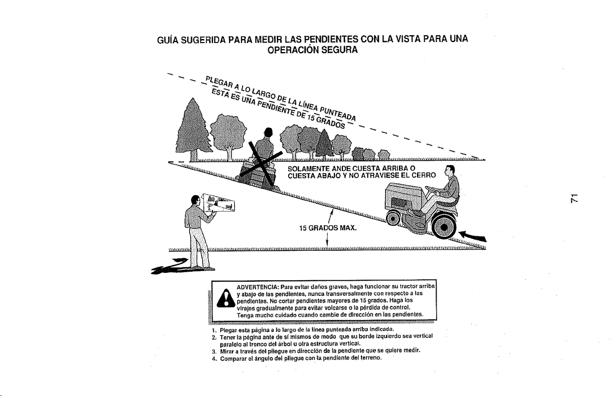
GUiA SUGERIDAPARA MEDIRLAS PENDIENTESCON LA VISTA PARAUNA
OPERACIONSEGURA
t
ADVERTENCIA: Para evitar daSos graves_ haga funclonar su tractor arrJbal
_y abaio de las pendientes_ nunca transversaImente con respec_:oalas
_u_ pendlentes, No cortar pendiantes mayores de t5 gradoso Haga los |
vlrajes gradualmente para evitar volc_rse o la pdrdida de control, l
Tenga mucho cuidado cuando cambie de direccI6n en Ias pendientes. |
t. Plegar esta pdgina a Io largo de la l_nea punteada arriba _ndlcada.
2, Tener la p,_gina ante de s{ mismos de modo qua su borde _zquierdo sea vertical
paralelo al tronco del arbot u otr_ eslructura vertical.
3. Mirar a travds del pliegue en dlrecci_*n de la pendiante qua se quiere medir.
4, Comp_rar et angulo del pliegue con la pendiente deI tarreno.

NEED MORE HELP? _!_!
c u k f:h@_ the a_swe_ a_d mo_e o_ managem_home.cem - for free! _
. Find this and aft yo_ other product manuals online,
" Get answers from our team of home experts. £
, Get a persona[ized maintenance ptan for your home.
• Find information and tools to he[p w_th home projects.
manage
05.24.11 CL
© 8aa_ B_Os, t.KC
® Registered Trademark t 1.#.Trademad_; ; s_ Sewice Mark of Sears Brands, LLC
® Marea Regislrada tT_._ Marca de F&brica/s_ Marca de Serv[cia de Sears Bra_'ids, LLC
_ Marque de commerce I _m Mar'qua d_pos_e de Sea_ Brands, LLC
Printed in the U.S.A,


