Operator's Manual
2,6 cu.in./42cc 2-Cycle
GASOLINE CHAIN SAW
Model No.
358.350880 - 18 in. Bar
• Safety
• Assembly
• Operation
• Maintenance
• Parts List
• Espar_ol, p, 27
CRRFTSMRN*
WARNING:
Read and follow all Safety Rules and Operating
Instructions before first use of this product.
For answers to your questions about this product:
Call 7 am-7 pm, Mon-Sat; Sun, 10 am-7 pm
• 1-800-235-5878 <Hoo,olisted areCentraITime)
Sears, Roebuck and Co., Hoffman Estates, IL 60179 U.S.A.
545186811 Rev. 1 6/15/08 BRW
Warranty 2 Storage 20
Safety Rules 2 Troubteshooting Table 21
Assembly 6 Emissions Statement 23
Operation 7 Parts List 25
Maintenance 14 Spanish 27
Service and Adjustments 17 Parts & Ordering Back Cover
ONE YEAR FULL WARRANTY ON CRAFTSMAN ® GAS CHAIN SAW
When used and maintained according to the operator's manual, ifthis product falls
due to a defect in matedal or workmanship within one year from the date of pur-
chase, return it to any Sears store, Sears Service Center, or other Craftsman outiet in
the United States for free repair (or replacement if repair proves impossibIe).
This warranty excludes the bar, chain, spark ptug and air filter, which are expend-
abIe parts that can wear out from normal use in less than one year.
This warranty applies for only 30 days from purchase date if this product is used
for commercial or rental purposes.
This warranty gives you specific legal rights, and you may atso have other rights
which vary from state to state.
Sears, Roebuck and Co., Hoffman Estates, IL 60179
J_L WARNING: Always disconnect
spark plug wire when making repairs ex-
cept for carburetor adjustments. Be-
cause a chain saw is a high-speed
wood-cutting tooI, special precautions
must be observed to reduce the risk of
accidents. Careless or improper use of
this toot can cause serious injury.
PLAN AHEAD
• Restrict the use of your saw to adult
users who understand and can fol-
tow safety rules, precautions, and
operating instructions found in this
manual.
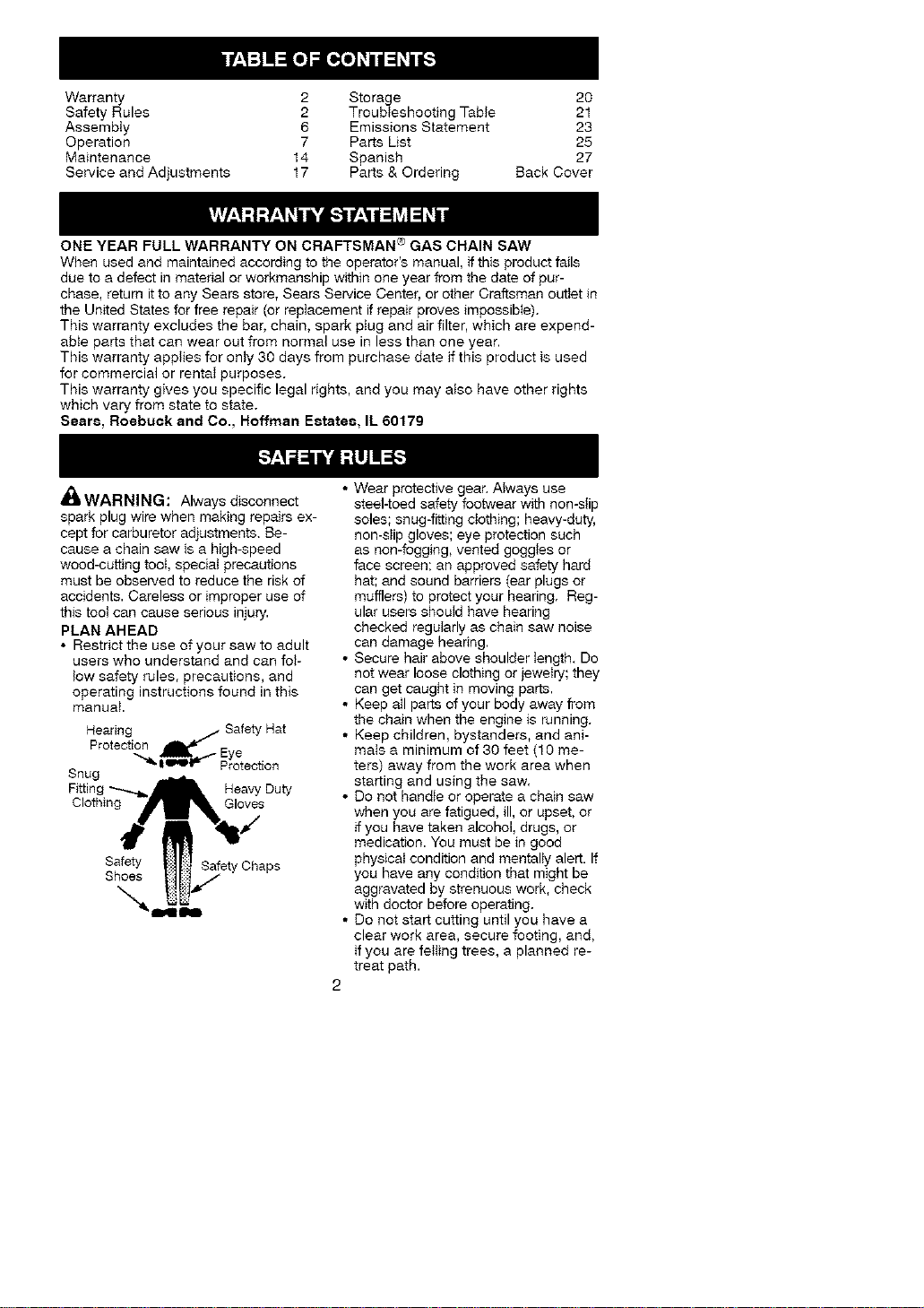
Hearing Safety Hat
Protection
-____S_ Eye
_ I_'°r_ Protection
Snug
Fitting "_..._ Heavy Duty
Clothing__ j¢,,_Gloves
Safety t-)_l_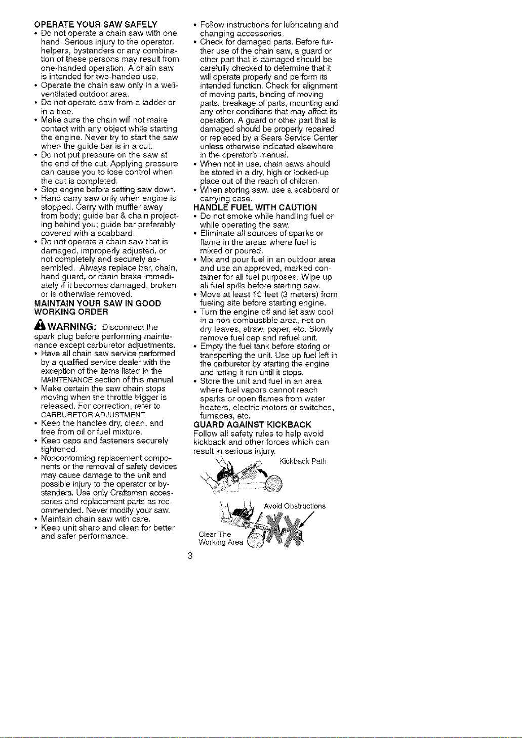
OPERATEYOURSAWSAFELY
• Donotoperateachainsawwithone
hand.Seriousinjurytotheoperator,
hetpers,bystandersoranycombina-
tionofthesepersonsmayresultfrom
one-handedoperation.Achainsaw
isintendedfortwo-handeduse.
• Operatethechainsawonlyinawelt-
ventilatedoutdoorarea.
• Donotoperatesawfromaladderor
inatree.
• Makesurethechainwillnotmake
contactwithanyobjectwhilestarting
theengine.Nevertrytostartthesaw
whentheguidebarisinacut.
• Donotputpressureonthesawat
theendofthecut.Applyingpressure
can cause you to _ose control when
the cut is completed.
• Stop engine before setting saw down.
• Hand carry saw onty when engine is
stopped. Carry with muffler away
from body; guide bar & chain project-
ing behind you; guide bar preferably
covered with a scabbard.
• Do not operate a chain saw that is
damaged, improperly adjusted, or
not completely and securely as-
sembled. Atways reptace bar, chain,
hand guard, or chain brake immedi-
ately if it becomes damaged, broken
or is otherwise removed.
MAINTAIN YOUR SAW IN GOOD
WORKING ORDER
_WARNING: Disconnect the
spark plug before performing mainte-
nance except carburetor adjustments.
• Have nil chain saw service performed
by a qualified service dealer with the
exception of the items listed in the
MAINTENANCE section of this manual.
• Make certain the saw chain stops
moving when the throttle trigger is
released. For correction, refer to
CARBURETOR ADJUSTMENT
• Keep the handles dry, clean, and
free from oil or fuet mixture.
• Keep caps and fasteners securely
tightened.
• Nonconforming replacement compo-
nents or the removal of safety devices
may cause damage to the unit and
possible injury to the operator or by-
standers. Use onty Craftsman acces-
sones and replacement parts as rec-
ommended. Never modify your saw.
• Maintain chain saw with care.
• Keep unit sharp and clean for better
and safer performance.
• FoItow instructions for lubricating and
changing accessories.
• Check for damaged parts. Before fur-
ther use of the chain saw, a guard or
other part that is damaged should be
carefully checked to determine that it
will operate properly and perform its
intended function. Check for alignment
of moving parts, binding of moving
parts, breakage of parts, mounting and
any other conditions that may affect its
operation. A guard or other part that is
damaged shouM be properly repaired
or replaced by a Sears Service Center
unless otherwise indicated elsewhere
in the operator's manual.
• When not in use, chain saws should
be stored in a dry, high or locked-up
place out of the reach of children.
• When storing saw, use a scabbard or
carrying case.
HANDLE FUEL WITH CAUTION
• Do not smoke while handling fuel or
while operating the saw.
• Eliminate att sources of sparks or
flame in the areas where fuel is
mixed or poured,
• Mix and pour fueI in an outdoor area
and use an approved, marked con-
tainer for all fuel purposes. Wipe up
ait fuel spills before starting saw.
• Move at least 10 feet (3 meters) from
fueling site before starting engine.
• Turn the engine off and tet saw cooI
in a non-combustible area, not on
dry leaves, straw, paper, etc. Slowiy
remove fuei cap and refuel unit.
• Empty the fuet tank before storing or
transporting the unit. Use up fueI left in
the carburetor by starting the engine
and letting it run until it stops.
• Store the unit and fuel in an area
where fuel vapors cannot reach
sparks or open flames from water
heaters, electric motors or switches,
furnaces, etc.
GUARD AGAINST KICKBACK
Follow alI safety ruIes to help avoid
kickback and other forces which can
result in serious injury.
_ Kickback Path
_ILWARNING: Avoid kickback
which can resuIt in serious injury.
Kickback is the backward, upward or
sudden forward motion of the guide
bar occurring when the saw chain near
the upper tip of the guide bar contacts
any object such as a log or branch, or
when the wood closes in and pinches
the saw chain in the cut. Contacting a
foreign object in the wood can also re-
suit in loss of chain saw control
• Rotational Kickback can occur
when the moving chain contacts an
object at the upper tip of the guide
bar. This contact can cause the
chain to dig into the object, which
stops the chain for an instant. The
result is a lightning fast, reverse
reaction which kicks the guide bar up
and back toward the operator.
• Pinch-Kickback can occur when the
the wood ctoses in and pinches the
moving saw chain in the cut along
the top of the guide bar and the saw
chain is suddenly stopped. This sud-
den stopping of the chain results in a
reversal of the chain force used to
cut wood and causes the saw to
move in the opposite direction of the
chain rotation. The saw is driven
straight back toward the operator.
• Pull-In can occur when the moving
chain contacts a foreign object in the
wood in the cut along the bottom of
the guide bar and the saw chain is
suddenly stopped. This sudden stop-
ping puils the saw forward and away
from the operator and could easily
cause the operator to lose control of
the saw,
REDUCE THE CHANCE OF
KICKBACK
• Recognize that kickback can hap-
pen. With a basic understanding of
kickback, you can reduce the ele-
ment of surprise which contributes to
accidents.
• Never tet the moving chain contact
any object at the tip of the guide bar.
• Keep the working area free from ob-
structions such as other trees,
branches, rocks, fences, stumps,
etc. Eliminate or avoid any
obstruction that your saw chain couId
hit white you are cutting.
• When cutting a branch, do not let the
guide bar contact branch or other ob-
jects around it.
• Keep saw chain sharp and properly
tensioned, A loose or dull chain can
increase the chance of kickback, Fol-
low manufacturer's chain sharpening
and maintenance instructions. Check
tension at regular intervals, but never
with the engine running. Make sure
the bar nuts are securely tightened.
• Begin and continue cutting at futl
speed. If the chain is moving at a
slower speed, there is greater
chance of kickback occurring.
• Use extreme caution when re-enter-
ing a previous cut,
• Do not attempt cuts starting with the
tip of the bar (plunge cuts),
• Watch for shifting logs or other forces
that could close a cut and pinch or
fail into chain,
• Use the Reduced-Kickback Guide
Bar and Low-Kickback Chain speci-
fied for your saw,
Avoid Pinch-Kickback:
• Be extremely aware of situations or
obstructions that can cause material
to pinch the top of or otherwise stop
the chain.
• Do not cut more than one log at a
time.
• Do not twist the saw as the bar is
withdrawn from an undercut when
bucking.
Avoid Putl-ln:
• Always begin cutting with the engine
at full speed and the saw housing
against wood.
• Use wedges made of ptastic or wood.
Never use metal to ho_d the cut open.
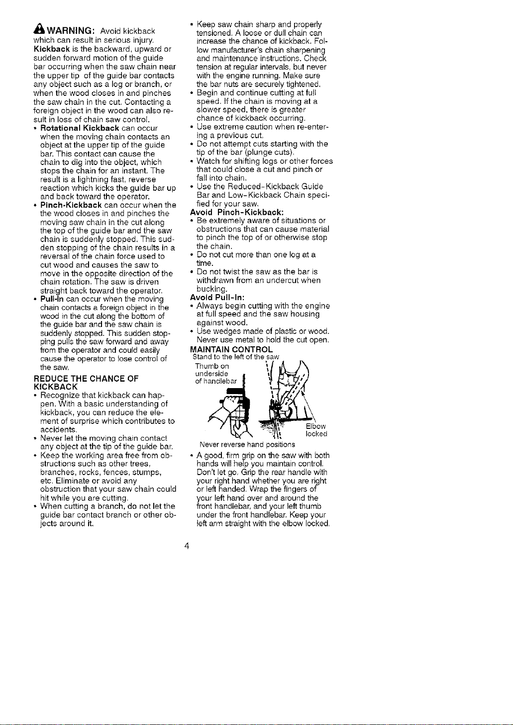
MAINTAIN CONTROL
Stand to the left of the saw
Thumb on
h O,s,de",{
Never reverse hand positions
• A good, firm grip on the saw with both
hands will heIp you maintain control.
Don't let go. Grip the rear handle with
your right hand whether you are right
or left handed. Wrap the fingers of
your left hand over and around the
front handlebar, and your teft thumb
under the front handlebar. Keep your
ieff arm straight with the elbow locked,
• Positionyourlefthandonthefront
handlebarsoitisinastraighttine
withyourrighthandontherear
handlewhenmakingbuckingcuts.
Neverreverserightandlefthand
positionsforanytypeofcutting.
• Standwithyourweightevenlybal-
ancedonbothfeet.
• Donotoverreach.Youcouidbe
drawnorthrownoffbalanceandlose
controlofthesaw.
• Donotcutaboveshoulderheight,tt
isdifficuIttomaintaincontrolofsaw
aboveshoulderheight.
KICKBACKSAFETYFEATURES
WARNING:Thefollowingfea-
turesareincludedonyoursawtohelp
reducethehazardofkickback;however,
suchfeatureswitlnottotallyeliminate
thisdanger.Donotretyonlyonsafety
devices.Foltowatlsafetyrulestohetp
avoidkickbackandotherforceswhich
canresultinseriousinjury.
• FrontHandGuard,designedtoreduce
thechanceofyourlefthandcontact-
ingthechainifyourhandslipsoffthe
fronthandlebar.
• Positionoffrontandrearhandlebars,
designedwithdistancebetweenhan-
dlesand"in-line" with each other. The
spread and "in-line" position of the
hands provided by this design work
together to give balance and resis-
tance in controlling the pivot of the
saw back toward the operator ff kick-
back occurs.
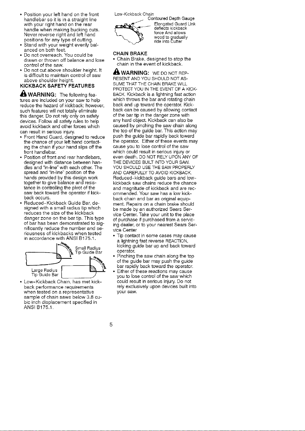
• Reduced-Kickback Guide Bar, de-
signed with a smatl radius tip which
reduces the size of the kickback
danger zone on the bar tip. This type
of bar has been demonstrated to sig-
nificantly reduce the number and se-
riousness of kickbacks when tested
in accordance with ANSI B175.1.
_& Smail Radius
Tip Guide Bar
Large Radius _ "_
Tip Guide Bar
• Low-Kickback Chain, has met kick-
back performance requirements
when tested on a representative
sample of chain saws below 3.8 cu-
bic inch displacement specified in
ANSi B175.1.
Low-Kickback Chain
Contoured Depth Gauge
_._ longated Guard Link
deflects kickback
force And allows
wood to gradually
ride into Cutter
CHAIN BRAKE
• Chain Brake, designed to stop the
chain in the event of kickback.
_,WARNING: WEDONOTREP-
RESENTAND YOU SHOULD NOT AS-
SUME THAT THE CHAIN BRAKE WILL
PROTECT YOU IN THE EVENT OF A KICK-
BACK Kickback is a lightning fast action
which throws the bar and rotating chain
back and up toward the operator. Kick-
back can be caused by aIIowing contact
of the bar tip in the danger zone with
any hard object. Kickback can also be
caused by pinching the saw chain along
the top of the guide bar. This action may
push the guide bar rapidly back toward
the operator. Either of these events may
cause you to Iose control of the saw
which could result in serious injury or
even death. DO NOT RELY UPON ANY OF
THE DEVICES BUILT {NTOYOUR SAW.
YOU SHOULD USE THE SAW PROPERLY
AND CAREFULLY TOAVOID KICKBACK.
Reduced-kickback guide bars and Iow-
kickback saw chains reduce the chance
and magnitude of kickback and are rec-
ommended. Your saw has a tow kick-
back chain and bar as original equip-
ment. Repairs on a chain broke should
be made by an authorized Sears Ser-
vice Center. Take your unit to the place
of purchase ff purchased from a servic-
ing dealer, or to your nearest Sears Ser-
vice Center
• Tip contact in some cases may cause
a lightning fast reverse REACTION,
kicking guide bar up and back toward
operator.
• Pinching the saw chain along the top
of the guide bar may push the guide
bar rapidly back toward the operator.
• Either of these reactions may cause
you to lose control of the saw which
could result in serious injury. Do not
rely exclusively upon devices built into
your SaW.
This unit is not equipped with an anti-
vibration system and is intended for
occasional use only.
SAFETY NOTICE: Exposure to vibra-
tions through prolonged use of gasoline
powered hand tools could cause blood
vessel or nerve damage in the fingers,
hands, and joints of people prone to
circulation disorders or abnormal swell-
ings. Prolonged use in cold weather has
been linked to blood vessel damage in
otherwise healthy people. If symptoms
occur such as numbness, pain, loss of
strength, change in skin color or texture,
or toss of feeling in the fingers, hands, or
joints, discontinue tile use of this toot
and seek medical attention. An anti-vi-
bration system does not guarantee the
avoidance of these problems. Users
who operate power tools on a continual
and regular basis must monitor closely
their physical condition and the condition
of this tool.
CHAIN BRAKE: If this saw is to be
used for commercial logging, a chain
brake is required and shall not be re-
moved or otherwise disabled to com-
pty with Federal OSHA Regutations for
Commercial Logging.
SPARK ARRESTING SCREEN: Your
saw is equipped with a temperature
limiting muffler and spark arresting
screen which meets the requirements
of California Codes 4442 and 4443.
All U.S, forest land and the states of
Catifornia, Idaho, Maine, Minnesota,
New Jersey, Oregon, and Washington
require by law that many internal com-
bustion engines to be equipped with a
spark arresting screen. If you operate
a chain saw in a state or locale where
such regulations exist, you are legally
responsible for maintaining the operat-
ing condition of these parts. Failure to
do so is a violation of the law. Refer to
the Customer Responsibilities chart in
the MAINTENANCE section.
STANDARDS: This chain saw is tisted
by Underwriters Laboratories, Inc. in ac-
cordance with American National Stan-
dards for Gasoline-Powered Chain
Saws Safety Requirements (ANSI
B175,1-2000).
dI_WARNING: Before using chain
saw_ ensure a_t fasteners are secure,
CARTON CONTENTS
Check carton contents against the fol-
lowing list.
Model 358.350880
• Chain saw (fully assembled)
• 2-cycle engine oil
• Carrying case
• Bar and chain tube
Examine parts for damage. Do not use
damaged parts.
If you need assistance or find that parts
are missing or damaged, please caIt
1-800-235-5878.
NOTE: It is normal to hear the fueI filter
rattle in an empty fuel tank.
Your unit has been factory tested and
the carburetor precisely adjusted. As a
result you may smelt gasoline or find a
drop of oil/f_et residue on the muffler
when you unpack the unit.
ASSEMBLY
Your saw is fully assembled; no
assembly is necessary.
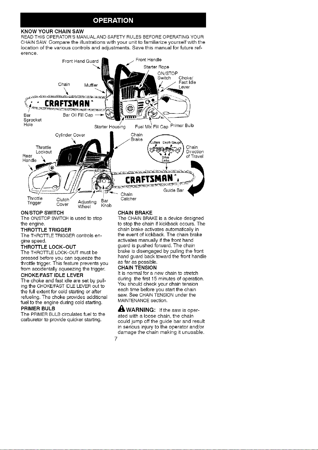
KNOW YOUR CHAIN SAW
READ THIS OPERATOR'S MANUAL AND SAFETY RULES BEFORE OPERATING YOUR
CHAIN SAW. Compare the ittustrations with your unit to familiarize yourself with the
location of the various controts and adjustments. Save this manual for future ref-
erence,
Front Hand Guard
Starter Rope
ON/STOP
Switch Choke/
Fast Idle
Chain Muffler Lever
CRAFTSMAN°
Bar Bar Oil FilI Cap
Sprocket
Hole Starter Housing Fill Cap PdmerBulb
CylinderCover Chain
Chain
Throttle ) Direction
Lockout
Rear of Travet
Handle _
Throttle Clutch Adjusting Bar
Trigger Cover Wheel Knob
ON/STOP SWITCH
The ON/STOP SWtTCH is used to stop
the engine.
THRO'FrLE TRIGGER
The THROT[LE TRIGGER controls en-
gine speed.
THROTrLE LOCK-OUT
The THRO_LE LOCK-OUT must be
pressed before you can squeeze the
throttle trigger. This feature prevents you
from accidentally squeezing the trigger.
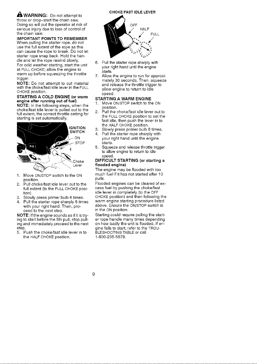
CHOKE/FAST IDLE LEVER
The choke and fast idle are set by pull-
ing the CHOKE/FAST IDLE LEVER out to
the full extent for cold starting or after
refueling, The choke provides additional
fuel to the engine during cotd starting.
PRIMER BULB
The PRIMER BULB circuIates fuet to the
carburetor to provide quicker starting.
Guide Bar
Chain
Catcher
CHAIN BRAKE
The CHAIN BRAKE is a device designed
to stop the chain if kickback occurs. The
chain brake activates automaticatty in
the event of kickback. The chain brake
activates manualty if the front hand
guard is pushed forward. The chain
brake is disengaged by puiling the front
hand guard back toward the front handle
as far as possible.
CHAIN TENSION
tt is norma_ for a new chain to stretch
during the first 15 minutes of operation.
You should check your chain tension
each time before you start the chain
saw. See CHAINTENSION under the
MAINTENANCE section.
A0&WARNING: Ifthe saw is oper-
ated with a toose chain, the chain
coutd jump off the guide bar and result
in serious injury to the operator and/or
damage the chain making it unusable.
7
BEFORESTARTINGENGINE
_ll, WARNING: Muffter is very hot
during and after use. Do not touch the
muffIer or allow combustible material
such as dry grass or fuel to do so.
_LWARNING: Be sure to read the
fuel handling information in the safety
rules section of this manual before you
begin, tf you do not understand the
fuel handling information do not at-
tempt to fuel your unit. Seek help from
someone that does understand the in-
formation or can the customer assis-
tance help line at 1-800-235-5878.
GUIDE BAR AND CHAIN OIL
The bar and chain require lubrication.
The chain oiler provides continuous
Iubrication to the chain and guide bar.
Be sure to fiIt the bar oil tank when you
fill the fueI tank (Capacity = 6.8 ft. oz.).
Lack of oil win quickly ruin the bar and
chain. Too little oil will cause overheat-
ing shown by smoke coming from the
chain and/or discoloration of the bar.
For maximum guide bar and chain life,
we recommend you use Craftsman
chain saw bar oil. If Craftsman bar oit
is not available, you may use a good
grade SAE 30 oiI until you are aMe to
obtain Craftsman brand. The oil output
is automatically metered during opera-
tion. Your saw will use approximately
one tank of bar oil for every tank of fuel
mix. Atways fill the bar oil tank when
you fill the fuet tank.
FUELING ENGINE
_WARNING: Remove fuel cap
slowly when refueling.
This engine is certified to operate on
unteaded gasoline. Before operation,
gasotine must be mixed with a good
quatity synthetic 2-cycIe air-cooIed en-
gine oil. We recommend Craftsman
brand synthetic oil. Mix gasoline and
oit at a ratio of 40:1. A 40:1 ratio is ob-
tained by mixing 3.2 ounces of oil with
1 gailon of unleaded gasoline. Included
with this saw is a 3.2 ounce container of
oil Pour the entire contents of this con-
tainer into 1 gallon of gasoline to
achieve the proper fuel mixture.
DO NOT USE automotive or boat oil
These oils wiit cause engine damage.
When mixing fuel fottow the instruc-
tions printed on the oil container. Once
oil is added to the gasoline, shake
container momentarily to assure that
the fuet is thoroughly mixed. Always
read and follow the safety rules relat-
ing to fueI before fueling your unit.
IMPORTANT
Experience indicates that alcohol-
blended fueis (called gasohol or using
ethanot or methanol) can attract mois-
ture which leads to separation and
formation of acids during storage. Acidic
gas can damage the fuel system of an
engine while in storage. To avoid engine
problems, the fuel system should be
emptied before storage for 30 days or
longer. Drain the gas tank, start the en-
gine and let it run until the fuel lines and
carburetor are empty. Use fresh fuel
next season. Never use engine or car-
buretor cteaner products in the fuel tank
or permanent damage may occur,
See the STORAGE section for additionai
information
CHAIN BRAKE
Ensure chain brake is disengaged by
pulling the front hand guard back toward
the front handle as far as possible. The
chain brake must be disengaged before
cutting with the saw.
_ WARNING: The chain must not
move when the engine runs at idle
speed. If the chain moves at idle
speed refer to CARBURETOR ADJUST-
MENT within this manual. Avoid contact
with the muffler. A hot muffler can
cause serious burns.
STOPPING YOUR ENGINE
• Release the throttle trigger.
• Move ON/STOP switch to the STOP
position.
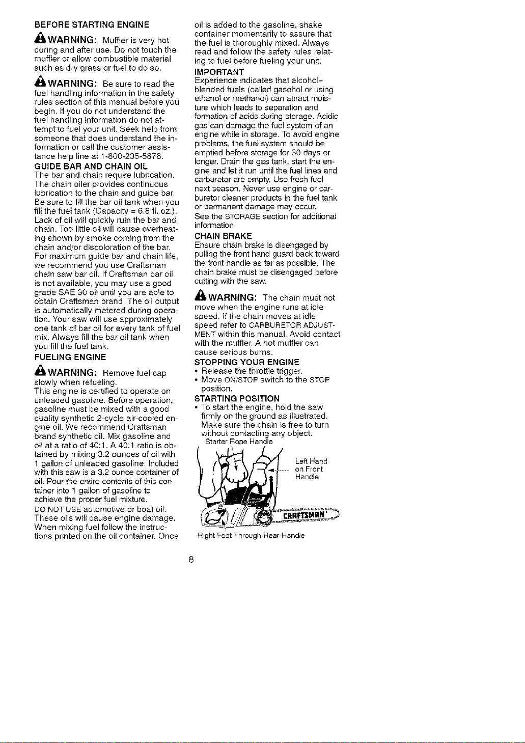
STARTING POSITION
• To start the engine, hold the saw
firmly on the ground as iitustrated.
Make sure the chain is free to turn
without contacting any object.
Starter Rope Handle
on Front
_ Handle
Right Foot Through Rear Handle
_ILWARNING: Do not attempt to
throw or drop-start the chain saw,
Doing so witt put the operator at risk of
serious injury due to loss of controI of
the chain saw.
IMPORTANT POINTS TO REMEMBER
When puIIing the starter rope, do not
use the full extent of the rope as this
can cause the rope to break. Do not let
starter rope snap back. HoM the han-
dle and let the rope rewind stowty.
For cold weather starting, start the unit
at FULL CHOKE; allow the engine to
warm up before squeezing the throttle
trigger.
NOTE: Do not attempt to cut material
with the choke/fast idle lever in the FULL
CHOKE position.
STARTING A COLD ENGINE (or warm
engine after running out of fuel)
NOTE: tn the following steps, when the
choke/fast idle lever is pulled out to the
fult extent, the correct throttte setting for
starting is set automatically,
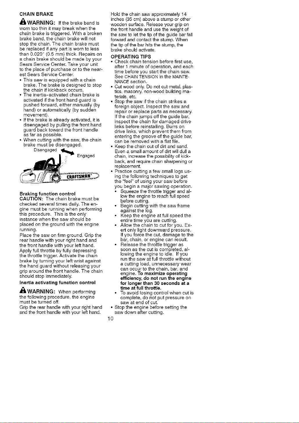
IGNITION
SWITCH
ON
Lever
1. Move ON/STOP switch to the ON
position.
2. Pult choke/fast idle lever out to the
full extent (to the FULL CHOKE posi-
tion).
3. Slowly press primer bulb 6 times.
4. Putt the starter rope sharply 5 times
with your right hand. Then, pro-
ceed to the next step.
NOTE: Ifthe engine sounds as if it is try-
ing to start before the 5th pull, stop pull-
ing and immediately proceed to the next
step.
5. Push the choke/fast idle lever in to
the HALF CHOKE position.
CHOKE/FAST IDLE LEVER
oil iFHALF
ITm . / FULL
6. Putt the starter rope sharply with
your right hand until the engine
starts.
7, Allow the engine to run for approxi-
mately 30 seconds. Then, squeeze
and release the throttle trigger to
allow engine to return to idle
speed.
STARTING A WARM ENGINE
1. Move ON/STOP switch to the ON
position.
2. Putt the choke/fast idle lever out to
the FULL CHOKE position to set the
fast idle, then push the lever in to
the HALF CHOKE position.
3. Stowly press primer bulb 6 times.
4. Putt the starter rope sharply with
your right hand untit the engine
starts.
5. Squeeze and release throttle trigger
to allow engine to return to idle
speed.
DIFFICULT STARTING (or 8tatting a
flooded engine)
The engine may be flooded with too
much fuet if it has not started after 10
pulls.
Flooded engines can be cleared of ex-
cess fuel by pushing the choke/fast
idle lever in completeIy (to the OFF
CHOKE position) and then following the
warm engine starting procedure listed
above. Ensure the ON/STOP switch is
in the ON position,
Starting could require pulling the start-
er rope handle many times depending
on how badly the unit is flooded, If en-
gine fails to start, refer to the TROU-
BLESHOOTING TABLE or call
1-800-235-5878.
CHAINBRAKE
_b'WARNING: If the brake band is
worn too thin it may break when the
chain brake is triggered. With a broken
brake band, the chain brake will not
stop the chain. The chain brake must
be replaced if any part is worn to tess
than 0.020" (0.5 ram) thick. Repairs on
a chain brake should be made by your
Sears Service Center. Take your unit
to the piace of purchase or to the near-
est Sears Service Center.
• This saw is equipped with a chain
brake. The brake is designed to stop
the chain if kickback occurs.
• The inertia-activated chain brake is
activated if the front hand guard is
pushed forward, either manually (by
hand) or automatically (by sudden
movement).
• Ifthe brake is already activated, it is
disengaged by putting the front hand
guard back toward the front handle
as far as possible.
• When cutting with the saw, the chain
brake must be disengaged.
Braking function control
CAUTION: The chain brake must be
checked severat times daily. The en-
gine must be running when performing
this procedure. This is the onty
instance when the saw should be
placed on the ground with the engine
running.
Place the saw on firm ground. Grip the
rear handle with your right hand and
the front handie with your left hand.
Apply futt throttte by fully depressing
the throttle trigger. Activate the chain
brake by turning your Ieft wrist against
the hand guard without releasing your
grip around the front handle. The chain
should stop immediately.
Inertia activating function control
_[LWARNING: When performing
the following procedure, the engine
must be turned off,
Grip the rear handie with your right hand
and the front handle with your teft hand.
Hotd the chain saw approximately 14
inches (35 cm) above a stump or other
wooden surface. Reiease your grip on
the front handle and use the weight of
the saw to let the tip of the guide bar fall
forward and contact the stump, When
the tip of the bar hits the stump, the
brake should activate.
OPERATING TIPS
• Check chain tension before first use,
after 1 minute of operation, and each
time before you start the chain saw.
See CHAIN TENSION in the MAINTE-
NANCE section.
• Cut wood only. Do not cut metal, plas-
tics, masonry, non-wood building ma-
terials, etc.
• Stop the saw if the chain strikes a
foreign object. Inspect the saw and
repair or replace parts as necessary,
If the chain jumps off the guide bar,
inspect the chain for damaged drive
tinks before reinstalling. Burrs on
drive links, which prevent them from
entering the groove of the guide bar,
can be removed with a flat fiIe.
• Keep the chain out of dirt and sand.
Even a small amount of dirt will dull a
chain, increase the possibility of kick-
back, and require chain sharpening or
replacement.
• Practice cutting a few small logs us-
ing the following techniques to get
the "feeF of using your saw before
you begin a major sawing operation.
• Squeeze the throttte trigger and al-
Iow the engine to reach fuli speed
before cutting.
• Begin cutting with the saw frame
against the log.
• Keep the engine at fuji speed the
entire time you are cutting.
•AlIow the chain to cut for you. Ex-
ert only light downward pressure.
If you force the cut, damage to the
bar, chain, or engine can result.
• Release the throttie trigger as
soon as the cut is completed, at-
towing the engine to idle. If you
run the saw at full throttle without
a cutting load, unnecessary wear
can occur to the chain, bar, and
engine. To maximize operating
efficiency, do not run the engine
for longer than 30 _econd8 at a
time at full throttle.
• To avoid losing control when cut is
complete, do not put pressure on
saw at end of cut.
• Stop the engine before setting the
saw down after cutting.
10
TREE FELLING TECHNIQUES
_II, WARNING: Check for broken or
dead branches which can fall while cut-
ting causing serious injury. Do not cut
near buildings or electrical wires if you
do not know the direction of tree falt, nor
cut at night since you will not be aIe to
see well, nor during bad weather such
as rain, snow, or strong winds, etc.
Ifthe tree makes contact with any utility
Iine, the utility company should be noti-
fied immediately.
•Carefuily plan your sawing operation
in advance.
• Ctear the work area. You need a ciear
area nil around the tree so you can
have secure footing.
• The chain saw operator shoutd keep
on the uphill side of the terrain as the
tree is likely to roll or slide downhill
after it is felled.
• Study the natural conditions that can
cause the tree to fall in a particular di-
rection.
Natural conditions that can cause a tree
to fail in a particular direction include:
• The wind direction and speed.
• The lean of the tree. The tean of a
tree might not be apparent due to un-
even or sloping terrain, Use a piumb
or level to determine the direction of
tree lean.
• Weight and branches on one side.
• Surrounding trees and obstactes.
Look for decay and rot. If the trunk is
rotted, it can snap and fall toward the
operator. Make sure there is enough
room for the tree to fall. Maintain a dis-
tance of 2 1/2tree lengths from the near-
est person or other objects. Engine
noise can drown out a warning call.
Remove dirt, stones, loose bark, naiis,
staples, and wire from the tree where
cuts are to be made.
Plan a ctear retreat path to the rear
and diagonal to the line of fail
_t__ Plan a clear retreat path
;t'- - -O" "_ _Direction of Fa]_
FELLING LARGE TREES
(6 inches (15 cm) in diameter or larger)
The notch method is used to fell large
trees. A notch is cut on the side of the
tree in the desired direction of fall. After
a felling cut is made on the opposite
side of tree, the tree wiII tend to fail into
the notch.
NOTE: If the tree has large buttress
roots, remove them before making the
notch, tf using saw to remove buttress
roots, keep saw chain from contacting
ground to prevent dutiing of the chain.
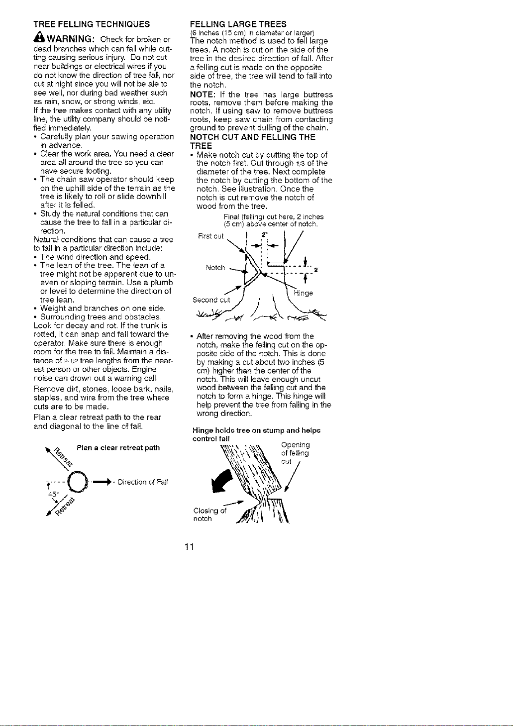
NOTCH CUT AND FELLING THE
TREE
• Make notch cut by cutting the top of
the notch first. Cut through _,/3of the
diameter of the tree. Next compiete
the notch by cutting the bottom of the
notch. See iflustration. Once the
notch is cut remove the notch of
wood from the tree.
FinaI (felling) cut here, 2 inches
(5 cm) above center of notch.
Firstc°t
i' _...L
Notch --.... __._2
7 Hinge
• After removing the wood from the
notch, make the felling cut on the op-
posite side of the notch. This is done
by making a cut about two inches (5
cm) higher than the center of the
notch. This wilt leave enough uncut
wood between tile felting cut and the
notch to form a hinge. This hinge wilt
help prevent the tree from falting in the
wrong direction.
Hinge holds tree on stump and helps
control tall
Opening
of feIling
Closing of
notch
11
NOTE: Before felling cut is complete,
use wedges to open the cut if necessary
to contro_ the direction of fail. To avoid
kickback and chain damage, use wood
or ptastic wedges, but never steel or iron
wedges.
• Be alert to signs that the tree is
ready to falt: cracking sounds, widen-
ing of the feI_ing cut, or movement in
the upper branches.
• As tree starts to fall, stop saw, put it
down, and get away quickly on your
ptanned retreat path.
• DO NOT cut down a partially fatIen tree
with your saw. Be extremely cautious
with partialIy falten trees that may be
poorty supported. When a tree doesn't
falt completely, set the saw aside and
pult down the tree with a cable winch,
b_ock and tackle, or tractor.
CUTTING A FALLEN TREE
(BUCKING)
Bucking is the term used for cutting a
fallen tree to the desired _ogsize.
_IJWARNING: Do not stand on the
tog being cut. Any portion can rott
causing toss of footing and control, Do
not stand downhill of the log being cut.
IMPORTANT POINTS
• Cut only one log at a time.
• Cut shattered wood very carefully;
sharp pieces of wood could be flung
toward operator.
• Use a sawhorse to cut smatt logs.
Never aItow another person to hold
the Iog white cutting and never hold
the Iog with your _egor foot.
• Do not cut in an area where togs,
_imbs, and roots are tang_ed such as
in a blown down area. Drag the togs
into a clear area before cutting by
pu_ting out exposed and cleared togs
first.
TYPES OF CUTTING USED FOR
BUCKING
_ll WARNING: If saw becomes
pinched or hung in a log, don't try to
force it out. You can _ose control of the
saw resuIting in injury and/or damage
to the saw. Stop the saw, drive a
wedge of plastic or wood into the cut
until the saw can be removed easily.
Restart the saw and carefully reenter
the cut. To avoid kickback and chain
damage, do not use a metal wedge.
Do not attempt to restart your saw
when it is pinched or hung in a log.
Use a wedge to remove pinched saw
Turn saw OFF and use e plastic or
wooden wedge to force cut open.
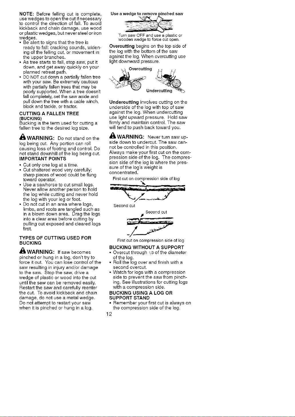
Overcutting begins on the top side of
the log with the bottom of the saw
against the _og.When overcutting use
light downward pressure.
, ._ 2vercutting fr_ _/
..... Undercutting_;
Undercutting invotves cutting on the
underside of the log with top of saw
against the tog. When undercutting
use light upward pressure. Ho_d saw
flrmty and maintain control. The saw
wilt tend to push back toward you.
_WARNING: Never turn saw up-
side down to undercut. The saw can-
not be controlled in this position.
Always make your first cut on the com-
pression side ofthe log. The compres-
sion side of the tog is where the pres-
sure of the log's weight is
concentrated.
Fgst cut on compression side of log
Second cut
Second cut
First cut on compression side of log
BUCKING WITHOUT A SUPPORT
• Overcut through 1/3of the diameter
of the log.
• Roll the Iog over and finish with a
second overcut.
• Watch for _ogs with a compression
side to prevent the saw from pinch-
ing. See ittustrations for cutting togs
with a compression side.
BUCKING USING A LOG OR
SUPPORT STAND
• Remember your first cut is a_ways on
the compression side of the log.
12
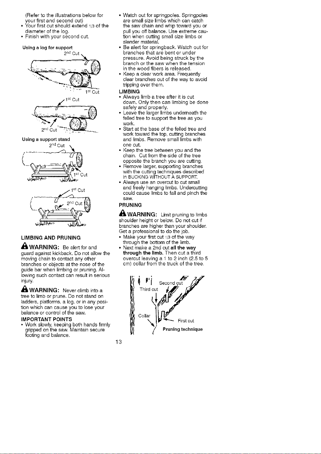
(Refertotheillustrationsbelowfor
yourfirstandsecondcut)
• Yourfirstcutshouldextend1/3ofthe
diameterofthelog.
• Finishwithyoursecondcut.
Usinga log for support
2r_dCut
" -:'_ ]StCu t
Using a support stand
2ndCut _
1stCut
L
LIMBING AND PRUNING
'_ WARNING: Be alert for and
guard against kickback. Do not allow the
moving chain to contact any other
branches or objects at the nose of the
guide bar when limbing or pruning. Al-
lowing such contact can result in serious
injuly.
_ll WARNING: Never climb into a
tree to limb or prune. Do not stand on
ladders, platforms, a log, or in any posi-
tion which can cause you to lose your
balance or control of the saw.
IMPORTANT POINTS
• Work slowly, keeping both hands firmty
gripped on the saw. Maintain secure
footing and balance.
• Watch out for springpoles. SpringpoIes
are smalt size limbs which can catch
the saw chain and whip toward you or
pull you off balance. Use extreme cau-
tion when cutting small size limbs or
slender material.
• Be alert for springback. Watch out for
branches that are bent or under
pressure. Avoid being struck by the
branch or the saw when the tension
in the wood fibers is released.
• Keep a clear work area. Frequently
clear branches out of the way to avoid
tripping over them.
LIMBING
• Always Iimb a tree after it is cut
down. Onty then can limbing be done
safely and properly.
• Leave the larger limbs underneath the
felled tree to support the tree as you
work.
• Start at the base of the felled tree and
work toward the top, cutting branches
and limbs. Remove smaII limbs with
one cut.
• Keep the tree between you and the
chain. Cut from the side of the tree
opposite the branch you are cutting.
• Remove larger, supporting branches
with the cutting techniques described
in BUCKING WITHOUT A SUPPORT.
• Always use an overcut to cut small
and freely hanging limbs. Undercutting
could cause limbs to fall and pinch the
SaW,
PRUNING
'_kWARNING: Limit pruning to limbs
shoulder height or below. Do not cut if
branches are higher than your shoulder.
Get a professional to do the job.
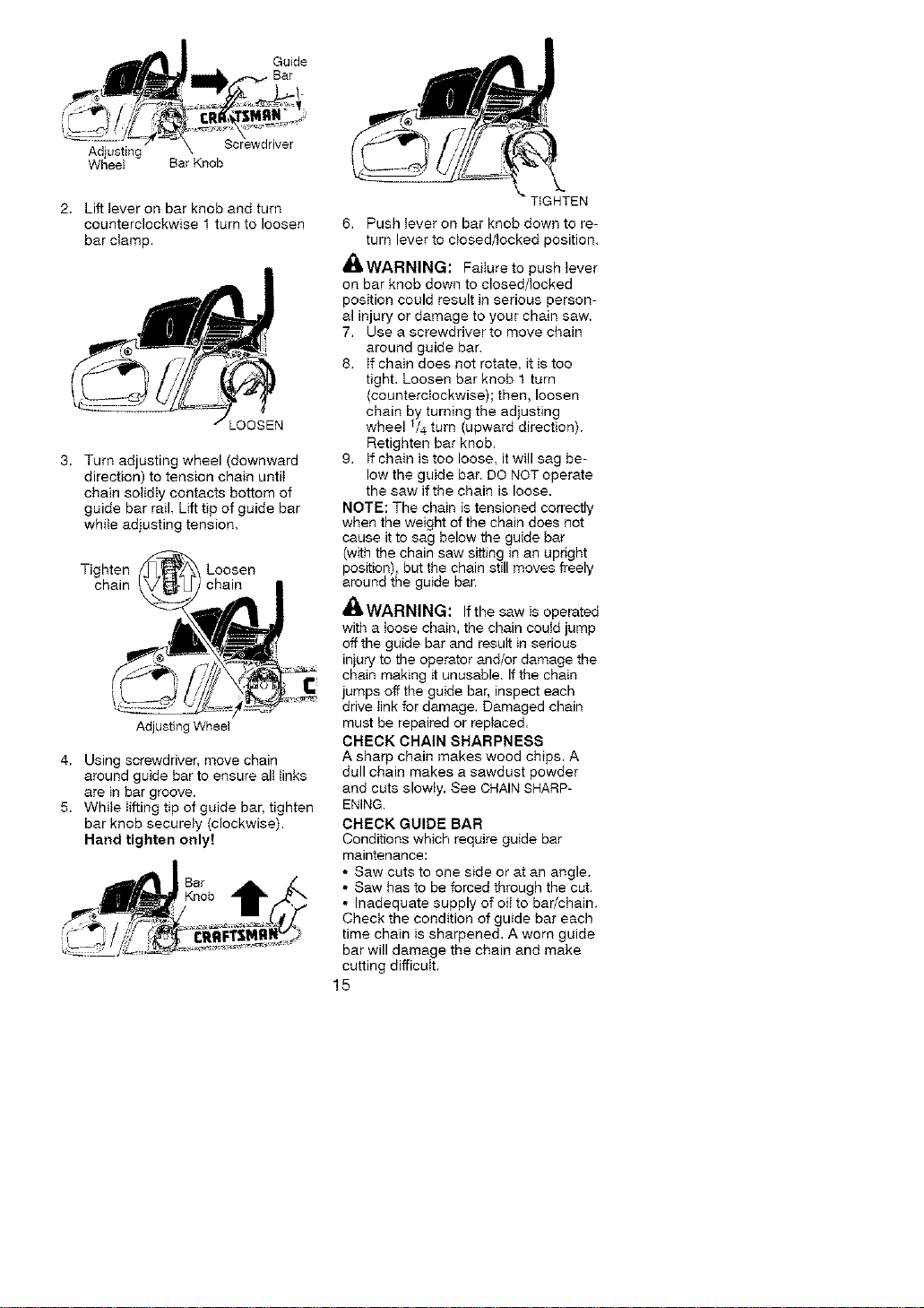
• Make your first cut 1/3of the way
through the bottom of the limb.
• Next make a 2nd cut all the way
through the limb. Then cut a third
overcut leaving a 1 to 2 inch (2.5 to 5
cm) collar from the truck of the tree.
13
s°con0c t//
Third cN,%tt_/
Oo,lar _[,_ First cut
/ Pruning technique

CUSTOMERRESPONSIBILITIES
_WARNING: Disconnect the spark plug before performing maintenance
except for carburetor adjustments.
Filt in dates as you complete Before After Ever Every Service
regular service Use Use 5 hrs 25 hrs. Yeady Dates
Check for damaged/worn parts .,I
Check for loose fasteners/parts
Check chain tension i_"
Check chain sharpness _'
Check guide bar _'
Check fuel mixture leveI _'
Check guide bar and chain oit _'_
Inspect and ctean unit &decaIs _"
Check chain brake /I
CIean guide bar groove
Clean air filter /-"
C_ean/inspect muffler and spark
arresting screen _'_
Replace spark plug and fueI filter _-
GENERAL RECOMMENDATIONS
The warranty on this unit does not cov-
er items that have been subjected to
operator abuse or negligence. To re-
ceive futt vatue from the warranty, the
operator must maintain unit as
instructed in this manual, Various ad-
justments wilt need to be made period-
icaHy to propedy maintain your unit.
• Once a year, replace the spark plug,
air filter, and check guide bar and
chain for wear. A new spark plug and
air fitter assures proper air-fue_ mixture
and helps your engine run better and
last _onger.
CHECK FOR DAMAGED OR
WORN PARTS
Contact your Sears Service Center for
reptacement of damaged or worn parts.
NOTE: It is norma_ for a smalt amount of
oiI to appear under the saw after engine
stops. Do not confuse this with a leaking
oit tank.
• ON/STOP Sw_tch - Ensure ON/STOP
switch functions properly by moving
the switch to the STOP position. Make
sure engine stops; then restart engine
and continue.
• Fuet Tank - Do not use saw if fuel
tank shows signs of damage or leaks.
• Oil Tank - Do not use saw if oil tank
shows signs of damage or leaks.
CHECK FOR LOOSE
FASTENERS AND PARTS
• Bar Knob
• Chain
• Muffler
• Cylinder Shield
• Air Fitter
• Handle Screws
• Vibration Mounts
• Starter Housing
• Front Hand Guard
CHECK CHAIN TENSION
_WARNING: Wear protective
gloves when handling chain. The chain
is sharp and can cut you even when it is
not moving.
Chain tension is very important, Chains
stretch during use. This is especiatty true
during the first few times you use your
saw. A}ways check chain tension each
time before you start the chain saw.
1. Use a screwdriver to move chain
around guide bar to ensure kinks
do not exist. The chain should ro-
tate freeSy.
14
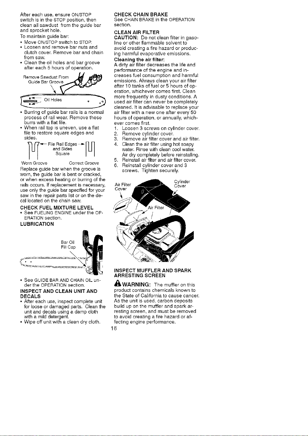
Guide
Bar
Adjusting
Wheel Bar Knob
2. Lift lever on bar knob and turn
counterclockwise 1 turn to loosen
bar clamp.
_OOSEN
3. Turn adjusting wheel (downward
direction) to tension chain untit
chain solidly contacts bottom of
guide bar rail. Lift tip of guide bar
whiIe adjusting tension.
Tighten Loosen
chain chain
Adjusting Wheel
4. Using screwdriver, move chain
around guide bar to ensure all links
are in bar groove.
5. While Iifting tip of guide bar, tighten
bar knob securely (clockwise).
Hand tighten onlyt
TIGHTEN
6. Push lever on bar knob down to re-
turn lever to closed/locked position.
_4_WARNING: Failure to push lever
on bar knob down to closed/locked
position could result in serious person-
al injury or damage to your chain saw.
7. Use a screwdriver to move chain
around guide bar.
8. tf chain does not rotate, it is too
tight. Loosen bar knob 1 turn
(counterclockwise); then, loosen
chain by turning the adjusting
wheel 1/4.turn (upward direction).
Retighten bar knob.
g. If chain is too loose, it will sag be-
low the guide bar. DO NOT operate
the saw if the chain is loose.
NOTE: The chain is tensioned correctly
when the weight of the chain does not
cause it to sag below the guide bar
(with the chain saw sitting in an upright
position), but the chain still moves freely
around the guide bar.
_I_WARNING: If the saw is operated
with a loose chain, the chain could jump
off the guide bar and result in serious
injury to the operator and/or damage the
chain making it unusable. Ifthe chain
jumps off the guide bar, inspect each
drive link for damage. Damaged chain
must be repaired or replaced.
CHECK CHAIN SHARPNESS
A sharp chain makes wood chips. A
dull chain makes a sawdust powder
and cuts slowly. See CHAIN SHARP-
ENING.
CHECK GUIDE BAR
Conditions which require guide bar
maintenance:
• Saw cuts to one side or at an angle.
• Saw has to be forced through the cut,
• Inadequate supply of oil to bar/chain.
Check the condition of guide bar each
time chain is sharpened. A worn guide
bar will damage the chain and make
cutting difficult.
15
After each use, ensure ON/STOP
switch is in the STOP position, then
clean all sawdust from the guide bar
and sprocket hole.
To maintain guide bar:
• Move ON/STOP switch to STOR
• Loosen and remove bar Ruts and
clutch cover. Remove bar and chain
from saw.
• Clean the oft holes and bar groove
after each 5 hours of operation.
• Burring of guide bar rails is a normal
process of rail wear. Remove these
burrs with a flat file.
• When rail top is uneven, use a flat
file to restore square edges and
sides.
rT_ File Rail Edges _ [L _
and Sides
Square
Worn Groove Correct Groove
Replace guide bar when the groove is
worn, the guide bar is bent or cracked,
or when excess heating or burring of the
rails occurs, tf replacement is necessary.
use only the guide bar specified for your
saw in the repair parts list or on the de-
cal located on the chain saw.
CHECK FUEL MIXTURE LEVEL
• See FUELING ENGINE under the OP-
ERATION section.
LUBRICATION
Bar Oil
Fill Cap
• See GUIDE BAR AND CHAIN OIL un-
der the OPERATION section.
INSPECT AND CLEAN UNIT AND
DECALS
• After each use, inspect compIete unit
for loose or damaged parts. Clean the
unit and decals using a damp cloth
with a mild detergent.
• Wipe off unit with a clean dry cloth.
CHECK CHAIN BRAKE
See CHAIN BRAKE in the OPERATION
section.
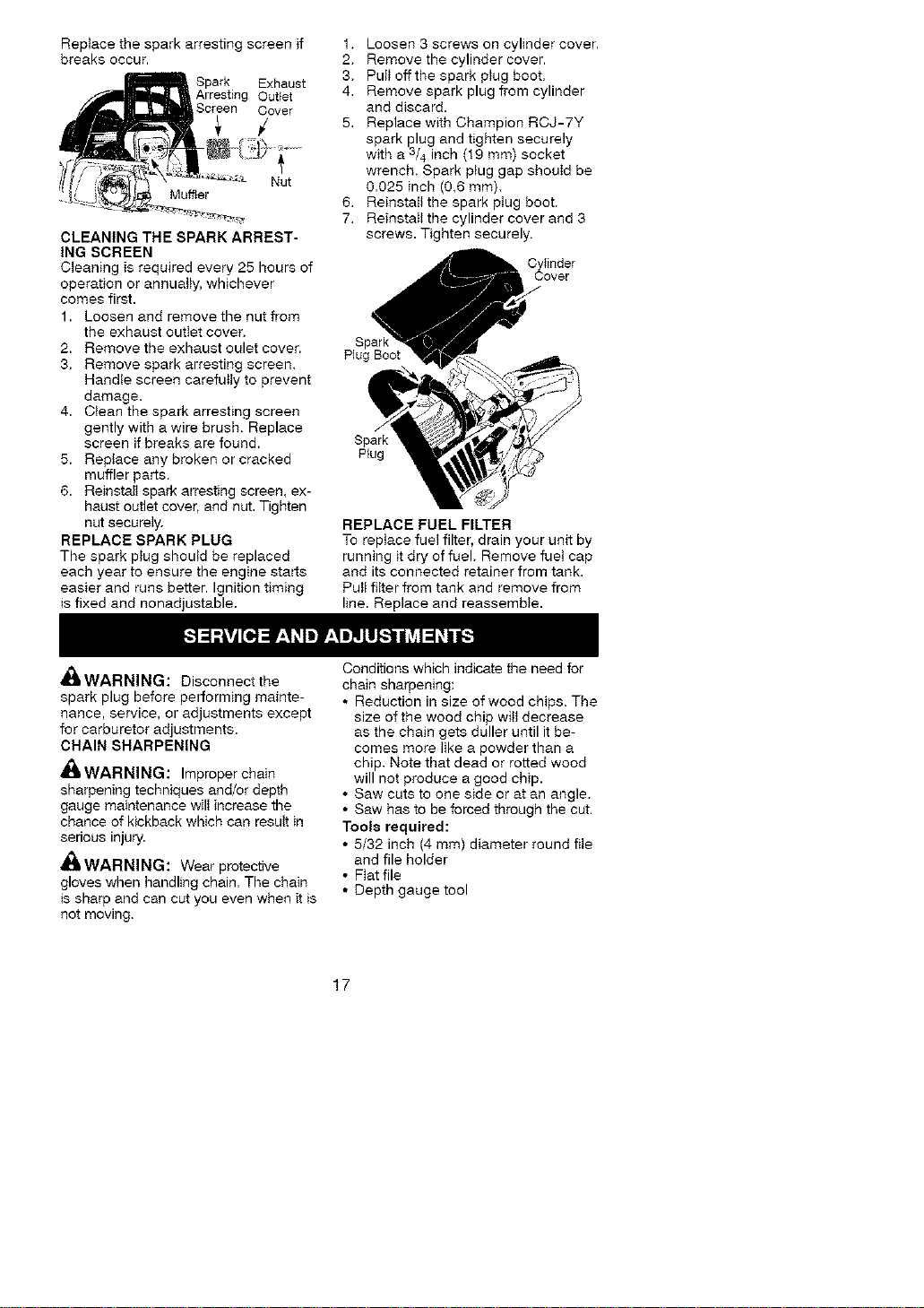
CLEAN AIR FILTER
CAUTION: Do not clean filter in gaso-
line or other flammable solvent to
avoid creating a fire hazard or produc-
ing harmful evaporative emissions.
Cleaning the air filter:
A dirty air filter decreases the life and
performance of the engine and in-
creases fuel consumption and harmful
emissions. Always clean your air filter
after 10 tanks of fuel or 5 hours of op-
eration, whichever comes first. Clean
more frequently in dusty conditions. A
used air filter can never be completely
cleaned, it is advisable to replace your
air filter with a new one after every 50
hours of operation, or annually, which-
ever comes first.
1. Loosen 3 screws on cylinder cover.
2. Remove cylinder cover.
3. Remove air filter cover and air filter.
4. Clean the air filter using hot soapy
water. Rinse with clean coot water.
Air dry completely before reinstalling.
5. Reinstall air filter and air filter cover.
6. ReinstatI cylinder cover and 3
screws. Tighten securely.
CyIinder
Air Filter Cover
Cover
INSPECT MUFFLER AND SPARK
ARRESTING SCREEN
_WARNING: The muffler on this
product contains chemicals known to
the State of California to cause cancer.
As the unit is used, carbon deposits
build up on the muffler and spark ar-
resting screen, and must be removed
to avoid creating a fire hazard or af-
fecting engine performance.
16
Replace the spark arresting screen ff
breaks occur.
Spark Exhaust
Arresting Out{et
Cover
/
CLEANING THE SPARK ARREST-
ING SCREEN
C_eaning is required every 25 hours of
operation or annuatiy, whichever
comes first.
1. Loosen and remove the nut from
the exhaust outlet cover.
2. Remove the exhaust oulet cover.
3. Remove spark arresting screen.
Handle screen carefuI_y to prevent
damage.
4. Clean the spark arresting screen
gently with a wire brush. Replace
screen if breaks are found.
5. RepIace any broken or cracked
muffler parts.
6. Reinsta_ spark arresting screen, ex-
haust outlet cover, and nut. Tighten
nut securely.
REPLACE SPARK PLUG
The spark p_ug shoutd be replaced
each year to ensure the engine starts
easier and runs better. Ignition timing
is fixed and nonadjustable.
1. Loosen 3 screws on cylinder cover.
2. Remove the cylinder cover.
3. Pull offthe spark piug boot.
4. Remove spark plug from cylinder
and discard.
5. Replace with Champion RCJ-7Y
spark plug and tighten securely
with a 3/4 inch (19 mm) socket
wrench. Spark p_ug gap shouId be
0.025 inch (0,6 mm).
6. Reinstall the spark ptug boot.
7. ReinstaIi the cylinder cover and 3
screws. Tighten securely.
Cylinder
Cover
Plug Eoot
Spark
Plug
REPLACE FUEL FILTER
To replace fue_ filter, drain your unit by
running it dry of fuel. Remove fuet cap
and its connected retainer from tank.
Pu_t _ter from tank and remove from
line. Replace and reassembIe.
_ItWARNING: Disconnect the
spark plug before performing mainte-
nance, service, or adjustments except
for carburetor adjustments.
CHAIN SHARPENING
,d_ WARNING: Improper chain
sharpening techniques and/or depth
gauge maintenance will increase the
chance of kickback which can result in
serious injury.
A_LWARNING: Wear protective
gloves when handling chain. The chain
is sharp and can cut you even when it is
not moving.
Conditions which indicate the need for
chain sharpening:
• Reduction in size of wood chips. The
size of the wood chip witt decrease
as the chain gets duller until it be-
comes more like a powder than a
chip, Note that dead or rotted wood
will not produce a good chip.
• Saw cuts to one side or at an angle.
• Saw has to be forced through the cut,
Tool8 required:
• 5/32 inch (4 mm) diameter round file
and file holder
• F_atfile
• Depth gauge tool
17
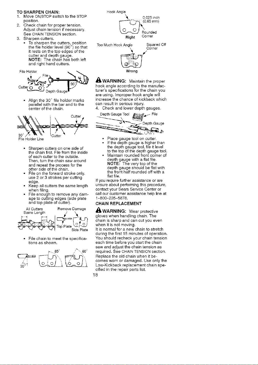
TO SHARPEN CHAIN:
1. Move ON/STOP switch to the STOP
position.
2. Check chain for proper tension.
Adjust chain tension if necessary.
See CHAIN TENSION section.
3. Sharpen cutters.
• To sharpen the cutters, position
the rite hoIder level (90 o) so that
it rests on the top edges of the
cutter and depth gauge.
NOTE: The chain has both left
and right hand cutters.
File Hider File, "*_ "'",_
Cutte__
Depth Gauger
• Align the 30 ° file holder marks
parallel with the bar and to the
center of the chain.
Hook Angle
k_ 0025 inch
Right Corner
Too Much Hook Angle Squared Off
/orner
Wrong
din, WARNING: Maintain the proper
hook angle according to the manufac-
turer's specifications for the chain you
are using. Improper hook angle will
increase the chance of kickback which
can result in serious injury.
4. Check and lower depth gauges.
File Holder Lille
• Sharpen cutters on one side of
the chain first. File #om the inside
of each cutter to the outside.
Then, turn the chain saw around
and repeat the process for the
other side of the chain.
• File on the forward stroke only.
use 2 or 3 strokes per cutting
edge.
• Keep all cutters the same length
when filing.
• File enough to remove any dam-
age to cutting edges (side plate
and top plate of cutter).
All Cutters Remove Damage
Same Length _/
Top Plate _l
_-_ I Side Plate
• File chain to meet the specifica-
tions as shown.
85°
30°¸
• Place gauge toot on cutter.
• If the depth gauge is higher than
the depth gauge toot, file it level
to the top of the depth gauge tool.
• Maintain rounded front corner of
depth gauge with a flat fiIe.
NOTE: The very top of the
depth gauge should be flat with
the front haif rounded off with a
flat file.
tf you require further assistance or are
unsure about performing this procedure,
contact your Sears Service Center or
catI our customer assistance help line at
1-800-235-5878.
CHAIN REPLACEMENT
_WARNING: Wear protective
gloves when handIing chain. The
chain is sharp and can cut you even
when it is not moving.
It is normal for a new chain to stretch
during the first 15 minutes of operation.
You shoutd recheck your chain tension
each time before you start the chain
saw and adjust the chain tension as
required. See CHAIN TENSION section.
Replace the old chain when it be-
comes worn or damaged. Use only the
Low-Kickback replacement chain spe-
cified in the repair parts list.
18
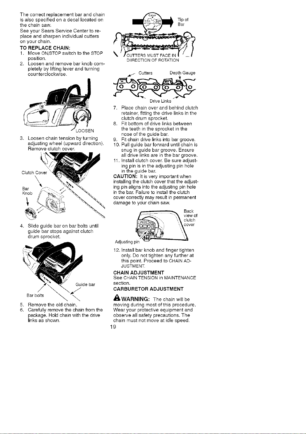
Thecorrectreplacementbarandchain
isaisospecifiedonadecaIlocatedon
thechainsaw.
SeeyourSearsServiceCentertore-
placeandsharpenindividualcutters
onyourchain.
TOREPLACECHAIN:
1. MoveON/STOPswitchtotheSTOP
position.
2. Loosenandremovebarknobcom-
pletelybyliftingteverandturning
counterclockwise.
_OOSEN
3. Loosen chain tension by turning
adjusting wheel (upward direction).
Remove ctutch cover.
,\,
Clutch Cover
\
Ear
Knob
4. Stide guide bar on bar boIts until
guide bar stops against clutch
drum sprocket.
Guide bar
Bar bolts _
5. Remove the otd chain.
6. Carefully remove the chain from the
package. Hold chain with the drive
links as shown.
DHRECTION OF ROTATION
Cutters Depth Gauge
Drive Links
7. Place chain over and behind clutch
retainer, fitting the drive links in the
clutch drum sprocket.
8. Fit bottom of drive tinks between
the teeth in the sprocket in the
nose of the guide bar.
9. Fit chain drive tinks into bar groove.
10. Pult guide bar forward until chain is
snug in guide bar groove. Ensure
all drive links are in the bar groove.
11. Install clutch cover. Be sure adjust-
ing pin is in the adjusting pin hole
in the guide bar.
CAUTION: tt is very important when
instaIling the clutch cover that the adjust-
ing pin aligns into the adjusting pin hole
in the bar. Failure to instalt the clutch
cover correctly may result in permanent
damage to your chain saw.
B ok
view of
clutch
vet
Adjusting pin
12. Install bar knob and finger tighten
only. Do not tighten any further at
this point. Proceed to CHAIN AD-
JUSTMENT.
CHAIN ADJUSTMENT
See CHAIN TENSION in MAINTENANCE
section.
CARBURETOR ADJUSTMENT
'_' WARNING: The chain wiil be
moving during most of this procedure.
Wear your protective equipment and
observe all safety precautions. The
chain must not move at idie speed.
19
The carburetor has been carefully set
at the factory. Adjustments may be
necessary if you notice any of the fol-
lowing conditions:
• Chain moves at idle. See IDLE
SPEED-T adjusting procedure.
• Saw witt not idle. See IDLE SPEED-T
adjusting procedure.
Idle Speed-T
Atlow engine to idte. If the chain moves,
idle is too fast. If the engine starts, idle is
too slow. Adjust speed until engine runs
without chain movement (idle too fast) or
stalling (idle too slow). The idle speed
screw is tocated in the area above the
primer bulb and is _abeled T.
• Turn idle screw (T) clockwise to in-
crease engine speed.
• Turn idle screw (T) counterc}ockwise
to decrease engine speed.
tf you require further assistance or are
unsure about performing this procedure,
contact your Sears Service Center or
call our customer assistance help line at
1-800-235-5878.
WARNING: Perform the follow-
ing steps after each use:
• Allow the engine to cool and secure
the unit before storing or transporting.
• Store chain saw and fuel in a well
ventitatad area where fuel vapors
cannot reach sparks or open flames
from water heaters, electric motors or
switches, furnaces, etc.
• Store chain saw with al_ guards in
place and position chain saw so that
any sharp object cannot accidentally
cause injury.
• Store chain saw well out of the reach
of chitdren.
SEASONAL STORAGE
Prepare your unit for storage at the
end of the season or if it wilt not be
used for 30 days or more,
If your chain saw is to be stored for a
period of time:
• C_ean saw thoroughly before storage.
• Store in a clean dry area.
• Lightty oil external meta_ surfaces
and guide bar.
• Oil the chain and wrap it in heavy pa-
per or ctoth.
FUEL SYSTEM
Empty the fue} system before storage
for 30 days or longer. Drain the gas
tank, start the engine and let it run until
the fuet }ines and carburetor are empty.
Use fresh fuel next season.
Under FUELING ENGINE in the OPERA-
TION section of this manual see mes-
sage tabeIed IMPORTANT regarding
the use of gasohol in your chain saw.
Fuel stabilizer is an acceptabIe alter-
native in minimizing the formation of
fuel gum deposits during storage. Add
stabilizer to the gasoline in the fueI
tank or fuel storage container,
Follow the mix instructions found on
stabilizer containers. Run engine at
least 3 minutes after adding stabilizer.
Craftsman 40:1,2-cycle engine oil (air
coo_ed) is blended with fue_ stabilizer, tf
you do not use this oil, you can add a
fuel stabilizer to your fueI tank.
ENGINE
• Remove spark pIug and pour 1 tea-
spoon of 40:1,2-cycSe engine oil (air
cooled) through the spark piug open-
ing. S_owly pull the starter rope 8 to
10 times to distribute oil.
• Replace spark p_ug with new one of
recommended type and heat range.
• Clean air filter.
• Check entire unit for loose screws,
nuts, and bolts. Replace any dam-
aged, broken, or worn parts.
• At the beginning of the next season,
use only fresh fue_ having the proper
gasoline to oil ratio.
OTHER
• Do not store gasoline from one sea-
son to another.
• Replace your gasotine can if it starts
to rust.
2O

TROUBLESHOOTING TABLE
_, WARNING: Always stop unit and disconnect spark plug before perform-
ing all of the recommended remedies below except remedies that require
operation of the unit.
TROUBLE CAUSE
Engine will not
start or will run
only a few
seconds after
starting.
Engine will
not idle
properly
Engine wilI not
accelerate,
lacks power,
or dies under
a _oad.
Engine
smokes
excessively.
Engine runs
hot.
1. ON/STOP switch in
STOP position.
2. Engine flooded.
3 Fuel tank empty.
4. Spark plug not firing.
5 Fuel not reaching
carburetor.
6 Carburetor requires
adjustment.
7 None of the above
1. Idle speed set too high
or too low.
2 Low Speed Mixture
requires adjustment.
3. Crankshaft seals worn.
4. Compression low.
5 None of the above
t. Air filter dirty.
2. Spark plug fouled.
3. Carburetor requires
adjustment.
4. Exhaust ports or muf-
fler outlets plugged.
5. Compression low
6. Chain brake engaged.
7. None of the above.
1. Choke partially on
2. Fuel mixture incorrect
3 Air filter dirty.
4 High Speed Mixture
requires adjustment.
5 Crankcase leak
1. Fuel mixture incorrect
2. Spark plug incorrect.
3 High Speed Mixture
set too lean.
4 Exhaust ports or muf-
fler outlets plugged
5 Carbon build-up on
spark arresting screen.
6 Starter housing dirty
7 None of the above
REMEDY
1. Move ON/STOP switch to ON.
2. See "Difficult Starting" in the
Operation Section.
3. Fill tank with correct fuel mixture.
4. Install new spark plug.
5. Check for dirty fuel filter; replace.
Check for kinked or split fuel line;
repair or replace.
6. Contact Sears Service (see back cover).
7. Contact Sears Service {see back cover).
1. See 'Carburetor Adjustment" in the
Service and Adjustments Section.
2 Contact Sears Service (see back cover).
3. Contact Sears Service (see back cover).
4. Contact Sears Service (see back cover).
5. Contact Sears Service (see back cover).
1. Clean or replace air flIter.
2. Clean or replace plug and regap.
3. Contact Sears Service (see back cover).
4. Contact Sears Service (see back cover).
5 Contact Sears Service (see back cover).
6 Disengage chain brake.
7 Contact Sears Service (see back cover).
1. Adjust choke.
2. Empty fuel tank and refill w_th
correct fuel mixture.
3. Clean or replace air filter.
4. Contact Sears Service (see back cover)
5. Contact Sears Service (see back cover)
1. See "Fueling Engine" in the Operation
section
2. Replace with correct plug.
3. Contact Sears Service (see back cover)
4. Contact Sears Service (see back cover)
5. Clean spark arresting screen
6. Clean starter housing area.
7. Contact Sears Service (see back cover)
Oil inadequate 1. Oil tank empty. 1. Fill oil tank.
for bar and 20i_ pump or oil filter 2. Contact Sears Service (see back cover).
chain clogged.
lubricaflon. 3. Guide bar oi_hole 3. Remove bar and clean
blocked.
Chain moves at 1. Idle speed requires t See "Carburetor Adjustment" in the
idle speed, adjustment. Service and Adjustments Section.
2. Clutch requires repair. 2 Contact Sears Service (see back cover).
21
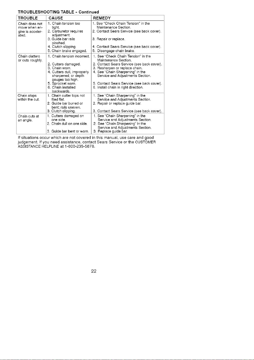
TROUBLESHOOTING TABLE - Continued
TROUBLE
Chain does not
move when en-
gine is acceler-
ated
Chain clatters
or cuts roughty.
CAUSE
t. Chain tension too
tight.
2. Carburetor requires
adjustment
3. Guide bar rails
pinched.
4-.C_utchslipping
5. Chain brake engaged.
t. Chain tension incorrect.
REMEDY
1.See "Check Chain Tension"in the
Maintenance Section
2. Contact Sears Service (see back cover)
2. Cutters damaged.
3. Chain worn
4. Cutters dulI, improperly
sharpened, or depth
gauges too high.
5. Sprocket worn.
6. Chain insta}led
backwards.
1. Chain cutter tops not
filed flat.
2 Guide bar burred or
bent; rails uneven.
3 Clutch slipping.
t Cutters damaged on
one side.
2 Chain duII on one side
3. Repair or replace.
4. Contact Sears Service (see back cover)
5. Disengage chain brake
1. See "Check Chain Tension" in the
Maintenance Section.
2 Contact Sears Service (see back cover).
3. Resharpen or replace chain.
4. See "Chain Sharpening" in the
Service and Adjustments Section.
5. Contact Sears Service (see back cover).
6 Install chain in right direction.
Chain stops 1. See "Chain Sharpening" in the
within the cut. Service and Adjustments Section.
2 Repair or replace guide bar
3. Contact Sears Service (see back cover).
Chain cuts at 1. See "Chain Sharpening" in the
an angle. Service and Adjustments Section
2. See 'Chain Sharpening" in the
Service and Adjustments Section
3 Guide bar bent or worn. 3. Replace guide bar
tf situations occur which are not covered in this manual, use care and good
judgement, tf you need assistance, contact Sears Service or the CUSTOMER
ASSISTANCE HELPUNE at t-800-235-5878,
22
YOUR WARRANTY RIGHTS AND
OBLIGATIONS: The U.S. Environ-
mental Protection Agency/California
Air Resources Board and Sears, Roe-
buck and Co., U.S.A., are pieased to
explain the emissions control system
warranty on your year 2007 and later
small off-road engine. In California, all
small off-road engines must be de-
signed, built, and equipped to meet the
State's stringent anti-smog standards.
Sears must warrant the emission con-
trot system on your small off-road en-
gine for the periods of time ]isted below
provided there has been no abuse, ne-
glect, or improper maintenance of your
small off-road engine. Your emission
control system includes parts such as
the carburetor, the ignition system and
the fuel tank (California only). Where a
warrantable condition exists, Sears witt
repair your small off-road engine en-
gine at no cost to you. Expenses cov-
ered under warranty include diagnosis,
parts and labor. MANUFACTURER'S
WARRANTY COVERAGE: If any
emissions related part on your engine
(as listed under Emissions Control
Warranty Parts List) is defective or a
defect in the materials or workmanship
of the engine causes the failure of
such an emission related part, the part
wiIt be repaired or replaced by Sears.
OWNER'S WARRANTY RESPONSI-
BILITIES: As the small off-road en-
gine engine owner, you are responsi-
ble for the performance of the required
maintenance listed in your operator's
manual. Sears recommends that you
retain all receipts covering mainte-
nance on your small off-road engine,
but Sears cannot deny warranty solely
for the lack of receipts or for your fail-
ure to ensure the performance of ait
scheduled maintenance. As the small
off-road engine engine owner, you
shouid be aware that Sears may deny
you warranty coverage if your smaIt
off-road engine engine or a part of it
has failed due to abuse, negIect, im-
proper maintenance, unapproved modifi-
cations, or the use of parts not made or
approved by the original equipment
manufacturer
You are responsible for presenting your
small off-road engine to a Sears autho-
rized repair center as soon as a problem
exists. Warranty repairs should be com-
pleted in a reasonabie amount of time,
not to exceed 30 days. If you have any
questions regarding your warranty rights
and responsibilities, you shouid contact
your nearest authorized service center
or caiI Sears at 1-800-469-4683. WAR-
RANTY COMMENCEMENT DATE: The
warranty period begins on the date the
small off-road engine is purchased.
LENGTH OF COVERAGE: This war-
rarity shall be for a period of two years
_om the initiaI date of purchase. WHAT
IS COVERED: REPAIR OR REPLACE-
MENT OF PARTS. Repair or replace-
ment of any warranted part will be per-
formed at no charge to the owner at an
approved Sears Service Center. If you
have any questions regarding your war-
ranty rights and responsibilities, you
should contact your nearest authorized
service center or call Sears at
1-800-469-4663. WARRANTY PERIOD:
Any warranted part which is not
scheduled for repIacement as required
maintenance, or which is scheduled only
for regular inspection to the effect of
"repair or reptace as necessary" shall be
warranted for 2 years. Any warranted
part which is scheduled for replacement
as required maintenance shall be war-
ranted for the period of time up to the
first scheduled replacement point for that
part. DIAGNOSIS: The owner shai] not
be charged for diagnostic labor which
leads to the determination that a war-
ranted part is defective if the diagnostic
work is performed at an approved Sears
Service Center. CONSEQUENTIAL
DAMAGES: Sears may be tiable for
damages to other engine components
caused by the failure of a warranted part
still under warranty. WHAT IS NOT
COVERED: All failures caused by
abuse, neglect, or improper mainte-
nance are not covered. ADD-ON OR
MODIFIED PARTS: The use of add-on
or modified parts can be grounds for dis-
altowJng a warranty claim. Sears is not
liable to cover faiIures of warranted parts
caused by the use of add-on or modi-
fied parts.
23
HOWTOFILE A CLAIM: If you have
any questions regarding your warranty
rights and responsibilities, you shoutd
contact your nearest authorized ser-
vice center or calt Sears at
1-800-469-4683. WHERE TO GET
WARRANTY SERVICE: Warranty ser-
vices or repairs shatt be provided at att
Sears Service Centers. CaIt
1-800-469-4683. MAINTENANCE,
REPLACEMENT AND REPAIR OF
EMISSION RELATED PARTS: Any
Sears approved replacement part
used in the performance of any war-
ranty maintenance or repair on emis-
sion related parts will be provided with-
out charge to the owner if the part is
under warranty. EMISSION CONTROL
WARRANTY PARTS LIST: spark pIug
(covered up to maintenance sched-
ule), ignition module, muffler including
catalyst (if equipped), fuel tank (Calf
fornia onty). MAINTENANCE STATE-
MENT: The owner is responsible for
the performance of all required mainte-
nance as defined in the operator's
manual,
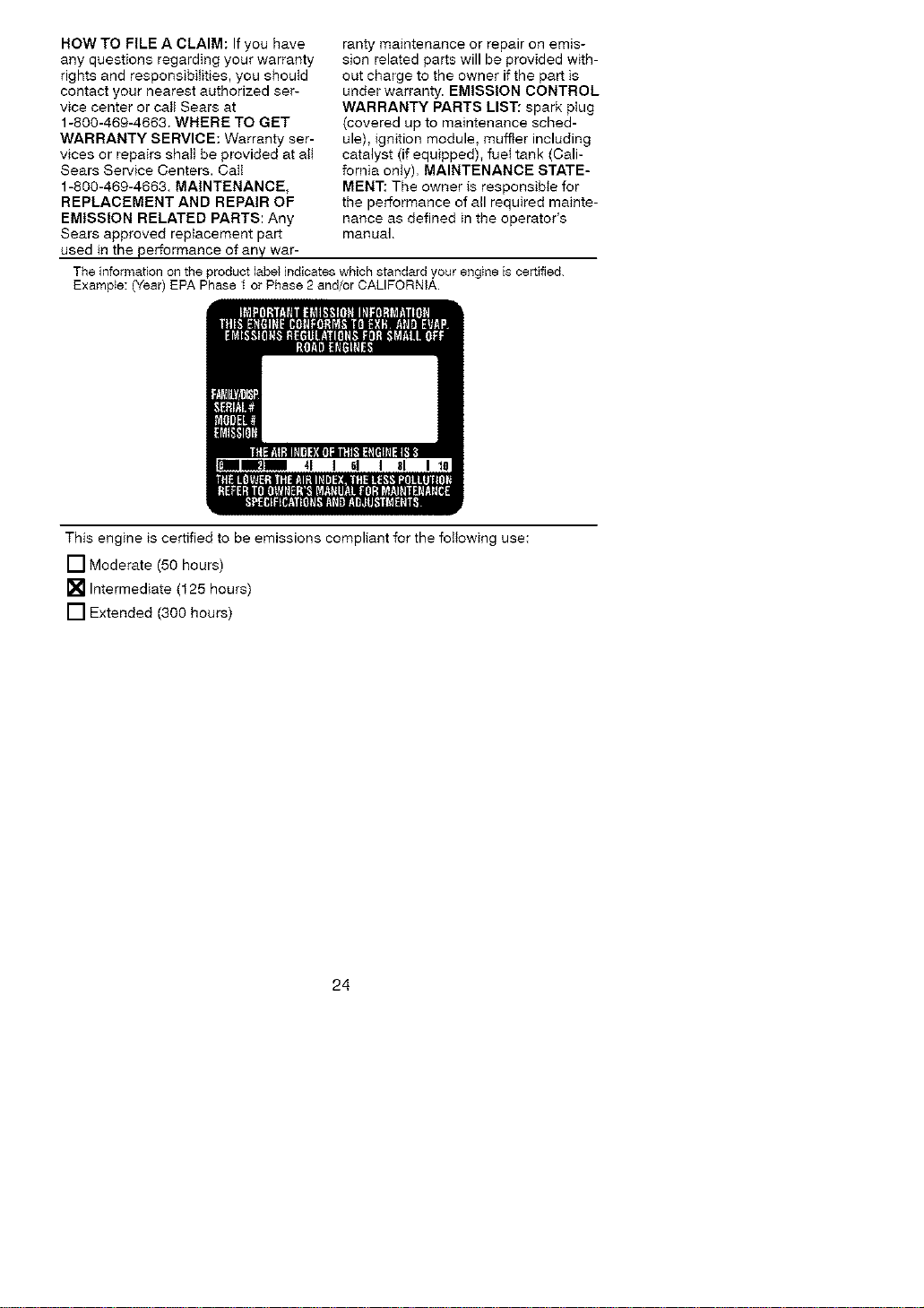
The information onthe product label indicates which standard your engine is certified.
Example: (Year) EPA Phase t or Phase 2 and/or CALIFORNIA.
41 61 I 81 I
This engine is certified to be emissions compliant for the following use:
[] Moderate (50 hours)
[] Intermediate (125 hours)
[] Extended (300 hours)
24
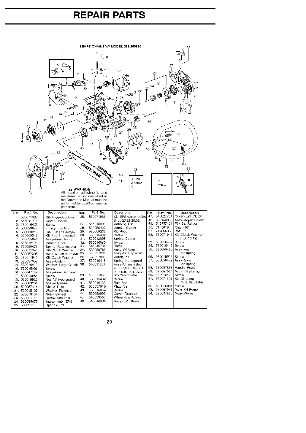
REPAIR PARTS
8EARS CHA_NSAW MODEL 358350880
5 ,
27
29
47
46
48
_1 WARNING
All repairs, ad}ustments and
60
52 58 611
maintenance _3oL described in
the Operator's Manual must be
pelfolmed by qualified Bentice
pe_sonne!.
Fief Part No Description Fief¸ Part No
1 530071927 Kit Tngger/Looko_t 26 530071966
2 545011906 Covel Hand!e
3 530016433 Sclew 27 545045901
4 580023877 Fitting Fuelline 2B 530056402
5 580069216 Kit Fuel fine (Earge) 29 580069232
6 580069247 Kit Fuel line (smal] / 80 530016432
7 530095646 Assy Fue_ p]ok up 31• 530042095
8 545012106 Handle Rear 32 530016080
9 580059475 Spring Rear isoEatol 33 545045701
!0 530071945 Kit OlutchWashel 34 530058786
11 530057905 Ashy oiutch d_m 3/_ 35 530057236
12 530071945 Kit OlutchWashel 36 530057880
13 530057907 Assy Olutch 37 530016416
14 530016419 Washe[ LargeC_u_ 38 545011801
!5 530015906 S_lew
!6 580047192 Ashy Fue_Oapwret
!7 530016064 Sciew 39 530071893
18 530015922 Nut "U'_typespeed 40 530016432
19 530039231 Assy Flywheel 41 530016133
20 530057911 Shield Heat 42 530057910
21 530015127 Washer Flywhee! 43 530016064
22 530016134 Nut F_ywheel 44 530059999
23 530021179 Screw Shoulder 45 545039503
24 530059677 Starte[ Hub EPS 46 545040604
25 530021180 Spring EPS
Description
Kit EPS starter pulse
(lncl 23,24,25,32)
Housing Fan
Handle Stalter
Kit Rope
Sorew
Spring Starter
Screw
B_ffle
Assy Oil Vent
Assy Oil Cap w/ret
Handguar6
Spdng Handgua_
Assy Chassi_ (Incl
4,5,6,7,9,15,16,17,18
20,84,35_37,41,57)
Kit Chainblake
ScFew
Bolt Bar
p!ate 8al
Screw
Cover Gearbox
Whoo] Bar Adiust
Assy EZT Knob
Ret Part NO. Description
4[ 54bU2/[01 Cover LZl'Clutch
48 530150000 Assy A_ustSorew
49 545157401 Pin BarAd}ust
50 71 8619 Chain 18 _
51 71 36638 Bar18"
52 530071945 Kit CIutchWasher
(]nol 10,12)
53 530016432 Screw
54 530016443 Screw
55 530059480 Assy real
rso spring
56 530015906 Screw
57 530059479 Assy flont
iso spling
58 5_0057878 Har_d_e Front
59 530057924 Assy Oil pick up
60 530016432 Screw
61 530071891 Kit O]lpump
{Encl 62,63 64)
62 530016064 Screw
63 530057931 Ashy Oil Pump
64 530037820 Gear Worm
25
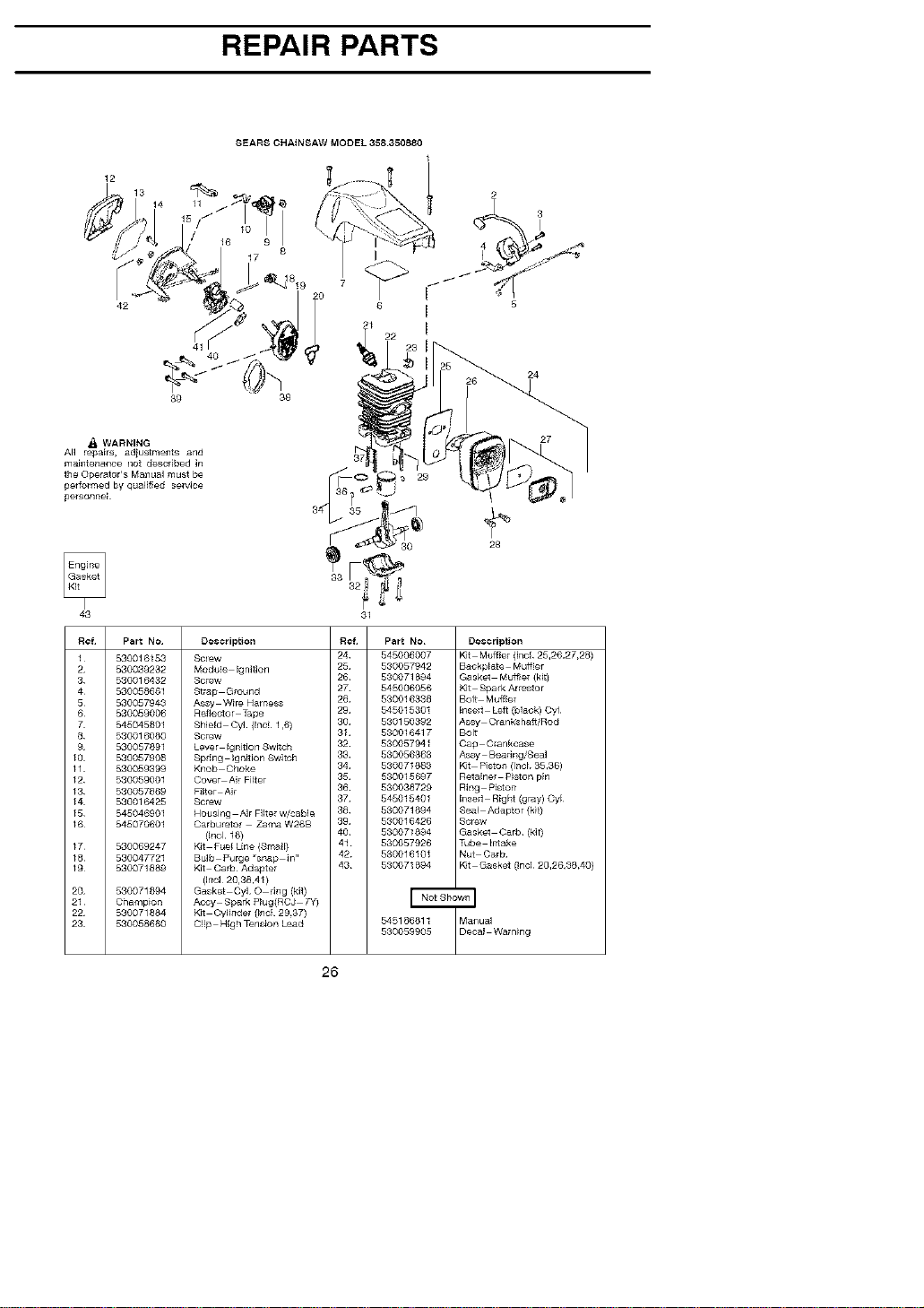
REPAIR PARTS
12
42
SEARS CHAt NSAW MODEL 358350880
1
i- I
/ 8 ¢o !
8
17
7
6
21
24
39 38
WARNING
All repairs, ad}ustments and
maintenance not described in
the Operator's M_nual must be
pelfolmed by qualified sewice
pe_sonneE
28
43
Ref part No
1
2
8
4
5
6
7
8
9
10
11
12
18
14
15
16
17
18
19
20
21
22
23
530016153
530099232
530016432
530058661
530057943
530059006
545045801
580016060
530057891
530057908
590059399
580059001
580057869
580016425
545046901
545070601
530069247
530047721
580071889
530071894
Champion
530071884
530058660
Description
SOFW
Modu!e Ignition
Screw
Strap Ground
A_ wire Hamess
Rofleclor [ape
Shield CyL {Inc! 1,6)
Sorew
Lever Igni_on Sw_tch
Spring Ignition Switoh
Knob Clnoke
Cover Air Filter
Filter Ai/
Screw
Housi_ Air Filte_ w/cable
Oarburetor Zama W26B
(_nd !6}
Kit Fuel Line (Small)
Bulb purge "snap i_"
Kit Carl3 Adapter
(Incl 20,38,41}
Gasket CyL O dng (kit)
Accy Spalk Plug(RCJ 7_
Kit Cylinde_ _nc! 29,37)
C!ip High T_nsfon Lead
Ref Part NO
24 545006007
25 530057942
26 580071694
27 545006056
28 530016.388
29 545015301
80 530150392
31 530016417
82 530057941
33 530056863
84 53007!8_
35 530015_7
86 530038729
87 545015401
38 530071694
89 530016426
40 530071894
41 530057926
42 530016101
43 530071894
545186811
530059905
Description
Kit Muff_el (Incl 25,26,27,28)
Baokplate Mu_ff(er
Gasket Mu_lel (kit}
Kit Spark Arre_or
Bolt Mufflel
1_se_l Left (blac© Oyl
Assy Cran_hafi/Rod
Bolt
Cap C_nkcase
As_ Bealing/Sea_
Kit pisto_ (IncL 35,36)
R_ainel Piton pin
Ring Piton
I_seri Right (gray) Cyl
Seal Adaptor {kit}
Screw
Gasket Ca_ (kit}
Tube Intake
Nut Oarb
K_t Gaskot (IncL 20,26,38,40)
Manua_
Decal Warning
26

