Owner's Manual
ICRIIFTSMIIN° _OWE R
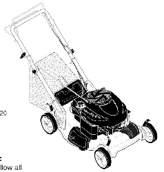
ROTARYLAWN
4.0 Horsepower
20" Side Discharge
Model No.
917.386082
CAUTION:
Read and follow all
Safety Rules and Instructions
before operating this equipment
Sears, Roebuck and Co., Hoffman Estates, IL 60179
Visit our Craftsman website: www.sears.com/craftsman
U.S.A.
Warranty ................................................. 2
Safety Rules ........................................ 2-4
Assembly / Pre-Operation ................... 4-8
Operation ........................................... 9-11
Maintenance Schedule ........................ 12
Maintenance .................................... 12-15
Product Specifications .......................... 13
Service and Adjustments ...................... 15
Storage ............................................ 16-17
Troubleshooting .............................. 17-18
Repair Parts ..................................... 36-41
SearsmService ......................... Back Cover
LIMITED ONE YEAR WARRANTY ON CRAFTSMAN POWER MOWER
For one year from date of purchase, when this Craftsman Lawn Mower is maintained,
lubricated, and tuned up according to the operating and maintenance instructions in
the owner's manual, Sears will repair free of charge any defect in material or workman-
ship.
If this Craftsman Lawn Mower is used for commercial or rental purposes, this warranty
applies for only 90 days from the date of purchase.
This Warranty does not cover:
• Expendable items which become worn during normal use, such as rotary mower
blades, blade adapters, belts, air cleaners and spark plug.
• Repairs necessary because of operator abuse or negligence, including bent
crankshafts and the failure to maintain the equipment according to the instructions
contained in the owner's manual.
Warranty service is available by returning the Craftsman power mower to the nearest
Sears Service Center/Department in the United States. This warranty applies only
while this product is used in the United States.
This Warranty gives you specific legal rights, and you may also have other rights which
vary from state to state.
SEARS, ROEBUCKAND CO., D/817 WA, HOFFMAN ESTATES, ILLINOIS 60179
IMPORTANT: This cutting machine is capable of amputating hands and feet and
throwing objects. Failure to observe the following safety instructions could result in
serious injury or death.
&Look for this symbol to point out
important safety precautions. It means
CAUTION!!! BECOMEALERTH[ YOUR
SAFETY IS INVOLVED.
A WARNING: In order to prevent
accidental starting when setting up,
transporting, adjusting or making repairs,
always disconnect spark plug wire and
place wire where it cannot contact spark
plug.
_,WARNING: Battery posts, terminals and
related accessories contain lead and
lead compounds, chemicals known to the
State of California to cause cancer and
birth defects or other reproductive harm.
Wash hands after handling.
AWARNING: Engine exhaust, some of
its constituents, and certain vehicle _J._' .
components contain or emit chemicals
known to the State of California to cause
cancer and birth defects or other repro-
ductive harm.
2
_, CAUTION: Muffler and other engine
parts become extremely hot during
operation and remain hot after engine
has stopped. To avoid severe burns on
contact, stay away from these areas.
I. GENERAL OPERATION
• Read, understand, and follow all
instructions on the machine and in the
manual(s) before starting. Be thor-
oughly familiar with the controls and
the proper use of the machine before
starting.
• Do not put hands or feet near or under
rotating parts. Keep clear of the
discharge opening at all times.
• Only allow responsible individuals,
who are familiar with the instructions, to
operate the machine.
• Clear the area of objects such as
rocks, toys, wire, bones, sticks, etc.,
which could be picked up and thrown
by the blade.
• Be sure the area is clear of other
people before mowing. Stop machine if
anyone enters the area.
• Do not operate the mower when
barefoot or wearing open sandals.
Always wear substantial foot wear.
• Do not pull mower backwards unless
absolutely necessary. Always look
down and behind before and while
moving backwards.
• Do not operate the mower without
proper guards, plates, grass catcher or
other safety protective devices in place.
• See manufacturer's instructions for
proper operation and installation of
accessories. DO NOT use accessories
that are not recommended by the
manufacturer of your mower, such as
de-thatcher blade attachments, which
can be hazardous and damage the
mower.
• Stop the blade(s) when crossing gravel
drives, walks, or roads.
• Stop the engine (motor) whenever you
leave the equipment, before cleaning
the mower or unclogging the chute.
• Shut the engine (motor) off and wait
until the blade comes to complete stop
before removing grass catcher.
• Mow only in daylight or good artificial
light.
• Do not operate the machine while
under the influence of alcohol or drugs.
• Never operate machine in wet grass.
Always be sure of your footing: keep a
firm hold on the handle and walk; never
run.
• Disengage the self-propelled mecha-
nism or drive clutch on mowers so
equipped before starting the engine
(motor).
• If the equipment should start to vibrate
abnormally, stop the engine (motor)
and check immediately for the cause.
Vibration is generally a warning of
trouble.
• Always wear safety goggles or safety
glasses with side shields when operat-
ing mower.
II. SLOPE OPERATION
Slopes are a major factor related to slip
and fall accidents which can result in
severe injury. All slopes require extra
caution. If you feel uneasy on a slope, do
not mow it.
DO:
• Mow across the face of slopes: never
up and down. Exercise extreme caution
when changing direction on slopes.
• Remove obstacles such as rocks, tree
limbs, etc.
• Watch for holes, ruts, or bumps. Tall
grass can hide obstacles.
DO NOT:
• Do not trim near drop-offs, ditches or
embankments. The operator could lose
footing or balance.
• Do not trim excessively steep slopes.
• Do not mow on wet grass. Reduced
footing could cause slipping.
II1.CHILDREN
Tragic accidents can occur if the operator
is not alert to the presence of children.
Children are often attracted to the
machine and the mowing activity. Never
assume that children will remain where
you last saw them.
• Keep children out of the trimming area
and under the watchful care of another
responsible adult.
• Be alert and turn machine off if children
enter the area.
• Before and while walking backwards,
look behind and down for small
children.
• Never allow children to operate the
machine.
• Use extra care when approaching blind
corners, shrubs, trees, or other objects
that may obscure vision.
3
IV. SERVICE
• Use extra care in handling gasoline
and other fuels. They are flammable
and vapors are explosive.
-Use only an approved container.
- Never remove gas cap or add fuel
with the engine running. Allow
engine to cool before refueling. Do
not smoke.
-Never refuel the machine indoors.
- Never store the machine or fuel
container inside where there is an
open flame, such as a water heater.
• Never run a machine inside a closed
area.
• Never make adjustments or repairs
with the engine (motor) running.
Disconnect the spark plug wire, and
keep the wire away from the plug to
prevent accidental starting.
• Keep nuts and bolts, especially blade
attachment bolts, tight and keep
equipment in good condition.
• Never tamper with safety devices.
Check their proper operation regularly.
• Keep machine free of grass, leaves, or
other debris build-up. Clean oil or fuel
spillage. Allow machine to cool before
storing.
• Stop and inspect the equipment if you
strike an object. Repair, if necessary,
before restarting.
• Never attempt to make Wheel height
adjustments while the engine (motor) is
running.
• Grass catcher components are subject
to wear, damage, and deterioration,
which could expose moving parts or
allow objects to be thrown. Frequently
check components and replace with
manufacturer's recommended parts,
when necessary.
• Mower blades are sharp and can cut.
Wrap the blade(s) or wear gloves, and
use extra caution when servicing them.
• Do not change the engine governor
setting or overspeed the engine.
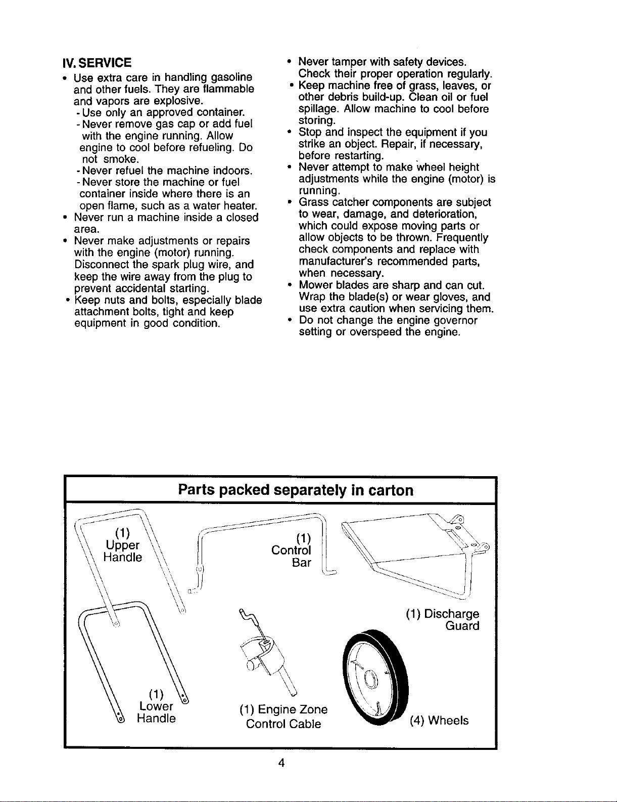
(1)
\
(1
Lower
Handle
Parts packed separately in carton
f/ ControlLI
Bar
(1) Engine Zone
Control Cable
(1) Discharge
Guard
(4) Wheels
4
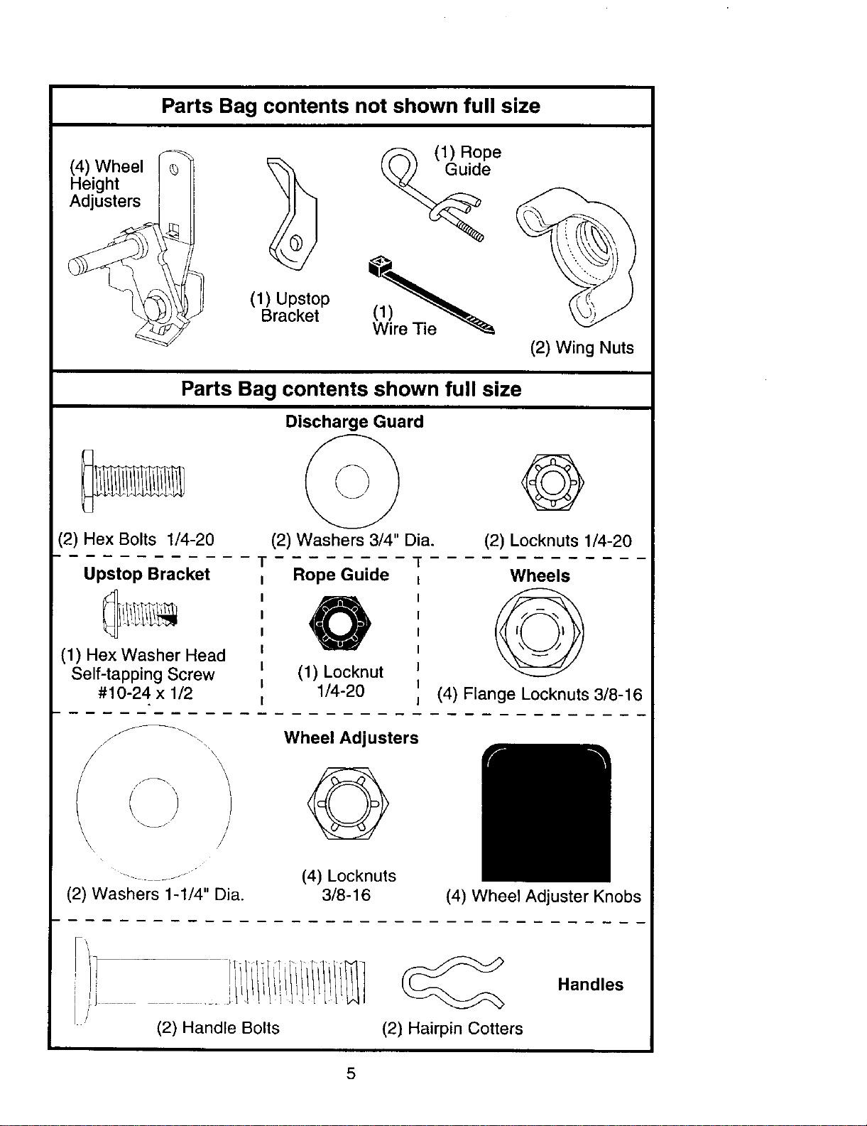
Parts Bag contents not shown full size
(4) Wheel
Height
Adjusters
(1) Upstop
Bracket
(_e(1) Rope
(2) Wing Nuts
Parts Bag contents shown full size
(2) Hex Bolts 1/4-20
T
Upstop Bracket
(1) Hex Washer Head
Self-tapping Screw
#10-24 x 1/2
Discharge Guard
(2) Washers 3/4" Dia.
©
(2) Locknuts 1/4-20
Rope Guide
(1) Locknut
1/4-20
Wheels
(4) Flange Locknuts 3/8-16
\
\
"_J J
(2) Washers 1-1/4" Dia.
Wheel Adjusters
(4) Locknuts
3/8-16
(4) Wheel Adjuster Knobs
(2) Handle Bolts (2) Hairpin Cotters
Handles
5
_I,CAUTION: Do not operate this mower
without the discharge guard or an entire
approved grass catcher in place. These
guards are for your protection and are
required by the American National
Standards Institute and Consumer
Products Safety Commission.
_CAUTION" Disconnect spark plug wire
from spark plug and place wire where it
cannot come in contact with plug.
Read these instructions and this manual
in its entirety before you attempt to
assemble or operate your new lawn
mower.
IMPORTANT: This lawn mower is
shipped WITHOUT OIL OR GASOLINE in
the engine.
Your new lawn mower has been as-
sembled at the factory with the exception
of those parts left unassembled for
shipping purposes. All parts such as nuts,
washers, bolts, etc., necessary to com-
plete the assembly have been placed in
the parts bag. To ensure safe and proper
operation of your lawn mower, all parts
and hardware you assemble must be
tightened securely. Use the correct tools
as necessary to ensure proper tightness.
TOOLS REQUIRED FOR ASSEMBLY
A socket wrench set will make assembly
easier. Standard wrench sizes are listed.
(1) 5/16" Wrench (1) Adjustable Wrench
(1) 7/16" Wrench (1) 9/16" Wrench
(1) 1/2" Wrench (1) 3/4" Wrench
When right hand or left hand is men-
tioned in this manual, it means when you
are standing in the operating position,
behind the handle.
UNPACK CARTON
1. Remove all loose parts from carton.
2. Examine all items. Compare with list
of unassembled parts and hardware.
3. Remove lawn mower housing with
care. Avoid touching blade under
housing. Always wear gloves or other
protection when working under or
lifting mower.
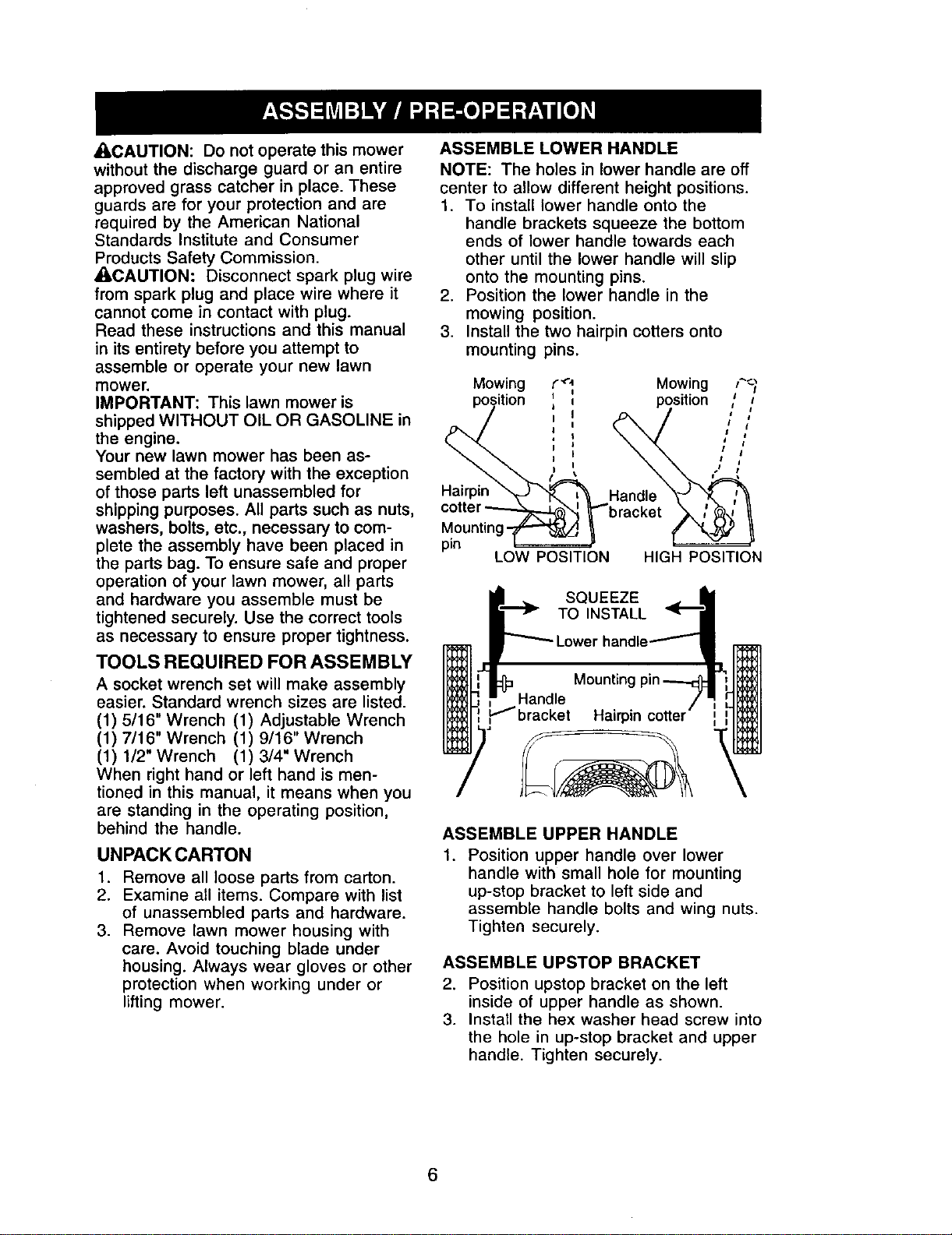
ASSEMBLE LOWER HANDLE
NOTE: The holes in lower handle are off
center to allow different height positions.
1. To install lower handle onto the
handle brackets squeeze the bottom
ends of lower handle towards each
other until the lower handle will slip
onto the mounting pins.
2. Position the lower handle in the
mowing position.
3. Install the two hairpin cotters onto
mounting pins.
Mowing
position
Hairpin
Mounting-
pin
LOW POSITION
C""_ Mowing F_
', position ;
, /
I
HIGH POSITION
SQUEEZE
TO INSTALL "_
handle_
Mountingpin -_
Hairpin cotter
ASSEMBLE UPPER HANDLE
1. Position upper handle over lower
handle with small hole for mounting
up-stop bracket to left side and
assemble handle bolts and wing nuts.
Tighten securely.
ASSEMBLE UPSTOP BRACKET
2. Position upstop bracket on the left
inside of upper handle as shown.
3. Install the hex washer head screw into
the hole in up-stop bracket and upper
handle. Tighten securely.
6
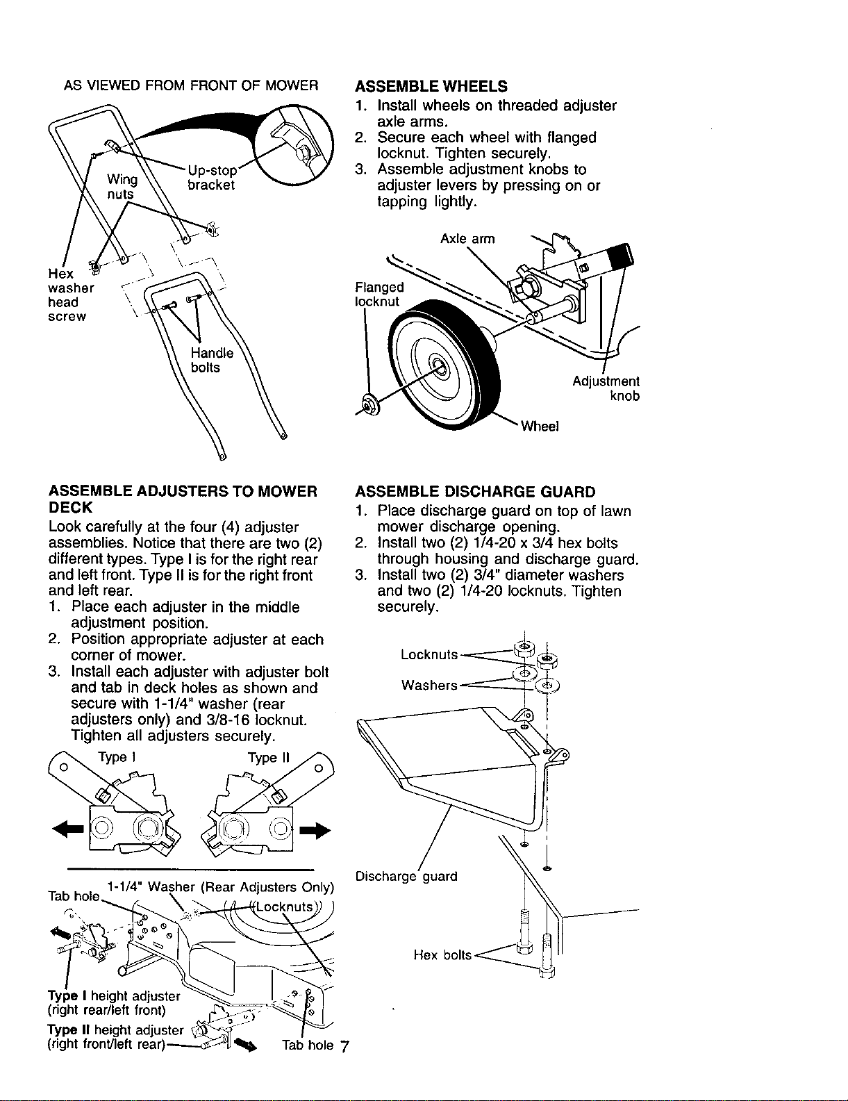
AS VIEWED FROM FRONT OF MOWER
ASSEMBLE WHEELS
1. Install wheels on threaded adjuster
axle arms.
2. Secure each wheel with flanged
Iocknut, Tighten securely,
3. Assemble adjustment knobs to
adjuster levers by pressing on or
tapping lightly.
Hex
washer
head
screw
Flanged
Iocknut
Axle arm
\
Adjustment
knob
Wheel
ASSEMBLE ADJUSTERS TO MOWER
DECK
Look carefully at the four (4) adjuster
assemblies. Notice that there are two (2)
different types. Type I is for the right rear
and left front. Type II is for the right front
and left rear.
1. Place each adjuster in the middle
.
3.
adjustment position.
Position appropriate adjuster at each
corner of mower.
Install each adjuster with adjuster bolt
and tab in deck holes as shown and
secure with 1-1/4" washer (rear
adjusters only) and 3/8-16 Iocknut.
Tighten all adjusters securely.
Type II
1-1/4" Washer (Rear Adjusters Only)
Tab hole
Type I height_ter _._ )
(right rear/left front) _'_/_--_ _ I
Type II height adjuster _'_°-- _"
(right front]left rear)_J _, Tab hole 7
ASSEMBLE DISCHARGE GUARD
1. Place discharge guard on top of lawn
mower discharge opening.
2. Install two (2) 1/4-20 x 3/4 hex bolts
through housing and discharge guard.
3. Install two (2) 3/4" diameter washers
and two (2) 1/4-20 Iocknuts. Tighten
securely.
Washers
Discharge guard
Hex
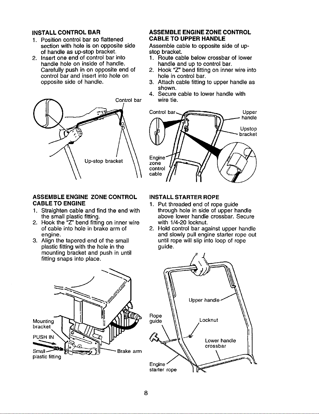
INSTALL CONTROL BAR
1. Position control bar so flattened
section with hole is on opposite side
of handle as up-stop bracket.
2. Insert one end of control bar into
handle hole on inside of handle.
Carefully push in on opposite end of
control bar and insert into hole on
opposite side of handle.
Control bar
Up-stop bracket
ASSEMBLEENGINEZONECONTROL
CABLE TO UPPER HANDLE
Assemble cable to opposite side of up-
stop bracket.
1. Route cable below crossbar of lower
handle and up to control bar.
2. Hook "Z" bend fitting on inner wire into
hole in control bar.
3. Attach cable fitting to upper handle as
shown.
4. Secure cable to lower handle with
wire tie.
Control Upper
Upstop
zone
control
cable
ASSEMBLE ENGINE ZONE CONTROL
CABLE TO ENGINE
1. Straighten cable and find the end with
the small plastic fitting.
2. Hook the "Z" bend fitting on inner wire
of cable into hole in brake arm of
engine.
3. Align the tapered end of the small
plastic fitting with the hole in the
mounting bracket and push in until
fitting snaps into place.
INSTALL STARTER ROPE
1. Put threaded end of rope guide
through hole in side of upper handle
above lower handle crossbar. Secure
with 1/4-20 Iocknut.
2. Hold control bar against upper handle
and slowly pull engine starter rope out
until rope will slip into loop of rope
guide.
Mounting
bracket
PUSH IN_
Rope
guide
plastic fitting
arm
Engine
starter rope
8
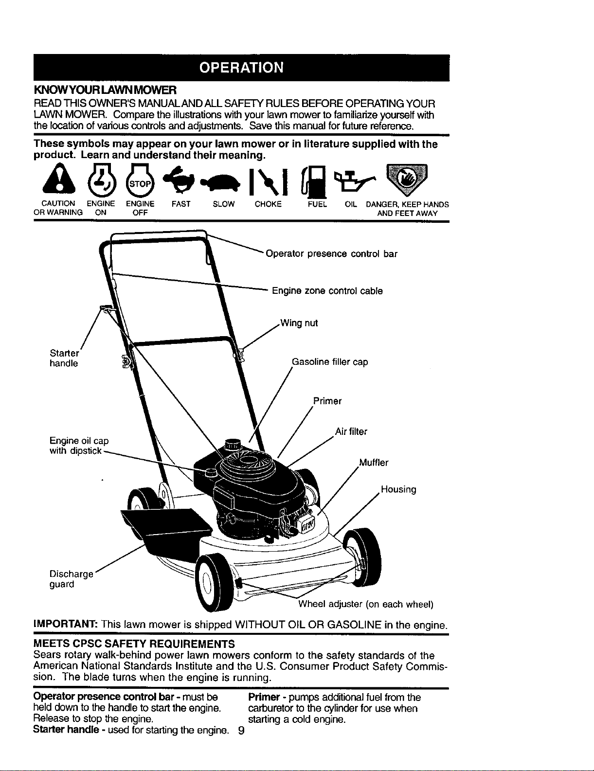
KNOWYOUR LAWN MOWER
READ THIS OWNER'S MANUAL AND ALL SAFETY RULES BEFORE OPERATING YOUR
LAWN MOWER. Compare the illustrations with your lawn mower to familiarize yourself with
the location of various controls and adjustments. Save this manual for future reference.
These symbols may appear on your lawn mower or in literature supplied with the
product. Learn and understand their meaning.
CAUTION ENGINE ENGINE FAST SLOW CHOKE FUEL OIL DANGER, KEEP HANDS
OR WARNING ON OFF AND FEET AWAY
"Operator presence control bar
Engine zone control cable
nut
Starter
handle Gasoline filler cap
Primer
Air filter
Engine oil cap
with
Muffler
Discharge
guard
Wheel adjuster (on each wheel)
IMPORTANT: This lawn mower is shipped WITHOUT OIL OR GASOLINE in the engine.
MEETS CPSC SAFETY REQUIREMENTS
Sears rotary walk-behind power lawn mowers conform to the safety standards of the
American National Standards Institute and the U.S. Consumer Product Safety Commis-
sion. The blade turns when the engine is running.
Operator presence control bar - must be
held down to the handle to start the engine.
Release to stop the engine.
Starter handle - used for starting the engine.
Primer - pumps additional fuel from the
carburetor to the cylinder for use when
starting a cold engine.
9
Theoperation of any lawn
mower can result in foreign
objects thrown into the
eyes, which can result in
severe eye damage.
Always wear safety glasses or eye
shields while operating your lawn mower
or performing any adjustments or repairs.
We recommend a standard safety
glasses or wide vision safety mask worn
over spectacles.
ENGINE SPEED
The engine speed was set at the factory
for optimum performance. Speed is not
adjustable.
ENGINE ZONE CONTROL
ACAUTION: Federal regulations require
an engine control to be installed on this
lawn mower in order to minimize the risk
of blade contact injury. Do not under any
circumstances attempt to defeat the
function of the operator control. The blade
tums when the engine is running.
• Your lawn mower is equipped with an
operator presence control bar which
requires the operator to be positioned
behind the lawn mower handle to start
and operate the lawn mower.
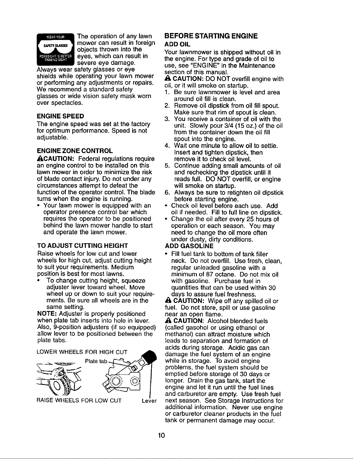
TO ADJUST CUTTING HEIGHT
Raise wheels for low cut and lower
wheels for high cut, adjust cutting height
to suit your requirements. Medium
position is best for most lawns.
• To change cutting height, squeeze
adjuster lever toward wheel. Move
wheel up or down to suit your require-
ments. Be sure all wheels are in the
same setting.
NOTE: Adjuster is properly positioned
when plate tab inserts into hole in lever.
Also, 9-position adjusters (if so equipped)
allow lever to be positioned between the
plate tabs.
LOWER WHEELS FOR HIGH CUT
Plate tal
RAISE WHEELS FOR LOW CUT Lever
BEFORE STARTING ENGINE
ADD OIL
Your lawnmower is shipped without oil in
the engine. For type and grade of oil to
use, see "ENGINE" in the Maintenance
section of this manual.
A CAUTION: DO NOT overfill engine with
oil, or it will smoke on startup.
1. Be sure lawnmower is level and area
around oil fill is clean.
2. Remove oil dipstick from oil fill spout.
Make sure that rim of spout is clean.
3. You receive a container of oil with the
unit. Slowly pour 3/4 (15 oz.) of the oil
from the container down the oil fill
spout into the engine.
4. Wait one minute to allow oil to settle.
Insert and tighten dipstick, then
remove it to check oil level.
5. Continue adding small amounts of oil
and rechecking the dipstick until it
reads full. DO NOT overfill, or engine
will smoke on startup.
6. Always be sure to retighten oil dipstick
before starting engine.
• Check oil level before each use. Add
oil if needed. Fill to full line on dipstick.
• Change the oil after every 25 hours of
operation or each season. You may
need to change the oil more often
under dusty, dirty conditions.
ADD GASOLINE
• Fill fuel tank to bottom of tank filler
neck. Do not overfill. Use fresh, clean,
regular unleaded gasoline with a
minimum of 87 octane. Do not mix oil
with gasoline. Purchase fuel in
quantities that can be used within 30
days to assure fuel freshness.
_1,CAUTION: Wipe off any spilled oil or
fuel. Do not store, spill or use gasoline
near an open flame.
_, CAUTION: Alcohol blended fuels
(called gasohol or using ethanol or
methanol) can attract moisture which
leads to separation and formation of
acids during storage. Acidic gas can
damage the fuel system of an engine
while in storage. To avoid engine
problems, the fuel system should be
emptied before storage of 30 days or
longer. Drain the gas tank, start the
engine and let it run until the fuel lines
and carburetor are empty. Use fresh fuel
next season. See Storage Instructions for
additional information. Never use engine
or carburetor cleaner products in the fuel
tank or permanent damage may occur.
10
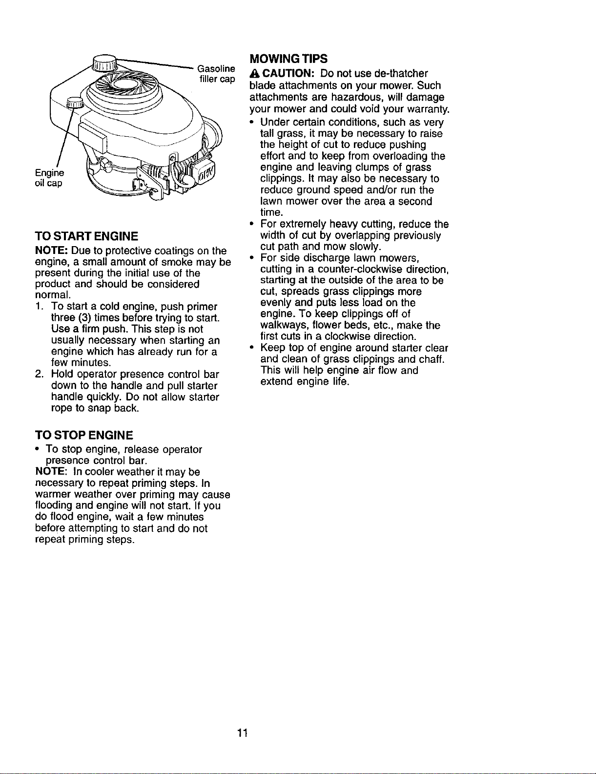
Gasoline
filler cap
Engine
oil cap
TO START ENGINE
NOTE: Due to protective coatings on the
engine, a small amount of smoke may be
present during the initial use of the
product and should be considered
normal.
1. To start a cold engine, push primer
three (3) times before trying to start.
Use a firm push. This step is not
usually necessary when starting an
engine which has already run for a
few minutes.
2. Hold operator presence control bar
down to the handle and pull starter
handle quickly. Do not allow starter
rope to snap back.
MOWING TIPS
CAUTION: Do not use de-thatcher
blade attachments on your mower. Such
attachments are hazardous, will damage
your mower and could void your warranty.
• Under certain conditions, such as very
tall grass, it may be necessary to raise
the height of cut to reduce pushing
effort and to keep from overloading the
engine and leaving clumps of grass
clippings. It may also be necessary to
reduce ground speed and/or run the
lawn mower over the area a second
time.
• For extremely heavy cutting, reduce the
width of cut by overlapping previously
cut path and mow slowly.
• For side discharge lawn mowers,
cutting in a counter-clockwise direction,
starting at the outside of the area to be
cut, spreads grass clippings more
evenly and puts less load on the
engine. To keep clippings off of
walkways, flower beds, etc., make the
first cuts in a clockwise direction.
• Keep top of engine around starter clear
and clean of grass clippings and chaff.
This will help engine air flow and
extend engine life.
TO STOP ENGINE
• To stop engine, release operator
presence control bar.
NOTE: In cooler weather it may be
necessary to repeat priming steps. In
warmer weather over priming may cause
flooding and engine will not start. If you
do flood engine, wait a few minutes
before attempting to start and do not
repeat priming steps.
11
MAINTENANCE
FILL IN DATES
AS YOU COMPLETE
REGULAR SERVICE
DATES
Check for Loose Fasteners _
Clean/Inspect Grass Catcher
(If Equipped) If _'
M Clean Lawn Mower i/
O Clean Under Drive Cover
(Power-Propelled Mowers) I_
Check ddve belt/pulleys
E (Power-Propelled Mowers) If
Check/Sharpen/Replace Stade If 3
Lubrication Chart If
Clean Battew/Recharga
IEtectric Start Mowers! V'
E Check EngineOil Level
N Change Engine Oil tfl,2
G Clean Air Filter I_ 2
I InspectMuffler _,/
N Clean or Replace Spark Plug
E Replace Air FilterPaper Cartridge _2
v'
i/,
1 * Change more often when operating under a heavy load or in high ambient temperatures.
2 - Service more often when operaSng in dirty or dusty conditions,
3 - Replace blades more often when mowing in sandy soil.
4 - Charge 48 hours at end of season.
GENERAL RECOMMENDATIONS
The warranty on this lawn mower does not
cover items that have been subjected to
operator abuse or negligence. To receive full
value from the warranty, operator must
maintain mower as instructed in this manual.
Some adjustments will need to be made
periodically to properly maintain your unit.
All adjustments in the Service and Adjust-
ments section of this manual should be
checked at least once each season.
• Once a year, replace the spark plug, clean
or replace air filter element and check
blade for wear. A new spark plug and
clean/new air filter element assure proper
air-fuel mixture and help your engine run
better and last longer.
• Follow the maintenance schedule in this
manual.
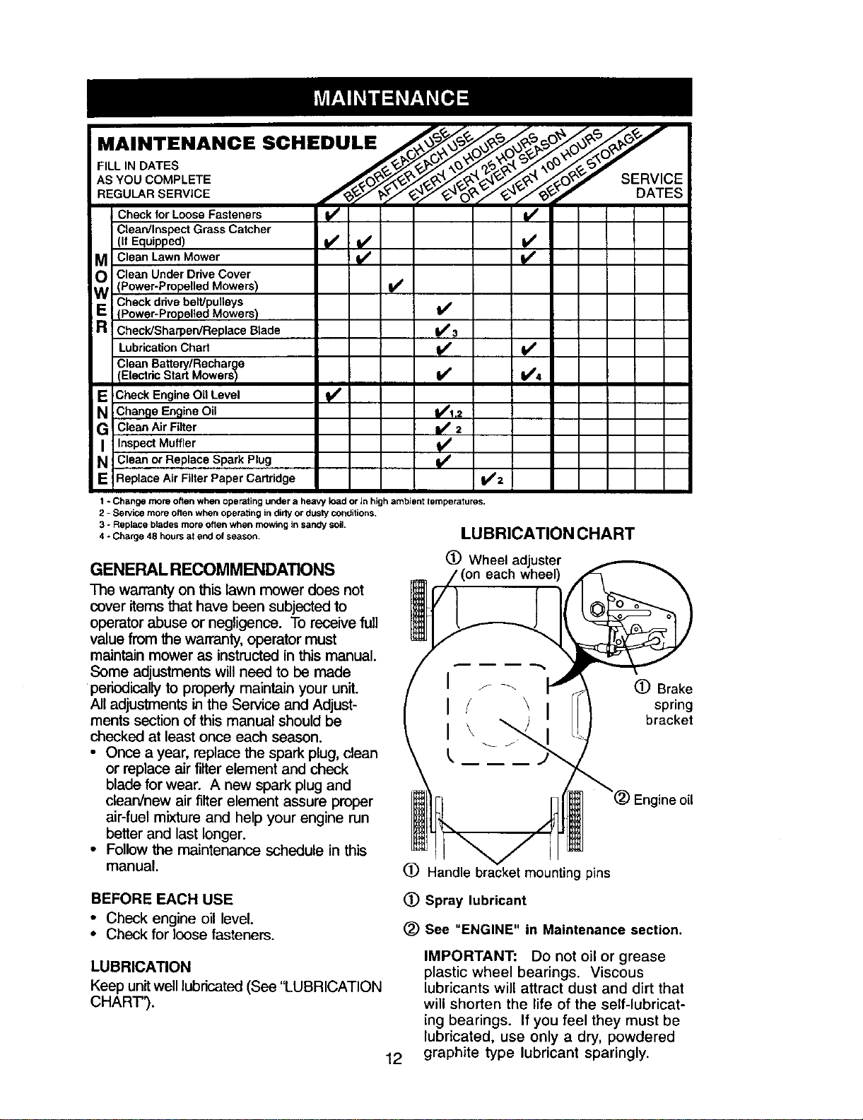
LUBRICATION CHART
(_) Wheel adjuster
each wheel)
(_) Brake
spring
bracket
oil
(_) Handle bracket mounting pins
BEFORE EACH USE
• Check engine oil level.
• Check for loose fasteners.
LUBRICATION
Keep unitwell lubricated (See "LUBRICATION
CHAR'F_.
12
(_) Spray lubricant
(_) See "ENGINE" in Maintenance section.
IMPORTANT: Do not oil or grease
plastic wheel bearings. Viscous
lubricants will attract dust and dirt that
will shorten the life of the self-lubricat-
ing bearings. If you feel they must be
lubricated, use only a dry, powdered
graphite type lubricant sparingly.
PRODUCT SPECIFICATIONS
Serial Number:
Date of Purchase:
Gasoline Capacity / Type: 1.5 Quarts (Unleaded Regular)
Oil Type (API-SF-SJ): SAE 30 (above 32°F); SAE 5W-30 (below 32°F)
Oil Capacity: 20 Ounces
Spark Plug (Gap: .045") Champion RN4C
Blade Bolt Torque: 35-40 ft. ibs.
• The model and serial numbers will be found on a decal on the rear of the mower
housing. Record both serial number and date of purchase in space provided above.
LAWN MOWER
Always observe safety rules when perform-
ing any maintenance.
TIRES
• Keep tires free of gasoline, oil, or insect
control chemicals which can harm rubber.
• Avoid stumps, stones, deep ruts, sharp
objects and other hazards that may cause
Ure damage.
BLADE CARE
For best results, mower blade must be
kept sharp. Replace bent or damaged
blades.
TO REMOVE BLADE
1. Disconnect spark plug wire from spark
plug and place wire where it cannot
come in contact with spark plug.
2. Turn lawn mower on its side. Make
sure air filter and carburetor are up.
3. Use a wood block between blade and
mower housing to prevent blade from
turning when removing blade bolt.
NOTE: Protect your hands with gloves
and/or wrap blade with heavy cloth.
4. Remove blade bolt by turning counter-
clockwise.
5. Remove blade and attaching hard-
ware (bolt, lock washer and hardened
washer).
NOTE: Remove the blade adapter and
check the key inside hub of blade
adapter. The key must be in good condi-
tion to work properly. Replace adapter if
damaged.
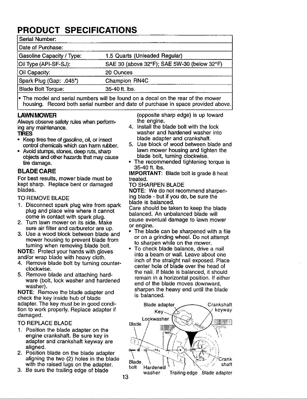
TO REPLACE BLADE
1. Position the blade adapter on the
engine crankshaft. Be sure key in
adapter and crankshaft keyway are
aligned.
2. Position blade on the blade adapter
aligning the two (2) holes in the blade
with the raised lugs on the adapter.
3. Be sure the trailing edge of blade
(opposite sharp edge) is up toward
the engine.
4. Install the blade bolt with the lock
washer and hardened washer into
blade adapter and crankshaft.
5. Use block of wood between blade and
lawn mower housing and tighten the
blade bolt, turning clockwise.
• The recommended tightening torque is
35-40 ft. Ibs.
IMPORTANT: Blade bolt is grade 8 heat
treated.
TO SHARPEN BLADE
NOTE: We do not recommend sharpen-
ing blade - but if you do, be sure the
blade is balanced.
Care should be taken to keep the blade
balanced. An unbalanced blade will
cause eventual damage to lawn mower
or engine.
• The blade can be sharpened with a file
or on a grinding wheel. Do not attempt
to sharpen while on the mower.
• To check blade balance, drive a nail
into a beam or wall. Leave about one
inch of the straight nail exposed. Place
center hole of blade over the head of
the nail. If blade is balanced, it should
remain in a horizontal position. If either
end of the blade moves downward,
sharpen the heavy end until the blade
is balanced.
Blade adaptel Crankshaft
Ke
Blade
Blade.
bolt
washer
13
_/_/ shaft
Trailing edge Blade adapter
ENGINE
LUBRICATION
Use only high quality detergent oil rated
with API service classification SF-SJ.
Select the oil's SAE viscosity grade
according to your expected operating
temperature.
SAE VISCOSITY GRADES
6O 8O
TEMPERATURE RANGE ANTICIPATED BEFORE .,_Xl"OIL CHANGE
NOTE: Although multi-viscosity oils
(5W30, 10W30 etc.) improve starting in
cold weather, these multi-viscosity oils
will result in increased oil consumption
when used above 32°F. Check your
engine oil level more frequently to avoid
possible engine damage from running
low on oil.
Change the oil after every 25 hours of
operation orat least once a year if the
lawn mower is not used for 25 hours in
one year.
Check the crankcase oil level before
starting the engine and after each five (5)
hours of continuous use. Tighten oil plug
securely each time you check the oil
level.
TO CHANGE ENGINE OIL
NOTE: Before tipping lawn mower to
drain oil, drain fuel tank by running
engine until fuel tank is empty.
1. Disconnect spark plug wire from spark
plug and place wire where it cannot
come in contact with spark plug.
2. Remove engine oil cap; lay aside on a
clean surface.
3. Tip lawn mower on its side as shown
and drain oil into a suitable container.
Rock lawn mower back and forth to
remove any oil trapped inside of
engine.
4. Wipe off any spilled oil from lawn
mower or side of engine.
5. Fill engine with oil. (See "ADD OIL" in
the Operation section of this manual).
6. Reconnect spark plug wire to spark
plug.
Container_
AIR FILTER
Your engine will not run properly and may
be damaged by using a dirty air filter,
Replace the air filter every 100 hours of
operation or every season, whichever
occurs first. Service air cleaner more
often under dusty conditions. Do not
wash air filter.
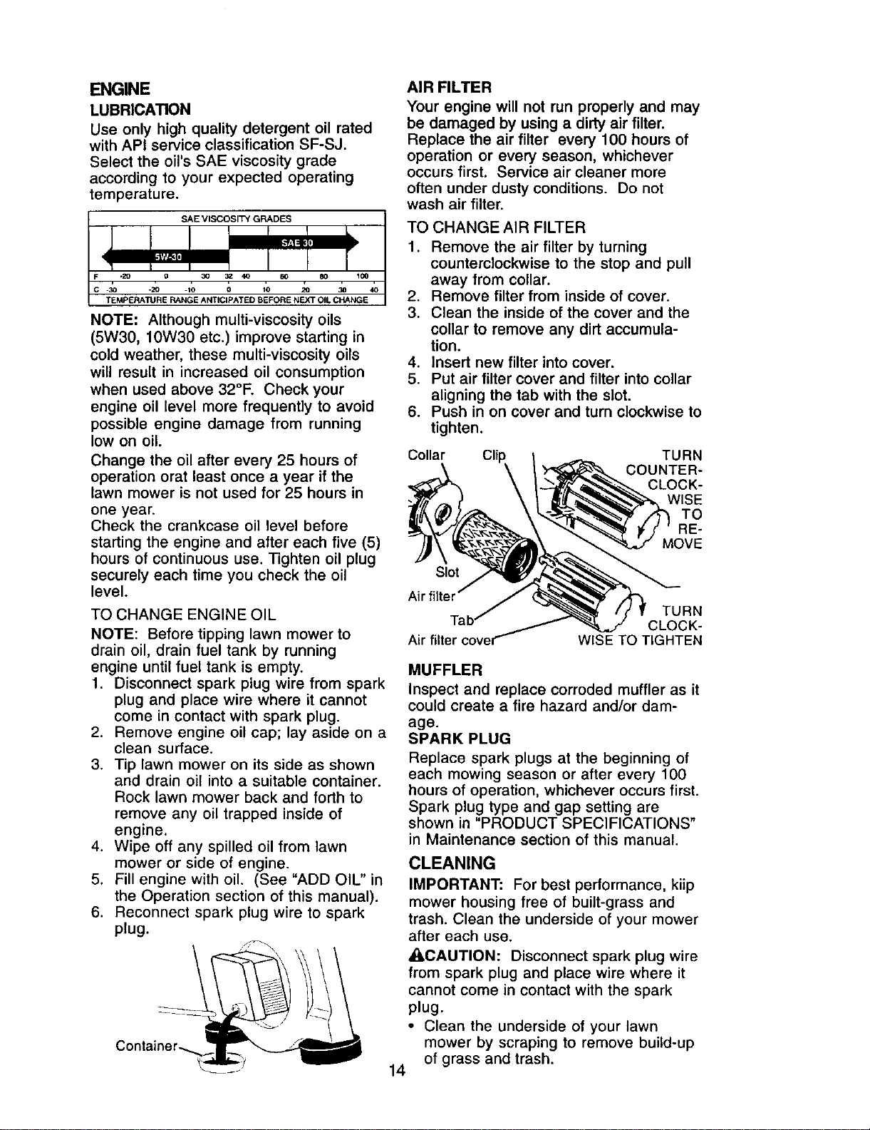
TO CHANGE AIR FILTER
1. Remove the air filter by turning
counterclockwise to the stop and pull
away from collar.
2. Remove filter from inside of cover.
3. Clean the inside of the cover and the
collar to remove any dirt accumula-
tion.
4. Insert new filter into cover.
5. Put air filter cover and filter into collar
aligning the tab with the slot.
6. Push in on cover and turn clockwise to
tighten.
Collar Cli TURN
COUNTER-
CLOCK-
WISE
TO
RE-
MOVE
Slot
Air filter
Air filter
TURN
CLOCK-
WlSETOTIGHTEN
MUFFLER
Inspect and replace corroded muffler as it
could create a fire hazard and/or dam-
age.
SPARK PLUG
Replace spark plugs at the beginning of
each mowing season or after every 100
hours of operation, whichever occurs first.
Spark plug type and gap setting are
shown in "PRODUCT SPECIFICATIONS"
in Maintenance section of this manual.
CLEANING
IMPORTANT: For best performance, kiip
mower housing free of built-grass and
trash. Clean the underside of your mower
after each use.
_CAUTION: Disconnect spark plug wire
from spark plug and place wire where it
cannot come in contact with the spark
plug.
• Clean the underside of your lawn
mower by scraping to remove build-up
of grass and trash.
14
• Clean engine often to keep trash from
accumulating. A clogged engine runs
hotter and shortens engine life.
• Keep finished surfaces and wheels free
of all gasoline, oil, etc.
• We do not recommend using a garden
hose to clean lawn mower unless the
electrical system, muffler, air filter and
carburetor are covered to keep water
out. Water in engine can result in
shortened engine life.
_I_WARNING: To avoid serious injury,
before performing any service or adjust-
meats:
1. Release control bar and stop engine.
2. Make sure the blade and all moving
parts have completely stopped.
3. Disconnect spark plug wire from spark
plug and place where it cannot come
in contact with plug.
LAWN MOWER
TO ADJUST CUTTING HEIGHT
See "TO ADJUST CUTTING HEIGHT" in
the Operation section of this manual.
REAR DEFLECTOR
The rear deflector, attached between the
rear wheels of your mower, is provided to
minimize the possibility that objects will
be thrown out of the rear of the mower into
the operator's mowing position. If the
deflector becomes damaged, it should be
replaced.
DISCHARGE GUARD
The discharge guard, attached to the
discharge opening of your lawn mower, is
provided to prevent the possibility of injury
resulting from bbjects being thrown out of
the discharge opening into the operator
mowing position. If the discharge guard
becomes damaged, it should be replaced.
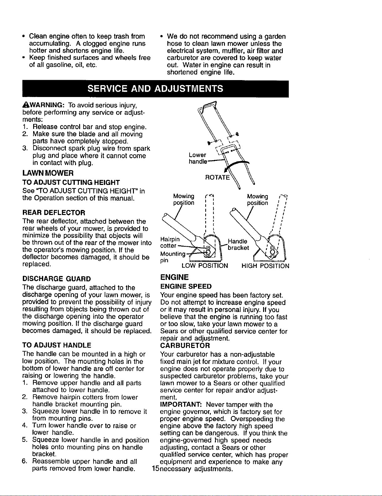
TO ADJUST HANDLE
The handle can be mounted in a high or
low position. The mounting holes in the
bottom of lower handle are off center for
raising or lowering the handle.
1. Remove upper handle and all parts
attached to lower handle.
2. Remove hairpin cotters from lower
handle bracket mounting pin.
3. Squeeze lower handle in to remove it
from mounting pins.
4. Turn lower handle over to raise or
lower handle.
5. Squeeze lower handle in and position
holes onto mounting pins on handle
bracket.
6. Reassemble upper handle and all
parts removed from lower handle.
Lower "_'_
handle-'--'-"
ROTATE
Mowing
position
Hairpin
Mounting-_
pin
LOW POSITION
ENGINE
ENGINE SPEED
Your engine speed has been factory set.
Do not attempt to increase engine speed
or it may result in personal injury. If you
believe that the engine is running too fast
or too slow, take your lawn mower to a
Sears or other qualified service center for
repair and adjustment.
CARBURETOR
Your carburetor has a non-adjustable
fixed main jet for mixture control. If your
engine does not operate properly due to
suspected carburetor problems, take your
lawn mower to a Sears or other qualified
service center for repair and/or adjust-
ment.
IMPORTANT: Never tamper with the
engine governor, which is factory set for
proper engine speed. Overspeeding the
engine above the factory high speed
setting can be dangerous. If you think the
engine-governed high speed needs
adjusting, contact a Sears or other
qualifred service center, which has proper
equipment and experience to make any
15necessary adjustments.
Immediately prepare your lawn mower for
storage at the end of the season or if the
unit will not be used for 30 days or more.
LAWN MOWER
When lawn mower is to be stored for a
period of time. clean it thoroughly, remove
all dirt, grease, leaves, etc. Store in a
clean, dry area.
1. Clean entire lawn mower (See
"CLEANING" in the Maintenance
section of this manual).
2. Lubricate as shown in the Mainte-
nance section of this manual.
3. Be sure that all nuts, bolts, screws,
and pins are securely fastened.
Inspect moving parts for damage,
breakage and wear. Replace if
necessary.
4. Touch up all rusted or chipped paint
surfaces; sand lightly before painting.
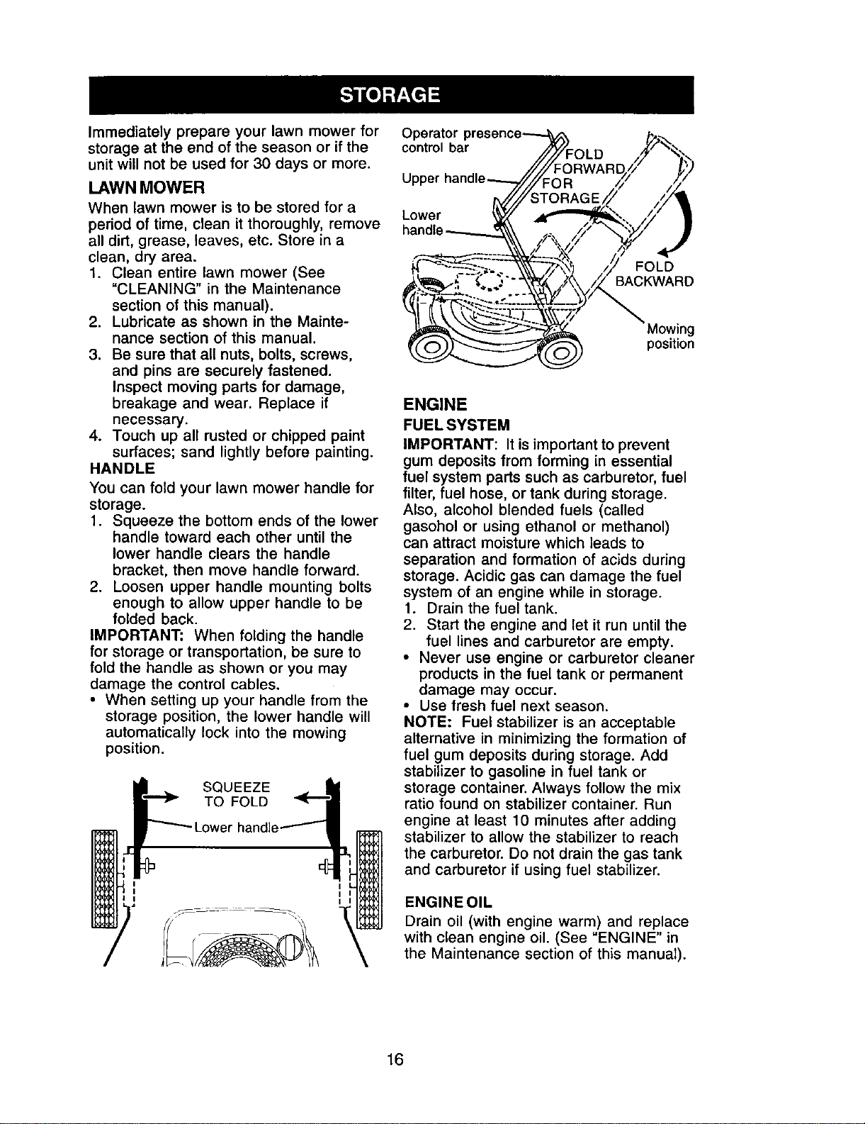
HANDLE
You can fold your lawn mower handle for
storage.
1. Squeeze the bottom ends of the lower
handle toward each other until the
lower handle clears the handle
bracket, then move handle forward.
2. Loosen upper handle mounting bolts
enough to allow upper handle to be
folded back.
IMPORTANT: When folding the handle
for storage or transportation, be sure to
fold the handle as shown or you may
damage the control cables.
• When setting up your handle from the
storage position, the lower handle will
automatically lock into the mowing
position.
SQUEEZE
TO FOLD
control bar
Upper
Lower
FOLD
BACKWARD
,g
position
ENGINE
FUEL SYSTEM
IMPORTANT: It is important to prevent
gum deposits from forming in essential
fuel system parts such as carburetor, fuel
filter, fuel hose, or tank during storage.
Also, alcohol blended fuels (called
gasohol or using ethanol or methanol)
can attract moisture which leads to
separation and formation of acids during
storage. Acidic gas can damage the fuel
system of an engine while in storage.
1. Drain the fuel tank.
2. Start the engine and let it run until the
fuel lines and carburetor are empty.
• Never use engine or carburetor cleaner
products in the fuel tank or permanent
damage may occur.
• Use fresh fuel next season.
NOTE: Fuel stabilizer is an acceptable
alternative in minimizing the formation of
fuel gum deposits during storage. Add
stabilizer to gasoline in fuel tank or
storage container. Always follow the mix
ratio found on stabilizer container. Run
engine at least 10 minutes after adding
stabilizer to allow the stabilizer to reach
the carburetor. Do not drain the gas tank
and carburetor if using fuel stabilizer.
ENGINEOIL
Drain oil (with engine warm) and replace
with clean engine oil. (See "ENGINE" in
the Maintenance section of this manual).
16
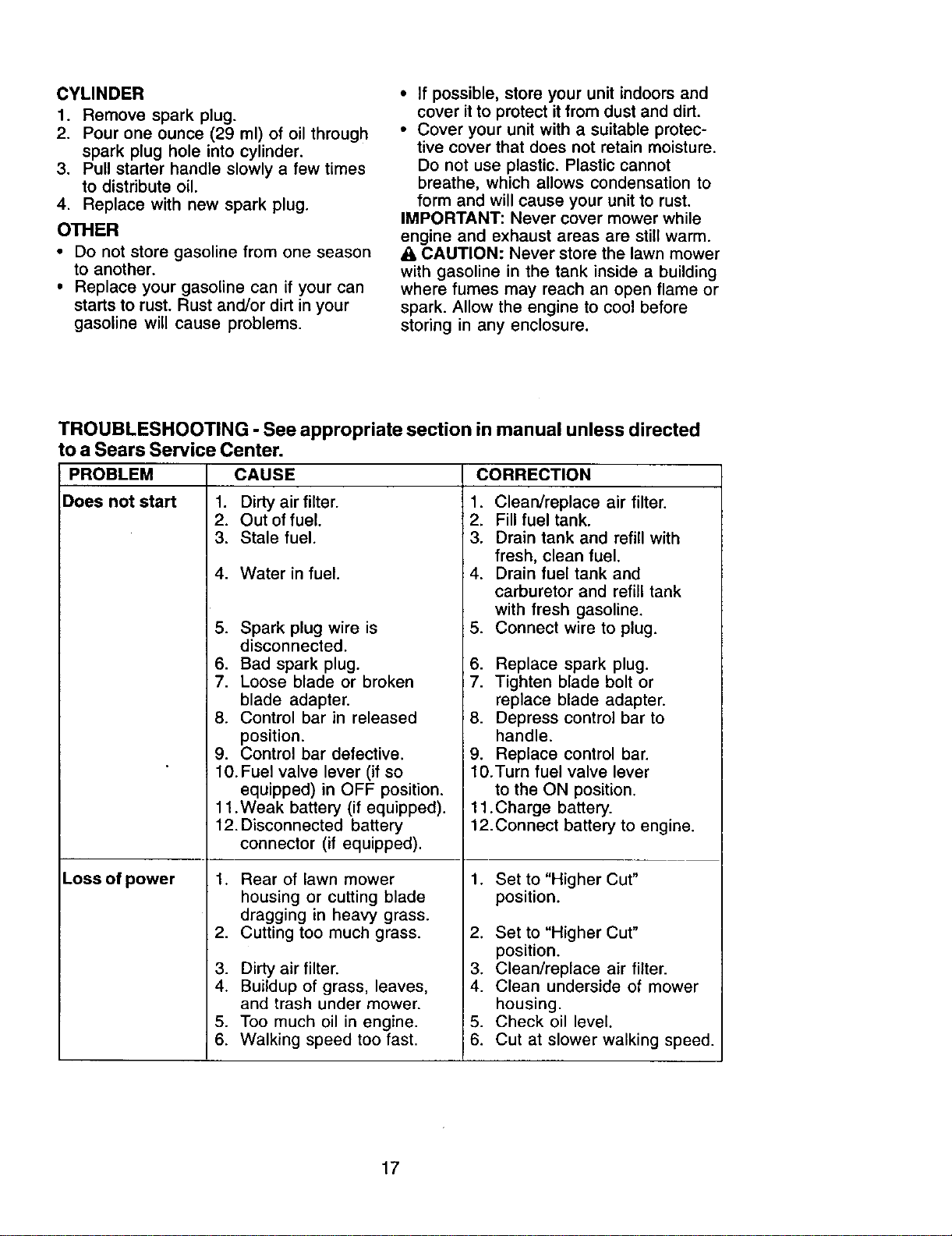
CYLINDER
1. Remove spark plug.
2. Pour one ounce (29 ml) of oil through
spark plug hole into cylinder.
3. Pull starter handle slowly a few times
to distribute oil.
4. Replace with new spark plug.
OTHER
• Do not store gasoline from one season
to another.
• Replace your gasoline can if your can
starts to rust. Rust and/or dirt in your
gasoline will cause problems.
• If possible, store your unit indoors and
cover it to protect it from dust and dirt.
• Cover your unit with a suitable protec-
tive cover that does not retain moisture.
Do not use plastic. Plastic cannot
breathe, which allows condensation to
form and will cause your unit to rust.
IMPORTANT: Never cover mower while
engine and exhaust areas are still warm.
A CAUTION: Never store the lawn mower
with gasoline in the tank inside a building
where fumes may reach an open flame or
spark. Allow the engine to cool before
storing in any enclosure.
TROUBLESHOOTING - See appropriate section in manual unless directed
to a Sears Service Center.
PROBLEM CAUSE CORRECTION
Does not start 1. Dirty air filter. 1. Clean/replace air filter.
Loss of power
2. Out of fuel.
3. Stale fuel.
4. Water in fuel.
5. Spark plug wire is
disconnected.
6. Bad spark plug.
7. Loose blade or broken
blade adapter.
8. Control bar in released
position.
2. Fill fuel tank.
3. Drain tank and refill with
fresh, clean fuel.
4. Drain fuel tank and
carburetor and refill tank
with fresh gasoline.
5. Connect wire to plug.
6. Replace spark plug.
7. Tighten blade bolt or
replace blade adapter.
8. Depress control bar to
handle.
9. Control bar defective.
10.Fuel valve lever (if so
equipped) in OFF position.
11 .Weak battery (if equipped).
12. Disconnected battery
connector (if equipped).
.
.
3.
4.
5.
6.
Rear of lawn mower
housing or cutting blade
dragging in heavy grass.
Cutting too much grass.
Dirty air filter.
Buildup of grass, leaves,
and trash under mower.
Too much oil in engine.
Walking speed too fast.
9. Replace control bar.
10.Turn fuel valve lever
to the ON position.
11 .Charge battery.
12. Connect battery to engine.
1. Set to "Higher Cut"
position.
2. Set to "Higher Cut"
position.
3. Clean/replace air filter.
4. Clean underside of mower
housing.
5. Check oil level.
6. Cut at slower walking speed.
17
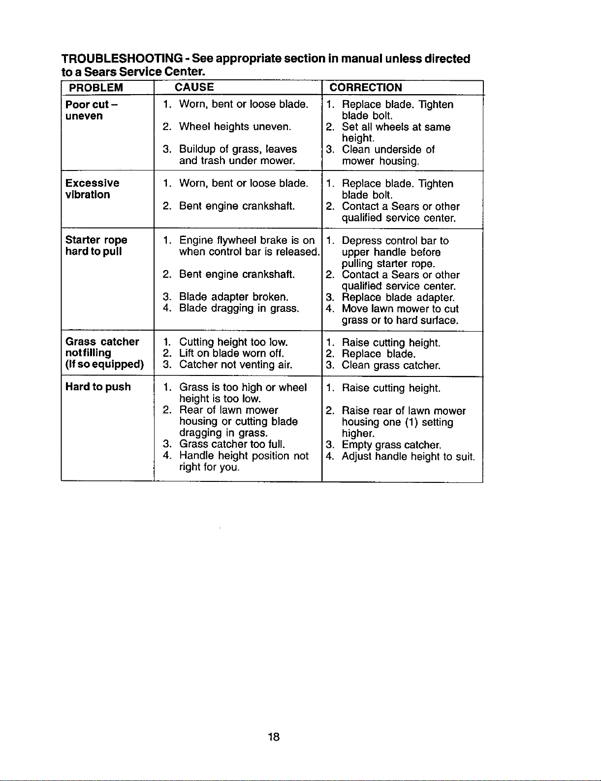
TROUBLESHOOTING - See appropriate section in manual unless directed
to a Sears Service Center.
PROBLEM CAUSE CORRECTION
Poor cut- 1. Worn, bent or loose blade. 1. Replace blade. "l]ghten
uneven blade bolt.
2. Wheel heights uneven. 2. Set all wheels at same
height.
3. Buildup of grass, leaves 3. Clean underside of
and trash under mower, mower housing.
Excessive 1. Worn, bent or loose blade. 1. Replace blade. _ghten
vibration blade bolt.
2. Bent engine crankshaft. 2. Contact a Sears or other
qualified service center.
Starter rope Engine flywheel brake is on
hard to pull when control bar is released.
.
2.
3.
4.
Bent engine crankshaft.
Blade adapter broken.
Blade dragging in grass.
1. Depress control bar to
upper handle before
pulling starter rope.
2. Contact a Sears or other
qualified service center.
3. Replace blade adapter.
4. Move lawn mower to cut
grass or to hard surface.
Grass catcher 1. Cutting height too low. 1. Raise cutting height.
notfilling 2. Lift on blade worn off. 2. Replace blade.
(Ifsoequipped) 3. Catcher not venting air. 3. Clean grass catcher.
Hard to push 1. Raise cutting height.
1. Grass is too high or wheel
height is too low.
2. Rear of lawn mower
housing or cutting blade
dragging in grass.
3. Grass catcher too full.
4. Handle height position not
right for you.
2. Raise rear of lawn mower
housing one (1) setting
higher.
3. Empty grass catcher.
4. Adjust handle height to suit.
18
Garanfia ........................................................ 19
Reglas de Seguridad ............................... 19-21
Montaje / Operaci6n ................................ 23-25
Operaci6n ................................................ 26-28
Mantenimiento ......................................... 29-32
Programa de Mantenimiento ......................... 29
Especificaoiones del Producto ..................... 30
Servicio y Adjustes ....................................... 32
Almacenamiento ...................................... 33-34
Identificaci6n de problemas .................... 34-35
PaRes de repuesto ................................. 36-41
Servicio Sears ................................ Contratapa
GARANTiA LIMITADA DE DOS AI_IOSPARA LA SEGADORA A MOTOR CRAFTSMAN
Por uno (1) afio, a partir de la fecha de compra, cuando esta Segadora Craftsman se mantenga, lubrique
y afine seg,',nlas instrucciones para la operaci6n y el mantenimiento en el manual del duefio, Sears
reparard gratis todo defecto en el material y la mano de obra.
Si la Segadora Craftsman se usa para fines comerciales o de arriendo, esta garantfa s01ose aplica por
noventa (90) dfas a parlir de la fecha de compra.
Esta Garantia no cubre:
• Articulos que se desgastan durante el eso normal tales como las cuchilles segadoras rotatories, los
adaptadores de la cuchilla,les correes, los filtres de aire y las bujfas.
• Reparacionesnecesarias debido al abuso o a la negligencia del operador, incluy_ndese a los
cigLiefialesdeblados y a la falta de mantenimiento del equipo seg0n las instrueslones que se incluyen
an el manualdel duefio.
EL SERVlCIO DE GARANTiA ESTADISPONIBLE al devolver la segadera a motor Craftsman al Centro/
Departmento de Servicio Sears mas cercano en los Estados Unidos. Esta garantia se aplica solamente
mientras el producto este en uso en los Estades Unides.
Esta Garantfa le otorga derechos legales especificos, y puede que tambien tenga otros derechos que
varian de estade a estado.
Sears, Roebuck and Co., D/817WA, Hoffman Estates, IL 60179 USA
IMPORTANTE: Esta maquina cortadaora es capaz de amputar las manos y los manos y los
pies y de lanzar objetos. Si no se observan las instrucciones de seguridad siguientes se pueden
producir lesiones graves o la muerte.
_Busque este simbolo que sefiala las
precauciones de segaridad, de importancia.
Quiere decir- iiiATENCION!!!iiiESTE
ALERTOI!! SU SEGURIDAD ESTA
COMPROMETIDA.
_I,ADVERTENClA: Siempre desconecte el
alambre de la bujia y pbngalo donde no pueda
entrar en contacto con la bujia, para evitar el
arranque pot accidente, durante la
preparaci6n, el transporte, el ajuste o cuando
se hacen reparaciones.
_I_DVERTENClA: Los bornes, terminales y
accesorios relativos de la bateria contienen
plomo o compuestos de plomo, productos
quimicos conocidos en el Estado de California
como causa de cancer y defectos al
nacimianto u otros dafios reproductivos. Lavar
las manos despu_s de manipularlos.
,APRECAUCION: El tubo de escape del
motor, algunos de sus constituyentesy
algunos componentes del vehiculo contienen
o desprenden productos quimicos conocidos
en el Estado de California como causa de
cdncer y defectos al nacimiento u otres dafios
reproductivos.
_kPRECAUCI6N: El silenciador y otras
piezas del motor tlegan a sre extremademente
calientes durante la operaci6n y siguen siendo
calientes despu_s de que el motor haya
parade. Para evitar quemaduras severas,
permanezca lejos de estas dreas.
19
I. OPERACION
• Antes de empezar, debe familiadzarse
completamente con los controles y el uso
correcto de la maquina. Para esto, debe leer
y comprender todas las instrucciones que
aparecen en la maquina yen los manuales
de operaci6n.
• No ponga las manos o los pies cerca o
debajo de las partes rotatorias. Mant6ngase
siempre lejos de la abertura de la descarga.
• Permita que solamente las personas
responsables que estdn familiarizadas con
las instruccionesoperen la mdquina.
• Despeje el _rea de objetos tales como
piedras, juguetes, alambres, huesos, palos,
etc. que pueclen ser recogidos y lanzados
por las cuchillas.
• Aseg_rese que el _rea no se hallen
personas, antes de segar. Pare la m&quina
si alguien entra en el ._rea.
• No opere la maquina sin zapatos o con
sandalias abiertas. P6ngase siempre
zapatos s61idos.
• No tire de la segadora hacia atr&s a menos
que sea absolutamente necesario. Mire
siempre hacia abajo y hacia detr&s antes y
mientras que se mueve hacia atr&s.
• No opere la segadora sin los respectivos
resguardos, las placas, el recogedor de
c_sped u otros aditamentos dise ados para
su protecci6n y seguridad.
• Refi_rase alas instrucciones del fabricante
para el funcionamiento e instalaci6n de
accesorios. NO utilizar accesorios no
recomendados por el constructor de la
segadora, como dispositivos anti-paja de la
hoja, que pueden ser peligrosos y dafiar la
segadora.
• Detenga la cuchilla o las cuchillas cuando
cruce por calzadas, calles o caminos de
grava.
• Parar el motor cada vez que se abandona
el aparato, antes de limpiar la segadora o de
remover residuos del tubo.
• Apagar el motor y esperar hasta que las
cuchillas esten completamente paradas
antes de remover el receptor de hierba.
• Segar solamente con luz del dfa o con una
buena luz artificial.
• No opere la m&quina bajo la influencia del
alcohol o de las drogas.
• Nunca opere la maquina cuando la hierba
est_ mojada. Asegt_rese siempre de tener
buena tracci6n en sus pies; mantenga el
mango firmemente y camine; nunca corra.
• Desconectar el mecanismo de propulsi6n
aut6noma o el embrague de transmisi6n en
las segadoras que Io tienen antes de porter
en marcha el motor.
• Si el equipo empezara a vibrar de una
manera anormal, pare el motor y revise de
inmediato para averiguar la causa.
Generalmente la vibracibn suele indicar que
existe alguna averfa.
• Siempre use galas de seguridad o anteojos
con protecci6n lateral cuando opere la
segadora.
II. OPERACION SOBRE LAS CUESTAS
Los accidentes ocurren con m&s frecuencia
en las cuestas. Estos accidentes ocurren
debido a resbaladas o ca_das, las cuales
pueden resultar en graves lesiones. Operar la
recortadora en cuestas requiere mayor
concentraci6n. Si se siente inseguro en una
cuesta, no la recorte.
HACER"
• Puede recortar a trav_s de la superficie de
la cuesta, nunca hacia arriba y hacia abajo.
Proceda con extrema precauci6n cuando
cambie de direcci6n en las cuestas.
• Renueva todos los objetos extrafios, tales
como guijarros, ramas, etc.
• Debe prestar atenci6n a hoyos, baches o
protuberancias. Recuerde que la hierba alta
puede esconder obst_.culos.
NO HACER:
• No recorte cerca de pendientes, zanjas o
terraplenes. El operador puede perder la
tracci6n en los pies o el equilibrio.
• No recorte cuestas demasiado inclinadas.
• No recorte en hierba mojada. La reducci6n
en la tracci6n de la pisada puede causar
resbalones.
II1.NII_IOS
Se pueden produciraccidentes tr&gicossi el
operador no presta atenci6n a la presencia de
los nifios. A menudo, los nihos se sienten
atrafdos por la m._quinay por la actividad de la
siega. Nunca suponga que los nifios van a
permanecer en el mismo lugar donde los vio
por t_ltimavez.
• Mantenga a los nifios alejados del &rea de la
siega y bajo el cuidado estricto de otra
persona adulta responsable.
• Est_ alerta y apague la m._quinasi hay
nifios que entran al &rea.
• Antes y cuando este retrocediendo, mire
hacia atr&s y hacia abajo para verificar si
hay nifios pequefios.
• Nunca permita que los nifios operen la
m&quina.
• Teoga un cuidado extra cuando se acerque
a esquinas donde no hay visibilidad, a los
arbustos, &rboles u otros objetos que
pueden interferir con su Ifnea de visi6n.
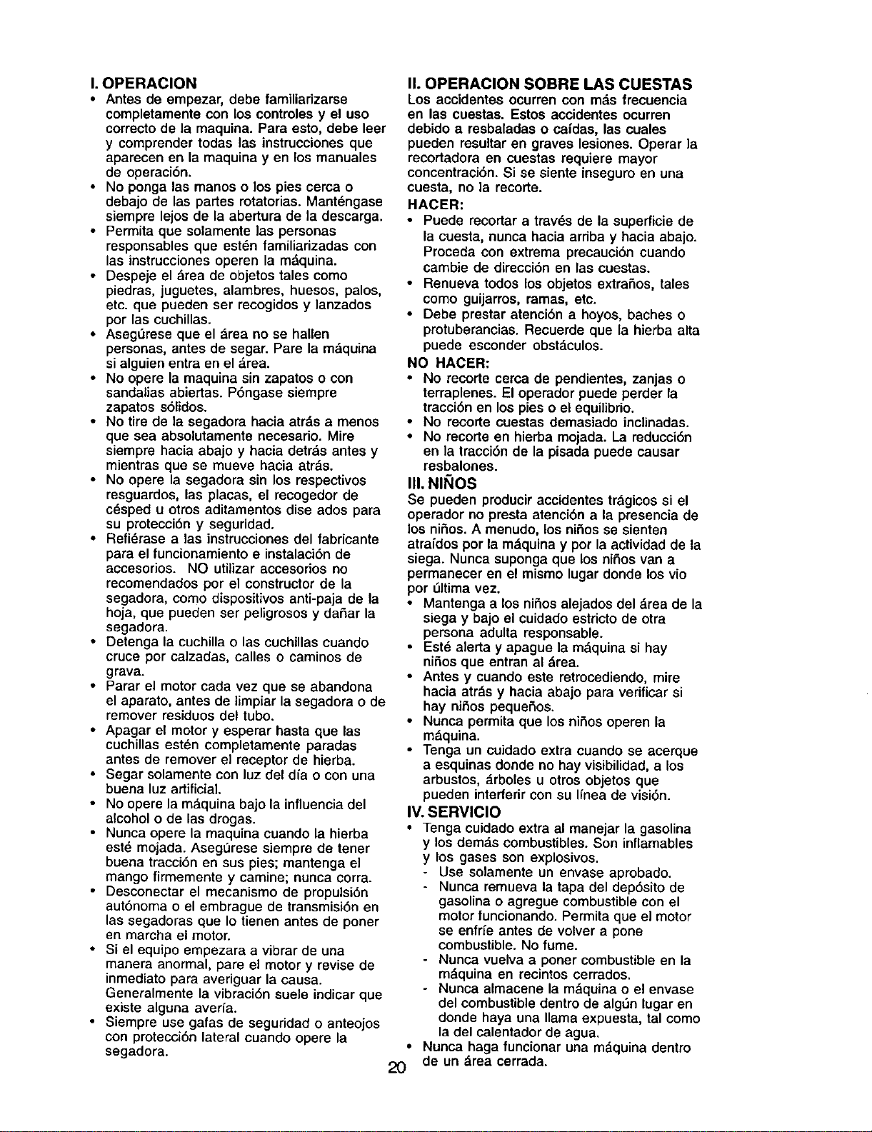
IV. SERMICIO
• Tenga cuidado extra al manejar la gasolina
y los dem_.s combustibles. Son inflamables
y los gases son explosivos.
- Use solamente un envase aprobado.
- Nunca remueva la tapa del dep6sito de
gasolina o agregue combustible con el
motor funcionando. Permita que el motor
se enfrfe antes de volver a pone
combustible. No fume.
- Nunca vuelva a porter combustible en la
m&quina en recintos cerrados.
- Nunca almacene la m&quina o el envase
del combustible dentro de algSn lugar en
donde haya una llama expuesta, tal como
la del calentador de agua.
• Nunca haga funcionar una m._quina dentro
20 de un (lrea cerrada.
• Nunca haga ajustes o reparaciones
mientras el motor estd en marcha.
Desconecte el cable de la buj{a, y
mantdngalo a cierta distancia de 6sta para
prevenir un arranque accidental.
• Mantenga Ins tuercas y los pemos,
especialmente los pernos del accesorio de
la cuchilla, apretados y mantenga el equipo
en buenas condiciones.
• Nunca manipule de forma indebida los
dispositivos de seguridad. Controle
regularmente su funcionamiento correcto.
• Mantenga la m_quina libre de hierba, hojas
u otras acumulaciones de desperdicio.
Limpie los derrames de aceite o combus-
tible. Permita que la m&quina se enfrfe antes
de almacenarla.
• Pare e inspeccione el equipo si le pega aun
objeto. Reparelo, si es necesario, antes de
hacerlo arrancar.
• En ningdn caso hay que regular la altura de
Ins ruedas mientras el motor estd en
marcha.
• Los componentes del receptor de la hierba
van sujetos a desgaste, da£zosy deteriore,
que pueden exponer Ins panes en
movimiento o permitir que objetos scan
disparedos. Contmlar frecuentemente y
cuando sea necesado sustituir con partes
aconsejadas por el fabricante.
• Las cuchinas de la segadora estdn afiladas
y pueden cortar. Cubdr Ins hojas o Ilevar
guantes, y utUizar precauciones especiales
cuando se efectda mantenimiento sobre Ins
mismas.
• No cambie el ajuste del regolador del motor
ni exceda su velocidad.
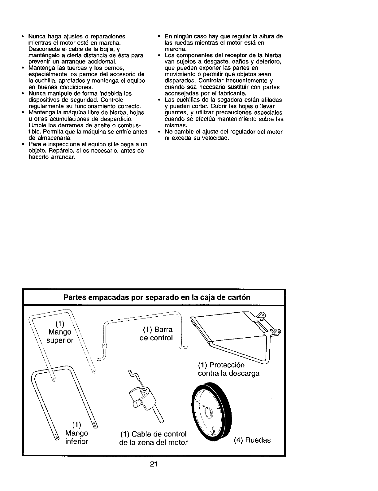
Partes empacadas por separado en la caja de cartbn
I
Mangc
superior
(1)
Mango
inferior
(1) Barra /
/o/ decontrol /j_
'\\ _S/
(1) Cable de control
de la zona del motor
(1) Protecci6n
contra la descarga
(4) Ruedas
21
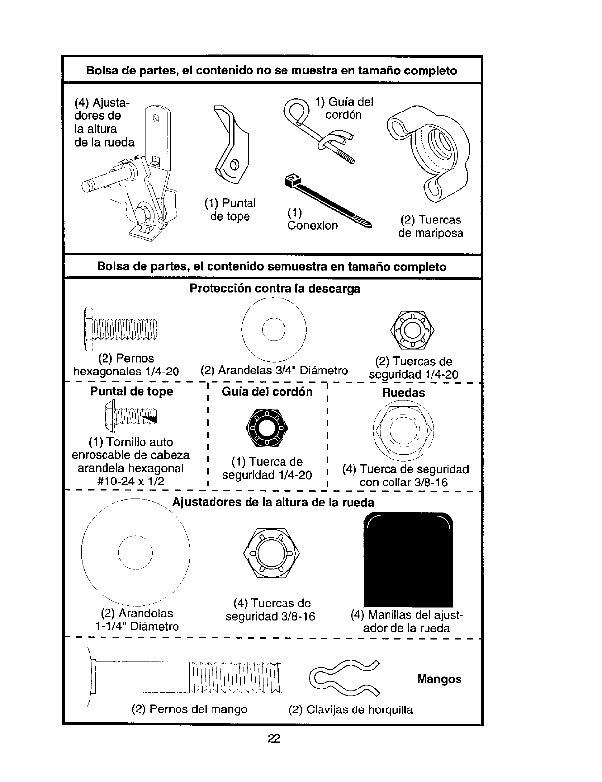
Bolsa de partes, el contenido no se muestra en tamaSo completo
(4) Ajusta-
dores de
la altura
de la rueda
(1) Puntal
de tope
(2) Tuercas
de mariposa
Bolsa de partes, el contenido semuestra en tama_o completo
Proteccibn contra la descarga
(2) Pernos
\
@
(2) Tuercas de
hexagonales 1/4-20
Puntal de tope
(1) Tornillo auto
enroscable de cabeza
arandela hexagonal
#10-24 x 1/2
(2) Arandelas 3/4" DiCJmetro
-n Guia del cord6n -I
(1) Tuerca de
seguridad 1/4-20
seguridad 1/4-20
Ruedas
(4) Tuerca de seguridad
con collar 3/8-16
j_ Ajustadores de la altura de la rueda
/
(2) Arandelas
1-1/4" Diametro
(4) Tuercas de
seguridad 3/8-16
(4) Manillas del ajust-
ador de la rueda
(2) Pernos del mango
(__ Mangos
(2) Clavijas de horquilla
22
_I_,PRECAUCl6N: No haga funcionar su
segadora sin el desviador de recortes o sin el
recogedor de c_sped, aprobados, en su lugar.
Estos dispositivos de seguridad son para su
protecci6n y son requeridos pot el American
National Standards Institutey el U.S. Con-
sumer Product Safety Commission.
_I_PRECAUCI(_N: Desconecte el cable de
bujfa de la bujfa y p6ngalo donde no pueda
ponerce en contacto con la bujfa.
Lea estas instruccionesy este manual
completamente antes de tratar de montar u
operar su segadora nueva.
IMPORTANTE: Este cortacesped viene SIN
ACEITE O GASOLINA en el motor.
Su segadora nueva ha sido montada en la
f_.brica con la excepci6n de aquellas partes
que se dejaron sin montar por razonee de
envio. Todas las panes como las tuercas, las
arandelas, los pemos, etc., que son
necesarias para completar el montaje hart sido
colocadas en la bolsa de panes. Para
asegurarse que su segadora funcione en
forma segura y adecuada, todas las partes y
los artfculos de ferreterfa que se monten
tienen que ser apretados seguramente. Use
las herramientas correctas, como sea
necesario, para asegurar que se aprieten
adecuadamente.
HERRAMIENTAS NECESARIAS PARA
EL MONTAJE
Un juego de lave de tubo hard el ensamble
m_.s fdcil. Medidas estandartes estdn listadas.
(1) Llave de (1) Llave de tubo
tubode 5/16" de ajuste
(f) Llave de (1) Llave de tubo
tubode 1/2_ de 3/4"
(1) Llave de tubo (1) Llave de tubo
de 7/16" de 9/16"
Cuando la mano derecha o la mano izquierda
estdn mencionadas en este manual, significa
que usted esta situado en la posici6n de
operador detras del mango.
DESEMPAQUETE EL CARTON
1. Remueva todas las panes sueltas de la
caja de cart6n.
2. Examine todos los aniculos. Compdrelos
con la lista de panes no montadas y de los
articulos de ferreterfa.
3. Remueva la caja de la segadora con
cuidado. Evitetocar la cuchilladebajo de la
caja. Siempre use guantes y otras
protecciones cuando trabaje debajo de la
segadora o cuando la levante.
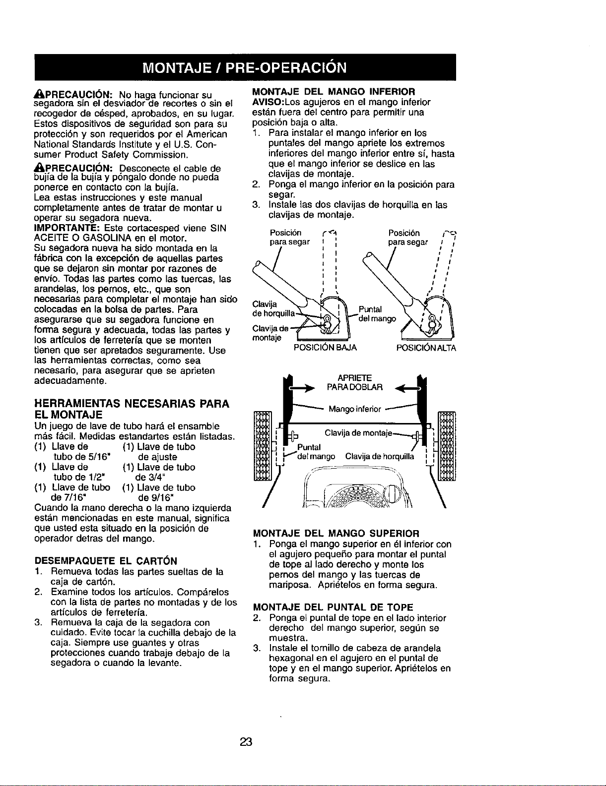
MONTAJE DEL MANGO INFERIOR
AVISO:Los agujeros en el mango inferior
estdn fuera del centro para permitiruna
posici6n baja o alta.
1. Para instalar el mango inferioren los
puntales del mango apriete los extremes
inferiores del mango inferior entre si, hasta
que el mango inferiorse deslice en las
clavijas de montaje.
2. Ponga el mango inferior en la posicionpara
segar.
3. Instale las dos clavijas de horquillaen las
clavijas de montaje.
Posici6n
parasegar
Clav_a
Clavija de-
montaje
POSIClON BAJA
f_'_ Posicibn i_
I parasegar /
, /
1
POSICl6N ALTA
APRIETE I
PARADOBLAR
Mangoinfedor --_
Clavija de montaje-_
Clavijadehorquilla [ I
MONTAJE DEL MANGO SUPERIOR
1. Ponga el mango superior en 51inferiorcon
el agujero pequeSo para montarel puntal
de tope al lado derecho y monte los
pernos del mango y las tuercas de
mariposa. Aprietelos en torma segura.
MONTAJE DEL PUNTAL DE TOPE
2. Ponga el puntal de tope en el lado interior
derecho del mango superior,seg6n se
muestra.
3. Instale el tornillode cabeza de arandela
hexagonal en el agujero en el puntal de
tope yen el mango superior. Apri_telos en
forma segura.
23
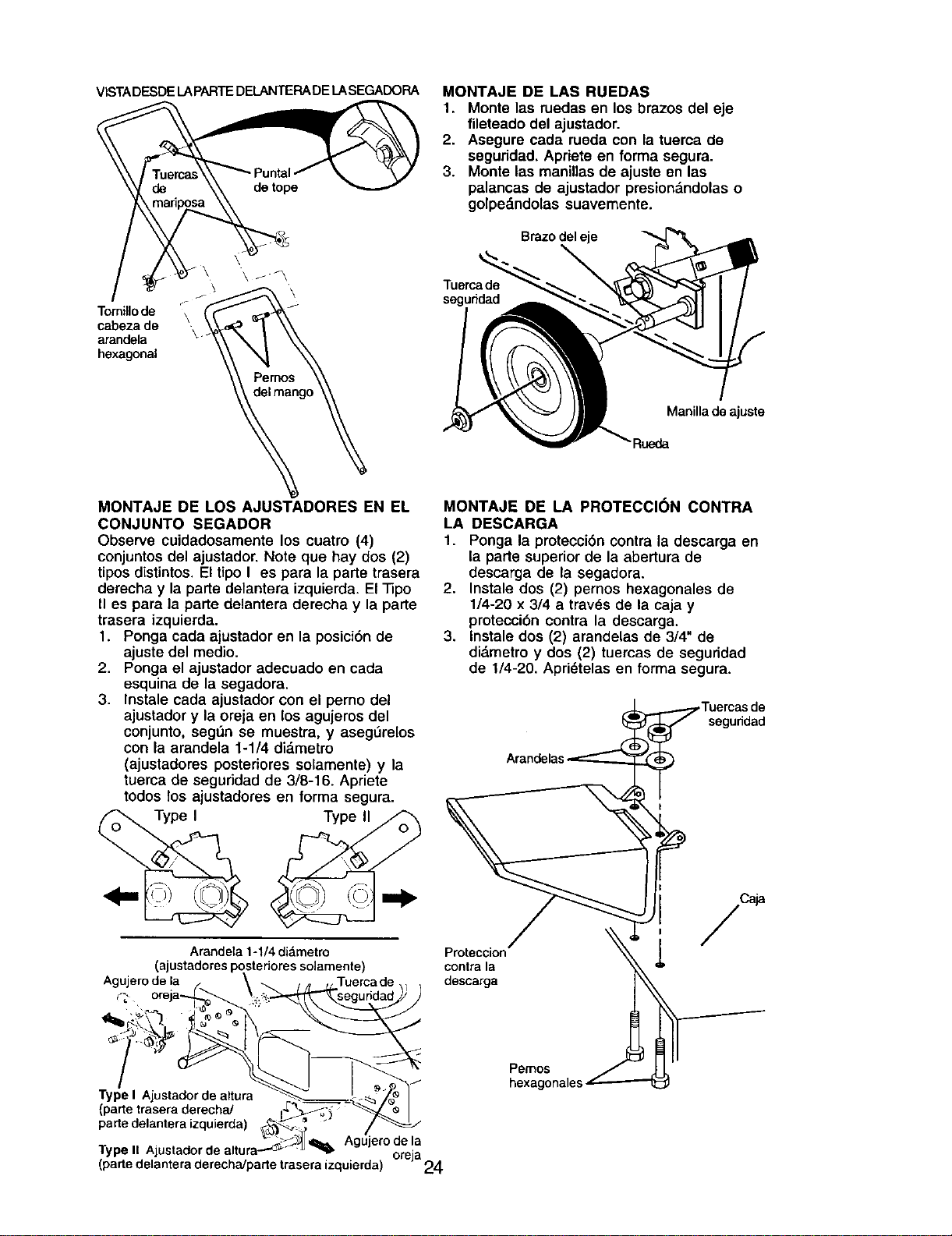
VISTADESDELAPARTEDELANTERADELASEGADORA
\
Tomillo de
cabeza de
arandela
hexagonal
MONTAJE DE LAS RUEDAS
1. Monte las ruedas en los brazes del eje
fileteado del ajustader.
2. Asegure carla rueda con la tuerca de
seguridad. Apriete en forma segura.
3. Monte las manillas de ajuste en las
palancas de ajustador presiondndolas o
golpe_ndolas suavemente.
Braze deleje
Tuerca de
seguddad
Manillade ajuste
Rueda
MONTAJE DE LOS AJUSTADORES EN EL
CONJUNTO SEGADOR
Observe cuidadosamente los cuatro (4)
conjuntosdel ajustador. Note que hay dos (2)
tipos distintos. El tipo I es para la parte trasera
derecha y la parte delantera izquierda. El "13po
II es para la parte delantera derecha y la parte
trasera izquierda.
1. Ponga carla ajustador en la posici6n de
ajuste del medio.
2. Ponga el ajustador adecuado en cacla
esquina de la segadora.
3. Instale cada ajustador con el perno del
ajustador y la oreja en los agujeros del
conjunto, segt_n se muestra, y asegOrelos
con la arandela 1-1/4 didmetro
(ajustadores posteriores solamente) y la
tuerca de seguridad de 3/8-16. Apriete
todos los ajustadores en forma segura.
Type II
Arandela 1-1/4 didmetro
(ajustadores postedores solamente)
Agujero de la Tuerca de
Type I Ajustador de altura
(parte trasera derecha/
parte delantera izquierda) _---_
_._-_'_ Agujero de la
Type II Ajustador de altura -'-''_ "_
(parte delantera derecha/parte trasera izquierda) °reja 24
MONTAJE DE LA PROTECCI(_N CONTRA
LA DESCARGA
1. Ponga la protecci6n contra la descarga en
la parte superior de la abertura de
descarga de la segadora,
2. Instale dos (2) pernos hexagonales de
1/4-20 x 3/4 a travds de la caja y
protecci6n contra la descarga.
3. Instale dos (2) arandelas de 3/4" de
didmetro y dos (2) tuercas de seguridad
de 1/4-20. Apridtelas en forma segura.
segundad
Proteccion
contra la
descarga
Pemos
hexagonales
Caja
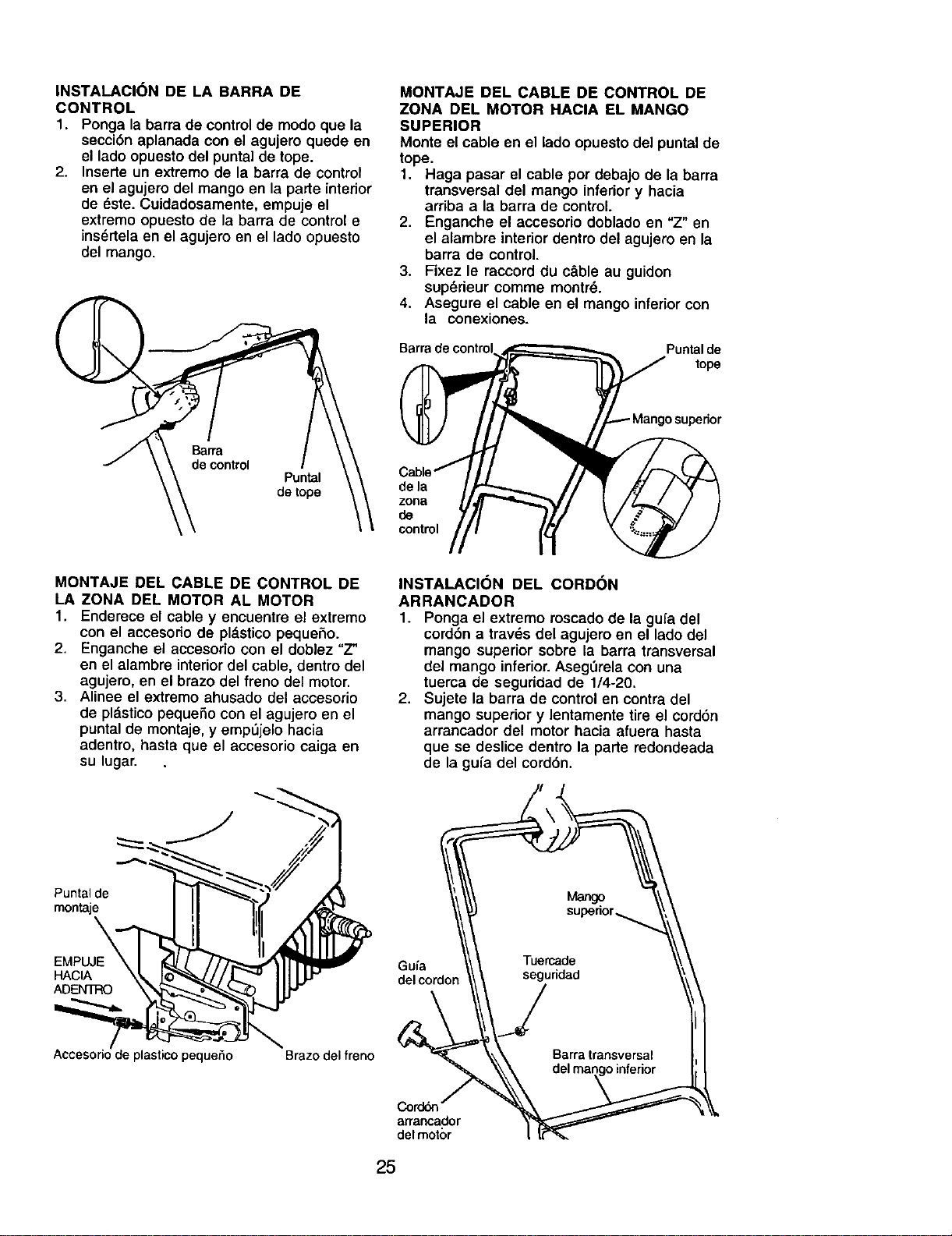
INSTALACION DE LA BARRA DE
CONTROL
1. Ponga la barra de controlde modo que la
secci6n aplanada con el agujero quede en
el ladoopuesto del punta]de tope.
2. Inserte un extremo de la barra de control
en el agujero del mango en la parte interior
de _ste. Cuidadosamente, empuje el
extremo opuesto de la barra de controle
ins_rtela en el agujero en el lado opuesto
del mango.
Puntal
de tope
MONTAJE DEL CABLE DE CONTROL DE
ZONA DEL MOTOR HACIA EL MANGO
SUPERIOR
Monte el cable en el lado opuesto del puntal de
tope.
1. Haga pasar el cable por debajo de la barra
transversal del mango inferior y hacia
arriba a la barra de control.
2. Enganche el accesorio doblado en "Z" en
el alambre interior dentro del agujero en la
barra de control.
3. Fixez le raccord du c&ble au guidon
sup_rieur comme montr_.
4. Asegure el cable en el mango inferiorcon
la conexiones.
Puntal de
tope
de la
zona
de
control
MONTAJE DEL CABLE DE CONTROL DE
LA ZONA DEL MOTOR AL MOTOR
1. Enderece el cable y encuentro el extremo
con el accesorio de pldsticopequeho.
2. Enganche el accesorio con el doblez =Z"
en el alambre interiordel cable, dentro del
agujero, en el brazo del freno del motor.
3. Alinee el extremo ahusado del accesorio
de pldstico peque_o con el agujero en el
puntal de montaje, y emp_jelo hacia
adentro, hasta que el accescrio caiga en
su lugar.
INSTALACION DEL CORDON
ARRANCADOR
1. Ponga el extremo roscado de la gufa del
cord6n a travds del agujero en el lado del
mango superior sobre la barra transversal
del mango inferior.Aseg,',relacon una
tuerca de seguridad de 1/4-20.
2. Sujete la barra de controlen contra del
mango superior y lentamente tire el cordon
arrancador del motor hacia afuera hasta
que se deslice dentro la parte redondeada
de la gufa del cord6n.
Puntalde
montaje
\
HACIA
ADENTRO
Gufa
del cordon
Accesorio de plastico pequeSo Brazo del freno
Cordbn
arrancador
delmotc)r
25
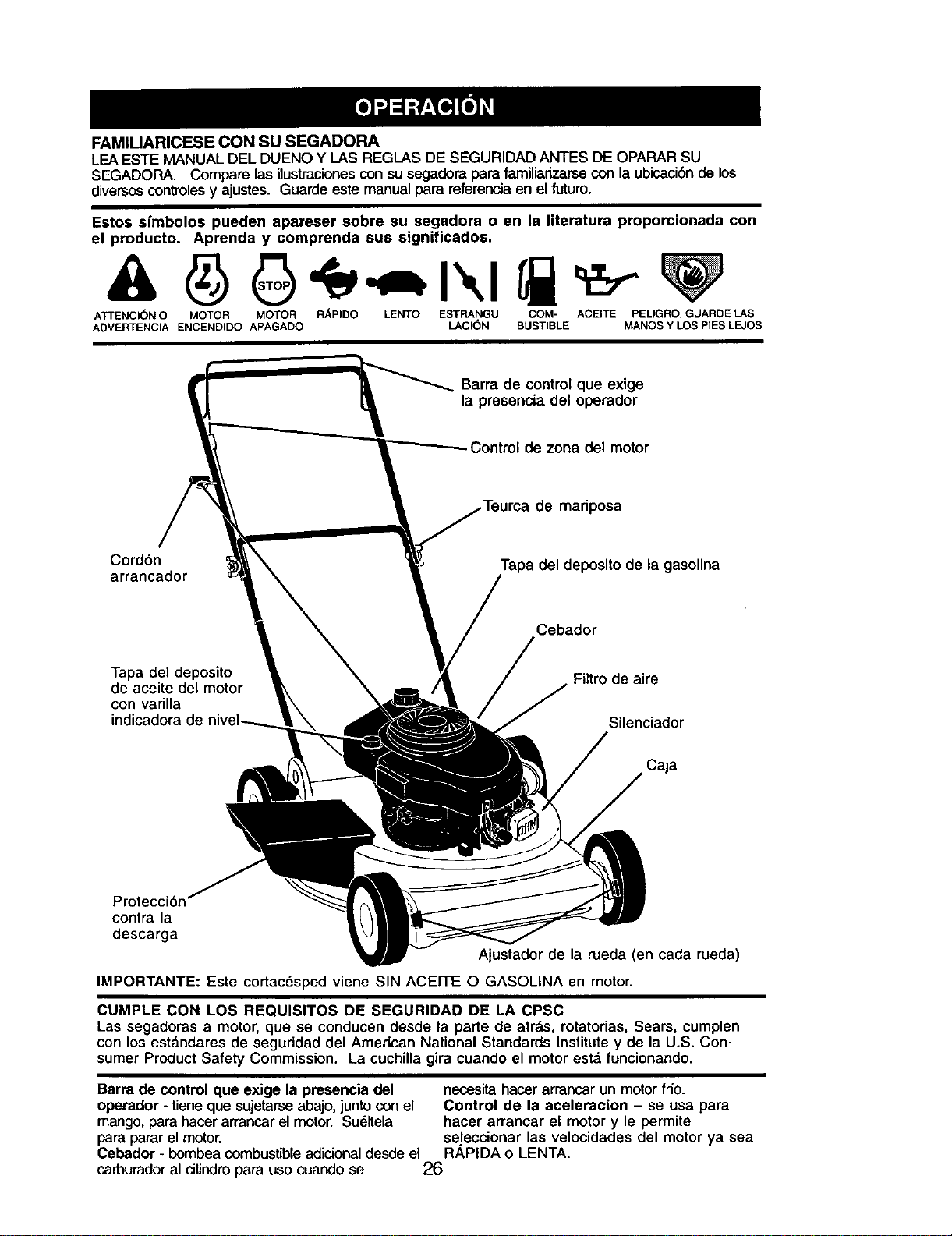
FAMIUARICESE CON SU SEGADORA
LEA ESTE MANUAL DEL DUENO Y LAS REGLAS DE SEGURIDAD ANTES DE OPARAR SU
SEGADORA. Compare lasilustracionescon su segadora para familiarizarse con la ubicaci6nde los
diversoscontroles y ajustes. Guarde este manualpara referencia en el futuro.
Estos sfmbolos pueden apareser sobre su segadora o en la literatura proporcionada con
el producto. Aprenda y comprenda sus significados.
ATTENCI(_N O MOTOR MOTOR R_,PIDO LENTO ESTRANGU COM- ACEITE PELIGRO, GUARDE LAS
ADVERTENCIA ENCENDIDO APAGADO LACI(_N BUSTIBLE MANOS Y LOS PIES LEJOS
Barra de control que exige
la presencia del operador
Control de zona del motor
de mariposa
Cord6n
arrancador
Tapa del deposito de la gasolina
Cebador
Tapa del deposito
de aceite del motor
con varUla
indicadora de
Filtro de aire
Silenciador
Caja
Protecci6n
contra la
descarga
Ajustador de la rueda (en cada rueda)
IMPORTANTE: Este cortacdsped viene SIN ACEITE O GASOLINA en motor.
CUMPLE CON LOS REQUISITOS DE SEGURIDAD DE LA CPSC
Las segadoras a motor, que se conduoen desde la parte de atrds, rotatorias, Sears, cumplen
con los est&ndares de seguridad del American National Standards Institutey de la U.S. Con-
sumer Product Safety Commission. La cuchilla gira cuando el motor estd funcionando.
Barra de control que exige la presencia del necesitahacor arrancar un motor frio.
operador - tieneque sujetarseabajo, juntocon el Control de la aceleracion - se usa para
mango,para hacorarrancarel motor. Su61tela hacer arrancar el motor y le permite
para pararel motor, selecoionar las velocidades del motor ya sea
Cebador - bombea combustible adicionaldesde el R/_PIDA o LENTA.
carburador al citindro para uso cuando se 26
La operacibn de cualquier
segadora puede hacer que
salten objetos extrahos dentro
de sus ojos, Io que puede
producir dahos graves en _stos.
Siempre use anteojos de seguridad o
protecci6n para los ojos mientras opere su
segadora o cuando haga ajustes o
reparaciones. Recomendamos gafas o una
mascara de seguridad de visi6n amplia de
seguddad usada sobre las gafas.
COMO USAR SU SEGADORA
VELOCIDAD DEL MOTOR
La velocidad del motor se estableci6 en la
f&brica para un rendimiento 6primo. La
velocidad no se puede ajustar.
CONTROL DE ZONA DEL MOTOR
_IPRECAUClON: Las regulaciones federales
exigen que se instale un controlpara el motor
en esta segadora para reducir a un minimo el
riesgo de lesionarse debido al contacto con la
cuchilla. Por ningdn motivotrate de eliminar la
funci6n del control del operador. La cuchilla
gira cuando el motor estd funcionando.
• Su segadora viene equipada con una barra
de controles que exigen la presencia del
operador, Io que requiem que el operador
estd detrds del mango de la segadora para
hacerla arrancar y operada.
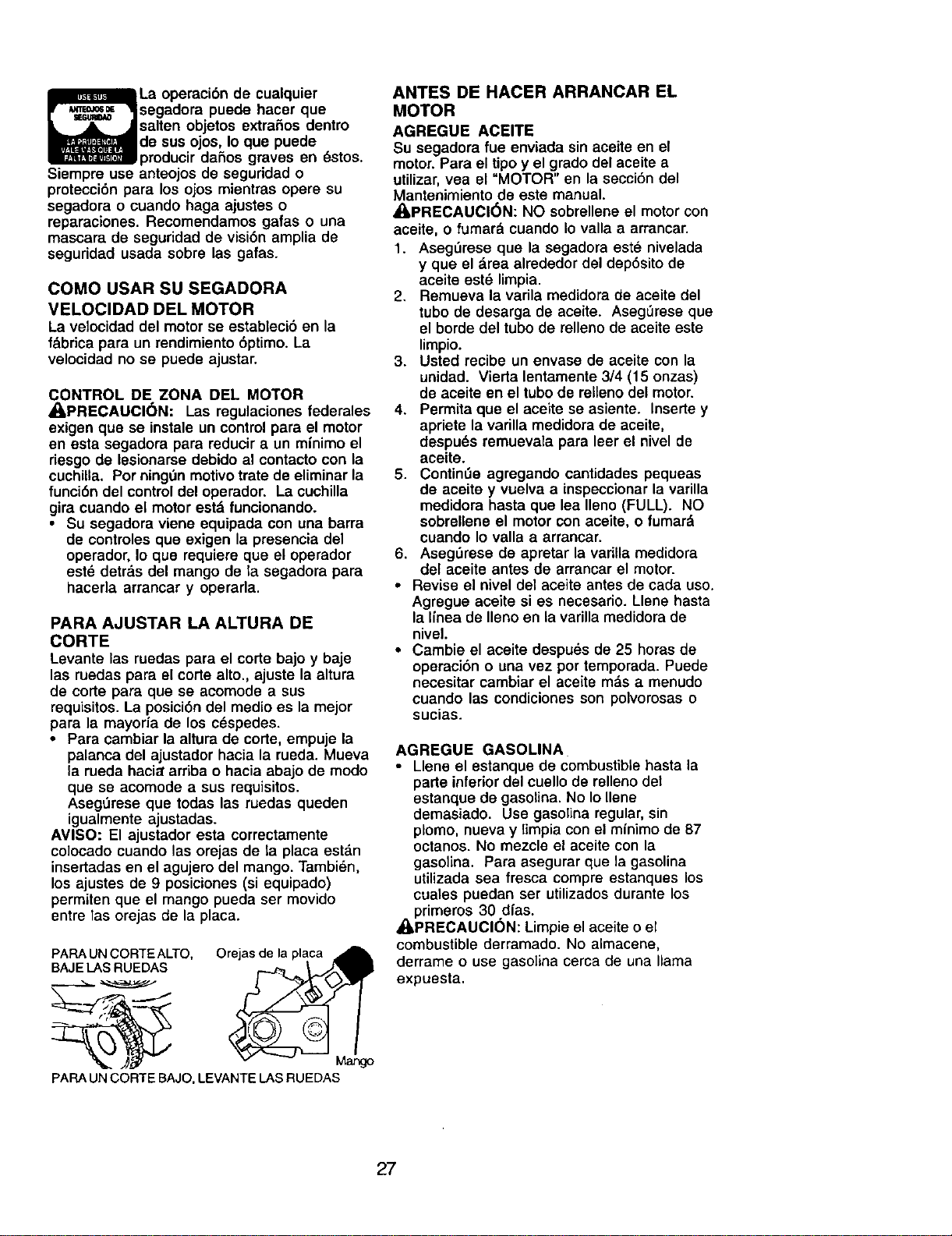
PARA AJUSTAR LA ALTURA DE
CORTE
Levante las ruedas para el corte bajo y baje
las ruedas para el corte alto., ajuste la altura
de corte para que se acomode a sus
requisitos.La posici6n del medio es la mejor
para la mayoria de los c_spedes.
• Para cambiar la altura de cone, empuje la
palanca del ajustador hacia la rueda. Mueva
la rueda haciararriba o hacia abajo de modo
que se acomode a sus requisitos.
Aseg0rese que todas las ruedas queden
igualmente ajustadas.
AVISO: El ajustador esta correctamente
co]ocado cuando las orejas de la placa est_.n
insertadas en el agujero del mango. Tambi_n,
los ajustes de 9 posiciones (si equipado)
permiten que el mango pueda ser movido
entre las orejas de la placa.
PARA UN CORTE ALTO, Orejas de la placa
BAJE LAS RUEDAS
PAPA UN CORTE BAJO, LEVANTE LAS RUEDAS
ANTES DE HACER ARRANCAR EL
MOTOR
AGREGUE ACEITE
Su segadora fue enviada sin aceite en el
motor. Para el tipo y el grado del aceite a
utilizar,vea el "MOTOR" en la secci6n del
Mantenimiento de este manual.
_PRECAUCI6N: NO sobrellene el motorcon
aceite, o fumard cuando io valla a arrancar.
1. Aseg_rese que la segadora este nivelada
y que el area alrededor del dep6sito de
aceite est6 limpia.
2. Remueva la varila medidora de aceite del
tube de desarga de aceite. AsegLireseque
el borde del tubo de rellenode aceite este
limpio.
3. Usted recibe un envase de aceite con la
unidad. Vierta lentamente 3/4 (15 onzas)
de aceite en el tube de rellenodel motor.
4. Permita que el aceite se asiente. Inserte y
apriete la varilla medidora de aceite,
despu_s remuevala para leer el nivel de
aceite.
5. Contin0e agregando cantidades pequeas
de aceite y vuelva a inspeccionarla varilla
medidora hasta que lea Ileno (FULL). NO
sobrellene el motorcon aceite, o fumard
cuando Io valla a arrancar.
6. Aseg_rese de apretar la variUa medidora
del aceite antes de arrancar el motor.
• Revise el nivel del aceite antes de cada uso.
Agregue aceite si es necesario. Llene hasta
la Ifnea de Ileno en la varilla medidora de
nivel.
• Cambie el aceite despues de 25 horas de
operaci6n o una vez por temporada. Puede
necesitar cambiar el aceite mds a menudo
cuando las condiciones son polvorosas o
sucias.
AGREGUE GASOLINA
• Llene el estanque de combustible hasta la
parte inferiordel cuello de rellenodet
estanque de gasolina. No Io Ilene
demasiado. Use gasolina regular, sin
plomo, nueva y limpia con el mfnimo de 87
octanos. No mezcle el aceite con la
gasolina. Para asegurar que la gasolina
utilizada sea fresca compre estanques los
cuales puedan ser utilizadosdurante los
primeros 30 dfas.
_PRECAUCl6N: Limpie el aceite o el
combustible derramado. No almacene,
derrame o use gasolina cerca de una llama
expuesta.
27
APRECAUCl6N- Los combustibles
mezclados con alcohol (conocidos como
gasohol, o el uso de etanol o metanol) pueden
atraer la humedad, la que conduce a la
separaci6n y formaci6n de &cidos durante el
almacenamiento. La gasolina ac[dica puede
claSarel sistema del combustible de un motor
durante el aimacenamiento. Para evitar los
problemas con el motor, se debe vaciar et
sistema del combustible antes de guardarlo
por un periodo de 30 dfas o m&s. Vacfe el
estanque del combustible, haga arrancar el
motor y h&galofuncionar hasta que las lineas
del combustible y el carburador queden
vacios. La pr6xima temporada use
combustible nuevo. Vea las Instrucciones Para
El Almacenamiento para mds informaci6n.
Nunca use productos de limpieza para el
motor o para el carburador en el estanque del
combustible pues se pueden producir daSos
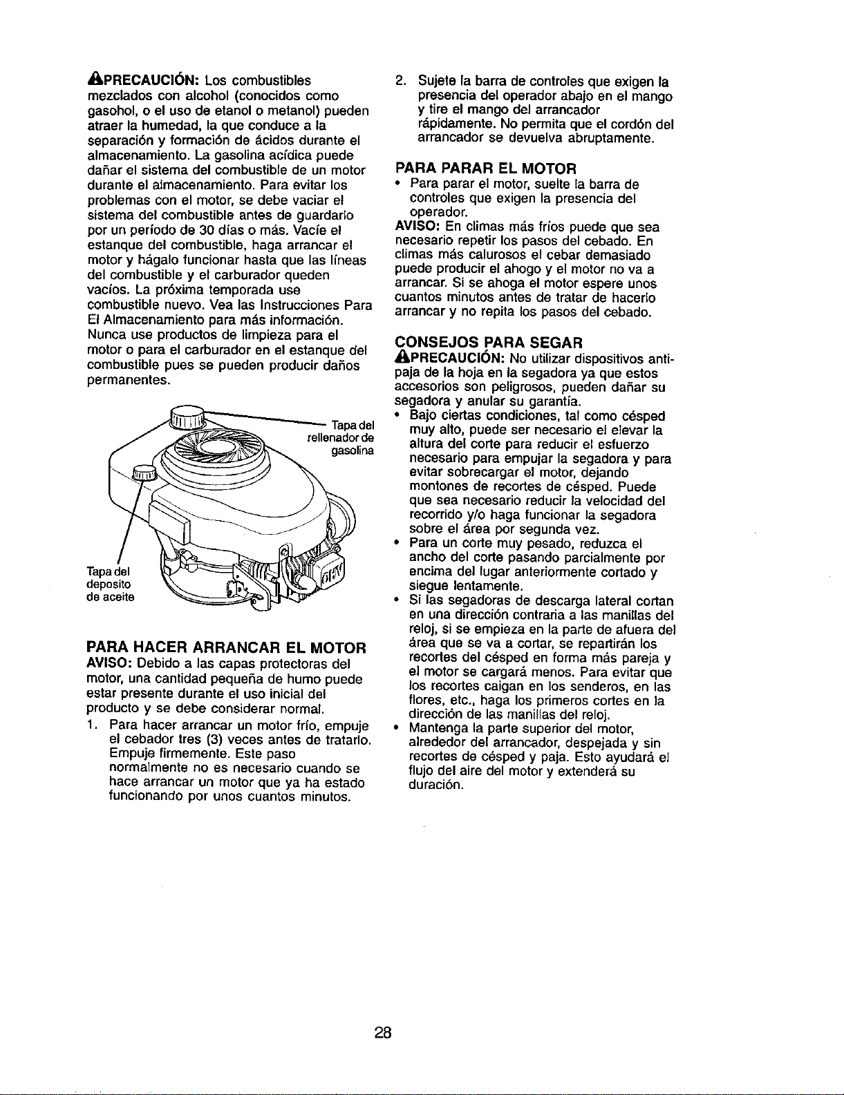
permanentes.
Tapadel
rellenadorde
gasolina
Tapadel
deposito
de aceite
PARA HACER ARRANCAR EL MOTOR
AVISO: Debido alas capas protectoras del
motor, una cantidad pequeSa de humo puede
estar presente durante el uso inicialdel
producto y se debe considerar normal.
1. Para hacer arrancar un motor frio, ernpuje
el cebador ires (3) veces antes de tratarlo.
Empuje firrnemente. Este paso
normalmente no es necesario cuando se
hace arrancar un motor que ya ha estado
funcionando por unos cuantos minutos.
2.
Sujete la barra de controles que exigen la
presencia del operador abajo en el mango
y tire el mango del arrancador
r&pidamente. No permita que el cord6n del
arrancador se devuelva abruptamente.
PARA PARAR EL MOTOR
• Para parar el motor, suelte la barra de
controles que exigen la presencia del
operador.
AMISO: En climas m&s fdos puede que sea
necesario repetir los pasos del cebado. En
climas mds caluresos el cebar demasiado
puede producir el ahogo y el motor no va a
arrancar. Si se ahoga el motor espere unos
cuantos minutos antes de tratar de haeerlo
arranoar y no repita los pasos del cebado.
CONSEJOS PARA SEGAR
_I, PRECAUCI(_N: No utiUzardispositivos anti-
paja de la hoja en la segadora ya que estos
accesorios son peligrosos, pueden daSar su
segadora y anular su garantia.
• Bajo ciertas condiciones, tal como cdsped
muy alto, puede ser necesario el elevar la
altura del corte para reducir el esfuerzo
necesario para empujar la segadora y para
evitar sobrecargar el motor, dejando
montones de recortes de cdsped. Puede
que sea neeesario reducir la velocidad del
recorrido y/o haga funcionar la segadora
sobre el &rea pot segunda vez.
• Para un corte muy pesado, reduzca el
ancho del corte pasando parcialmente por
encima del lugar anteriormente corlado y
siegue lentamente.
• Si las segadoras de descarga lateral cortan
en una direcci6n contrariaalas manillas del
reloj, sise empieza en la parte de afuera del
&rea que se va a cortar, se repartir&nlos
recortes del c_sped en forma m&s pareja y
el motorse cargar& menos. Para evitar que
los recortes caigan en los senderos, en las
flores, etc., haga los primeros cortes en la
direcci6n de las manillas del reloj.
• Mantenga la parte superior del motor,
alrededor del arrancador, despejada y sin
recortes de c_sped y paja. Esto ayudar& el
flujo del aire del motory extender& su
duraci6n.
28
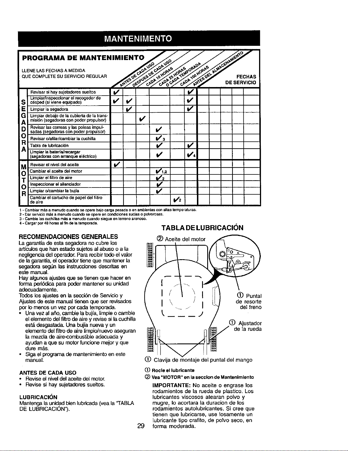
PROGRAMA DE MANTENIMIENTO /_JJ J_J
,=c.,s
Revisar sihay sujetadores sueltos If V'
Limpiar/inspeccionarel recogedor de
I c_sped (si viene equipado) If _._ V'
Limpiar lasegadora
I Limpiardebajo de la cubierta de la transo
misibn (segadoras con poder propulsor)
I Revisar las correas y las poleas impul-
sadas (segadoras con poder propulsor) If
Revisar o/afilar/cambiar la cuchilla li_ 3
I Tabla de Iubricaci6n If V /
Umpiar la bateria/recargar
(segadoras con arranque el_ctrico) Ik/ V'4
M Revisar el nivel del aceite I_
O Cambiar el aceite del motor Ikflvr2_
Limpiar el fltro de aim
Inspeccionarel silenciador
I Limpiar o/cambiar la bujia
Cambiar el cartucho de papel del fiJtro _2
de aire
1 * Cambiar m_s a menudo cuando so opere bajo carga pesada o en ambientes con alias temperaturas.
2 ° Dar se_k;io i1_s a Ir_13u_o cua_Jo se opgre e_3COP_iicionessucJaso polvotosas.
3 ° Cambie las cuch_llasm_tsa rnenudo cuando sieguB en lerreno arenoso.
4" Cargar por 48 horns al fin de la ternporada. TAB LA DE LU BRICACION
RECOMENDACIONES GENERALES
La garantiade esta segadorano cubrelos
arlculosque hartestadosujetosal abusoo a la
negligenciadeloperader.Pararecibirtodoelvalor
de lagarantia,eloperadortieneque mantener la
segadera seg_n las instrucciones descritas en
este manual.
Hay algunos ajustes que se tienen que hacer en
forma pedbdica para poder mantener su unidad
adecuadamente.
Todos los ajustes en la secci6n de Servicio y
Ajustes de es_ manual tienen que set revisados
por Io menos un vez por cada temporada.
• Unavez al a£1o,cambie la bujia, limpieo cambie
et elementodel filtrode aire y revise si la cuchila
est_ desgastada. Una bujia nueva y un
elemento del filtro de alre limpio/nuevo aseguran
la mezcla de aire-combustble adecuada y
ayudan a que su motor funcione mejor y que
dure m_s.
• Siga el programa de mantenimiento en este
manual.
(_) Aceite del motor
I
I
I
(_) Puntal
de resorte
deI freno
(_) Ajustador
de Ia rueda
(_) Clavija de montaje del puntal del mango
ANTES DE CADA USO
• Reviseel niveldel aceitedeI motor.
• Revisesi hay sujetadoressueltes.
LUBRICACION
Mantenga la unid.adbien lubricada(yea la "TABLA
DE LUBRICACION").
1_ Rocle el lubrlcante
Vea "MOTOR" en la secclon de Mantenlmlento
29
IMPORTANTE: No aceite o engrase los
rodamientos de la rueda de plastico. Los
lubricantes viscosos atearan polvo y
mugre, Io acortara la duracion de los
rodamientos autolubricantes. Si cree que
tienen que lubricarse, use Iosamente un
lubrloante tipo crafito, de poIvo seeo, en
forma moderada.
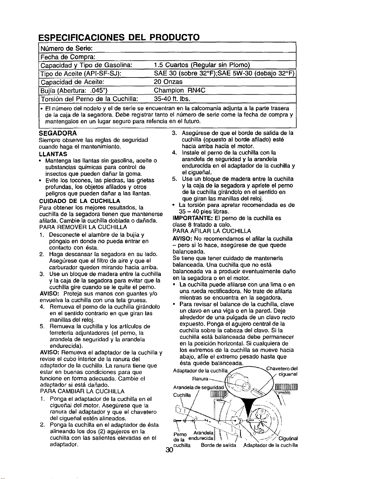
ESPECIFICACIONES DEL PRODUCTO
Nl_mero de Serie:
Fecha de Compra:
Capacidad y Tipo de Gasolina: 1.5 Cuartos (Regular sin Plomo)
Tipo de Aceite (API-SF-SJ): SAE 30 (sobre 32°F);SAE 5W-30 (debajo 32°F)
Capacidad de Aceite: 20 Onzas
Bujia (Abertura: .045") Champion RN4C
Torsi6n del Perno de la Cuchilla: 35-40 ft. Ibs.
El n0mero del nodelo y el de serie se encuentran en la calcomania adjunta a la parte trasera
de la caja de la segadora. Debe registrar tanto el nOmero de serie come la fecha de compra y
mantengalos en un lugar seguro para refencia en el futuro.
SEGADORA
Siempre observe las reglas de seguridad
cuando haga el mantenimianto.
LLANTAS
• Mantenga las Ilantas sin gasolina, aceite o
substancias quimicas para control de
insectos que pueden daSar la goma.
• Evite los tocones, las piedras, las grietas
profundas, los objetos afilados y otros
peligros que pueden daSar alas Ilantas.
CUIDADO DE LA CUCHILLA
Para obtener los rnejores resultados, la
cuchillade la segadora tienen que mantenerse
afilada. Cambie la cuchilla doblada o daSada.
PARA REMOVER LA CUCHILLA
1. Desconecte el alambre de la bujia y
p6ngalo en donde no pueda entrar en
contacto con _sta.
2. Haga descansar la segadora en su lado.
AsegL_rese que el filtro de aire y que el
carburador queden mirando hacia arriba.
3. Use un bloque de madera entre la cuchilla
y la caja de la segadora para evitar que la
cuchilla gire cuando se le quite el perno.
AVISO: Proteja sus manos con guantes y/o
envuelva la cuchilla con una tela gruesa.
4. Remueva el perno de la cuchilla girandolo
en el sentido contrario en que giran las
manillas del reloj.
5. Remueva la cuchilla y los artfculos de
ferreteria adjuntadores (el perno, la
arandela de seguridad y la arandela
endurecida).
AVI50: Remueva el adaptador de la cuchilla y
revise el cube interior de la ranura del
adaptador de la cuchilla. La ranura tiene que
estar en buenas condiciones para que
funcione en forma adecuada. Cambie el
adaptador si esta daSado.
PARA CAMBIAR LA CUCHILLA
1. Ponga el adaptador de la cuchilla en el
cigue,_al del motor. Aseg0rese que la
ranura del adaptador y que el chavetero
del cigueSal est_n alineados.
2. Ponga la cuchilla en el adaptador de _sta
alineando los dos (2) agujeros en la
cuchilla con las salientes elevadas en el
adaptador.
3. Aseg_rese de que el borde de salida de la
cuchilla (opuesto al borde afilado) est_
hacia arriba hacia el motor.
4. Instale el perno de la cuchilla con la
arandela de seguridad y la arandela
endurecida en el adaptador de la cuchilla y
el cigue_al.
5. Use un bloque de madera entre la cuchilla
y la caja de la segadora y apriete el perno
de la cuchillagir&ndoloen el sentido en
que giran las manillas del reloj.
• La torsi6n para apretar recomendada es de
35 - 40 pies libras.
IMPORTANTE: El perno de la cuchilla es
clase 8 tratado a calo.
PARA AFILAR LA CUCHILLA
AVISO: No recomendamos el afilar la cuchilla
- pero si tohace, aseg0rese de que quede
balanceada.
Se tiene que tener cuidade de manteneria
balanceada. Una cuchilla que no est&
balanceada va a producir eventualmente daSo
en la segadora o en el motor.
• La cuchilla puede afilarse con una lima o en
una rueda rectificadora. No trate de afilarla
mientras se encuentra en la segadora.
• Para revisar el balance de la cuchilla, clave
un clavo en una viga o en la pared. Deje
alrededor de una pulgada de un clavo recto
expuesto. Ponga el agujero central de ta
cuchil]a sobre la cabeza del clavo. Si la
cuchilla est& balanceada debe permanecer
en la posici6n horizontal. Si cualquiera de
los extremos de la cuchilla se mueve hacia
abajo, afile el extremo pesado hasta que
_sta quede balanceada.
Chaveterodel
Cuchilla
Perno Arandela
de la endurecida / Ciguonal
cuchilla Bordedesalida Adaptadordelacuchilla
3O

MOTOR
LUBRICACION
Usesolamente aseitede detergente de alta
calidad clesificado con la clesificaci6n SF-SJ de
servicio API. Seleccione la calidad de viscosidad
SAE segt_nsu temperature de operaci6n
esperada.
AVISO" A pesarde que los aceites de
multiviscosidad (5W30, 10W30, etc.) mejoran el
arranqueen climafdo, estosaceitesde
multiviscosidad van ha aumentarel consume de
aseite cuandose usanen temperaturassobre32°
F. Reviseel niveldel aceite delmotorm&sa
menudo,para evitarun posibleda_o an el motor,
debidoa que no tienesuficienteaseite.
Cambieel aceitedespuesde 25 horasde
operaci6no porIo menosunavez al aSosila
segadorase utilizamenos 25 horasel aSo.
Reviseel niveldel aceitedel cdrterantes de
arrancarel motory despu6sde cada cinco(5)
horasdeuso continuado.Apriete eltap6ndel
aseite en forma seguracada vez que reviseel
niveldel aceite.
PARA CAMBIAR EL ACEITE DEL MOTOR
AVISO: Antes de inclinar la segadora para
drenar el aceite, drene el tanque de combus-
tible haciendo correr et motor hasta que el
tanque est_ vacio.
1. Desconecte el alambre de la bujia y
pongalo de modo que no pueda entrar en
contacto con _sta.
2. Remueva la tapa del dep6sito del aceite;
dejela a un lade en una superficie limpia.
3. Incline la cortadora de c6sped por este
costado tal como se muestra y purgue el
aceite en un recipiente idbneo. Mueva la
segadora de atr&s para adelante para
remover todo el aceite que se haya
quedade atrapado dentro del motor.
4. Limpie todo el aceite derramado en la
segadora yen el lado del motor.
5. Rellene el motor con aceite. (Vea "PARA
AGREGAR EL ACEITE" en la secci6n de
Operaci6n de este manual.)
6. Vuelva a conectar el alambre de la bujia a
esta.
FILTRO DE AIRE
Su motor puede sufrir averias y funcionar de
manera incorrecta con un flltrodel aire sucio.
Sustituir el papel del cartucho una vez al aSo o
tras 100 horas de funcionamiento, rods a
menudo si se utiliza en condicionesde
suciedad y polvo particulares. No lave el filtro
de aire.
PARA CAMBIAR EL FILTRO DE AIRE
1. Remueva el filtro de aire gir&ndoloen el
sentido contrario en que giran las manillas
del reloj, hasta el tope, y retirelodel collar.
2. Remueva el filtrode la parte interior de la
cubierta.
3. Limpie la parte interior de la cubierta y el
collar para remover toda acumulacibn de
mugre.
4. Inserte el filtro nuevo en la cubierta.
5. Ponga la cubierta del filtro de aire dentro
del collar alineando la oreja con la ranura.
6. Empuje la cubierta hacia adentre y girela
en el sentido de las manillas del reloj para
apretarla.
Collar Abrazadera G
CONTRARIO AI.AS
MANILLAS
DEL
RELOJ
PAPA
REMOVER
Rsnura
Filtm de aire , GIRE EN EL
Oreja _ENT1DODE
LASMANILLAS
Cubierta del filtro de aire DEL RELOJPARAAPRETAR
SILENCIADOR
Inspeccione y cambie el silenciador si est&
corroido puede producirun peligro de incendio
y/o daSo.
BUJiA
Cambie el bujia al comienzo de cada
temporada de siega o despu_s de cada 100
horas de operacion, Io que suceda primero. El
tipo de buj_ay el ajuste de la abertura
aparecen en "ESPECIFICACIONES DEL
PRODUCTO" en la secci6n de Mantenimiento
de este manual,
LIMPIEZA
IMPORTANTE: Para obtener el mejor
rendimiento, mantenga la caja de la segadora
sin acumulacion de cesped y basura. Limpinla
parte de abajo de su segadora despues de
cada uso.
_qLPRECAUCION: Desconecte el alambre de
la bujia y pongalo en donde no pueda entrar
en contacto con _sta.
• Limpie la parte inferior de su segadora
raspdndola para remover la acumulacibn de
c_sped y basura.
31
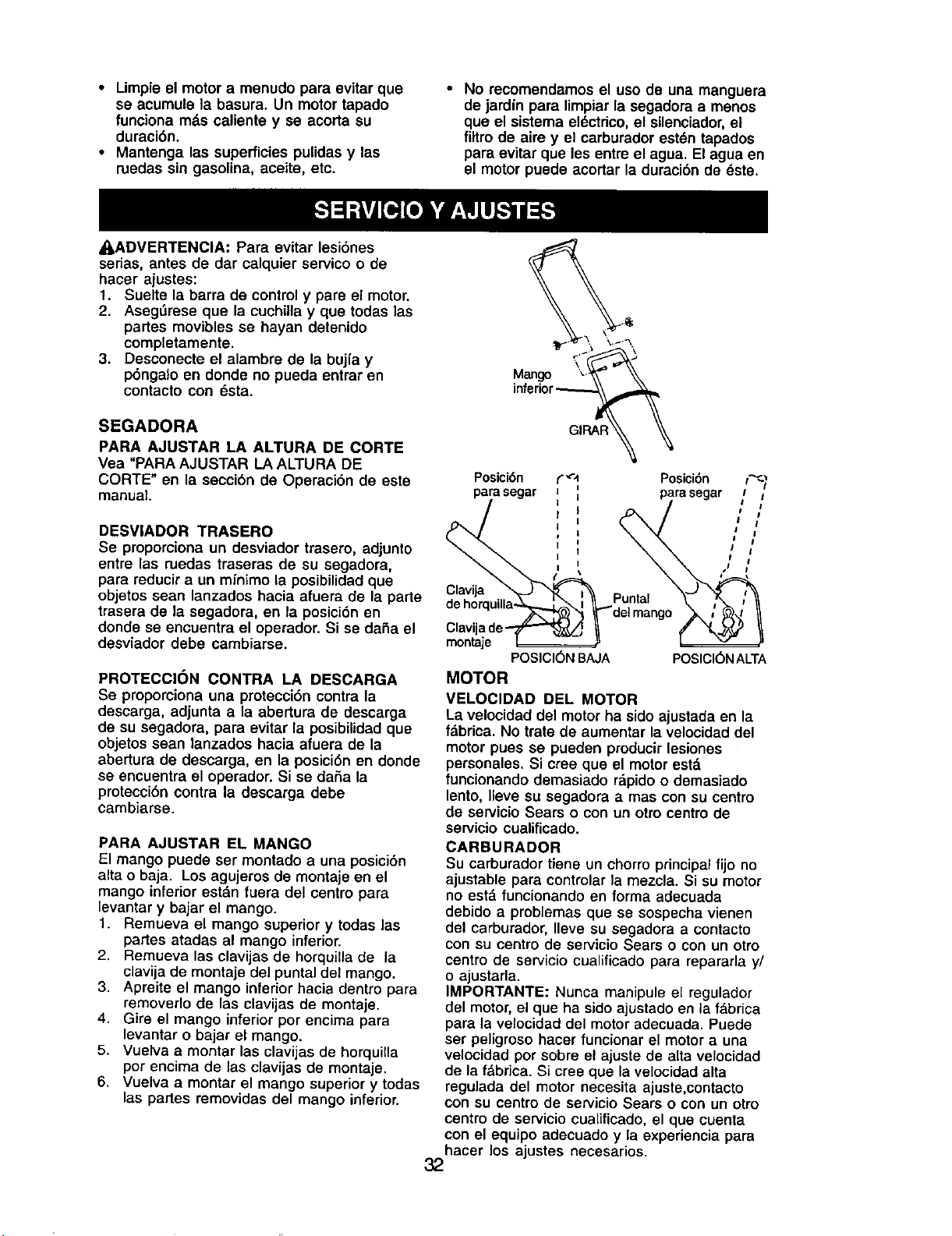
• Limpie el motor a menudo para evitar que
se acumule la basura. Un motor tapado
funciona m_.s caliente y se acorta su
duraci6n.
• Mantenga las superficies pulidas y las
ruedas sin gasolina, aceite, etc.
• No recomendamos el uso de una manguera
de jardin para limpiarla segadora a manos
que el sistema el_ctdco, el silenciador,el
filtro de aire y el carburador est_n tapados
para evitar que les entre el agua. El agua en
el motor puede acortar la duraci6n de _sta.
_,ADVERTENClA; Para evitar lesi6nes
sedas, antes de dar calquier servico o de
hacer ajustes:
1. Suelte la barra de control y pare el motor.
2. AsegSrese que la cuchilla y que todas las
partes movibles se hayan detenido
completamente.
3. Desconecte el alambre de la bujfa y
p6ngalo en donde no pueda entrar en
contacto con 6sta.
SEGADORA
PARA AJUSTAR LA ALTURA DE CORTE
Vea "PARA AJUSTAR LA ALTURA DE
CORTE" en la seccibn de Operaci6n de este
manual.
DESVIADOR TRASERO
Se proporciona un desviador trasero, adjunto
entre las ruedas traseras de su segadora,
para reducir a un mJnimo la posibilidad que
objetos sean lanzados hacia afuera de la parte
trasera de la segadora, en la posici6n en
donde se encuentra el operador. Si se daha el
desviador debe cambiarse.
PROTECCION CONTRA LA DESCARGA
Se proporciona una protecci6n contra la
descarga, adjunta a la abertura de descarga
de su segadora, para evitar la posibilidad que
objetos sean lanzados hacia afuera de la
abertura de descarga, en la posici6n en donde
se encuentra el operador. Si se daSa la
proteccibn contra la dascarga debe
cambiarse.
PARA AJUSTAR EL MANGO
El mango puede ser montado a una posici6n
alta o baja. Los agujeres de montaja en el
mango inferior estfm fuera del centro para
levantar y bajar el mango.
1. Remueva el mango superior y todas las
partes atadas al mango inferior,
2. Remueva las clavijas de horquilla de la
clavija de montaje del puntal del mango.
3. Apreite el mango inferior hacia dentro para
removerlo de las clavijas de montaje.
4. Gire el mango inferior por encima para
levantar o bajar el mango.
5. Vuelva a montar las clavijas de horquilla
por encima de las clavijas de montaje.
6. Vuelva a montar el mango superior y todas
las partes removidas del mango inferior•
\.f_.
Mango _::_
inferior_GIRAP
Posici6n t"_',1 Posici6n t_
parasegar J parasegar t /
• # i
I j I
I i I t
i I l !
, , ,,'
" ,_%_'_ ) _ aelmango _ ! N_ II
Clavijade'--_-"_-_ _ _" "_._'_ II
montaje I= ,_
POSICI6NBAJA POSICI6NALTA
MOTOR
VELOClDAD DEL MOTOR
La velocidad del motor ha sido ajustada en la
fabrica. No trate de aumentar la velocidaddel
motor pues se pueden producir lesionos
personales. Si cree que el motor est,.
funciooando demasiado r_,pidoo demasiado
lento, Ileve su segadore a mas con su centro
de servicio Sears o coo un otto centre de
servicio cualificado.
CARBURADOR
Su carburador tiene un chorro principalfijo no
ajustable para controlar la mezcla. Si su motor
no est& funcionando en forma adecuada
debido a problemas qua sa sospecha vienen
del carburador, Ileve su segadore a contacto
con su centro de servicio Sears o con un otro
centro de servicio cualificado para repararla y/
o ajustarla.
IMPORTANTE: Nunca manipule el regulador
del motor, el qua ha sido ajustado en la f&brica
para la velocidad del motoradecuada. Puede
ser peligroso hacer funcionar el motor a una
velocidad por sobre el ajuste de alia velocidad
de la f&brica. Si cree qua lavelocidad alta
regulada del motor necesita ajuste,contacto
con su centro de servicio Sears o con un otro
centre de servicio cualificado, el que cuenta
con el equipo adecuado y la experiencia para
hacer los ajustes necesarios.
32
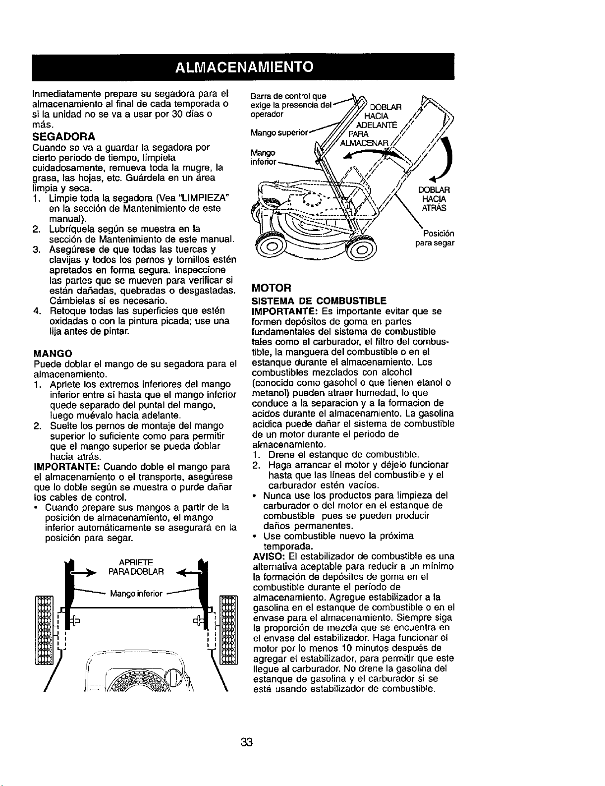
Inmediatamente prepare su segadora para el
almacenamiento al final de cada temporada o
si la unidad no se va a usar por 30 dias o
m_s.
SEGADORA
Cuando se va a guardar la segadora por
cierto periodo de tiempo, [_mpiela
cuidadosamente, remueva toda la mugre, la
grasa, las hojas, etc. Gu_.rdelaen un area
limpia y seca.
1. Limpie toda la segadora (Vea "LIMPIEZA"
en la secci6n de Mantenimiento de este
manual).
2. Lubrfquela seg_n se muestra en la
secci6n de Mantenimiento de este manual.
3. Aseg_rese de que todas las tuercas y
clavijas y todos los pernos y tornillosest_n
apretados en forma segura. Inspeccione
las partes que se mueven para verificar si
estdn dahadas, quebradas o desgastadas.
Cdmbielas si es necesario.
4. Retoque todas las superficies que est_n
oxidadas o con la pintura picada; use una
lijaantes de pintar.
MANGO
Puede doblar el mango de su segadora para el
almacenamiento.
1. Apriete los extremos inferioresdel mango
inferior entre s_hasta que el mango inferior
quede separado del puntal del mango,
luego mu_valo hacia adelante.
2. Suelte los pernos de montaje del mango
superior Io suficiente como para permitir
que el mango superior se pueda doblar
hacia arras.
IMPORTANTE: Cuando doble el mango para
el almacenamiento o el transporte, asegSrese
que Io doble segQn se muestra o purde daSar
los cables de control.
• Cuando prepare sus mangos a partir de la
posici6n de almacenamiento, el mango
inferior automdticamente se asegurar_, en la
posiciSn para segar.
APRIETE
PAPADOBLAR
Mango inferior
:lue
operador
Mang
Mango
DOBLAR
HACIA
ATPJ_
Posici6n
para segar
MOTOR
SISTEMA DE COMBUSTIBLE
IMPORTANTE: Es importante evitar que se
formen dep6sitos de goma en partes
fundamentales del sistema de combustible
tales como el carburador, el filtro del combus-
tible, la manguera del combustibleo en el
estanque durante el almacenamiento. Los
combustibles mezclados con alcohol
(conocido como gasohol o que tienen etanol o
metanol) pueden atraer humedad, Io que
conduce a la separacion y a la formacionde
acidos durante el almacenamiento. La gasolina
acidica puede daSar el sistema de combustible
de un motor durante el periodo de
almacenamiento.
1. Drene el estanque de combustible.
2. Haga arrancar el motor y dejelo funcionar
hasta que las Ifneas del combustible y el
carburador esten vacios.
• Nunca use los productos para limpieza del
carburador o del motor en el estanque de
combustible pues se pueden producir
dar_os permanentes.
• Use combustible nuevo la pr6xima
temporada.
AMISO: El estabilizador de combustible es una
alternativa aceptable para reducir a un minimo
la formaci6n de dep6sitos de goma en el
combustible durante el periodo de
almacenamiento. Agregue estabiiizador a la
gasolina en el estanque de combustible o en el
envase para el almacenamiento. Siempre siga
la proporci6n de mezcla que se encuentra en
el envase del estabilizador. Haga funcionar el
motor por Io menos 10 minutos despuds de
agregar el estabilizador, para permitir que este
Ilegue al carburador. No drene la gasolina del
estanque de gasolina y el carburador si se
esta usando estabilizador de combustible.
33
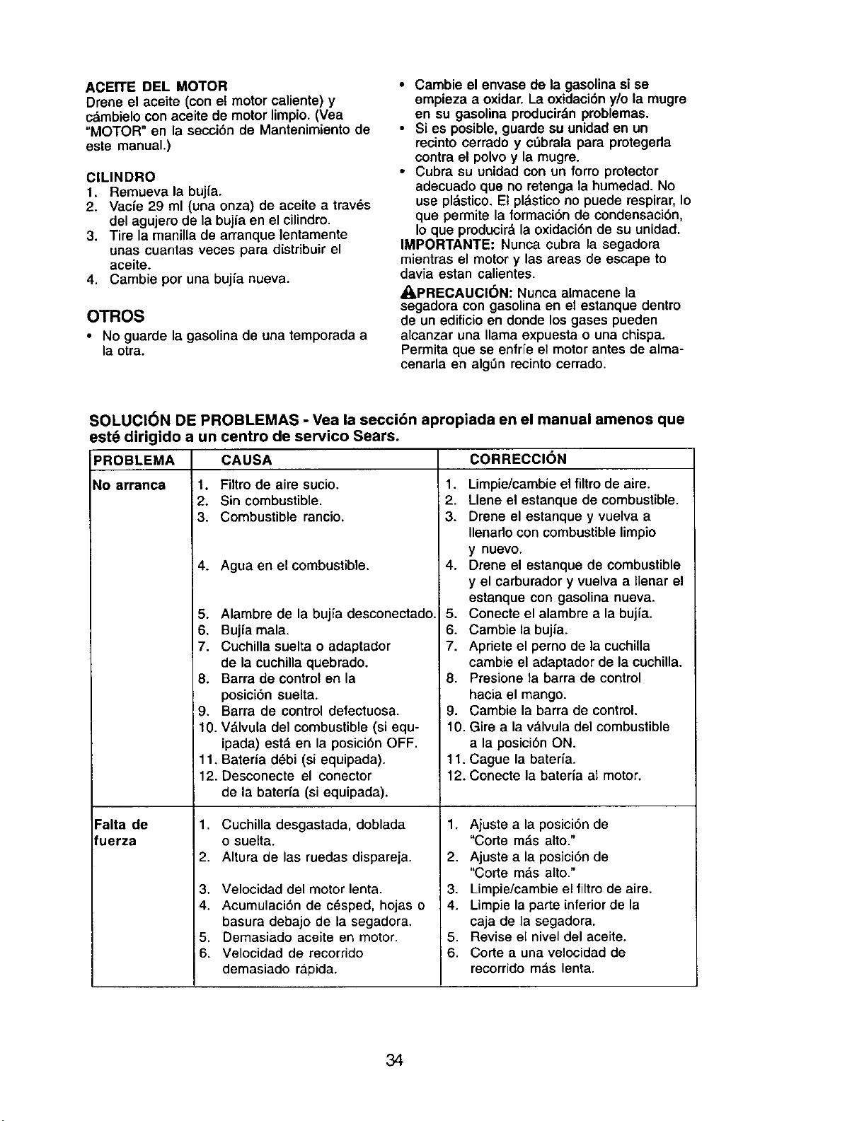
AcErrE DEL MOTOR
Drene el aceite (con el motor caliente) y
cdmbielo con aceite de motor limpio. (Vea
"MOTOR" en la secci6n de Mantenimiento de
este manual.)
ClLINDRO
1. Remueva la buj[a.
2. Vacie 29 ml (una onza) de aceite a tray,s
del agujero de la buj_aen el cilindro.
3. Tire la manilla de arranque lentamente
unas cuantas veces para distribuir el
aceite.
4. Cambie por una bujia nueva.
OTROS
• No guarde la gasolina de una temporada a
la otra.
• Cambie el envase de la gasolina si se
empieza a oxidar. La oxidacibny/o la mugre
en su gasolina pmducir&n problemas.
• Si es posible, guarde su unidad en un
recinto cerrado y c_brala para protegeda
contra el polvo y la mugre.
• Cubra su unidad con un forro protector
adecuado que no retenga la humedad. No
use pl&stico.Et pl_.sticono puede respirar, Io
que permite la formaci6n de condensaci6n,
Io que producir&la oxidaci6nde su unidad.
IMPORTANTE: Nunca cubra la segadora
mientras el motor y las areas de escape to
davia estan calientes.
_I, PRECAUCION: Nunca almacene la
segadora con gasolina en el estanque dentro
de un edificioen donde los gases pueden
alcanzar una llama expuesta o una chispa.
Permita que se enfrfe el motor antes de alma-
cenarla en algLinrecinto cerrado.
SOLUCl6N DE PROBLEMAS - Vea la secci6n apropiada en el manual amenos que
est6 dirigido a un centro de servico Sears.
CAUSAPROBLEMA
No arranca 1.
2.
3.
4.
5.
6.
7.
8.
Falta de
fuerza
Filtro de aire sucio.
Sin combustible.
Combustible rancio.
Agua en el combustible.
Alambre de la bujfa desconectado.
Bujfa mala.
Cuchilla suelta o adaptador
de la cuchilla quebrado.
Barra de control en la
posici6n suelta.
9. Barra de control defectuosa.
10. V&lvula del combustible (si equ-
ipada) est& en la posici6n OFF.
11. Bateria d_bi (si equipada).
12. Desconecte el conector
de la baterfa (si equipada),
1, Cuchilla desgastada, doblada
o suelta.
2. Altura de las ruedas dispareja.
3. Velocidad del motor lenta.
4. Acumulaci6n de c_sped, hojas o
basura debajo de la segadora.
5. Demasiado aceite en motor.
6. Velocidad de recorrido
demasiado ra.pida.
CORRECCION
1. Limpie/cambie el filtrode aire.
2. Llene el estanque de combustible.
3. Drene el estanque y vuelva a
Ilenado con combustible limpio
y nuevo.
4. Drene el estanque de combustible
y el carburador y vuelva a lienar el
estanque con gasolina nueva.
5. Conecte el alambre a la bujia.
6. Cambie la bujia.
7. Apriete el perno de la cuchilla
cambie el adaptador de la cuchilla.
8. Presione la barra de control
hacia el mango.
9. Cambie la barra de control.
10. Gire a la v&lvula del combustible
a la posici6n ON.
11. Cague la bateria.
12. Conecte la bateria al motor.
1. Ajuste a la posici6n de
"Code m_.salto."
2. Ajuste a la posici6n de
"Code m&s alto."
3. Limpie/cambie el filtro de aire,
4. Limpie la parte interior de la
caja de la segadora,
5. Revise el nivel del aceite.
6. Code a una velocidad de
recorrido m_.s lenta,
34
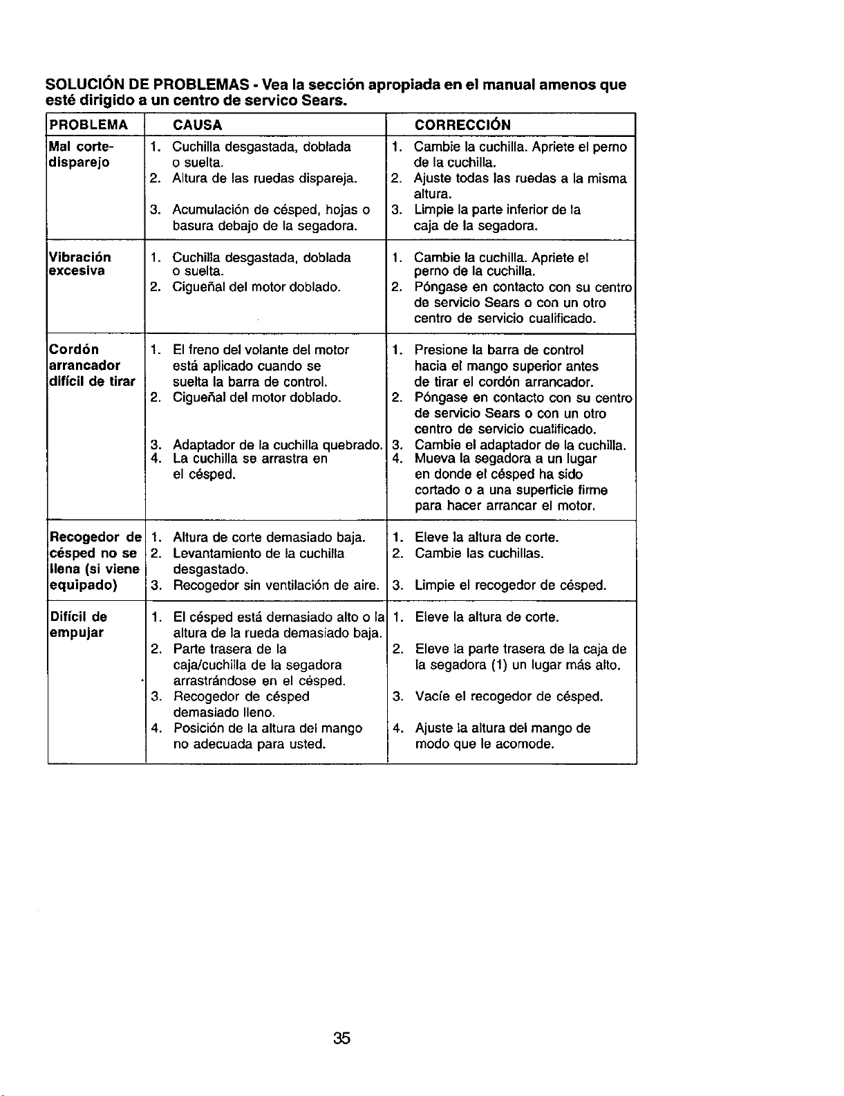
SOLUCION DE PROBLEMAS - Vea la secci6n apropiada en el manual amenos que
est6 dirigido a un centro de servico Sears.
PROBLEMA CAUSA CORRECCI(_N
Mal code- 1. Cuchilla desgastada, doblada 1. Cambie la cuchilla. Apriete el perno
disparejo o suelta, de la cuchilla.
2. Altura de las ruedas dispareja. 12. Ajuste todas las ruedas a la misma
altura.
3. Acumulaci6n de c_sped, hojas o 3. Limpie la parle inferior de la
basura debajo de la segadora, caja de la segadora.
Vibraci6n 1. Cuchilla desgastada, doblada 1. Cambie la cuchilla. Apriete el
excesiva o suelta, pemo de la cuchilla.
2. Ciguefial del motor doblado. 2. P6ngase en contacto con su centro
de servicio Sears o con un otro
centro de servicio cualificado.
Cord6n
arrancador
diffcil de tirar
Recogedor de
¢6sped no se
Ilena (si viene
aquipado)
Dificil de
_mpujar
1. El freno del volante del motor
esta aplicado cuando se
suelta la barra de control.
2. Ciguefial del motor doblado.
3. Adaptador de la cuchillaquebrado.
4. La cuchilla se arrastra en
el c_sped.
1. Altura de corte demasiado baja.
2. Levantamiento de la cuchilla
desgastado.
3. Recogedor sin ventilaci6n de aire.
1. El c_sped esff, demasiado alto o la
altura de la rueda demasiado baja.
2. Parle trasera de la
caja/cuchilla de la segadora
arrastrdndose en el cesped.
3. Recogedor de cdsped
demasiado Ileno.
4. Posici6n de la altura del mango
no adecuada para usted.
1. Presione la barra de control
hacia el mango superior antes
de tirar el cordbn arrancador.
2. P6ngase en contacto con su centro
de servicio Sears o con un otro
centro de servicio cualificado.
3. Cambie el adaptador de la cuchilla.
4. Mueva la segadora a un lugar
en donde el cSsped ha sido
cortado o a una superficie firme
para hacer arrancar el motor.
1.
2.
3.
1.
2.
3,
4.
Eleve la altura de code.
Cambie las cuchillas.
Limpie el recogedor de cdsped.
Eteve la altura de code.
Eleve la parte trasera de la caja de
la segadora (1) un lugar mds alto.
Vac{e el recogedor de c_sped.
Ajuste ta altura del mango de
modo que le acomode.
35
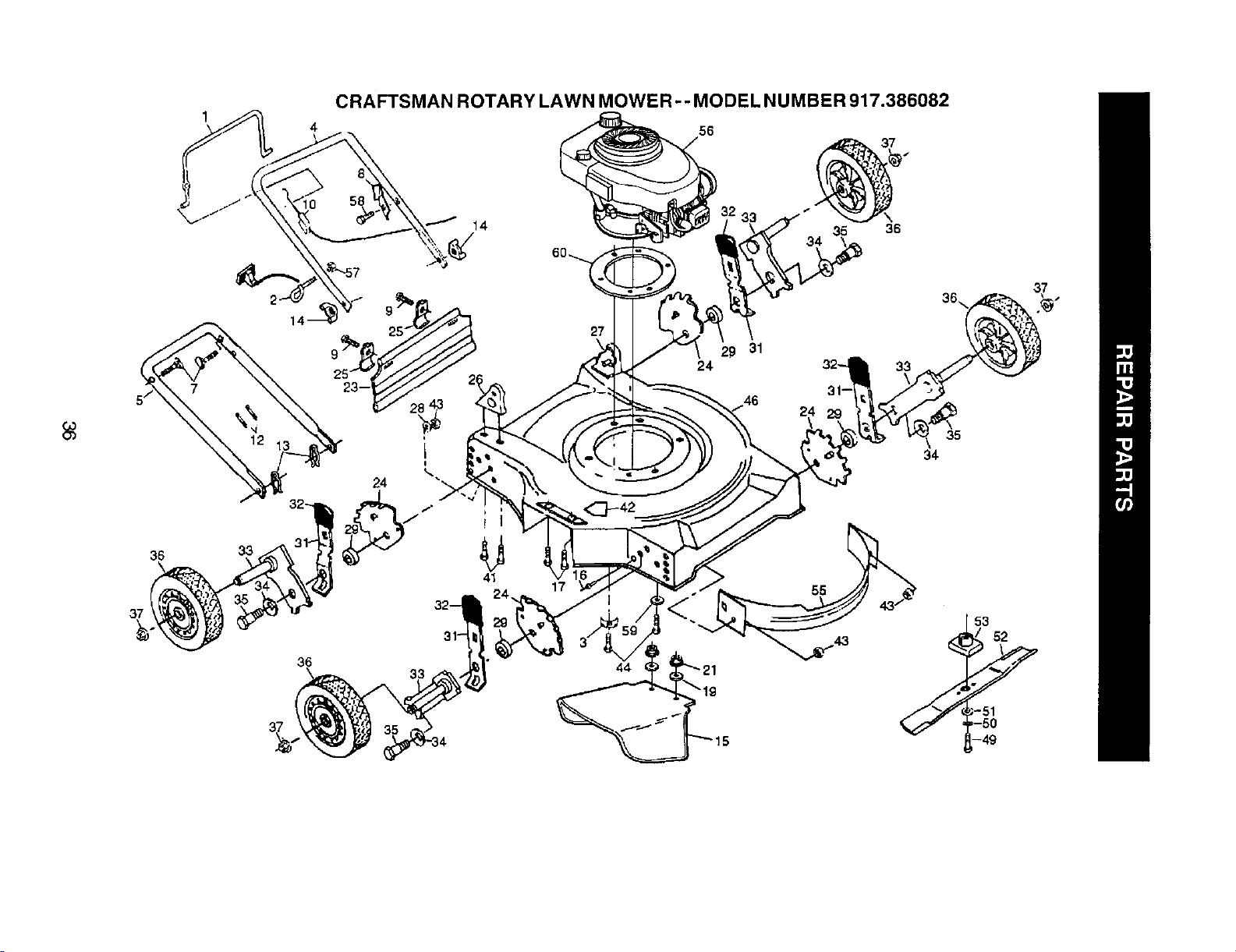
36
37
33
4
CRAFTSMAN ROTARY LAWN MOWER -- MODEL NUMBER 917.386082
56
35 36
34
41
17
-_9 31
24
24
55
36\
35
34
36
44
37
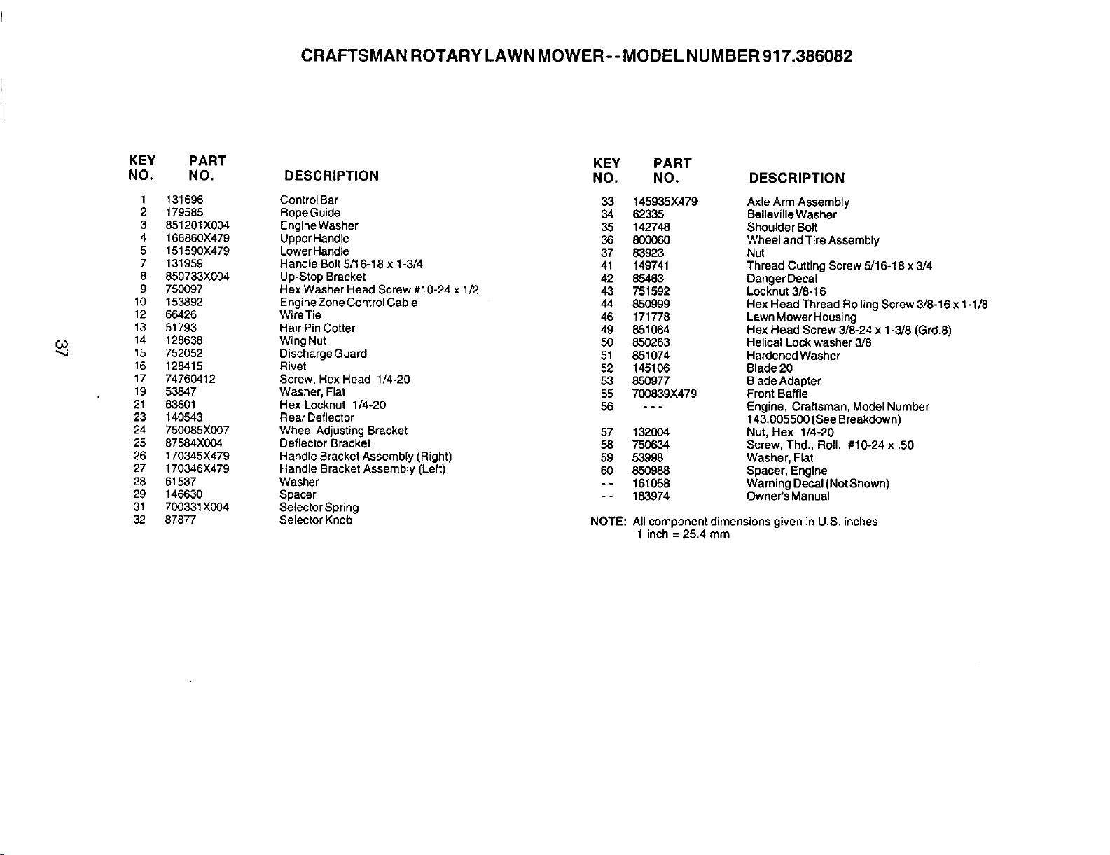
CRAFTSMAN ROTARY LAWN MOWER-- MODEL NUMBER 917.386082
KEY PART
NO. NO.
1 131696
2 179585
3 851201X004
4 166860X479
5 151590X479
7 131959
8 850733X004
9 750097
10 153892
12 66426
13 51793
14 128638
'_ 15 752052
16 128415
17 74760412
19 53847
21 63601
23 140543
24 750085X007
25 87584X004
26 170345X479
27 170346X479
28 61537
29 146630
31 700331X004
32 87877
KEY PART
DESCRIPTION NO. NO. DESCRIPTION
ControlBar 33 145935X479
RopeGuide 34 62335
Engine Washer 35 142748
UpperHandle 36 800060
LowerHandle 37 83923
Handle Bolt 5/16-18 x 1-3/4 41 149741
Up-Stop Bracket 42 85463
Hex Washer Head Screw #10-24 x 1/2 43 751592
Engine ZoneControl Cable 44 850999
WireTie 46 171778
Hair PinCotter 49 851084
WingNut 50 850263
Discharge Guard 51 851074
Rivet 52 145106
Screw, Hex Head 1/4-20 53 850977
Washer, Flat 55 700839X479
Hex Locknut 1/4-20 56 - - -
Rear Deflector
Wheel Adjusting Bracket 57 132004
Deflector Bracket 58 750634
Handle Bracket Assembly (Right) 59 53998
Handle Bracket Assembly (Left) 60 850988
Washer - - 161058
Spacer - - 183974
Selector Spring
Selector Knob
Axle Arm Assembly
BellevilleWasher
Shoulder Bolt
Wheel and Tire Assembly
Nut
Thread Cutting Screw 5/16-18 x 3/4
Danger Decal
Locknut 3/8-16
Hex Head Thread Rolling Screw 3/8-16 x 1-1/8
Lawn Mower Housing
Hex Head Screw 3/8-24 x 1-3/8 (Grd.8)
Helical Lock washer 3/8
Hardened Washer
Blade 20
BladeAdapter
Front Baffle
Engine, Craftsman,Model Number
143.005500 (See Breakdown)
Nut, Hex 1/4-20
Screw, Thd., Roll. #10-24 x .50
Washer, Flat
Spacer, Engine
Warning Decal (Not Shown)
Owner's Manual
NOTE: All component dimensions given in U,S. inches
1inch = 25.4 mm

CRAFTSMAN 4-CYCLE ENGINE MODEL NUMBER 143.005500
161
157
1537
224 2O7
43
48
223A
:38
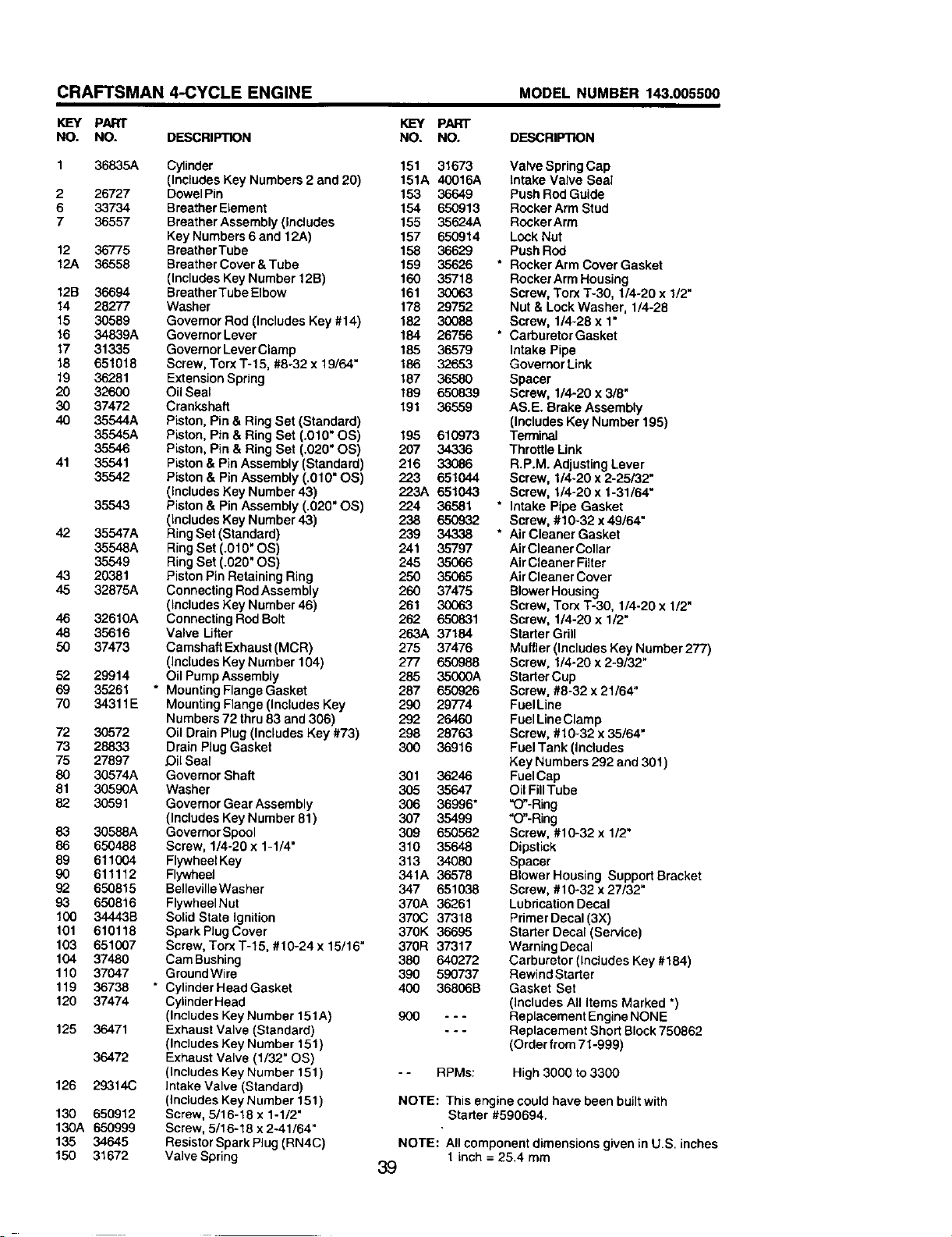
CRAFTSMAN 4-CYCLE ENGINE MODEL NUMBER 143.005500
KEY PART
NO. NO. DESCRIPTION
1 36835A Cylinder
(IncludesKey Numbers2 and 20)
2 26727 DowelPin
6 33734 BreatherElement
7 36557 BreatherAssembly(Includes
KeyNumbers6 and 12A)
12 36775 BraatherTube
12A 36558 BreatherCover&Tube
(Includes KeyNumber 12B)
12B 36694 BreatherTubeElbow
14 28277 Washer
15 30589 Governor Rod (IncludesKey#14)
16 34839A GovernorLever
17 31335 GovernorLeverClamp
18 651018 Screw, TorxT-15, #8-32 x 19/64"
19 36281 ExtensionSpring
20 32600 OilSeal
30 37472 Crankshaft
40 35544A Piston, Pin & Ring Set (Standard)
35545A Piston, Pin& RingSet (.010" OS)
35546 Piston, Pin & RingSet (.020" OS)
41 35541 Piston& Pin Assembly(Standard)
35542 Piston& Pin Assembly (.010" OS)
(includesKey Number 43)
35543 Piston& Pin Assembly (.020" OS)
(IncludesKey Number 43)
42 35547A RingSet (Standard)
35548A RingSet (.010" OS)
35549 RingSet (.020" OS)
43 20381 Piston PinRetaining Ring
45 32875A Connecting RodAssembly
(Includes Key Number 46)
46 32610A Connecting Rod Solt
48 35616 Valve Lifter
50 37473 Camshaft Exhaust (MCR)
(Includes Key Number 104)
52 29914 Oil Pump Assembly
69 35261 * Mounting Flange Gasket
70 34311E MountingFlange (IncludesKey
Numbers 72 thru63 and 306)
72 30572 Oil Drain Plug (Includes Key #73)
73 28833 Drain Plug Gasket
75 27897 JOilSeal
80 30574A Governor Shaft
81 30590A Washer
82 30591 Governor Gear Assembly
(Includes Key Number 81)
83 30588A Governor Spool
86 650488 Screw, 1/4-20 x 1-1/4"
89 611004 Flywheel Key
90 611112 Flywheel
92 650815 Belleville Washer
93 650816 Flywheel Nut
100 34443B Solid State ignition
101 610118 Spark Plug Cover
103 651007 Screw, Torx T-15, #10-24 x 15/16"
104 37480 Cam Bushing
110 37047 Ground Wire
119 36738 * CylinderHeadGasket
120 37474 Cylinder Head
(Includes Key Number 151A)
125 36471 Exhaust Valve (Standard)
(Includes Key Number 151)
36472 Exhaust Valve (1/32" OS)
(Includes Key Number 151)
126 29314C Intake Valve (Standard)
(includes Key Number 151)
130 650912 Screw, 5/16-18 x 1-1/2"
130A 650999 Screw, 5/16-18 x 2-41/64"
135 34645 ResistorSparkPiug (RN4C)
150 31672 Valve Spring
I<L=Y PART
NO. NO. DESCRIPTION
151 31673 Valve SpringCap
151A 40016A Intake Valve Seal
153 36649 Push RodGuide
154 650913 RockerArm Stud
155 35624A RockerArm
157 650914 LockNut
158 36629 PushRod
159 35626 * RockerArmCoverGasket
160 35718 RockerArm Housing
161 30063 Screw, Tor-xT-30, 1/4-20 x 1/2"
178 29752 Nut & LockWasher, 1/4-28
182 30088 Screw, 1/4-28 x 1"
184 26756 * CarburetorGasket
185 36579 Intake Pipe
186 32653 GovernorLink
187 36580 Spacer
189 650839 Screw, 1/4-20 x 3/8"
191 36559 AS.E. Brake Assembly
(Includes Key Number 195)
195 610973 Terminal
207 34336 ThrottleLink
216 33086 R+P.M AdjustingLever
223 651044 Screw, 1/4-20 x 2-25/32"
223A 651043 Screw, 114-20x 1-31/64"
224 36581 * Intake Pipe Gasket
238 650932 Screw, #10-32 x 49/64"
239 34338 * AirCleanerGasket
241 35797 Air Cleaner Collar
245 35066 Air Cleaner Filter
250 35065 Air Cleaner Cover
260 37475 Blower Housing
261 30063 Screw, Torx 1"-30, 1/4-20 x 1/2"
262 650831 Screw, 1/4-20 x 1/2"
263A 37184 Starter Grill
275 37478 Muffler(Includes Key Number 277)
277 650988 Screw, 1/4-20 x 2-9/32"
285 35000A Starter Cup
287 650926 Screw, #8-32 x 21/64"
290 29774 FuelLine
292 26460 FuelLine Clamp
298 26763 Screw, #10-32 x 35/64"
300 36916 FuelTank (Includes
Key Numbers 292 and 30t)
301 36246 FuelCap
305 35647 Oil FillTube
306 36996" "O"-Ring
307 35499 "O"-Ring
309 650562 Screw, #10-32x 1/2"
310 35648 Dipstick
313 34080 Spacer
341A 36578 Blower Housing Support Bracket
347 651038 Screw, #10-32 x 27/32"
370A 36261 Lubrication Decal
370C 37318 Primer Decal (3X)
370K 36695 Starter Decal (Service)
370R 37317 Warning Decal
380 640272 Carburetor (Includes Key #164)
390 590737 Rewind Starter
400 36806B Gasket Set
(Includes All Items Marked ")
g00 - - - Replacement Engine NONE
- - - Replacement Short Block 750862
(Order from 71-999)
- - RPMs: High 3000 to 3300
NOTE: This engine could have been built with
Starter #590694.
NOTE: All componentdimensions giveninU.S. inches
1 inch = 25.4 mm
39
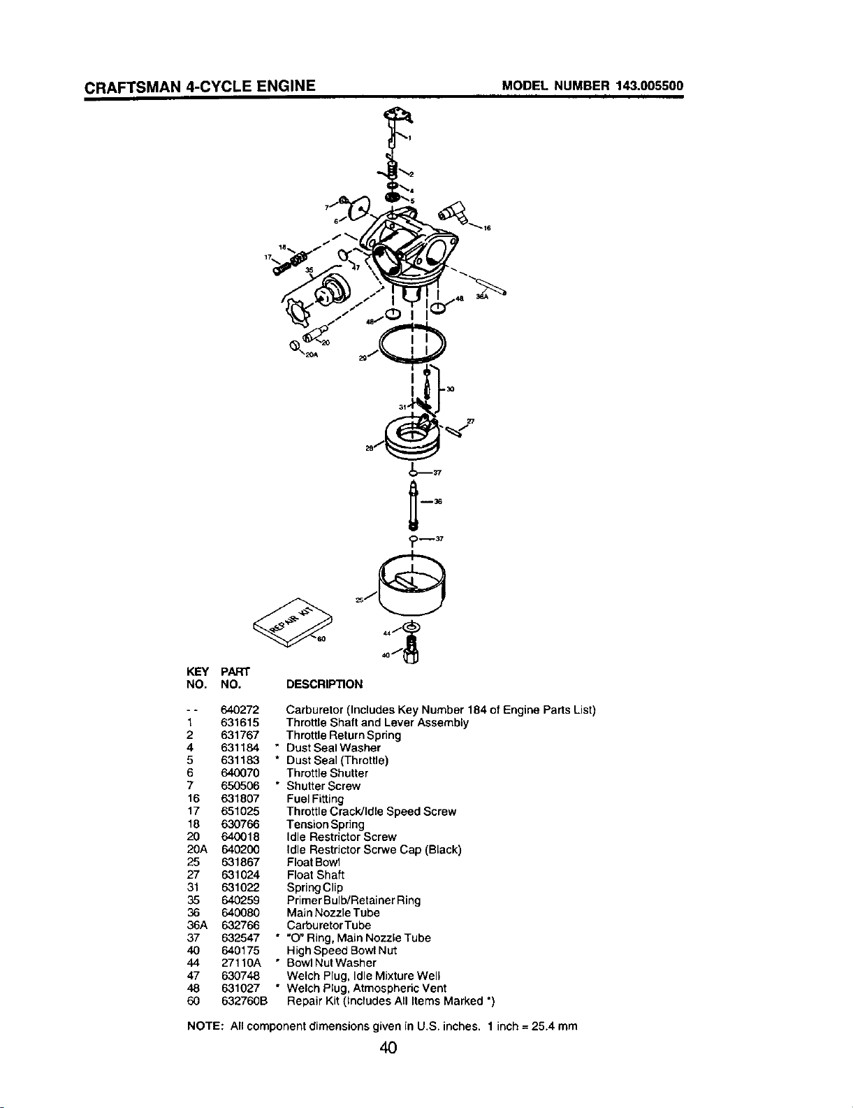
CRAFTSMAN 4-CYCLE ENGINE MODEL NUMBER 143.005500
KEY
NO.
PART
NO. DESCRIPTION
- - 640272
1 631615
2 631767
4 631184 *
5 631183 *
6 640070
7 650506 "
16 631807
17 651025
18 630766
20 640018
20A 640200
25 631867
27 631024
31 631022
35 640259
36 640080
36A 632766
37 632547 "
40 640175
44 27110A *
47 630748
48 631027 *
60 632760B
Carburetor (Includes Key Number 184 of Engine Parts List)
Throttle Shaft and Lever Assembly
Throttle Return Spring
Dust Seal Washer
Dust Seal (Throttle)
Throttle Shutter
Shutter Screw
Fuel Fitting
Throttle Crack/Idle Speed Screw
Tension Spring
Idle Restrictor Screw
Idle Restrictor Scrwe Cap (Black)
Float Bowl
Float Shaft
Spring Clip
Primer Bulb/Retainer Ring
Main Nozzle Tube
CarburetorTube
"O" Ring, Main Nozzle Tube
High Speed Bowl Nut
Bowl Nut Washer
Welch Plug, Idle Mixture Well
Welch Plug, Atmospheric Vent
Repair Kit (Includes All Items Marked *)
NOTE: All component dimensions given in U.S. inches. 1 inch = 25.4 mm
4O
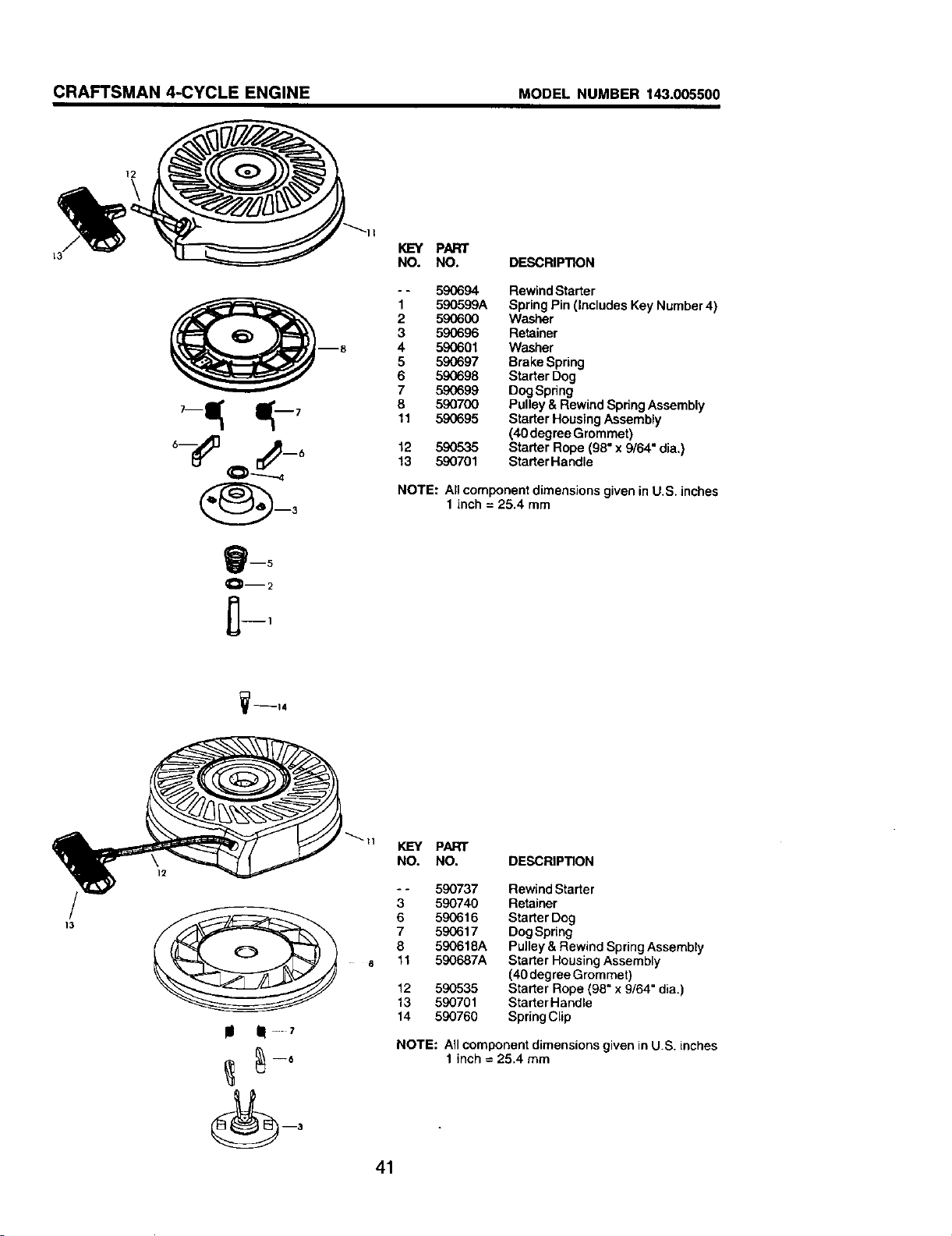
CRAFTSMAN 4-CYCLE ENGINE MODEL NUMBER 143.005500
B
KEY PART
NO. NO. DESCRIPTION
- - 590694 Rewind Starter
1 590599A Spring Pin(Includes Key Number4)
2 59(3600 Washer
3 590696 Retainer
4 590601 Washer
5 590697 Brake Spring
6 590698 Starter Dog
7 590699 DogSpdng
8 590700 Pulley & Rewind Spring Assembly
11 590695 Starter Housing Assembly
(40degree Grommet)
12 590535 Starter Rope (98" x 9/64" dia.)
13 590701 Starter Handle
NOTE: All componentdimensions given in U.S. inches
1 inch = 25.4 mm
1_--14
KEY PART
NO. NO. DESCRIPTION
- - 590737 Rewind Starter
3 590740 Retainer
6 590616 Starter Dog
7 590617 Dog Spring
8 590618A Pulley & Rewind Spring Assembty
11 5_K)687A Starter Housing Assembly
(40 degree Grommet)
12 590535 Starter Rope (98" x 9/64" dia.)
13 590701 Starter Handle
14 590760 Spdng Clip
NOTE: All component dimensions given in U.S. inches
1 inch = 25.4 mm
41

SERVICE NOTES
42

SERVICE NOTES
43

Your Home
For repair - in your home - of all major brand appliances,
lawn and garden equipment, or heating and cooling systems,
no matter who made it, no matter who sold it!
For the replacement parts, accessories and
owner's manuals that you need to do-it-yourself.
For Sears professional installation of home appliances
and items like garage door openers and water heaters.
1-800-4-MY-HOME _ Anytime, dayor night
(1-800-469-4663) (U.S.A. and Canada)
www.sears,com www.sears.ca
OurHome
For repair of carry-in products like vacuums, lawn equipment,
and electronics, call or go on-line for the nearest
Sears Parts and Repair Center.
1-800-488-1222 Anytime, day or night (U.S.A. only)
www.sears.com
To purchase a protection agreement on a product serviced by Sears:
1-800-827-6655 (u.s._) 1-800-361-6665 (Canada)
Para pedir servicio de reparaciSn
a domicilio, y para ordenar pieT_s:
1-888-SU-HOGAFI sM
(1-888-784-6427)
Au Canada pour service en franc_,.ais: _
1-800-LE-FOYER Mc
(_-_oo-533-6937)
www.sears.ca ...._.__
AR,N
© Seats,RoebuckandCo.
® Registered Trademark / _u Trademark / SM Service Mark of Sears, Roebuck and Co.
de F_,bnca / Marca de Serv_e o de Sears, Roebuck and Co.
® Marca Registrada / TM Marca sM • •
MCMarque de commerce / uo Marque deposee de Sears, Roebuck and Co.
183974 06.11.02 BY Printed in U.S.A.