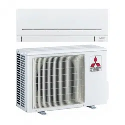
User Gudie Mitsubishi MSZ-GE12NA Air conditioner
INSTALLATION OF DPLS1
- Disconnect (and lock-out, if required) all power to the Mr. Slim or CITY MULTI Indoor Unit at the Disconnect Switch (if installed) or at the main disconnect panel serving the indoor and/or outdoor unit.
- Connect DPLS1 Splice Connector to the selected mating Wire Harness Connector - see wiring harness selection above.
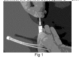
- Connect the Control Box’s Splice C__ onnector to the mating connector on the Wire Harness (Fig 1).
Typical Installation
- Remove front cover of indoor unit in order to expose the coil and the control circuit area of the unit (Fig 2). The disassembly of the front cover, air filters, and possibly electrical shields will vary according to style of indoor unit installed.

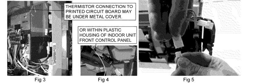
- Locate the corresponding connector (see Table 1) on the printed control circuit board and, remove the connector of the thermistor (Fig 4).
- Plug female connector of the Wire Harness into the printed circuit board, and plug the male connector on the opposite end into the thermistor connector
- Determine the best location for the DPLS1 Control Box: Using the double-sided tape, mount the Control Box in a location inside the indoor unit that will allow clearance for the cover to be reassembled (Fig 6).
- MOUNT CONTROL BOX IN AN AREA WHERE THE FRONT COVER WILL NOT INTERFERE |WHEN REASSEMBLED. Fig 6 Reassemble any covers that were removed during the installation. Test the DPLS1: Reconnect power to the indoor unit.
- Use extreme caution, the DPLS1 is a low voltage device however; do not make contact with any high voltages on the indoor unit during testing.
- Turn unit on and set cooling thermostat to lowest temperature setting. Make sure to restore power to the outdoor unit before performing the test in step
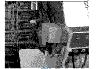
- Using a screwdriver or other metallic object, carefully make a connection between the two pins on the Water Sensor (Fig 7). Indoor unit should shut down after a short delay.
- Disconnect indoor unit power before proceeding to the next step.
- Determine the best location for the DPLS1 Water Sensor. Make sure that power has been disconnected. Find the drain pan below the coil in the indoor unit.
- It is located directly below the aluminum fins of the coil and is slightly wider than the coil depending on the style of indoor unit.
Wipe all water, dirt and dust from the drain pan with a damp cloth. DO NOT REMOVE DOUBLE SIDED TAPE ON WATER
SENSOR YET. Temporarily locate the Water Sensor in the drain pan.
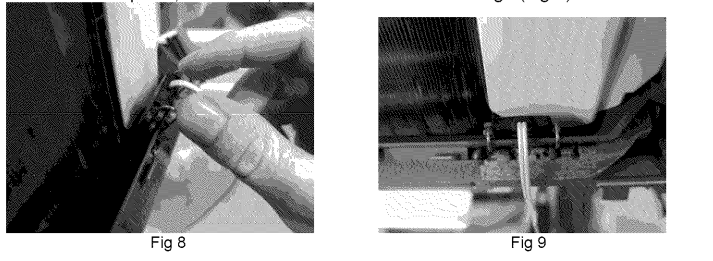
Rotate the panel clips on the Water Sensor so that the clips are towards the front of the indoor unit and slide onto the front edge of the drain pan (Fig 8). Push the panel clips all the way down onto the plastic drain pan then push the Water Sensor down until it stops on, or close to, the bottom of the drain trough (Fig 9)*.
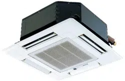
Temporarily reassemble the front cover of the indoor unit to make sure that it reattaches properly. If there is interference with the front cover, relocate the Water Sensor on the drain pan and recheck clearances. Once the best location has been determined, remove the double-sided tape on the Water Sensor and reinstall it in the same manner as described above. Ensure the Water Sensor touches the bottom of the trough and the panel clips are pushed all the way down on the front edge of the trough (Fig 10). *These installation instructions are typical for all wall mounted, floor standing, ceiling recessed, ceiling concealed, and ceiling suspended units. Location of the water sensor should at the drain pan no less than 3/8” from the bottom
BATTERY INSTALLATION on the DPLS1:
- Remove #2 screw from the top of the DPLS1 control box

- Fig 11 2. Separate the top from the base of the contro! box. Remove the 1/2 AA Lithium battery and replace with a new battery of identical type, making sure that battery polarity is correct (fig 12).

LIMITED WARRANTY
- ONE YEAR DRAIN PAN LEVEL SENSOR/CONTROL WARRANTY - MITSUBISHI ELECTRIC
- ELECTRONICS USA, INC. (‘MEUS”) warrants to the original end-user of this Drain Pan Level Sensor/Control that, should it prove defective due to improper workmanship and/or material under normal use and proper installation for a period of one year from the date of installation, we will repair or replace, at our option, any defective Drain Pan Level Sensor/Control or component without charge for the part. Replacement Drain Pan Level Sensor/Controls is warranted for the remainder of the original warranty period.
- THIS WARRANTY DOES NOT INCLUDE LABOR or other costs incurred for servicing, repairing, removing, installing, shipping or handling of defective or replacement Drain Pan Level Sensor/Control.
- TO OBTAIN WARRANTY SERVICE, please contact your dealer or contractor who installed this product. If your dealer or contractor needs assistance, its distributor is available for consultation. Should you not receive satisfactory warranty service, please call, fax or write This limited warranty applies only while the Drain Pan Level Sensor/Control remains at the site of the original installation.
- This limited warranty applies only if the Drain Pan Level Sensor/Control is installed and operated in accordance with the manufacturer’s instructions and in compliance with applicable local installation and building codes and good trade practices.