Ser,
TM
oY
DIAMONDBACK”
Biges
Drain
Panel
Level
Sensor/Control
Installation
Instructions
The
DPLS1
Drain
Pan
Level
Sensor
/
Control
provides
protection
against
drain
pan
overflow
in
Mitsubishi
Electric
Mr.
Slim
and
CITY
MULTI
Indoor
Units.
The
unit
will
sense
a
high
condensate
level
in
the
drain
pan.
Should
this
occur
the
control
shuts
down
the
indoor
unit
before
an
overflow
can
occur.
A
thermistor
error
code
will
be
produced
should
the
DPLS1
activate
indicating
a
fault
which
must
be
resolved
before
the
unit
will
re-start.
This
unit
provides
electronic
overflow
protection
for
Drain
Pans
in
all
Mr.
Slim
and
CITY
MULTI
indoor
units:
MFZ,
MS,
MSY/Z,
SEZ,
SLZ,
PCA/PCFY,
PDFY,
PEA/PEAD/PEFY,
PKA/PKFY,
PLA,
PLKA/PLFY,
PMFY,
and
PVFY.
Meets
requirements
as
listed
alternative
to
secondary
drain
pans
in
all
indoor
unit
installations
covered
by
the
International
Mechanical
Code
and
adaptations.
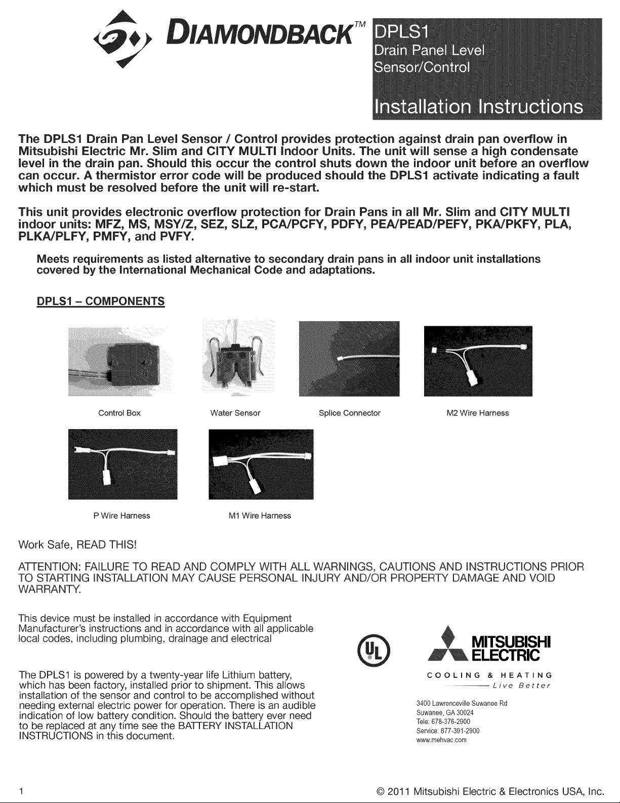
DPLS1-—
COMPONENTS
Control
Box
Water Sensor
Splice
Connector
M2
Wire
Harness
=
P
Wire
Harness
M1
Wire
Harness
Work
Safe,
READ
THIS!
ATTENTION:
FAILURE
TO
READ
AND
COMPLY
WITH
ALL
WARNINGS,
CAUTIONS
AND
INSTRUCTIONS
PRIOR
TO
STARTING
INSTALLATION
MAY
CAUSE
PERSONAL
INJURY
AND/OR
PROPERTY
DAMAGE
AND
VOID
WARRANTY.
This
device
must
be
installed
in
accordance
with
Equipment
Manufacturer’s
instructions
and
in
accordance
with
all
applicable
local
codes,
including
plumbing,
drainage
and
electrical
U
MITSUBISHI
¥L
ELECTRIC
The
DPLS1
is
powered
by
a
twenty-year
life
Lithium
battery,
COOLING
&
HEATING
which
has
been
factory,
installed
prior
to
shipment.
This
allows
wee
Live
Better
installation
of
the
sensor
and
control
to
be
accomplished
without
/
needing
external
electric
power
for
operation.
There
is
an
audible
3400
Lawrenceville
Suwanee
Re
indication
of
low
battery
condition.
Should
the
battery
ever
need
ane
oo
to
be
replaced
at
any
time see
the
BATTERY
INSTALLATION
Servioe:
877.301.2900
INSTRUCTIONS
in
this
document.
”
www.mehvac.com
©
2011
Mitsubishi
Electric
&
Electronics
USA,
Inc.
ae,
mm
DPLS1
Drain
Panel
Level
Sensor/Control
GA
&
Di
A
MONDBACK
Protected
under
one
or
more
patents
©
2011
Mitsubishi
Electric
&
Electronics
USA,
Inc.
ee
eee
eee
eee
eee
ee
eee
eee
ee,
Connector
to
Control
Box
M2
Wire
MS
MSZ/Y
2
pin,
female
connector
(with
black
2
pin,
male
connector
to:
2
pin.
male
connector
Harness
MFZ
heat
shrink)
to
CN111
RT11
(Room
Temp.
Thermistor)
pin,
PKA
PCA
2
pin,
male
connector
to:
oe
PLA
2
pin,
female
connector
to
CN20
TH1
(Room
Temp.
Thermistor)
SLZ
2
pin,
male
connector
to:
na
PKFY-PNBMU-E
TH1
(Room
Temp.
Thermistor)
or
2
pin,
male
connector
PLFY-P**NCMU-E
2
pin,
female
connector
to
CN20,
.
CN21
or
CN29
TH22
(Pipe
Temp.
PMFY-P*NBMU-E
Thermistor/Liquid)
or
PVFY-P"EOOA
TH23
(Pipe
Temp
PEFY-P“*NMHU-E
Thermistor/Gas)
PLA
PKA
PCA
4
pin,
male
connector
to
PEA(D)
SEZ
.
TH2
(Pipe
Temp.
PKFY-P*'NH/
4
pin,
female
connector
to
CN44
Thermistor/Liquid)
and
KMU-E
PLFY-P*NBMU-E
TH5
(Pipe
Temp.
Thermistor/Gas)
PCFY-P**NKMU-E
PEFY-P**NMS/AU-E
M1
Wire
Ms
4
pin,
male
connector
to
2
pi
|
i
Harness
RT12
(Coil
Temp.
Thermistor)
pin,
male
CONNECIOF
4
pin,
male
connector
to
4
pin,
female
connector
to
CN112
. .
RT12
(Coil
Temp.
Thermistor
-
MSZ/Y
Main)
and
RT13
(Coil
Temp.
Thermistor
-
Sub)
4
pin,
male
connector
to
MFZ
4
pin,
female
connector
to
CN113
AT15
(Coil
Temp.
Thermistor)
INSTALLATION
OF
DPLS1
Drain
Pan
Level
Sensor/Control:
(To
ensure
proper
performance
of
product,
instructions
must
be
followed.)
1.
Disconnect
(and
lock-out,
if
required)
all
power
to
the
Mr.
Slim
or
CITY
MULTI
Indoor
Unit
at
the
Disconnect
Switch
(if
installed)
or
at
the
main
disconnect
panel
serving
the
indoor
and/or
outdoor
unit.
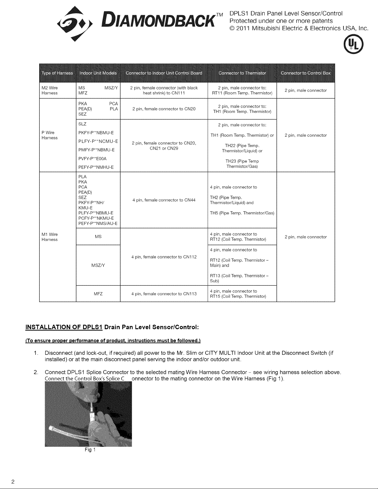
2.
Connect
DPLS1
Splice
Connector
to
the
selected
mating
Wire
Harness
Connector
-
see
wiring
harness
selection
above.
Connect
the
Control
Box’s
Splice
C__
onnector
to
the
mating
connector
on
the
Wire
Harness
(Fig
1).
Fig
1
ae,
mm
DPLS1
Drain
Panel
Level
Sensor/Control
GA
&
Di
A
MONDBACK
Protected
under
one
or
more
patents
©
2011
Mitsubishi
Electric
&
Electronics
USA,
Inc.
UL
®
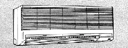
Typical
Installation
-
example:
Wall
Mount
Indoor
Unit
-
MS/MSY/MSZ/PKA/PKFY:
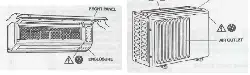
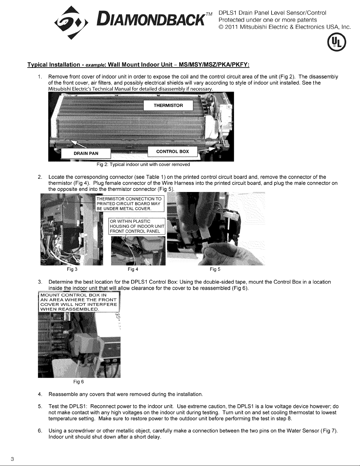
1.
2.
3.
Remove
front
cover
of
indoor
unit
in
order
to
expose
the
coil
and
the
control
circuit
area
of
the
unit
(Fig
2).
The
disassembly
of
the
front
cover,
air
filters,
and
possibly
electrical
shields
will
vary
according
to
style
of
indoor
unit
installed.
See
the
Mitsubishi
Electric's
Technical
Manual
for
detailed
disassembly
if
necessary.
THERMISTOR
RAIN
PAN
9
«CONTROL
BOX
sf
Fig
2:
Typical
indoor
unit
with
cover
removed
Locate
the
corresponding
connector
(see
Table
1)
on
the
printed control
circuit
board
and,
remove
the
connector
of
the
thermistor
(Fig
4).
Plug
female
connector
of
the
Wire
Harness
into
the
printed
circuit
board,
and
plug
the
male
connector
on
the
opposite
end
into
the
thermistor
connector
(Fig
5).
THERMISTOR
CONNECTION
TO
PRINTED
CIRCUIT
BOARD
MAY
BE
UNDER
METAL
COVER.
OR
WITHIN
PLASTIC
j
HOUSING
OF
INDOOR
UNIT
FRONT
CONTROL
PANEL
Fig
3
Fig
4
Fig
5
Determine
the
best
location
for
the
DPLS1
Control
Box:
Using
the
double-sided
tape,
mount
the
Control
Box
in
a
location
inside
the
indoor
unit
that
will
allow
clearance
for
the
cover
to
be
reassembled
(Fig
6).
MOUNT
CONTROL
BOX
IN
AN
AREA
WHERE
THE
FRONT
COVER
WILL
NOT
INTERFERE
|WHEN
REASSEMBLED.
Fig
6
Reassemble
any
covers
that
were
removed
during
the
installation.
Test
the
DPLS1:
Reconnect
power
to
the
indoor
unit.
Use
extreme
caution,
the
DPLS1
is
a
low
voltage
device
however;
do
not
make
contact
with
any
high
voltages
on
the
indoor
unit
during
testing.
Turn
unit
on
and
set
cooling
thermostat
to
lowest
temperature
setting.
Make
sure
to
restore
power
to
the
outdoor
unit
before
performing
the
test
in
step
8.
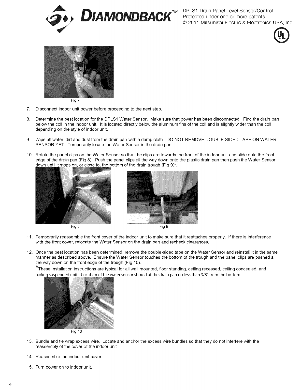
Using
a
screwdriver
or
other
metallic
object,
carefully
make
a
connection
between
the
two
pins
on
the
Water
Sensor
(Fig
7).
Indoor
unit
should
shut
down
after
a
short
delay.
10.
11.
12.
13.
14.
15.
ae,
mm
DPLS1
Drain
Panel
Level
Sensor/Control
GA
&
Di
A
MONDBACK
Protected
under
one
or
more
patents
©
2011
Mitsubishi
Electric
&
Electronics
USA,
Inc.
UL
®
Fig
7
Disconnect
indoor
unit
power
before
proceeding
to
the
next
step.
Determine
the
best
location
for
the
DPLS1
Water
Sensor.
Make
sure
that
power
has
been
disconnected.
Find
the
drain
pan
below
the
coil
in
the
indoor
unit.
It
is
located
directly
below
the
aluminum
fins
of
the
coil
and
is
slightly
wider
than
the
coil
depending
on
the
style
of
indoor
unit.
Wipe
all
water,
dirt
and
dust
from
the
drain
pan
with
a
damp
cloth.
DO
NOT
REMOVE
DOUBLE
SIDED
TAPE
ON
WATER
SENSOR
YET.
Temporarily
locate
the
Water
Sensor
in
the
drain
pan.
Rotate
the
panel
clips
on
the
Water
Sensor
so
that
the
clips
are
towards
the
front
of
the
indoor
unit
and
slide
onto
the
front
edge
of
the
drain
pan
(Fig
8).
Push
the
panel
clips
all
the
way
down
onto
the
plastic
drain
pan
then
push
the
Water
Sensor
down
until
it
stops
on,
or
close
to,
the
bottom
of
the
drain
trough
(Fig
9)*.
Fig
8
Fig
9
Temporarily
reassemble
the
front
cover
of
the
indoor
unit
to
make
sure
that
it
reattaches
properly.
If
there
is
interference
with
the
front
cover,
relocate
the
Water
Sensor
on
the
drain
pan and
recheck
clearances.
Once
the
best
location
has
been
determined,
remove
the
double-sided
tape
on
the
Water
Sensor
and
reinstall
it
in
the
same
manner
as
described
above.
Ensure
the
Water
Sensor
touches
the
bottom
of
the
trough
and
the
panel
clips
are
pushed
all
the
way
down
on
the
front
edge
of
the
trough
(Fig
10).
*These
installation
instructions
are
typical
for
all
wall
mounted,
floor
standing,
ceiling
recessed,
ceiling
concealed,
and
ceiling
suspended
units.
Location
of
the
water
sensor
should
at
the
drain
pan
no
less
than
3/8”
from
the
bottom
ig
4
Bundle
and
tie
wrap
excess
wire.
Locate
and
anchor
the
excess
wire
bundles
so
that
they
do
not
interfere
with
the
reassembly
of
the
cover
of
the
indoor
unit.
Reassemble
the
indoor
unit
cover.
Turn
power
on
to
indoor
unit.
ae,
mm
DPLS1
Drain
Panel
Level
Sensor/Control
GA
&
Di
A
MONDBACK
Protected
under
one
or
more
patents
©
2011
Mitsubishi
Electric
&
Electronics
USA,
Inc.
UL
®
BATTERY
INSTALLATION
on
the
DPLS1:
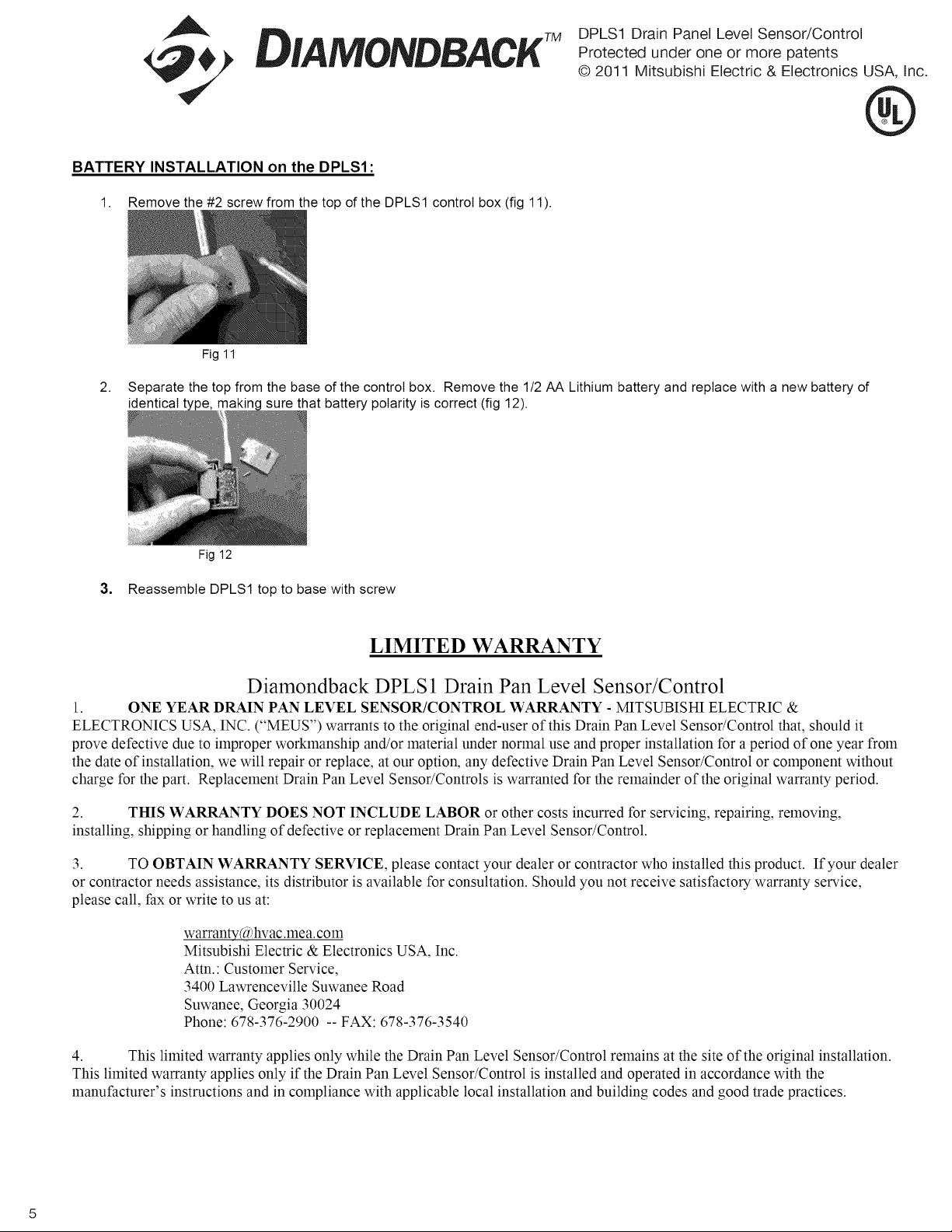
1.
Remove
#2
screw
from
the top
of
the
DPLS1
control
box
(fig
11).
Fig
11
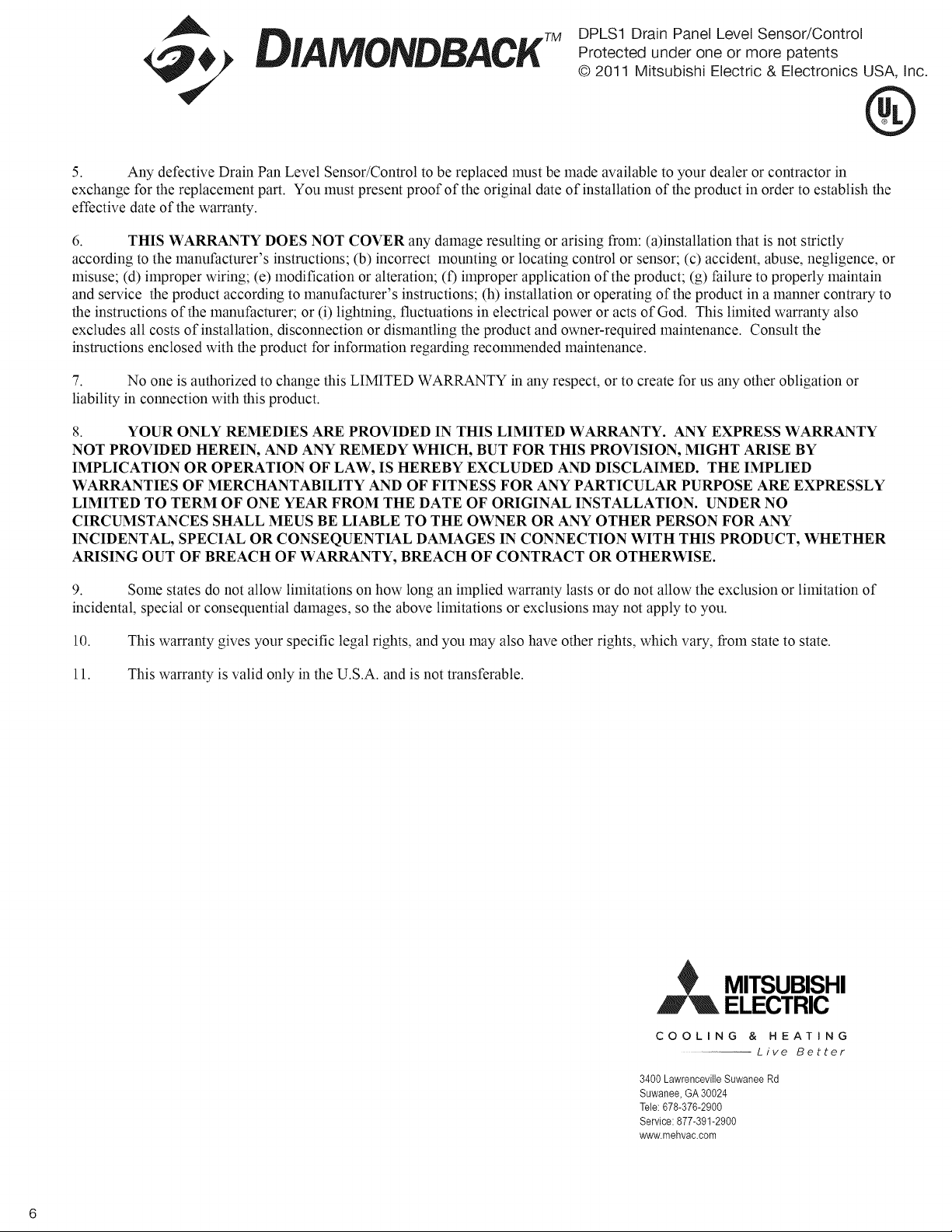
2.
Separate
the top
from
the
base
of
the
contro!
box.
Remove
the
1/2
AA
Lithium
battery
and
replace
with
a
new
battery
of
identical
type,
making
sure
that
battery
polarity
is
correct
(fig
12).
Fig
12
3.
Reassemble
DPLS1
top
to
base
with
screw
LIMITED
WARRANTY
Diamondback DPLS1
Drain
Pan
Level
Sensor/Control
1.
ONE
YEAR
DRAIN
PAN
LEVEL
SENSOR/CONTROL
WARRANTY
-
MITSUBISHI
ELECTRIC
&
ELECTRONICS
USA,
INC.
(‘MEUS”)
warrants
to
the
original
end-user
of
this
Drain
Pan
Level
Sensor/Control
that,
should
it
prove
defective
due
to
improper
workmanship
and/or
material
under
normal
use
and
proper
installation
for
a
period
of
one
year
from
the
date
of
installation,
we
will
repair
or
replace,
at
our
option,
any
defective
Drain Pan
Level
Sensor/Control
or
component
without
charge
for
the part.
Replacement
Drain
Pan
Level
Sensor/Controls
is
warranted
for
the
remainder
of
the
original
warranty
period.
2,
THIS
WARRANTY
DOES NOT
INCLUDE
LABOR
or
other
costs
incurred
for
servicing,
repairing,
removing,
installing,
shipping
or
handling
of
defective
or
replacement
Drain
Pan Level
Sensor/Control.
3.
TO
OBTAIN
WARRANTY
SERVICE,
please
contact
your
dealer
or
contractor
who
installed
this
product.
If
your
dealer
or
contractor
needs
assistance,
its
distributor
is
available
for
consultation.
Should
you
not
receive
satisfactory
warranty
service,
please
call,
fax
or
write
to
us
at:
watranty(@hvac.mea.com
Mitsubishi
Electric
&
Electronics
USA,
Inc.
Attn.:
Customer
Service,
3400
Lawrenceville
Suwanee
Road
Suwanee,
Georgia
30024
Phone:
678-376-2900
--
FAX:
678-376-3540
4.
This
limited
warranty
applies
only
while
the
Drain
Pan
Level
Sensor/Control
remains
at
the
site
of
the
original
installation.
This
limited
warranty
applies
only
if
the
Drain
Pan Level
Sensor/Control
is
installed
and
operated
in
accordance
with
the
manufacturer’s
instructions
and
in
compliance
with
applicable
local
installation
and
building
codes
and
good
trade
practices.
ae,
mm
DPLS1
Drain
Panel
Level
Sensor/Control
GA
&
Di
A
MONDBACK
Protected
under
one
or
more
patents
©
2011
Mitsubishi
Electric
&
Electronics
USA,
Inc.
UL
®
5.
Any
defective
Drain
Pan
Level
Sensor/Control
to
be
replaced
must
be
made
available
to
your
dealer
or
contractor
in
exchange
for
the
replacement
part.
You
must
present
proof
of
the
original
date
of
installation
of
the
product
in
order
to
establish
the
effective
date
of
the
warranty.
6.
THIS
WARRANTY
DOES
NOT
COVER
any
damage
resulting
or
arising
from:
(a)installation
that
is
not
strictly
according
to
the
manufacturer’s
instructions;
(b)
incorrect
mounting
or
locating
control
or
sensor;
(c)
accident,
abuse,
negligence,
or
misuse;
(d)
improper
wiring;
(¢)
modification
or
alteration;
()
improper
application
of
the
product;
(g)
failure
to
properly
maintain
and
service
the
product
according
to
manufacturer’s
instructions;
(h)
installation
or
operating
of
the
product
in
a
manner
contrary
to
the
instructions
of
the
manufacturer;
or
(i)
lightning,
fluctuations
in
electrical
power
or
acts
of
God.
This
limited
warranty
also
excludes
all
costs
of
installation,
disconnection
or
dismantling
the
product
and
owner-required
maintenance.
Consult
the
instructions
enclosed
with
the
product
for
information
regarding
recommended
maintenance.
7.
No
one
is
authorized
to
change
this
LIMITED
WARRANTY
in
any
respect,
or
to
create
for
us
any
other
obligation
or
liability
in
connection
with
this
product.
8.
YOUR
ONLY
REMEDIES
ARE
PROVIDED
IN
THIS
LIMITED
WARRANTY.
ANY
EXPRESS
WARRANTY
NOT
PROVIDED
HEREIN,
AND
ANY
REMEDY
WHICH,
BUT
FOR
THIS
PROVISION,
MIGHT
ARISE
BY
IMPLICATION
OR
OPERATION
OF
LAW,
IS
HEREBY
EXCLUDED
AND
DISCLAIMED.
THE
IMPLIED
WARRANTIES
OF
MERCHANTABILITY
AND
OF
FITNESS
FOR
ANY
PARTICULAR
PURPOSE
ARE
EXPRESSLY
LIMITED
TO
TERM
OF
ONE
YEAR
FROM
THE
DATE
OF
ORIGINAL
INSTALLATION.
UNDER
NO
CIRCUMSTANCES
SHALL
MEUS
BE
LIABLE
TO
THE
OWNER
OR
ANY
OTHER
PERSON
FOR
ANY
INCIDENTAL,
SPECIAL
OR
CONSEQUENTIAL
DAMAGES
IN
CONNECTION
WITH
THIS
PRODUCT,
WHETHER
ARISING
OUT
OF
BREACH
OF
WARRANTY,
BREACH
OF
CONTRACT
OR
OTHERWISE.
9,
Some
states
do
not
allow
limitations
on
how
long
an
implied
warranty
lasts
or
do not
allow
the
exclusion
or
limitation
of
incidental,
special
or
consequential
damages,
so
the
above
limitations
or
exclusions
may
not
apply
to
you.
10.
This
warranty
gives
your
specific
legal
rights,
and
you
may
also
have
other
rights,
which
vary,
from
state
to
state.
Il.
This
warranty
is
valid
only
in
the
U.S.A.
and
is
not
transferable.
MITSUBISHI
ELECTRIC
COOLING
&
HEATING
Live
Better
3400
Lawrenceville
Suwanee
Rd
Suwanee,
GA
30024
Tele:
678-376-2900
Service:
877-391-2900
www.mehvac.com