Free-Standing Gas Range
User manual
NX58*565***/NX58*560*** /NX58*751***
2 English
ANTITIP DEVICE
WARNING
Tip-Over Hazard
• A child or adult can tip the range and be killed.
• Install the anti-tip device on the range and/or
structure as per the installation instructions in this
manual.
• Engage the range with the installed anti-tip device.
• Re-engage the anti-tip device if the range is moved.
• Failure to follow these instructions can result in
death or serious burns to children or adults.
WARNING
If the information in this manual is not followed exactly, a re
or explosion may result causing property damage, personal
injury or death.
• DO NOT store or use gasoline or other ammable vapors
and liquids in the vicinity of this or any other appliance.
• DO NOT store, place or use ammable or combustible
materials such as charcoal, paper, plastic, pot holders,
linens, curtains, gasoline or other ammable vapors or
liquids near or inside the range.
• WHAT TO DO IF YOU SMELL GAS:
- DO NOT try to light any appliance.
- DO NOT touch any electrical switch.
- DO NOT use any phone in your building.
- Immediately call your gas supplier from a neighbor’s
phone. Follow the gas supplier’s instructions.
- If you cannot reach your gas supplier, call the re
department.
• Installation and service must be performed by a qualied
installer, service agency, or the gas supplier.

English 3
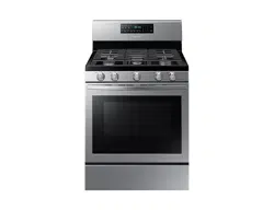
FEATURES OF YOUR NEW RANGE
Enhanced convenience. Better cooking. Easy maintenance. Your
new gas range has been designed to bring you these benets
and more.
Bigger is better
With a capacity of 5.8 cubic feet, your new range has more
space than many other leading brands in the United States and
Canadian markets. This means greater convenience for you
when cooking for the holidays or when entertaining.
A cooktop with 5 burners
Power burners, simmer burners, as well as a center oval burner
provide exible cooktop heat for a variety of cookware.
The center oval burner provides even heating over large areas,
so it is perfect for griddle cooking.
To prevent accidental tipping of the range, attach an
approved anti-tip device to the oor. (See Installing the
Anti-Tip Device in the Installation Instructions.) Check for
proper installation by carefully tipping the range forward.
The anti-tip device should engage and prevent the range
from tipping over.
If the range is pulled out away from the wall for any
reason, make sure the anti-tip device is reengaged after
the range has been pushed back into place.
Follow the installation instructions found in the Installation
Manual. Failure to follow these instructions can result in
death, serious personal injury, and/or property damage.

4 English
Contents
ContentsContents
Important safety instructions 5
SAFETY SYMBOLS 5
CALIFORNIA PROPOSITION 65 WARNING 6
IMPORTANT SAFETY PRECAUTIONS 6
GAS WARNINGS 11
IN THE COMMONWEALTH OF MASSACHUSETTS 12
ELECTRICAL WARNINGS 13
GROUNDING INSTRUCTIONS 14
INSTALLATION WARNINGS 14
SURFACE BURNER WARNINGS 17
OVEN WARNINGS 19
ELECTRIC WARMING DRAWER OR LOWER STORAGE DRAWER WARNINGS 21
SELF-CLEANING OVEN WARNINGS 21
PROPER COOKING OF MEAT AND POULTRY 22
Introducing your new range 23
Overview 23
Surface cooking 26
Lighting a gas surface burner 26
Manually lighting a gas surface burner 26
Flame size selection 26
Gas surface burners and control knobs 26
Cookware usage 27
Center burner grate 28
Wok grate (NX58*565*** Only) 28
Using the griddle 29
Operating the oven 30
Oven control panels and displays 30
Setting the clock 33
Setting the timer on/off 34
Positioning the oven racks 35
Using the gliding rack (NX58*565*** Only) 36
Oven vent 37
Oven light 37
Baking 38
Convection baking and roasting 39
Timed cooking 42
Delay timed cooking 44
Broiling 46
Keep warm 48
Using the easy cook feature 48
Air Fry mode (Model NX58*751***) 50
Favorite cooking 52
Sabbath function 54
Extra features 56
Using the warming drawer 58
About the warming drawer (Model NX58*565*** Only) 58
Turning the warming drawer on or off 58
Maintaining your appliance 59
Care and cleaning of the oven 59
Care and cleaning of the cooktop 63
Changing the oven light 67
Removing and replacing the oven door 67
Removing and replacing the warming drawer
(Model NX58*565***) 69
Removing and replacing the storage drawer
(Model NX58*560***, NX58*751***) 70
Self-cleaning oven 71
Troubleshooting 74
Troubleshooting 74
Troubleshooting and information codes 80
Warranty (U.S.A) 80
Warranty (CANADA) 82
English 5
Important safety instructions
SAVE THESE INSTRUCTIONS
READ ALL INSTRUCTIONS BEFORE USING THIS APPLIANCE
All electrical and gas equipment with moving parts can be
dangerous. Please read the important safety instructions for
this appliance in this manual. The instructions must be followed
to minimize the risk of injury, death, or property damage.
Save this manual. Please Do Not Discard.
SAFETY SYMBOLS
What the icons and signs in this user manual mean:
WARNING
There is a risk of death or serious personal injury.
CAUTION
There is a risk of personal injury or property damage.
CAUTION
To reduce the risk of re, explosion, electric shock, or personal
injury when using your gas range, follow these basic safety
precautions:
Important safety instructions
Do NOT attempt.
Do NOT disassemble.
Do NOT touch.
Follow directions explicitly.
Unplug the power cord from the electrical outlet.
Make sure the range is plugged into an earth grounded
electrical outlet to prevent electric shock. An outlet
equipped with a Ground Fault Interrupter (GFI) is highly
recommended.
Call the service center for help. see page 85.
Note
These warning icons are here to prevent injury to you and
others.
Please observe them explicitly.
Do not discard this manual. Please keep it in a safe place for
future reference.
6 English
Important safety instructions
Important safety instructions
SAVE THESE INSTRUCTIONS
CALIFORNIA PROPOSITION 65 WARNING
WARNING
Cancer and Reproductive Harm - www.P65Warnings.ca.gov.
IMPORTANT SAFETY PRECAUTIONS
WARNING
Follow basic precautions when installing and using this range
to reduce the risk of re, electrical shock, injury, or death to
persons, including:
Installation and Service
This range must be properly located and installed in
accordance with the installation instructions before it is
used.
Professional installation is strongly recommended.
Due to the size and weight of the range, it is highly
recommended that two or more people move or install this
appliance.
All ranges can tip over and cause severe injuries. Install
the anti-tip device packed with this range following the
instructions found in the Installation Instructions.
Never try to repair or replace this appliance on your own
unless it is specically recommended in this manual. This
appliance should be serviced only by a qualied service
technician.
Know the location of the gas shut-off valve and how to
shut it off if necessary.
Properly remove or destroy the packaging materials after
the appliance is unpacked.
Electrical/Mechanical
Unplug or disconnect power before servicing.
Do not tamper with the controls.
Grates and griddles (if equipped) are heavy. They can be
dangerous if dropped.
The inner portion of the split oven rack (if equipped) could
drop down accidentally if not assembled properly. Place
the inner rack in the proper position within the outer rack.
Always position the oven racks at the same level on each
cavity side. Uneven racks could cause food to slide to the
lower side, posing a risk of burns.

English 7
Important safety instructions
SAVE THESE INSTRUCTIONS
Danger to Children
Do not store any object of interest to children on the
cooktop or backguard of the range. Children climbing
on the range to reach items could be killed or seriously
injured.
The inner rack of the Split Rack can be dropped if it is not
assembled properly. Place the Inner rack in the proper
place on the Outer rack. Always insert the rack or split
rack assembly (if equipped) on the same level of the oven
cavity side.
Keep children away from the door when opening or
closing it as they may bump themselves on the door or
catch their ngers in the door.
Keep all packaging materials out of reach of children.
Children may play with them. Failure to dispose of plastic
bags could result in suffocation.
Do not leave children alone or unattended in an area
where a range is in use. They should never be allowed to
sit or stand on any part of a range.
Do not let little children touch the range.
The cooktop grates and griddle (if equipped) are heavy
and presents a risk of injury if dropped on a foot. Teach
children not to touch or play with grates or griddle.
Teach children not to touch or play with the controls or
any part of the range.
We recommend you utilize the control/door lockout
feature to reduce the risk of mis-use by children.
Before disposing of the range, cut off the power cord
to prevent it from being connected to a power source.
Remove the door to prevent children and animals from
getting trapped.

8 English
Important safety instructions
Important safety instructions
SAVE THESE INSTRUCTIONS
Fire
Do not touch oven burners, drawer burners, or interior
surfaces of the oven during or immediately after cooking.
Cooking surfaces, grates, cooktop burners, and caps, as
well as oven walls may be hot even though they are dark
in color. Interior oven surfaces can become hot enough
to cause burns. During and after use, do not touch or
let clothing or other ammable materials contact oven
burners, drawer burners, or interior surfaces of the oven
until they have had sufcient time to cool.
Do not let a pot holder touch a hot heating element. Do not
use a towel or other bulky cloth as a pot holder.
Do not use your range to heat unopened food containers
or to dry wet items or clothing.
Keep oven vent ducts unobstructed. Clean vents frequently
to avoid grease buildup. See page 37. There can be slight
popping sound during oven cooking. This sound may occur
during the normal oven burner cycling, when the oven
burner ame is extinguished.
Never use your range for any purposes but cooking. Doing
so could result in carbon monoxide poisoning and/or
overheating of the oven.
Do not wear loose-tting or hanging garments while using
this appliance.
DO NOT STORE OR USE combustible materials, gasoline,
or other ammable vapors or liquids in the vicinity of this
appliance. See WHAT TO DO IF YOU SMELL GAS under the
Gas Warnings.
Do not pour water into the cooktop well while cleaning
the cooktop. This could leak down into the range gas and
electrical systems creating a risk of electrical shock or high
levels of Carbon Monoxide, due to corrosion of the gas
valves or ports.

English 9
Important safety instructions
SAVE THESE INSTRUCTIONS
Do not use water on a grease re. Water might cause a
grease re to explode, spreading the re and creating a
larger re and health hazard. To put out a grease re, turn
off the heat source and smother the re with tight-tting
lid or use a multipurpose dry chemical or foam-type re
extinguisher.
Never leave surface units unattended at high heat settings.
Boilovers cause smoke, and greasy spillovers could ignite.
Do not use a ame to check for gas leaks. Instead, use a
brush to spread a soapy water mixture around the area
you are checking. If there is a gas leak, you will see small
bubbles in the soapy water mixture at the point of the
leak.
Do not place portable appliances, or any other object other
than cookware on the cooktop. Damage or re could occur
if the cooktop is hot.
Do not attempt to operate this appliance if it is damaged,
malfunctioning, or has missing or broken parts.
Never place plastic, paper, or other items that could melt
or burn near the oven vents or any of the surface burners.
If the self-clean mode malfunctions, turn the oven off and
disconnect the power supply. Refer to pages 80 and 82 to
contact a qualied service technician.
There can be slight popping sound during oven cooking.

10 English
Important safety instructions
Important safety instructions
SAVE THESE INSTRUCTIONS
Steam and Vapors
Use care when opening the oven door. Let hot air or steam
escape before removing or placing food in a hot oven.
Use only dry pot holders. Putting moist or damp pot
holders on hot surfaces may result in burns from steam.
Surface Burner Warnings
• The burner head can be blocked by food or dust. Clean
the head if it appears blocked. If you clean the head
with water, assemble it only after it is completely dry.
If the head is wet, it might prevent the burners from
igniting.
• Do not pour water on the cooktop for cleaning. It can
get inside the range and cause the parts inside to rust.
• Only ignite the cooktop burners with the burner caps
in place. If the burner caps are not in place, you can
damage the controls or cause an unintended large or
dangerous ame.
• Heating of beverages can result in delayed eruptive
boiling. To prevent delayed eruptive boiling, ALWAYS
allow heated beverages to stand at least 20 seconds
after you have turned the burner off so that the
temperature in the liquid can stabilize. In the event of
scalding, follow these FIRST AID instructions:
- Immerse the scalded area in cold water for at least
10 minutes
- Cover with clean, dry dressing
- Do not apply any creams, oils or lotions
• The ‘Spark mark’ on the Dual burner head must be
placed beside the electrode when it is assembled to
prevent an abnormal ame.
• After turning on a surface burner, check to make sure
that the burner has ignited. Adjust the level of the
ame by turning the burner knob.
• When you set a burner to simmer, do not turn the
burner knob quickly. Watch the ame to make sure it
stays on.

English 11
Important safety instructions
SAVE THESE INSTRUCTIONS
GAS WARNINGS
WARNING
If the instructions in this manual are not followed exactly, a
re or explosion may result, causing death, personal injury, or
property damage.
If you smell gas:
1. Close the valve and do not use the range.
2. DO NOT light a match, candle, or cigarette.
3. DO NOT turn on any gas or electric appliances.
4. DO NOT touch any electrical switches or plug a power cord
into an outlet.
5. DO NOT use any phone in your building.
6. Clear the room, building, or area of all occupants.
7. Immediately call your gas supplier from a neighbor’s phone.
Follow the gas supplier’s instructions.
8. If you cannot reach your gas supplier, call the re
department.
Read instructions completely and carefully.
Installation of this range must conform with local codes
or, in the absence of local codes, with the National Fuel
Gas Code, ANSI Z223.1/NFPA.54, latest edition. In Canada,
installation must conform with the current Natural Gas
Installation Code, CAN/CGA-B149.1, or the current Propane
Installation Code, CAN/CGA-B149.2, and with local codes
where applicable. This range has been design-certied by
ETL according to ANSI Z21.1, latest edition, and Canadian
Gas Association according to CAN/CGA-1.1, latest edition.
Do not install this range in a place which is exposed to a
strong draft.
Installation and service must be performed by a qualied
installer, service agency, or gas supplier.
Have the installer show you the location of the gas shut-
off valve and how to shut it off.
Always use NEW exible connectors when installing a gas
appliance. Never reuse old exible connectors. The use of
old exible connectors can cause gas leaks and personal
injury.
12 English
Important safety instructions
Important safety instructions
SAVE THESE INSTRUCTIONS
Never use this appliance as a space heater to heat or
warm the room. Doing so may result in carbon monoxide
poisoning and overheating of the oven.
Never block the oven vents (air openings). They provide
the air inlet and exhaust that are necessary for the oven to
operate properly with correct combustion.
Do not lean on the range as you may turn the control
knobs inattentively.
Do not stand on top of the appliance or place objects
(such as laundry, an oven cover, lighted candles, lighted
cigarettes, dishes, chemicals, metal objects, etc.) on the
appliance.
• Items, such as a cloth, may get caught in the door.
• This may result in electric shock, re, problems with
the product, or injury.
IN THE COMMONWEALTH OF MASSACHUSETTS
This product must be installed by a licensed plumber
or gas tter qualied or licensed by the State of
Massachusetts.
When using ball-type gas shut-off valves, you must use
the T-handle type.
Multiple exible gas lines must not be connected in series.
English 13
Important safety instructions
SAVE THESE INSTRUCTIONS
ELECTRICAL WARNINGS
Comply with the following electrical instructions and
requirements to avoid death, personal injury from electric
shock, and/or property damage from re:
1. Plug into a grounded 3-prong outlet.
2. DO NOT remove the ground prong.
3. DO NOT use an adapter.
4. NEVER use an extension cord.
Use a dedicated 120-volt, 60-Hz, 20-amp, AC, fused
electrical circuit for this appliance. A time-delay fuse or
circuit breaker is recommended. DO NOT plug more than
one appliance into this circuit.
The range is supplied with a 3-pronged grounded plug.
This cord MUST be plugged into a mating, grounded
3-prong outlet that meets all local codes and ordinances. If
you are unsure your electrical outlet is properly grounded,
have it checked by a licensed electrician.
If codes permit the use of a separate ground wire, we
recommend that a qualied electrician determine the
proper path for this ground wire.
Electrical service to the range must conform to local codes.
Barring local codes, it should meet the latest ANSI/NFPA
No. 70 – Latest Revision (for the U.S.) or the Canadian
Electrical Code CSA C22.1 – Latest Revisions.
It is the personal responsibility of the appliance owner to
provide the correct electrical service for this appliance.
NEVER connect the ground wire to plastic plumbing lines,
gas lines, or hot water pipes.
DO NOT modify the plug provided with the appliance.
DO NOT put a fuse in a neutral or ground circuit.
14 English
Important safety instructions
Important safety instructions
SAVE THESE INSTRUCTIONS
GROUNDING INSTRUCTIONS
Grounding a range with a cord connection:
This appliance must be Earth grounded. In the event
of a malfunction or breakdown, grounding will reduce
the risk of electrical shock by providing a path for the
electric current. This appliance is equipped with a cord
having a grounding plug. The plug must be rmly plugged
into an outlet that is properly installed and grounded in
accordance with the local codes and ordinances.
WARNING
Improper connection of the grounding plug can result in a risk
of electric shock. Check with a qualied electrician if you are
not sure whether the appliance is properly grounded.
NEVER modify the plug provided with the appliance. If it
does not t the existing outlet, have a qualied electrician
install a proper outlet.
INSTALLATION WARNINGS
Have your range installed and properly grounded by
a qualied installer, in accordance with the installation
instructions. Any adjustment and service should be
performed only by qualied gas range installers or service
technicians.
Be sure your range is correctly installed and adjusted by a
qualied service technician or installer for the type of gas
(natural or LP) you will use. For your range to utilize LP
gas, the installer must replace the 5 surface burner orices
and 2 oven orices with the provided LP orice set, and
reverse the GPR adapter.
WARNING
These adjustments must be made by a qualied service
technician in accordance with the manufacturer’s instructions
and all codes and requirements of the authority having
jurisdiction. Failure to follow these instructions could
result in serious injury or property damage. The qualied
agency performing this work assumes the gas conversion
responsibility.

English 15
Important safety instructions
SAVE THESE INSTRUCTIONS
Do not attempt to repair or replace any part of your range
unless it is specically recommended in this manual. All
other service should be referred to a qualied technician.
This appliance must be properly grounded. Plug your
range into a 120-volt grounded outlet that is only used
for this appliance. Do not remove the grounding (third)
prong from the plug. Firmly plug the power cord into the
wall outlet. If you are not sure your electrical outlet is
grounded, it is your personal responsibility and obligation
to have a properly grounded, three-prong outlet installed
in accordance with local and national codes. Do not use a
damaged power plug or loose wall outlet. Do not use an
extension cord with this appliance. In addition, do not use
an adapter or otherwise defeat the grounding plug. If you
do not have a proper outlet or have any doubts about the
outlet, consult a licensed electrician.
Locate the range out of kitchen trafc paths and drafty
locations to prevent poor air circulation.
This appliance should be positioned so that the power plug
is easily accessible.
Do not install in an area exposed to dripping water or
outside weather conditions.
Remove all packaging materials from the range before
operating it. These materials can ignite, causing smoke
and/or re damage.
Install this appliance on a level and hard oor that can
support its weight. Synthetic ooring, like linoleum, must
withstand 180 °F (82 °C) temperatures without shrinking,
warping, or discoloring. Never install the range directly
over interior kitchen carpeting unless a sheet of 0.25”
plywood or a similar insulator is placed between the range
and carpeting.
16 English
Important safety instructions
Important safety instructions
SAVE THESE INSTRUCTIONS
Do not block or cover the vents (air openings). The vents
allow for air circulation that is necessary for the range
to operate properly with correct combustion. Blocking or
covering the vents may cause incorrect combustion which
could result in gas leaks and re. Air openings are located
behind the range, under the oven control panel, at the
top and bottom of the oven door, and under the lower
warming or storage drawer.
Large scratches on or sharp blows to the door glass can
cause the glass to break or shatter.
Make sure the wall coverings around the range can
withstand heat, up to 200 °F (93 °C), generated by the
range.
Avoid placing cabinets above the range. This reduces
the hazard caused by reaching over the open ames of
operating burners.
Do not put any combustible material or items around the
range.
If cabinets are placed above the range, allow a minimum
clearance of 40” (102 cm) between the cooking surface
and the bottom of unprotected cabinets.
Install a ventilation hood or an externally vented Over
The Range Microwave Oven over the range cooktop that
is as wide as the range, centered over the range, and
projects forward beyond the front of the cabinets. See the
Installation instructions.
Remove all tape and packaging. Make sure the burners are
properly seated and level.
Remove any accessories from the oven and/or lower
drawer.
Check to make sure no range parts have come loose during
shipping.
English 17
Important safety instructions
SAVE THESE INSTRUCTIONS
SURFACE BURNER WARNINGS
WARNING
Follow basic precautions when installing and using this range
to reduce the risk of re, electrical shock, injury, or death to
persons, including:
Use proper pan sizes. Avoid pans that are unstable or
warped. Select cookware having at bottoms large enough
to cover the burner grates. To avoid spillovers, make sure
cookware is large enough to contain your food. This will
save cleaning time and prevent hazardous accumulations
of food, since heavy spattering or spillovers left on the
range can ignite. Use pans with handles that can be easily
grasped and remain cool.
Do not use pots or pans larger than the grate on a grate.
Using pots or pans larger than a grate may cause the pots
or pans to discolor or deform. It can also cause units or the
wall around the grate to ignite and may generate excess
carbon monoxide.
Always use the LITE position when igniting the top
burners. Make sure the burners have ignited.
If ignition fails, turn the knob to Off and wait until the gas
already emitted has dissipated. If you keep the knob in
the LITE position without proper ignition, the emitted gas
might cause an explosion.
Never leave the surface burners unattended at HIGH ame
settings. Boilovers cause smoking, and greasy spillovers
can ignite.
Stand away from the range when frying.
Adjust the top burner ame size so it does not extend
beyond the edge of the cookware. Flames that extend past
cookware edges can be hazardous.
To decrease spattering when cooking foods with lots of
liquid, such as meat sauce or stew, adjust the the ame to
low and stir frequently.
Only use dry pot holders. Pot holders with moisture in
them can release steam and cause burns if they come in
contact with hot surfaces.

18 English
Important safety instructions
Important safety instructions
SAVE THESE INSTRUCTIONS
Keep pot holders away from open ames when lifting
cookware. Never use a towel or bulky cloth in place of a
pot holder.
Keep all plastic away from the surface burners or any open
ame.
When using glass cookware, make sure it is designed for
top-of-range cooking.
Always make sure cookware handles are turned to the side
or rear of the cooktop, but not over other surface burners.
This will minimize the chance of burns, spillovers, and the
ignition of ammable materials that can be caused if pots
or pans are bumped accidently.
Do not wear loose or hanging garments when using the
range. They could ignite and burn you if they touch a
surface burner.
Take care that your hands do not touch the burners when
they are on. Turn off the burners when you change a pan
or pot.
Always heat frying oils slowly, and watch as they heat. If
you are frying foods at high heat, carefully watch during
the cooking process. If a combination of fats or oils are to
be used during frying, they need to be stirred together
before heating.
Use a deep fryer thermometer whenever possible. This
prevents overheating the fryer beyond the smoking point.
Use as little oil as possible for shallow or deep-fat frying.
Using too much oil can cause spillovers when food is
added.
Items should always be removed from the cooktop when
they are done cooking.
Do not leave plastic items on top of the range. Hot air from
the vents on top of the range can melt the plastic and may
cause pressure build-up in closed plastic containers. The
melted plastic may clog the vents at the rear of the range.
Clogged vents may cause incorrect combustion which
could result in gas leaks and re. And you may get severe
burns if you touch the surfaces near the vent while the
oven is operating.

English 19
Important safety instructions
SAVE THESE INSTRUCTIONS
This cooktop is not designed to ame foods or cook with
a wok or wok ring attachment. If foods are amed, they
should only be amed under a ventilation hood that is on.
Always make sure foods being fried are thawed and dried.
Moisture of any kind can cause hot fat to bubble up and
over the sides of the pan.
Never move a pan or deep-fat fryer full of hot fat. Always
let it cool before moving.
Always make sure the controls are OFF and the grates are
cool before you remove them to prevent any possibility of
burning.
If the range is located near a window, NEVER hang long
curtains or paper blinds on that window. They could blow
over the surface burners and ignite, causing a re hazard.
Grease is ammable and should be handled very carefully.
Never try to extinguish a grease re with water.
If you smell gas, turn off the gas to the range and call a
qualied service technician. NEVER use an open ame to
locate a leak.
Always turn off the surface burner controls before
removing cookware. All surface burner controls should be
turned OFF when you are not cooking.
Always turn the burners off before you go to sleep or go
out.
OVEN WARNINGS
WARNING
NEVER cover any holes or passages in the bottom oven cover.
NEVER cover an entire oven rack with aluminum foil or like
material. Covering the bottom cover and/or racks blocks
airow through the oven and could cause carbon monoxide
poisoning.
Do not use aluminum foil or foil liners anywhere in the
oven. Misuse traps heat and could cause a re hazard or
damage the range.
Always follow the manufacturer’s directions when using
cooking or roasting bags in the oven.

20 English
Important safety instructions
Important safety instructions
SAVE THESE INSTRUCTIONS
DO NOT clean the door gasket. The door gasket is essential
for a good seal. Care should be taken not to damage or
move the gasket.
Do not strike the oven glass. Do not spray water onto the
oven glass when the oven is on or just after you have
turned the oven off.
Stand away from the range when opening the door of a
hot oven. The escaping hot air and steam can cause burns.
Do not use the oven for storage. Stored items can be
damaged or ignite.
Keep the oven free from grease buildup.
Reposition oven racks only when the oven is cool to
prevent burning or personal injury.
Do not heat unopened containers. Pressure in the container
could build up, resulting in an explosion and/or personal
injury.
Only use glass cookware that is recommended for use in
gas ovens.
This prevents re are-ups from stored grease buildup.
Do not broil meat too close to the burner ame. Trim
excess fat from meat before cooking. Meat fat can ignite,
causing a re hazard.
If a grease re should occur in the oven, turn off the oven
by pressing the Clear/Off pad. Keep the oven door closed
to put out the re.
Always bake and/or broil with the oven door closed.
Broiling with the door partially or fully open can damage
the surface burner control knobs and even the kitchen
counter.
Keep the appliance area clear and free from combustible
materials, gasoline, and other ammable vapors and
liquids.
Do not use the oven to dry paper, clothes, etc. Such items
might catch re if overheated.
English 21
Important safety instructions
SAVE THESE INSTRUCTIONS
ELECTRIC WARMING DRAWER OR LOWER
STORAGE DRAWER WARNINGS
The warming drawer is designed to keep hot cooked foods
at serving temperature. Always start with hot food. Cold
or room-temperature foods cannot be heated, warmed, or
cooked in the warming drawer.
Do not touch the interior drawer surface or heating
element. These surfaces may be hot and could burn you.
Use care when opening the drawer. Escaping hot air and/
or steam can cause burns or personal injury.
Do not use aluminum foil to line the lower drawer.
Aluminum foil will trap heat and alter the warming
performance of the drawer. It could also damage the
interior nish.
Never use the lower/warming drawer in the upper oven.
Never put the lower/warming drawer in the upper oven
during a self-cleaning cycle.
Never leave jars or cans of fat drippings in or near the
lower drawer.
Do not leave or store paper products, plastics, canned food,
or combustible materials in the drawer. Do not use the
drawer to dry newspapers. They could ignite. Plastic items
could melt.
SELFCLEANING OVEN WARNINGS
WARNING
Follow basic precautions when installing and using this range
to reduce the risk of re, electrical shock, injury, or death to
persons, including:
Do not leave children unattended near the range during a
self-cleaning cycle. The outside surfaces of the range get
hot enough to burn if touched.
Stand away from the range when opening the oven door
after a self-cleaning cycle. The oven will be VERY HOT and
the escaping hot air and steam can cause burns.

22 English
Important safety instructions
Important safety instructions
SAVE THESE INSTRUCTIONS
PROPER COOKING OF MEAT AND POULTRY
Make sure all meat and poultry is cooked thoroughly.
Meat should always be cooked to an internal temperature
of 160 °F (71 °C). Poultry should always be cooked to an
internal temperature of 180 °F (82 °C). Cooking these foods
to these minimally safe temperatures can help protect you
and your family from food bourne illnesses.
Remove all racks and other utensils from the oven before
starting a self clean cycle. The oven racks may become
damaged, and foreign objects could ignite if left within the
oven cavity.
Wipe off any excess spillage before using the self-cleaning
operation.
Remove all cookware, oven probes, and any aluminum foil
before using the self-cleaning operation.
Never self-clean with the lower drawer or drawer pan
placed in the oven.
If the self-cleaning operation malfunctions, turn off the
oven, disconnect the power supply, and contact a qualied
service technician.
Do not use oven cleaners. Commercial oven cleaners or
oven liners should NEVER be used in or around any part
of the oven. Residue from oven cleaners will damage the
inside of the oven during a self-cleaning operation.
Nickel oven shelves should be removed from the oven
during a self-cleaning cycle. Porcelain-coated oven shelves
may be cleaned in the oven during a self-cleaning cycle.
English 23
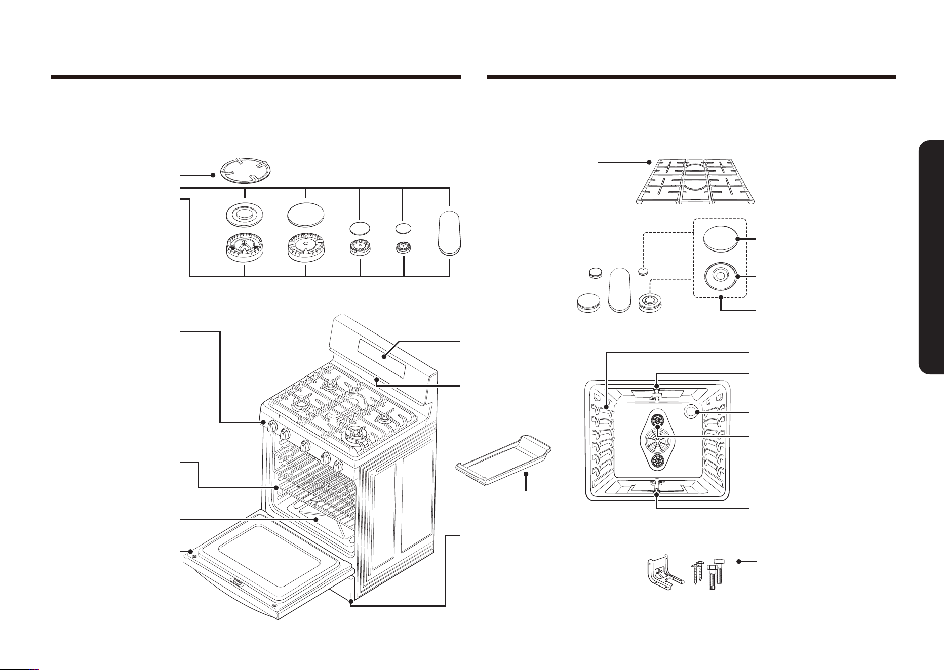
Introducing your new range
* Wok grate
* Cooktop burner caps
Cooktop burners
Cooktop burner heads (5)
Cooktop burner cups (5)
(not shown under burners)
Electrodes (5)
(not shown under burners)
COOKTOP COMPONENTS
Heavy duty, continuous
cast grates
- * Left burner grate
- * Center burner grate
- * Right burner grate
Note: the left and right
grates can be used
interchangeably.
* Cooktop burner control
knobs (5)
- Left-front burner control
- Left-rear burner control
- Center burner control
- Right-rear burner control
- Right-front burner control
OVEN COMPONENTS
* Oven racks (2)
Glide rack (1)
(as equipped)
Removable oven oor
DISPLAY
Flat surface
Concave line
Common use
OVEN COMPONENTS
Oven rack position guide
Broil oven burner
* Oven light (1)
Bake oven burner
ADJUSTABLE LEVELING
LEGS (4)
(not shown)
ANTI-TIP BRACKET KIT (1)
Convection fan (1)
Convection heater (not shown)
Griddle (1)
OVEN VENT
(centered under oven
control panel)
WARMING DRAWER COMPONENTS
Removable warming drawer (1)
Full-extension roller guide rails (2)
Electric heating element
(not shown under drawer)
Removable oven door
Introducing your new range
Overview
MODEL NX58*565***

24 English
Introducing your new range
Introducing your new range
MODEL NX58*560***
*Cooktop burner caps
Cooktop burners
Cooktop burner heads (5)
Cooktop burner cups (5)
(not shown under burners)
Electrodes (5)
(not shown under burners)
COOKTOP COMPONENTS
Heavy-duty continuous cast
grates
- *Left burner grate
- *Center burner grate
- *Right burner grate
*Cooktop burner control
knobs (5)
- Left-front burner control
- Left-rear burner control
- Center burner control
- Right-rear burner control
- Right-front burner control
OVEN COMPONENTS
*Oven racks (2)
Removable oven bottom
DISPLAY
OVEN COMPONENTS
Oven rack position guide
Broil oven burner
*Oven light (1)
Bake oven burner
ADJUSTABLE LEVELING
LEGS (4)
(not shown)
ANTI-TIP BRACKET KIT (1)
Convection fan (1)
Griddle (1)
OVEN VENT
(centered under oven
control panel)
STORAGE DRAWER COMPONENTS
Removable Storage drawer (1)
Removable oven door
If you need an accessory marked with an * (asterisk), please contact the Samsung Call Center using the phone number listed on the last page of this manual or visit our on-
line parts web site at www.samsungparts.com.
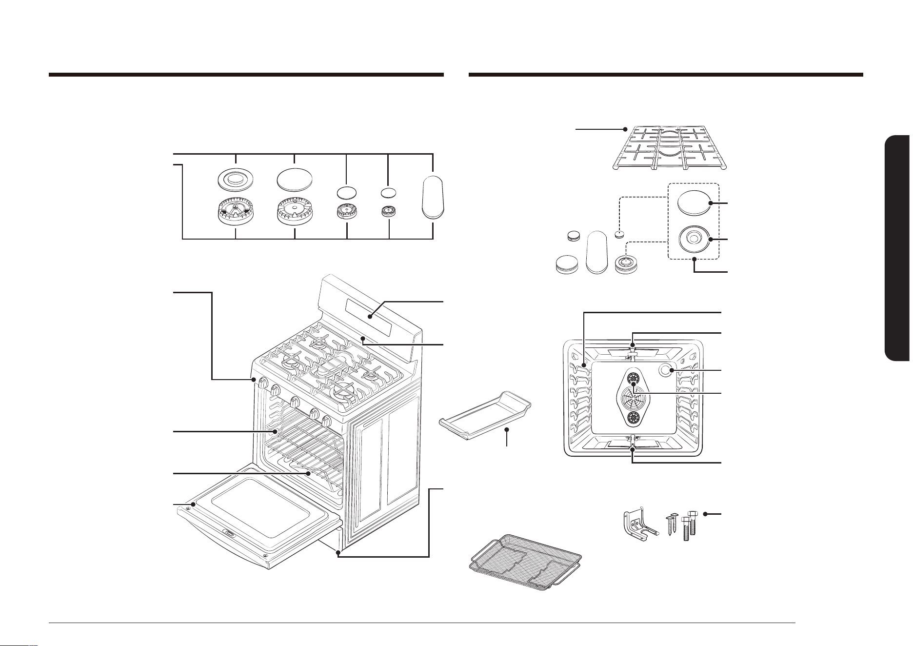
English 25
Introducing your new range
MODEL NX58*751***
* Cooktop burner caps
Cooktop burners
Cooktop burner heads (5)
Cooktop burner cups (5)
(not shown under burners)
Electrodes (5)
(not shown under burners)
Flat surface
Concave line
Common use
COOKTOP COMPONENTS
Heavy duty, continuous
cast grates
- * Left burner grate
- * Center burner grate
- * Right burner grate
Note: the left and right
grates can be used
interchangeably.
*Cooktop burner control
knobs (5)
- Left-front burner control
- Left-rear burner control
- Center burner control
- Right-rear burner control
- Right-front burner control
OVEN COMPONENTS
*Oven racks (2)
Removable oven bottom
DISPLAY
OVEN COMPONENTS
Oven rack position guide
Broil oven burner
*Oven light (1)
Bake oven burner
ADJUSTABLE LEVELING
LEGS (4)
(not shown)
ANTI-TIP BRACKET KIT (1)
Convection fan (1)
Griddle (1)
OVEN VENT
(centered under oven
control panel)
STORAGE DRAWER COMPONENTS
Removable Storage drawer (1)
Removable oven door
Air fry tray (1)
26 English
Surface cooking
Surface cookingSurface cooking
WARNING
BEFORE USING THE SURFACE BURNERS, make sure to follow all the safety
warnings and precautions listed on page 6. Failure to do so could result in product
damage, personal injury, and/or death.
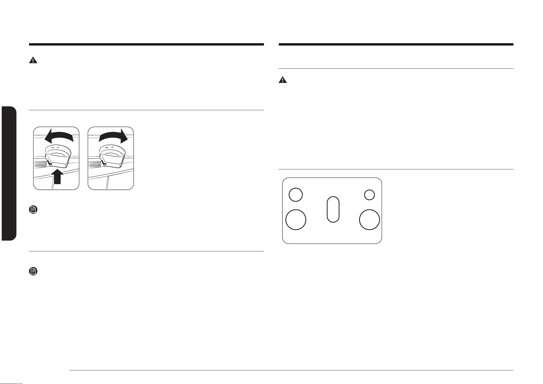
Lighting a gas surface burner
Make sure all surface burners are positioned and assembled properly.
1. Push in and turn the control knob to the
LITE position. You will hear a “clicking”
sound indicating the electronic ignition
system is working properly.
2. After the surface burner lights, turn the
control knob to adjust the power setting
of the surface burner and turn off the
electronic ignition system.
NOTE
We highly recommend using the left rear side burner for simmering tomato sauce
and right rear side burner for melting chocolate.
Manually lighting a gas surface burner
If a power failure occurs, the surface burners can still be lit manually.
NOTE
Use extreme caution when manually lighting a surface burner.
1. Hold a long gas grill lighter to the surface burner you want to light.
2. Push in and turn the control knob for that burner to the LITE position.
3. After the burner has lit, set the control knob and the burner to the desired
setting.
Flame size selection
WARNING
Flames larger than the bottom of the cookware will not result in faster heating,
but could result in a re hazard and/or personal injury.
The ames on the burners should always stay under the cookware. The ames
should never extend beyond the bottom surface and/or up the sides of the
cookware.
Always watch the ames when adjusting the heat setting with the control knob(s).
The ames should always match the size of the cookware being used.
Gas surface burners and control knobs
LR RR
LF RF
CENTER
Your gas range cooktop has ve gas
burners. All sealed cooktop burners use
an open-port design which provides easy
assembly and accurate and dependable
operation. The different burner sizes ensure
you have the proper heat source for the
desired cooking job.
The right rear side burner provides precise cooking performance for delicate foods
and foods that require low heat for long cooking times. The right rear side burner
lets you use the LO setting for a very low simmer setting.
The left rear side and center round burners are general-purpose burners that can
be used for most cooking. The HI to LO settings provide a wide range of cooking
temperatures to meet your cooking needs.
English 27
Surface cooking
Cookware usage
Using the correct cookware can prevent many problems, such as uneven cooking
or extended cooking times. Using the proper pans will reduce cooking times and
cook food more evenly. Look for the following pan characteristics:
• Flat bottom and straight sides.
• Tight-tting lid.
• Weight of handle does not tilt pan.
• Pan is well-balanced.
• Pan size matches the amount of food being prepared and the size of the
surface burner.
• Made of material that conducts heat well.
• The pot/pan diameter matches the surface burner ame diameter.
What your cookware is made of determines how evenly and quickly heat is
transferred from the surface burner to the pan bottom.
ALUMINUM: Excellent heat conductor. Some types of food will cause the aluminum
to darken. (Anodized aluminum cookware resists staining and pitting.)
COPPER: Excellent heat conductor, but discolors easily.
STAINLESS STEEL: Slow heat conductor with uneven cooking results. Is durable,
easy to clean, and resists staining.
CAST-IRON: A poor conductor, but retains heat very well. Cooks evenly once
cooking temperature is reached.
ENAMELWARE: Heating characteristics will vary depending on base material.
GLASS: Slow heat conductor. Glass cookware is designed for two usages—top-of-
range cooking or oven use. Only use cookware where it is designated to be used.
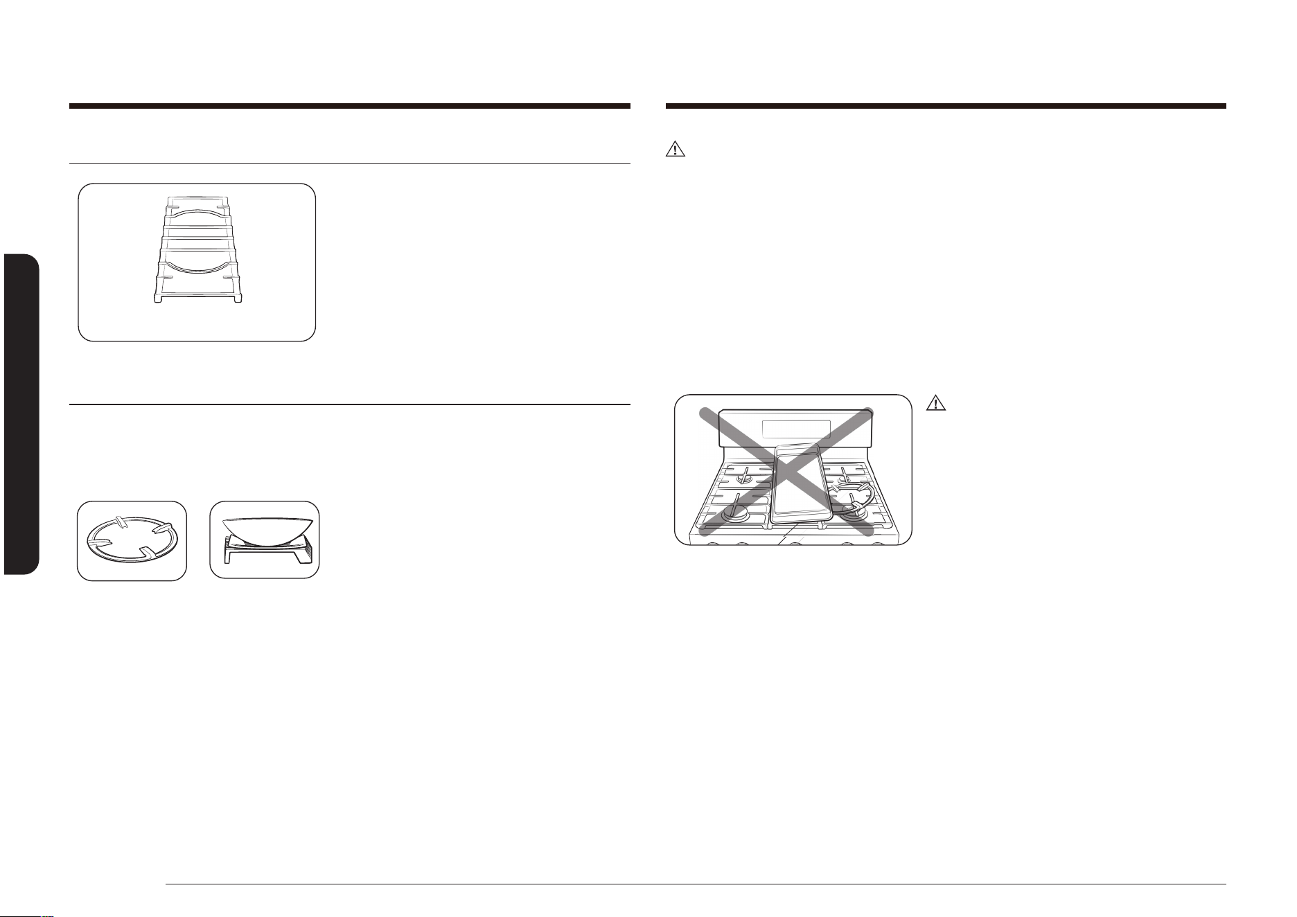
NOTE
Do not place a small pan or pot with a
bottom diameter of about 6” or less on the
center grate. It is likely that the pan or pot
will tip over. We strongly recommend you
place small-sized pots or pans on the rear of
either side grate.
The right and left front side burners provide maximium output. These burners can
also be used as general-purpose burners, but they are designed to provide quick
heat to large cookware. The right and left front side burners spread out the heat
with a larger circle of ames. This provides better heat distribution for larger
cookware (12”/30.5 cm) or larger pots and pans.
BURNER POSITION FUNCTION TYPE OF FOOD
RIGHT FRONT (RF) Quick heating Boiling Food
RIGHT REAR (RR) Low simmering
Chocolate, Casseroles,
Sauces
CENTER Griddle Cooking
Pancakes, Hamburgers,
Fried Eggs, Hot
Sandwiches
LEFT FRONT (LF) Quick heating Boiling Food
LEFT REAR (LR)
General heating
Low simmering
General Food
Tomato Sauce*,
Casseroles
NOTE
* Tomato sauce needs to be stirred during the low simmering.
The center oval burner can also be used for large pots and pans, but is designed
to be used with the center burner grate and/or the center griddle accessory (if
equipped).
The oval burner spreads out the heat more evenly over the large center cooking
area.
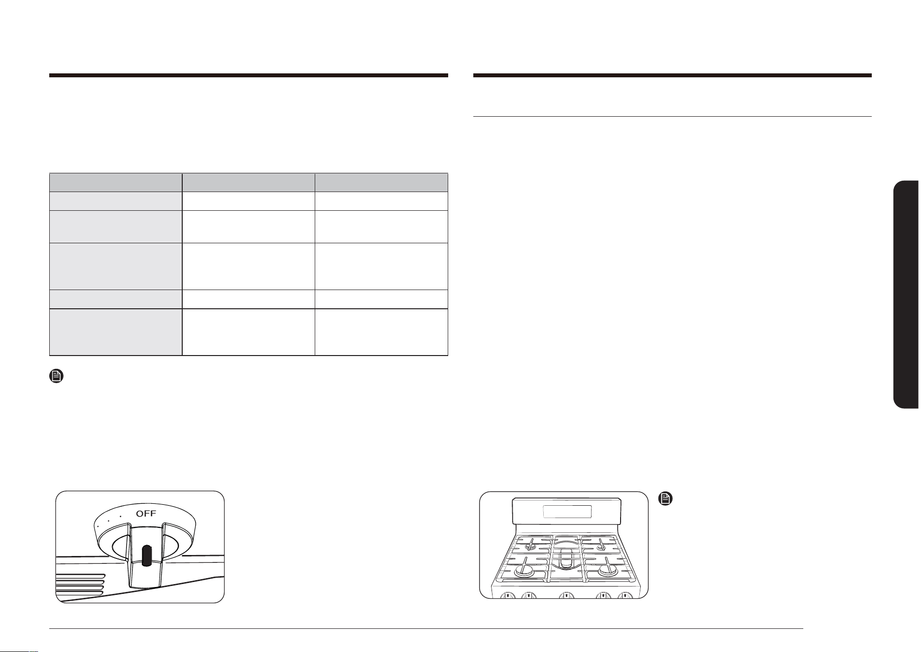
Each surface burner has a control knob
with settings from HI to LO. They also have
a LITE setting that is only used to light
the ame. The electronic ignition system
sparks when the control knob is in the LITE
position.
The surface burner indicator next to the
control knob shows which burner the knob
controls.
28 English
Surface cooking
Surface cooking
CAUTION
• Do not remove the wok grate until the cooktop grates, surfaces, and wok grate
are completely cooled.
• When using the cooktop, oven, or broil systems, the wok grate on the cooktop
may become very hot. Always use oven gloves when placing or removing the
wok grate.
• Do not use a pot or pan with a at bottom on the wok grate or a wok with a
diameter that is smaller than the wok ring diameter. If you do, it is likely that
the pan, pot, or wok will tip over.
• Using an oversized wok may cause the ames to spread out and damage the
surrounding cooktop.
• Make sure the wok sits securely on the wok grate.
CAUTION
Do not use the wok grate with the griddle
at the same time.
Center burner grate
Center burner grate
Samsung gas ranges come with a center
burner grate. This grate ts over the center
oval burner. The center burner grate should
not be placed over any other burners and
no other center stovetop grates should be
used with this range.
Wok grate (NX58*565*** Only)
Woks are often used for stir frying, pan frying, deep frying, and poaching.
The wok grate provided can support a 12-14” pan or wok.
How to use wok grate
1. Before placing the wok grate, make sure
that the burner is off and the grate is
completely cool.
2. Place the wok grate on either side grate.
3. Place the wok on the wok grate.
(Make sure that the wok sits securely on
the work grate.)
4. Turn on the burner and adjust the ame
size.
English 29
Surface cooking
How to cook: Preheat the griddle according to the guide below, and then adjust for
the cooking conditions.
Type of Food Preheat Time Preheat Condition Cook Condition
Pancakes 5 min 5 (MED-HI) 4 (MED)
Hamburgers 5 min 7 (HI) 5 (MED-HI)
Fried Eggs 5 min 7 (HI) 5 (MED-LO)
Bacon - None 4 (MED)
Breakfast Sausages 5 min 7 (HI) 5 (MED)
Grilled Cheese
Sandwich
4 min 7 (HI) 6 (MED-HI)
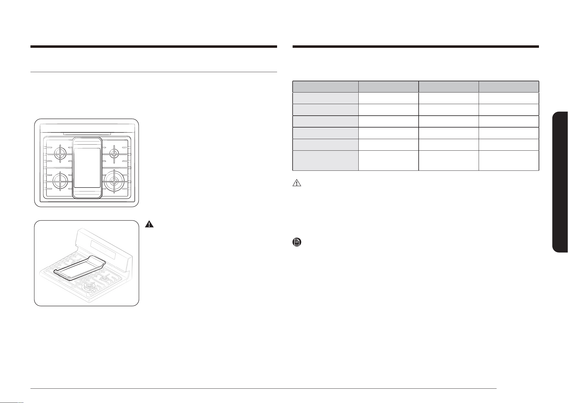
CAUTION
• DO NOT remove the griddle until the cooktop grates, surfaces, and griddle are
completely cooled.
• The griddle on the cooktop may become very hot when you use the cooktop,
oven, or broil systems. Always use oven gloves when placing or removing the
griddle.
NOTE
• Carefully put the griddle on the center grate.
• Griddle settings may need to be adjusted if the griddle is used for an extended
time.
• Your griddle will discolor over time as it becomes seasoned with use.
• After use, return the griddle to storage only after it has cooled.
Using the griddle
The non-xed coated griddle provides an extra-large cooking surface for meats,
pancakes, or other food usually prepared in a frying pan or skillet.
How to Place the Griddle: The griddle can only be used with the center burner. The
griddle must be properly placed on the center grate as shown in the gure below.
WARNING
DO NOT remove the center grate when
using the griddle.
30 English
Operating the oven
Operating the oven Operating the oven
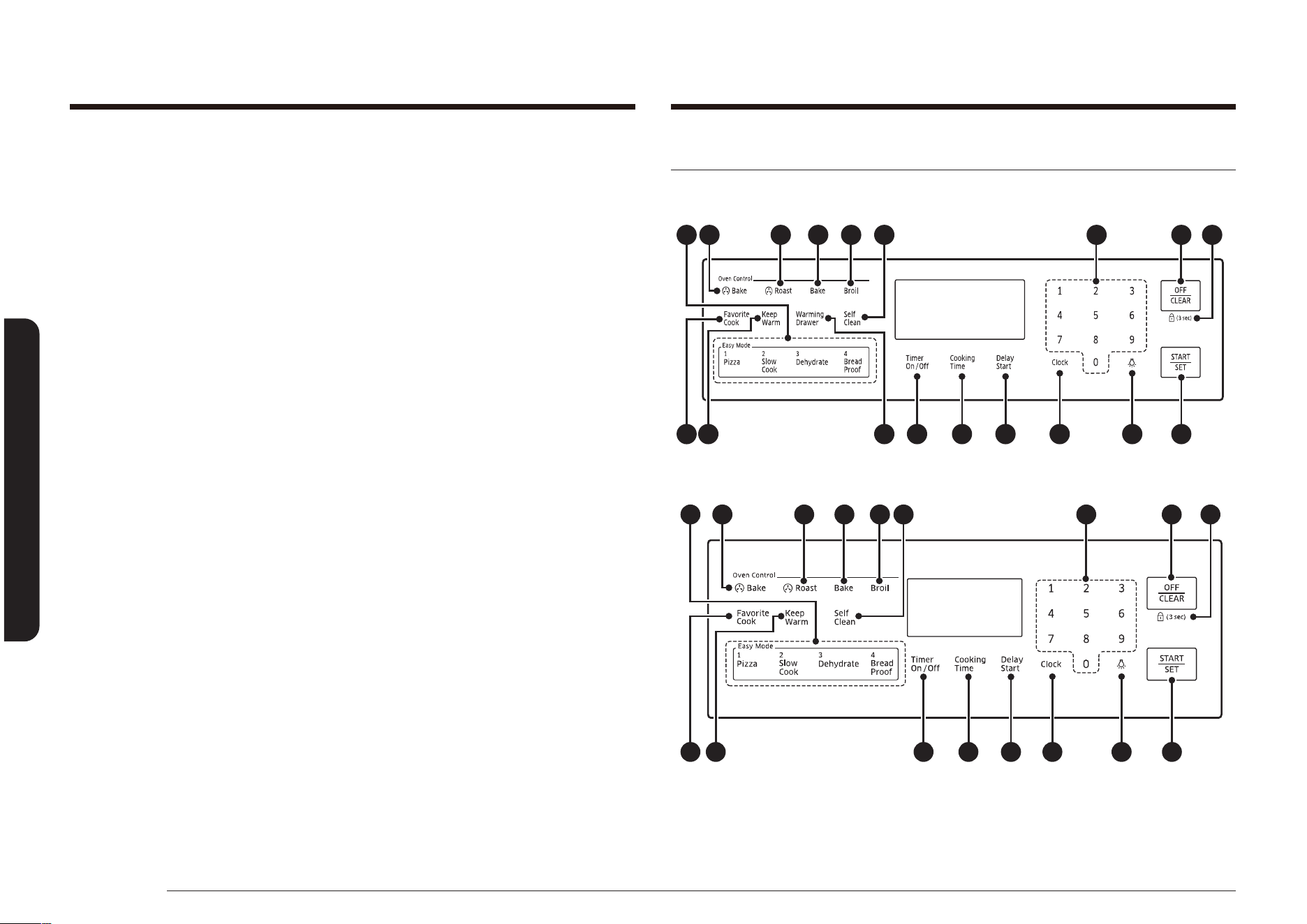
Oven control panels and displays
MODEL NX58*565***
03 04 05 09 07
15 14 16 17 18 06
08
12
11
13
01 02
10
MODEL NX58*560***
03 04 05 09 07
15 14 16 17 18 06
0802
12 10
01 11
Important Note:
• DO NOT overheat the griddle. This can damage the non-xed coating.
• DO NOT use metal utensils that can damage the griddle surface. Do not use the
griddle as a cutting board.
• DO NOT place or store items on the griddle.
• DO NOT turn the griddle over and use the underside for cooking. Use the top
side of the griddle only.
• DO NOT use the griddle for any purpose other than cooking.
• Avoid cooking extremely greasy foods. Grease spill overs can occur.
• The griddle can become hot when surrounding burners are in use.

English 31
Operating the oven
NOTE
All oven operations are controlled with electronic touch pads. Use the following
pads to program and operate all oven cooking, cleaning, and timing functions. All
programmed settings and cooking statuses will show on the digital display.
Special feature, oven, and time controls
01 EASY COOK: Press to recall the Easy cook recipe setting of the oven.
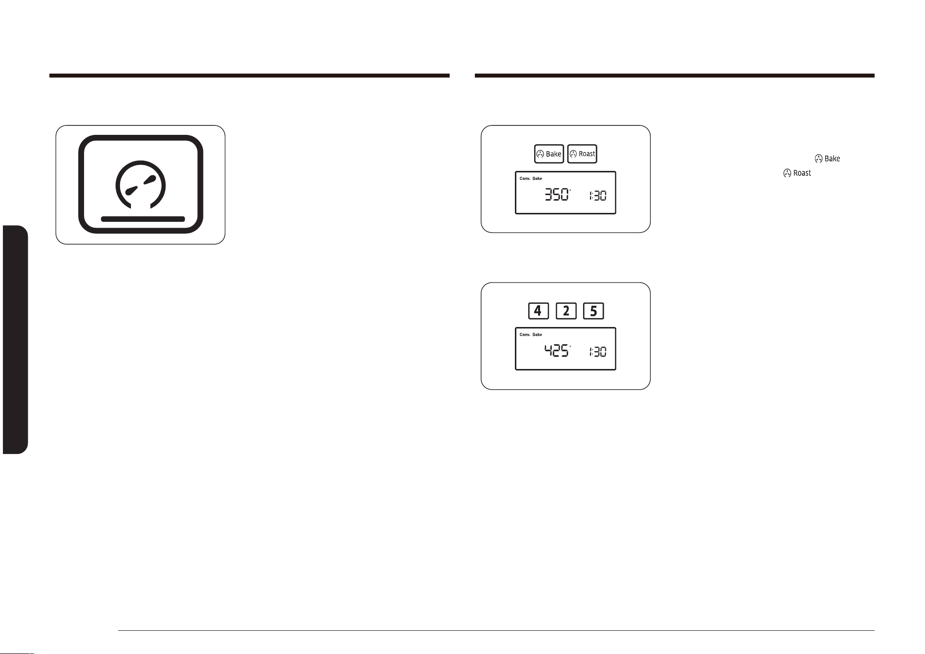
02 CONVECTION BAKE( ): Activates the convection bake function. Use this
function to cook large amounts of baked goods on multiple shelves at the
same time.
03 CONVECTION ROAST( ): Activates the convection roast function. Use this
function to cook large cuts of meat.
04 BAKE: Touch this pad to activate the Bake function. Evenly cooks food using
the bottom oven burner.
05 BROIL: Activates the Broil function. Cooks foods using the top oven burner
only.
06 START/SET: Touch this pad to start the oven cooking, cleaning, and/or timing
functions.
07 OFF/CLEAR: Press to cancel all oven operations except the clock and timer.
08 HOLD 3 SEC: Deactivates the control panel touch pads to prevent the oven
from accidentally being turned on. It also locks the oven door to prevent
accidental tipping of the range. Touch pads will not work and the oven door
will stay locked until this function is turned off.
09 NUMBER PADS: Touch these pads to set the desired times, temperatures, and
preset oven functions.
10 KEEP WARM: Touch this pad to keep cooked foods warm after cooking. This
lowers the oven temperature and maintains it at 150 °F to 200 °F
(66 °C to 93 °C).
11 SELF CLEAN: Activates the self-cleaning oven function. Uses very high heat to
burn off internal oven soilage.
MODEL NX58*751***
03 04 05 09 07
15 14 16 17 18 06
0802
12 10
01 11
32 English
Operating the oven
Operating the oven
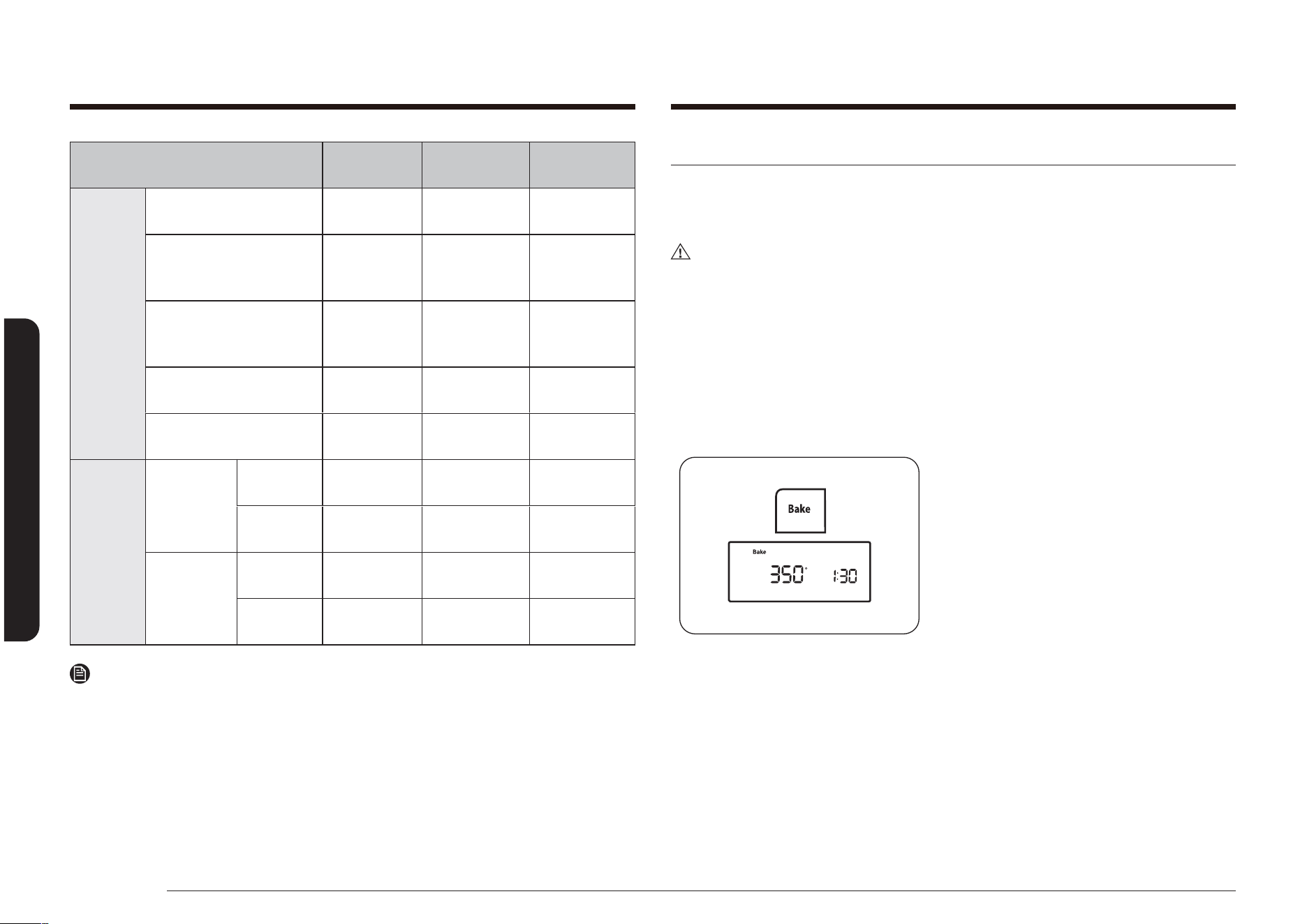
Minimum and maximum settings
All the features listed in the following chart have minimum and maximum
temperature or time settings.
FEATURE MINIMUM SETTING MAXIMUM SETTING
BAKE 150 °F (66 °C) 550 °F (288 °C)
BROIL Lo Hi
SELF-CLEAN 2 hours 4 hours
CONVECTION BAKE ( )
150 °F (66 °C) 550 °F (288 °C)
CONVECTION ROAST ( )
150 °F (66 °C) 550 °F (288 °C)
AIR FRY 350 °F (177 °C) 500 °F (260 °C)
KEEP WARM - 3 hours
WARMING DRAWER * - 3 hours
BREAD PROOF - 12 hours
* Model NX58*565*** Only
If you set Conversion On for Convection Bake and/or Convection Roast, you can
set the minimum temperature to 175 °F (79 °C).
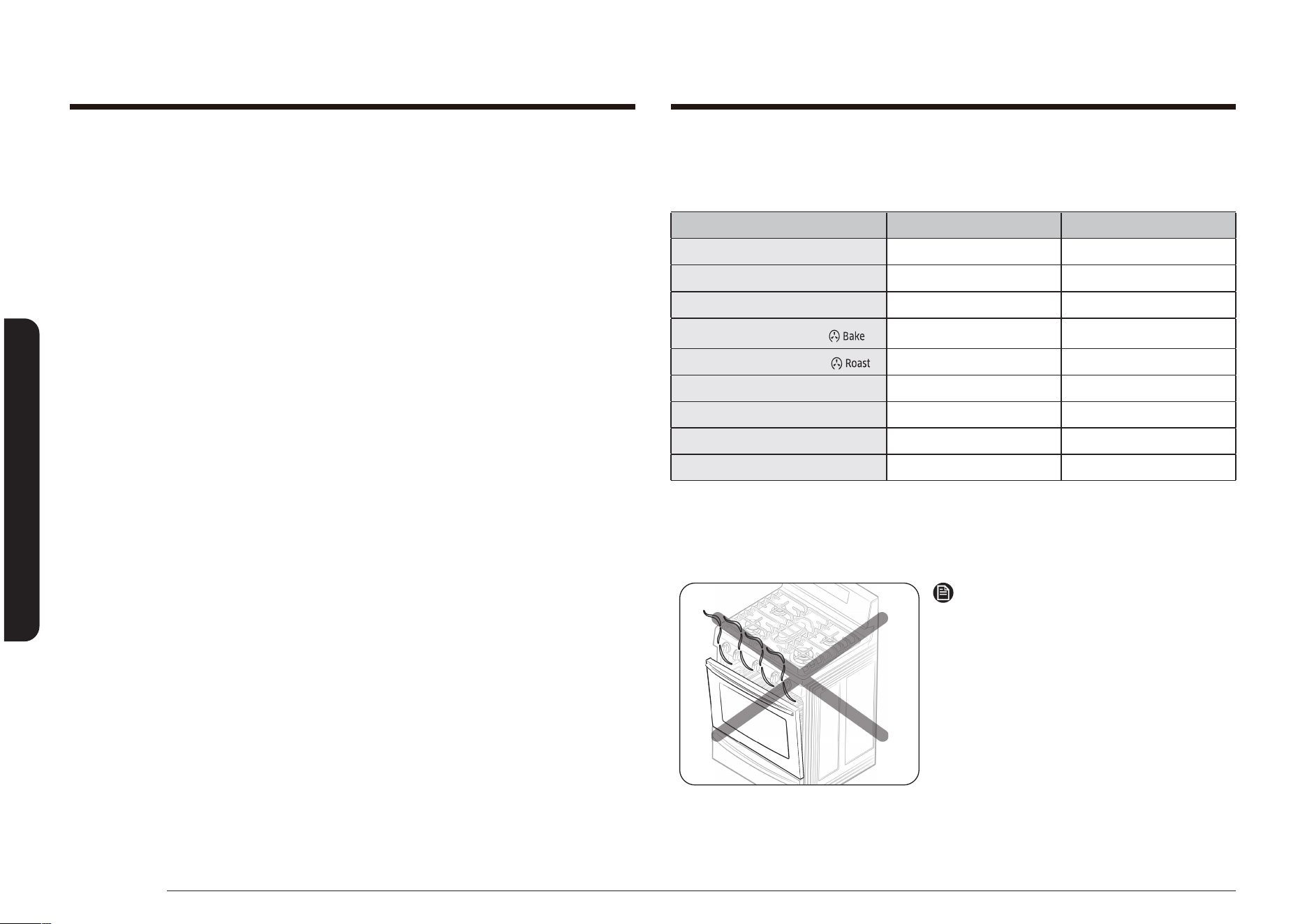
NOTE
Always bake and/or broil with the oven
door closed.
If you open the oven door while the oven
is operating and leave it open, the oven
burner will stop in 1 minute. This is not a
product failure. The oven will automatically
start again when you close the door.
Application mode: Conv. Bake, Conv. Roast,
Bake, Broil, Pizza, Slow Cook, Dehydrate,
Bread Proof, Favorite Cook, Air Fry.
12 FAVORITE COOK: Activates the favorite cook feature. This feature lets you
preprogram up to three frequently used cooking cycles so they can be set and
started with the touch of a button.
13 WARMING DRAWER (MODEL NX58*565***): Touch this pad to activate the
warming drawer. An electric heating element under the drawer uses three
settings to keep cooked foods warm.
14 COOKING TIME: Touch this pad, and then the desired amount of time you want
your food to cook. The oven will automatically shut off when the time has
elapsed.
15 TIMER ON/OFF: Touch to select the timer feature. Activates a kitchen timer for
the desired amount of time.
16 DELAY START: Allows you to set the oven to start and stop automatically.
Use with Bake, Convection Bake, Convection Roast, Cook Time, or Self Clean
functions.
17 CLOCK: Allows you to set the clock.
18 OVEN LIGHT: Touch this pad to turn the oven light on or off.

English 33
Operating the oven
How to change between a 12-hour and 24-hour display
1. Press and hold the Clock and 0 pads for
3 seconds.
The display will show the present mode
(e.g., 12Hr).
NOTE
If one pad is pressed before the other,
-- -- will appear in the display.
Press the OFF/CLEAR pad and start again.
2. Press the 0 pad to toggle between the
12-hour and 24-hour display setting.
12Hr or 24Hr will show in the display
depending on your selection.
3. Press the START/SET pad to change the
clock display mode.
Setting the clock
The clock must be set to the correct time of day for the automatic oven timing
functions to work properly. The clock can be adjusted to show a 12-hour or 24-
hour display. The 12-hour display is the default setting.
The time of day cannot be changed during a timed cooking, delayed start, self-
cleaning, or Sabbath function operation.
How to set the clock
1. Press the Clock pad.
2. Enter the current time in hours and
minutes using the number pads (e.g., 1,
3, 0).
The display will show the time of day,
and the Start indicator will blink.
3. Press the START/SET pad to set and
start the clock.
The display will show the time of day,
and the Start indicator will turn off.
34 English
Operating the oven
Operating the oven
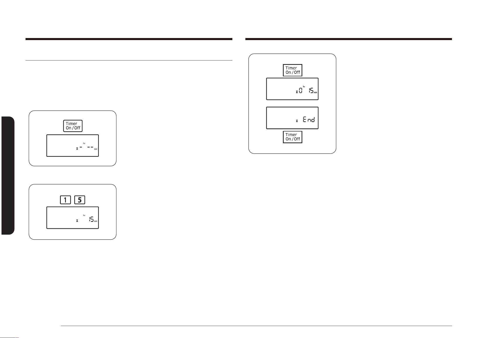
3. Press the Timer On/Off pad to start the
timer.
The display will show the remaining
time. When time has elapsed, the oven
will beep and the display will show End
until you press the Timer On/Off pad.
After the pad is pressed, the display will
go back to showing the time of day.
You can cancel the timer at any time by
pressing the Timer On/Off pad.
Setting the timer on/off
The timer counts down time remaining and beeps when the set time has elapsed.
It does not start or stop cooking functions. You can use the kitchen timer at the
same time as any other range functions and set it for any amount of time between
1 minute and 9 hours and 99 minutes.
How to set the timer
1. Press the Timer On/Off pad once for
hours/minutes and twice for seconds.
Press the pad three times to turn off the
kitchen timer or cancel it before it starts
to run.
The display will show Timer, and
-
hr
--
min
will blink in the display. (Hr and
min characters are not displayed on the
NX58*560***, NX58*751***.)
2. Press the number pads to enter the
amount of time you want in minutes,
hours and minutes, or seconds
(e.g., 1, 5).
The set time will show in the display.
English 35
Operating the oven
Positioning the oven racks
The oven racks are removable and
can be positioned in any of the seven
oven rack positions. Each oven rack
has a built-in stop to prevent it from
accidentally being pulled completely
out. Proper positioning of the oven
racks will provide the best cooking
results. The diagram to the right shows
the rack positions.
5
6
7
4
3
2
1
CAUTION
• Do not cover an oven rack with aluminum foil. This will disturb the heat
circulation, resulting in poor baking.
• Do not place aluminum foil on the oven bottom. It can damage the surface of
the oven bottom.
• Arrange the oven racks only when the oven is cool.
• When placing an oven rack in the topmost rack position (position 7), make sure
the rack is stably situated on the embossed stop.
Oven rack positions
TYPE OF FOOD RACK POSITION
Hamburgers and steaks 6 or 7
Toasts 5 or 6
Biscuits, mufns, brownies, cookies 4
Bundt or pound cakes 3
Angel food cake, pies 2
Roasts (small or large), ham, turkeys 1 or 2
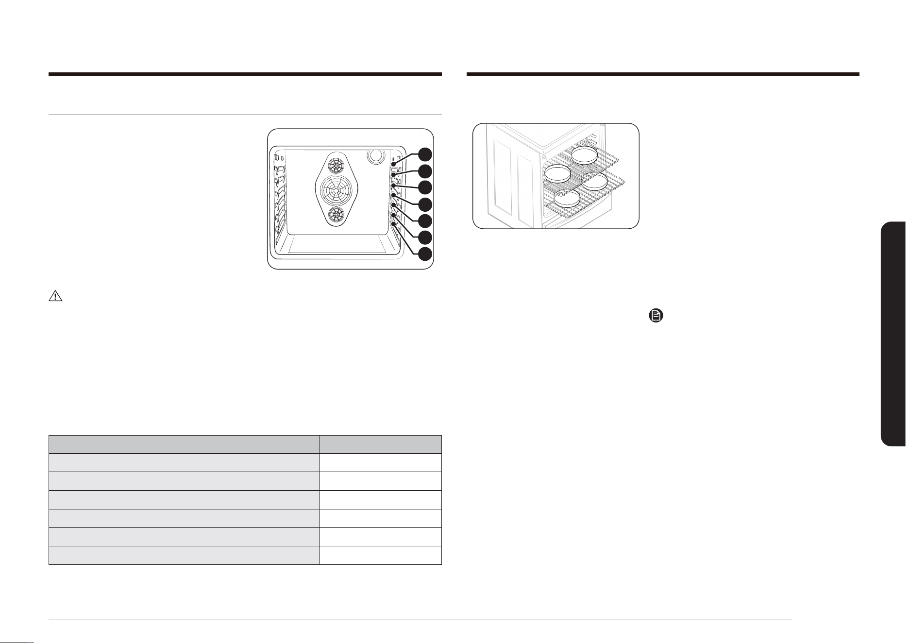
Baking layer cakes
• Centering the baking pans in the oven
will produce better cooking results.
• When baking multiple items, make sure
to leave a 1 to 1.5” (2.5 to 3.8 cm) space
around each item.
• When baking on multiple racks, place
the oven racks in positions 2 and 5.
• When convection baking on multiple
racks, place the oven racks in positions
2 and 5.
• Place two pans in the rear of the top
rack and the other two pans in the front
of the bottom rack.
NOTE
Proper positioning of food items in the
oven will help you achieve the best cooking
results.
36 English
Operating the oven
Operating the oven
Using the gliding rack (NX58*565*** Only)
The fully extendable Gliding Rack makes food preparation easier, especially when
preparing heavier dishes. The Gliding Rack has 2 glide tracks that allow you to
extend the rack with food on it out of the oven for easier access and removal.
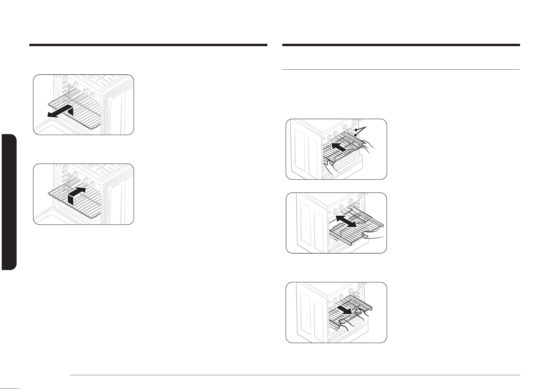
Installing the Gliding rack
Rack
Guides
• With the Gliding rack in the “Closed”
position and the oven off, carefully
insert the Gliding Rack between the
guides until the rack reaches the back.
• When using the Gliding Rack in the
oven, be sure to pull on the handle of
the rack only to slide it in and out. If you
grasp the frame while using the rack,
you can pull the entire Gliding Rack out
of the oven.
Removing the Gliding rack
• With the Sliding rack in the “Closed”
position and the oven off and cool,
grasp the rack and frame and pull both
towards you to remove.
To remove an oven rack:
1. Pull the rack straight out until it stops.
2. Lift the front of the oven rack, and then
pull to remove it from the oven.
To replace an oven rack:
1. Place the back edge of the rack on the
desired rack supports.
2. Lift the front of the rack, and then slide
it into the oven.
English 37
Operating the oven
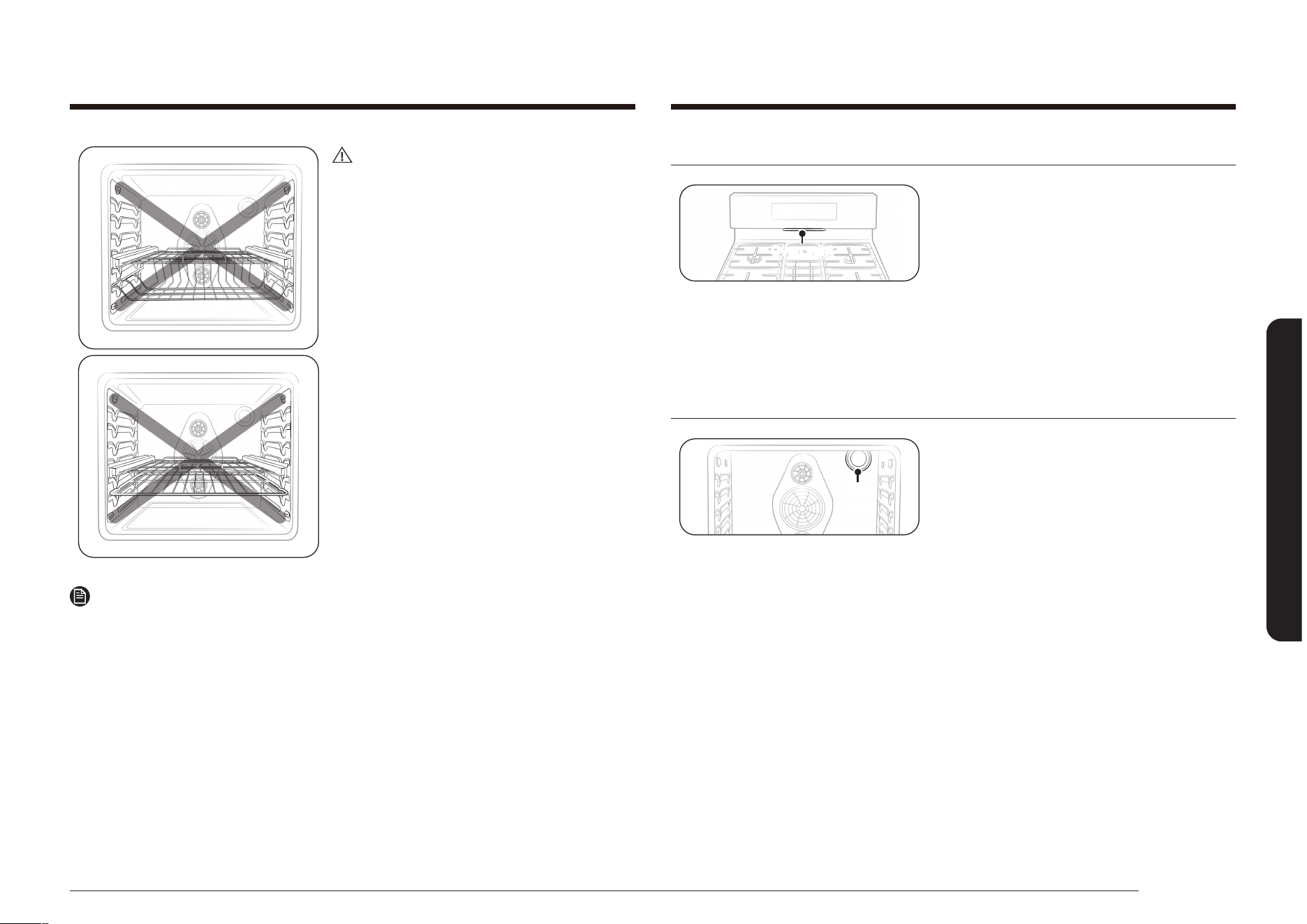
Oven vent
Oven vent
The oven vent is located under the oven
control panel. Do not block or place items in
front of the oven vent. Proper air circulation
prevents oven burner combustion problems
and ensures good cooking results. Since the
vent and area around the vent can become
hot, use care when placing items near the
oven vent. Hot steam could heat or melt
items placed in front of the oven vent.
Oven light
Oven
light
The oven has a light that is located on
the rear oven wall in the upper right-rear
corner. The light can be turned on or off by
touching the Oven Light pad on the oven
control panel. The oven light allows you to
check cooking progress without opening the
oven door. Always use a 40-watt appliance
bulb when replacing the oven light.
See page 67 for light-changing instructions.
CAUTION
Do not install the Gliding rack directly
above the Flat rack and Recessed rack.
You will not be able to install it properly
and the rack could fall.
NOTE
You can install the Gliding rack in any rack positions except the highest (level 7)
and lowest (level 1) rack position in the oven.
38 English
Operating the oven
Operating the oven
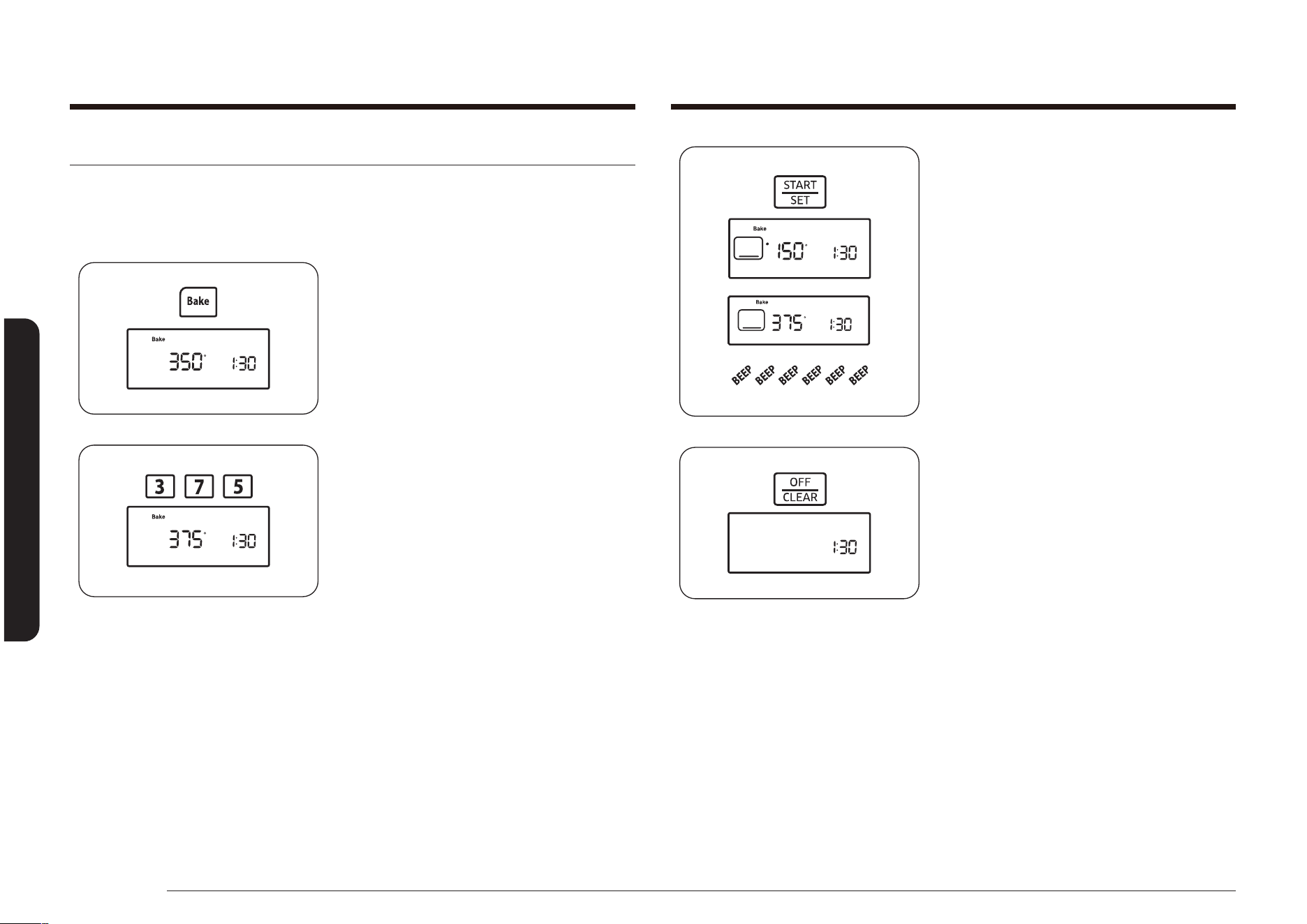
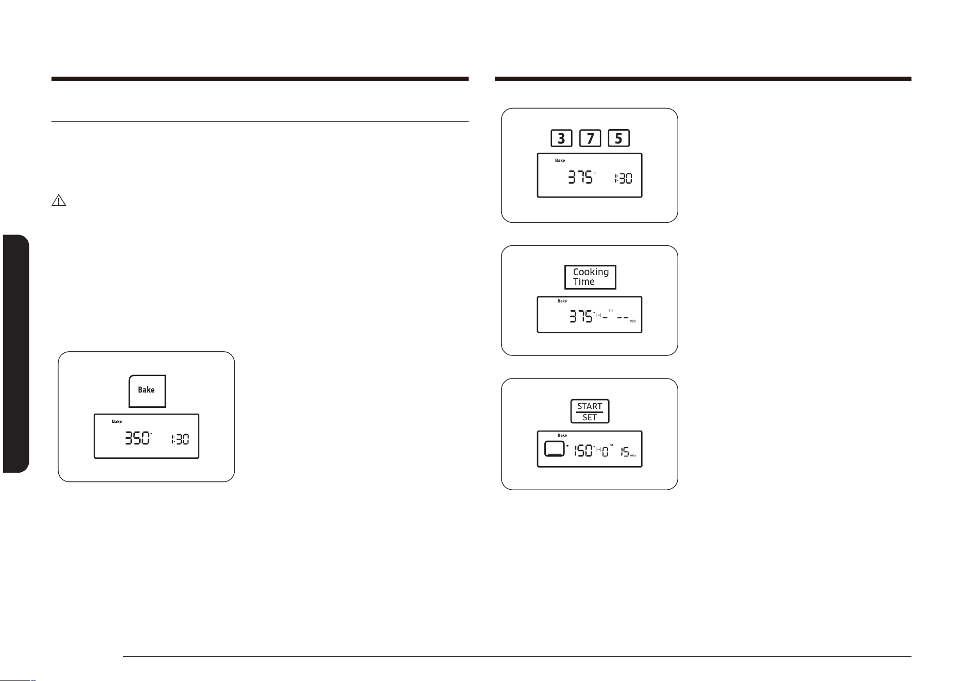
Press the START/SET pad.
The oven will automatically light and
start preheating. The display will show a
blinking “•”, along with 150°, Bake, and
the bake element icon, until the oven
reaches 150°. Then, the display will just
show the actual oven temperature.
When the oven reaches the desired
baking temperature, it will beep 6 times.
4. Place the food in the oven, and then
close the oven door. Preheating is very
important for good baking results.
5. When baking is complete, remove the
item(s) from the oven, close the oven
door, and then press the OFF/CLEAR
pad.
The oven will shut off, and the display
will show the time of day.
To change a programmed baking temperature, press the Bake pad, enter the new
baking temperature, and then press the START/SET pad. If the oven temperature
is higher than the new setting, the oven will beep 6 times, then show the new
setting. The oven will complete cooking at the new temperature.
Baking
The Bake function lets you program the oven to bake at any temperature between
150 °F (66 °C) and 550 °F (288 °C).
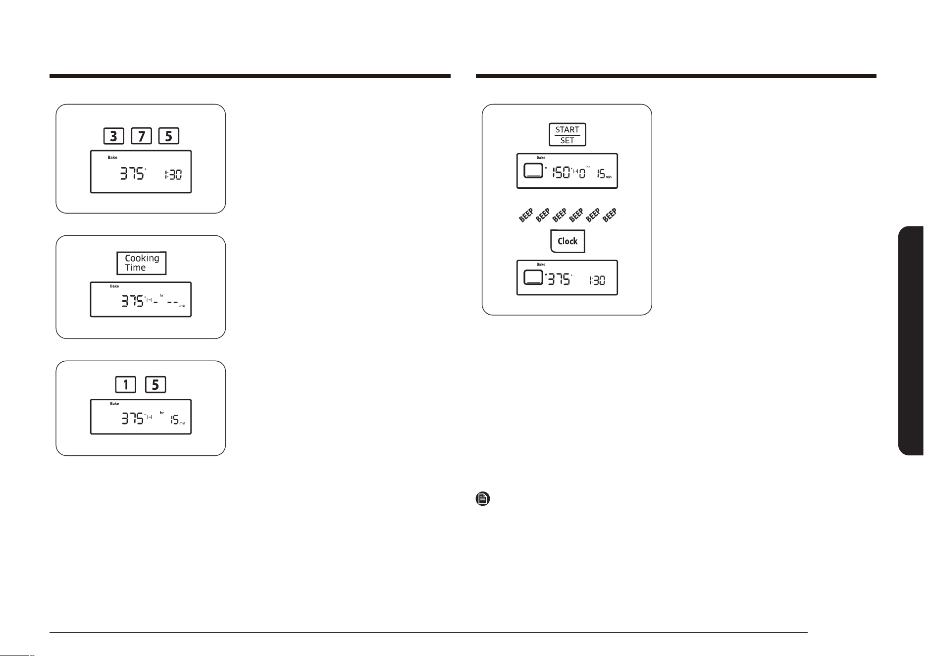
How to set the oven temperature
1. Position the oven rack in the desired
location.
2. Press the Bake pad. The oven will beep
every time a pad is pressed.
The default temperature, 350°, and the
Start indicator will blink on the display.
If the default temperature is the desired
cooking temperature, skip to step 4.
3. Press the number pads to enter the
desired cooking temperature (for
example, 3, 7, 5).
The selected cooking temperature and
the Start indicator will blink on the
display.
English 39
Operating the oven
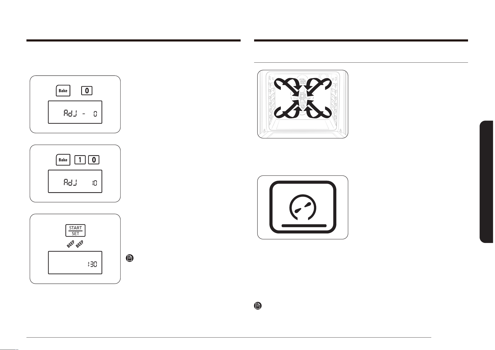
Convection baking and roasting
The Convection Bake function lets
you program the oven to bake at any
temperature between 150 °F (66 °C) and
550 °F (288 °C). The Convection Roast
function lets you program the oven to roast
at any temperature between 150 °F (66 °C)
and 550 °F (288 °C). The convection fan in
the back of the oven cavity circulates the
hot air evenly throughout the oven cavity.
As a result, foods are evenly cooked and
browned in less time than with regular heat.
Convection baking
• Ideal for foods being cooked on multiple
racks.
• Good for large quantities of baked
foods.
• Provides good results with cookies,
biscuits, brownies, cupcakes, cream
puffs, sweet rolls, angel food cake, and
bread.
• Cookies have best cooking results when
cooked on at cookie sheets.
• When convection baking on a single
rack, place the oven rack in position
3 or 4.
When convection baking on multiple
racks, place the oven racks in position
2 and 5.
NOTE
The oven automatically adjusts the temperature for convection baking with the
Convection Auto Conversion feature. See page 57 for details.
If your baking results are not what you are used to, the preset oven
cooking temperature can be adjusted ±30 °F (±15 °C) as follows:
1. Press and hold the Bake and 0 pads for
3 seconds.
The display will show AdJ and 0.
2. Press the Bake pad to toggle between
+ or – temperature adjustments.
3. Press the number pads to enter the
desired temperature adjustment (for
example, 1, 0).
The display will show AdJ and 10.
4. Press the START/SET pad.
The oven will beep twice, and the
display will show the time of day. The
next time you bake, the oven will use
the new temperature setting.
NOTE
This adjustment will not affect the broiling
or the self-cleaning temperatures. The
adjustment will be retained in memory after
a power failure.
40 English
Operating the oven
Operating the oven
How to set the oven for convection baking or roasting
1. Position the oven rack in the desired
location.
2. Press the Convection Bake ( )
or Convection Roast ( ) pad. The
oven will beep every time a pad is
pressed.
The default temperature, 350°, will
blink on the display. If the default
temperature is the desired cooking
temperature, skip to step 4.
3. Press the number pads to enter the
desired cooking temperature (for
example, 4, 2, 5).
The selected cooking temperature will
blink on the display.
Convection roasting
• Good for larger tender cuts of meat,
uncovered.
• Place a broil pan and grid under the
meat or poultry during convection roast
for best results. The pan catches grease
spills and the grid prevents grease
spatters.
Meat and poultry are browned on all sides as if they were cooked on a rotisserie.
Heated air will be circulated over, under, and around the food being roasted. The
heated air seals in juices quickly for a moist and tender interior while creating a
rich, golden-brown exterior.
See the Convection roasting guide on page 41 for recommended cooking times
and temperatures.
English 41
Operating the oven
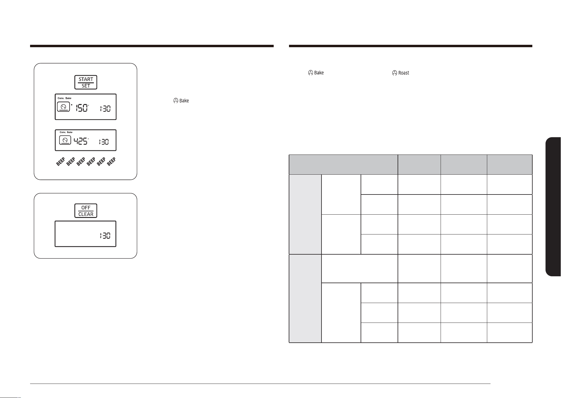
Press the START/SET pad.
The oven will automatically light and
start preheating. The display will show
a blinking “•”, along with 150°, Conv.
Bake ( ), and the convection bake
element and fan icons, until the oven
reaches 150°. Then, the display will just
show the actual oven temperature.
When the oven reaches the desired
baking or roasting temperature, it will
beep 6 times.
4. Place the food in the oven, and then
close the oven door.
Preheating is very important for good
baking results. All roasting should be
done on a broil pan and grid.
5. When baking or roasting is complete,
remove the item(s) from the oven, close
the oven door, and press the OFF/CLEAR
pad.
The oven will shut off, and the display
will show the time of day.
To change a programmed baking or roasting temperature, press the Convection
Bake ( ) or Convection Roast ( ) pad, enter the new cooking
temperature, and then press the START/SET pad.
If the oven temperature is above the new setting, the oven will beep 6 times, then
show the new setting. The oven will complete cooking at the new temperature.
Convection roasting guide
The size, weight, thickness, roasting temperature setting, and your preference of
doneness will affect the roasting time.
The following guide is based on foods starting at refrigerator temperature.
Food
Minutes Per
Pound
Oven
Temperature
Internal
Temperature
Beef
Rib Roast
(3 to 5 lb)
Medium 28–33
350 °F
(177 °C)
160 °F
(71 °C)
Well Done 30–38
350 °F
(177 °C)
170 °F
(77 °C)
Tenderloin
Roast
(2 to 3 lb)
Medium 35–45
350 °F
(177 °C)
160 °F
(71 °C)
Well Done 45–55
350 °F
(177 °C)
170 °F
(77 °C)
Pork
Roast
(Bone-in or Boneless)
(3 to 5 lb)
22–28
350 °F
(177 °C)
170 °F
(77 °C)
Chops
(0.5- to
1” thick)
2 chops 30–40 total
350 °F
(177 °C)
170 °F
(77 °C)
4 chops 40–50 total
350 °F
(177 °C)
170 °F
(77 °C)
6 chops 45–55 total
350 °F
(177 °C)
170 °F
(77 °C)
42 English
Operating the oven
Operating the oven
Timed cooking
The Cook Time function lets you program the oven to cook food at a set
temperature for a desired length of time. At the end of the set time, the oven will
automatically shut off.
CAUTION
Use caution when using the Cooking Time or Delay Start functions. These functions
are best used when cooking cured or frozen meats and most fruits and vegetables.
Foods that can easily spoil, like milk, eggs, sh, poultry, and meats, should be
chilled in a refrigerator before they are placed in the oven. Even when chilled,
they should not stand for more than 1 hour before cooking begins and should be
removed promptly when cooking is completed. Eating spoiled food can result in
sickness from food poisoning.
How to set the oven for timed cooking
1. Position the oven rack in the desired
location. Place the food in the oven, and
then close the oven door.
2. Press the Bake pad.
The default temperature, 350°, will
blink on the display. If the default
temperature is the desired cooking
temperature, skip to step 4.
Food
Minutes Per
Pound
Oven
Temperature
Internal
Temperature
Poultry
Chicken, Whole
(2.5 to 3.5 lb)
26–30
375 °F
(191 °C)
180 °F
(82 °C)
Turkey, Whole
(Unstuffed *)
(10 to 16 lb)
10–16
325 °F
(163 °C)
180 °F
(82 °C)
Turkey, Whole
(Unstuffed *)
(18 to 24 lb)
8–15
325 °F
(163 °C)
180 °F
(82 °C)
Turkey Breasts
(4 to 6 lb)
18–23
325 °F
(163 °C)
170 °F
(77 °C)
Cornish Hen
(1 to 1.5 lb)
50–75 total
325 °F
(163 °C)
180 °F
(82 °C)
Lamb
Half Leg
(3 to 4 lb)
Medium 25–30
325 °F
(163 °C)
160 °F
(71 °C)
Well Done 30–35
325 °F
(163 °C)
170 °F
(77 °C)
Whole Leg
(6 to 7 lb)
Medium 25–30
325 °F
(163 °C)
160 °F
(71 °C)
Well Done 30–35
325 °F
(163 °C)
170 °F
(77 °C)
NOTE
* Stuffed turkey requires additional roasting time. The minimum safe temperature
for stufng in poultry is 165 °F (74 °C).
English 43
Operating the oven
Press the START/SET pad.
The oven will automatically light and
start preheating. The display will show
a blinking “•” along with the default
or selected temperature, Bake, and
the bake element icon, until the oven
reaches that temperature.
When the oven reaches the desired
temperature, it will beep 6 times. The
oven will start cooking for the set
amount of time, and the remaining
cooking time will be displayed.
To see the time of day, press and hold
the Clock pad. When the Clock pad is
released, the display will go back to
the remaining cooking time. When the
cooking time has elapsed, the oven will
automatically shut off and the display
will show the time of day.
To change a programmed baking temperature, press the Bake pad, enter the new
baking temperature, and press the START/SET pad. If the oven temperature is
above the new setting, the oven will beep 6 times, then show the new setting. The
oven will complete cooking at the new temperature.
To change a programmed cooking time, press the Cooking Time pad, enter the
new cooking time, and then press the START/SET pad. The oven will continue
cooking for the remaining new set time.
NOTE
Place food in the oven after preheating if the recipe calls for it. Preheating is
important for good baking results. After the oven has reached the desired cooking
temperature, it will beep 6 times.
3. Press the number pads to enter the
desired cooking temperature
(for example, 3, 7, 5).
The selected cooking temperature will
blink on the display.
4. Press the Cooking Time pad.
The display will show -
hr
--
min
.
(hr, min characters are not displayed on
the NX58*560***, NX58*751***)
5. Press the number pads to enter the
desired cooking time.
The display will show the selected
time, and the Start indicator will blink.
You can set the time to any duration
between 1 minute and 9 hours and 99
minutes.
44 English
Operating the oven
Operating the oven
3. Press the number pads to enter the
desired cooking temperature (for
example, 3, 7, 5).
The selected cooking temperature and
the Start indicator will blink on the
display.
4. Press the Cooking Time pad.
The display will show the selected
cooking temperature, Bake, and -
hr
--
min
.
(HR, min characters are not displayed on
the NX58*560***, NX58*751***)
5. Press the number pads to enter the
desired cooking time.
The display will show the selected
cooking time, and the Start indicator
will blink. You can set the time to any
amount of time between 1 minute and 9
hours and 99 minutes.
Delay timed cooking
The Delay Start function lets you use the kitchen timer to automatically start and
stop another cooking program (Bake, Convection Bake, or Convection Roast). Delay
Start can be set before other cooking operations by up to 12 hours. The clock must
be set to the correct time of day for Delay Start to work properly.
CAUTION
Use caution when using the Cooking Time or Delay Start functions. These functions
are best used when cooking cured or frozen meats and most fruits and vegetables.
Foods that can easily spoil, like milk, eggs, sh, poultry, and meats, should be
chilled in a refrigerator before they are placed in the oven. Even when chilled,
they should not stand for more than 1 hour before cooking begins and should be
removed promptly when cooking is completed. Eating spoiled food can result in
sickness from food poisoning.
How to set the oven for delay timed cooking
1. Position the oven rack in the desired
location. Place the food in the oven, and
then close the oven door.
2. Press the pad for the desired cooking
operation, e.g., Bake.
The default temperature, 350°, and the
Start indicator will blink on the display.
If the default temperature is the desired
cooking temperature, skip to step 4.

English 45
Operating the oven
To change a programmed starting time, press the Delay Start pad, enter the new
starting time, and then press the START/SET pad. The oven will start cooking at
the new start time.
To change a programmed baking temperature, press the Bake pad, enter the new
baking temperature, and then press the START/SET pad. If the oven temperature is
above the new setting, the oven will beep 6 times, then show the new setting. The
oven will complete cooking at the new temperature.
To change a programmed cooking time, press the Cooking Time pad, enter the
new cooking time, and then press the START/SET pad. The oven will continue
cooking for the remaining new set time.
NOTE
Place food in the oven after preheating if the recipe calls for it. Preheating is
important for good baking results. After the oven has reached the desired cooking
temperature, it will beep 6 times.
6. Press the Delay Start pad.
The display will show Delay, and -- --
will blink.
7. Press the number pads to enter the
time you want the oven to turn on (for
example, 4, 3, 0).
The Start indicator will blink under
Delay and the selected start time.
8. Press the START/SET pad.
The oven will automatically turn on and
beep when the set start time is reached.
The oven will automatically light and
start preheating. When the oven reaches
the desired cooking temperature, it will
beep 6 times.
The display will count down the set
cooking time.
When the cooking time has elapsed, the
oven will automatically shut off and the
display will show the time of day.
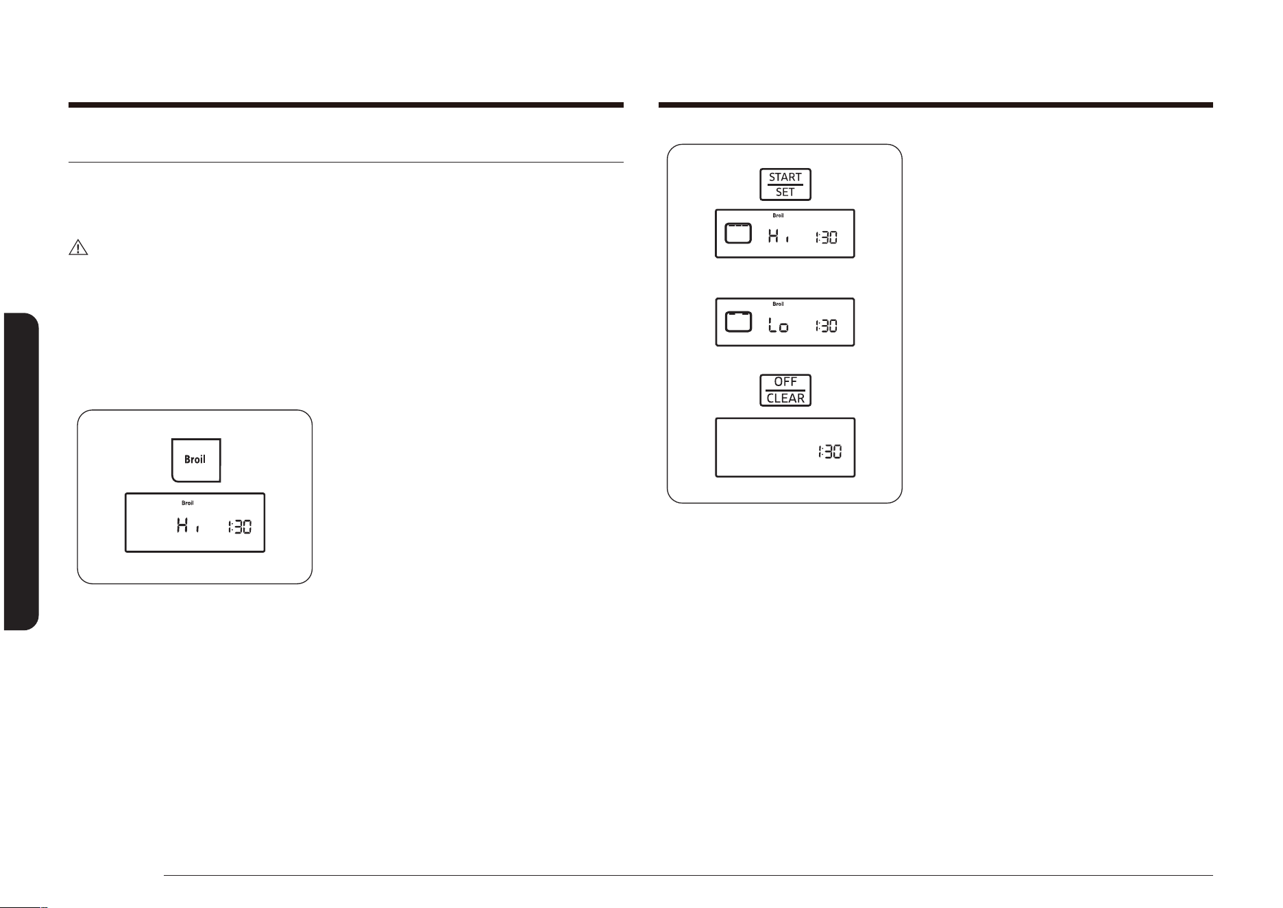
46 English
Operating the oven
Operating the oven
3. Press the START/SET pad.
The oven will automatically light the top
oven burner and start cooking.
The display will show the selected broil
setting (Hi or Lo), the broil element icon,
and Broil.
Broil on one side until food is browned;
turn and cook on the other side.
When cooking is completed, press the
OFF/CLEAR pad to shut off the oven
or to cancel broiling at any time. The
display will show the time of day.
To change a programmed broiling setting, press the Broil pad to toggle the setting
between Hi and Lo. Press the START/SET pad to complete cooking at the new
setting.
Broiling
The Broil function allows you to cook and brown foods using only a top heat
source. The oven door must remain closed during broiling. The meat or sh should
always be placed on a broiling grid in a broiling pan.
CAUTION
If a re occurs during broiling, leave the oven door closed and turn off the
oven. If the re continues, throw baking soda on the re or use a foam-type re
extinguisher. Do not throw water or our on the re. Flour may explode and water
can cause a grease re to spread. Both can cause personal injury and/or property
damage.
How to set the oven for broiling
1. Place the food on a broiling pan with
insert grid. Place the food and pan
on the top oven rack, positioned as
recommended in the Broiling guide on
page 47. Close the oven door.
2. Press the Broil pad once for Hi and
twice for Lo. The oven will beep every
time a pad is pressed.
The Start indicator will blink to the right
of Hi or Lo and Broil on the display.
Use Lo to cook foods such as poultry or
thick cuts of meat thoroughly without
overbrowning them.
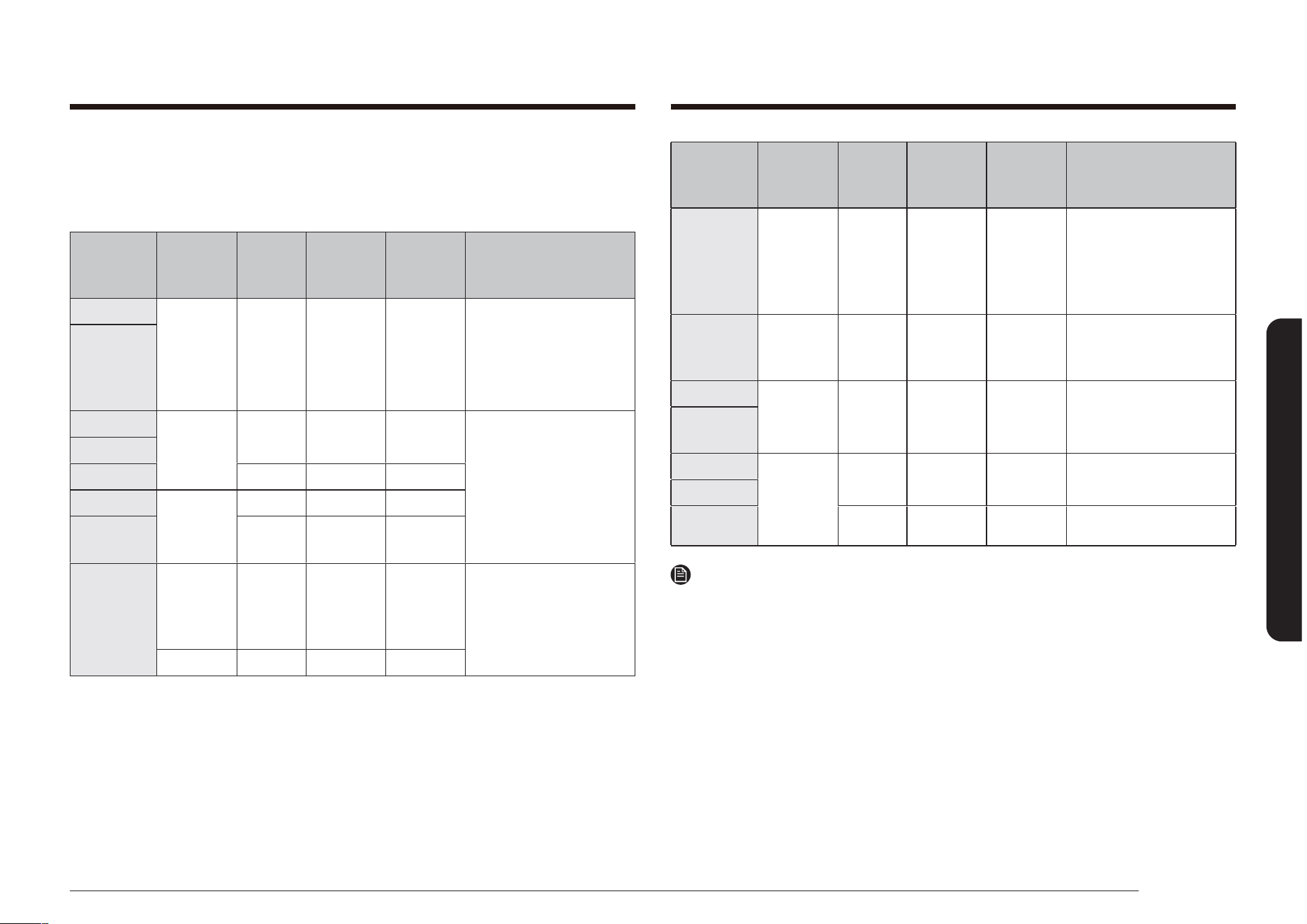
English 47
Operating the oven
Food
Quantity
and/or
Thickness
Rack
position*
1st side
time (min.)
2nd side
time (min.)
Comments
Fish Fillets
0.25- to
0.5” thick
6 6-10 3-4
Handle and turn very
carefully.
Brush with lemon butter
before and during cooking,
if desired.
Ham Slices
(precooked)
0.5” thick 6 7-10 5-6
Increase time 5 to 10
minutes per side for 1.5”
thick or home-cured ham.
Pork Chops
Well Done
2 (0.5”
thick)
6 8-11 4-6 Slash fat.
Lamb Chops
Medium 2 (1” thick)
about 10 to
12 oz
6 8-12 5-8 -
Well Done 6 10-16 7-11 Slash fat.
NOTE
* See illustration on page 35 for description of rack positions.
Broiling guide
The size, weight, thickness, broiling temperature setting, and your preference of
doneness will affect the broiling time. The following guide is based on meats and/
or sh starting at refrigerator temperature.
Food
Quantity
and/or
Thickness
Rack
position*
1st side
time (min.)
2nd side
time (min.)
Comments
Ground Beef
Well Done
1 lb
(4 patties)
0.5- to
0.75” thick
6 or 7 7-10 5-7
Space evenly. Up to 8
patties may be broiled at
once.
Beef Steaks
Medium
1” thick 1
to 1.5 lbs
6 10-12 5-7 Steaks less than 1” thick
cook through before
browning.
Pan frying is
recommended.
Slash fat.
Well Done 6 12-14 6-8
Medium
1.5” thick 2
to 2.5 lbs
6 15-18 14-17
Well Done 6 18-22 17-19
Chicken
1 whole
cut-up 2 to
2.5 lbs Split
lengthwise
4 30-35 15-20
Broil skin-side-down rst.
Spread open.
Brush with melted butter
before and halfway
through broiling.
2 breasts 5 15-20 7-12
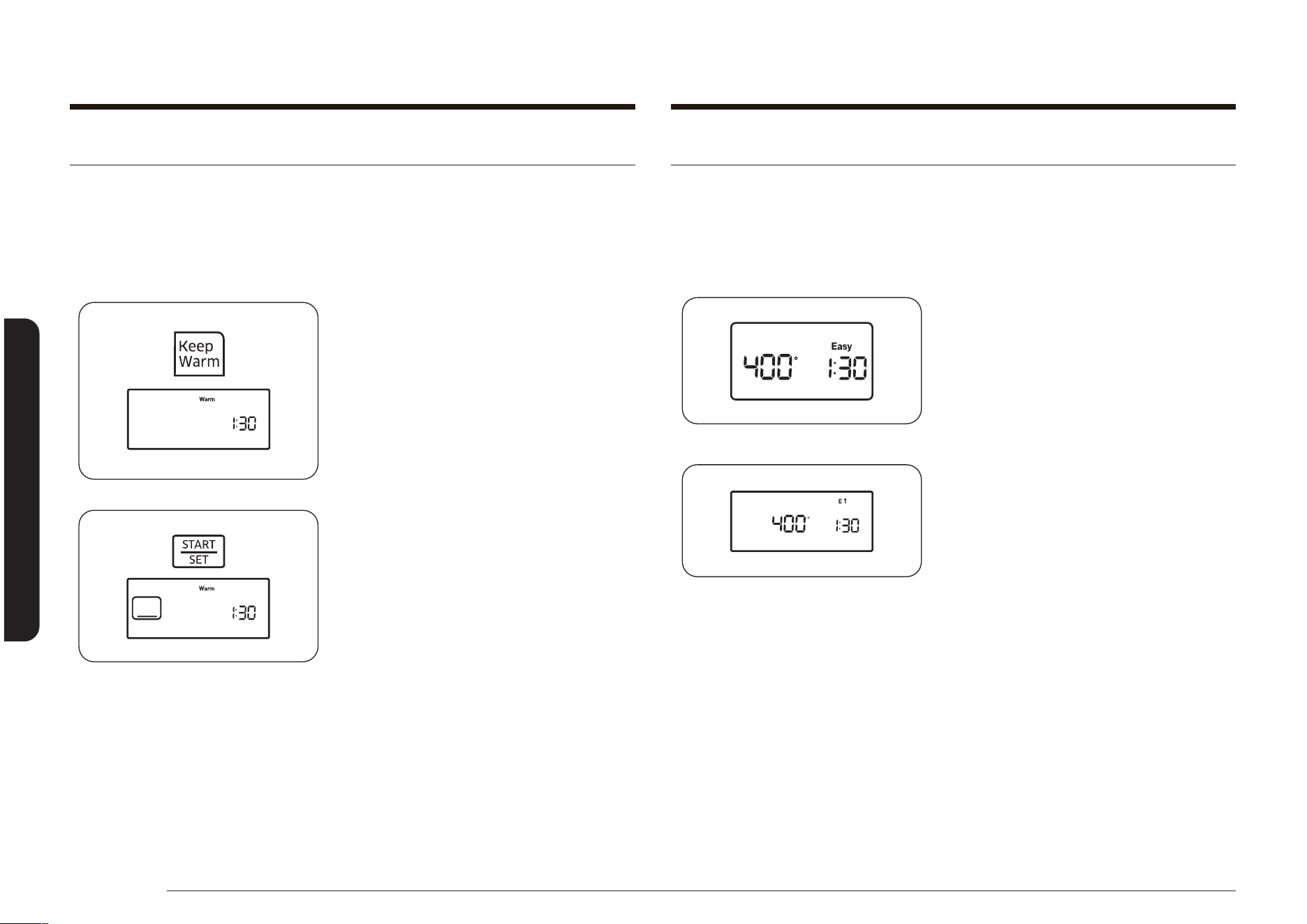
48 English
Operating the oven
Operating the oven
Using the easy cook feature
Pizza
The pizza function is designed to produce a crisp and browned bottom while
keeping the topping moist.
How to set the Pizza function
NX58*560***, NX58*751***
NX58*565***
1. Press the Pizza pad.
Keep warm
The Keep Warm function allows you to keep cooked foods warm at a low baking
temperature. The Keep Warm feature keeps cooked food warm for serving up to 3
hours after cooking has nished. After 3 hours, the feature automatically shuts off
the oven.
How to use the keep warm feature
1. Position the oven rack in the desired
location. Place the food in the oven and
close the oven door.
2. Press the Keep Warm pad.
The Start indicator will blink under the
time of day and Warm appears on the
display.
3. Press the START/SET pad.
The oven will automatically light and
start preheating to the Keep Warm
temperature (approx. 170 °F [77 °C]).
The display will show the oven element
icon, Warm, and the time of day.
To cancel Keep Warm and shut the
oven off, press the OFF/CLEAR pad. The
display will show the time of day.
To program Keep Warm after a timed cooking function, press the Keep Warm pad
after you program the timed cooking function. When Time Cook is complete, the
oven will beep 6 times and lower the oven temperature to the Keep Warm setting.
The oven will maintain that temperature until Keep Warm is canceled.
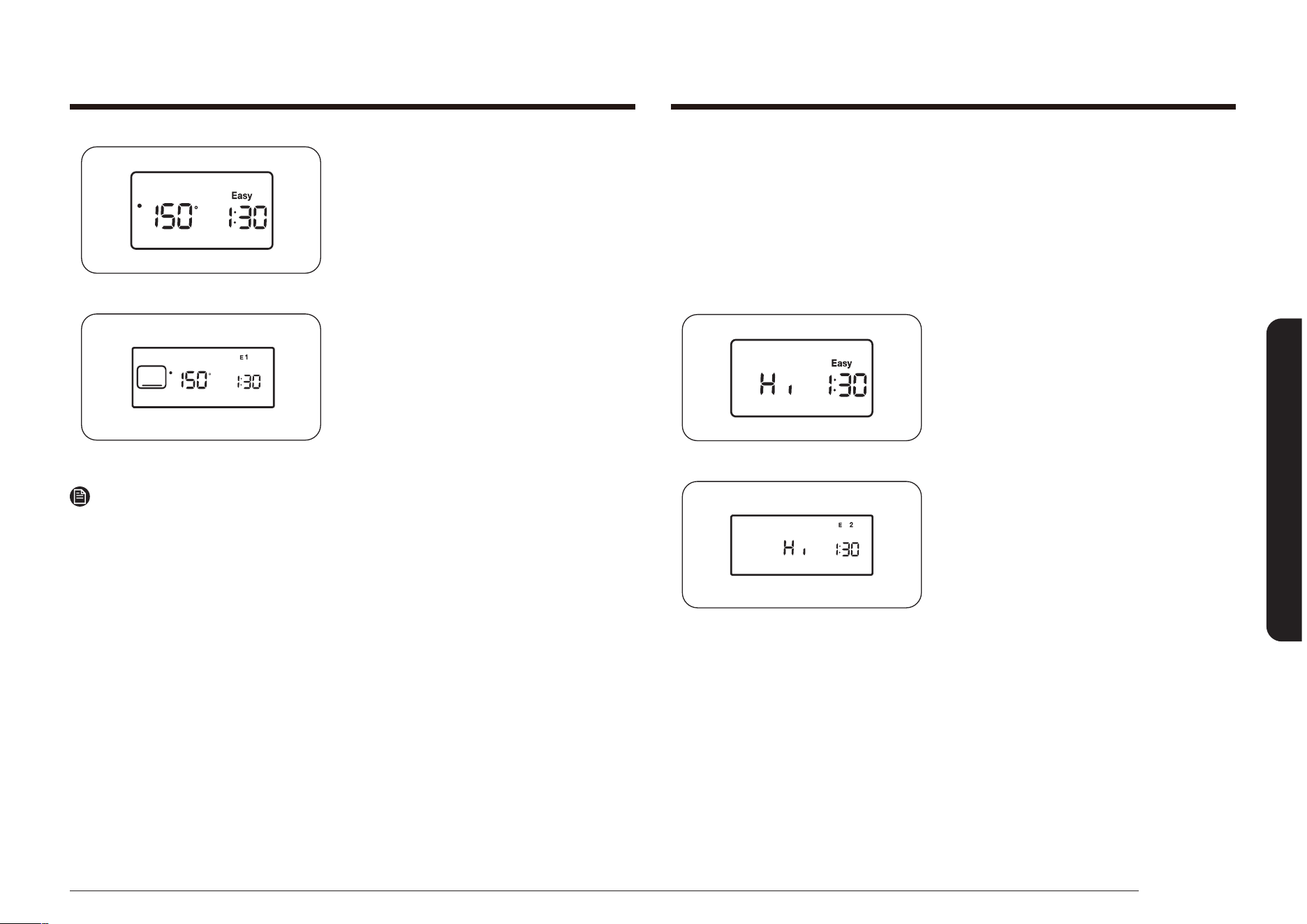
English 49
Operating the oven
Slow Cook
The Slow Cook feature can be used to cook food more slowly at lower oven
temperatures. The extended cooking times allow better distribution of avors
in many recipes. This feature is ideal for roasting beef, pork, and poultry. Slow
cooking meat may cause the exterior of the meat to become dark but nor burnt.
This is normal.
How to set the Slow Cook
NX58*560***, NX58*751***
NX58*565***
1. Press the Slow Cook pad once for HI or
twice for LO.
NX58*560***, NX58*751***
NX58*565***
2. Press the START/SET pad to begin pizza
cooking.
NOTE
• Use only 1 rack and place the rack in position 3 or 4 for the best results when
using the pizza feature.
• The default temperature is 400 °F. You may adjust the oven temperature to t
your needs.
• Follow the package instructions for preheating and baking times.
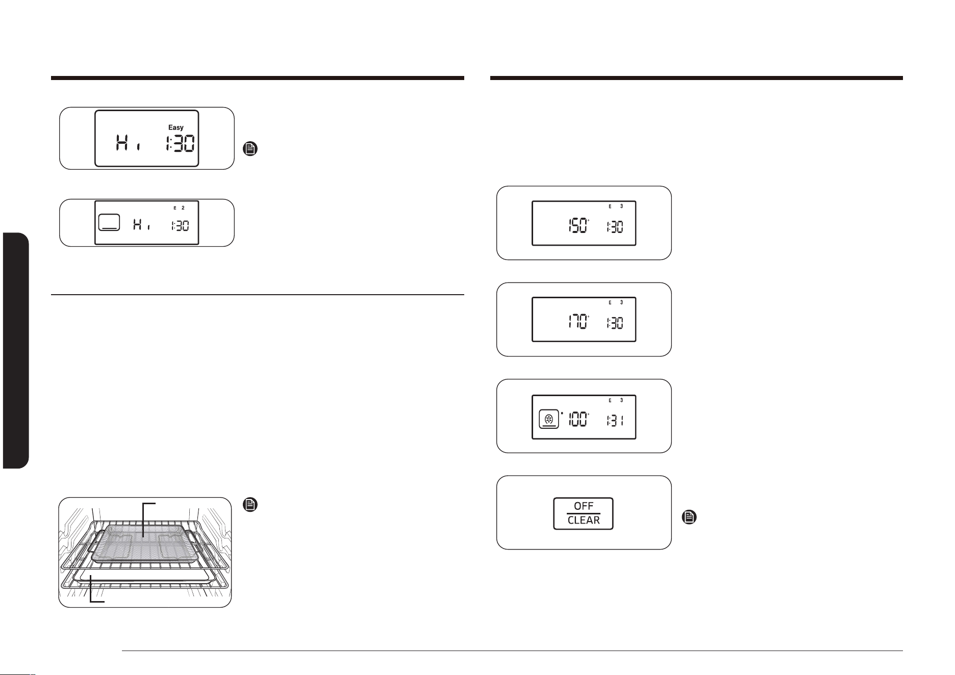
50 English
Operating the oven
Operating the oven
Dehydrate
This function is designed to dry food or remove the moisture from food using heat
circulation.
How to set the Dehydrate function
1. Press the Dehydrate pad.
2. Press the number pads for the desired
temperature.
(set between 100 ˚F and 175 ˚F)
3. Press the START/SET pad to start the
dehydrate mode.
4. When the food is dehydrate, press the
OFF/CLEAR pad.
NOTE
• Do not preheat the oven for this
function.
• After drying the food, keep it in a cool
and dry place.
• If the temperature setting is out of
range, an error will be displayed.
NX58*560***, NX58*751***
NX58*565***
2. Press the START/SET pad to begin slow
cooking.
NOTE
• Use only 1 rack and place the rack in
position 3 or 4 for the best results.
• Preheating the oven will not be
necessary.
Air Fry mode (Model NX58*751***)
This feature uses hot air for crispier and healthier frozen or fresh foods without
or less oil than normal convection modes. For best results, use this mode in single
oven mode and place the Air Fry tray in position 3. The temperature can be set
between 350 °F and 500 °F. Preheating is not necessary for this mode. Follow
recipe or package directions for set temperature, time or quantity.
How to set the oven for Air Fry mode
1. Place the tray on rack position 4.
2. Select Air Fry mode using the touch key.
3. Use the touch key to change the default temperature. Enter the suggested
temperature for your food as recommended by its instructions. The default
temperature is 425 °F.
4. Push the touch key and set the Cook Time or Delay Start, if necessary.
5. Press START/SET pad to start Air Fry mode.
6. When cooking is complete, press OFF/CLEAR pad. take out the food.
Tray or Baking sheet
Air fry tray
Air Fry Tray recommended
placement
NOTE
• Place a baking sheet or tray on the rack
below the Air Fry tray to catch any
drippings. This will help to reduce splatter
and smoke.
• Air Fry is designed for baking on a single
oven rack. Place food on rack position 4
for best results.
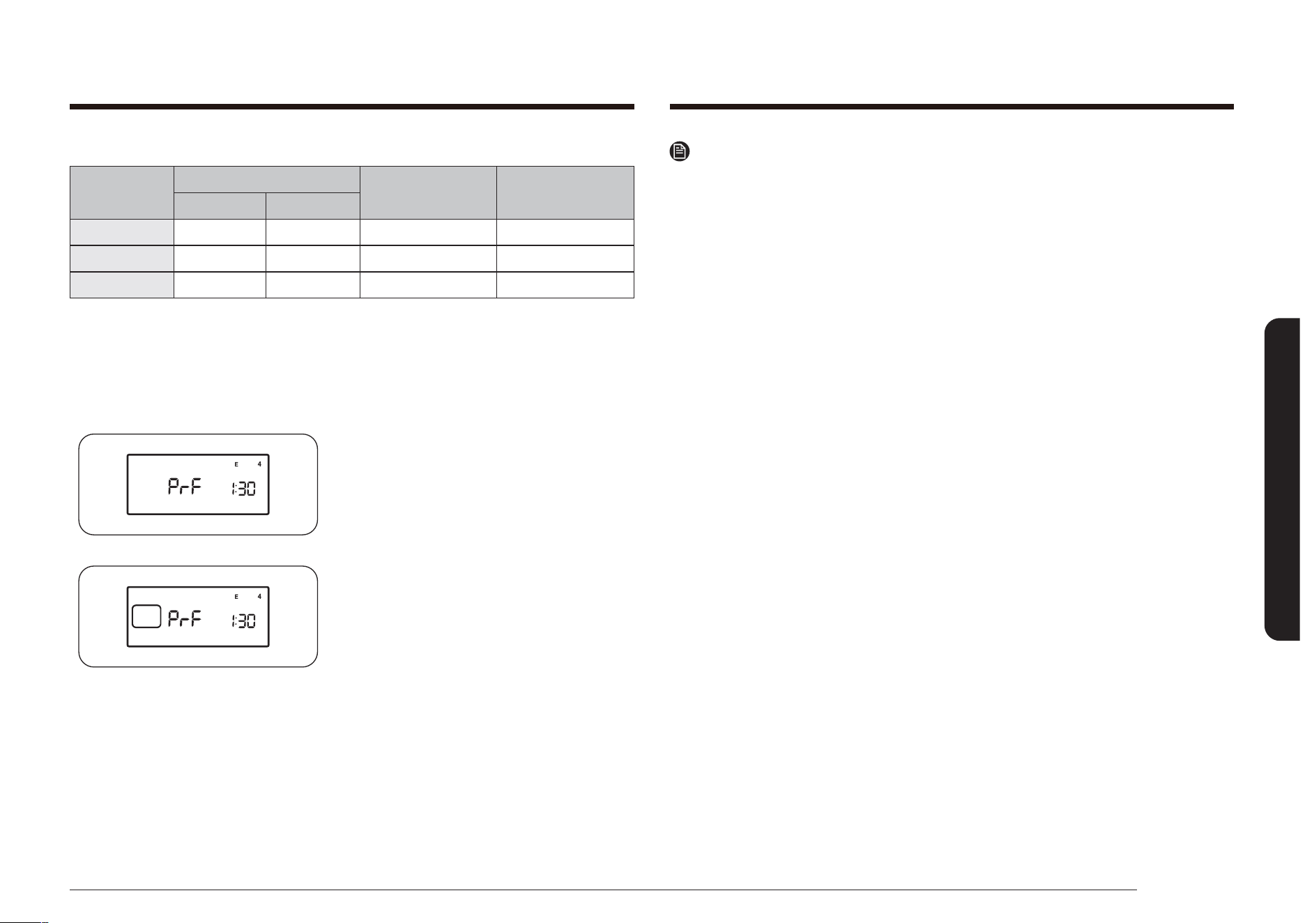
English 51
Operating the oven
NOTE
• If you press the BREAD PROOF pad when the oven temperature is above
100˚F, Hot will appear in the display. Because these functions produce the best
results when started while the oven is cool, we recommend that you wait until
the oven has cooled down and Hot disappears from the display.
• To avoid lowering the oven temperature and lengthening proong time, do not
open the oven door unnecessarily.
• Check bread products early to avoid over-proong.
• Do not use the proong mode for warming food or keeping food hot.
The proong oven temperature is not hot enough to hold foods at safe
temperatures. Use the warm feature.
• For best results, place the dough in a dish in the oven on rack 3 or 4 and
cover the dough with a cloth or with plastic wrap. (The plastic may need to be
anchored underneath the container so the oven fan will not blow it off.)
Dehydrate guide
Category
Rack position
Recommended
weigth (oz)
Optimum temp.
Single rack Multi rack
Vegetables 3 or 4 2 and 5 9 to 21 100-150 ˚F
Fruits 3 or 4 2 and 5 9 to 21 100-150 ˚F
Meats 3 or 4 2 and 5 14 to 30 145-175 ˚F
Bread Proof
The proong feature maintains a warm environment useful for rising yeast-
leavened products.
How to set the oven for proong
1. Enter the proong mode.
Press the Bread Proof pad.
2. Start the proong function. Press the
pad. The proong feature automatically
provides the optimum temperature for
the proof process, and therefore does
not have a temperature adjustment.
3. Press the OFF/CLEAR pad at any time to
turn off the proong feature.

52 English
Operating the oven
Operating the oven
3. Press the Favorite Cook pad once to
store these settings under Recipe 1,
twice to store them under Recipe 2, or
three times for Recipe 3.
The corresponding number and the
setting will show on the display, and
Favorite Cook will blink under the
selected Favorite Cook setting for that
recipe.
4. Press the START/SET pad.
The display will show the last set or
used Favorite Cook temperature setting
and the current time of day.
NOTE
Press the START/SET pad once to save the
Favorite Cook setting or twice to save and
start Favorite Cook at the selected setting.
Favorite cooking
The Favorite Cook function allows you to preprogram up to 3 different cooking
functions or favorite recipe settings so they can be recalled and started at a touch
of a button. You can use only Bake, Convection Bake, or Roast Convection as a
Favorite Cook selection. You can not use any Delay Start functions as a Favorite
Cook selection.
How to set a favorite cook selection
1. Press the pad for the cooking operation
you want to store, e.g., Bake. The oven
will beep every time a pad is pressed.
The default temperature 350° will
blink on the display. If the default
temperature is the desired cooking
temperature, skip to step 3.
2. Press the number pads to enter the
desired cooking temperature (for
example, 3, 7, 5).
The selected cooking temperature will
blink on the display.
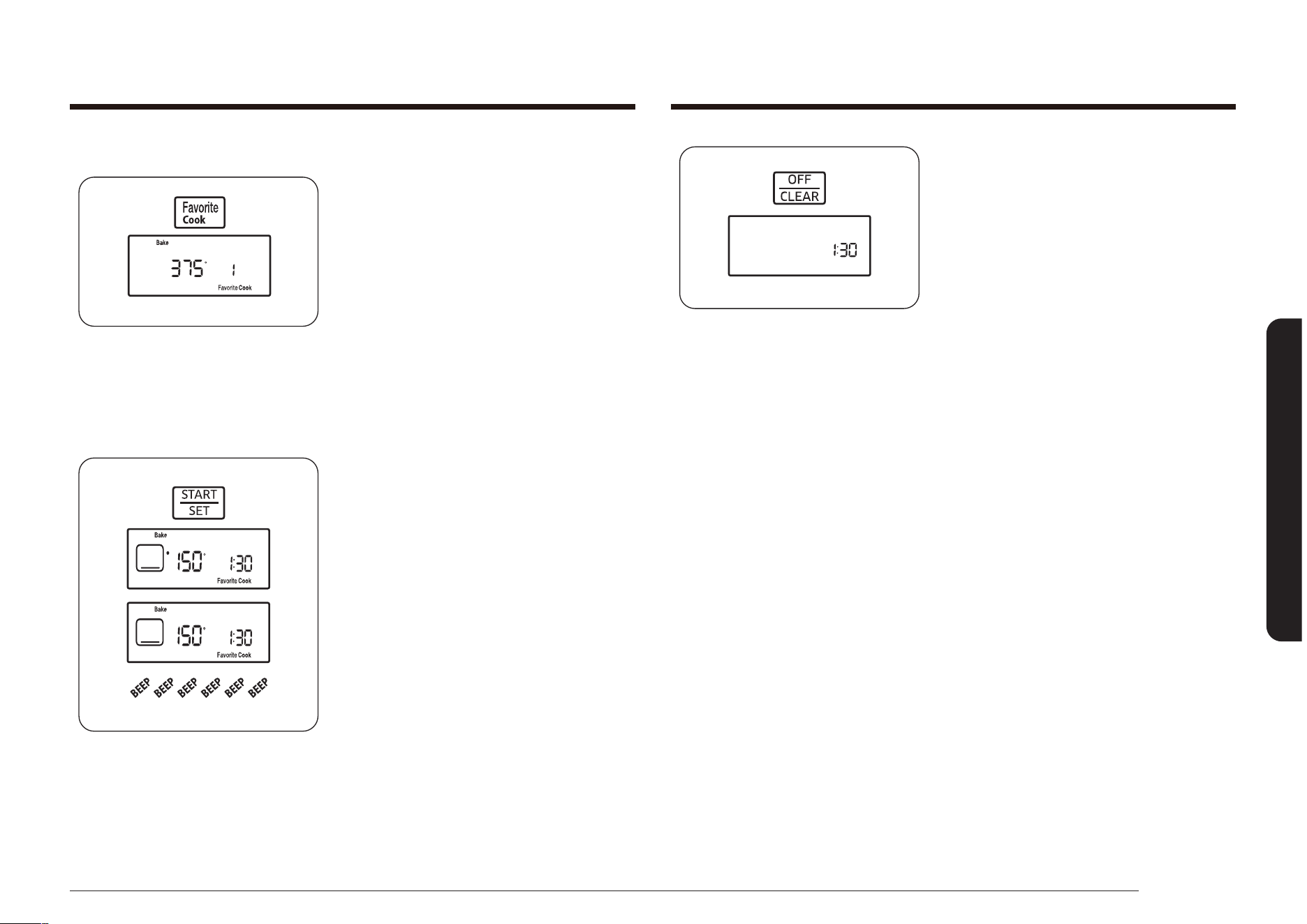
English 53
Operating the oven
4. Place the food in the oven and close the
oven door. Preheating is very important
for good baking or roasting results.
5. When cooking is complete, remove the
item(s) from the oven, close the oven
door, and press the OFF/CLEAR pad.
The oven will shut off and the display
will show the time of day.
How to use or recall a favorite cook selection
1. Position the oven rack in the desired
location.
2. Press the Favorite Cook pad. To recall
the Favorite Cook setting you want from
its storage location, press the Favorite
Cook pad as shown below:
1 time for Recipe 1,
2 times for Recipe 2,
3 times for Recipe 3.
Favorite Cook will blink under the
selected Favorite Cook setting on the
display for that recipe.
3. Press the START/SET pad.
A “•” will blink to the left of the default
or actual temperature until the selected
temperature is reached. The oven will
beep 6 times. The default or actual
temperature, the cooking function, the
cooking function icon, and the time of
day will be displayed.
When the oven reaches the desired
cooking temperature, it will beep 6
times.
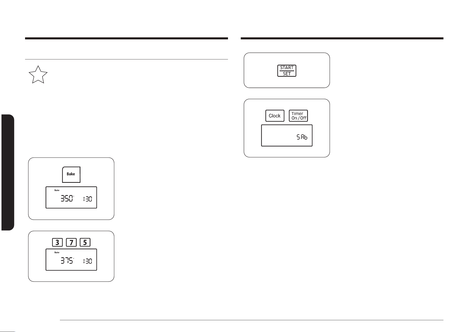
54 English
Operating the oven
Operating the oven
4. Press the START/SET pad.
5. Press and hold the Clock and Timer On/
Off pad at the same time for 3 seconds.
The display will show SAb. The oven
signals, display LEDs, and all oven
controls except the number, Bake,
Cooking Time, START/SET, and OFF/
CLEAR pads will be deactivated.
In approximately 20 seconds, the
control panel will “click” and the oven
will start the lighting and preheating
process. After the oven reaches the
selected cooking temperature, the
oven will continue to cook at that
temperature until the Cook Time has
elapsed or the Sabbath function is
cancelled.
The display will not count down the set
cook time, but the oven will shut off at
the end of the set time.
Sabbath function
K
(For use on the Jewish Sabbath and Holidays)
For further assistance, guidelines for proper usage and a complete list
of models with the Sabbath feature, please visit the web at
http:\\www.star-k.org.
The Sabbath function can only be used with the Bake and Cooking Time settings.
The oven will operate at the set temperature and stay on until the Sabbath
function is cancelled or the set Cooking Time has elapsed. When Sabbath is
selected, it overrides the preset factory energy-saving features. All display
lighting, oven signals, most control pads, and the convection fan will be
deactivated.
How to set the Sabbath function
1. Position the oven rack in the desired
location. See page 35.
2. Press the Bake pad. The oven will beep
every time a pad is pressed until the
Sabbath function is activated.
The default temperature, 350°, will
blink on the display. If the default
temperature is the desired cooking
temperature, skip to step 4.
3. Press the number pads to enter the
desired cooking temperature
(for example, 3, 7, 5).
The selected cooking temperature will
blink on the display.
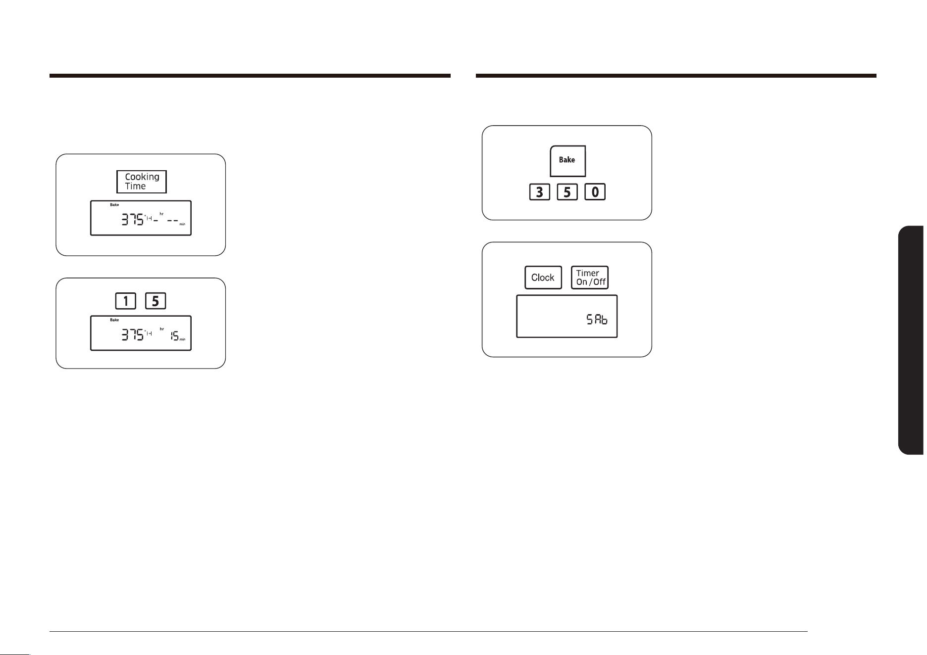
English 55
Operating the oven
How to change the temperature and exit the Sabbath function
To change a programmed baking
temperature, press the Bake pad, enter the
new baking temperature, and then press
the START/SET pad. In approximately 20
seconds, the control panel will “click” and
the oven will complete cooking at the new
temperature.
To exit the Sabbath function, press and hold
the Clock and Timer On/Off pad at the same
time for 3 seconds. The display will show
the time of day.
How to set timed bake in Sabbath mode
To set timed bake in Sabbath mode, follow steps 1 through 3 from How to set the
Sabbath function, and then follow the steps below.
1. Press the Cooking Time pad.
The display will show -
hr
--
min
.
(Hr and min characters are not displayed
on the NX58*560***, NX58*751***.)
2. Press the number pads to enter the
desired cooking time.
The START indicator will blink on the
display. You can set the time to any
length of time between 1 minute and 9
hours and 99 minutes.
Proceed to step 4 from How to set the
Sabbath function.
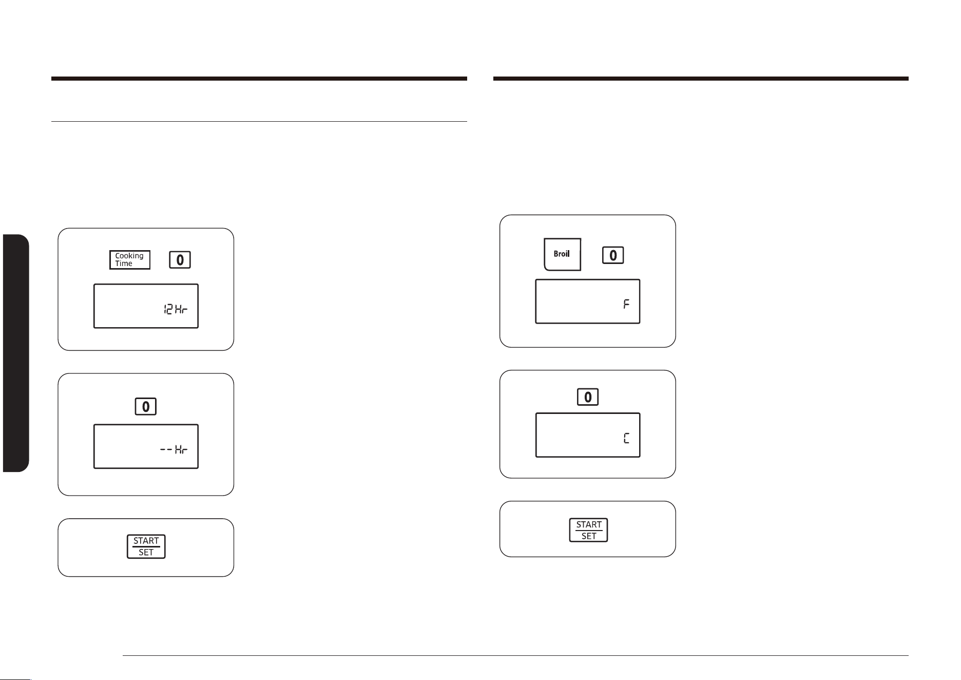
56 English
Operating the oven
Operating the oven
Fahrenheit or Centigrade Temperature Selection
The oven control can be programmed to display temperatures in Fahrenheit or
Centigrade.
The oven has been preset at the factory to display in Fahrenheit.
How to change the display from Fahrenheit to Centigrade or from Centigrade to
Fahrenheit.
1. Press the Broil and 0 pads at the same
time for 3 seconds.
The display will show F (Fahrenheit) or C
(Centigrade).
The default is F.
2. Press the 0 pad to select F or C. Pressing
the 0 pad toggles between F and C.
3. Press the START/SET pad to save and
set the temperature selection.
Extra features
12-Hour/3-Hour Energy-Saving
With this feature, should you forget and leave the oven on, the control will
automatically turn off the oven after 12 hours during baking functions or after 3
hours during a broil function.
How to turn 12-hour energy-saving feature on or off.
1. Press the Cooking Time and 0 pads at
the same time for 3 seconds.
The display will show 12 Hr (12 hours
shut-off) or -- Hr (no shut-off).
The default is 12 Hr.
2. Press the 0 pad to select ON (12 Hr) or
OFF (-- Hr).
3. Press the START/SET pad to save and
start the feature settings.
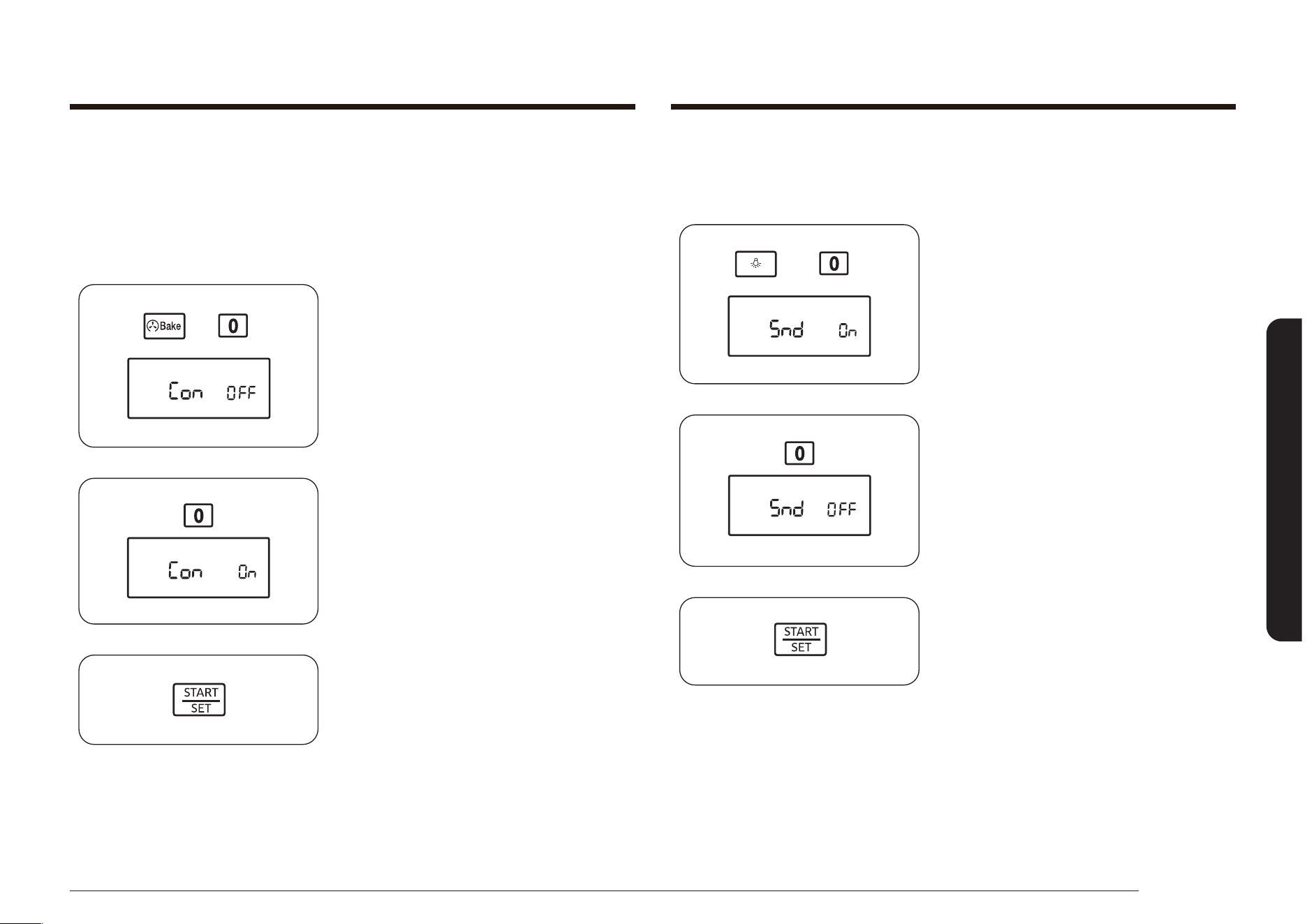
English 57
Operating the oven
Sound On/Off
By using this feature, you can set the oven controls to operate silently.
How to turn the sound on or off.
1. Press the Oven Light and 0 pads at the
same time for 3 seconds.
The display will show Snd On (sound on)
or Snd OFF (sound off).
The default setting is Snd On.
2. Press the 0 pad to toggle between Snd
On and Snd OFF.
3. Press the START/SET pad to save and
set the audible signal setting.
Convection Auto Conversion Feature
When using convection bake, the convection auto conversion feature will
automatically convert entered regular baking temperatures to convection baking
temperatures. This feature is activated so that the display will show the actual
converted (reduced) temperature.
How to enable or disable the auto conversion feature.
1. Press the Convection Bake and 0 pads
at the same time for 3 seconds.
The display will show Con On (enabled)
or Con OFF (disabled).
The default setting is Con OFF.
2. Press the 0 pad to select Con On or Con
OFF.
3. Press the START/SET pad to save and
set the auto conversion feature.
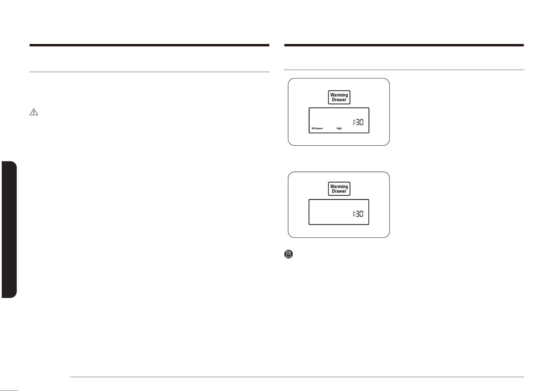
58 English
Using the warming drawer
Using the warming drawerUsing the warming drawer
About the warming drawer (Model NX58*565*** Only)
The Warming Drawer lets you keep hot, cooked foods warm. Always start with hot
food. Do not use the warming drawer to heat or reheat cold food.
Allow approximately 25 minutes for the warming drawer to preheat.
CAUTION
Do not use plastic containers or plastic wrap in the warming drawer. The
plastic will melt upon direct contact with the drawer. Melted plastic may not be
removable and is not covered under the warranty.
• Do not line the warming drawer with aluminum foil. Foil is an excellent heat
insulator and will trap heat beneath it. This will upset the performance of the
drawer and could damage the interior nish.
• Do not put liquid or water in the warming drawer.
• All foods placed in the warming drawer should be covered with a lid or
aluminum foil. When warming pastries or breads, vent the cover to allow
moisture to escape.
• Remove serving spoons, etc., before placing containers in the warming drawer.
• Food should be kept hot in its cooking container or transferred to a heat-safe
serving dish.
• The warming drawer cannot be used during a self-cleaning cycle.
• The warming drawer will shut off automatically after 3 hours.
Turning the warming drawer on or off
1. Press the Warming Drawer pad once
for low warming temperature, twice for
medium warming temperature, three
times for high warming temperature,
or four times to shut off the warming
drawer.
Warming Drawer and the selected
temperature light will show on the
display, and the warming drawer will
start to heat.
2. To shut off the warming drawer, press
the Warming Drawer pad until the
drawer shuts off.
NOTE
Pressing the OFF/CLEAR pad does not turn off the warming drawer.
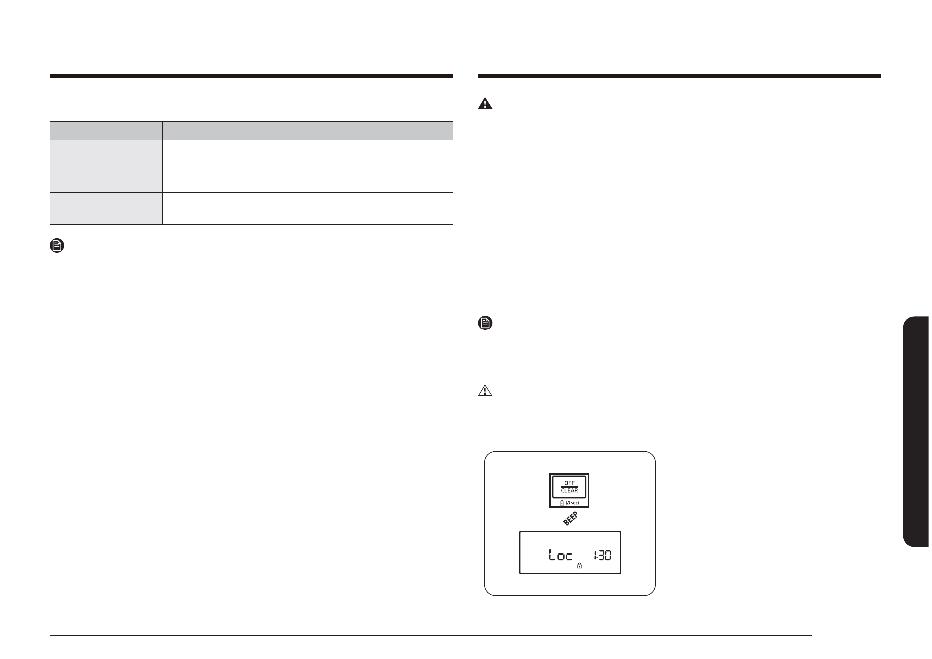
English 59
Maintaining your appliance
Recommended settings
DRAWER SETTING TYPE OF FOOD*
LOW Soft rolls, empty dinner plates
MED
Roasts (beef, pork, lamb), casseroles, vegetables, eggs,
pastries, biscuits, hard rolls, gravies
HIGH
Poultry, pork chops, hamburgers, pizza, bacon, fried
foods
NOTE
* Different types of food may be placed in the warming drawer at the same time.
For best results, do not leave food in the warming drawer for longer than 1 hour.
Do not leave smaller quantities or heat-sensitive foods, such as eggs, for longer
than 30 minutes.
Maintaining your appliance
WARNING
• Always make sure the controls are OFF and all surfaces are cool before
removing and/or cleaning any of the range parts. This will prevent you from
getting burned.
• If the range is pulled out from the wall for any reason, make sure the anti-tip
device is reengaged after the range has been pushed back into place. Failure
to take this precaution could result in the range tipping and personal injury.
• Take care not to hurt yourself when cleaning the appliance (externally or
internally). You may hurt yourself on the sharp edges of the appliance.
Care and cleaning of the oven
The oven and surface burner control panels can be easily cleaned with a damp
cloth and/or glass cleaner. Heavily soiled areas can be cleaned with warm, soapy
water.
NOTE
Never use steel wool or abrasive cleansers.
Protect the surface from sharp objects.
All of the above items can damage the surface.
CAUTION
Wear the glove during cleaning.
Oven control panel
1. To lock the oven controls and the oven
door, press and hold the OFF/CLEAR pad
for 3 seconds. This prevents accidental
oven operation and appliance tipping.
The oven will beep and the display will
show Loc, the time of day, and the Lock
icon.
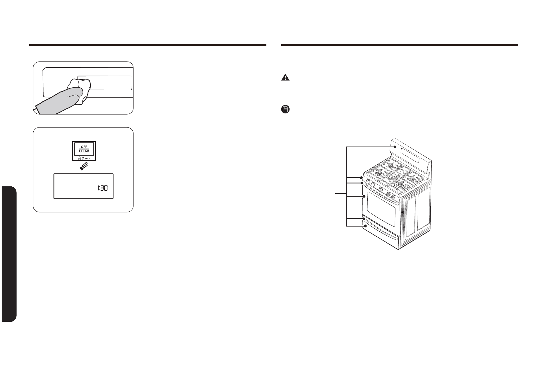
60 English
Maintaining your appliance
Maintaining your appliance
2. Clean spatters with a damp cloth, glass
cleaner, or warm, soapy water.
3. To unlock the controls and the door,
press and hold the OFF/CLEAR pad for
3 seconds.
To unlock just the controls, hold the
door slightly open while pressing
and holding the OFF/CLEAR pad for 3
seconds.
The oven will beep, and Loc and the
Lock icon will disappear from the
display. Close the oven door, if you are
holding it open.
Stainless steel surfaces
WARNING
Do not use a steel-wool pad or abrasive cleaners on stainless steel surfaces.
Abrasive pads and cleaners will scratch the surface and damage the surface nish.
NOTE
To prevent any discolorations and/or grease stains, we recommend cleaning and
removing any spills, spots, and grease from the range after each use.
Stainless steel
surfaces
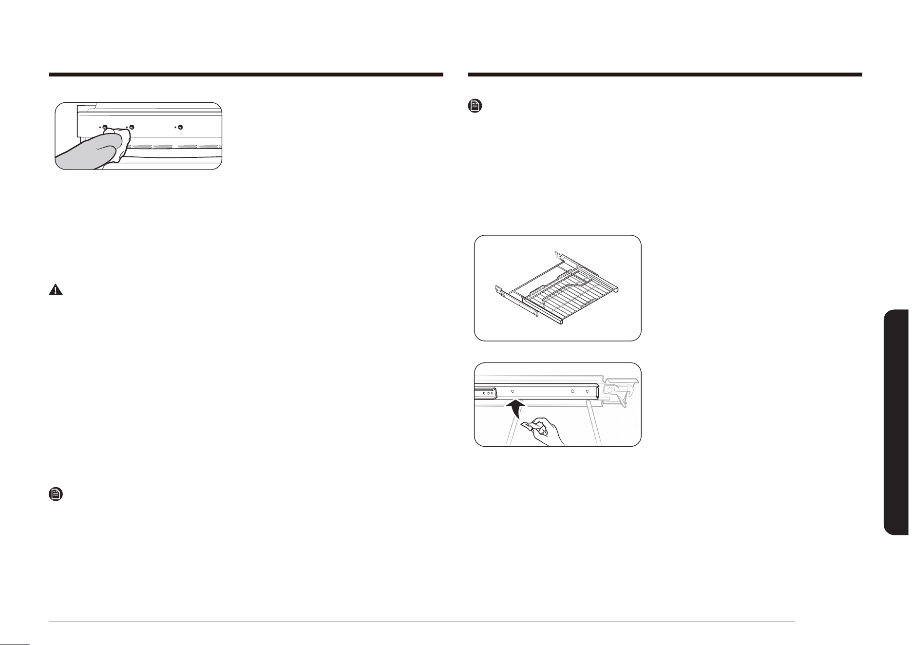
English 61
Maintaining your appliance
1. Wipe off any spills with a damp, soft
cloth.
2. Apply an approved stainless steel
cleaner to a damp, clean cloth or paper
towel. Clean a small area carefully
following the instructions on the
cleaner. Stainless steel should always be
cleaned with the grain in the stainless
steel, if applicable.
3. Dry and buff with a clean, dry, soft
cloth.
4. Repeat steps 2 and 3 as necessary.
WARNING
Do not spray any type of cleaner into the manifold panel holes. Within these
holes are ignition switches which carry the current that lights the surface burners.
Spraying into them could damage the range.
Oven racks
• If the racks are left in the oven during a self-cleaning cycle, their color will
turn slightly blue and the nish will be dull. After the self-cleaning cycle is
complete and the oven has cooled, rub the sides of the racks with wax paper
or a cloth containing a small amount of oil. This will help the racks glide more
easily into their tracks.
• Gliding racks may be cleaned by hand with an abrasive cleaner or steel wool.
During cleaning, be careful not to allow water or cleaner to enter the slides on
the sides of rack.
NOTE
• Do not clean in a dishwasher.
• If the rack becomes hard to remove or replace, lightly wipe the oven rack
guides with cooking oil. Do not wipe cooking oil on the slides.
• If the rack becomes difcult to slide, the rack may need to be lubricated using
Graphite Lubrication.
NOTE
• To order Graphite Lubrication, call our customer center at
1-800-SAMSUNG (726-7864) or visit our homepage
(www.samsung.com/us/support, www.samsung.com/ca/support (English) or,
www.samsung.com/ca_fr/support (French)) and reference DG81-01629A.
• If you want to buy directly, visit our on-line parts distributor at
http://www.samsungparts.com/Default.aspx.
To lubricate the slides
1. Remove the rack from the oven. See
removing the gliding rack in the Using
the gliding rack section.
2. Fully extend the rack on a table or
countertop. Newspaper may be placed
underneath the rack for easy cleanup.
3. If there is debris in the slide tracks,
wipe it away using a paper towel.(Any
graphite lubricant wiped away must be
replaced - See steps 4 through 7.
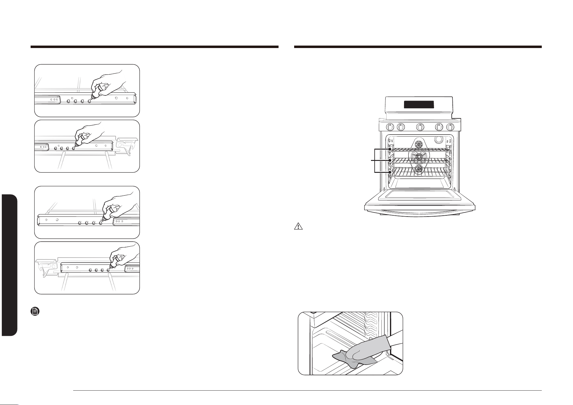
62 English
Maintaining your appliance
Maintaining your appliance
4. Shake the graphite lubricant before
opening it. Starting with the left (front
and back) slide mechanism of the rack,
place four (4) small drops of lubricant
on the two (2) bottom tracks of the slide
close to the bearing carriers.
5. Repeat for the right (front and back)
slide mechanism of the rack.
6. Open and close the rack several times to
distribute the lubricant.
7. Replace the cap on the lubricant and
shake it again. Turn the rack over and
repeat steps 3, 4, 5 and 6.
8. Close the rack, turn rack right-side-up
and place in the oven. See installing the
gliding rack in the Using the gliding rack
section.
NOTE
Do not spray the gliding rack with cooking spray or other lubricant sprays.
Oven racks
To keep racks shiny and looking like new, remove racks from the oven and clean
by hand in hot, soapy water with a plastic or soap-lled scouring pad.
Oven
Racks
CAUTION
Do not leave the oven racks in the oven during a self-cleaning cycle. The extreme
heat in the self-cleaning cycle will permanently discolor the oven racks and make
them difcult to slide.
If racks become difcult to slide, rub the side rails with wax paper or a cloth
containing a small amount of cooking oil. This will help the racks slide more easily
in the tracks.
Oven
Wear the glove during cleaning.
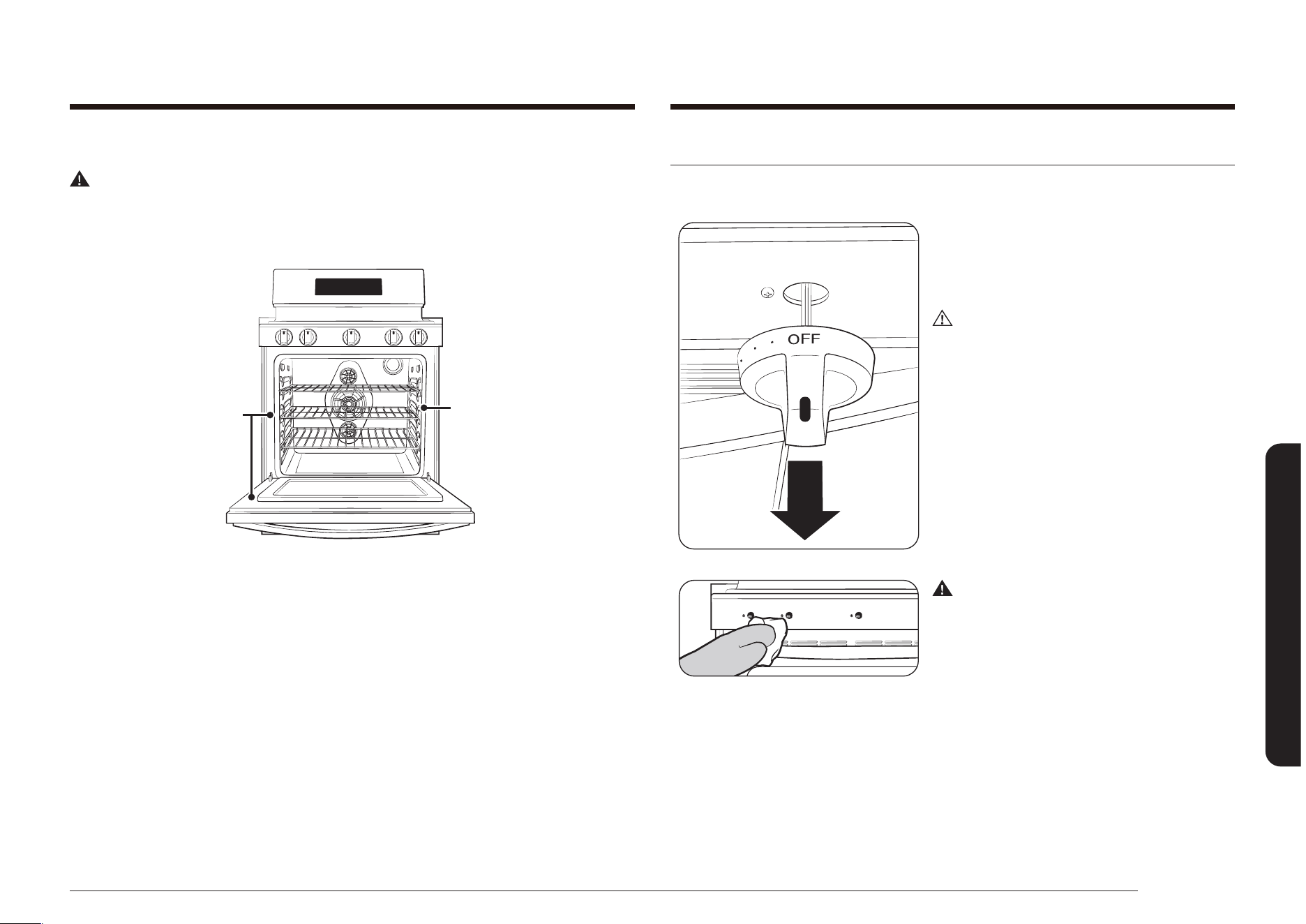
English 63
Maintaining your appliance
Care and cleaning of the cooktop
Surface burner controls
1. Make sure all surface burner knobs are
in the OFF position.
2. Pull the control knobs straight off the
surface burner control valve stems.
CAUTION
Do not clean the control knobs in a
dishwasher. They are not dishwasher-safe.
3. Clean the control knobs in warm, soapy
water. Rinse and completely dry all
surfaces (including back and stem hole).
WARNING
Do not use spray cleaners on the surface
burner control panel. Spray entering
the valve holes could contact electrical
components resulting in death, personal
injury, or product damage.
4. Clean stainless steel surfaces with
stainless steel cleaner on a damp, soft
cloth. See page 60.
Oven door
WARNING
Do not allow moisture to enter the door or contact the door gasket during
cleaning. Moisture entering the door assembly and or getting on the door gasket
will damage the gasket.
Do not move or
clean gasket.
Handclean gray
areas.
The oven door has multiple surfaces that require different cleaning techniques.
The gasket on the inside surface of the oven door should never be cleaned or
moved to clean other surfaces. The gasket is made of woven material which is
essential for a good heat seal.
The inside door surface outside of the gasket should be cleaned by hand with
hot, soapy water and a soapy plastic scouring pad. Rinse and dry thoroughly with
a clean, soft cloth. Do not get the gasket wet or allow moisture to get inside the
door assembly.
The inside door surface inside of the gasket and the inside door glass are cleaned
during the oven’s self-cleaning cycle.
The outside door surface is stainless steel and should be cleaned using the
instructions on page 60.
The outside glass surface can be cleaned with glass cleaner or warm, soapy water
with a thorough rinse. Do not let moisture get inside of the door assembly.
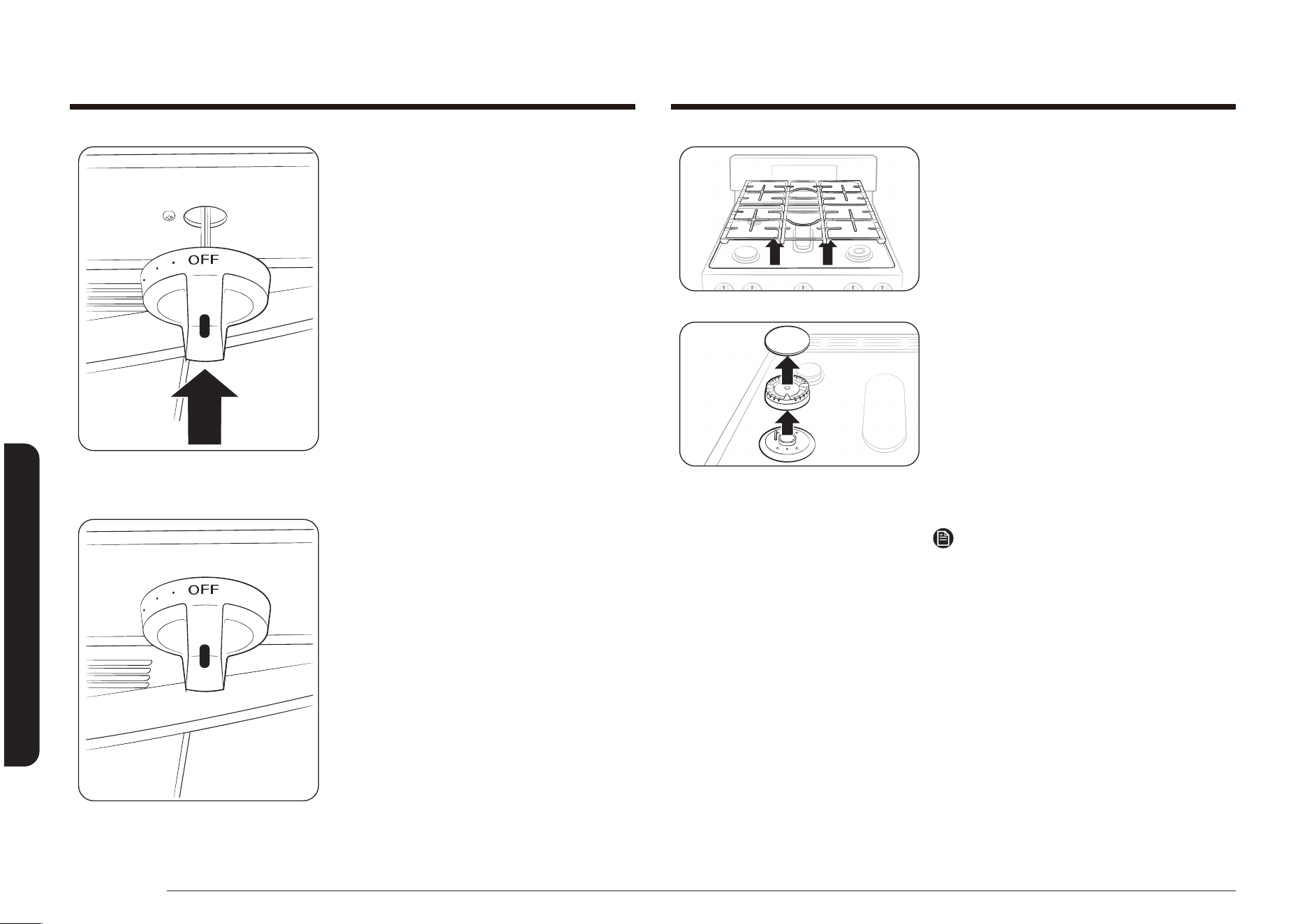
64 English
Maintaining your appliance
Maintaining your appliance
2. Lift off and remove the burner grates
from the cooktop. Make note of the
burner sizes and locations of all the
surface burners.
3. Lift off burner caps from top of the
burner heads.
4. Lift the burner heads off the valve
manifolds and starter electrodes.
5. Clean all removable burner parts in
warm, soapy water. Do not use steel-
wool pads or abrasive cleaners on any
burner part.
6. Rinse thoroughly and completely dry all
parts before they are reassembled.
NOTE
• After cleaning, conrm that the burner
port openings aren't plugged.
• Shake out any excess water and then let
burner heads and caps dry thoroughly.
Placing the center burner upside down
will allow the water to drain out more
easily.
• Do not wash any burner components in
a dish washer.
5. Replace the control knobs in the OFF
position by pushing them straight onto
the control valve stems.
Surface burner grates and assemblies
1. Turn off all controls and make sure all
parts have cooled.
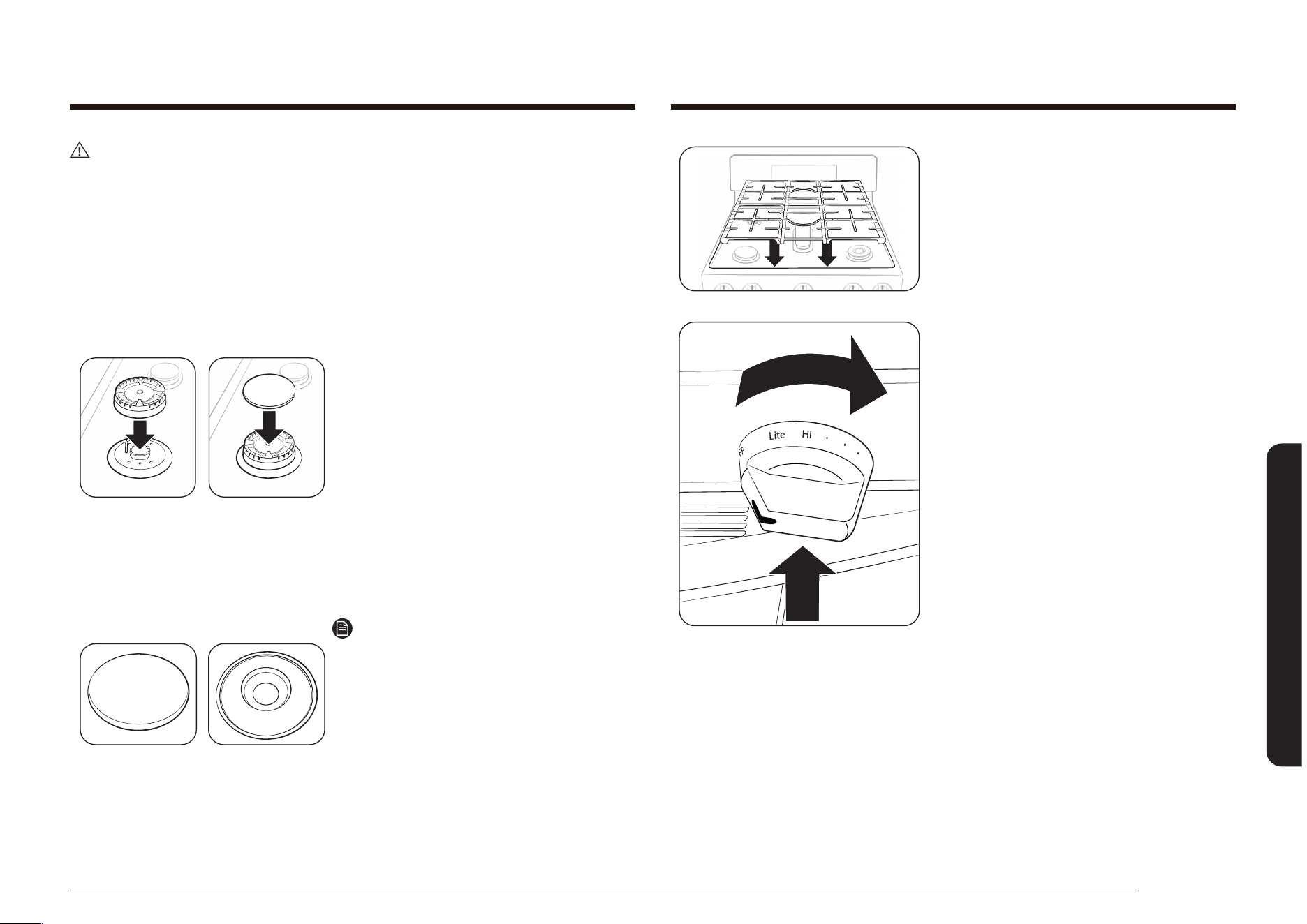
English 65
Maintaining your appliance
9. Replace burner grates on top of the
range cooktop.
10. Push in and turn each surface burner
control knob to the LITE position, let
each burner light, and then set each
control knob back to a burner setting
to make sure each burner operates
properly.
CAUTION
• The starter electrodes are not removable. Do not attempt to remove them by
force.
• To avoid chipping, do not bang grates and caps against each other or against
hard surfaces, such as cast iron cookware.
• The burner head can be blocked by food or dust. Clean the head if it appears
blocked. If you clean the head with water, assemble it only after it is
completely dry. If the head is wet, it might prevent the burners from igniting.
• To avoid falling down the grates, make sure to remove both sides grates rst.
• Do not attempt to remove center oval burner cap from the head.
7. Set all burner heads on top of the
manifold valves in the same location
you removed them from. The hole on
the side of the burner heads goes over
the electrodes. The burner heads are
correctly installed when they are at on
the top of the manifold valves.
8. Set all burner caps on top of the burner
heads.
These also need to be at on top of the
burner heads to ensure proper and safe
operation.
Precise Simmer Burner (RR)
NOTE
The caps on Precise simmer burner (RR)
and inside Double-ring Burner (RF) can be
interchangeably used.
Flat surface Concave line
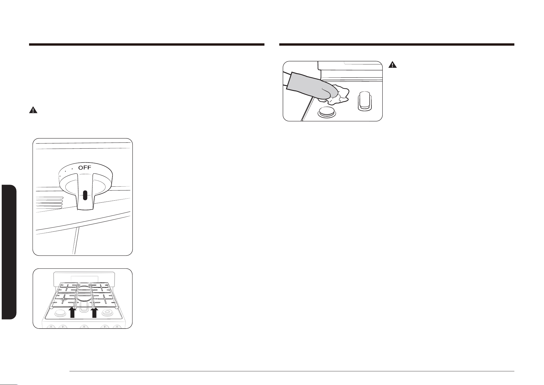
66 English
Maintaining your appliance
Maintaining your appliance
WARNING
Do not remove or lift the cooktop during
cleaning. Doing so could damage the
gas lines leading to the surface burner
manifolds, causing poor and/or dangerous
operation.
3. Clean the cooktop surface with warm,
soapy water and a soft, damp cloth.
If spill goes under a surface burner,
remove the surface burner cap and head
to access and clean the spill.
4. Rinse with clean water and dry and
polish with a soft, dry cloth.
5. Reassemble burner components (if
removed) and replace the burner grates.
Cooktop surface
The cooktop surface is a porcelain-enamel surface. To prevent this surface from
becoming dull, wipe up and clean spills as they happen. Foods with a lot of acid
(tomatoes, sauerkraut, fruit juices, etc.) or foods with high sugar content can cause
dull spots if allowed to set.
WARNING
Do not use a steel-wool pad or abrasive cleaners on porcelain-enamel surfaces.
Abrasive pads and cleaners will scratch and damage the surface.
1. Make sure all surface burners are OFF.
2. When surfaces have cooled, remove the
burner grates.
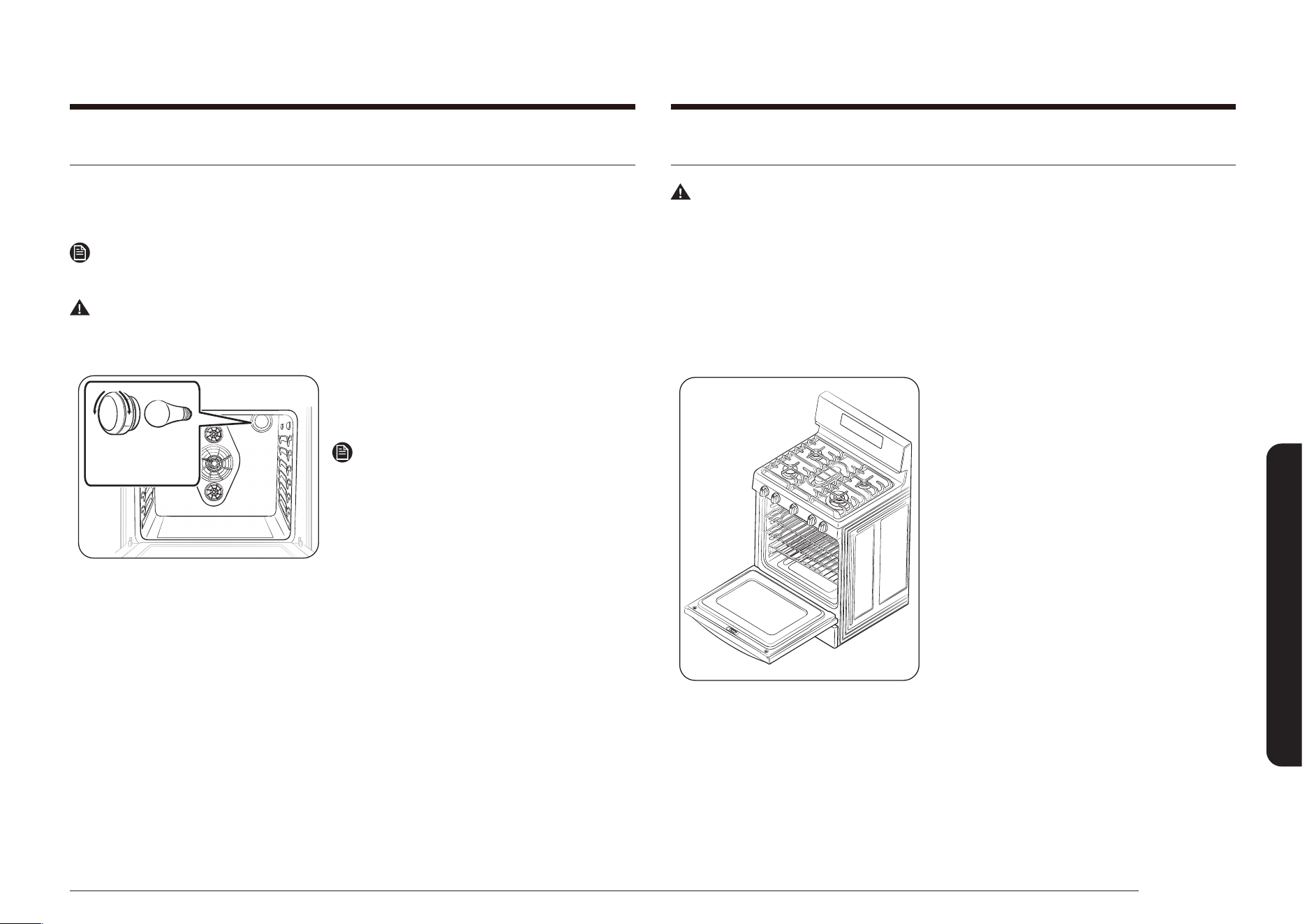
English 67
Maintaining your appliance
Removing and replacing the oven door
WARNING
• The oven door is very heavy. Do not lift it by the handle and be careful not
to drop the door during removal. Improper handling could result in personal
injury.
• Disconnect the electrical power to the range before removing the oven door.
This prevents the oven from accidentally being turned on while the door is
removed.
To remove the door
1. Completely open the oven door.
Changing the oven light
The oven light is a standard 40-watt appliance bulb. It will automatically come on
when the oven door is opened. It can also be turned on and off when the oven
door is closed by pressing the Oven Light pad on the oven control panel.
NOTE
The oven light will not work during a self-cleaning cycle.
WARNING
Disconnect electrical power to the range before replacing the oven light. This will
prevent any personal injury due to electric shock.
Oven light cover
and bulb
1. Make sure the oven and the light bulb
are cool.
2. Open the oven door.
NOTE
If the oven racks are in the way, they can
be repositioned or removed before you
change the oven light.
3. Turn the glass light cover in the rear
upper-right corner counterclockwise to
remove it.
4. Turn the bulb counterclockwise to
remove it from its socket.
5. Replace the bulb with a new 40-watt
appliance bulb. Turn the bulb clockwise
until it is seated securely in the socket.
6. Replace the glass light cover by turning
it clockwise until it is seated securely.
7. Close the oven door and reconnect the
electrical power to the range.

68 English
Maintaining your appliance
Maintaining your appliance
2. Firmly grasp both sides of the door.
3. While supporting the oven door, insert
both door hinge arms into the slots in
the bottom sides of the door frame.
When the door is held at about 5
degrees, the hinge arms will slide in and
down.
Hinge
lock
4. Completely open the oven door. If the
door will not fully open, the hinge arms
are not correctly inserted into the slots
in the bottom of the door.
5. Lock both hinge locks. Push each lock
up against the front frame of the oven
cavity.
6. Close the door.
7. Reconnect power to the range.
Hinge
lock
2. Unlock the two hinge locks. Pull each
hinge lock down towards the door
frame to unlock it so they look like the
illustration to the right.
3. Close the door to the removal position,
approximately 5 degrees from vertical.
4. Firmly grasp both sides of the oven
door and lift the door up and out until
the hinge arms clear the slots in the
bottom of the oven door.
5. Carefully place the door in a safe
location.
To replace the door
1. Make sure hinge arms are unlocked and
in the removal position.
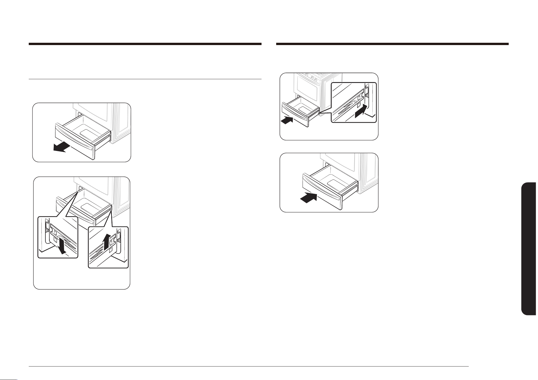
English 69
Maintaining your appliance
To replace the warming drawer
Right roller
guide rail
1. Position the ends of the full-extension
roller guide rails in the side rails in the
drawer opening.
2. Push in the drawer to close it and snap
the locking clips into place.
Removing and replacing the warming drawer
(Model NX58*565***)
To remove and clean the warming drawer
1. Pull out the drawer until it stops.
Right drawer
locking clip
Left drawer
locking clip
2. Locate the locking clips near the back
of each full-extension roller guide rail.
Using two hands, push down on the
left clip and lift up on the right clip to
release the clips. Pull the drawer the
rest of the way out.
3. Clean the drawer in warm, soapy water.
Rinse and dry thoroughly.

70 English
Maintaining your appliance
Maintaining your appliance
To replace the storage drawer
1. Place the top of both drawer sides in
the openings on the two nylon drawer
guides and push in enough to support
the drawer.
2. Replace any stored content and push
in the drawer while slightly lifting the
front to close it.
Removing and replacing the storage drawer
(Model NX58*560***, NX58*751***)
To remove the storage drawer
1. Pull out the drawer and remove any
stored content.
2. While supporting the drawer, pull it out
until the top of the drawer sides come
out of the two nylon drawer guides.
Then, lift to remove the drawer.
3. Clean the drawer in warm, soapy water.
Rinse and dry thoroughly.
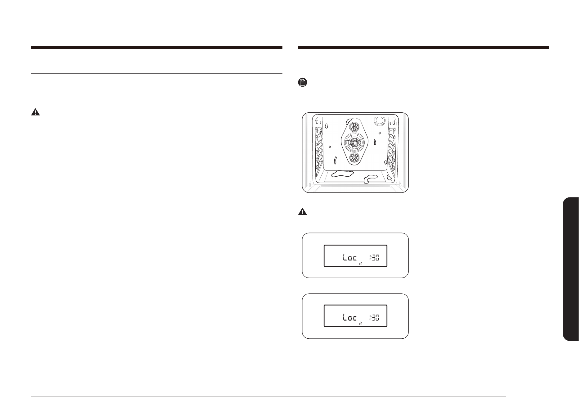
English 71
Maintaining your appliance
Before a self-cleaning cycle
NOTE
Remove the racks. Leaving the oven racks in the oven during a self-cleaning cycle
will discolor the oven racks and make them difcult to slide in and out of position.
• Make sure the door lock feature is
turned off and the oven is cool. If they
are not, the self-cleaning cycle will not
start.
• On model NX58*565***, make sure the
warming drawer is turned off. Self-clean
will not start when the drawer is on.
WARNING
Do NOT use the surface burners while the oven is operating in the self clean mode.
• A blinking Loc icon indicates the oven
door is in the process of being locked.
• When the Loc icon is on, the oven door
is locked.
Self-cleaning oven
The self-cleaning oven uses high temperatures (well above cooking temperatures)
to burn off left over grease and residue completely or reduce them to a nely
powdered ash that can be wiped away with a damp cloth.
WARNING
Failure to follow these precautions could result in damage to the oven, re, and/or
personal injury.
• Do not leave small children unattended near the range during a self-cleaning
cycle. The outside surfaces of the range can get extremely hot.
• Some birds are extremely sensitive to fumes from a self-cleaning oven.
Relocate birds to a well-ventilated room away from the range.
• Do not line the oven, oven racks, or oven bottom with aluminum foil. Doing
so will result in poor heat distribution, produce poor baking results, and cause
permanent damage to the oven interior. The aluminum foil will melt onto and
adhere to the interior oven surfaces.
• Do not force the oven door open during the self cleaning cycle. It will damage
the automatic door-locking system. The door automatically locks when the
self-cleaning cycle is started and stays locked until the cycle is cancelled and
the oven temperature is below 350 °F.
• Be careful opening the oven door after a self-cleaning cycle. The oven will still
be VERY HOT and hot air and steam might escape when the door is opened.
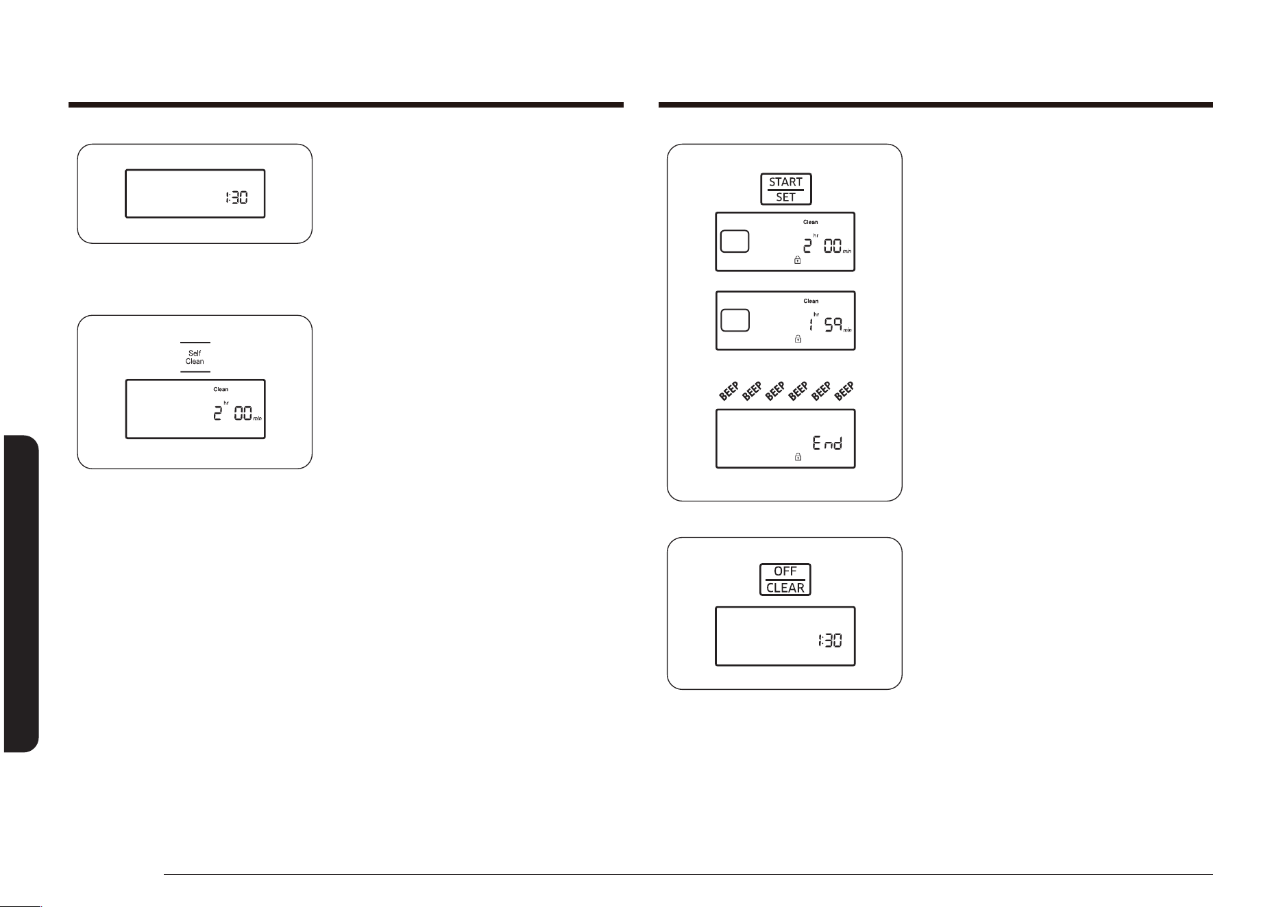
72 English
Maintaining your appliance
Maintaining your appliance
3. Press the START/SET pad to start the
cycle.
The display will show Clean and the
selected cleaning cycle time, and the
Lock icon will blink until the door is
locked. Then the Lock icon will stay
on until the cycle is over and the oven
temperature is below 350 °F (177 °C).
The oven temperature will rise and hold
the preset self-clean temperature for the
duration of the selected cleaning cycle.
The display will count down the cleaning
cycle in minutes and hours.
When the time elapses, the oven will
turn off and beep 6 times. End will show
in the display and the Lock icon will
blink. When the oven temperature falls
below 350 °F (177 °C), the door unlocks
and the Lock icon turns off.
4. Press the OFF/CLEAR pad.
The display will go back to showing the
time of day.
• When Loc is shown in the display, it
indicates the door lock feature is on.
Press and hold the OFF/CLEAR pad for 3
seconds to unlock the oven controls.
How to set the oven for self-cleaning
1. Make sure the oven door is completely
closed.
2. Press the Self Clean pad on the oven
control panel.
Press the pad once for a 2-hour cleaning
cycle, twice for a 3-hour cleaning cycle,
or three times for a 4-hour cleaning
cycle.
Pressing the pad a fourth time will
reselect the 2-hour default time.
The display will show Clean, and the
Start indicator will blink under the
selected cleaning cycle time.
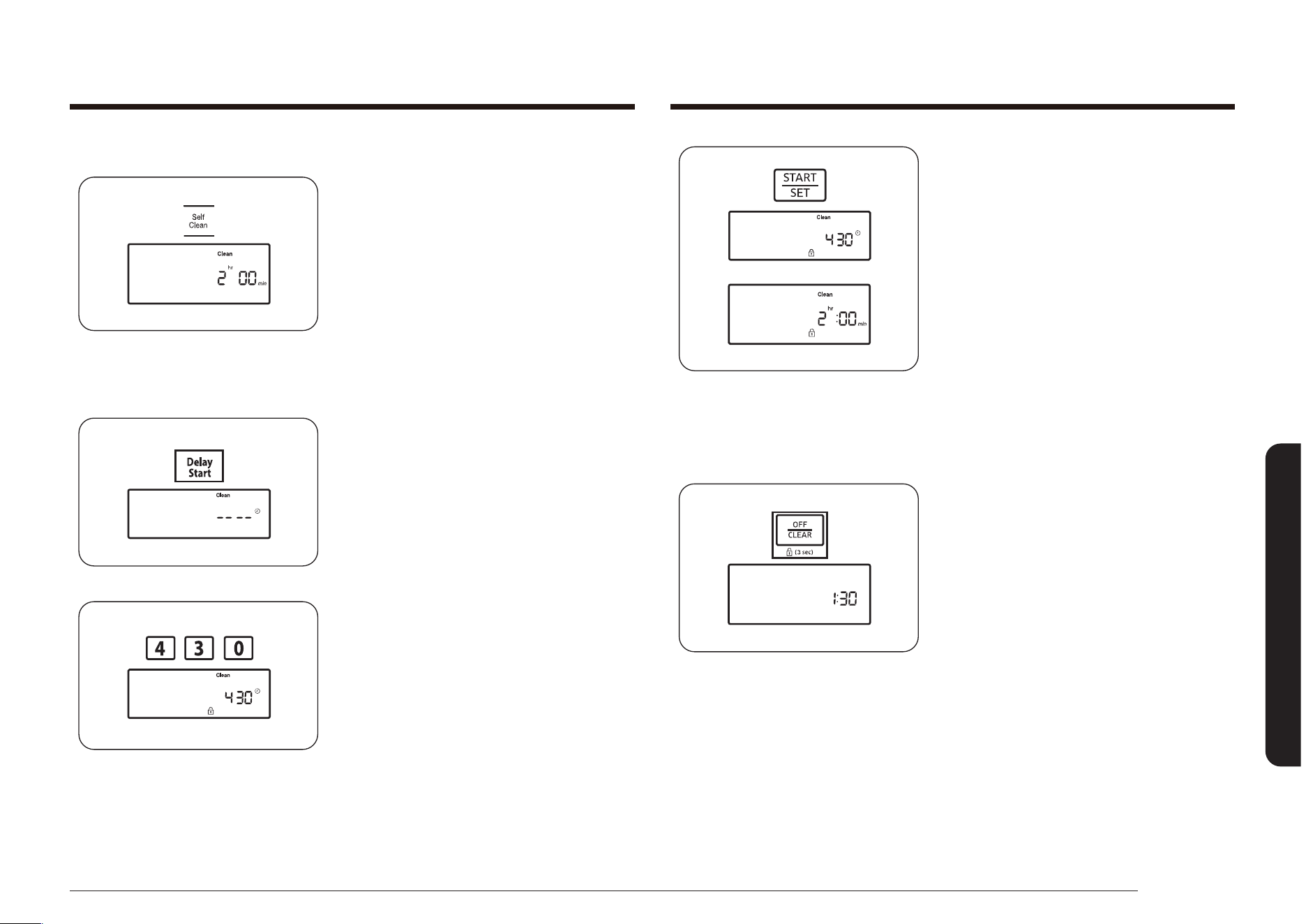
English 73
Maintaining your appliance
5. Press the START/SET pad.
The display will show the Delay Start
time and the Lock icon. The oven door
lock will engage automatically.
When the start time is reached, the oven
will turn on automatically and start the
programmed cleaning cycle.
How to cancel self-cleaning
You may nd it necessary to stop or interrupt the self-cleaning cycle due to
excessive smoke or re in the oven.
• Press the OFF/CLEAR pad.
The oven will turn off. The Lock icon will blink under the current time of day on
the display. When the oven temperature falls below 350 °F (177 °C), the oven door
unlocks and the Lock icon turns off.
How to delay the start of self-cleaning
1. Make sure the oven door is completely
closed.
2. Press the Self Clean pad on the oven
control panel.
Press the pad once for a 2-hour cleaning
cycle, twice for a 3-hour cleaning cycle,
or three times for a 4-hour cleaning
cycle.
The display will show Clean, and the
Start indicator will blink under the
selected cleaning cycle time.
3. Press the Delay Start pad.
The display will show Delay and -- --.
4. Press the number pads to set the time
you want the oven to turn on,
e.g., 4, 3, 0.
The Start indicator will blink under the
selected delay start time and Delay on
the display.
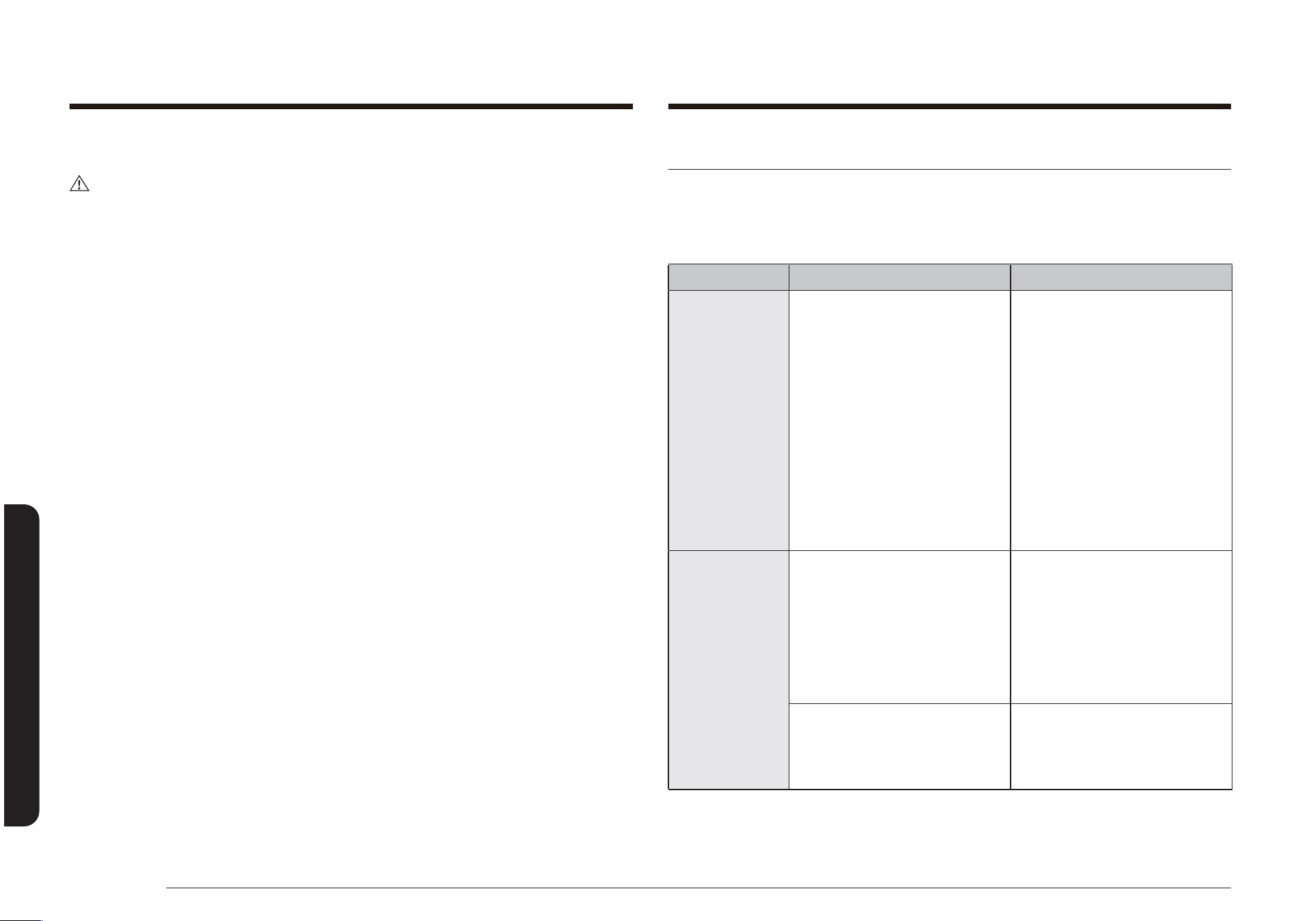
74 English
Troubleshooting
Troubleshooting
After self-cleaning
CAUTION
Be careful opening the oven door after a self-cleaning cycle. The oven is still very
hot when the door unlocks. Escaping hot air and/or steam could burn you.
• The internal oven temperature must be below 350 °F for the automatic door
lock to disengage. The door lock must be disengaged before another cooking
function can be set.
• After the oven has cooled, wipe down the oven surfaces with a damp cloth to
remove any ash residue.
• Stubborn spots can be cleaned with a soap-lled steel-wool pad. Lime deposits
can be removed with a cloth soaked in vinegar. Rinse thoroughly after
cleaning.
• If the oven is not clean after one cycle, repeat the cycle. If the oven is still hot,
HOT will appear on the display until the oven is cool enough to start a new
cycle.
• Self-cleaning does not operate within 2 hours after running the self-cleaning
cycle.
Troubleshooting
Troubleshooting
Samsung works hard to ensure that you don’t have problems with your new gas
range. If you experience a problem, look rst for a solution in the table below. If,
after trying the suggested solution, you’re still having trouble, call Samsung at
1-800-SAMSUNG (726-7864).
PROBLEM POSSIBLE CAUSE SOLUTION
You smell gas. There is a gas leak.
The surface burner knob is
not in the ‘off’ position, yet
the burner itself is not ignited.
Clear the room, building, or
area of all occupants.
Immediately call your gas
supplier from a neighbor’s
phone. Do not call from your
phone. It is electrical and
could cause a spark that could
ignite the gas. Follow the gas
supplier’s instructions.
If you cannot reach your
gas supplier, call the re
department.
The range is
not level.
The appliance has been
installed improperly.
The leveling leg(s) is (are)
damaged or uneven.
Make sure the oor is level,
strong, and stable. If the
oor sags or slopes, contact a
carpenter.
Check and level the range.
(See the Installation
Instructions.)
The kitchen cabinets are not
properly aligned and make
the range appear to be not
level.
Ensure that cabinets are
square and provide sufcient
room for installation.

English 75
Troubleshooting
PROBLEM POSSIBLE CAUSE SOLUTION
The oven
control beeps
and displays
an error code.
You have a function error
code. See the Troubleshooting
and information codes chart
on page 80.
Press the OFF/CLEAR pad
and restart the oven. If the
problem persists, disconnect
all power to the range for at
least 30 seconds and then
reconnect the power. If this
does not solve the problem,
call for service.
All burners do
not light.
The power cord is not
plugged into the electrical
outlet.
Make sure the electrical
plug is plugged into a live,
properly grounded outlet.
A fuse in your home may be
blown or the circuit breaker
tripped.
Replace the fuse or reset the
circuit breaker.
The gas supply is not properly
connected or turned on.
See the Installation
Instructions that came with
your range.
Surface
burners do not
light.
The control knob is not set
properly.
Push in the control knob and
turn it to the LITE position.
The burner caps are not in
place.
The burner base is misaligned.
Clean the electrodes.
Put the burner cap on the
burner head. Align the burner
base.
PROBLEM POSSIBLE CAUSE SOLUTION
Surface burner
clicks during
operation.
The control knob has been left
in the LITE position.
After the burner lights, turn
the control knob to a desired
setting.
If the burner still clicks,
contact a service technician.
The burners
do not burn
evenly.
Surface burner components
and caps are not assembled
correctly and level.
See page 64.
Surface burners are dirty. Clean surface burner
components. (See pages 64
and 65.)
Very large or
yellow surface
burner ames.
Wrong orice is assembled. Contact your installer. Check
the burner orice size and
contact your installer if you
have the wrong orice. Check
the LP gas conversion.
Surface
burners light
but oven
burners do not
light.
The oven door lock is turned
on.
The display will show the
Lock icon. Hold the oven door
open and press the START/
SET pad for 3 seconds. The
oven will beep and the Lock
icon will turn off.
Gas Pressure Regulator
shut off switch is in the ‘off
position.
Call a qualied service
technician.
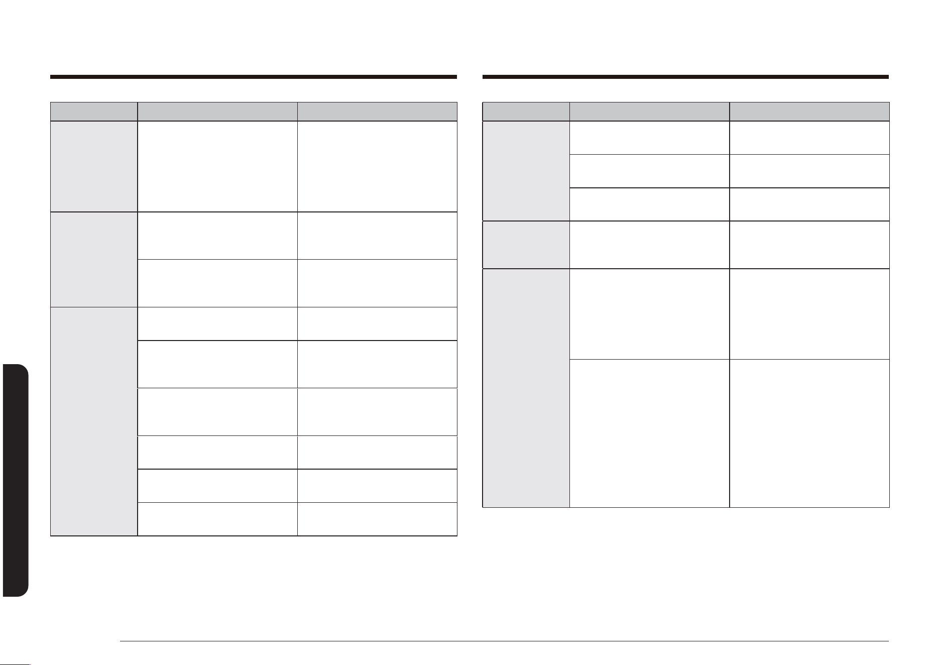
76 English
Troubleshooting
Troubleshooting
PROBLEM POSSIBLE CAUSE SOLUTION
Display goes
blank.
The electrical outlet Ground
Fault Interrupter (GFI or GFCI)
has been tripped and needs to
be reset.
Your digital control has been
damaged.
Replace fuse or reset circuit
breaker.
Very large or
yellow oven
burner ames.
The oven burner air
adjustment shutters need to
be adjusted.
Call for a qualied service
technician.
Gas supply is not properly
connected or turned on.
See the Installation
Instructions that came with
your range.
Food does not
bake or roast
properly in the
oven.
Wrong cooking mode is
selected.
See pages 30-31, 41,
47.
The oven racks have not been
positioned properly for the
foods being cooked.
See page 35.
Incorrect cookware or
cookware of improper size
being used.
See page 27.
Oven thermostat needs
adjustment.
See page 39.
There is aluminum foil on
racks and/or oven bottom.
Remove foil.
Clock or timers not set
correctly.
See pages 33 and 34.
PROBLEM POSSIBLE CAUSE SOLUTION
Food does not
broil properly
in the oven.
Oven controls not set
properly.
See page 46.
Oven door was not closed
during broiling.
See page 32.
The rack has not been
properly positioned.
See Broiling guide on page
47.
Oven
temperature is
too hot or cold.
Oven thermostat needs
adjustment.
See page 39.
Oven burner
will not shut
off.
The oven door lock is turned
on.
The display will show the
Lock icon. Hold the oven door
open and press the START/
SET pad for 3 seconds. The
oven will beep and the Lock
icon will turn off.
The Sabbath function has
been activated.
SAb and the time of day
will show in the display. All
other controls and signals
will be deactivated. To turn
off the oven only, press the
OFF/CLEAR pad. To cancel
the Sabbath function and
reactivate the controls and
signals, press and hold the
SABBATH pad for 3 seconds.
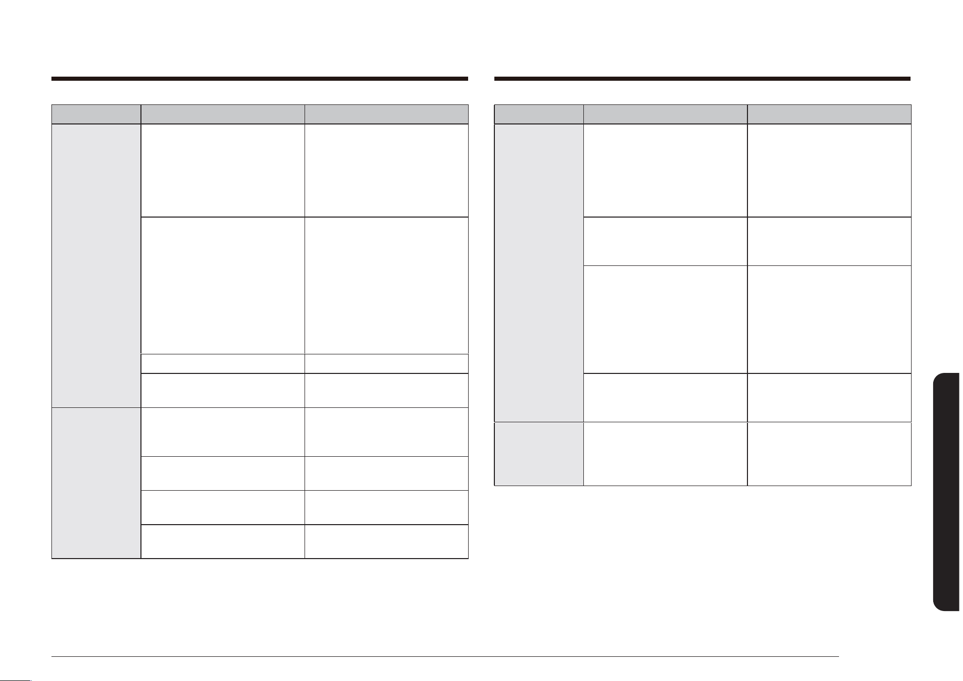
English 77
Troubleshooting
PROBLEM POSSIBLE CAUSE SOLUTION
Oven will not
self-clean.
The oven door lock is turned
on.
The display will show the
Lock icon. Hold the oven door
open and press the START/
SET pad for 3 seconds. The
oven will beep and the Lock
icon will turn off.
The warming drawer is being
used.
Self-clean will not operate
when the warming drawer
is on.
The oven is too hot. Let the oven cool down
and reset the controls. The
self-clean cycle will not lock
the oven door if the oven
temperature is too hot. The
door must lock before the
self-clean cycle can start.
The self-cleaning oven
controls are not properly set.
Reset the self-cleaning oven
controls. (See pages 72 and
73.)
Crackling or
popping sound.
This is normal. This is the sound of the metal
heating and cooling during
any cooking or cleaning
function.
PROBLEM POSSIBLE CAUSE SOLUTION
Oven light
(lamp) will not
turn on.
The oven door lock is turned
on.
The display will show the
Lock icon. Hold the oven door
open and press the START/
SET pad for 3 seconds. The
oven will beep and the Lock
icon will turn off.
The Sabbath function has
been activated.
SAb and the time of day
will show in the display. All
other controls and signals
will be deactivated. To cancel
the Sabbath function and
reactivate the light switch
and other controls, press and
hold the SABBATH pad for 3
seconds.
Loose or burned-out bulb. See page 67.
The switch operating the oven
light needs to be replaced.
Call for a qualied service
technician.
Oven smokes
excessively
during broiling.
Meat or food was not
properly prepared before
broiling.
Cut away excess fat and/or
fatty edges that may curl.
Improperly positioned top
oven rack.
See Broiling guide on page
47.
Controls are not being set
properly.
See page 46.
Greasy buildup on oven
surfaces.
Regular cleaning is necessary
when broiling frequently.
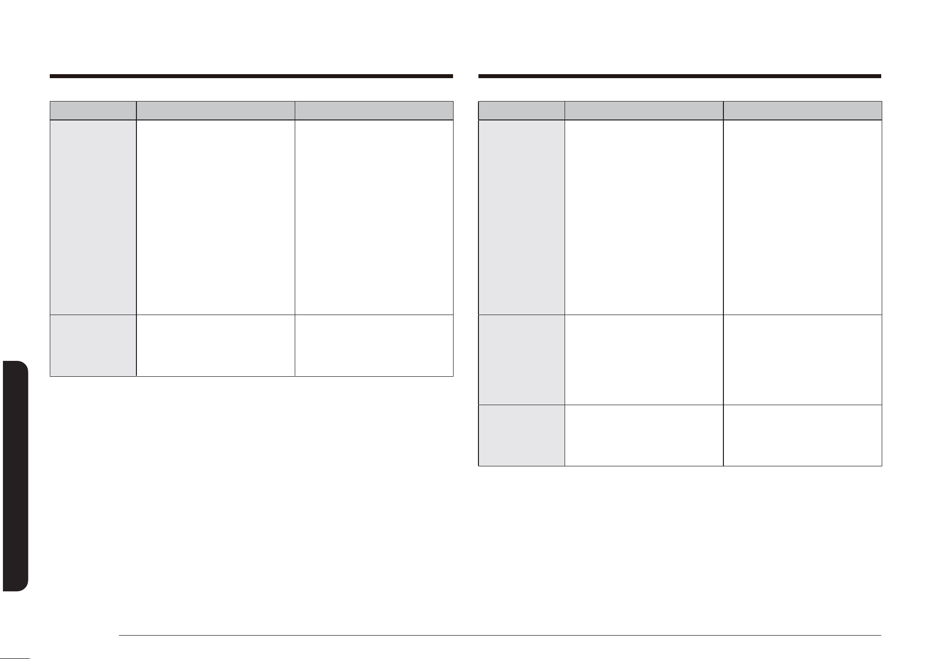
78 English
Troubleshooting
Troubleshooting
PROBLEM POSSIBLE CAUSE SOLUTION
Oven not clean
after a self-
cleaning cycle.
A ne dust or ash is normal. This can be wiped clean with
a damp cloth.
Set the self-cleaning cycle for
a longer cleaning time. The
cycle was not long enough to
burn off the dirt buildup.
Extremely dirty ovens require
hand-cleaning of excessive
spillovers and food buildup
before starting a self-cleaning
cycle. Multiple self-cleaning
cycles may be necessary to
completely clean the oven.
Steam or
smoke coming
from under the
control panel.
This is normal. The oven vent is located
there. More steam is visible
when using the convection
functions or when baking or
roasting multiple items at the
same time.
Burning or oily
odor emitting
from the vent.
This is normal for a new oven
and will disappear within 1/2
hour of the rst bake cycle.
To speed the process, set
a self-cleaning cycle for a
minimum of 3 hours. (See
pages 72 and 73.)
PROBLEM POSSIBLE CAUSE SOLUTION
Excessive
smoking
during a self-
cleaning cycle.
This is the rst time the oven
has been cleaned.
This is normal. The oven will
always smoke more the rst
time it is cleaned.
Wipe up all excessive soiling
before starting the self-
cleaning cycle.
If smoke persists, press the
OFF/CLEAR pad. Open the
windows to clear the smoke
from the room. After the oven
has cooled and unlocked, wipe
up excessive soil and reset
the oven for self-cleaning.
Oven door will
not open after
a self-cleaning
cycle.
This is normal. The oven door will stay
locked until the oven
temperature drops below
350 °F.
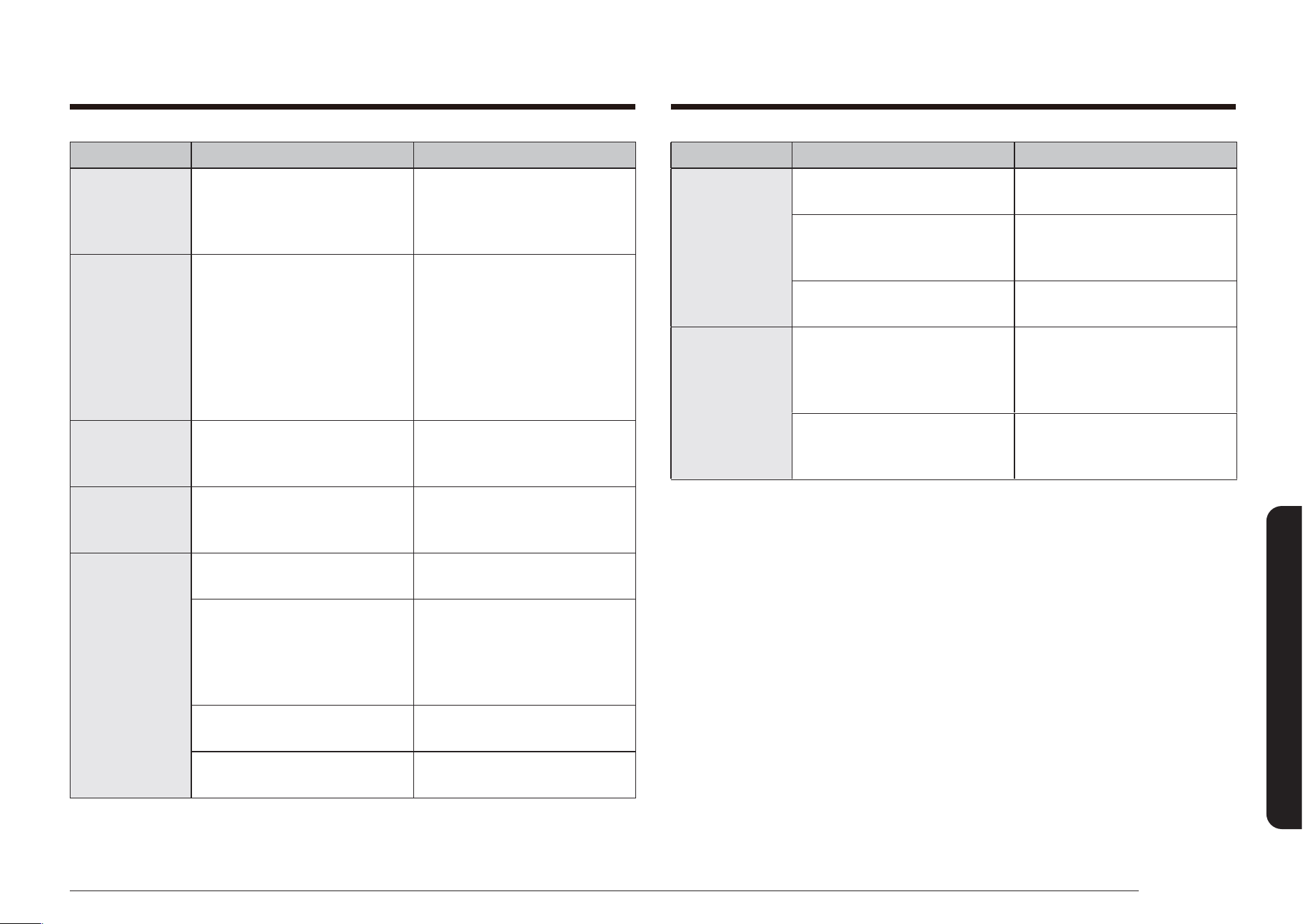
English 79
Troubleshooting
PROBLEM POSSIBLE CAUSE SOLUTION
Excessive
condensation
in the warming
drawer (Model
NX58*565**
*).
The temperature setting is too
high.
See page 58.
The foods being warmed
are not covered with a lid or
aluminum foil.
Cover foods with a lid or
aluminum foil.
You are trying to warm
liquids.
Liquid should not be warmed
in the drawer. Remove liquids.
Warming
drawer or
storage drawer
does not slide
smoothly or
drags.
The drawer is not properly
aligned with the full-
extension roller guide rails or
nylon drawer guides.
Remove and replace the
drawer. (See pages 69 and 70)
The contents in the drawer
are too heavy.
Reduce the weight and/or
redistribute the contents in
the drawer.
PROBLEM POSSIBLE CAUSE SOLUTION
Strong odor. This is temporary. The insulation around the
inside of the oven emits an
odor the rst few times the
oven is used.
Oven racks
are difcult to
slide.
Apply a small amount of
vegetable oil to a paper towel
and wipe edges of the oven
racks with the paper towel.
Racks become dull and hard
to slide when they are left in
the oven during a self-clean
cycle.
Fan noise. This is normal. The convection fan runs until
the function is over or the
door is opened.
Convection fan
is not working.
The fan starts automatically
when the oven meets the
preheat temperature.
Warming
drawer will not
work (Model
NX58*565**
*).
The controls are not set
properly.
Reset the controls as
described on pages 58.
The Self-Clean or Sabbath
function is being used.
The warming drawer will not
operate during either of these
operations. Try again after
the function is completed or
cancelled.
The oven controls have been
locked.
Unlock the controls and try
again.
There is a blown fuse or
tripped circuit breaker.
Replace blown fuse or reset
tripped circuit breaker.
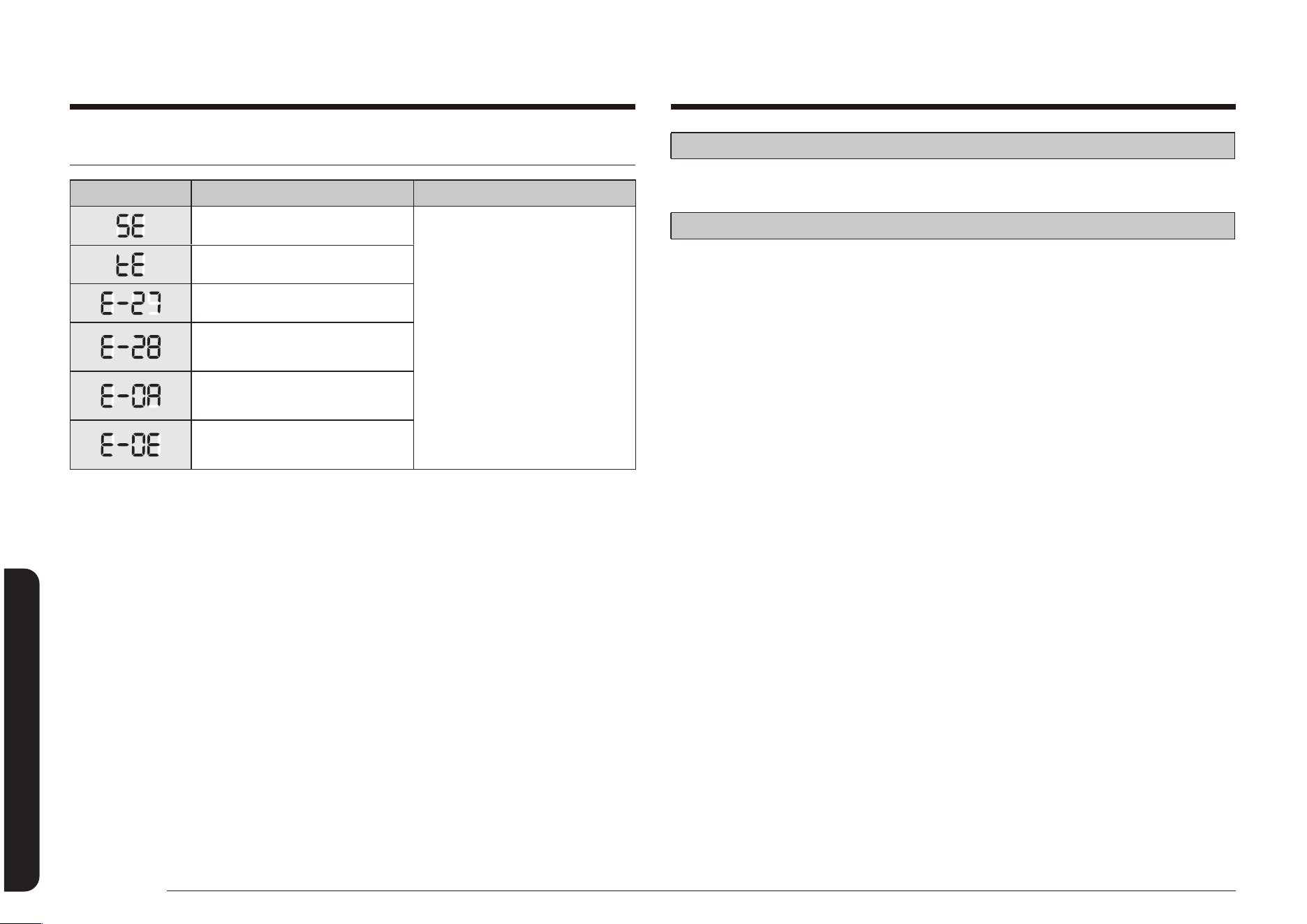
80 English
Warranty
Warranty
Troubleshooting and information codes
CODE SYMBOL MEANING SOLUTION
Shorted Key. Press the OFF/CLEAR pad and
restart the oven.
If the problem persists,
disconnect all power to the
range for at least 30 seconds
and then reconnect the
power.
If this does not solve the
problem, call for service. See
the instructions below this
chart.
Check the Touch PBA signals.
Oven sensor opened problem.
Oven sensor shorted problem.
Oven overheating.
Door locking error.
For any codes not listed above, or if the suggested solution does not x the
problem, call 1-800-SAMSUNG (726-7864).
Warranty (U.S.A)
PLEASE DO NOT DISCARD.
SAMSUNG GAS RANGE
LIMITED WARRANTY TO ORIGINAL PURCHASER WITH PROOF OF PURCHASE
This SAMSUNG brand product, as supplied and distributed by SAMSUNG
ELECTRONICS AMERICA INC. (SAMSUNG) and delivered new, in the original
carton to the original consumer purchaser, is warranted by SAMSUNG against
manufacturing defects in materials or workmanship for the limited warranty
period, starting from the date of original purchase, of:
One (1) Year Parts and Labor
This limited warranty is valid only on products purchased and used in the
United States that have been installed, operated, and maintained according to
the instructions attached to or furnished with the product. To receive warranty
service, the purchaser must contact SAMSUNG at the address or phone number
provided below for problem determination and service procedures. Warranty
service can only be performed by a SAMSUNG authorized service center. The
original dated bill of sale must be presented upon request as proof of purchase to
SAMSUNG or SAMSUNG’s authorized service center to receive warranty service.
SAMSUNG will provide in-home service within the contiguous United States
during the warranty period at no charge, subject to availability of SAMSUNG
authorized servicers within the customer’s geographic area. If in-home service is
not available, SAMSUNG may elect, at its option, to provide transportation of the
product to and from an authorized service center. If the product is located in an
area where service by a SAMSUNG authorized servicer is not available, you may
be responsible for a trip charge or required to bring the product to a SAMSUNG
authorized service center for service.
To receive in-home service, product must be unobstructed and accessible to the
service agent.

English 81
Warranty
During the applicable warranty period, a product will be repaired, replaced, or
the purchase price refunded, at the sole option of SAMSUNG. SAMSUNG may use
new or reconditioned parts in repairing a product, or replace the product with
a new or reconditioned product. Replacement parts and products are warranted
for the remaining portion of the original product’s warranty or ninety (90) days,
whichever is longer. All replaced parts and products are the property of SAMSUNG
and you must return them to SAMSUNG.
This limited warranty covers manufacturing defects in materials or workmanship
encountered in normal household, noncommercial use of this product and shall not
cover the following: damage that occurs in shipment, delivery, installation, and
uses for which this product was not intended; damage caused by unauthorized
modication or alteration of the product; product where the original factory
serial numbers have been removed, defaced, changed in any way, or cannot
be readily determined; cosmetic damage including scratches, dents, chips, and
other damage to the product’s nishes; damage caused by abuse, misuse, pest
infestations, accident, re, oods, or other acts of nature or God; damage caused
by use of equipment, utilities, services, parts, supplies, accessories, applications,
installations, repairs, external wiring or connectors not supplied or authorized by
SAMSUNG; damage caused by incorrect electrical line current, voltage, uctuations
and surges; damage caused by failure to operate and maintain the product
according to instructions; in-home instruction on how to use your product; and
service to correct installation not in accordance with electrical or plumbing codes
or correction of household electrical or plumbing (i.e., house wiring, fuses, or water
inlet hoses). In addition, damage to the glass cooktop caused by (i) use of cleaners
other than the recommended cleaners and pads or (ii) hardened spills of sugary
materials or melted plastic that are not cleaned according to the directions in the
use and care guide are not covered by this limited warranty.
The cost of repair or replacement under these excluded circumstances shall be the
customer’s responsibility.
Visits by an authorized servicer to explain product functions, maintenance or
installation are not covered by this limited warranty. Please contact SAMSUNG at
the number below for assistance with any of these issues.
EXCLUSION OF IMPLIED WARRANTIES
IMPLIED WARRANTIES, INCLUDING THE IMPLIED WARRANTIES OF
MERCHANTABILITY OR FITNESS FOR A PARTICULAR PURPOSE, ARE LIMITED TO
ONE YEAR OR THE SHORTEST PERIOD ALLOWED BY LAW. Some states do not
allow limitations on how long an implied warranty lasts, so the above limitations
or exclusions may not apply to you. This warranty gives you specic rights, and
you may also have other rights, which vary from state to state.
LIMITATION OF REMEDIES
YOUR SOLE AND EXCLUSIVE REMEDY IS PRODUCT REPAIR, PRODUCT
REPLACEMENT, OR REFUND OF THE PURCHASE PRICE AT SAMSUNG’S OPTION,
AS PROVIDED IN THIS LIMITED WARRANTY. SAMSUNG SHALL NOT BE LIABLE
FOR SPECIAL, INCIDENTAL OR CONSEQUENTIAL DAMAGES, INCLUDING BUT NOT
LIMITED TO TIME WAY FROM WORK, HOTELS AND/OR RESTAURANT MEALS,
REMODELING EXPENSES, LOSS OF REVENUE OR PROFITS, FAILURE TO REALIZE
SAVINGS OR OTHER BENEFITS REGARDLESS OF THE LEGAL THEORY ON WHICH
THE CLAIM IS BASED, AND EVEN IF SAMSUNG HAS BEEN ADVISED OF THE
POSSIBILITY OF SUCH DAMAGES. Some states do not allow exclusion or limitation
of incidental or consequential damages, so the above limitations or exclusions may
not apply to you. This warranty gives you specic rights, and you may also have
other rights, which vary from state to state.
SAMSUNG does not warrant uninterrupted or error-free operation of the product.
No warranty or guarantee given by any other person, rm, or corporation with
respect to this product shall be binding on SAMSUNG.
To obtain warranty service, please contact SAMSUNG at:
Samsung Electronics America, Inc.
85 Challenger Road
Ridgeeld Park, NJ 07660
1-800-SAMSUNG (726-7864) and www.samsung.com/us/support
Warranty (U.S.A)

82 English
Warranty
Warranty Warranty (CANADA)
PLEASE DO NOT DISCARD.
SAMSUNG GAS RANGE
LIMITED WARRANTY TO ORIGINAL PURCHASER
This SAMSUNG brand product, as supplied and distributed by SAMSUNG
ELECTRONICS CANADA INC. (SAMSUNG) and delivered new, in the original
carton to the original consumer purchaser, is warranted by SAMSUNG against
manufacturing defects in materials and workmanship for a limited warranty
period of:
One (1) Year Parts and Labor
This limited warranty begins on the original date of purchase, and is valid only
on products purchased and used in the Canada. To receive warranty service,
the purchaser must contact SAMSUNG for problem determination and service
procedures. Warranty service can only be performed by a SAMSUNG-authorized
service center, and any unauthorized service will void this warranty. The
original dated bill of sale must be presented upon request as proof of purchase
to SAMSUNG or SAMSUNG’s authorized service center. Samsung will provide
in-home service during the one (1) year warranty period at no charge subject to
availability within the contiguous Canada. In-home service is not available in all
areas. To receive in-home service, product must be unobstructed and accessible
to the service agent. If service is not available, Samsung may elect to provide
transportation of the product to and from an authorized service center.
SAMSUNG will repair or replace this product, at our option and at no charge
as stipulated herein, with new or reconditioned parts or products if found to
be defective during the limited warranty period specied above. All replaced
parts and products become the property of SAMSUNG and must be returned
to SAMSUNG. Replacement parts and products assume the remaining original
warranty, or ninety (90) days, whichever is longer.
Registration
Please register your product online at www.samsung.com/register.
Questions
For questions about features, operation/performance, parts, accessories, or service, call
1-800-SAMSUNG (726-7864), or visit our Web site at www.samsung.com/us/support.
Model # Serial #
Please attach your receipt (or a copy) to this manual. You may need it, along with
your model and serial number, when calling for assistance.

English 83
Warranty
Some provinces or territories may or may not allow limitations on how long an
implied warranty lasts, or the exclusion or limitation of incidental or consequential
damages, so the above limitations or exclusions may not apply to you. This
warranty gives you specic legal rights, and you may also have other rights which
vary from state to state or province to province. User Replaceable Parts may
be sent to the customer for unit repair. If necessary, a Service Engineer can be
dispatched to perform service.
To obtain warranty service, please contact SAMSUNG at:
Samsung Electronics Canada Inc.
2050 Derry Road West, Mississauga, Ontario L5N 0B9 Canada
1-800-SAMSUNG (726-7864) and www.samsung.com/ca/support (English),
www.samsung.com/ca_fr/support (French)
This limited warranty shall not cover cases of incorrect electric current, voltage or
supply, light bulbs, house fuses, house wiring, cost of a service call for instructions,
or xing installation errors. Furthermore, damage to the cooktop caused by the
use of cleaners other than the recommended cleaners and pads and damage to the
cooktop caused by hardened spills of sugary materials or melted plastic that are
not cleaned according to the directions in the use and care guide are not covered.
SAMSUNG does not warrant uninterrupted or error-free operation of the product.
EXCEPT AS SET FORTH HEREIN, THERE ARE NO WARRANTIES OR CONDITIONS
ON THIS PRODUCT EITHER EXPRESS OR IMPLIED AND SAMSUNG DISCLAIMS ALL
WARRANTIES AND CONDITIONS INCLUDING, BUT NOT LIMITED TO, ANY IMPLIED
WARRANTIES AND CONDITIONS OF MERCHANTABILITY, INFRINGEMENT, OR
FITNESS FOR A PARTICULAR PURPOSE. NO WARRANTY OR GUARANTEE GIVEN BY
ANY PERSON, FIRM, OR CORPORATION WITH RESPECT TO THIS PRODUCT SHALL BE
BINDING ON SAMSUNG. SAMSUNG SHALL NOT BE LIABLE FOR LOSS OF REVENUE
OR PROFITS, FAILURE TO REALIZE SAVINGS OR OTHER BENEFITS, OR ANY OTHER
GENERAL, INDIRECT, SPECIAL, INCIDENTAL, OR CONSEQUENTIAL DAMAGES
CAUSED BY THE USE, MISUSE, OR INABILITY TO USE THIS PRODUCT,
REGARDLESS OF THE LEGAL THEORY ON WHICH THE CLAIM IS BASED, AND EVEN
IF SAMSUNG HAS BEEN ADVISED OF THE POSSIBILITY OF SUCH DAMAGES. NOR
SHALL RECOVERY OF ANY KIND AGAINST SAMSUNG BE GREATER IN AMOUNT
THAN THE PURCHASE PRICE OF THE PRODUCT SOLD BY SAMSUNG AND CAUSING
THE ALLEGED DAMAGE. WITHOUT LIMITING THE FOREGOING, PURCHASER
ASSUMES ALL RISK AND LIABILITY FOR LOSS, DAMAGE, OR INJURY TO PURCHASER
AND PURCHASER’S PROPERTY AND TO OTHERS AND THEIR PROPERTY ARISING
OUT OF THE USE, MISUSE, OR INABILITY TO USE THIS PRODUCT. THIS LIMITED
WARRANTY SHALL NOT EXTEND TO ANYONE OTHER THAN THE ORIGINAL
PURCHASER OF THIS PRODUCT, IS NONTRANSFERABLE, AND STATES YOUR
EXCLUSIVE REMEDY.
Warranty (CANADA)

84 English
Warranty
Warranty
Registration
Please register your product online at www.samsung.com/register.
Questions
For questions about features, operation/performance, parts, accessories, or service, call
1-800-SAMSUNG (726-7864), or visit our Web site at www.samsung.com/ca/support
(English), or www.samsung.com/ca_fr/support (French).
Model # Serial #
Please attach your receipt (or a copy) to this manual. You may need it, along with
your model and serial number, when calling for assistance.
Memo

Please be advised that the Samsung warranty does NOT cover service calls to explain product operation, correct improper installation, or perform normal cleaning or
maintenance.
QUESTIONS OR COMMENTS?
COUNTRY CALL OR VISIT US ONLINE AT
U.S.A
Consumer Electronics
1-800-SAMSUNG (726-7864) www.samsung.com/us/support
CANADA 1-800-SAMSUNG (726-7864)
www.samsung.com/ca/support (English)
www.samsung.com/ca_fr/support (French)
DG68-00526A-15
Scan the QR code* or visit
www.samsung.com/spsn
to view our helpful
How-to Videos and Live Shows
* Requires reader to be installed on
your smartphone
Estufa de pie de gas
Manual del usuario
NX58*565***/NX58*560***/NX58*751***
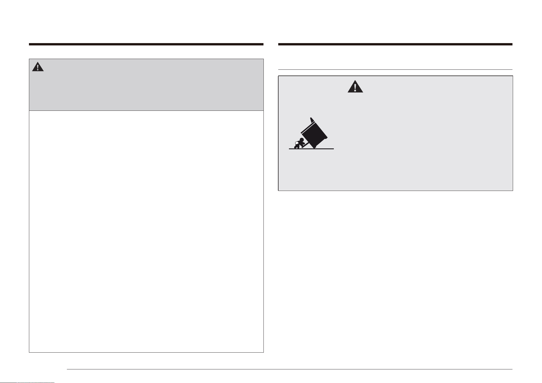
2 Español
DISPOSITIVO ANTI INCLINACIÓN
ADVERTENCIA
Peligro de caída
• Un niño o un adulto podrían inclinar la estufa y
morir.
• Instale el dispositivo anti inclinación en la estufa
y/o la estructura de acuerdo con las instrucciones de
instalación de este manual.
• Acople la estufa al dispositivo anti inclinación.
• Vuelva a acoplar el dispositivo anti inclinación en
caso de mover la estufa.
• No seguir las instrucciones puede provocar la muerte
o quemaduras graves a niños o adultos.
ADVERTENCIA
Si no se sigue la información de este manual con exactitud,
podrían producirse incendios o explosiones causantes de
daños a la propiedad, lesiones personales o muerte.
• NO almacene ni utilice gasolina u otros líquidos y vapores
inamables cerca de este u otros artefactos.
• NO guarde, coloque ni use materiales inamables o
combustibles como carbón, papel, plástico, agarradores
aislantes, ropa de cama, cortinas, gasolina u otros vapores
o líquidos inamables cerca o en el interior de la estufa.
• QUÉ HACER SI HAY OLOR A GAS:
- NO intente encender ningún artefacto.
- NO toque ningún interruptor eléctrico.
- NO utilice ningún teléfono dentro del edicio.
- Llame inmediatamente al proveedor de gas desde
el teléfono de un vecino. Siga las instrucciones del
proveedor de gas.
- Si no puede comunicarse con el proveedor de gas,
llame al departamento de bomberos.
• La instalación y el servicio técnico deben ser realizados
por un instalador calicado, agencias de servicio técnico o
el proveedor de gas.
Español 3
CARACTERÍSTICAS DE SU NUEVA ESTUFA
Mayor funcionalidad. Mejor cocción. Fácil mantenimiento. Su
nueva estufa de gas fue diseñada para brindarle estas ventajas
y aun más.
Cuanto más grande mejor
Con una capacidad de 5.8 pies cúbicos, su nueva estufa tiene
más espacio que muchas otras marcas principales en los
mercados estadounidense y canadiense. Esto signica mayor
comodidad para usted cuando cocine para festividades o
cuando reciba huéspedes.
Una cubierta con 5 quemadores
Los quemadores de potencia, los quemadores a fuego lento, así
como el quemador ovalado central ofrecen un calor de cubierta
exible para una variedad de recipientes de cocción.
El quemador ovalado central proporciona un calentamiento
parejo en grandes áreas, por lo tanto es ideal para la cocción
con comal.
Para evitar que se incline la estufa, je al piso un
dispositivo anti inclinación aprobado. (Consulte Instalación
del dispositivo anti inclinación en las Instrucciones de
instalación.) Incline cuidadosamente la estufa hacia
adelante para vericar que la instalación se haya realizado
correctamente. El dispositivo anti inclinación debe
conectarse y evitar que la estufa se incline.
Si por alguna razón se separa la estufa de la pared,
asegúrese de que vuelva a conectarse el dispositivo anti
inclinación luego de volver a colocar la estufa en su lugar.
Siga las instrucciones de instalación que se encuentran
en el Manual de instalación. No seguir estas instrucciones
puede ocasionar muerte, lesiones personales graves o
daños a la propiedad.

4 Español
Contenido
ContenidoContenido
Instrucciones de seguridad importantes 5
Símbolos de seguridad 5
California Proposición 65 Advertencia 6
Precauciones importantes de seguridad 6
Advertencias sobre el gas 11
En el estado de Massachusetts 12
Advertencias sobre la electricidad 12
Instrucciones de conexión a tierra 13
Advertencias sobre la instalación 14
Advertencias sobre los quemadores superiores 17
Advertencias acerca del horno 19
Advertencias sobre el cajón de calentamiento eléctrico o el cajón de almacenamiento inferior 21
Advertencias sobre la auto-limpieza del horno 21
Cocción correcta de carnes de res y de ave 22
Introducción a su nueva estufa 23
Descripción general 23
Supercie de cocción 26
Encendido de un quemador exterior de gas 26
Encendido manual de un quemador superior de gas 26
Selección del tamaño de la llama 26
Quemadores superiores de gas y perillas de control 26
Uso de los recipientes de cocción 27
Rejilla del quemador central 28
Rejilla para wok (SOLO NX58*565***) 28
Uso del comal 29
Funcionamiento del horno 30
Paneles de control y pantallas del horno 30
Ajuste del reloj 33
Activación/desactivación del temporizador 34
Posicionamiento de las parrillas del horno. 35
Uso de la parrilla deslizante (solo NX58*565***) 36
Abertura de ventilación del horno 37
Luz del horno 37
Hornear 38
Hornear por convección y asar al horno por convección 39
Cocción regida por temporizador 42
Cocción temporizada diferida 44
Asar a la parrilla 46
Mantener caliente 48
Cómo utilizar la función de cocción fácil 48
Modo freidora de aire (MODELO NX58*751***) 50
Cocción favorita 52
Función Shabat 54
Funciones adicionales 56
Uso del cajón de calentamiento 58
Acerca del cajón de calentamiento
(Modelo NX58*565*** solamente) 58
Encendido y apagado del cajón de calentamiento 58
Mantenimiento de su electrodoméstico 59
Cuidado y limpieza del horno 59
Cuidado y limpieza de la cubierta de cocción 63
Recambio de la luz del horno 67
Cómo retirar y volver a colocar la puerta del horno 67
Cómo retirar y volver a colocar el cajón de calentamiento
(Modelo NX58*565***) 69
Cómo retirar y volver a colocar el cajón de almacenamiento
(Modelo NX58*560***, NX58*751***) 70
Horno auto-limpiante 71
Solución de problemas 74
Solución de problemas 74
Solución de problemas y códigos de información 80
Garantía limitada (Estados Unidos) 81
Garantía (CANADÁ) 83
Español 5
Instrucciones de seguridad importantes
CONSERVE ESTAS INSTRUCCIONES
NO intentar.
NO desensamblar.
NO tocar.
Siga las instrucciones elmente.
Desenchufe el cable de alimentación del tomacorriente.
Asegúrese de que la estufa esté conectada a un
tomacorriente con cable a tierra para evitar descargas
eléctricas. Se recomienda especialmente el uso de un
tomacorriente equipado con un interruptor de falla a tierra
(GFI, por su sigla en inglés).
Comuníquese con el Centro de Servicio Técnico para
obtener ayuda. Consulte la página 85.
Nota
Estos iconos de advertencia se incluyen para evitar lesiones a
usted y a otras personas.
Obsérvelos explícitamente.
No descarte este manual. Consérvelo en un lugar seguro para
consultas futuras.
Instrucciones de seguridad importantes
LEA TODAS LAS INSTRUCCIONES ANTES DE USAR ESTE
ARTEFACTO
Todos los equipos eléctricos y de gas con piezas móviles
pueden ser peligrosos. Lea las instrucciones de seguridad
importantes para este artefacto incluidas en este manual. Las
instrucciones deben seguirse para minimizar el riesgo de lesión,
muerte o daño a la propiedad.
Guarde este manual. No lo deseche.
SÍMBOLOS DE SEGURIDAD
Signicado de iconos y símbolos en este manual del usuario:
ADVERTENCIA
Existe un riesgo de muerte o lesiones personales graves.
PRECAUCIÓN
Existe un riesgo de lesiones personales o daños a la propiedad.
PRECAUCIÓN
Para reducir el riesgo de incendio, explosión, descarga eléctrica
o lesiones personales cuando utilice su estufa de gas, siga estas
instrucciones básicas de seguridad:

6 Español
Instrucciones de seguridad importantes
Instrucciones de seguridad importantes
CONSERVE ESTAS INSTRUCCIONES
Debe conocer la ubicación de la válvula de cierre del gas y cómo
cortar éste si es necesario.
Destruya o quite adecuadamente los materiales de embalaje luego
de desembalar el artefacto.
Electricidad/mecánica
Desenchufe o desconecte la alimentación antes de realizar tareas
de mantenimiento o reparación.
No toque los controles.
Las rejillas y los comales (si están incluidos) son pesados. Pueden
ser peligrosos si se caen.
La parte interna de la parrilla dividida (si está incluida) podría
caerse accidentalmente si no se monta correctamente. Coloque
la parrilla interna en la posición adecuada dentro de la parrilla
externa.
Siempre ubique las parrillas del horno al mismo nivel en cada lado
de la cavidad. Las parrillas desniveladas podrían provocar que los
alimentos se deslicen hacia la parte inferior, lo que presenta el
riesgo de sufrir quemaduras.
CALIFORNIA PROPOSICIÓN 65 ADVERTENCIA
ADVERTENCIA
Cáncer y Daño Reproductive – www.P65Warnings.ca.gov.
PRECAUCIONES IMPORTANTES DE SEGURIDAD
ADVERTENCIA
Siga las precauciones básicas de seguridad al instalar y utilizar
esta estufa para reducir así el riesgo de incendios, descargas
eléctricas, lesiones o muerte, incluyendo lo siguiente:
Instalación y servicio técnico
Esta estufa debe instalarse correctamente y colocarse de acuerdo
con las instrucciones de instalación antes de utilizarse.
Se recomienda especialmente la instalación profesional.
Debido al tamaño y al peso de la estufa, se recomienda que dos
personas muevan o instalen este artefacto.
Todas las estufas pueden volcarse y causar lesiones graves. Instale
el dispositivo anti inclinación incluido con la estufa según las
instrucciones del Manual de instalación.
Jamás intente reparar ni reemplazar este artefacto usted mismo
a menos que este manual lo recomiende especícamente. Este
artefacto debe ser reparado únicamente por un técnico de servicio
calicado.

Español 7
Instrucciones de seguridad importantes
CONSERVE ESTAS INSTRUCCIONES
Enseñe a los niños que no deben tocar ni jugar con los controles ni
con ninguna parte de la estufa.
Recomendamos utilizar la función de bloqueo de los controles/
la puerta para reducir el riesgo de que los niños los usen
incorrectamente.
Antes de desechar la estufa, corte el cable de alimentación para
evitar que se lo conecte a una fuente de alimentación. Quite la
puerta para evitar que niños y animales puedan quedar atrapados.
Fuego
No toque los quemadores del horno, los quemadores del cajón
ni las supercies internas del horno durante o inmediatamente
después de cocinar. Las supercies de cocción, las rejillas, los
quemadores de la cubierta y las tapas, así como también las
paredes del horno, pueden estar calientes aún cuando su color sea
oscuro. Las supercies internas del horno se calientan lo suciente
como para producir quemaduras. Durante y después del uso, no
toque los quemadores del horno, los quemadores del cajón ni las
supercies internas del horno y tampoco permita que sus ropas ni
otros materiales inamables entren en contacto con ellos hasta que
haya transcurrido el tiempo suciente como para que se enfríen.
Peligro para los niños
No guarde ningún objeto que resulte de interés para los niños
sobre la cubierta o el protector posterior de la estufa. Los niños
que se trepen a la estufa para alcanzar un objeto podrían morir o
resultar seriamente lesionados.
La parrilla interna de la Parrilla Dividida puede caerse si no está
montada correctamente. Coloque la parrilla Interna en el lugar
adecuado dentro de la parrilla Externa. Siempre inserte la parrilla o
el conjunto de parrilla dividida (si está incluido) al mismo nivel del
cada lado de la cavidad del horno.
Mantenga a los niños alejados de la puerta cuando la abra o la
cierre ya que podría golpearlos o pillarles los dedos.
Mantenga todos los materiales de embalaje fuera del alcance de los
niños. Los niños pueden jugar con ellos. No desechar las bolsas de
plástico podría tener como resultado la asxia.
Los niños no deben quedar solos o sin vigilancia en el lugar donde
se utiliza la estufa. No se les debe permitir sentarse ni pararse
sobre ninguna parte de la estufa.
No permita que los niños pequeños toquen la estufa.
Las rejillas y los comales (si están incluidos) son pesados y
presentan un riesgo de lesión si se caen sobre un pie. Enséñeles a
los niños que no deben tocar ni jugar con las rejillas y los comales.

8 Español
Instrucciones de seguridad importantes
Instrucciones de seguridad importantes
CONSERVE ESTAS INSTRUCCIONES
Nunca use su estufa para ningún otro n que no sea cocinar.
Hacerlo podría tener como resultado el envenenamiento con
monóxido de carbono y el recalentamiento del horno.
No lleve prendas amplias o colgantes mientras utiliza este
electrodoméstico.
NO DEBEN ALMACENARSE NI UTILIZARSE materiales combustibles,
gasolina u otros líquidos o vapores inamables cerca de este
artefacto. Consulte QUÉ HACER SI HAY OLOR A GAS en las
Advertencias sobre el gas.
No vierta agua en el hueco de la cubierta mientras limpia la
cubierta. Esta podría ltrase en los sistemas eléctricos y de gas
de la estufa creando un riesgo de descarga eléctrica o elevados
niveles de monóxido de carbono, debido a la corrosión de las
válvulas o los puertos del gas.
No permita que los agarradores aislantes toquen un elemento
calentador caliente. No utilice una toalla ni otra tela voluminosa
como agarrador aislante.
No use la estufa para calentar recipientes de alimentos cerrados o
para secar elementos o prendas de vestir mojadas.
Mantenga los conductos de ventilación del horno libres de
obstrucciones. Limpie con frecuencia los oricios de ventilación
para evitar la acumulación de grasa. Consulte la página 37. Puede
producirse un ruido como de un ligero estallido durante la cocción
en el horno. Este sonido puede producirse durante el ciclo del
quemador normal del horno, cuando la llama del quemador del
horno se extingue.

Español 9
Instrucciones de seguridad importantes
CONSERVE ESTAS INSTRUCCIONES
Si el ciclo de auto-limpieza funciona mal, apague el horno y
desconecte la alimentación eléctrica. Consulte las páginas 81 y 82
para comunicarse con un técnico de servicio calicado.
Puede producirse un ruido como de un ligero estallido durante la
cocción en el horno.
Vapores
Sea precavido al abrir la puerta del horno. Permita la salida del
vapor o aire caliente antes de retirar o colocar los alimentos en el
horno caliente.
Utilice únicamente agarradores aislantes secos. Poner un agarrador
aislante mojado o húmedo en contacto con supercies calientes
podría producir quemaduras por vapor.
No use agua para apagar un fuego provocado por la grasa. El agua
podría causar que la grasa en llamas explote, se esparza el fuego,
se cree un incendio más grande y se genere un peligro para la
salud. Para extinguir el fuego de la materia grasa, apague la fuente
de calor y extinga el fuego con una tapa que ajuste bien o utilice un
extinguidor de incendios de polvo químico seco o de espuma para
usos diversos.
Nunca deje sin atención unidades de supercie reguladas a altas
temperaturas. Los derrames por exceso de hervor producen humo
y los derrames de sustancias grasas pueden arder en llamas.
No utilice una llama para vericar si hay pérdidas de gas. En lugar
de ello, utilice un cepillo para esparcir una mezcla de agua jabonosa
alrededor del área que está vericando. Si hay una pérdida de gas,
verá pequeñas burbujas en la mezcla de agua jabonosa en el punto
de la pérdida.
No coloque artefactos portátiles ni ningún otro objeto sobre
la cubierta, excepto cuando se trate de recipientes y utensilios
de cocina. Es posible que se produzcan daños o incendios si la
supercie está caliente.
No intente operar este artefacto si está dañado, si funciona mal o si
tiene piezas rotas o faltantes.
Jamás coloque plástico, papel u otros elementos que pudieran
derretirse o quemarse cerca de los oricios de ventilación del
horno o cualquiera de los quemadores superiores.

10 Español
Instrucciones de seguridad importantes
Instrucciones de seguridad importantes
CONSERVE ESTAS INSTRUCCIONES
• El calentamiento de bebidas puede provocar un retraso en
el punto de ebullición. Para evitar el retraso en el punto
de ebullición, SIEMPRE deje reposar las bebidas calentadas
durante al menos 20 segundos después de apagar el quemador,
para que la temperatura del líquido pueda estabilizarse. En
caso de escaldaduras, siga estas instrucciones de PRIMEROS
AUXILIOS:
- Sumerja el área escaldada en agua fría durante al menos 10
minutos
- Cúbrala con un vendaje limpio y seco
- No se aplique cremas, aceites ni lociones.
• La "marca de encendido" en el cabezal doble del quemador
debe colocarse junto al electrodo cuando se monta para evitar
una llama anormal.
• Después de encender un quemador superior, asegúrese de que
el quemador se haya encendido. Ajuste el nivel de la llama
girando la perilla del quemador.
• Cuando coloca un quemador a fuego lento, no gire la perilla del
quemador rápidamente. Mire la llama para asegurarse de que
se mantenga encendida.
Advertencias sobre los quemadores superiores
• Es posible que el cabezal del quemador se bloquee con comida
o polvo. Limpie el cabezal si parece estar bloqueado. Si limpia
el cabezal con agua, ensámblelo solo después de que esté
completamente seco. Si el cabezal está húmedo, podría impedir
que se enciendan los quemadores.
• No vierta agua sobre la cubierta para limpiarla. Puede ingresar
a la estufa y hacer que las partes internas se oxiden.
• Solo encienda los quemadores de la cubierta que tengan las
tapas en su lugar. Si las tapas de los quemadores no está en
su lugar, usted puede dañar los controles o causar un incendio
involuntario grande o peligroso.

Español 11
Instrucciones de seguridad importantes
CONSERVE ESTAS INSTRUCCIONES
Lea las instrucciones con detenimiento en
su totalidad.
La instalación de esta estufa debe cumplir con los códigos
locales o, a falta de ellos, con la versión más reciente del Código
nacional de gas combustible, ANSI Z223.1/NFPA.54. En Canadá,
la instalación debe cumplir con el Código de instalación para gas
natural CAN/CGA-B149.1 actual o con el Código de instalación para
propano CAN/CGA-B149.2 actual y con los códigos locales, cuando
corresponda. El diseño de esta estufa ha sido certicado por ETL
según la versión más reciente de ANSI Z21.1, y por Canadian Gas
Association (Asociación de Gas de Canadá) según la versión más
reciente de CAN/CGA-1.1.
No instale esta estufa en un lugar que esté expuesto a una
corriente de aire fuerte.
La instalación y el servicio técnico deben ser realizados por un
instalador calicado, agencias de servicio técnico o el proveedor de
gas.
Pídale al instalador que le muestre la ubicación de la válvula de
corte de gas y cómo cortar el suministro.
Utilice siempre conectores exibles NUEVOS cuando instale un
artefacto de gas. Jamás vuelva a utilizar los conectores exibles. El
uso de conectores exibles viejos puede causar pérdidas de gas y
lesiones personales.
ADVERTENCIAS SOBRE EL GAS
ADVERTENCIA
Si no se siguen las instrucciones de este manual con exactitud,
podrían producirse incendios o explosiones causantes de
muerte, lesiones personales o daños a la propiedad.
Si hay olor a gas:
1. Cierre la válvula y no use la estufa.
2. NO encienda cerillos, velas ni cigarrillos.
3. NO encienda ningún artefacto eléctrico o de gas.
4. NO toque ningún interruptor eléctrico ni enchufe un cable
de alimentación en un tomacorriente.
5. NO utilice ningún teléfono dentro del edicio.
6. Libere el ambiente, el edicio o el área de todos los
ocupantes.
7. Llame inmediatamente al proveedor de gas desde el
teléfono de un vecino. Siga las instrucciones del proveedor
de gas.
8. Si no puede comunicarse con el proveedor de gas, llame al
departamento de bomberos.
12 Español
Instrucciones de seguridad importantes
Instrucciones de seguridad importantes
CONSERVE ESTAS INSTRUCCIONES
EN EL ESTADO DE MASSACHUSETTS
Este producto debe ser instalado por un plomero con licencia o un
gasista matriculado o con licencia del Estado de Massachusetts.
Cuando se utilicen válvulas de bola para el cierre del gas, se debe
usar una manija en forma de “T”.
No deben conectarse varios conductos exibles de gas en serie.
ADVERTENCIAS SOBRE LA ELECTRICIDAD
Deben cumplirse las siguientes instrucciones y requisitos
eléctricos para evitar la muerte, lesiones personales por
descargas eléctricas y daños a la propiedad causados por
incendios:
1. Enchufe el artefacto a un tomacorriente de
3 clavijas conectado a tierra.
2. NO retire la clavija de conexión a tierra.
3. NO utilice un adaptador.
4. NUNCA utilice un cable prolongador.
No debe utilizar nunca este artefacto como calefactor para
calentar el ambiente. Hacerlo podría tener como resultado el
envenenamiento con monóxido de carbono y el recalentamiento
del horno.
Nunca deben bloquearse los oricios de ventilación del horno
(aberturas de aire). Ellos dejan entrar y salir el aire necesario para
que el horno funcione adecuadamente con la combustión correcta.
No se apoye sobre la estufa ya que podría girar las perillas de
control sin darse cuenta.
No se pare sobre el electrodoméstico ni coloque sobre él objetos
(como ropa sucia, fundas para hornos, velas encendidas, cigarrillos
encendidos, platos, productos químicos, objetos metálicos, etc.).
• Artículos como trapos de cocina pueden quedar enganchados
en la puerta.
• Se pueden producir descargas eléctricas, un incendio,
problemas con el producto o lesiones.

Español 13
Instrucciones de seguridad importantes
CONSERVE ESTAS INSTRUCCIONES
NUNCA conecte el cable a tierra a cañerías de plomería de
plástico, tuberías de gas o tuberías de agua caliente.
NO modique el enchufe que se provee con el artefacto.
NO coloque un fusible en el circuito neutral o de conexión a
tierra.
INSTRUCCIONES DE CONEXIÓN A TIERRA
Conexión a tierra de la estufa con un cable de conexión:
Este artefacto debe conectarse a tierra. En el caso de fallas
o averías, la conexión a tierra reducirá el riesgo de sufrir
descargas eléctricas, ya que le ofrece una ruta a la corriente
eléctrica. Este artefacto está equipado con un cable que
dispone de un enchufe con conexión a tierra. El enchufe
debe enchufarse rmemente en un tomacorriente que esté
correctamente instalado y que disponga de conexión a tierra,
de acuerdo con los códigos y ordenanzas locales.
Utilice un circuito eléctrico dedicado de CA, 120 voltios, 60
Hz, 20 A y equipado con fusibles para este artefacto. Se
recomienda un fusible de retardo o un disyuntor. NO conecte
más de un electrodoméstico a este circuito.
La estufa está equipada con un enchufe de 3 clavijas
con conexión a tierra. Este cable DEBE enchufarse a un
tomacorriente adecuado de 3 clavijas, con conexión a tierra,
que cumpla todos los códigos y ordenanzas locales. Si no está
seguro de que el tomacorriente disponga a conexión a tierra,
debe vericarlo un electricista matriculado.
Si los códigos permiten el uso de un conductor a tierra
independiente, recomendamos que un electricista calicado
determine la vía adecuada para este conductor a tierra.
El servicio eléctrico que alimentará a la estufa debe cumplir
con los códigos locales. Además de los códigos locales, debe
cumplir con la versión más reciente de ANSI/NFPA Nro. 70
(para EE.UU.) o con la versión más reciente del Código eléctrico
de Canadá CSA C22.1.
Es responsabilidad personal del propietario del
electrodoméstico brindar el servicio eléctrico correcto para
este equipo.
14 Español
Instrucciones de seguridad importantes
Instrucciones de seguridad importantes
CONSERVE ESTAS INSTRUCCIONES
ADVERTENCIA
Estos ajustes debe realizarlos un técnico de servicio calicado
de acuerdo con las instrucciones del fabricante y con todos los
códigos y requisitos de la autoridad pertinente. No seguir estas
instrucciones puede ocasionar lesiones graves o daños a la
propiedad. La agencia calicada que realice este trabajo asume
toda la responsabilidad de la conversión a gas.
No intente reparar ni reemplazar ninguna pieza de la estufa a
menos que este manual lo recomiende especícamente. Todas
las demás tareas de servicio técnico deben ser encomendadas
a un técnico calicado.
ADVERTENCIA
La conexión inadecuada del enchufe de conexión a tierra puede
tener como resultado un riesgo de descarga eléctrica. Si no está
seguro si la conexión a tierra del equipo está correctamente
realizada, consulte a un electricista calicado.
JAMÁS modique el enchufe que se provee con el artefacto.
Si no se adapta al tomacorriente existente, un electricista
calicado debe instalar uno adecuado.
ADVERTENCIAS SOBRE LA INSTALACIÓN
Un instalador calicado debería realizar la instalación y la
conexión a tierra correcta, de acuerdo con las instrucciones de
instalación. Solo instaladores de estufas de gas calicados o
técnicos de servicio deberían realizar los ajustes y el servicio
técnico.
Asegúrese de que un técnico de servicio o instalador calicado
instale y ajuste correctamente la estufa según el tipo de gas
(natural o LP) que utilizará. Para utilizar gas LP en su estufa, el
instalador debe reemplazar los 5 oricios de los quemadores
superiores y los 2 oricios del horno con el juego de oricios
para LP y también debe invertir el adaptador GPR.

Español 15
Instrucciones de seguridad importantes
CONSERVE ESTAS INSTRUCCIONES
Coloque la estufa alejada de los lugares de la cocina con
tráco y corrientes de aire para evitar una circulación de aire
insuciente.
Este artefacto debe colocarse de manera tal que se pueda
acceder al enchufe fácilmente.
No debe instalarse en un área expuesta al goteo de agua o al
aire libre.
Quite todos los materiales de embalaje de la estufa antes de
utilizarla. Estos materiales pueden prenderse fuego o causar
humo o daños por incendio.
Instale este artefacto sobre un piso nivelado y resistente que
pueda soportar el peso. Los pisos sintéticos, como el linóleo,
deben soportar temperaturas de 180 °F (82 °C) sin encogerse,
deformarse ni decolorarse. No instale nunca la estufa
directamente sobre alfombras interiores para cocinas a menos
que se coloque madera contrachapada de 0.25” o un aislante
semejante entre la estufa y la alfombra.
Este electrodoméstico debe conectarse a tierra correctamente.
Enchufe la estufa a un tomacorriente de 120 voltios con
conexión a tierra que solo se utilice para este equipo. No
retire la clavija de conexión a tierra (la tercera) del enchufe.
Enchufe rmemente el cable al tomacorriente de pared. Si no
está seguro de que el tomacorriente disponga de conexión a
tierra, es su responsabilidad y obligación personal encomendar
la instalación de un tomacorriente de tres espigas con una
conexión a tierra correcta de acuerdo con los códigos locales
y nacionales. No utilice un cable de alimentación dañado ni un
tomacorriente de pared ojo. No utilice un cable prolongador
con este electrodoméstico. Además, no utilice un adaptador
ni altere de otro modo el enchufe con conexión a tierra. Si no
tiene un tomacorriente adecuado o tiene alguna duda sobre el
tomacorriente, consulte a un electricista matriculado.

16 Español
Instrucciones de seguridad importantes
Instrucciones de seguridad importantes
CONSERVE ESTAS INSTRUCCIONES
Si se colocan gabinetes sobre la estufa, debe dejarse un
espacio libre de 40” (102 cm) entre la supercie de cocción y
la parte inferior de los gabinetes que no tengan protección.
Instale sobre la supercie de la estufa una campana de
ventilación o un horno de microondas para instalar sobre
la estufa con ventilación externa, que sea tan ancho como
la estufa y que sobresalga con respecto al frente de los
gabinetes. Consulte las instrucciones de instalación.
Retire toda la cinta y el embalaje. Asegúrese de que los
quemadores estén colocados y nivelados correctamente.
Retire los accesorios del horno y del cajón inferior.
Controle que no se hayan aojado piezas de la estufa durante
el transporte.
No tape ni bloquee las ventilaciones (aberturas de aire). Las
ventilaciones permiten la circulación de aire necesaria para
que la estufa funcione adecuadamente con la combustión
correcta. Bloquear o tapar las ventilaciones puede provocar
una combustión incorrecta que podría causar pérdidas de gas
e incendios. Las aberturas de aire están situadas detrás de la
estufa, debajo del panel de control, en las partes superior e
inferior de la puerta del horno y debajo del cajón inferior de
almacenamiento o calentamiento.
Las grandes rayaduras o los golpes fuertes en la puerta de
vidrio pueden hacer que el vidrio se rompa o estalle.
Asegúrese de que los revestimientos de las paredes que
rodean a la estufa soporten el calor, hasta 200 °F (93 °C),
generado por la estufa.
Evite colocar gabinetes sobre la estufa. Esto reduce el peligro
que plantea extender los brazos sobre las llamas descubiertas
de los quemadores en funcionamiento.
No coloque materiales combustibles ni otros productos
alrededor de la estufa.

Español 17
Instrucciones de seguridad importantes
CONSERVE ESTAS INSTRUCCIONES
Utilice siempre la posición LITE (Encender) cuando se
enciendan los quemadores superiores. Asegúrese de que los
quemadores se hayan encendido.
Si falla la ignición, gire la perilla en Off (Apagado) y espere
hasta que se disipe el gas emitido. Si mantiene la perilla en
la posición LITE (Encender) sin la ignición adecuada, el gas
emitido podría provocar una explosión.
No deje nunca los quemadores superiores sin vigilancia en la
conguración de llama HIGH (Alta). Los derrames por exceso
de hervor producen humo y los derrames de sustancias grasas
pueden arder en llamas.
Aléjese de la estufa durante la cocción mediante fritura.
Ajuste el tamaño de la llama del quemador superior para que
no sobresalga de los bordes del recipiente. Las llamas que
se extienden fuera de los bordes del recipiente pueden ser
peligrosas.
Para disminuir las salpicaduras cuando cocine alimentos con
mucho líquido, como salsa o estofado de carne, ajuste la llama
en LOW (Baja) y revuelva con frecuencia.
Utilice únicamente agarradores aislantes secos. Los
agarradores aislantes húmedos pueden liberar vapor y causar
quemaduras si entran en contacto con supercies calientes.
ADVERTENCIAS SOBRE LOS QUEMADORES
SUPERIORES
ADVERTENCIA
Siga las precauciones básicas de seguridad al instalar y utilizar
esta estufa para reducir así el riesgo de incendios, descargas
eléctricas, lesiones o muerte, incluyendo lo siguiente:
Utilice recipientes de cocción del tamaño adecuado. Evite
utilizar recipientes inestables o deformados. Seleccione
recipientes con bases planas lo sucientemente grandes
como para cubrir las rejillas de los quemadores. Para
evitar derrames, asegúrese de que los recipientes sean los
sucientemente grandes como para contener los alimentos.
Esto reducirá el tiempo de limpieza y evitará acumulaciones
peligrosas de alimentos, ya que demasiadas salpicaduras
o derrames sobre la estufa pueden incendiarse. Utilice
recipientes con manijas que puedan agarrarse fácilmente y que
permanezcan frías.
No utilice ollas o sartenes que superen el tamaño de la rejilla.
De lo contrario, las ollas o sartenes podrían perder la forma
o el color. También puede hacer que las unidades o la pared
alrededor de la rejilla se enciendan, lo que puede generar un
exceso de monóxido de carbono.

18 Español
Instrucciones de seguridad importantes
Instrucciones de seguridad importantes
CONSERVE ESTAS INSTRUCCIONES
Caliente siempre los aceites para freír en forma lenta y vigílelos a
medida que se calientan. Si se fríen alimentos a alta temperatura,
vigile cuidadosamente el proceso de cocción. Si se utilizará una
combinación de grasas y aceites durante la fritura, es necesario
revolverlos para mezclarlos antes de calentarlos. Utilice un
termómetro para freidoras de inmersión cuando sea posible.
Esto evita el recalentamiento de la freidora más allá del punto de
generación de humo. Utilice tan poco aceite como sea posible para
la fritura de inmersión. Utilizar demasiado aceite puede causar
derrames cuando se agregan los alimentos. Siempre deben retirarse
los elementos de la cubierta cuando ya no se utilicen para cocinar.
No deje elementos plásticos sobre la parte superior de la estufa. El
aire caliente de las ventilaciones en la parte superior de la estufa
puede derretir el plástico y puede causar una acumulación de
presión en recipientes de plástico cerrados. El plástico derretido
puede obstruir las ventilaciones en la parte posterior de la estufa.
Las ventilaciones obstruidas pueden provocar una combustión
incorrecta que podría causar pérdidas de gas e incendios. Puede
sufrir quemaduras graves si toca las supercies cercanas al
ventilador mientras el horno está en funcionamiento.
Mantenga todos los agarradores aislantes alejados de las
llamas abiertas cuando levante los recipientes. Jamás utilice
una toalla o una tela voluminosa como agarrador aislante.
Mantenga los plásticos alejados de los quemadores superiores
o de cualquier llama descubierta.
Cuando utilice recipientes de vidrio, asegúrese de que estén
diseñados para la cocción sobre los quemadores superiores de
las estufas.
Asegúrese siempre de que las manijas de los recipientes
queden orientadas hacia un lado o hacia la parte posterior
de la cubierta, pero nunca sobre los demás quemadores
superiores. Esto minimizará las posibilidades de quemaduras y
derrames y de que se enciendan los materiales inamables que
pueden causarse al golpear accidentalmente ollas o sartenes.
No lleve prendas amplias o colgantes mientras utiliza la estufa.
Pueden incendiarse y producirle quemaduras si tocan el
quemador superior.
Tenga cuidado de que sus manos no toquen los quemadores
cuando estén encendidos. Apague los quemadores cuando
cambie una sartén o una olla.
Español 19
Instrucciones de seguridad importantes
CONSERVE ESTAS INSTRUCCIONES
Si huele gas, corte el suministro de gas de la estufa y llame a
un técnico de servicio calicado. NUNCA utilice una llama para
encontrar la pérdida.
Siempre apague los quemadores superiores antes de retirar los
recipientes de cocción. Los controles de todos los quemadores
superiores deben estar en la posición OFF (Apagado) cuando
no se cocine.
Siempre apague los quemadores antes de ir a dormir o salir.
ADVERTENCIAS ACERCA DEL HORNO
ADVERTENCIA
NUNCA cubra los oricios ni los pasajes de la cubierta inferior
del horno. NUNCA cubra toda una parrilla del horno con papel
de aluminio o un material similar. Al cubrir la cubierta inferior o
las parrillas se obstruye el ujo de aire del horno, lo que podría
causar un envenenamiento por monóxido de carbono.
No utilice papel o cubiertas de aluminio en ninguna parte del
horno. El uso incorrecto atrapa el calor y podría causar un
peligro de incendio o daños en la estufa.
Siga siempre las instrucciones del fabricante cuando utilice
bolsas de cocción o para asar en el horno.
Esta cubierta no está diseñada para ambear alimentos ni para
cocinar con un wok o con el accesorio del aro para wok. Si se
ambean alimentos, solo debe hacerse debajo de una campana de
ventilación encendida.
Asegúrese siempre de que los alimentos
que se van a freír estén descongelados y secos. Cualquier tipo
de humedad puede causar que la grasa caliente burbujee y se
derrame del recipiente.
Jamás mueva un recipiente o freidora de inmersión que esté
llena de grasa caliente. Siempre deje que se enfríe antes de
moverlo.
Asegúrese siempre de que los controles estén en OFF
(Apagado) y de que las rejillas estén frías antes de retirarlas
para evitar cualquier posibilidad de sufrir quemaduras.
Si se coloca la estufa cerca de una ventana, JAMÁS cuelgue
cortinas largas ni persianas de papel en esa ventana. Podrían
volar sobre los quemadores superiores y prenderse fuego,
causando así un peligro de incendio.
La grasa es inamable y debe manejarse con mucho cuidado.
Nunca intente extinguir grasas encendidas con agua.

20 Español
Instrucciones de seguridad importantes
Instrucciones de seguridad importantes
CONSERVE ESTAS INSTRUCCIONES
No ase carne demasiado cerca de la llama del quemador.
Recorte el exceso de grasa de la carne antes de la cocción. La
grasa de la carne puede prenderse fuego y generar un peligro
de incendio.
Si la grasa llegara a prenderse fuego, presione la tecla Clear/
Off (Borrar/Apagar) para apagar el horno. Mantenga la puerta
del horno cerrada para extinguir el fuego.
Siempre se debe hornear o asar con la puerta del horno
cerrada. Si se asa con la puerta parcial o completamente
abierta se pueden dañar las perillas de control del quemador
exterior o incluso la mesada de la cocina.
Mantenga el área del artefacto desocupada y libre de
materiales combustibles, gasolina y otros vapores y líquidos
inamables.
No utilice el horno para secar papeles o ropa, etc. Si se
recalientan, estos elementos podrían prenderse fuego.
NO limpie la junta selladora de la puerta. La junta de la puerta
es esencial para lograr que el horno quede bien sellado. Se
debe tener cuidado de no dañar ni mover la junta.
No golpee el vidrio del horno. No rocíe agua en el vidrio del
horno cuando el horno esté encendido o apenas haya apagado
el horno.
Sepárese de la estufa cuando abra la puerta de un horno
caliente. El aire caliente que sale y el vapor puede causar
quemaduras.
No utilice el horno como lugar de almacenamiento. Los
elementos almacenados pueden dañarse o prenderse fuego.
Mantenga el horno libre acumulaciones de grasa.
Cambie de posición las parrillas del horno solo cuando el horno
esté frío para evitar quemaduras o lesiones personales.
No caliente envases que no hayan sido abiertos. La presión
en el recipiente podría acumularse y causar una explosión o
lesiones personales.
Utilice solo recipientes de vidrio recomendados para hornos de
gas.
Esto evita que la grasa acumulada se encienda.
Español 21
Instrucciones de seguridad importantes
CONSERVE ESTAS INSTRUCCIONES
No use el cajón inferior/de calentamiento en el horno superior.
No coloque el cajón inferior/de calentamiento en el horno
superior durante un ciclo de auto-limpieza.
No deje recipientes de grasa derretida en el cajón inferior o
cerca de él.
No deje ni almacene productos de papel, plásticos, alimentos
enlatados ni materiales combustibles dentro del cajón. No
utilice el cajón para secar periódicos. Podrían prenderse fuego.
Los elementos de plástico podrían derretirse.
ADVERTENCIAS SOBRE LA AUTOLIMPIEZA DEL
HORNO
ADVERTENCIA
Siga las precauciones básicas de seguridad al instalar y utilizar
esta estufa para reducir así el riesgo de incendios, descargas
eléctricas, lesiones o muerte, incluyendo lo siguiente:
No deje niños sin vigilancia cerca de la estufa durante el ciclo
de auto-limpieza. Las supercies exteriores de la estufa se
calientan lo suciente como para producir quemaduras si se
tocan.
ADVERTENCIAS SOBRE EL CAJÓN DE
CALENTAMIENTO ELÉCTRICO O EL CAJÓN DE
ALMACENAMIENTO INFERIOR
El cajón de calentamiento está diseñado para mantener los
alimentos cocinados calientes a la temperatura adecuada
para servirlos. Siempre comience con alimentos calientes. No
pueden calentarse, entibiarse ni cocinarse alimentos fríos o a
temperatura ambiente en el cajón de calentamiento.
No toque la supercie interior del cajón ni el elemento de
calentamiento. Es posible que estas supercies estén calientes
y podrían ocasionarle quemaduras.
Sea precavido al abrir el cajón. El vapor o aire caliente que
escapen pueden producir quemaduras o lesiones personales.
No utilice papel de aluminio para revestir el cajón inferior. El
papel de aluminio atrapará el calor y modicará el rendimiento
del calentamiento del cajón. Además, podría dañar el acabado
interior.

22 Español
Instrucciones de seguridad importantes
Instrucciones de seguridad importantes
CONSERVE ESTAS INSTRUCCIONES
Se deben retirar los estantes de horno niquelados del horno
durante el ciclo de auto-limpieza. Los estantes de horno
recubiertos con porcelana pueden limpiarse en el horno
durante el ciclo de auto-limpieza.
COCCIÓN CORRECTA DE CARNES DE RES Y DE AVE
Asegúrese de que todas las carnes de res y de ave se
cocinen bien. La carne de res debe cocinarse siempre a
una temperatura interna de 160 °F (71 °C). La carne de ave
debe cocinarse siempre a una temperatura interna de
180 °F (82 °C). Cocinar estos alimentos a estas
temperaturas mínimamente seguras puede contribuir
a que usted y su familia queden protegidos contra las
enfermedades transmitidas por los alimentos.
Aléjese de la estufa cuando abra la puerta del horno después
de un ciclo de auto-limpieza. El horno estará MUY CALIENTE
y el vapor y el aire caliente que escapen pueden producir
quemaduras.
Retire todas las parrillas y los demás utensilios del horno antes
de comenzar un ciclo de auto-limpieza. Las parrillas del horno
pueden dañarse y los objetos extraños podrían prenderse
fuego si quedan dentro de la cavidad del horno.
Limpie los derrames excesivos antes de realizar la operación
de auto-limpieza.
Retire todos los recipientes, sondas del horno y cualquier papel
de aluminio antes de realizar la operación de auto-limpieza.
Nunca realice la auto-limpieza si el cajón inferior o el
recipiente del cajón están en el horno.
Si la operación de auto-limpieza funciona mal, apague el horno,
desconecte el suministro eléctrico y comuníquese con un
técnico de servicio calicado.
No utilice limpiadores de hornos. Los limpiadores comerciales
de hornos o los forros para hornos no deben utilizarse JAMÁS
en el horno ni alrededor de ninguna de sus partes. Los residuos
de los limpiadores de hornos dañarán el interior del horno
durante la operación de auto-limpieza.
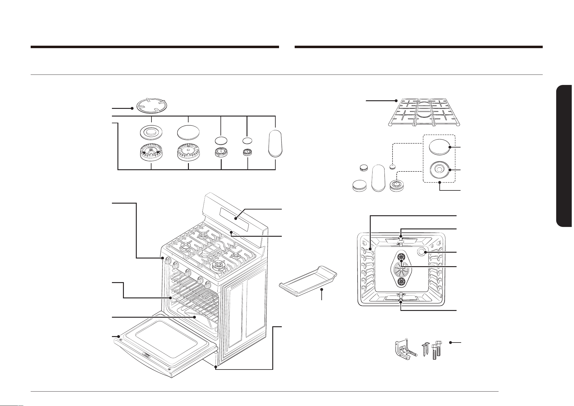
Español 23
Introducción a su nueva estufa
Introducción a su nueva estufa
Descripción general
MODELO NX58*565***
* Wok traducción
* Tapas de quemadores de la cubierta
Quemadores de la cubierta
Cabezales de quemadores de la
cubierta (5)
Tazas de quemadores de la cubierta (5)
(no se muestran debajo de los
quemadores)
Electrodos (5)
(no se muestran debajo de los
quemadores)
COMPONENTES DE LA CUBIERTA DE
COCCIÓN
Rejillas de fundición continua para
uso intenso
- * Rejilla del quemador izquierdo
- * Rejilla del quemador central
- * Rejilla del quemador derecho
Nota: las rejillas izquierda y derecha
pueden utilizarse de manera
intercambiable.
* Perillas de control de quemadores de
la cubierta (5)
- Control del quemador delantero
izquierdo
- Control del quemador trasero
izquierdo
- Control del quemador central
- Control del quemador trasero derecho
- Control del quemador delantero
derecho
COMPONENTES DEL HORNO
* Parrillas del horno (2)
Parrilla deslizante (1)
(según como esté equipado)
Piso del horno desmontable
PANTALLA
Supercie plana
Línea cóncava
Uso común
COMPONENTES DEL HORNO
Guía de posiciones de las parrillas
del horno
Quemador del horno para asar a la
parrilla
* Luz del horno (1)
Quemador del horno para hornear
PATAS NIVELADORAS AJUSTABLES (4)
(no se muestran)
KIT DE MÉNSULAS
ANTI-INCLINACIÓN (1)
Ventilador de convección (1)
Calentador de convección
(no se muestra)
Comal (1)
ABERTURA DE VENTILACIÓN
DEL HORNO
(centrada debajo del panel de
control del horno)
COMPONENTES DEL CAJÓN DE CALENTAMIENTO
Cajón de calentamiento desmontable (1)
Rieles de la guía giratoria de extensión
completa (2)
Elemento calentador eléctrico
(no se muestra debajo del cajón)
Puerta del horno desmontable
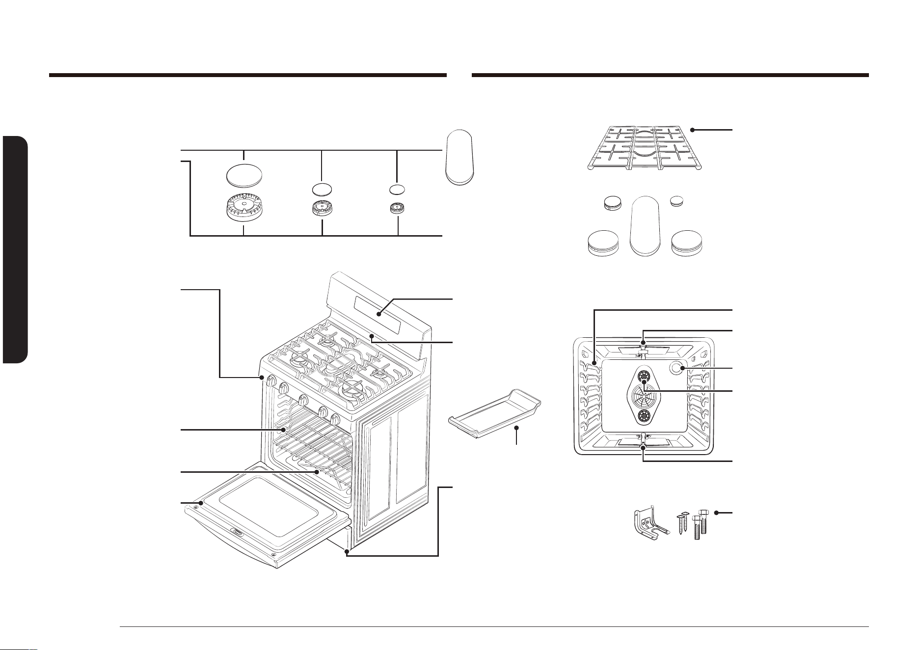
24 Español
Introducción a su nueva estufa
Introducción a su nueva estufa
MODEL NX58*560***
*Tapas de quemadores de la cubierta
Quemadores de la cubierta
Cabezales de quemadores de la
cubierta (5)
Tazas de quemadores de la
cubierta (5)
(no se muestran debajo de los
quemadores)
Electrodos (5)
(no se muestran debajo de los
quemadores)
COMPONENTES DE LA CUBIERTA DE
COCCIÓN
Rejillas de fundición continua para uso
intenso
- *Rejilla del quemador izquierdo
- *Rejilla del quemador central
- *Rejilla del quemador derecho
*Perillas de control de quemadores de la
cubierta (5)
- Control del quemador delantero
izquierdo
- Control del quemador trasero izquierdo
- Control del quemador central
- Control del quemador trasero derecho
- Control del quemador delantero
derecho
COMPONENTES DEL HORNO
*Parrillas de horno (2)
Parte inferior desmontable del horno
PANTALLA
COMPONENTES DEL HORNO
Guía de posiciones de las parrillas del
horno
Quemador del horno para asar a la
parrilla
*Luz del horno (1)
Quemador del horno para hornear
PATAS NIVELADORAS AJUSTABLES (4)
(no se muestran)
KIT DE MÉNSULAS ANTI-INCLINACIÓN (1)
Ventilador de convección (1)
Comal (1)
ABERTURA DE VENTILACIÓN
DEL HORNO
(centrada debajo del panel de
control del horno)
COMPONENTES DEL CAJÓN DE
ALMACENAMIENTO
Cajón de almacenamiento desmontable (1)
Puerta del horno desmontable
Si necesita alguno de los accesorios identicados con un * (asterisco), comuníquese con el Centro de llamados de Samsung al número que gura en la última página o visite
nuestro sitio en línea de repuestos www.samsungparts.com.
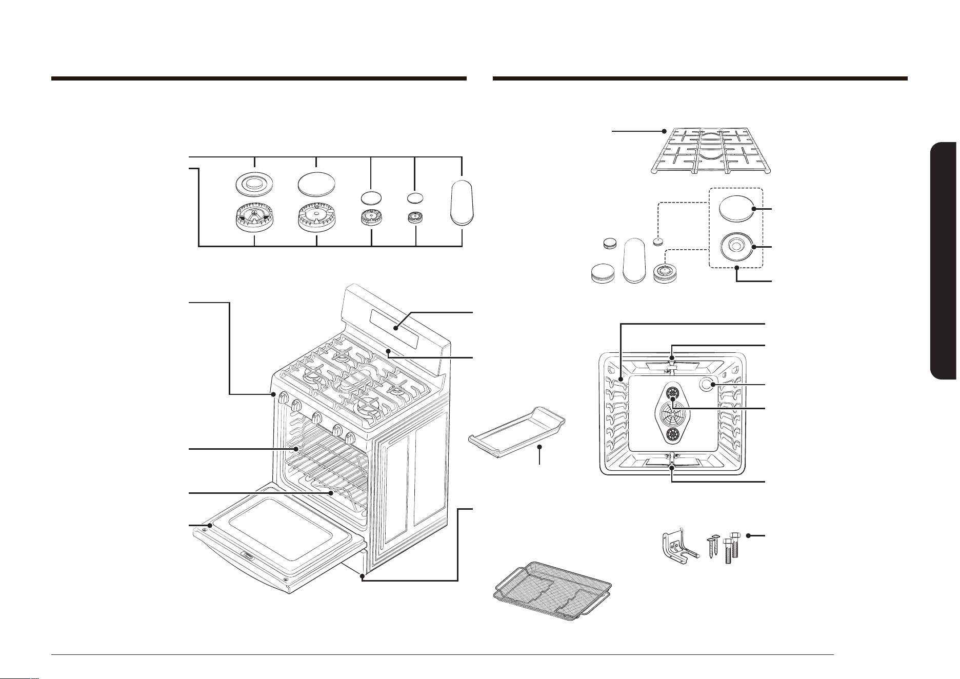
Español 25
Introducción a su nueva estufa
MODEL NX58*751***
*Tapas de quemadores de la cubierta
Quemadores de la cubierta
Cabezales de quemadores de la
cubierta (5)
Tazas de quemadores de la
cubierta (5)
(no se muestran debajo de los
quemadores)
Electrodos (5)
(no se muestran debajo de los
quemadores)
*Perillas de control de quemadores de la
cubierta (5)
- Control del quemador delantero
izquierdo
- Control del quemador trasero izquierdo
- Control del quemador central
- Control del quemador trasero derecho
- Control del quemador delantero
derecho
COMPONENTES DEL HORNO
*Parrillas de horno (2)
Parte inferior desmontable del horno
PANTALLA
COMPONENTES DEL HORNO
Guía de posiciones de las parrillas del
horno
Quemador del horno para asar a la
parrilla
*Luz del horno (1)
Quemador del horno para hornear
PATAS NIVELADORAS AJUSTABLES (4)
(no se muestran)
KIT DE MÉNSULAS ANTI-INCLINACIÓN (1)
Ventilador de convección (1)
Comal (1)
ABERTURA DE VENTILACIÓN
DEL HORNO
(centrada debajo del panel de
control del horno)
COMPONENTES DEL CAJÓN DE
ALMACENAMIENTO
Cajón de almacenamiento desmontable (1)
Puerta del horno desmontable
COMPONENTES DE LA CUBIERTA DE
COCCIÓN
Rejillas de fundición continua para
uso intenso
- * Rejilla del quemador izquierdo
- * Rejilla del quemador central
- * Rejilla del quemador derecho
Nota: las rejillas izquierda y derecha
pueden utilizarse de manera
intercambiable.
Supercie plana
Línea cóncava
Uso común
Bandeja de la freidora de aire (1)
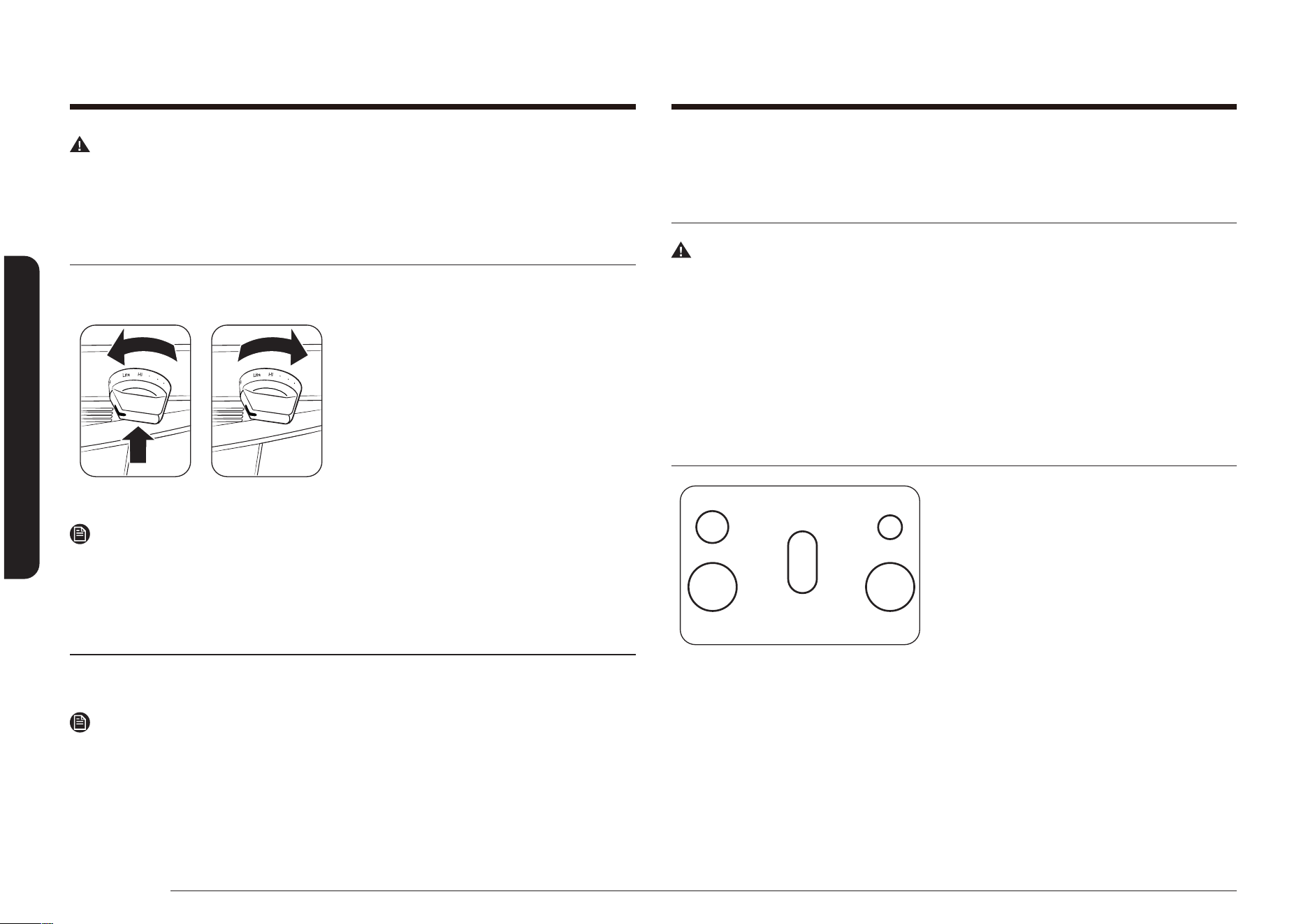
26 Español
Supercie de cocción
Supercie de cocciónSupercie de cocción
ADVERTENCIA
ANTES DE USAR LOS QUEMADORES SUPERIORES, asegúrese de seguir todas las
advertencias y precauciones de seguridad enumeradas en la página 6. No hacerlo
podría dañar el producto, causar lesiones personales o incluso la muerte.
Encendido de un quemador exterior de gas
Asegúrese de que todos los quemadores superiores estén ubicados y montados
correctamente.
1. Empuje la perilla de control y gírela a la
posición LITE (Encender). Oirá un “clic”
que indica que el sistema de ignición
electrónico funciona correctamente.
2. Una vez encendido el quemador
exterior, gire la perilla de control
para ajustar la potencia del quemador
y apagar el sistema de ignición
electrónico.
Nota
Recomendamos usar el quemador del lado trasero izquierdo para cocinar salsa
de tomate a fuego lento y el quemador del lado trasero derecho para derretir
chocolate.
Encendido manual de un quemador superior de gas
Si se produce un corte de energía eléctrica, los quemadores superiores igualmente
pueden encenderse en forma manual.
Nota
Utilice una precaución extrema cuando encienda un quemador exterior en forma
manual.
1. Lleve un encendedor de la parrilla de gas largo al quemador superior que
desea encender.
2. Empuje la perilla de control correspondiente al quemador y gírela a la posición
LITE (Encender).
3. Una vez que se encendió el quemador, coloque la perilla de control y el
quemador en el ajuste deseado.
Selección del tamaño de la llama
ADVERTENCIA
Las llamas más grandes que la base de los recipientes de cocción no calentarán
más rápido, sino que podrían causar un peligro de incendio o lesión personal.
Las llamas de los quemadores siempre deben permanecer debajo de los
recipientes de cocción. Las llamas nunca deben extenderse más allá de la base o de
los laterales de los recipientes de cocción.
Siempre mire las llamas cuando ajuste el calor con las perillas de control. Las
llamas siempre deben coincidir con el tamaño del recipiente que se está utilizando.
Quemadores superiores de gas y perillas de control
TI TD
DI DD
CENTRO
La cubierta de su estufa de gas tiene cinco
quemadores de gas. Todos los quemadores
de cubierta sellados tienen un diseño de
puerto abierto que ofrece un ensamble fácil
y un funcionamiento preciso y conable.
Los distintos tamaños de quemadores
aseguran que tenga la fuente de calor
adecuada para la cocción deseada.
El quemador trasero derecho ofrece un desempeño de cocción preciso para
alimentos delicados y alimentos que requieren un ajuste de calor bajo para
tiempos de cocción prolongados. El quemador trasero derecho le permite usar el
ajuste LO (Bajo) para un ajuste de cocción a fuego lento muy bajo.
Los quemadores traseros izquierdo y central son quemadores de uso general
que pueden utilizarse para la mayoría de las cocciones. Los ajustes HI (Alto) a
LO (Bajo) ofrecen una amplia gama de temperaturas de cocción para cumplir sus
necesidades de cocción.
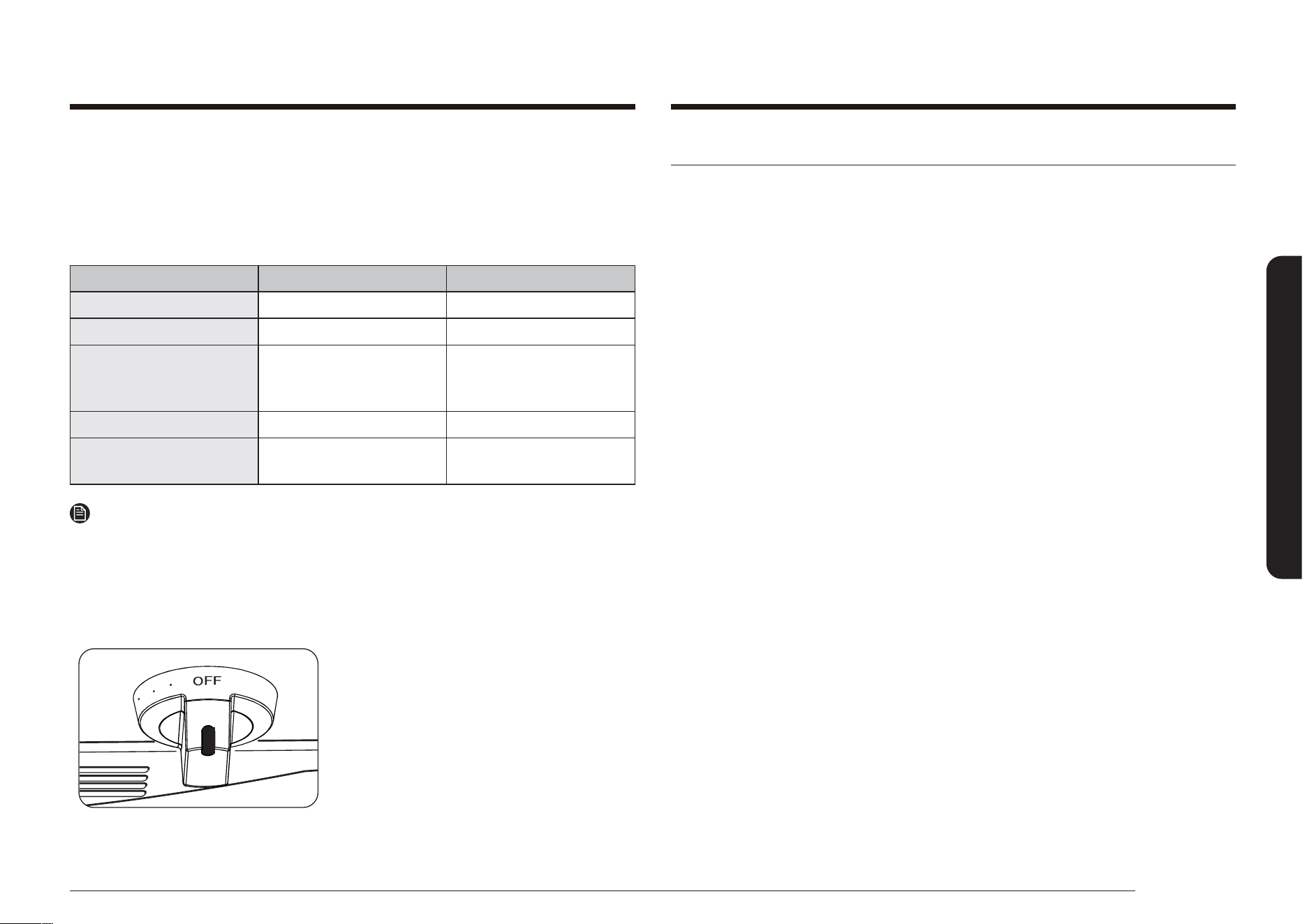
Español 27
Supercie de cocción
Uso de los recipientes de cocción
Utilizar los recipientes de cocción correctos puede evitar muchos problemas,
tales como cocción despareja o tiempos de cocción demasiado largos. Utilizar
las cacerolas y sartenes adecuadas redundará en menor tiempo de cocción y los
alimentos se cocinarán en forma más pareja. Busque las siguientes características
en las ollas:
• Fondo plano y lados verticales.
• Tapa bien ajustada.
• El peso del mango no inclina el recipiente.
• El recipiente está bien equilibrado.
• El tamaño del recipiente guarda adecuada relación con la cantidad de alimento
que se prepara y con el quemador superior.
• Hecho de un material que es buen conductor del calor.
• El diámetro del recipiente corresponde con el diámetro de la llama del
quemador superior.
El material del que están hechos sus recipientes de cocción determina que tan
rápida y uniformemente se transere el calor del quemador superior al fondo del
recipiente.
ALUMINIO: Excelente conductor de calor. Algunos tipos de alimentos causarán
el oscurecimiento del aluminio. (Los recipientes de aluminio anodizado son
resistentes a las manchas y a las picaduras).
COBRE: Excelente conductor de calor pero su color se altera con facilidad.
ACERO INOXIDABLE: Lento conductor de calor, los resultados de cocción pueden
ser desparejos. Es duradero, fácil de limpiar y resistente a las manchas.
HIERRO FUNDIDO: Mal conductor de calor, pero retiene muy bien el calor. Una vez
alcanzada la temperatura necesaria, produce cocción uniforme.
UTENSILIOS ESMALTADOS: Las características de conducción de calor dependerán
del material base.
VIDRIO: Conductor de calor lento. Los recipientes de cocción de vidrio están
diseñados para dos usos: cocción sobre los quemadores superiores de las estufas
o uso en el horno. Solo use los recipientes de cocción en el lugar para el que se
diseñaron.
Los quemadores delanteros derecho e izquierdo ofrecen la máxima potencia. Estos
quemadores también pueden utilizarse como quemadores de uso general, pero
están diseñados para ofrecer un calor rápido para recipientes de cocción grandes.
Los quemadores delanteros derecho e izquierdo esparcen el calor con un círculo de
llamas más grande. Esto ofrece una mejor distribución del calor para recipientes
de cocción más grandes (12”/30.5 cm) u ollas y sartenes más grandes.
POSICIÓN DEL QUEMADOR FUNCIÓN TIPO DE ALIMENTO
DELANTERO DERECHO (DD) Calentamiento rápido Comida hervida
TRASERO DERECHO (TD) Cocción a fuego lento baja Chocolate, guisos, salsas
CENTRO Cocción con comal
Panqueques, hamburguesas,
huevos fritos, sándwiches
calientes
DELANTERO IZQUIERDO (DI) Calentamiento rápido Comida hervida
TRASERO IZQUIERDO (TI)
Calentamiento general
Cocción a fuego lento baja
Alimentos en general
Salsa de tomate*, guisos
Nota
* La salsa de tomate debe revolverse durante la cocción a fuego lento baja.
El quemador ovalado central también puede utilizarse para ollas y sartenes
grandes, pero está diseñado para usarse con la rejilla del quemador central o el
accesorio de comal central (si está incluido). El quemador ovalado esparce el calor
de manera más pareja sobre el área de cocción central más grande.
Cada quemador superior tiene una perilla de
control con ajustes de HI (Alto) a LO (Bajo).
También tienen un ajuste LITE (Encender)
que solo se utiliza para encender la llama.
El sistema de encendido electrónico hace
chispas cuando la perilla de control está en
posición LITE (Encender).
El indicador de quemadores superiores
junto a la perilla de control muestra qué
quemador controla la perilla.
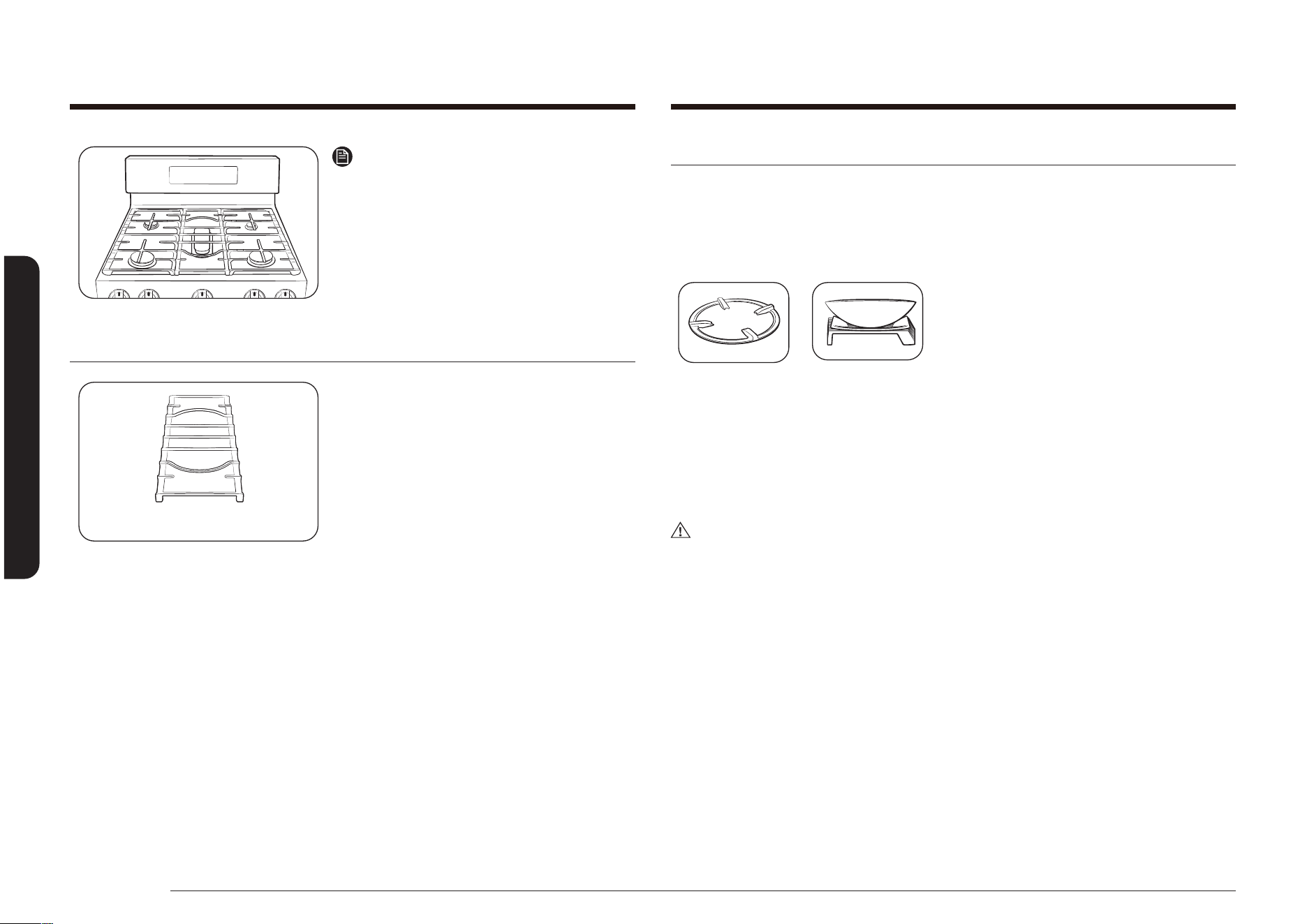
28 Español
Supercie de cocción
Supercie de cocción
Rejilla para wok (SOLO NX58*565***)
Los woks se utilizan con frecuencia para salteados, fritura en sartén, fritura de
inmersión y escalfado.
La rejilla para wok proporcionada puede soportar una olla o un wok de 12 a 14”.
CÓMO USAR LA REJILLA PARA WOK
1. Antes de colocar la rejilla para wok,
asegúrese de que el quemador esté
apagado y la parrilla completamente
fría.
2. Coloque la rejilla para wok sobre
cualquiera de las rejillas laterales.
3. Coloque el wok sobre la rejilla para wok.
(Asegúrese de que el wok se asiente
rmemente sobre la rejilla.)
4. Encienda el quemador y ajuste el nivel
de la llama.
PRECAUCIÓN
• No quite la rejilla para wok hasta que las rejillas de la cubierta, las supercies
y la rejilla para wok se hayan enfriado completamente.
• Cuando se utiliza la cubierta, el horno o los sistemas de asado a la parrilla, la
rejilla para wok que se encuentra sobre la cubierta puede calentarse mucho.
Siempre use guantes para horno cuando coloque o quite la rejilla para wok.
• No utilice una olla o sartén con un fondo plano o con un diámetro inferior al
diámetro del aro para wok. De lo contrario, la olla o sartén podría volcarse.
• No utilice sobre la rejilla para wok una sartén o una olla con un fondo plano,
o un wok con un diámetro inferior al diámetro del aro para wok. Si lo hace, la
sartén, la olla o el wok podrían volcarse.
• El uso de un wok de mayor tamaño podría provocar que las llamas se esparzan
y dañen la supercie de cocción circundante.
Nota
No coloque una olla o sartén pequeña con
un diámetro de fondo de alrededor de 6” o
menos en la rejilla central. La olla o la sartén
podrían volcarse. Recomendamos colocar
ollas o sartenes de tamaño pequeño en la
parte trasera de cada rejilla lateral.
Rejilla del quemador central
Rejilla del quemador central
Las estufas de gas Samsung vienen con una
rejilla para el quemador central. Esta rejilla
calza sobre el quemador ovalado central.
La rejilla del quemador central no debe
colocarse sobre ningún otro quemador y no
debe utilizarse ninguna otra rejilla central
en esta estufa.
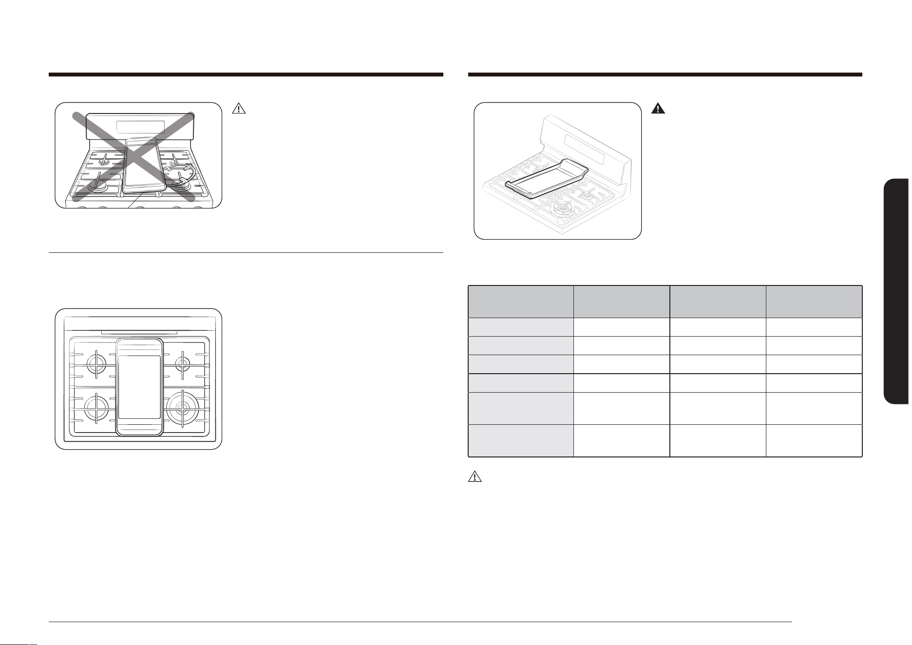
Español 29
Supercie de cocción
Advertencia
NO quite la rejilla central cuando utilice el
comal.
Cómo cocinar: Precaliente el comal de acuerdo con la guía que se encuentra a
continuación y ajuste las condiciones de cocción.
Tipo de alimento
Tiempo de
precalentamiento
Condición de
precalentamiento
Condición de
cocción
Panqueques 5 min. 5 (mediana alta) 4 (mediana)
Hamburguesas 5 min. 7 (alta) 5 (mediana alta)
Huevos fritos 5 min. 7 (alta) 5 (mediana baja)
Tocino - Ninguna 4 (mediana)
Salchichas para el
desayuno
5 min. 7 (alta) 5 (mediana)
Emparedado de
queso grillado
4 min. 7 (alta) 6 (mediana alta)
PRECAUCIÓN
• NO quite el comal hasta que las rejillas de la cubierta, las supercies y el comal
se hayan enfriado completamente.
• El comal que se encuentra sobre la cubierta puede calentarse mucho cuando se
utilizan la cubierta, el horno o el sistema de asado a la plancha. Utilice siempre
guantes cuando coloque o quite el comal.
PRECAUCIÓN
No utilice la rejilla para wok con el comal al
mismo tiempo.
Uso del comal
El comal recubierto móvil ofrece una supercie de cocción extra grande para
cocinar carnes, panqueques o los demás alimentos que generalmente se preparan
en sartenes.
Cómo colocar el comal: El comal solo puede
utilizarse con el quemador central. Debe
colocarse correctamente sobre la parrilla
central, tal como lo indica la gura que se
encuentra a continuación.
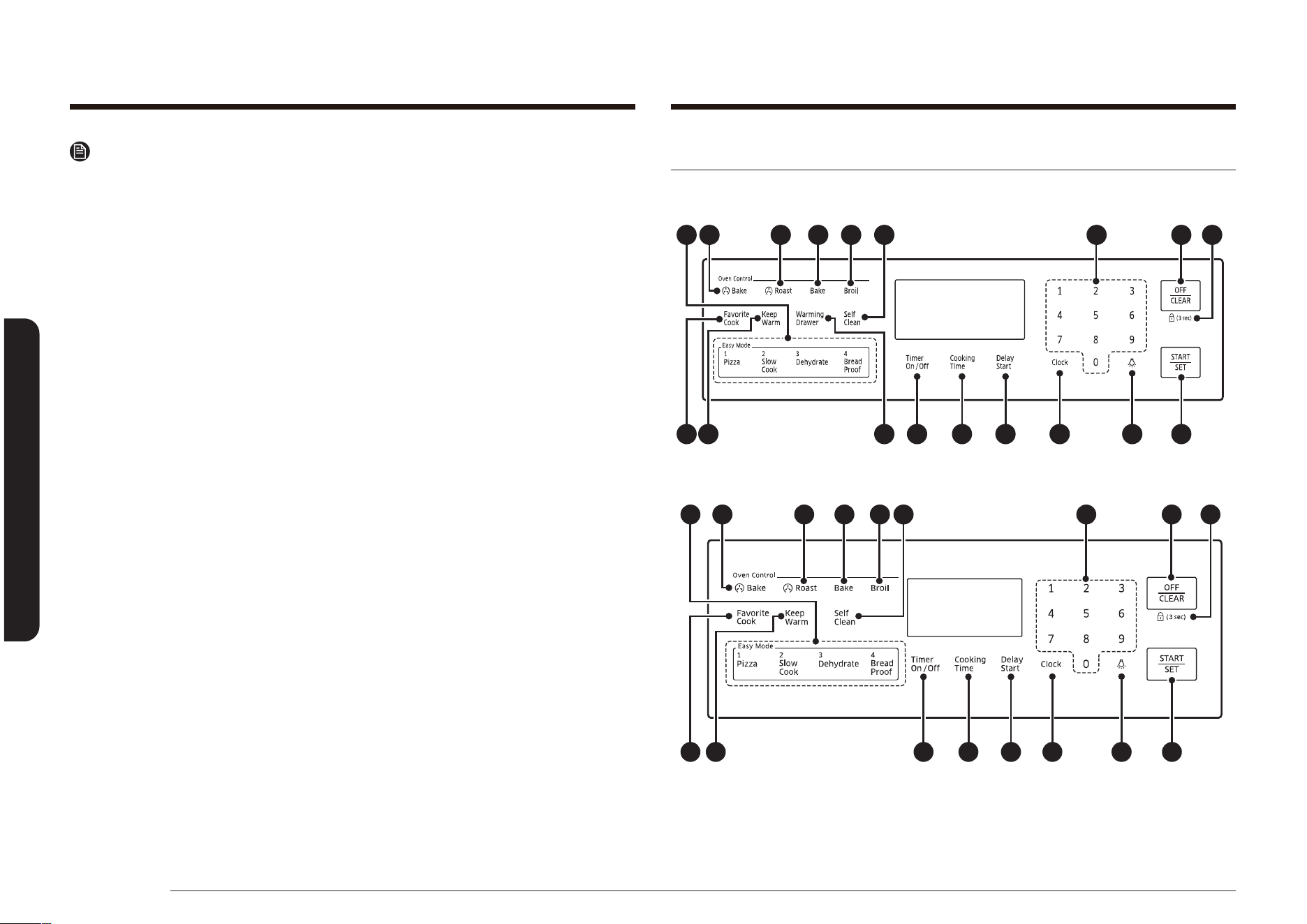
30 Español
Funcionamiento del horno
Funcionamiento del horno Funcionamiento del horno
Paneles de control y pantallas del horno
MODELO NX58*565***
03 04 05 09 07
15 14 16 17 18 06
08
12
11
13
01 02
10
MODELO NX58*560***
03 04 05 09 07
15 14 16 17 18 06
0802
12 10
01 11
Nota
• Coloque cuidadosamente el comal sobre la rejilla central.
• Es posible que deban ajustarse las conguraciones del comal si se lo utiliza
durante un plazo extenso.
• El comal se decolorará con el transcurso del tiempo a medida que se cure con
el uso.
• Después de utilizar el comal, déjelo enfriar antes de guardarlo.
Nota importante:
• NO recaliente el comal. Ello puede dañar el recubrimiento que no esté
adherido.
• NO utilice utensilios de metal que puedan dañar la supercie del comal. No
utilice el comal como tabla para cortar.
• NO coloque ni almacene objetos sobre el comal.
• NO dé vuelta al comal ni utilice la parte inferior para cocinar. Utilice
únicamente la parte superior del comal.
• NO utilice el comal para otro n que no sea cocinar.
• Evite cocinar alimentos extremadamente grasosos. Pueden ocurrir derrames.
• El comal puede calentarse cuando se utilizan los quemadores que lo rodean.

Español 31
Funcionamiento del horno
Nota
Todos los hornos se controlan con teclas táctiles electrónicas. Utilice las siguientes
teclas para programar y operar todas las funciones de cocción, limpieza y
temporización del horno. Todos los ajustes programados y los estados de cocción
se mostrarán en la pantalla digital.
Controles de las funciones especiales, del horno y del tiempo
01 EASY COOK (COCCIÓN FÁCIL): Presione para recuperar el ajuste de la receta de
cocción fácil del horno.
02 CONVECTION BAKE (HORNEAR POR CONVECCIÓN)( ): Activa la función de
horneado por convección. Use esta función para hornear cantidades grandes
en varios estantes al mismo tiempo.
03 CONVECTION ROAST (ASAR POR CONVECCIÓN)( ):Activa la función de asar
por convección. Use esta función para asar cortes de carne grandes.
04 BAKE (HORNEAR): Toque esta tecla para activar la función de hornear. Cocina
alimentos uniformemente mediante el quemador inferior del horno.
05 BROIL (ASAR A LA PARRILLA):Activa la función de asar a la parrilla. Asa los
alimentos solamente con el quemador superior del horno.
06 START/SET (INICIO/CONFIGURAR): Toque esta tecla para iniciar las funciones de
cocción, limpieza y temporizador del horno.
07 OFF/CLEAR (APAGAR/BORRAR): Presione para cancelar todas las operaciones
del horno excepto reloj y temporizador.
08 HOLD 3 SEC (MANTENER 3 SEG.): Desactiva el panel de control táctil para
evitar que el horno se encienda accidentalmente. También bloquea la puerta
del horno para impedir un vuelco accidental de la estufa. Las teclas táctiles
no funcionarán y la puerta del horno permanecerá bloqueada hasta que se
desactive esta opción.
09 TECLADO NUMÉRICO: Toque estas teclas para establecer los tiempos, las
temperaturas y las funciones programadas del horno.
10 KEEP WARM (MANTENER CALIENTE): Toque esta tecla para mantener los
alimentos calientes tras la cocción. Reduce la temperatura del horno y la
mantiene entre 150 °F y 200 °F (66 °C y 93 °C).
11 SELF CLEAN (AUTO-LIMPIEZA): Activa la función de auto-limpieza del horno.
Usa una temperatura muy alta para quemar la suciedad interna del horno.
MODELO NX58*751***
03 04 05 09 07
15 14 16 17 18 06
0802
12 10
01 11
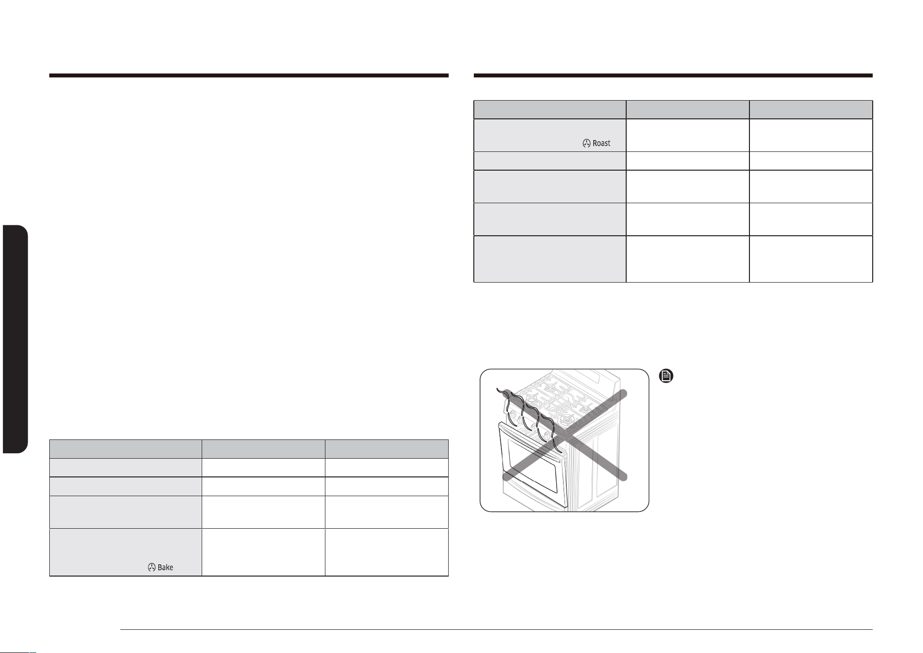
32 Español
Funcionamiento del horno
Funcionamiento del horno
FUNCIÓN VALOR MÍNIMO VALOR MÁXIMO
CONVECTION ROAST (ASAR
POR CONVECCIÓN) ( )
150 °F (66 °C) 550 °F (288 °C)
AIR FRY (FREIDORA DE AIRE) 350 °F (177 °C) 500 °F (260 °C)
KEEP WARM
(MANTENER CALIENTE)
- 3 horas
WARMING DRAWER
(
CAJÓN DE CALENTAMIENTO
) *
- 3 horas
BREAD PROOF
(ENTIBIAR PAN PARA
LEUDADO)
- 12 horas
* Solo modelo NX58*565***
En el caso de congurar Conversion On (Conversión activada) para Hornear por
convección y/o Asar por convección, puede ajustar la temperatura mínima en
175 °F (79 °C).
Nota
Siempre se debe hornear o asar con la
puerta del horno cerrada.
Si deja la puerta del horno abierta
mientras el horno está en funcionamiento,
el quemador del horno se detendrá en
1 minuto. No es una falla del producto.
Cuando cierre la puerta el horno,
se pondrá en marcha automáticamente.
Modo de aplicación: Conv. Bake (Hornear
por convección), Conv. Roast (Asar por
convección), Bake (Hornear), Broil (Asar
a la parrilla), Pizza, Slow Cook (Cocción
lenta), Dehydrate (Deshidratar), Bread Proof
(Entibiar pan para leudado), Favorite Cook
(Cocción favorita), Air Fry (Freidora de aire).
12 FAVORITE COOK (COCCIÓN FAVORITA): Activa la función de cocción favorita.
Esta función permite programar hasta tres ciclos de cocción utilizados con
mayor frecuencia para poder establecerlos e iniciarlos tocando solamente un
botón.
13 WARMING DRAWER (CAJÓN DE CALENTAMIENTO) (MODELO NX58*565***):
Toque esta tecla para activar la función del cajón de calentamiento.
El elemento calentador eléctrico que se encuentra debajo del cajón utiliza tres
ajustes para mantener los alimentos calientes.
14 COOKING TIME (TIEMPO DE COCCIÓN): Toque esta tecla y luego establezca el
tiempo de cocción que desea. El horno se apagará automáticamente una vez
transcurrido el tiempo establecido.
15 TIMER ON/OFF (ACTIVAR/DESACTIVAR TEMPORIZADOR): Toque para
seleccionar la función del temporizador. Activa el temporizador de cocina
según el tiempo deseado.
16 DELAY START (INICIO RETARDADO): Permite establecer que el horno se inicie y
se detenga automáticamente. Use con las funciones Bake (Hornear), Convection
Bake (Hornear por convección), Convection Roast (Asar por convección), Cook
Time (Tiempo de cocción) o Self Clean (Auto-limpieza).
17 CLOCK (Reloj): Permite ajustar el reloj.
18 LUZ DEL HORNO: Toque esta tecla para encender o apagar la luz del horno.
VALORES AJUSTABLES MÍNIMOS Y MÁXIMOS
Todas las funciones enumeradas en la siguiente tabla tienen valores ajustables
mínimos y máximos de temperatura o de tiempo.
FUNCIÓN VALOR MÍNIMO VALOR MÁXIMO
BAKE (HORNEAR) 150 °F (66 °C) 550 °F (288 °C)
BROIL (ASAR A LA PARRILLA) Baja Alta
SELF CLEAN
(AUTO-LIMPIEZA)
2 horas 4 horas
CONVECTION BAKE
(HORNEAR POR
CONVECCIÓN) ( )
150 °F (66 °C) 550 °F (288 °C)
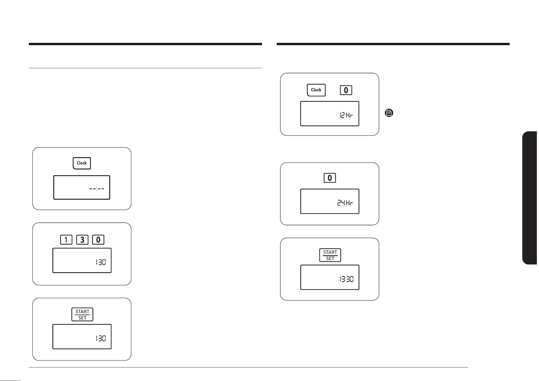
Español 33
Funcionamiento del horno
Cómo efectuar el cambio para ver ciclos de 12 horas o de 24 horas
1. Mantenga presionadas las teclas Clock
(Reloj) y 0 durante 3 segundos.
La pantalla mostrará el modo en uso
(por ej.: 12 horas).
Nota
Si se presiona una tecla antes que la otra,
aparecerá -- -- en la pantalla.
Presione la tecla OFF/CLEAR (APAGAR/
BORRAR) y comience de nuevo.
2. Presione la tecla 0 para cambiar el
ajuste de la pantalla entre 12 horas y
24 horas.
12 h o 24 h aparecerá en la pantalla
dependiendo de su selección.
3. Presione la tecla START/SET (INICIO/
CONFIGURAR) para cambiar el modo de
visualización del reloj.
Ajuste del reloj
El reloj debe ajustarse para mostrar la hora correcta para permitir el buen
funcionamiento de las opciones de temporizador del horno. El reloj se puede
ajustar para mostrar una pantalla de 12 o 24 horas.
El ajuste predeterminado es el de 12 horas.
La hora del día no se puede cambiar durante una cocción programada, un inicio
retardado, la auto-limpieza o la operación de la función Shabat.
Cómo ajustar el reloj
1. Presione la tecla Clock (Reloj).
2. Ingrese la hora actual en horas y
minutos usando las teclas de números
(por ej.: 1, 3, 0).
La pantalla mostrará la hora del día y el
indicador Start (Inicio) parpadeará.
3. Presione la tecla START/SET (INICIO/
CONFIGURAR) para congurar y poner
en funcionamiento el reloj.
La pantalla mostrará la hora del día y el
indicador Start (Inicio) se apagará.
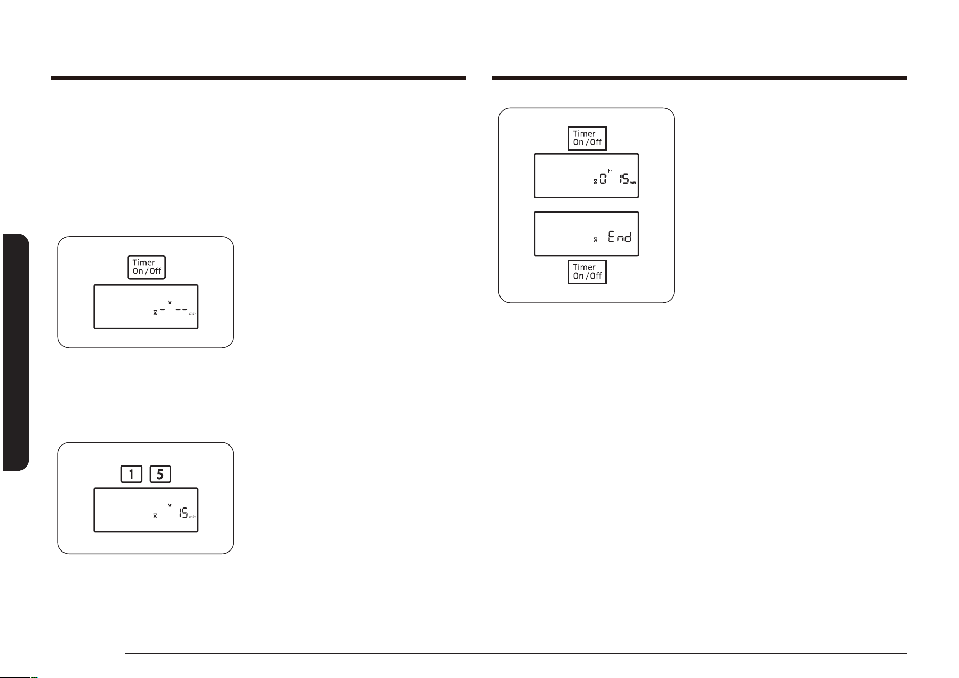
34 Español
Funcionamiento del horno
Funcionamiento del horno
3. Presione la tecla Timer On/Off (Activar/
Desactivar temporizador) para iniciar el
temporizador.
La pantalla mostrará el tiempo restante.
Cuando haya transcurrido el tiempo
jado, el horno emitirá un sonido agudo
y en la pantalla se verá End (Fin) hasta
que usted presione la tecla Timer On/Off
(Activar/Desactivar temporizador). Una
vez que se presione la tecla, la pantalla
volverá a mostrar la hora del día.
El temporizador se puede desactivar
en cualquier momento presionando la
tecla Timer On/Off (Activar/Desactivar
temporizador).
Activación/desactivación del temporizador
El temporizador cuenta regresivamente el tiempo restante y emite señales sonoras
cuando el tiempo programado ha llegado a su n. No inicia ni detiene las funciones
de cocción. El temporizador de cocina puede utilizarse al mismo tiempo que
cualquier otra función de la estufa, y programarlo en cualquier cantidad de tiempo
entre 1 minuto y 9 horas y 99 minutos.
Cómo programar el temporizador
1. Presione la tecla Timer On/Off (Activar/
Desactivar temporizador) una vez para
seleccionar horas y minutos y dos veces
para segundos. Presione la tecla tres
veces para apagar el temporizador de
cocina o para cancelarlo antes de que
comience a funcionar.
La pantalla mostrará
Timer (Temporizador) y -
hr
--
min
parpadeará en la pantalla. (Los
caracteres de hr y min no se
muestran en los modelo NX58*560***,
NX58*751***.)
2. Presione las teclas numéricas para
ingresar la cantidad de tiempo que
desea en minutos, en horas y minutos o
en segundos (por ejemplo, 1, 5).
El tiempo ingresado aparecerá en la
pantalla.
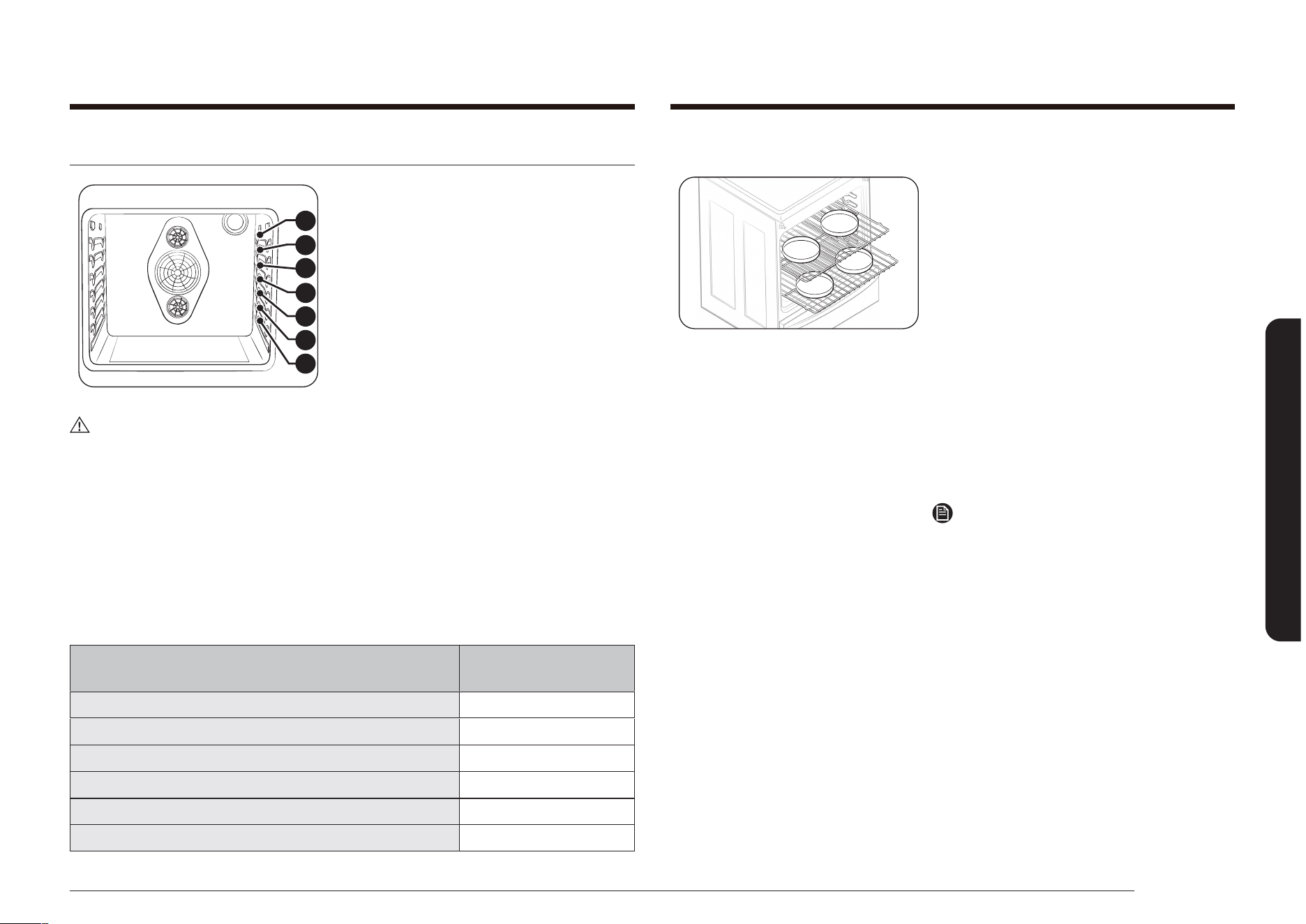
Español 35
Funcionamiento del horno
Posicionamiento de las parrillas del horno.
5
6
7
4
3
2
1
Las parrillas del horno son desmontables y
pueden colocarse en cualquiera de las siete
posiciones de las parrillas en el horno. Cada
parrilla del horno tiene un tope incorporado
para evitar que se retire por completo
en forma accidental. El posicionamiento
adecuado de las parrillas del horno
ofrecerán los mejores resultados de cocción.
El diagrama a la derecha muestra las
posiciones de las parrillas.
PRECAUCIÓN
• No cubra una parrilla del horno con papel de aluminio. Esto alterará la
circulación del calor y creará problemas en el proceso de horneado.
• No coloque papel de aluminio sobre la parte inferior del horno. Puede dañar la
supercie.
• Coloque las parrillas en la distribución deseada solamente cuando el horno se
encuentre frío.
• Cuando coloque una parrilla en la posición superior (posición 7), asegúrese de
que la parrilla se apoye en forma estable en el tope incorporado.
Posiciones de las parrillas en el horno
TIPO DE ALIMENTO
POSICIÓN DE LA
PARRILLA
Hamburguesas y bistec 6 o 7
Tostadas 5 o 6
Panecillos, mufns, brownies, galletas 4
Panqués o pasteles en molde savarin 3
Pastel de ángel, pasteles 2
Carnes asadas (pequeñas o grandes), jamón, pavos 1 o 2
Cómo hornear pasteles en capas
• Centrar las charolas en el horno
producirá mejores resultados de cocción.
• Cuando hornee múltiples alimentos,
asegúrese de dejar un espacio de 1 a
1.5” (2.5 a 3.8 cm) alrededor de cada
alimento.
• Cuando hornee en varias parrillas,
coloque las parrillas en las posiciones
2 y 5.
• Cuando hornee por convección en varias
parrillas, coloque las parrillas en las
posiciones 2 y 5.
• Coloque dos recipientes en la parte
trasera de la parrilla superior y los otros
dos recipientes en la parte delantera de
la parrilla inferior.
Nota
La ubicación adecuada de los alimentos en
el horno le ayudará a lograr los mejores
resultados de cocción.

36 Español
Funcionamiento del horno
Funcionamiento del horno
Uso de la parrilla deslizante (solo NX58*565***)
La parrilla deslizante totalmente extensible facilita la preparación de alimentos,
especialmente cuando se preparan platos más pesados. La parrilla deslizante tiene
2 carriles que permiten extenderla fuera del horno y facilitar así el acceso y la
retirada de los alimentos.
Instalación de la parrilla deslizante
Guías
de la
parrilla
• Con la parrilla deslizante en la posición
“cerrada” y el horno apagado, inserte
cuidadosamente la parrilla entre las
guías hasta que llegue a la parte
posterior.
• Al utilizar la parrilla deslizante en el
horno, asegúrese de deslizarla hacia
adentro y hacia afuera únicamente con
la manija. Si sujeta el marco al utilizar
la parrilla, puede retirar toda la parrilla
deslizante fuera del horno.
Retiro de la parrilla deslizante
• Con la parrilla deslizante en la posición
“cerrada” y el horno apagado y frío,
sujete la parrilla y el marco y jale ambos
hacia usted para retirarlos.
Para retirar una parrilla del horno:
1. Jale la parrilla directamente hacia
afuera hasta que se trabe.
2. Levante la parte delantera de la parrilla
del horno y jálela para retirarla del
horno.
Para volver a colocar una parrilla en el horno:
1. Coloque el borde trasero de la parrilla
en los soportes de parrilla deseados.
2. Levante la parte delantera de la parrilla
y deslícela hacia el horno.
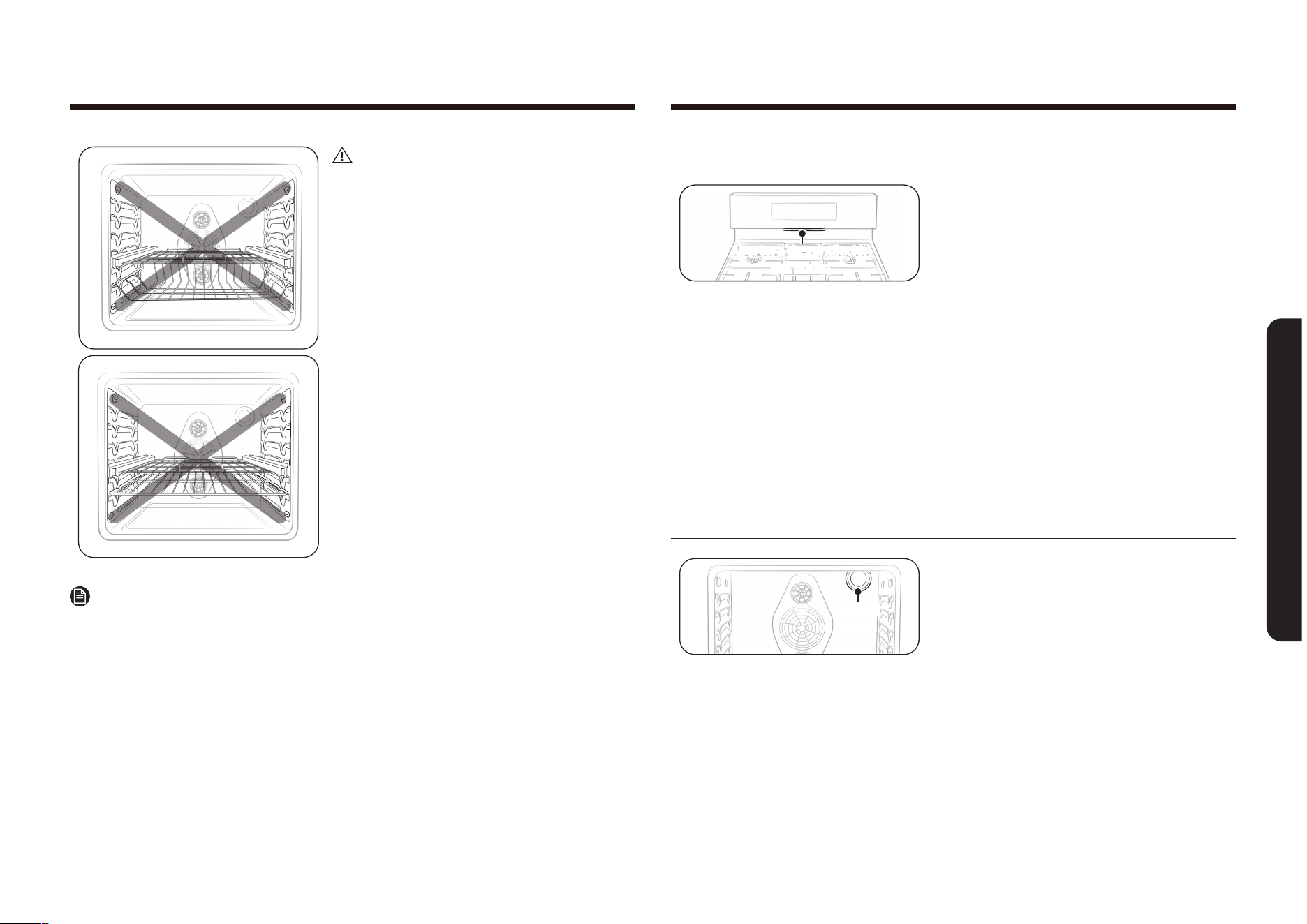
Español 37
Funcionamiento del horno
Abertura de ventilación del horno
Abertura de ventilación
del horno
La abertura de ventilación del horno está
ubicada debajo del panel de control del
horno. No bloquee ni coloque elementos
delante de la abertura de ventilación del
horno La adecuada circulación de aire
evita los problemas de combustión del
quemador del horno y asegura los buenos
resultados de cocción. Dado que la abertura
de ventilación y el área que la rodea
pueden calentarse, tenga cuidado cuando
coloque elementos cerca de la abertura
de ventilación del horno. El vapor caliente
podría calentar o derretir elementos
colocados delante de la abertura de
ventilación del horno.
Luz del horno
Luz del
horno
El horno tiene una luz que está ubicada en
la parte trasera de la pared del horno en
el ángulo trasero superior derecho. La luz
puede encenderse o apagarse tocando la
tecla Luz del horno en el panel de control
del horno. La luz del horno le permite
comprobar el progreso de la cocción sin
abrir la puerta del horno. Siempre use una
bombilla para electrodomésticos de
40 watts cuando reemplace la luz del horno.
Consulte la página 67 para obtener
instrucciones sobre cómo cambiar la
bombilla.
PRECAUCIÓN
No instale la parrilla deslizante
directamente arriba de la parrilla plana y de
la parrilla ahuecada.
No podrá instalarla correctamente y la
parrilla podría caerse.
Nota
Puede instalar la parrilla deslizante en cualquier posición excepto en la más alta
(nivel 7) y la más baja (nivel 1) del horno.
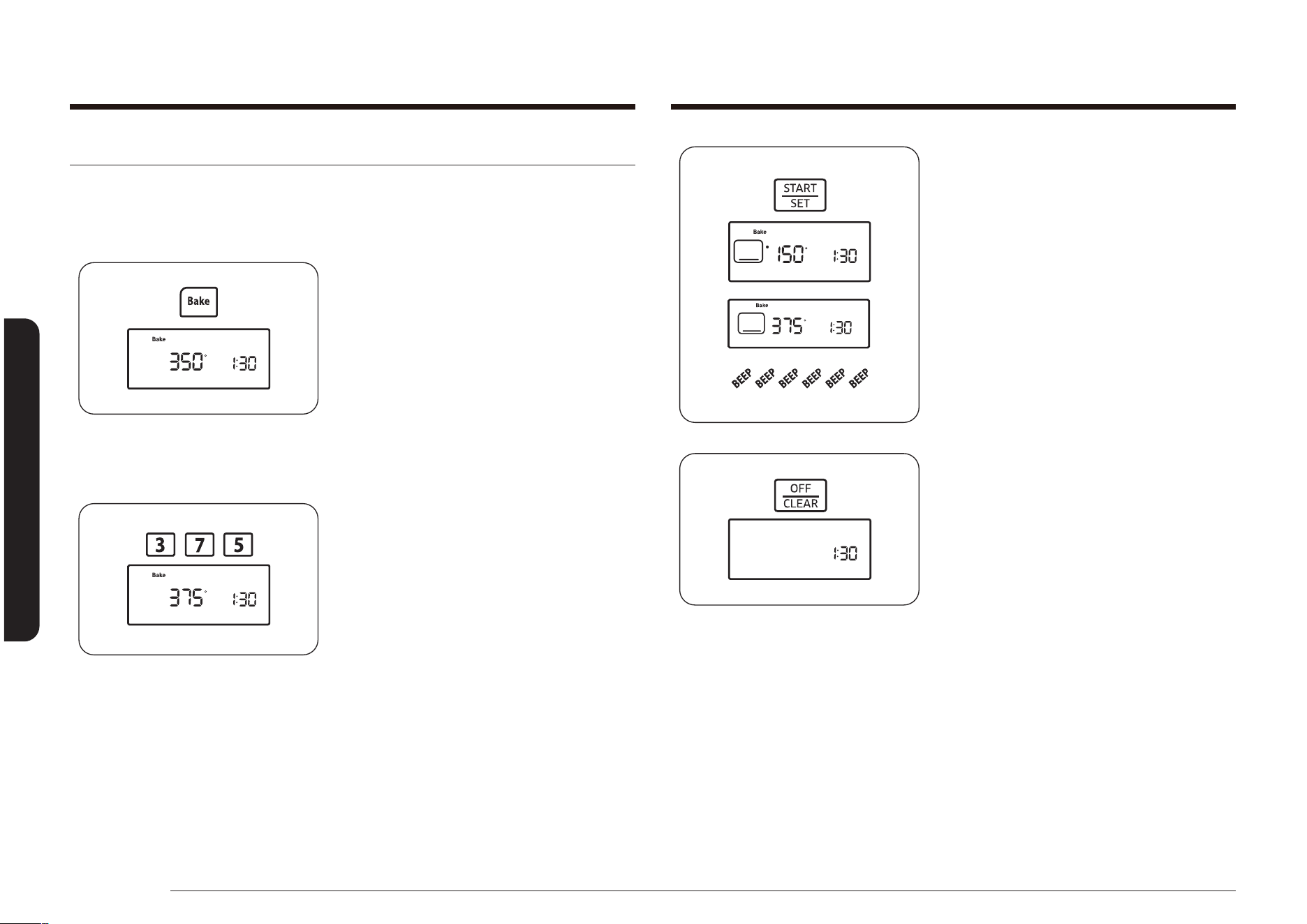
38 Español
Funcionamiento del horno
Funcionamiento del horno
4. Presione la tecla START/SET (INICIO/
CONFIGURAR).
El horno se iniciará automáticamente y
comenzará a precalentarse. La pantalla
mostrará un “•” que parpadea, junto
con 150°, Bake (Hornear) y el icono
del elemento de horneado hasta que
el horno alcance los 150°. Luego, la
pantalla solo mostrará la temperatura
real del horno.
Cuando el horno alcance la temperatura
de horneado deseada, emitirá una señal
sonora 6 veces.
5. Coloque la comida en el horno y cierre
la puerta. El precalentamiento es
muy importante para obtener buenos
resultados en el horneado.
6. Cuando nalice el horneado, retire los
elementos, cierre la puerta del horno y
presione la tecla OFF/CLEAR (APAGAR/
BORRAR).
El horno se apagará y la pantalla
mostrará la hora del día.
Para cambiar una temperatura de horneado programada, presione la tecla
Bake (Hornear), ingrese la nueva temperatura de horneado y, luego, presione la
tecla START/SET (INICIO/CONFIGURAR). Si la temperatura del horno es superior al
nuevo ajuste, el horno emitirá una señal sonora 6 veces y luego mostrará el nuevo
ajuste. El horno completará la cocción a la nueva temperatura.
Hornear
La función Hornear le permite programar el horno para hornear a cualquier
temperatura entre 150 °F (66 °C) y 550 °F (288 °C).
Cómo establecer la temperatura del horno
1. Coloque la parrilla del horno en la
posición deseada.
2. Presione la tecla Bake (Hornear). El
horno emitirá una señal sonora cada vez
que se presione la tecla.
La temperatura predeterminada, 350°,
y el indicador Start (Inicio) parpadearán
en la pantalla. Si la temperatura
predeterminada es la temperatura
deseada de cocción, pase directamente
al paso 4.
3. Presione las teclas numéricas para
ingresar la temperatura de cocción
deseada (por ejemplo, 3, 7, 5).
La temperatura de cocción seleccionada
y el indicador Start (Inicio) parpadearán
en la pantalla.
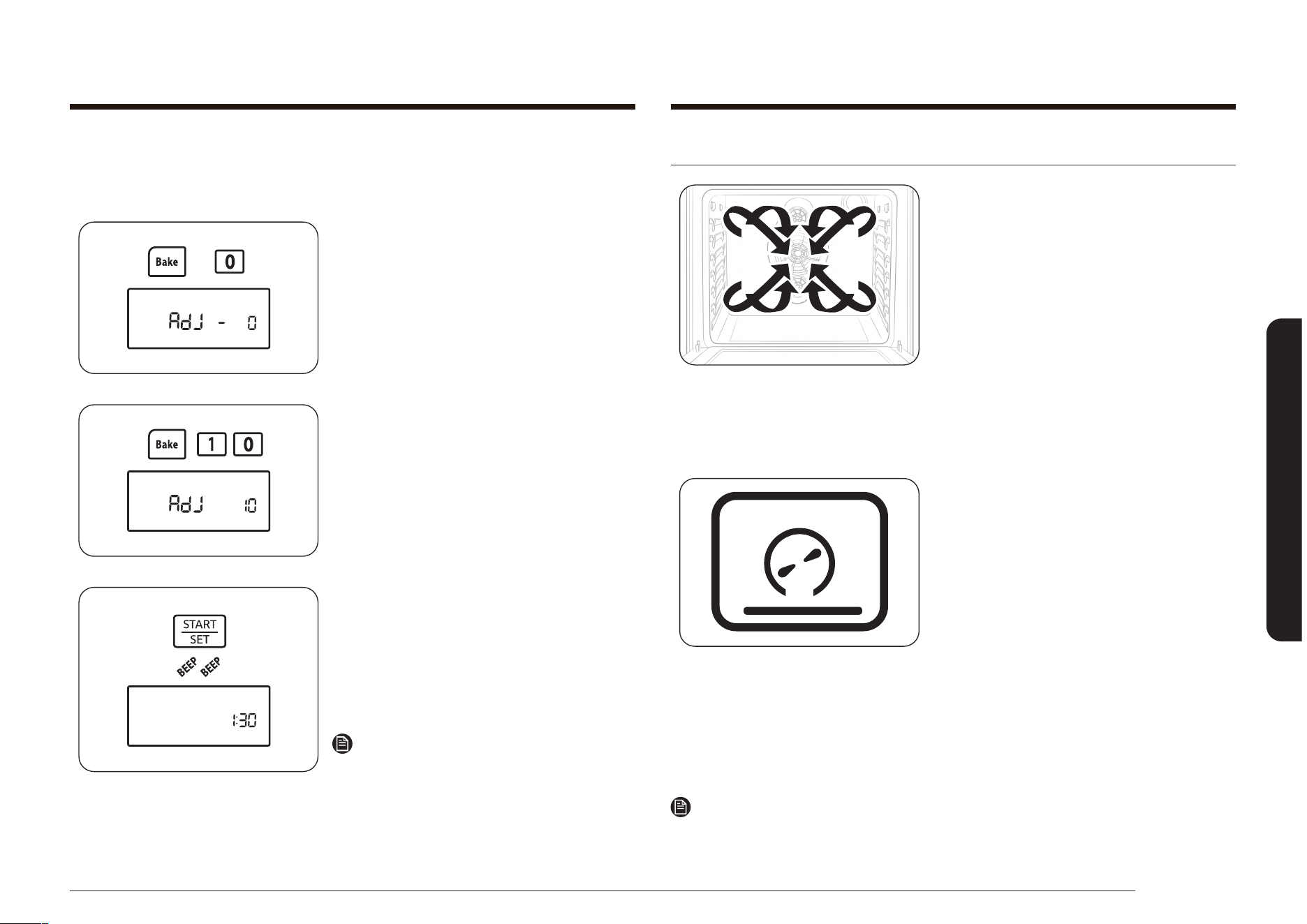
Español 39
Funcionamiento del horno
Hornear por convección y asar al horno por convección
La función Hornear por convección le permite
programar el horno para hornear a cualquier
temperatura entre 150 °F (66 °C) y 550 °F
(288 °C). La función Asar por convección
le permite programar el horno para asar a
cualquier temperatura entre 150 °F (66 °C) y
550 °F (288 °C). El ventilador de convección en
la parte trasera de la cavidad del horno hace
circular el aire caliente en forma pareja por
toda la cavidad del horno. Como resultado, los
alimentos se cocinan y doran en forma pareja en
menos tiempo que con el calor normal.
Hornear por convección
• Ideal para los alimentos que se cocinan en
varias parrillas.
• Bueno para grandes cantidades de alimentos
horneados.
• Ofrece buenos resultados con las galletitas,
galletas, brownies, pastelitos individuales,
mufns, bollos dulces, pastel de ángel y pan.
• Las galletitas tienen mejores resultados de
cocción cuando se cocinan en charolas planas
para galletitas.
• Cuando hornea en una única parrilla, coloque
la parrilla del horno en la posición 3 o 4.
Cuando hornee por convección en varias
parrillas, coloque las parrillas en las
posiciones 2 y 5.
Nota
El horno ajusta automáticamente la temperatura para hornear por convección con la función
de Auto-conversión por convección. Consulte la página 57 para obtener más detalles.
Si sus resultados de cocción no son a lo que usted está acostumbrado, la
temperatura de cocción del horno programada puede ajustarse
±30 °F (±15 °C) del siguiente modo:
1. Mantenga presionadas las teclas Bake
(Hornear) y 0 durante 3 segundos.
La pantalla mostrará AdJ y 0.
2. Presione la tecla Bake (Hornear) para
seleccionar los ajustes de temperatura
+ o –.
3. Presione las teclas numéricas para
ingresar el ajuste de temperatura
deseado (por ejemplo 1, 0).
La pantalla mostrará AdJ y 10.
4. Presione la tecla START/SET (INICIO/
CONFIGURAR).
El horno emitirá una señal sonora dos
veces y la pantalla mostrará la hora
del día. La próxima vez que hornee,
el horno utilizará el nuevo ajuste de
temperatura.
Nota
Este ajuste no afectará las temperaturas
para asar a la plancha ni la de auto-
limpieza.
El ajuste se mantendrá en la memoria
incluso después de un corte de electricidad.
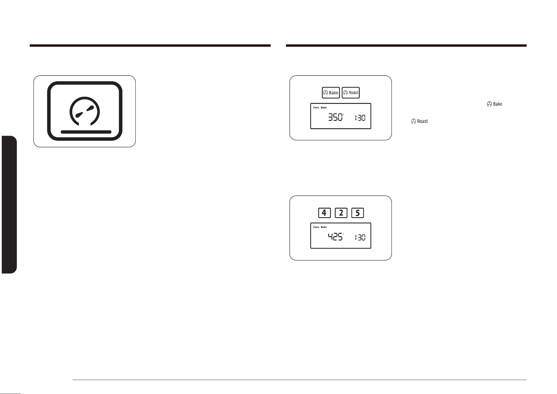
40 Español
Funcionamiento del horno
Funcionamiento del horno
Cómo ajustar el horno para hornear o asar por convección
1. Coloque la parrilla del horno en la
posición deseada.
2. Presione la tecla Convection Bake
(Hornear por convección) ( ) o
Convection Roast (Asar por convección)
( ).
El horno emitirá una señal sonora cada
vez que se presione la tecla.
La temperatura predeterminada,
350°, parpadeará en la pantalla. Si la
temperatura predeterminada es la
temperatura deseada de cocción, pase
directamente al paso 4.
3. Presione las teclas numéricas para
ingresar la temperatura de cocción
deseada (por ejemplo, 4, 2, 5).
La temperatura de cocción seleccionada
parpadeará en la pantalla.
Asar por convección
• Adecuado para cortes de carne tiernos
más grandes, destapados.
• Coloque una asadera y una rejilla
debajo de la carne vacuna o la carne de
ave mientras asa por convección para
obtener mejores resultados. La asadera
retiene los derrames de grasa y la rejilla
evita las salpicaduras de grasa.
Las carnes, incluidas las aves, se doran por todos lados como si hubiesen sido
cocidas en un rosticero (asador giratorio). El aire caliente circulará sobre, debajo y
alrededor de la comida que se está asando. El aire caliente rápidamente sella los
alimentos dejando dentro los jugos y el interior queda jugoso y tierno, mientras
que el exterior adquiere un atractivo color pardo dorado.
Consulte las Guía de asado por convección en la página 41 para conocer los
tiempos y temperaturas de cocción recomendados.
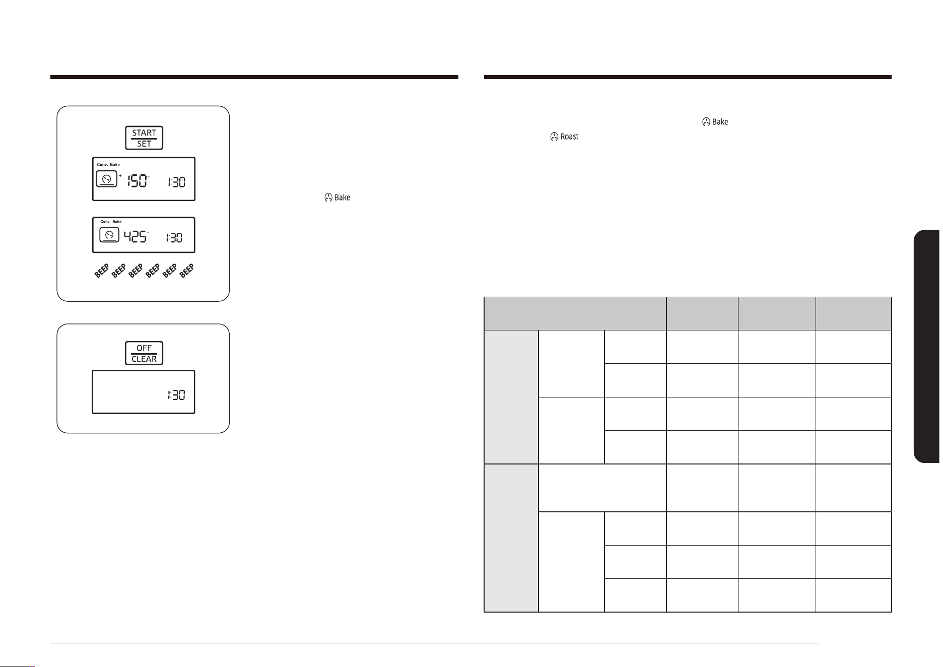
Español 41
Funcionamiento del horno
4. Presione la tecla START/SET (INICIO/
CONFIGURAR).
El horno se iniciará automáticamente y
comenzará a precalentarse. La pantalla
mostrará un “•” que parpadea, junto
con 150°, Conv. Bake (Hornear por
convección) ( ), y los iconos de
elemento de horneado por convección
y ventilador, hasta que el horno llegue
a los 150°. Luego, la pantalla solo
mostrará la temperatura real del horno.
Cuando el horno alcance la temperatura
de horneado o asado deseada, emitirá
una señal sonora 6 veces.
5. Coloque la comida en el horno y cierre
la puerta.
El precalentamiento es muy importante
para obtener buenos resultados en
el horneado. Se debe asar sobre una
asadera y una rejilla.
6. Cuando naliza el horneado o asado,
retire los elementos, cierre la puerta del
horno y presione la tecla OFF/CLEAR
(APAGAR/BORRAR).
El horno se apagará y la pantalla
mostrará la hora del día.
Para cambiar una temperatura de horneado o asado programada, presione la tecla
Convection Bake (Hornear por convección) ( ) o Convection Roast (Asar por
convección) ( ), ingrese la nueva temperatura de cocción y, luego, presione la
tecla START/SET (INICIO/CONFIGURAR).
Si la temperatura del horno es superior al nuevo ajuste, el horno emitirá una señal
sonora 6 veces y luego mostrará el nuevo ajuste. El horno completará la cocción a
la nueva temperatura.
Guía de asado por convección
Los tiempos necesarios para asar al horno dependerán del tamaño, peso, espesor,
temperatura de asado y su gusto en cuanto al grado de cocción.
La siguiente guía se basa en alimentos que comienzan a temperatura del
refrigerador.
Alimento
Minutos por
libra
Temperatura
del horno
Temperatura
interna
Carne de
res
Asado de
costillar
(3 a 5 lb)
Al punto 28–33
350 °F
(177 °C)
160 °F
(71 °C)
Muy
hecho
30–38
350 °F
(177 °C)
170 °F
(77 °C)
Asado de
lomo
(2 a 3 lb)
Al punto 35–45
350 °F
(177 °C)
160 °F
(71 °C)
Muy
hecho
45–55
350 °F
(177 °C)
170 °F
(77 °C)
Carne de
cerdo
Asado
(sin hueso o con hueso)
(3 a 5 lb)
22–28
350 °F
(177 °C)
170 °F
(77 °C)
Chuletas
(grosor de
0.5 a 1”)
2 chuletas 30–40 total
350 °F
(177 °C)
170 °F
(77 °C)
4 chuletas 40–50 total
350 °F
(177 °C)
170 °F
(77 °C)
6 chuletas 45–55 total
350 °F
(177 °C)
170 °F
(77 °C)
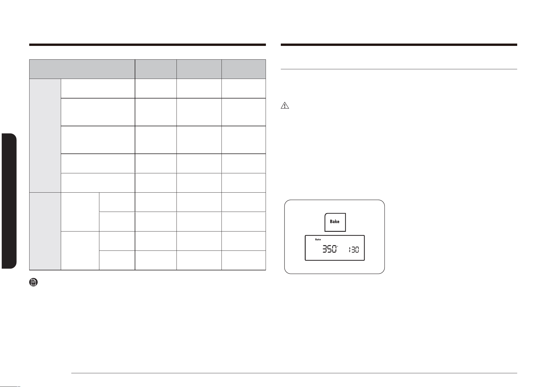
42 Español
Funcionamiento del horno
Funcionamiento del horno
Cocción regida por temporizador
La función Tiempo de cocción le permite programar el horno para cocinar la
comida a una temperatura establecida durante un tiempo determinado. Una vez
completado ese tiempo establecido, el horno se apagará automáticamente.
PRECAUCIÓN
Tenga cuidado cuando use las funciones Tiempo de cocción e Inicio retardado.
Estas funciones son mejor utilizadas para cocinar carnes curadas o congeladas y la
mayor parte de las frutas y vegetales. Los alimentos que pueden echarse a perder
fácilmente como la leche, los huevos, el pescado, las aves y las carnes, deben
enfriarse en un refrigerador antes de colocarse en el horno. Aún enfriados, no
deben permanecer en el horno durante más de una hora antes de que se inicie la
cocción y una vez nalizada la cocción deben retirarse a la brevedad. La ingestión
de alimentos en mal estado puede producir intoxicación alimentaria.
Cómo programar el horno para cocción regida por el temporizador
1. Coloque la parrilla del horno en la
posición deseada. Coloque la comida en
el horno y cierre la puerta.
2. Presione la tecla Bake (Hornear).
La temperatura predeterminada,
350°, parpadeará en la pantalla. Si la
temperatura predeterminada es la
temperatura deseada de cocción, pase
directamente al paso 4.
Alimento
Minutos por
libra
Temperatura
del horno
Temperatura
interna
Ave
Pollo, entero
(2.5 a 3.5 lb)
26–30
375 °F
(191 °C)
180 °F
(82 °C)
Pavo, entero
(sin relleno*)
(10 a 16 lb)
10–16
325 °F
(163 °C)
180 °F
(82 °C)
Pavo, entero
(sin relleno*)
(18 a 24 lb)
8–15
325 °F
(163 °C)
180 °F
(82 °C)
Pechuga de pavo
(4 a 6 lb)
18–23
325 °F
(163 °C)
170 °F
(77 °C)
Gallinita (1 a 1.5 lb) 50–75 total
325 °F
(163 °C)
180 °F
(82 °C)
Cordero
Media pata
(3 a 4 lb)
Al punto 25–30
325 °F
(163 °C)
160 °F
(71 °C)
Muy
hecho
30–35
325 °F
(163 °C)
170 °F
(77 °C)
Pata
entera
(6 a 7 lb)
Al punto 25–30
325 °F
(163 °C)
160 °F
(71 °C)
Muy
hecho
30–35
325 °F
(163 °C)
170 °F
(77 °C)
Nota
* El pavo relleno requiere más tiempo para asarse. La temperatura segura mínima
para rellenar la carne de ave es 165 °F (74 °C).
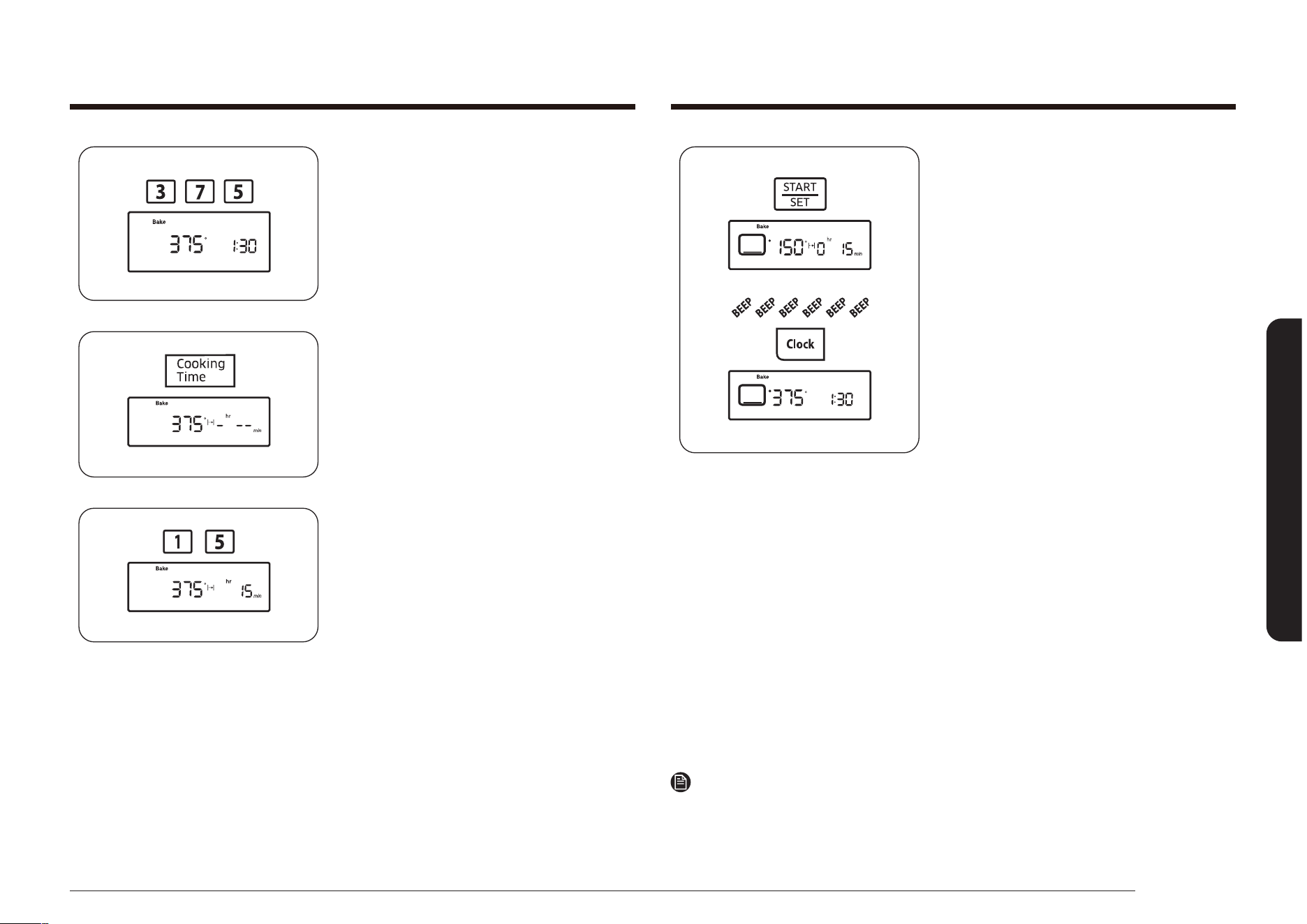
Español 43
Funcionamiento del horno
Presione la tecla START/SET (INICIO/
CONFIGURAR).
El horno se iniciará automáticamente y
comenzará a precalentarse. La pantalla
mostrará un
“•”
que parpadea junto
con la temperatura predeterminada o
seleccionada, Bake (Hornear) y el icono
del elemento de horneado, hasta que el
horno alcance esa temperatura.
Cuando el horno alcanza la temperatura
deseada, emite una señal sonora 6 veces.
El horno comenzará a cocinar durante
la cantidad de tiempo establecida, y se
mostrará el tiempo de cocción restante.
Para congurar la hora del día, mantenga
presionada la tecla Clock (Reloj). Cuando
se suelta la tecla Clock (Reloj), la pantalla
regresa al tiempo de cocción restante. Una
vez transcurrido el tiempo de cocción, el
horno se apagará automáticamente y la
pantalla mostrará la hora del día.
Para cambiar una temperatura de horneado programada, presione la tecla Bake
(Hornear), ingrese la nueva temperatura de horneado y presione la tecla START/
SET (INICIO/CONFIGURAR). Si la temperatura del horno es superior al nuevo ajuste,
el horno emitirá una señal sonora 6 veces y luego mostrará el nuevo ajuste. El
horno completará la cocción a la nueva temperatura.
Para cambiar un tiempo de cocción programado, presione la tecla Cooking Time
(Tiempo de cocción), ingrese el nuevo tiempo de cocción y, luego, presione la tecla
START/SET (INICIO/CONFIGURAR). El horno seguirá cocinando durante el nuevo
tiempo congurado restante.
Nota
Coloque los alimentos en el horno después de precalentarlo, si así lo requiere la
receta. El precalentamiento es importante para obtener buenos resultados en el
horneado. Cuando el horno haya alcanzado la temperatura de cocción deseada,
emitirá una señal sonora 6 veces.
3. Presione las teclas numéricas para
ingresar la temperatura de cocción
deseada (por ejemplo, 3, 7, 5).
La temperatura de cocción seleccionada
parpadeará en la pantalla.
4. Presione la tecla Cooking Time (Tiempo
de cocción).
La pantalla mostrará -
hr
--
min
.
(Los caracteres de hr, min no se
muestran en los modelo NX58*560***,
NX58*751***)
5. Presione las teclas numéricas para
ingresar el tiempo de cocción deseado.
La pantalla mostrará el tiempo
seleccionado y el indicador Start (Inicio)
parpadeará. Puede congurar el tiempo
en cualquier período entre 1 minuto y 9
horas y 99 minutos.
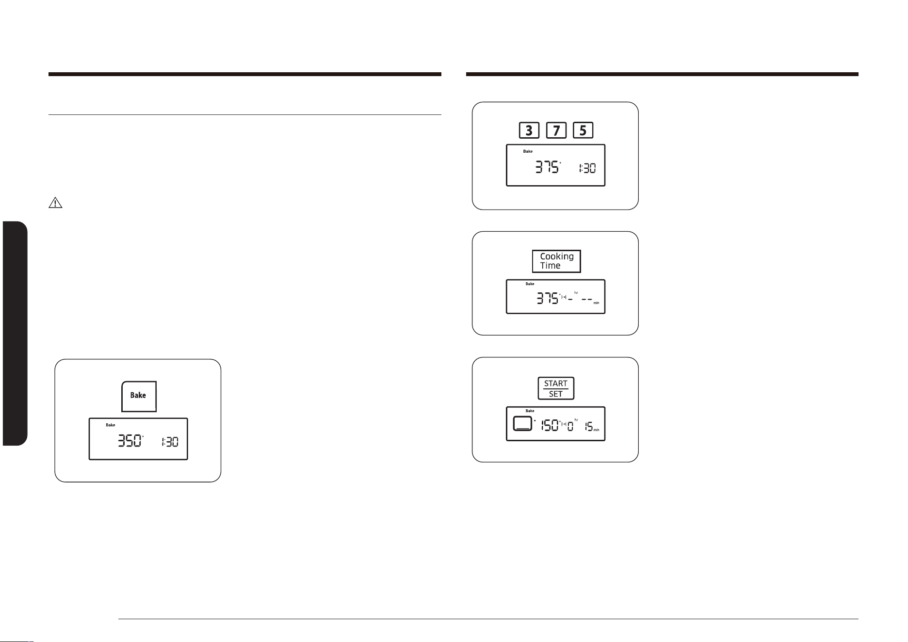
44 Español
Funcionamiento del horno
Funcionamiento del horno
3. Presione las teclas numéricas para
ingresar la temperatura de cocción
deseada (por ejemplo, 3, 7, 5).
La temperatura de cocción seleccionada
y el indicador Start (Inicio) parpadearán
en la pantalla.
4. Presione la tecla Cooking Time (Tiempo
de cocción).
La pantalla mostrará la temperatura de
cocción seleccionada, Bake (Hornear) y
-
hr
--
min
.
(Los caracteres HR, min no se
muestran en los modelo NX58*560***,
NX58*751***)
5. Presione las teclas numéricas para
ingresar el tiempo de cocción deseado.
La pantalla mostrará el tiempo de
cocción seleccionado y el indicador Start
(Inicio) parpadeará. Puede congurar el
tiempo en cualquier cantidad de tiempo
entre 1 minuto y 9 horas y 99 minutos.
Cocción temporizada diferida
La función de inicio retardado le permite usar el temporizador de cocina para
iniciar y detener automáticamente otro programa de cocción (hornear, hornear por
convección o asar por convección). El Inicio retardado puede congurarse antes de
otras funciones de cocción hasta por 12 horas. El reloj debe ajustarse para mostrar
la hora correcta para permitir el buen funcionamiento del inicio retardado.
PRECAUCIÓN
Tenga cuidado cuando use las funciones Tiempo de cocción e Inicio retardado.
Estas funciones son mejor utilizadas para cocinar carnes curadas o congeladas y la
mayor parte de las frutas y vegetales. Los alimentos que pueden echarse a perder
fácilmente como la leche, los huevos, el pescado, las aves y las carnes, deben
enfriarse en un refrigerador antes de colocarse en el horno. Aún enfriados, no
deben permanecer en el horno durante más de una hora antes de que se inicie la
cocción y una vez nalizada la cocción deben retirarse a la brevedad. La ingestión
de alimentos en mal estado puede producir intoxicación alimentaria.
Cómo programar el horno para cocción temporizada diferida
1. Coloque la parrilla del horno en la
posición deseada. Coloque la comida en
el horno y cierre la puerta.
2. Presione la tecla para el funcionamiento
en la cocción deseada,
por ej.: Bake (Hornear).
La temperatura predeterminada, 350°,
y el indicador Start (Inicio) parpadearán
en la pantalla. Si la temperatura
predeterminada es la temperatura
deseada de cocción, pase directamente
al paso 4.
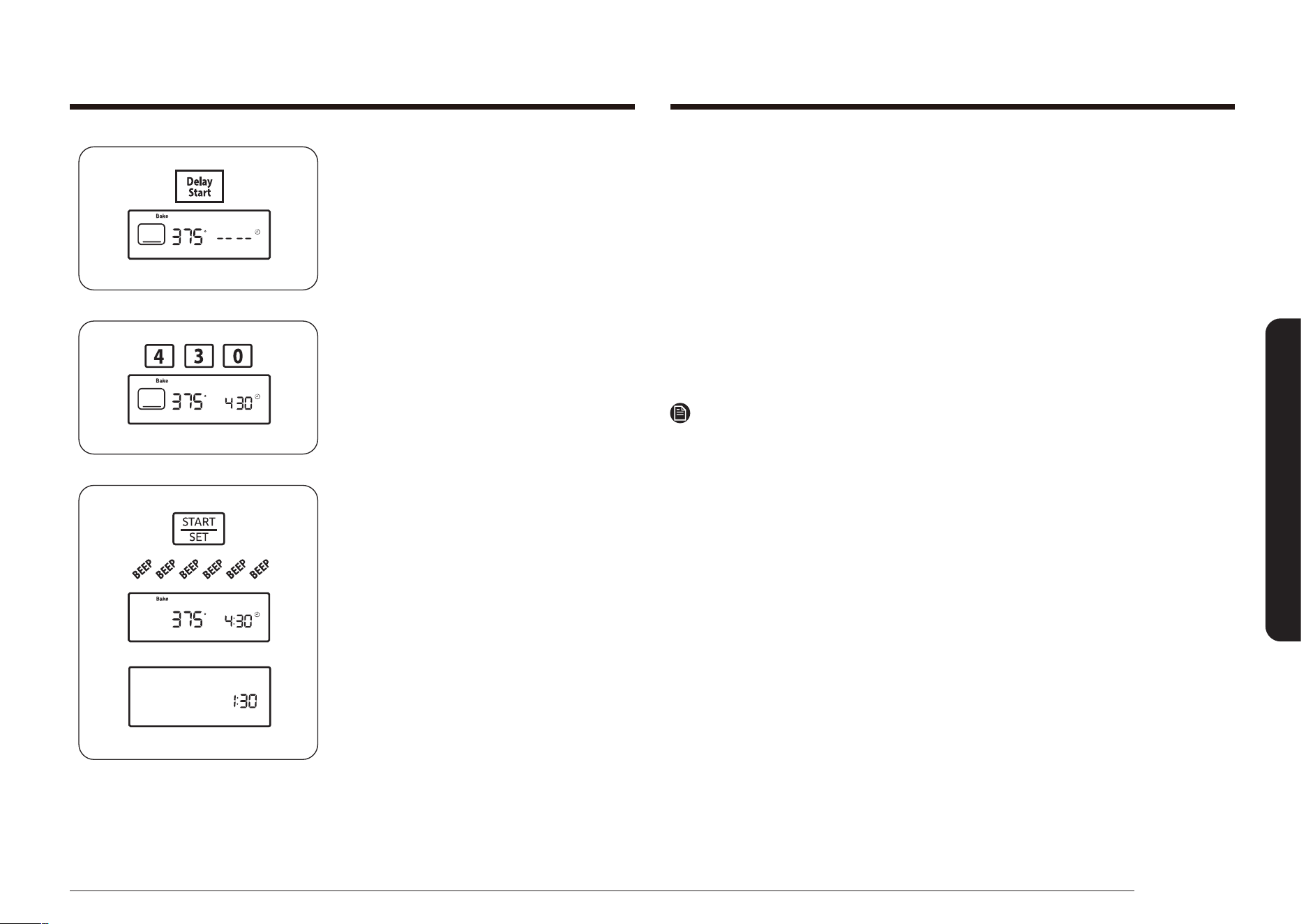
Español 45
Funcionamiento del horno
Para cambiar un tiempo de inicio programado, presione la tecla Delay Start (Inicio
retardado), ingrese el nuevo tiempo de inicio y, luego, presione la tecla START/SET
(INICIO/CONFIGURAR). El horno comenzará la cocción a la nueva hora de inicio.
Para cambiar una temperatura de horneado programada, presione la tecla Bake
(Hornear), ingrese la nueva temperatura de horneado y, luego, presione la tecla
START/SET (INICIO/CONFIGURAR). Si la temperatura del horno es superior al nuevo
ajuste, el horno emitirá una señal sonora 6 veces y luego mostrará el nuevo ajuste.
El horno completará la cocción a la nueva temperatura.
Para cambiar un tiempo de cocción programado, presione la tecla Cooking Time
(Tiempo de cocción), ingrese el nuevo tiempo de cocción y, luego, presione la tecla
START/SET (INICIO/CONFIGURAR). El horno seguirá cocinando durante el nuevo
tiempo congurado restante.
Nota
Coloque los alimentos en el horno después de precalentarlo, si así lo requiere la
receta.
El precalentamiento es importante para obtener buenos resultados en el horneado.
Cuando el horno haya alcanzado la temperatura de cocción deseada, emitirá una
señal sonora 6 veces.
6. Presione la tecla Delay Start (Inicio
retardado).
La pantalla mostrará Delay (Retardo) y
-- -- parpadeará.
7. Presione las teclas numéricas para
ingresar la hora a la que desea que el
horno se encienda (por ejemplo, 4, 3, 0).
El indicador Start (Inicio) parpadeará
debajo de Delay (Retardo) y el tiempo
de inicio seleccionado.
8. Presione la tecla START/SET (INICIO/
CONFIGURAR).
El horno se encenderá automáticamente
y emitirá un sonido cuando se llegue a
la hora de inicio.
El horno se iniciará automáticamente y
comenzará a precalentarse. Cuando el
horno alcanza la temperatura de cocción
deseada, emite una señal sonora 6
veces.
La pantalla mostrará una cuenta
regresiva del tiempo de cocción.
Una vez transcurrido el tiempo
de cocción, el horno se apagará
automáticamente y la pantalla mostrará
la hora del día.

46 Español
Funcionamiento del horno
Funcionamiento del horno
3. Presione la tecla START/SET (INICIO/
CONFIGURAR).
El horno encenderá automáticamente
el quemador del horno superior y
comenzará la cocción.
La pantalla mostrará el ajuste de asado
a la parrilla seleccionado (Alto o Bajo), el
icono del elemento de asado a la parrilla
y Broil (Asar a la parrilla).
Ase a la parrilla sobre un lado hasta que
los alimentos queden dorados; luego
deles vuelta y cocine el otro lado.
Cuando nalice la cocción, presione la
tecla OFF/CLEAR (APAGAR/BORRAR)
para apagar el horno o para cancelar
el asado a la parrilla en cualquier
momento. La pantalla mostrará la hora
del día.
Para cambiar un ajuste de asado a la parrilla programado, presione la tecla Broil
(Asar a la parrilla) para cambiar entre Hi (Alto) y Lo (Bajo). Presione la tecla START/
SET (INICIO/CONFIGURAR) para nalizar la cocción con el nuevo ajuste.
Asar a la parrilla
La función de Asar a la parrilla le permite cocinar y dorar alimentos usando
solo una fuente de calor superior. La puerta del horno debe permanecer cerrada
durante el asado a la parrilla. La carne o el pescado deben colocarse siempre sobre
una rejilla y una asadera.
PRECAUCIÓN
Si se produce fuego cuando se asa a la parrilla, deje la puerta del horno cerrada y
apague el horno. Si el fuego continúa, arroje bicarbonato de sodio sobre las llamas
o utilice un extintor de espuma. No eche agua ni harina sobre el fuego. La harina
puede explotar y el agua hacer que la grasa encendida se extienda. Ambos pueden
causar lesiones físicas y daños materiales.
Cómo ajustar el horno para asar a la parrilla
1. Coloque la comida sobre una asadera
con una rejilla incorporada. Coloque la
comida y la asadera sobre la parrilla
superior, ubicada según se recomienda
en la Guía para asar a la parrilla en la
página 47. Cierre la puerta del horno.
2. Presione la tecla Broil (Asar a la parrilla)
una vez para Hi (Alto) y dos veces para
Lo (Bajo). El horno emitirá una señal
sonora cada vez que se presione la tecla.
El indicador Start (Inicio) parpadeará
a la derecha de Hi (Alto) o Lo (Bajo) y
Broil (Asar a la parrilla) en la pantalla.
Use Lo (Bajo) para cocinar comidas tales
como aves o cortes de carne gruesos sin
tostarlos en exceso.
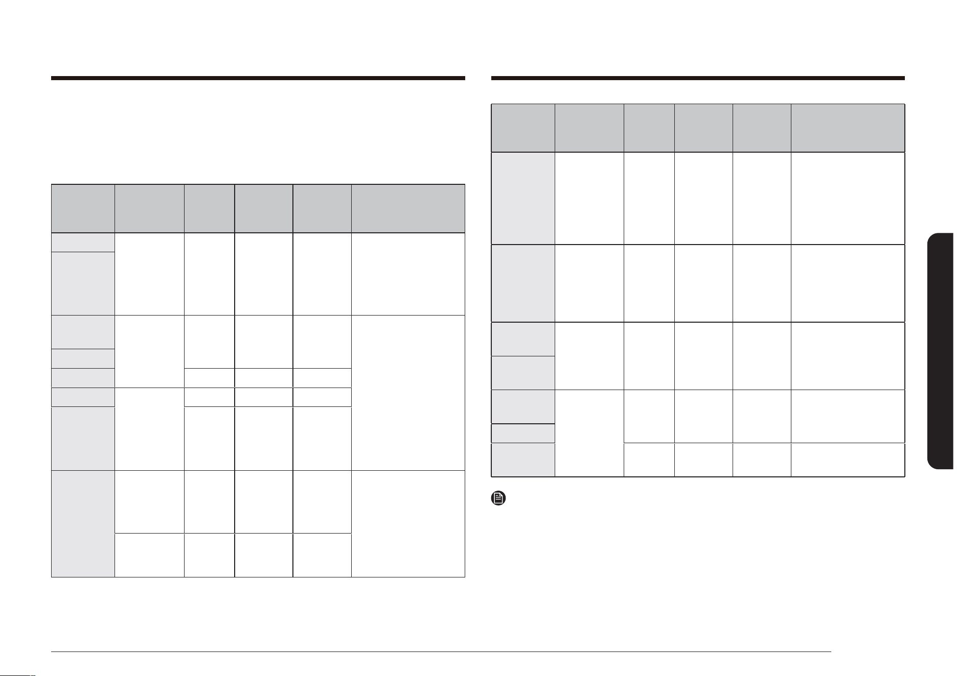
Español 47
Funcionamiento del horno
Alimento
Cantidad y/
o grosor
Posición
de la
parrilla*
Tiempo
primer lado
(min.)
Tiempo
segundo
lado (min.)
Comentarios
Filetes de
pescado
0.25 a 0.5”
de espesor
6 6-10 3-4
Manejar y dar vuelta con
mucho cuidado.
Cepillar con una mezcla
de mantequilla y limón
previamente y durante la
cocción, si así lo desea.
Lonchas de
jamón
(precocido)
0.5” espesor 6 7-10 5-6
Aumente el tiempo de
cocción de 5 a 10 minutes
por lado para lonchas de
1.5 pulgadas de grosor o
jamón de curado casero.
Chuletas de
cerdo
Muy hecho
2 (0.5” de
espesor)
6 8-11 4-6
Efectuar cortes en la
grasa.
Chuletas de
cordero
Al punto
2 (1” espesor)
de alrededor
de 10 a 12 oz
6 8-12 5-8 -
Muy hecho 6 10-16 7-11
Efectuar cortes en la
grasa.
Nota
* Consulte la ilustración en la página 35 para ver una descripción de las posiciones
de la parrilla.
Guía para asar a la parrilla
Los tiempos necesarios para asar a la parrilla dependerán del tamaño, peso,
espesor, temperatura de asado y su gusto en cuanto al grado de cocción. La
siguiente guía se basa en carnes o pescado que comienzan a temperatura del
refrigerador.
Alimento
Cantidad y/
o grosor
Posición
de la
parrilla*
Tiempo
primer lado
(min.)
Tiempo
segundo
lado (min.)
Comentarios
Carne molida
Muy hecho
1 lb (4
hamburguesas)
0.5 a 0.75”
espesor
6 o 7 7-10 5-7
Uniformemente
espaciados Se pueden
asar hasta 8 croquetas o
hamburguesas a la vez
Bistecs
(carne de res)
Mediano
1” espesor,
1 a 1.5 lbs
6 10-12 5-7 Los bistecs de menos de
una pulgada de espesor
se cocinan completamente
antes de dorarse.
Se recomienda cocer en
sartén.
Efectuar cortes en la
grasa.
Muy hecho 6 12-14 6-8
Al punto
1.5” espesor,
2 a 2.5 lbs
6 15-18 14-17
Muy hecho 6 18-22 17-19
Pollo
1 entero
trozado 2 a 2.5
libras,
abrir a lo largo
4 30-35 15-20
Asar primero con la piel
hacia abajo.
Abrir para extender.
Cepillar con mantequilla
derretida antes de asar y
en la mitad del asado a la
parrilla.
2 pechugas 5 15-20 7-12
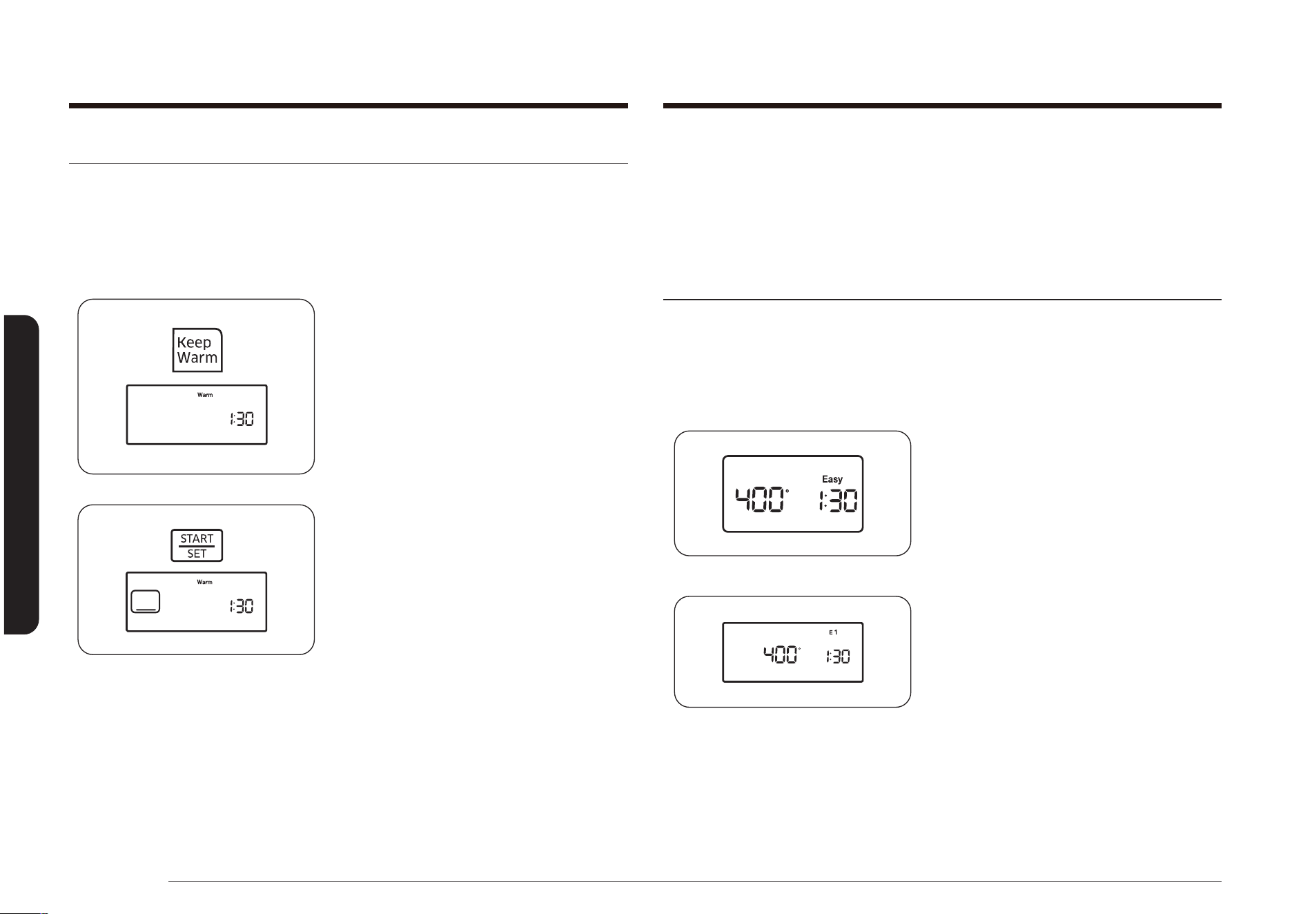
48 Español
Funcionamiento del horno
Funcionamiento del horno
Para programar Mantener caliente después de una función de cocción
programada, presione la tecla Keep Warm (Mantener caliente) después de
programar la función de cocción programada. Cuando naliza la Cocción por
tiempo, el horno emitirá una señal sonora 6 veces y bajará la temperatura del
horno para el ajuste Mantener caliente. El horno mantendrá la temperatura hasta
que se cancele Mantener caliente.
Cómo utilizar la función de cocción fácil
Pizza
La función de pizza está diseñada para producir una base crujiente y tostada y a la
vez mantener los ingredientes húmedos.
Cómo congurar la función Pizza
NX58*560***, NX58*751***
NX58*565***
1. Presione la tecla Pizza.
Mantener caliente
La función Mantener caliente le permite mantener comidas cocinadas calientes a
una baja temperatura de horneado. Esta función mantiene los alimentos calientes
a una temperatura apta para servir por hasta 3 horas después de nalizada la
cocción. Después de 3 horas, la función apaga el horno automáticamente.
Cómo utilizar la función de mantener temperatura
1. Coloque la parrilla del horno en la
posición deseada. Coloque la comida en
el horno y cierre la puerta del horno.
2. Presione la tecla Keep Warm (Mantener
caliente).
El indicador Start (Inicio) parpadeará
debajo de la hora del día y aparecerá
Warm (Calentar) en la pantalla.
3. Presione la tecla START/SET (INICIO/
CONFIGURAR).
El horno se encenderá y comenzará
automáticamente el precalentamiento
hasta la temperatura de Mantener
caliente (aprox. 170 °F [77 °C]). La
pantalla mostrará el icono del elemento
del horno, Warm (Calentar) y la hora del
día.
Para cancelar Keep Warm (Mantener
caliente) y apagar el horno, presione la
tecla OFF/CLEAR (APAGAR/BORRAR). La
pantalla mostrará la hora del día.

Español 49
Funcionamiento del horno
Cocción lenta
Se puede utilizar la función de cocción lenta para cocinar alimentos más
lentamente a temperaturas del horno más bajas. Los tiempos de cocción
prolongados permiten una mejor distribución de sabores en muchas recetas. Esta
función es ideal para asar carne, cerdo y aves. Cocinar lentamente la carne puede
provocar que la parte exterior se oscurezca pero no se queme. Esto es normal.
Cómo congurar la función cocción lenta
NX58*560***, NX58*751***
NX58*565***
1. Presione la tecla Slow Cook (Cocción
lenta) una vez para HI (Alta) o dos veces
para LO (Baja).
NX58*560***, NX58*751***
NX58*565***
2. Presione la tecla SET/START
(CONFIGURAR/INICIO) para comenzar
con la cocción de la pizza.
Nota
• Use solo 1 parrilla y coloque la parrilla en la posición 3 o 4 para obtener los
mejores resultados al usar la función pizza.
• La temperatura predeterminada es 400 °F. Puede ajustar la temperatura del
horno para que se adapte a sus necesidades.
• Siga las instrucciones del paquete para los tiempos de precalentado y
horneado.
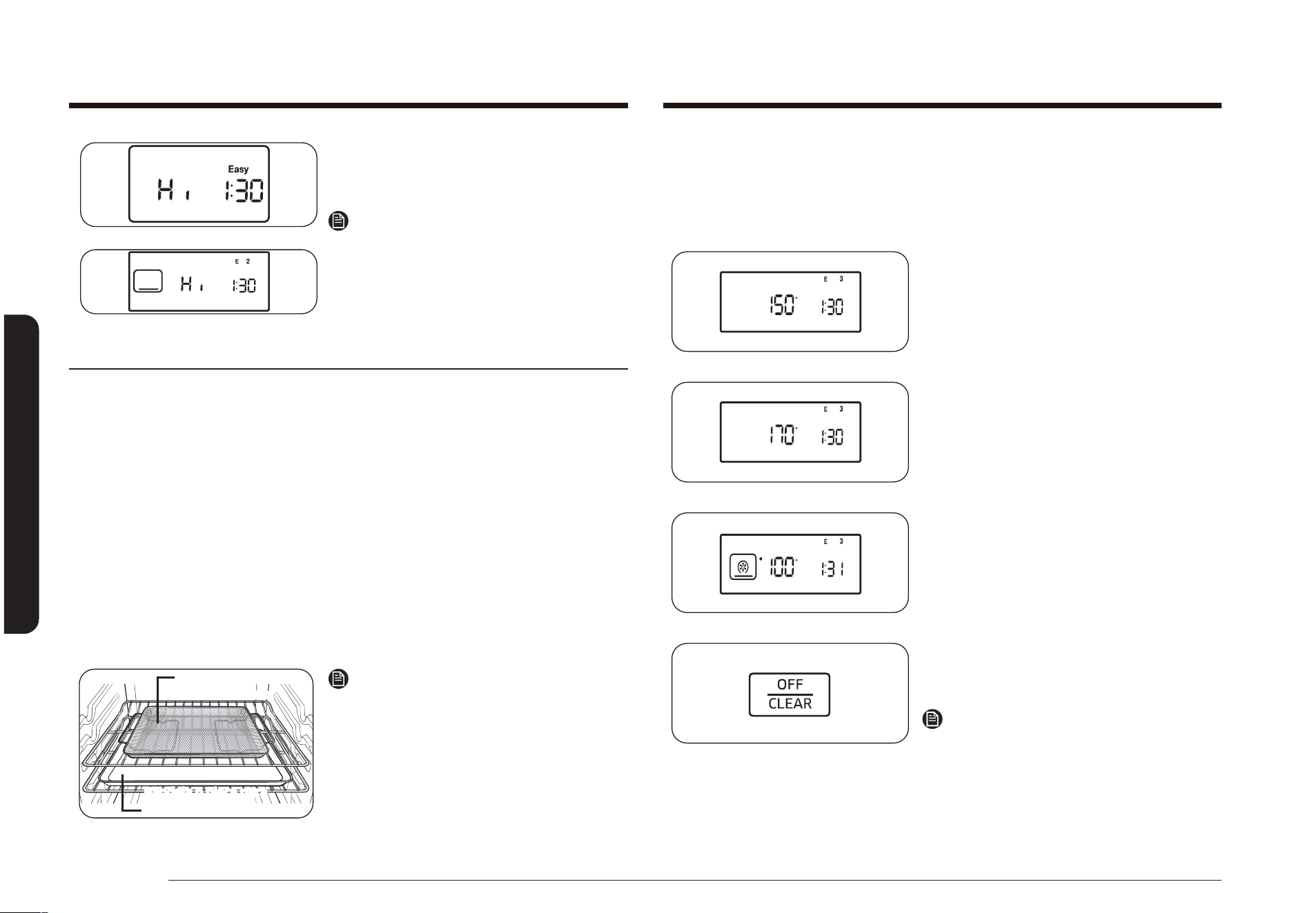
50 Español
Funcionamiento del horno
Funcionamiento del horno
Deshidratar
Esta función está diseñada para secar alimentos o eliminar la humedad de los
alimentos mediante la circulación de calor.
Cómo congurar la función deshidratar
1. Presione la tecla Dehydrate
(Deshidratar).
2. Presione las teclas numéricas para
establecer la temperatura deseada.
(congurar entre 100 °F y 175 °F)
3. Presione la tecla START/SET (INICIO/
CONFIGURAR) para iniciar el modo de
deshidratar.
4. Cuando el alimento esté deshidratado,
presione la tecla OFF/CLEAR (APAGAR/
BORRAR).
Nota
• No precaliente el horno para esta
función.
• Después de secar los alimentos,
guárdelos en un lugar fresco y seco.
• Si el ajuste de temperatura está fuera
del rango, se mostrará un error.
NX58*560***, NX58*751***
NX58*565***
2. Presione la tecla START/SET (INICIO/
CONFIGURAR) para comenzar con la
cocción lenta.
Nota
• Use solo 1 parrilla y colóquela en la
posición 3 o 4 para obtener los mejores
resultados.
• No será necesario precalentar el horno.
Modo freidora de aire (MODELO NX58*751***)
Esta función utiliza aire caliente para conseguir alimentos frescos o congelados más crocantes y sanos sin el
uso de aceite o con menos cantidad que la usada en los modos de convección normal. Para obtener mejores
resultados, use este modo con el modo de horno simple y coloque la bandeja de la freidora de aire en la
posición 3. La temperatura puede ajustarse entre 350 °F y 500 °F. No es necesario precalentar el horno con
este modo. Siga las instrucciones de la receta o el envase para ajustar la temperatura, el tiempo o la cantidad.
Cómo programar el horno para el modo Freidora de aire
1. Coloque la bandeja sobre la parrilla en la posición 4.
2. Seleccione el modo Freidora de aire usando la tecla táctil.
3. Use la tecla táctil para cambiar la temperatura predeterminada. Ingrese la
temperatura sugerida para el tipo de alimento según lo que indiquen sus
instrucciones. La temperatura predeterminada es de 425 °F.
4. P
resione
la tecla táctil y, de ser necesario, congure el tiempo de cocción o el inicio retardado.
5. Presione el mando START (INICIO)/SET (CONFIGURAR) para iniciar el modo Freír con aire.
6. Al nalizar la cocción, presione el mando OFF (APAGAR)/CLEAR (BORRAR), luego
retire los alimentos.
Bandeja o placa para
horno
Bandeja de la
freidora de aire
Ubicación recomendada para la
bandeja de la freidora de aire
Nota
• Coloque una placa o bandeja para horno sobre
la parrilla, debajo de la bandeja de la freidora
de aire para atrapar la grasa. Esto contribuirá a
reducir las salpicaduras y el humo.
• La freidora de aire está diseñada para hornear
solo en una única parrilla de horno. Para
mejores resultados, coloque los alimentos sobre
la parrilla en la posición 4.
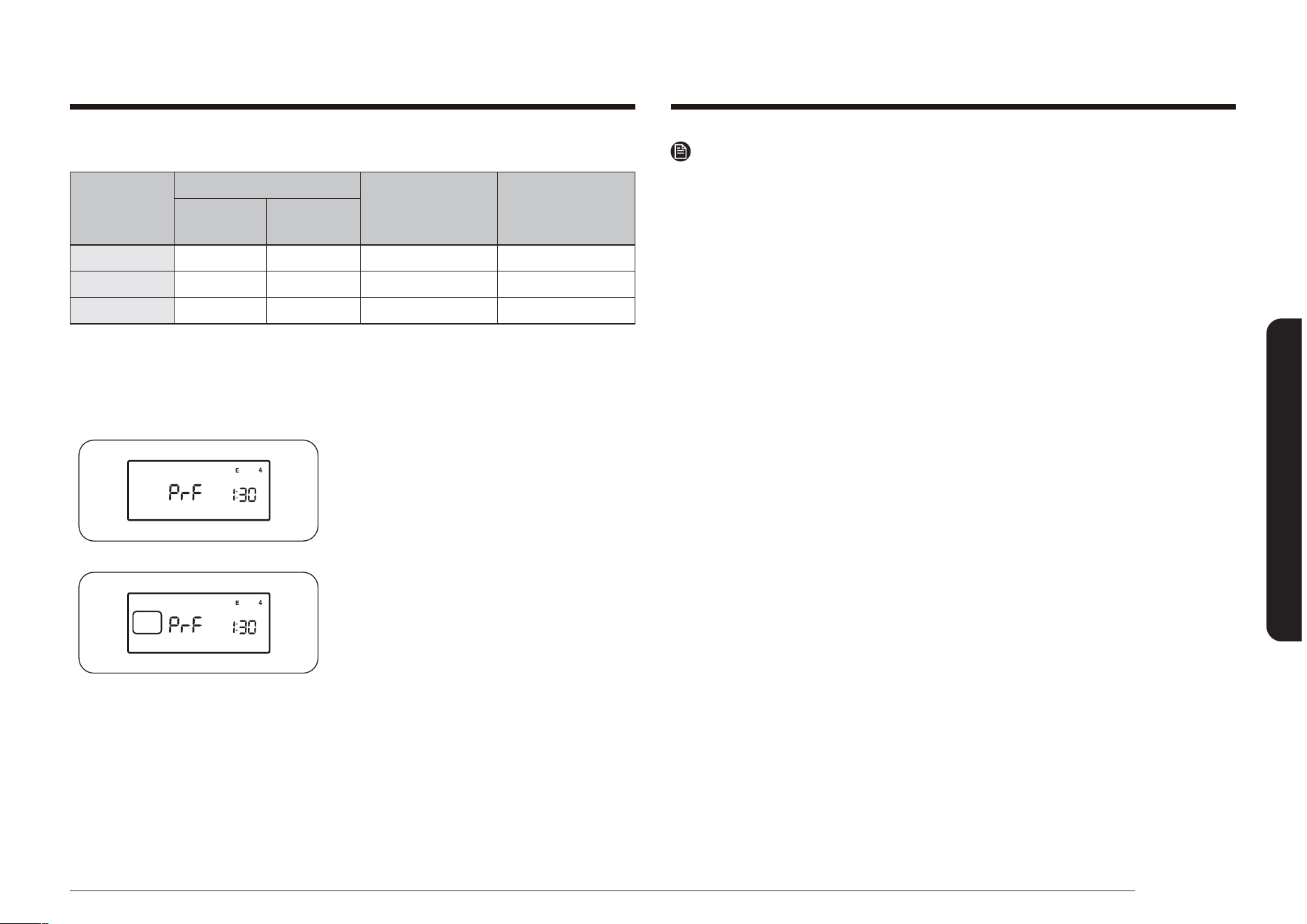
Español 51
Funcionamiento del horno
Nota
• Si presiona la tecla Bread Proof (Entibiar pan para leudado) cuando la
temperatura del horno es superior a los 100°F, la palabra Hot (Caliente)
aparecerá en la pantalla. Dado que estas funciones producen mejores
resultados si se inician cuando el horno esta frío, le recomendamos que
aguarde hasta que el horno se haya enfriado y “Hot” (Caliente) desaparezca de
la pantalla.
• Para evitar reducir la temperatura del horno y extender el tiempo de leudado,
no abra la puerta del horno si no fuese necesario.
• Controle el pan y alimentos similares para evitar que se excedan en este
proceso.
• No utilice el modo de entibiar para calentar los alimentos ni para mantenerlos
calientes. En esta función, el horno no estará lo sucientemente caliente como
para mantener los alimentos a temperaturas seguras. Cómo usar la función
calentar.
• Para obtener mejores resultados, coloque la masa en un plato en el horno en
la parrilla 3 o 4 y cubra la masa con un paño o con un envoltorio plástico. (Es
posible que el plástico deba engancharse debajo del recipiente para que el
ventilador del horno no lo vuele.)
Guía para deshidratar
Categoría
Posición de la parrilla
Peso
recomendado
(oz)
Temp. óptima
Una
parrilla
Varias
parrillas
Verduras 3 o 4 2 y 5 9 a 21 100-150 °F
Frutas 3 o 4 2 y 5 9 a 21 100-150 °F
Carnes 3 o 4 2 y 5 14 a 30 145-175 °F
Entibiar pan para leudado
Esta función mantiene un ambiente tibio que favorece la acción de las levaduras.
Cómo ajustar el horno para entibiar para leudado
1. Ingresar el modo de entibiar para
leudado.
Presione la tecla Bread Proof (Entibiar
pan para leudado).
2. Active la función de entibiar para
leudado. Presione la tecla. Esta función
automáticamente genera la temperatura
óptima para el proceso de leudado y,
por ende, no le corresponde ningún
ajuste de temperatura.
3. Presione la tecla OFF/CLEAR (APAGAR/
BORRAR) en cualquier momento para
desactivar esta función.
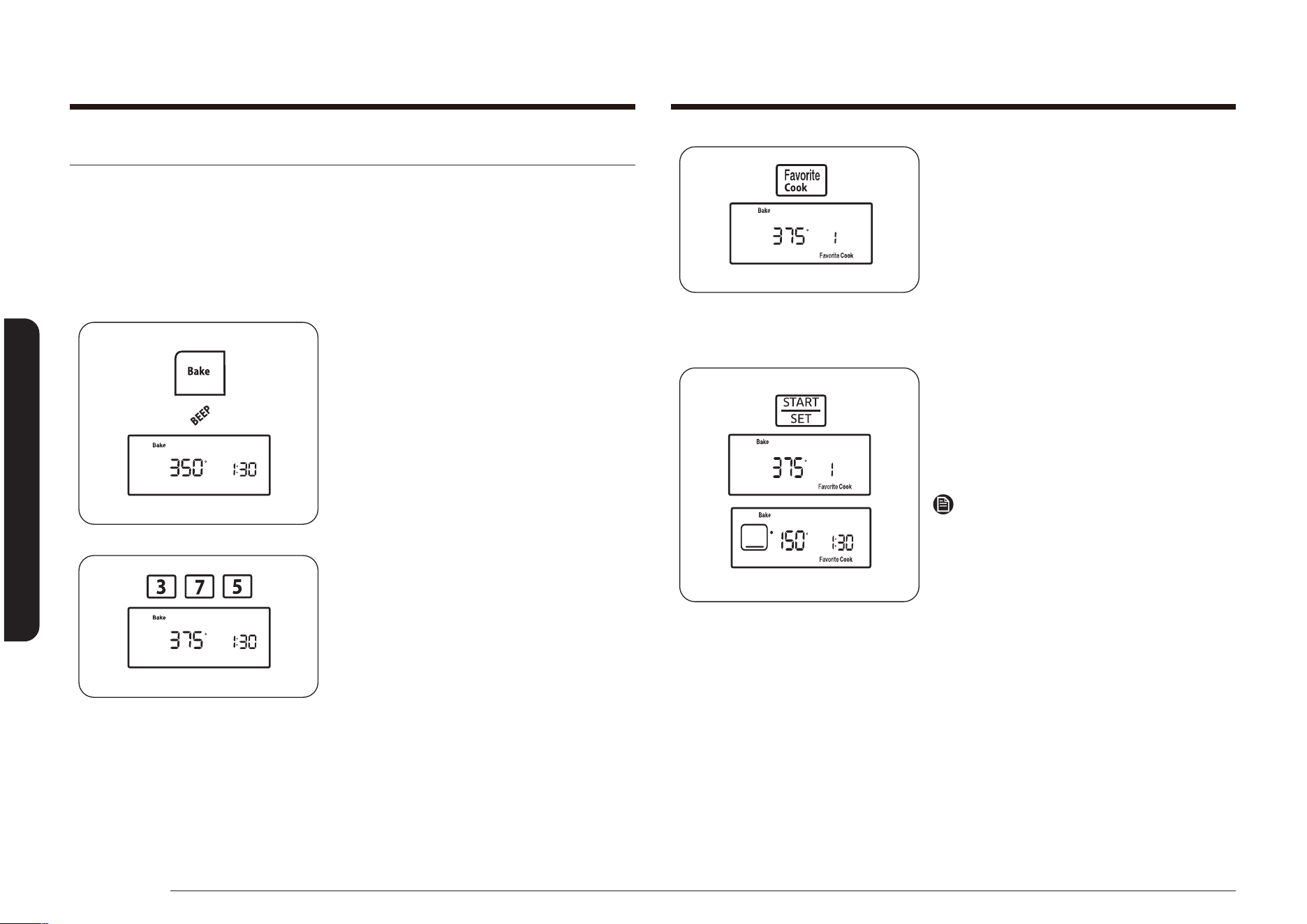
52 Español
Funcionamiento del horno
Funcionamiento del horno
3. Presione la tecla Favorite Cook (Cocción
favorita) una vez para guardar estos
ajustes en la Receta 1, dos veces para
guardarlos en la Receta 2 o tres veces
en la Receta 3.
El número y el ajuste correspondientes
se mostrarán en la pantalla y Favorite
Cook (Cocción favorita) parpadeará
debajo del ajuste de cocción favorita
seleccionado para esa receta.
4. Presione la tecla START/SET (INICIO/
CONFIGURAR).
La pantalla mostrará el último ajuste de
temperatura establecido o de Cocción
favorita utilizado y la hora del día
actual.
Nota
Presione la tecla START/SET (INICIO/
CONFIGURAR) una vez para guardar el
ajuste de Cocción favorita o dos veces para
guardar e iniciar la Cocción favorita en el
ajuste seleccionado.
Cocción favorita
La función Cocción favorita le permite preprogramar hasta 3 funciones de cocción
o ajustes de receta favorita distintos para que puedan recuperarse e iniciarse con
solo tocar un botón. Puede usar solo Hornear, Hornear por convección o Asar por
convección como una opción de Cocción favorita. No puede usar ninguna de las
funciones de Inicio retardado como opción de Cocción favorita.
Cómo seleccionar una cocción favorita
1. Presione la tecla para el funcionamiento
en la cocción que desea almacenar, por
ej., Bake (Hornear). El horno emitirá una
señal sonora cada vez que se presione
la tecla.
La temperatura predeterminada,
350° parpadeará en la pantalla. Si la
temperatura predeterminada es la
temperatura deseada de cocción, pase
directamente al paso 3.
2. Presione las teclas numéricas para
ingresar la temperatura de cocción
deseada (por ejemplo, 3, 7, 5).
La temperatura de cocción seleccionada
parpadeará en la pantalla.
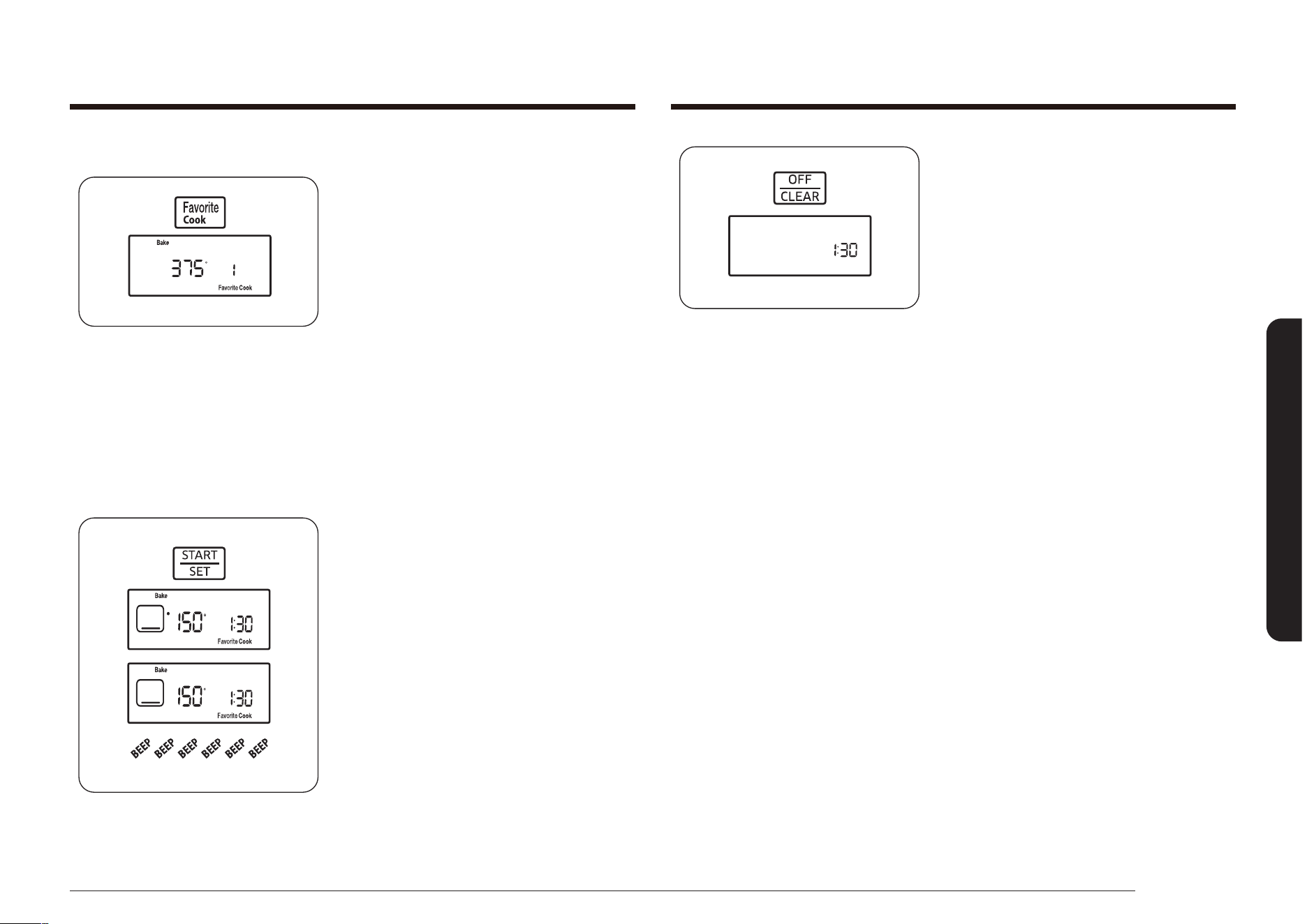
Español 53
Funcionamiento del horno
4. Coloque la comida en el horno y cierre
la puerta del horno. El precalentamiento
es muy importante para obtener buenos
resultados en el horneado o el asado al
horno.
5. Cuando nalice la cocción, retire los
elementos, cierre la puerta del horno y
presione la tecla OFF/CLEAR (APAGAR/
BORRAR).
El horno se apagará y la pantalla
mostrará la hora del día.
Cómo usar o recuperar una selección de cocción favorita
1. Coloque la parrilla del horno en la
posición deseada.
2. Presione la tecla Favorite Cook (Cocción
favorita). Para recuperar el ajuste de
la cocción favorita de su posición de
almacenamiento, presione la tecla
Favorite Cook (Cocción favorita) como
se muestra a continuación:
1 vez para la Receta 1,
2 veces para la Receta 2,
3 veces para la Receta 3.
Favorite Cook (Cocción favorita)
parpadeará debajo del ajuste de cocción
favorita seleccionado en la pantalla para
esa receta.
3. Presione la tecla START/SET (INICIO/
CONFIGURAR).
A “•” parpadeará a la izquierda de la
temperatura predeterminada o real
hasta que se alcance la temperatura
seleccionada. El horno emitirá una
señal sonora 6 veces. La temperatura
predeterminada o real, la función de
cocción, el icono de función de cocción y
la hora del día aparecerán en la pantalla.
Cuando el horno alcanza la temperatura
de cocción deseada, emite una señal
sonora 6 veces.
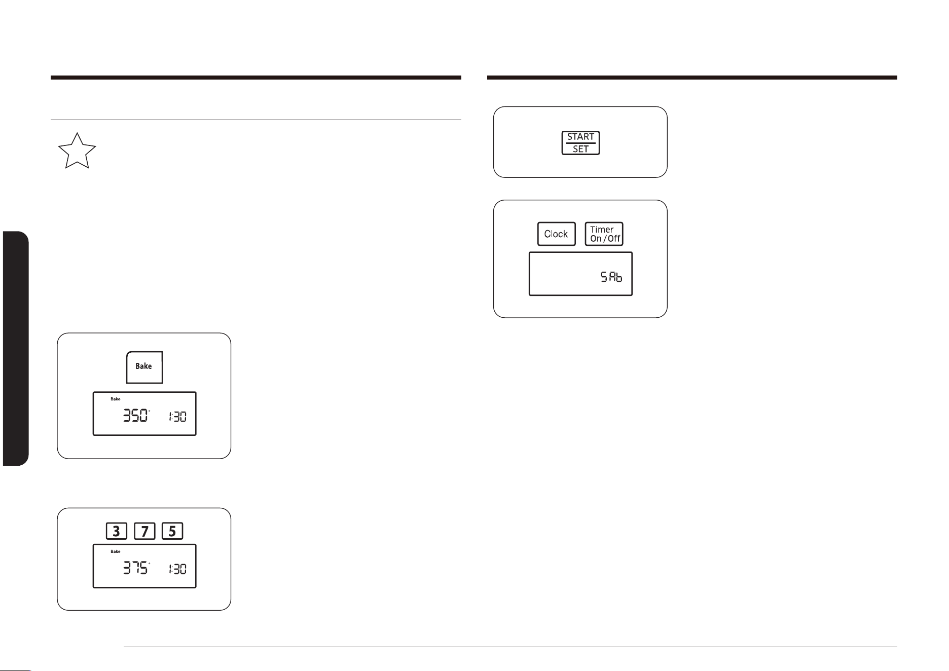
54 Español
Funcionamiento del horno
Funcionamiento del horno
4. Presione la tecla START/SET (INICIO/
CONFIGURAR).
5. Mantenga presionadas las teclas
Clock (Reloj) y Timer On/Off (Activar/
Desactivar temporizador) a la vez
durante 3 segundos.
En la pantalla se verá SAb. Se
desactivarán las señales del horno, los
LED de la pantalla y todos los controles
del horno, excepto las teclas de
números, Bake (Hornear), Cooking Time
(Tiempo de cocción), START/SET (INICIO/
CONFIGURAR) y OFF/CLEAR (APAGAR/
BORRAR).
En aproximadamente 20 segundos, el
panel de control hará “clic” y el horno
comenzará el proceso de iluminación
y precalentamiento. Después de que el
horno alcance la temperatura de cocción
seleccionada, continuará cocinando a
esa temperatura hasta que el tiempo de
cocción haya transcurrido o la función
Shabat se cancele.
La pantalla no contará regresivamente
el tiempo de cocción establecido, pero
el horno se apagará al nal del tiempo
jado.
Función Shabat
K
(Para uso en el Shabat y otras fechas sagradas judías)
Para obtener asistencia adicional, pautas para el uso adecuado y una
lista completa de modelos con la función Shabat, visite el sitio web en
http:\\www.star-k.org.
La función Shabat solo puede utilizarse con los ajustes Hornear y Tiempo
de cocción. El horno funcionará a la temperatura establecida y permanecerá
encendido hasta que se cancele la función Shabat o nalice el tiempo de cocción
establecido. Cuando se selecciona Shabat, esta función anula las funciones de
ahorro de energía preestablecidas de fábrica. Se desactivarán todas las luces de la
pantalla, las señales del horno, la mayoría de las teclas de control y el ventilador
de convección.
Cómo congurar la función Shabat
1. Coloque la parrilla del horno en la
posición deseada. Consulte la página 35.
2. Presione la tecla Bake (Hornear). El
horno emitirá una señal sonora cada vez
que se presione una tecla hasta que se
active la función Shabat.
La temperatura predeterminada,
350°, parpadeará en la pantalla. Si la
temperatura predeterminada es la
temperatura deseada de cocción, pase
directamente al paso 4.
3. Presione las teclas numéricas para
ingresar la temperatura de cocción
deseada (por ejemplo, 3, 7, 5).
La temperatura de cocción seleccionada
parpadeará en la pantalla.
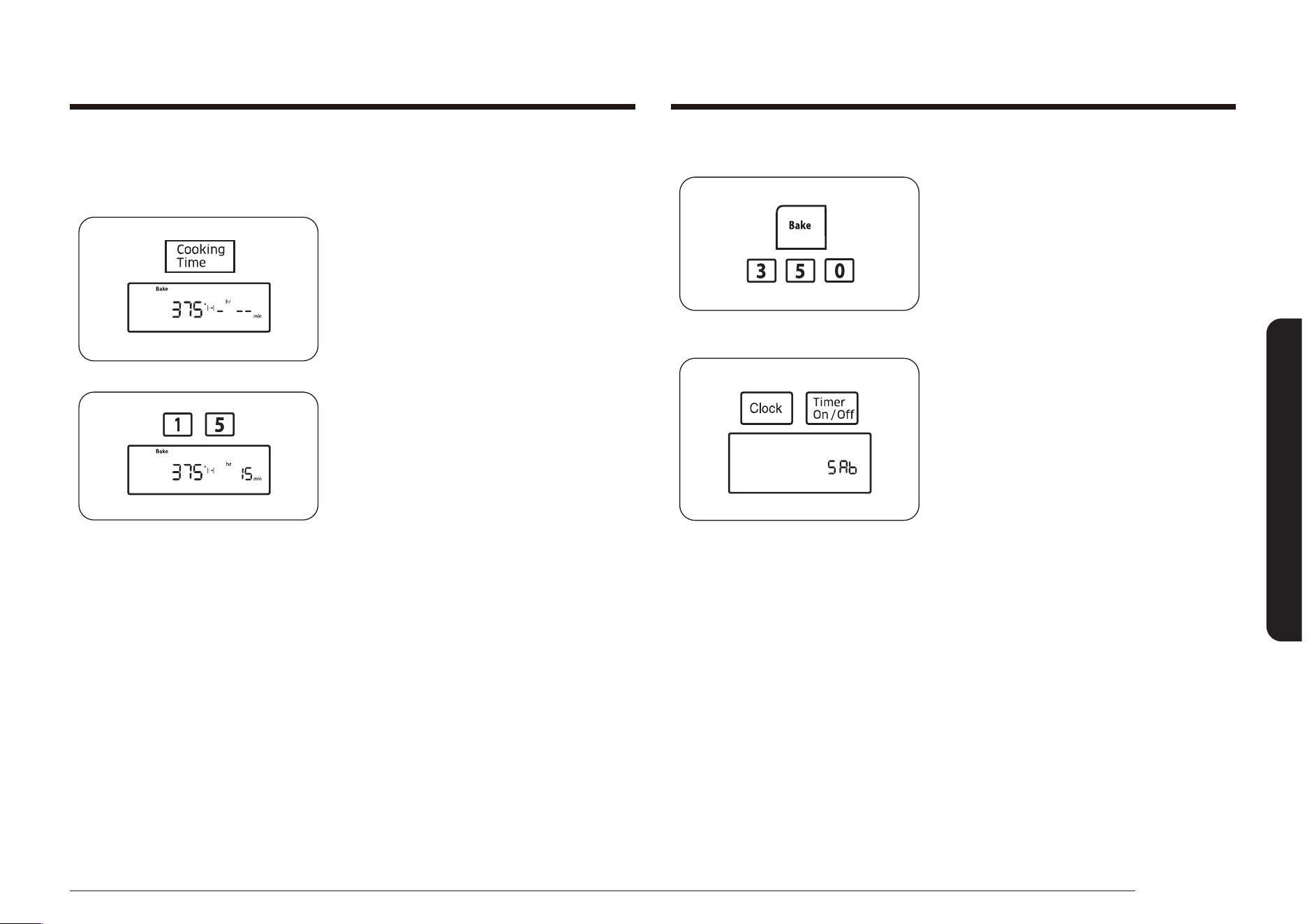
Español 55
Funcionamiento del horno
Cómo cambiar la temperatura y salir de la función shabat
Para cambiar una temperatura de horneado
programada, presione la tecla Bake
(Hornear), ingrese la nueva temperatura
de horneado y luego presione la tecla
START/SET (INICIO/CONFIGURAR). En
aproximadamente 20 segundos, el panel de
control hará “clic” y el horno completará la
cocción a la nueva temperatura.
Para salir de la función Shabat, mantenga
presionadas las teclas Clock (Reloj) y Timer
On/Off (Activar/Desactivar temporizador)
a la vez durante 3 segundos. La pantalla
mostrará la hora del día.
Cómo congurar el horneado programado en el modo shabat
Para congurar el horneado programado en el modo Shabat, siga los pasos 1 a 3
de Cómo congurar la función Shabat y luego siga los pasos a continuación.
1. Presione la tecla Cooking Time (Tiempo
de cocción).
La pantalla mostrará -
hr
--
min
.
(Los caracteres de hr y min no se
muestran en los modelo NX58*560***,
NX58*751***.)
2. Presione las teclas numéricas para
ingresar el tiempo de cocción deseado.
El indicador START (INICIO) parpadeará
en la pantalla. Puede congurar el
tiempo en cualquier extensión de tiempo
entre 1 minuto y 9 horas y 99 minutos.
Proceda con el paso 4 de Cómo
congurar la función Shabat.
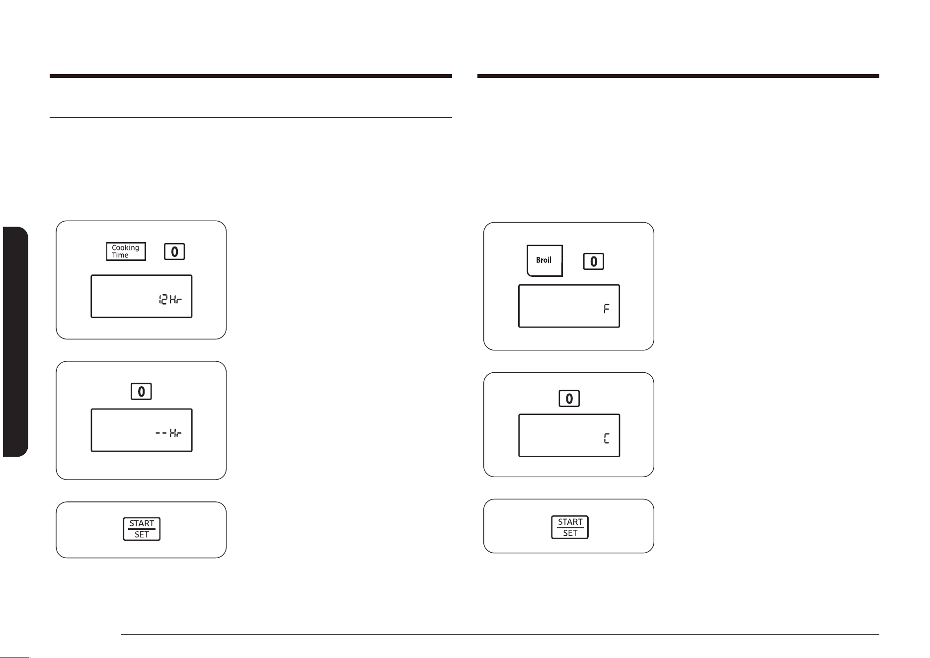
56 Español
Funcionamiento del horno
Funcionamiento del horno
Selección de temperatura en fahrenheit o centígrados
Se puede programar el control del horno para que las temperaturas se muestren
en grados Fahrenheit o Centígrados.
El horno viene de fábrica congurado para mostrar las temperaturas en
Fahrenheit.
Cómo cambiar la pantalla de Fahrenheit a Centígrados o de Centígrados a
Fahrenheit.
1. Presione las teclas Broil (Asar a
la parrilla) y 0 a la vez durante 3
segundos.
En la pantalla se verá F (Fahrenheit) o
C (Centígrados).
El ajuste predeterminado es F.
2. Presione la tecla 0 para seleccionar F o
C. Al presionar la tecla 0 se alterna entre
F y C.
3. Presione la tecla START/SET (INICIO/
CONFIGURAR) para guardar y establecer
la selección de temperatura.
Funciones adicionales
Ahorro de energía de 12 horas/3 horas
Con esta función, si usted se olvidase de que el horno está encendido, el control
apagará el horno automáticamente transcurridas 12 horas si está operando en
funciones de horneado y transcurridas 3 horas si está asando a la parrilla.
Cómo activar y desactivar la función de ahorro de energía transcurridas 12 horas.
1. Presione las teclas Cooking Time
(Tiempo de cocción) y 0 a la vez durante
3 segundos.
La pantalla mostrará 12 Hr (cierre en 12
horas) o -- Hr (sin cierre).
El valor predeterminado es 12 Hr.
2. Presione la tecla 0 para seleccionar ON
(12 Hr) u OFF (-- Hr).
3. Presione la tecla START/SET (INICIO/
CONFIGURAR) para guardar e iniciar el
ajuste de la función.
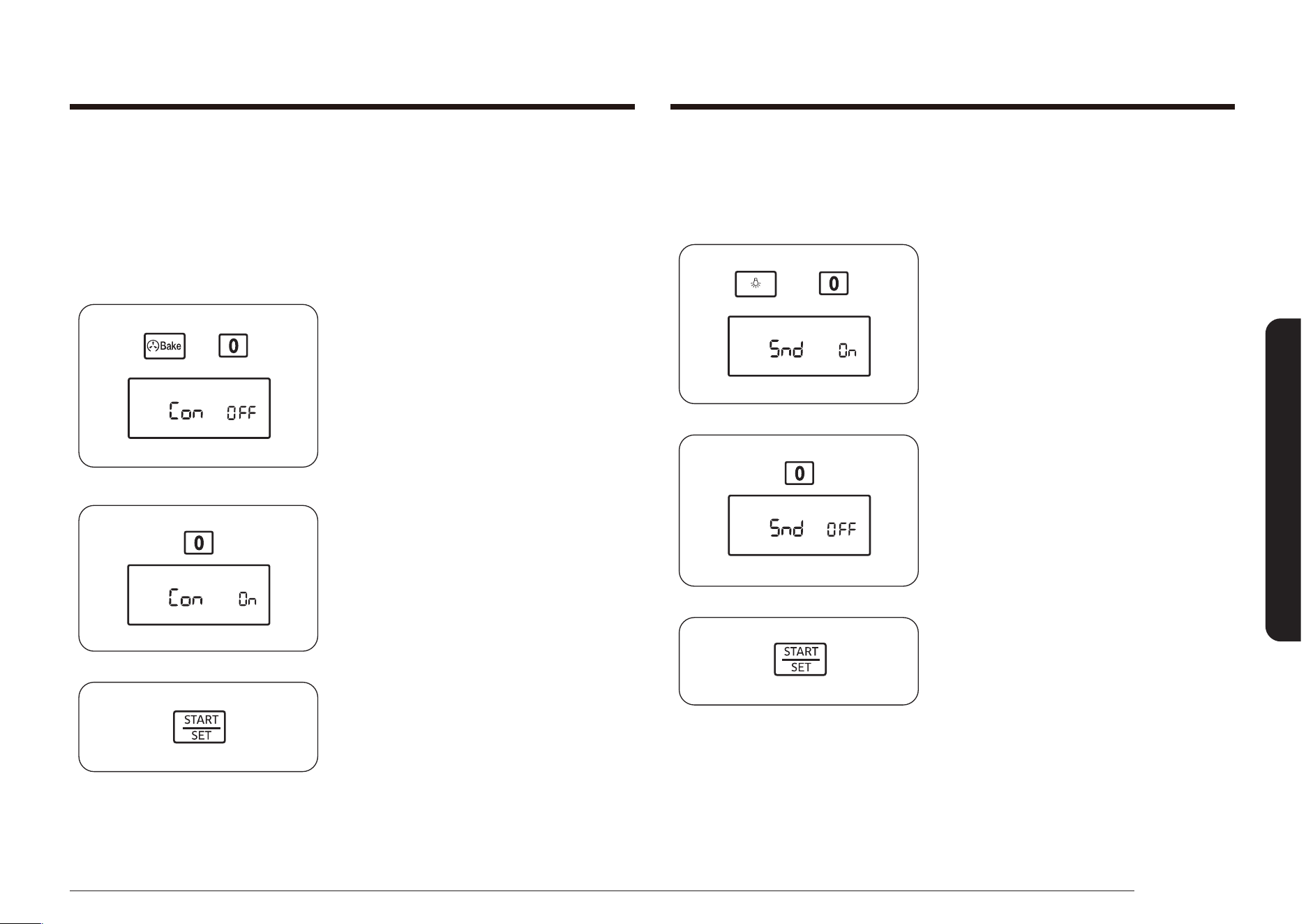
Español 57
Funcionamiento del horno
Activar o desactivar las señales sonoras
Mediante esta función se pueden congurar los controles del horno para que
funcionen silenciosamente.
Cómo activar o desactivar el sonido.
1. Presione las teclas Luz del horno y 0 a
la vez durante 3 segundos.
La pantalla mostrará Snd On
(Sonido activado) o Snd OFF (Sonido
desactivado).
El ajuste predeterminado es Snd On
(Sonido activado).
2. Presione la tecla 0 para seleccionar
Snd On (Sonido activado) o Snd OFF
(Sonido desactivado).
3. Presione la tecla START/SET (INICIO/
CONFIGURAR) para guardar y establecer
el ajuste de la señal sonora.
Función de auto-conversión por convección
Cuando se hornea por convección, la función de auto-conversión por convección
automáticamente convertirá las temperaturas normales ingresadas a las
temperaturas correspondientes para convección. Esta función se encuentra
activada de manera tal que en la pantalla se verá la temperatura real convertida
(reducida).
Cómo activar o desactivar la función de auto-conversión.
1. Presione las teclas Convection Bake
(Hornear por convección) y 0 a la vez
durante 3 segundos.
En la pantalla se verá Con On
(Conversión activada) (habilitado) o
Con OFF (Conversión desactivada)
(deshabilitado).
La conguración predeterminada es Con
OFF (Convección desactivada).
2. Presione la tecla 0 para seleccionar
Con On (Conversión activada) o Con OFF
(Conversión desactivada).
3. Presione la tecla START/SET (INICIO/
CONFIGURAR) para guardar y establecer
la función de autoconversión.
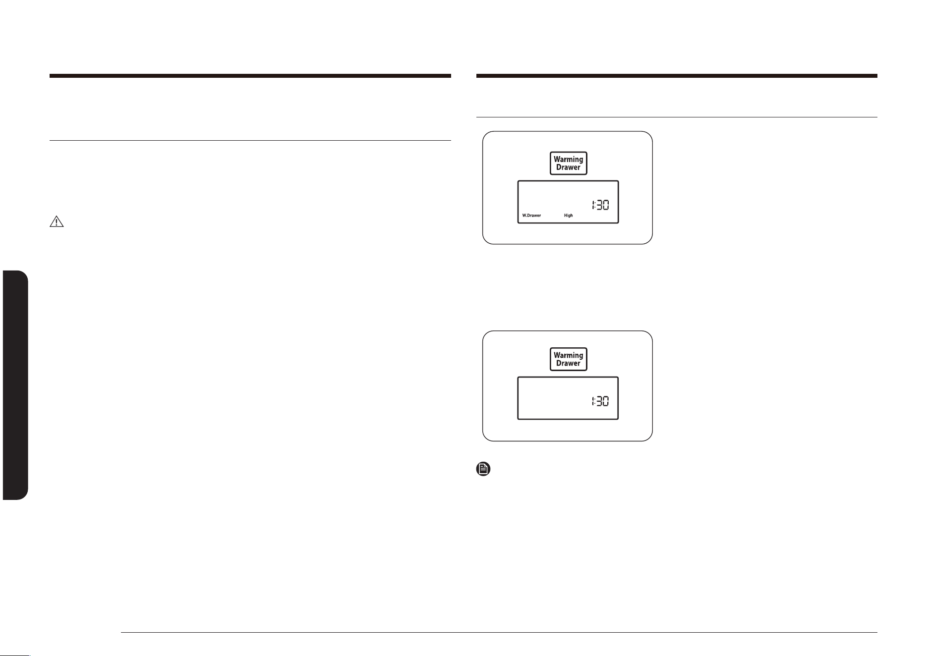
58 Español
Uso del cajón de calentamiento
Uso del cajón de calentamientoUso del cajón de calentamiento
Acerca del cajón de calentamiento
(Modelo NX58*565*** solamente)
El Cajón de calentamiento le permite mantener comidas cocidas y calientes a
temperaturas aptas para servir. Siempre comience con alimentos calientes. No use
el cajón de calentamiento para calentar o recalentar la comida fría.
Prevea que el cajón de calentamiento demora unos 25 minutos para precalentarse.
PRECAUCIÓN
No use recipientes o envoltorios plásticos en el cajón de calentamiento. El plástico
se derretirá con el contacto directo con el cajón. El plástico derretido puede
resultar imposible de quitar y la garantía no cubre este problema.
• No revista el cajón de calentamiento con papel de aluminio. El papel de
aluminio es un excelente aislante de calor y el calor quedará atrapado debajo
de él. Esto alterará el funcionamiento del cajón y podría dañar su acabado
interior.
• No coloque líquidos o agua dentro del cajón de calentamiento.
• Todos los alimentos colocados dentro del cajón de calentamiento deben
cubrirse con una tapa o papel de aluminio. Cuando se mantienen calientes
pasteles y panes, la tapa debe tener una abertura para permitir que escape la
humedad.
• Retire los cucharones o elementos similares antes de colocar recipientes en el
cajón de calentamiento.
• Para mantener caliente la comida, utilice el recipiente de cocción o transérala
a un plato de servir resistente a la temperatura.
• No se puede utilizar el cajón de calentamiento durante un ciclo de auto-
limpieza.
• El cajón de calentamiento se apagará automáticamente después de 3 horas.
Encendido y apagado del cajón de calentamiento
1. Presione la tecla Warming Drawer
(Cajón de calentamiento) una vez para
la temperatura de calentamiento baja,
dos veces para la temperatura de
calentamiento media, tres veces para
la temperatura de calentamiento alta
o cuatro veces para apagar el cajón de
calentamiento.
El Warming Drawer (Cajón de
calentamiento) y la luz de temperatura
seleccionada aparecerán en la pantalla
y el cajón de calentamiento comenzará
a calentar.
2. Para apagar el cajón de calentamiento,
presione la tecla Warming Drawer
(Cajón de calentamiento) hasta que el
cajón se apague.
Nota
Presionar la tecla OFF/CLEAR (APAGAR/BORRAR) no apaga el cajón de
calentamiento.
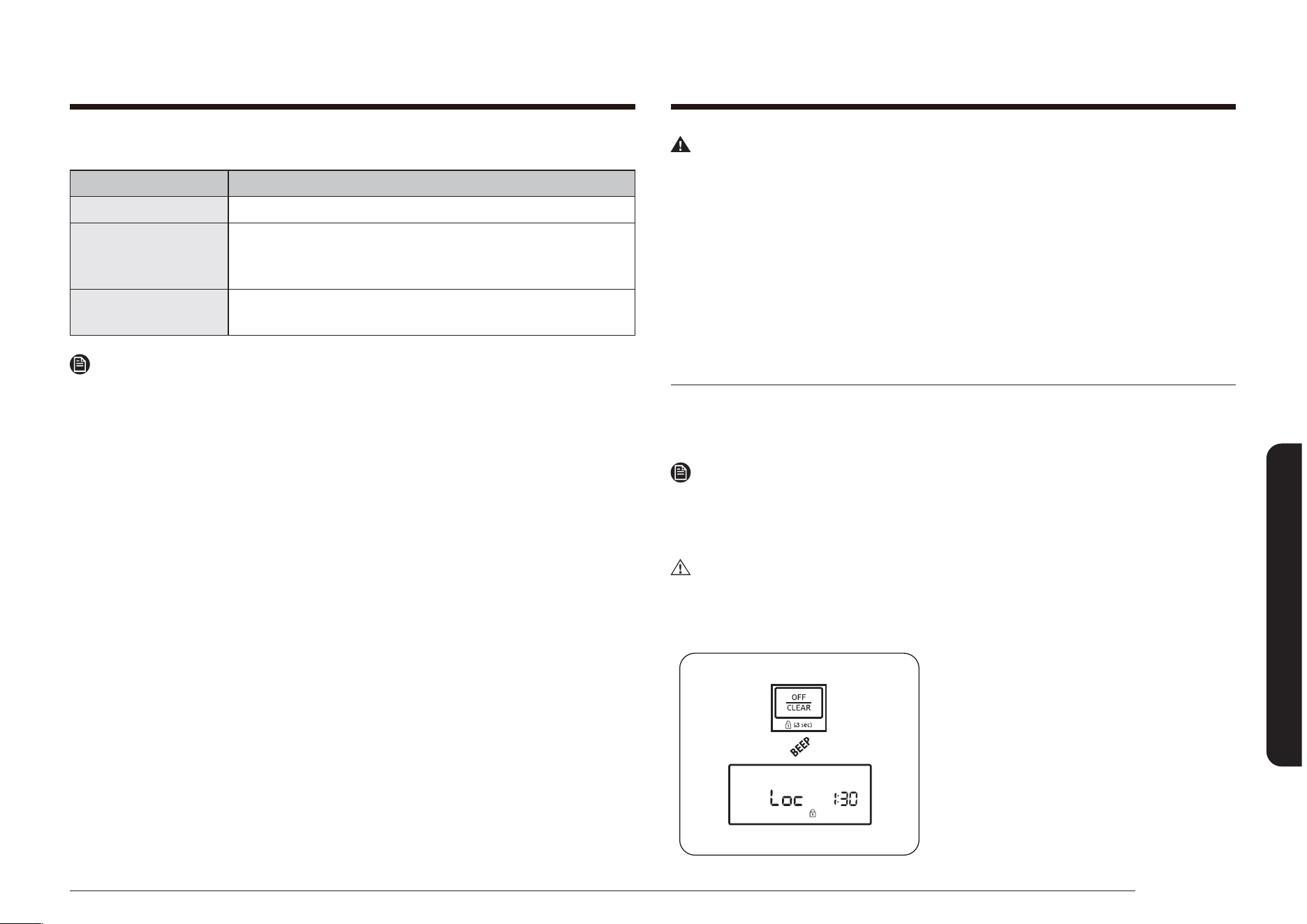
Español 59
Mantenimiento de su electrodoméstico
Regulaciones recomendadas
AJUSTE DEL CAJÓN TIPO DE COMIDA*
BAJO Panecillos blandos, platos de mesa vacíos
MED
Carnes asadas (res, cerdo, cordero), guisos, verduras,
huevos, pastelería, galletas, panecillos crocantes, jugos
de cocción y salsas
ALTO
Aves, chuletas de cerdo, hamburguesas, pizza, tocino,
alimentos fritos
Nota
* Se pueden colocar en el cajón de calentamiento diferentes tipos de alimentos
a la vez. Para obtener el mejor resultado, no deje los alimentos en el cajón de
calentamiento por más de 1 hora. No deje cantidades pequeñas de comida o
alimentos sensibles a la temperatura, tales como huevos, por más de 30 minutos.
Mantenimiento de su electrodoméstico
ADVERTENCIA
• Siempre asegúrese de que los controles estén en OFF (Apagado) y que todas
las supercies estén frías antes de retirar y/o limpiar cualquiera de las partes
de la estufa. Esto evitará que sufra quemaduras.
• Si por alguna razón se separa la estufa de la pared, asegúrese de que vuelva
a conectarse el dispositivo anti inclinación luego de volver a colocar la estufa
en su lugar. Si se omite esta precaución, la estufa podría inclinarse y causar
lesiones personales.
• Tenga cuidado de no lesionarse cuando limpie el electrodoméstico (por dentro
o por fuera). Puede lesionarse con los bordes alados del electrodoméstico.
Cuidado y limpieza del horno
Los paneles de control del horno y los quemadores superiores pueden limpiarse
fácilmente con un paño húmedo o un limpiavidrios. Las áreas muy sucias pueden
limpiarse con agua jabonosa tibia.
Nota
Nunca use lana de acero ni limpiadores abrasivos.
Proteja la supercie de los objetos losos.
Todos estos elementos pueden dañar la supercie.
PRECAUCIÓN
Use el guante durante la limpieza.
Panel de control del horno
1. Para bloquear los controles del horno
y la puerta del horno, mantenga
presionada la tecla OFF/CLEAR
(APAGAR/BORRAR) durante 3 segundos.
Esto evita el funcionamiento accidental
del horno y que el artefacto se incline.
El horno emitirá una señal sonora y la
pantalla mostrará Loc (Bloqueo), la hora
del día y el icono de Bloqueo.
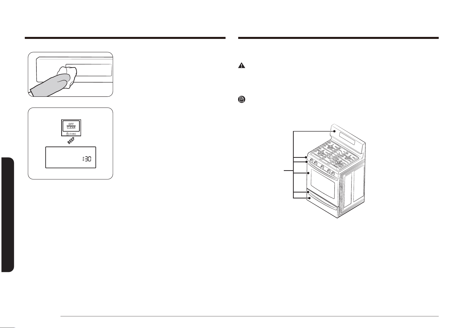
60 Español
Mantenimiento de su electrodoméstico
Mantenimiento de su electrodoméstico
2. Limpie las salpicaduras con un paño
húmedo, limpiavidrios o agua jabonosa
tibia.
3. Para desbloquear los controles y la
puerta, mantenga presionada la tecla
OFF/CLEAR (APAGAR/BORRAR) durante
3 segundos.
Para desbloquear solo los controles, deje
la puerta levemente abierta y mantenga
presionada la tecla OFF/CLEAR
(APAGAR/BORRAR) durante 3 segundos.
El horno emitirá una señal sonora y
Loc (Bloqueo) y el icono de Bloqueo
desaparecerán de la pantalla. Cierre la
puerta del horno, si la está manteniendo
abierta.
Supercies de acero inoxidable
ADVERTENCIA
No use una esponja de lana de acero ni limpiadores abrasivos sobre supercies de
acero inoxidable. Las esponjas y los limpiadores abrasivos rayarán la supercie y
dañarán su acabado.
Nota
Para evitar cualquier decoloración o mancha de grasa, recomendamos limpiar y
eliminar todo derrame, mancha y grasa de la estufa después de cada uso.
Supercies
de acero
inoxidable

Español 61
Mantenimiento de su electrodoméstico
1. Limpie cualquier derrame con un paño
suave húmedo.
2. Aplique un limpiador de acero
inoxidable aprobado a un paño húmedo
limpio o una toalla de papel. Limpie una
pequeña área con cuidado siguiendo
las instrucciones del limpiador. El acero
inoxidable siempre debe limpiarse en la
dirección del grano del acero inoxidable,
si corresponde.
3. Seque y lustre con un paño limpio,
suave y seco.
4. Repita los pasos 2 y 3 según sea
necesario.
ADVERTENCIA
No rocíe ningún tipo de limpiador en los oricios del panel de distribución. Dentro
de estos oricios hay interruptores de encendido que transportan la corriente que
prende los quemadores superiores. Rociarlos podría dañar la estufa.
Parrillas del horno
• Si las parrillas se dejan en el horno durante un ciclo de auto-limpieza, su color
virará a tonos azulados y el acabado se volverá opaco. Una vez nalizado el
ciclo de auto-limpieza y cuando se haya enfriado el horno, frote los laterales
de las parrillas con un papel encerado o con un paño humedecido con una
pequeña cantidad de aceite. Esto permitirá que las parrillas se deslicen más
fácilmente en sus carriles.
• Las parrillas deslizantes pueden limpiarse a mano con un limpiador abrasivo
o de lana de acero. Durante la limpieza, tenga cuidado de que no entre agua o
limpiador en los deslizadores a los costados de la parrilla.
Nota
• No las limpie en una lavavajillas.
• Si se hace difícil retirar o colocar la parrilla, aplique una pequeña cantidad
de aceite de cocina en las guías de las parrillas del horno. No pase aceite de
cocina en los deslizadores.
• Si se torna difícil deslizar la parrilla, puede ser necesario lubricarla usando
lubricante de grato.
Nota
• Para pedir lubricante de grato, llame a nuestro centro de atención al cliente al
1-800-SAMSUNG (726-7864) o visite nuestra página web
(www.samsung.com/us/support, www.samsung.com/ca/support (English) o
www.samsung.com/ca_fr/support (French)) y busque la referencia
DG81-01629A.
• Si quiere comprarlo directamente, visite nuestro distribuidor de piezas en línea
en http://www.samsungparts.com/Default.aspx.
Lubricación de los deslizadores
1. Quite la parrilla del horno. Consulte
cómo quitar la parrilla deslizante
en la sección USO DE LA PARRILLA
DESLIZANTE.
2. Extienda totalmente la parrilla sobre
una mesa o mesada. Se puede colocar
periódico debajo de la parrilla para una
limpieza fácil.
3. Si hay suciedad en las guías de los
deslizadores, límpiela usando una toalla
de papel. (Cualquier lubricante de grato
quitado debe volverse a colocar - vea
los pasos 4 a 7.
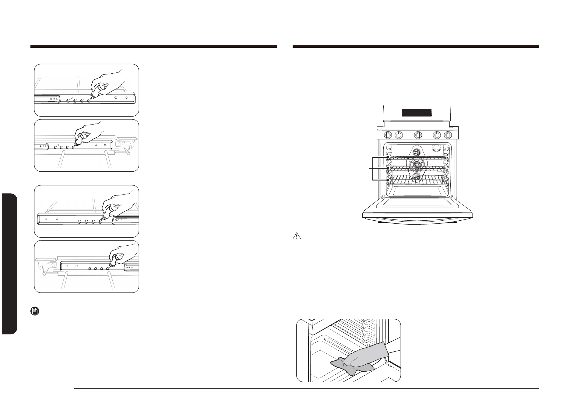
62 Español
Mantenimiento de su electrodoméstico
Mantenimiento de su electrodoméstico
4. Agite el lubricante de grato antes de
abrirlo. Empezando con el mecanismo
de deslizamiento de la izquierda (parte
frontal y trasera) de la parrilla, coloque
cuatro (4) gotas pequeñas de lubricante
en las dos (2) guías inferiores del
deslizador cerca de las correderas de
rodamiento.
5. Repita para el mecanismo de
deslizamiento derecho (parte frontal y
trasera) de la parrilla.
6. Abra y cierre la parrilla varias veces
para distribuir el lubricante.
7. Vuelva a colocar la tapa del lubricante y
agítelo nuevamente. Dé vuelta la parrilla
y repita los pasos 3, 4, 5 y 6.
8. Cierre la parrilla, dela vuelta con el lado
correcto hacia arriba y colóquela en el
horno. Consulte cómo instalar la parrilla
deslizante en la sección USO DE LA
PARRILLA DESLIZANTE.
Nota
No rocíe la rejilla deslizante con aceite para cocinar u otro lubricante en aerosol.
Parrillas del horno
Para mantener las parrillas brillosas y que luzcan como nuevas, retire las parrillas
del horno y lávelas a mano con agua jabonosa caliente con una esponja de pulir
con jabón o una esponja plástica.
Parrillas
del horno
PRECAUCIÓN
No deje las parrillas en el horno durante un ciclo de auto-limpieza. El calor
extremo en el ciclo de auto limpieza decolorará en forma permanente las parrillas
del horno y hará que les resulte difícil deslizarse.
Si deslizar las parrillas se vuelve difícil, frote los rieles laterales con papel de
cera o un paño que contenga una pequeña cantidad de aceite para cocinar. Esto
permitirá que las parrillas se deslicen más fácilmente en los carriles.
Horno
Use el guante durante la limpieza.

Español 63
Mantenimiento de su electrodoméstico
Cuidado y limpieza de la cubierta de cocción
Controles de los quemadores superiores
1. Asegúrese de que todas las perillas de
los quemadores superiores estén en la
posición OFF (Apagado).
2. Retire las perillas de control de los
vástagos de la válvula de control de los
quemadores superiores.
PRECAUCIÓN
No limpie las perillas de control en una
lavavajillas. No son aptas para lavarse en
lavavajillas.
3. Limpie las perillas de control en agua
jabonosa tibia. Enjuague y seque por
completo todas las supercies (incluidos
el oricio del vástago y la parte
posterior).
ADVERTENCIA
No use limpiadores en aerosol sobre
el panel de control de los quemadores
superiores. Si el rocío ingresa a los oricios
de las válvulas podría entrar en contacto
con los componentes eléctricos y causar
la muerte, lesiones personales o daños al
producto.
4. Limpie las supercies de acero
inoxidable con un limpiador para acero
inoxidable en un paño suave y húmedo.
Consulte la página 60.
Puerta del horno
ADVERTENCIA
No permita que la humedad ingrese a la puerta ni entre en contacto con las juntas
durante la limpieza. Si la humedad ingresa al montaje o la junta de la puerta, la
junta se dañará.
No mueva ni
limpie las juntas.
Áreas grises de
limpieza a mano
La puerta del horno tiene múltiples supercies que requieren distintas técnicas
de limpieza. La junta en la supercie interior de la puerta del horno nunca debe
limpiarse ni moverse para limpiar otras supercies. La junta está confeccionada
con un material tejido que es esencial para un cierre bien sellado.
La supercie interior de la puerta fuera de la juta debe limpiarse a mano con agua
jabonosa caliente y una esponja de pulir plástica con jabón. Enjuague y seque bien
con un paño limpio suave. No moje la junta ni permita que la humedad ingrese al
montaje de la puerta.
La supercie interna de la puerta dentro de la junta y el vidrio del interior de la
puerta se limpian durante el ciclo de auto-limpieza del horno.
La supercie externa de la puerta es de acero inoxidable y debe limpiarse
siguiendo las instrucciones de la página 60.
La supercie de vidrio externa puede limpiarse con un limpiavidrios o agua
jabonosa tibia con un buen enjuague. No permita que la humedad ingrese al
montaje de puerta.

64 Español
Mantenimiento de su electrodoméstico
Mantenimiento de su electrodoméstico
2. Levante y retire las rejillas de los
quemadores de la cubierta de cocción.
Tome nota de los tamaños de los
quemadores y las ubicaciones de todos
los quemadores superiores.
3. Retire las tapas de los quemadores de
los cabezales.
4. Retire los cabezales de los quemadores
que están en los distribuidores de las
válvulas y los electrodos de encendido.
5. Limpie todas las partes desmontables de
los quemadores en agua jabonosa tibia.
No use esponjas de lana de acero ni
limpiadores abrasivos en ninguna parte
de los quemadores.
6. Enjuague bien y seque por completo
todas las partes antes de que se vuelvan
a montar.
Nota
• Después de la limpieza, conrme que
las aberturas de los puertos de los
quemadores no estén atascadas.
• Sacuda para quitar el exceso de agua
y deje que los cabezales del quemador
y las tapas se sequen bien. Si coloca el
quemador central invertido permitirá
que el agua se escurra con mayor
facilidad.
• No limpie ninguno de los componentes
de los quemadores en una lavavajillas.
5. Vuelva a colocar las perillas de
control en la posición OFF (Apagado)
insertándolas en los vástagos de las
válvulas de control.
Rejillas y montajes de los quemadores superiores
1. Apague todos los controles y asegúrese
de que todas las piezas estén frías.
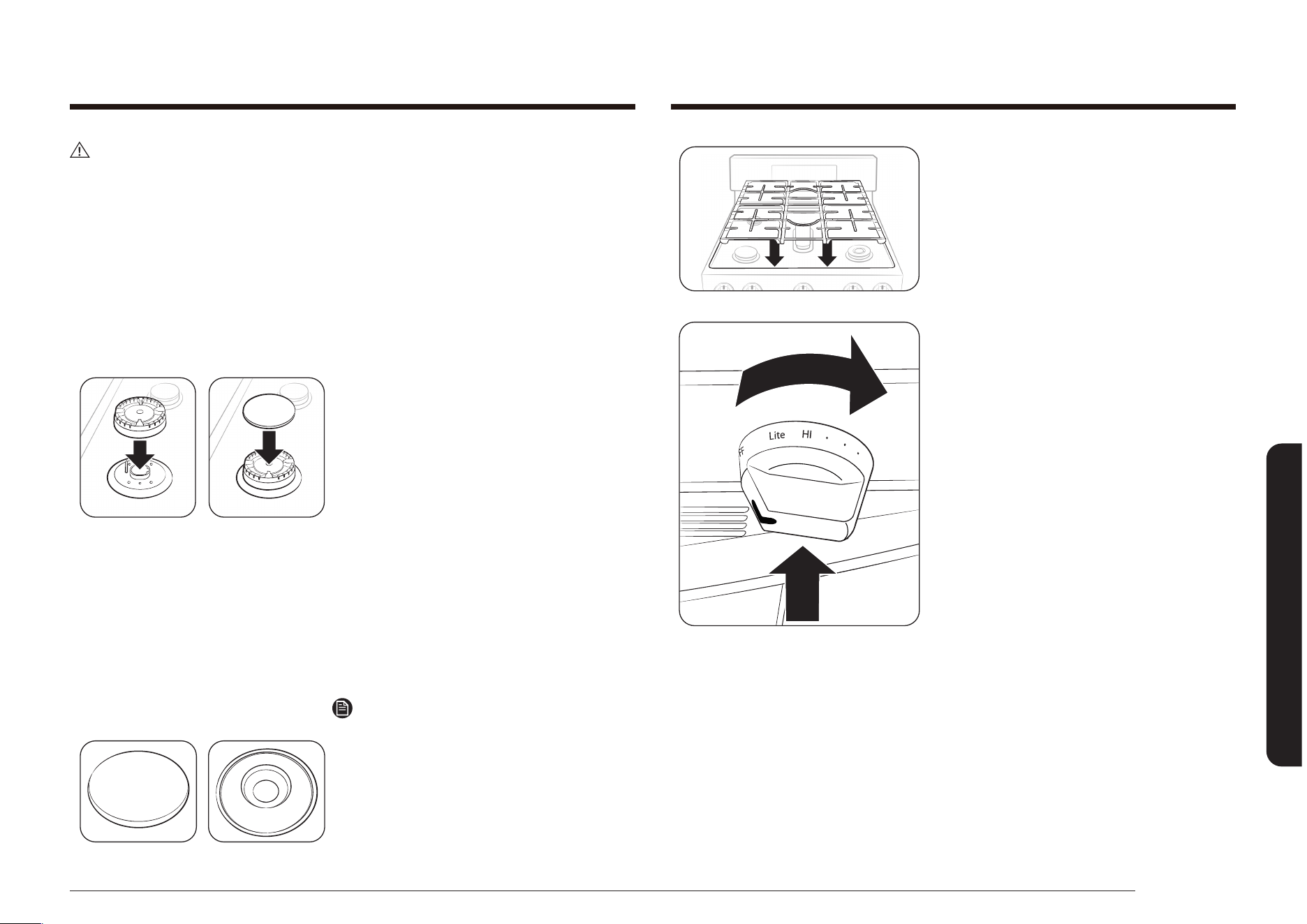
Español 65
Mantenimiento de su electrodoméstico
9. Vuelva a colocar las rejillas de los
quemadores sobre la parte superior de
la cubierta de cocción de la estufa.
10. Presione y gire cada perilla de control
de los quemadores superiores a la
posición LITE (Encender), deje que
se encienda cada quemador y, luego,
vuelva a ajustar la perilla de control a
un ajuste del quemador para asegurarse
de que cada quemador funcione
correctamente.
PRECAUCIÓN
• Los electrodos de encendido no son desmontables. No intente retirarlos por la
fuerza.
• Para evitar el astillado, no golpee las rejillas y tapas entre sí, o contra
supercies duras, tales como utensilios de hierro fundido.
• Es posible que el cabezal del quemador se bloquee con comida o polvo. Limpie
el cabezal si parece estar bloqueado. Si limpia el cabezal con agua, ensámblelo
solo después de que esté completamente seco. Si el cabezal está húmedo,
podría impedir que se enciendan los quemadores.
• Para evitar que se caigan las rejillas, asegúrese de retirar ambos lados primero.
• No intente retirar la tapa del quemador central ovalado del cabezal.
7. Coloque los cabezales de los
quemadores sobre las mismas válvulas
en las que estaban antes de extraerlos.
El oricio del lateral de los cabezales de
los quemadores va sobre los electrodos.
Los cabezales de los quemadores
están correctamente instalados cuando
quedan planos sobre la parte superior
de las válvulas.
8. Coloque las tapas de los quemadores
sobre los cabezales.
Estas además deben quedar planas
en la parte superior de los cabezales
de los quemadores para garantizar un
funcionamiento adecuado y seguro.
Quemador a fuego lento de
precisión (TD)
Nota
Las tapas del quemador a fuego lento de
precisión (TD) y del quemador de doble aro
interior (DD) pueden utilizarse de manera
intercambiable.
Supercie plana Línea cóncava
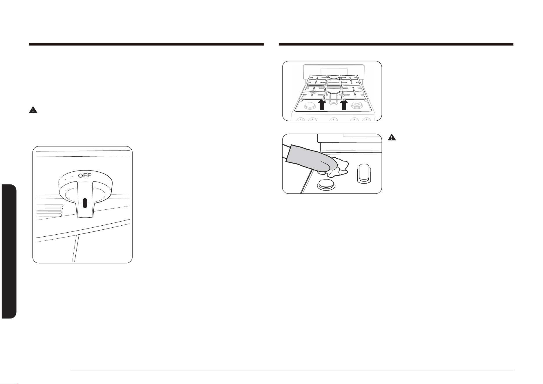
66 Español
Mantenimiento de su electrodoméstico
Mantenimiento de su electrodoméstico
2. Cuando las supercies se enfrían, retire
las rejillas de los quemadores.
ADVERTENCIA
No retire ni levante la cubierta durante la
limpieza. Hacerlo podría dañar las líneas
de gas que llevan a los distribuidores de
los quemadores superiores, generando un
mal funcionamiento o un funcionamiento
peligroso.
3. Limpie la supercie de la cubierta con
agua jabonosa tibia y un paño húmedo
suave. Si el derrame pasa debajo de
un quemador superior, retire la tapa y
el cabezal del quemador superior para
acceder y limpiar el derrame.
4. Enjuague con agua limpia y seque y
lustre con un paño suave seco.
5. Vuelva a montar los componentes de los
quemadores (si se retiraron) y vuelva a
colocar las rejillas de los quemadores.
Supercie de la cubierta
La supercie de la cubierta es una supercie de esmalte de porcelana. Para evitar
que esta supercie se opaque, limpie y seque los derrames apenas suceden. Los
alimentos con mucho ácido (tomate, chucrut, jugos de fruta, etc.) o los alimentos
con un alto contenido de azúcar pueden causar manchas opacas si se dejan secar.
ADVERTENCIA
No use una esponja de lana de acero ni limpiadores abrasivos sobre supercies de
esmalte de porcelana. Las esponjas y los limpiadores abrasivos rayarán y dañarán
la supercie.
1. Asegúrese de que todos los quemadores
superiores estén en OFF (Apagado).

Español 67
Mantenimiento de su electrodoméstico
Cómo retirar y volver a colocar la puerta del horno
ADVERTENCIA
• La puerta del horno es muy pesada. No la levante de la manija y tenga cuidado
de no dejar caer la puerta cuando la retira. El manejo inadecuado podría causar
lesiones personales.
• Desconecte la energía eléctrica de la estufa antes de retirar la puerta del
horno. Esto evita que el horno se encienda accidentalmente mientras se retira
la puerta.
Para retirar la puerta
1. Abra completamente la puerta del
horno.
Recambio de la luz del horno
La luz del horno es una bombilla para electrodomésticos estándar de 40 watts.
Se encenderá automáticamente al abrirse la puerta del horno. También puede
encenderse y apagarse cuando la puerta del horno se cierra presionando la tecla
Luz del horno en el panel de control del horno.
Nota
La luz del horno no funcionará durante un ciclo de auto-limpieza.
ADVERTENCIA
Desconecte la energía eléctrica de la estufa antes de reemplazar la luz del horno.
Esto evitará cualquier lesión personal debido a una descarga eléctrica.
Cubierta y
bombilla de la luz
del horno
1. Asegúrese de que el horno y la bombilla
se encuentren fríos.
2. Abra la puerta del horno.
Nota
Si las parrillas del horno representan un
obstáculo, pueden cambiarse de lugar o
retirarse antes de cambiar la luz del horno.
3. Gire la cubierta de vidrio de la luz en
el ángulo trasero superior derecho en
sentido contrario a las agujas del reloj
para retirarla.
4. Gire la bombilla en sentido contrario a
las agujas del reloj para retirarla de su
casquillo.
5. Reemplace la bombilla con una nueva
bombilla para electrodomésticos de 40
watts. Gire la bombilla en el sentido de
las agujas del reloj hasta que quede bien
colocada en el casquillo.
6. Vuelva a colocar la cubierta de vidrio
girándola en el sentido de las agujas del
reloj hasta que quede bien colocada.
7. Cierre la puerta del horno y vuelva a
conectar la energía eléctrica a la estufa.
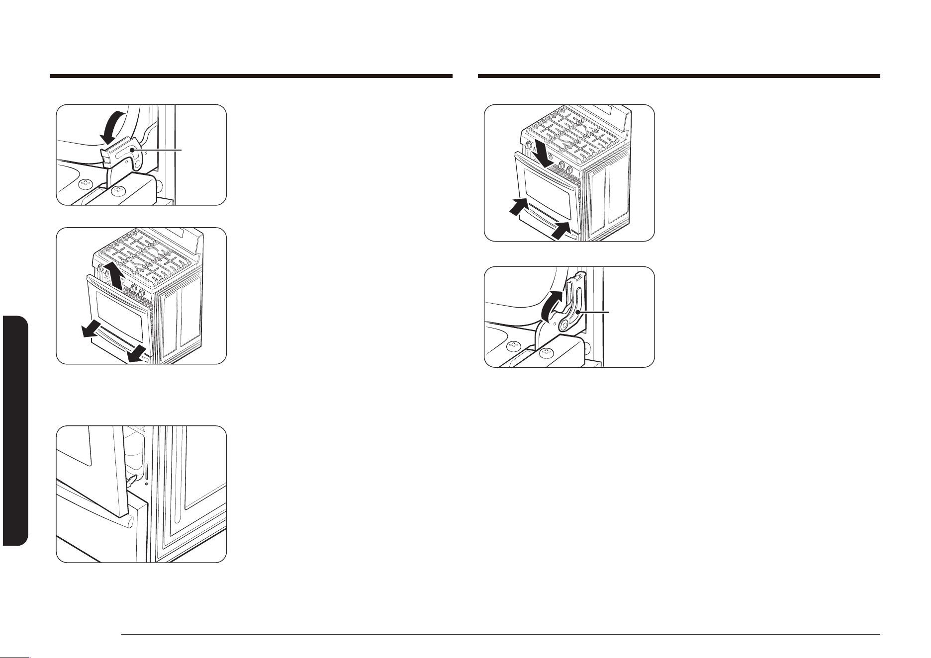
68 Español
Mantenimiento de su electrodoméstico
Mantenimiento de su electrodoméstico
2. Sujete con rmeza los dos lados de la
puerta.
3. Mientras sostiene la puerta del horno,
inserte ambos brazos de las bisagras
de la puerta en las ranuras en la parte
inferior del marco de la puerta. Con la
puerta abierta alrededor de 5 grados,
los brazos de la bisagra se podrán
deslizar hacia dentro y hacia abajo.
Traba
de la
bisagra
4. Abra completamente la puerta del
horno.
Si la puerta no se abre por completo,
los brazos de las bisagras no están
correctamente insertados en las ranuras
en la parte inferior de la puerta.
5. Bloquee ambas trabas de las bisagras.
Empuje cada traba hacia arriba contra el
marco frontal de la cavidad del horno.
6. Cierre la puerta.
7. Vuelva a conectar la electricidad a la
estufa.
Traba
de la
bisagra
2. Desbloquee las dos trabas de las
bisagras. Empuje cada traba de bisagra
hacia abajo hacia el marco de la puerta
para desbloquearla, para que queden
como se indica en la ilustración a la
derecha.
3. Cierre la puerta en la posición
de remoción de la puerta,
aproximadamente 5 grados de la
posición vertical.
4. Sujete rmemente ambos lados de la
puerta y levántela y hale hacia afuera
hasta que el brazo de la bisagra esté
fuera de las ranuras en la parte inferior
de la puerta del horno.
5. Coloque la puerta con cuidado en un
lugar seguro.
Para volver a colocar la puerta
1. Asegúrese de que los brazos de las
bisagras estén bloqueados y en la
posición de remoción.

Español 69
Mantenimiento de su electrodoméstico
Para volver a colocar el cajón de calentamiento
Riel de la guía
giratoria derecha
1. Coloque los extremos de los rieles de
la guía giratoria de extensión completa
en los rieles laterales en la abertura del
cajón.
2. Empuje el cajón para cerrarlo y presione
los ganchos de bloqueo en su lugar.
Cómo retirar y volver a colocar el cajón de calentamiento
(Modelo NX58*565***)
Para retirar y limpiar el cajón de calentamiento
1. Tire del cajón hacia afuera hasta que se
detenga.
Gancho de
bloqueo del
cajón derecho
Gancho de
bloqueo del
cajón izquierdo
2. Localice los ganchos de bloqueo junto
a la parte posterior de cada riel de
extensión completa de la guía giratoria.
Con las dos manos, baje el gancho de
la izquierda y levante el gancho de la
derecha para liberarlos. Termine de
sacar el resto del cajón.
3. Limpie el cajón en agua jabonosa tibia.
Enjuague y seque bien.
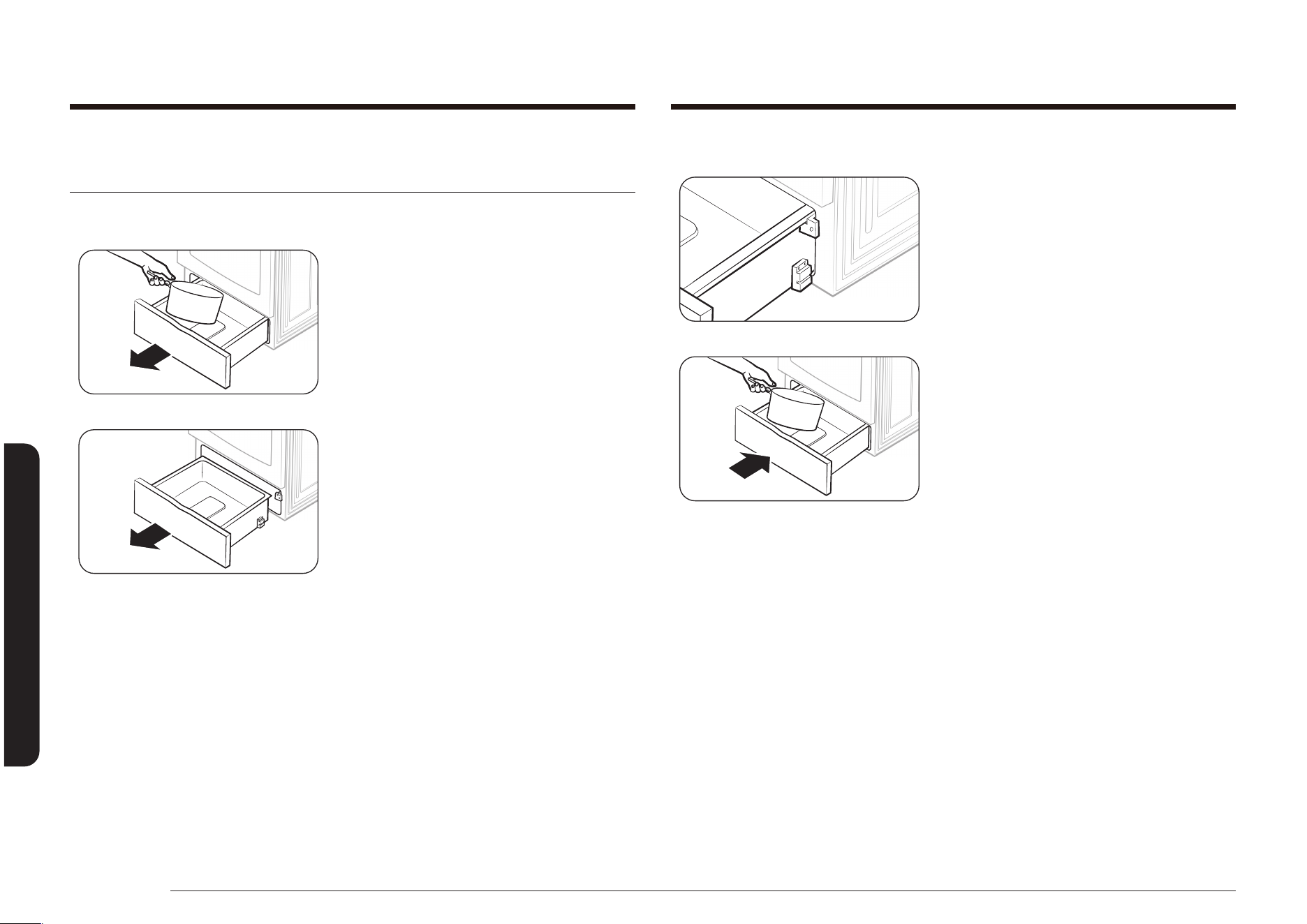
70 Español
Mantenimiento de su electrodoméstico
Mantenimiento de su electrodoméstico
Para volver a colocar el cajón de almacenamiento
1. Coloque la parte superior de los dos
laterales del cajón en las aberturas
de las dos guías de nailon del cajón y
empuje hacia adentro lo suciente como
para que sostengan el cajón.
2. Vuelva a colocar todo el contenido
almacenado y empuje el cajón hacia
adentro mientras levanta levemente el
frente para cerrarlo.
Cómo retirar y volver a colocar el cajón de almacenamiento
(Modelo NX58*560***, NX58*751***)
Para retirar el cajón de almacenamiento
1. Saque el cajón y retire todo el contenido
almacenado.
2. Mientras sostiene el cajón, tírelo hacia
afuera hasta que la parte superior de
los laterales del cajón salgan de las dos
guías de nailon del cajón. Luego, levante
para retirar el cajón.
3. Limpie el cajón en agua jabonosa tibia.
Enjuague y seque bien.

Español 71
Mantenimiento de su electrodoméstico
Antes de un ciclo de auto-limpieza
Nota
Retire las parrillas. Dejar las parrillas del horno en el horno durante un ciclo de
auto-limpieza decolorará las parrillas y hará que les sea difícil deslizarse hacia y
desde su posición.
• Asegúrese de que la función de bloqueo
de la puerta esté apagada y el horno
esté frío. De lo contrario, el ciclo de
auto-limpieza no comenzará.
• En el modelo NX58*565***, asegúrese
de que el cajón de calentamiento
esté apagado. La auto-limpieza no
comenzará cuando el cajón esté
encendido.
ADVERTENCIA
NO use los quemadores superiores mientras el horno funciona en el modo de auto-
limpieza.
• Un icono de Loc (Bloqueo) que parpadea
indica que la puerta del horno está en
proceso de bloquearse.
• Cuando el icono de Loc (Bloqueo) está
activado, la puerta del horno está
bloqueada.
Horno auto-limpiante
El horno auto-limpiante utiliza altas temperaturas (mucho más altas que las
temperaturas de cocción) para eliminar por incineración los restos de grasa y otros
residuos o reducirlas a no polvo de ceniza que se puede limpiar con un paño
húmedo.
ADVERTENCIA
No seguir estar precauciones podría tener como consecuencia que se produzcan
daños al horno, incendio o lesiones personales.
• No deje niños pequeños sin vigilancia cerca de la estufa durante el ciclo de
auto-limpieza. Las supercies externas de la estufa pueden volverse muy
calientes.
• Algunos pájaros son muy sensibles a los humos de un horno auto-limpiante.
Lleve a los pájaros a una sala bien ventilada alejada de la estufa.
• No recubra el horno, las parrillas del horno ni la parte inferior del horno
con papel de aluminio. Hacerlo podría tener como consecuencia una mala
distribución del calor, producir malos resultados de horneado y causar daños
permanentes al interior del horno. El papel de aluminio se derretirá y se
adherirá a las supercies interiores del horno.
• No fuerce la apertura de la puerta del horno durante el ciclo de auto-limpieza.
Esto dañará el sistema de traba automática de la puerta. La puerta se bloquea
automáticamente cuando se inicia el ciclo de auto-limpieza y se mantiene
bloqueada hasta que se cancela el ciclo y la temperatura del horno es inferior
a 350 °F.
• Tenga cuidado al abrir la puerta del horno después de un ciclo de auto-
limpieza. El horno aún estará MUY CALIENTE y podría salir aire caliente y
vapor al abrir la puerta.
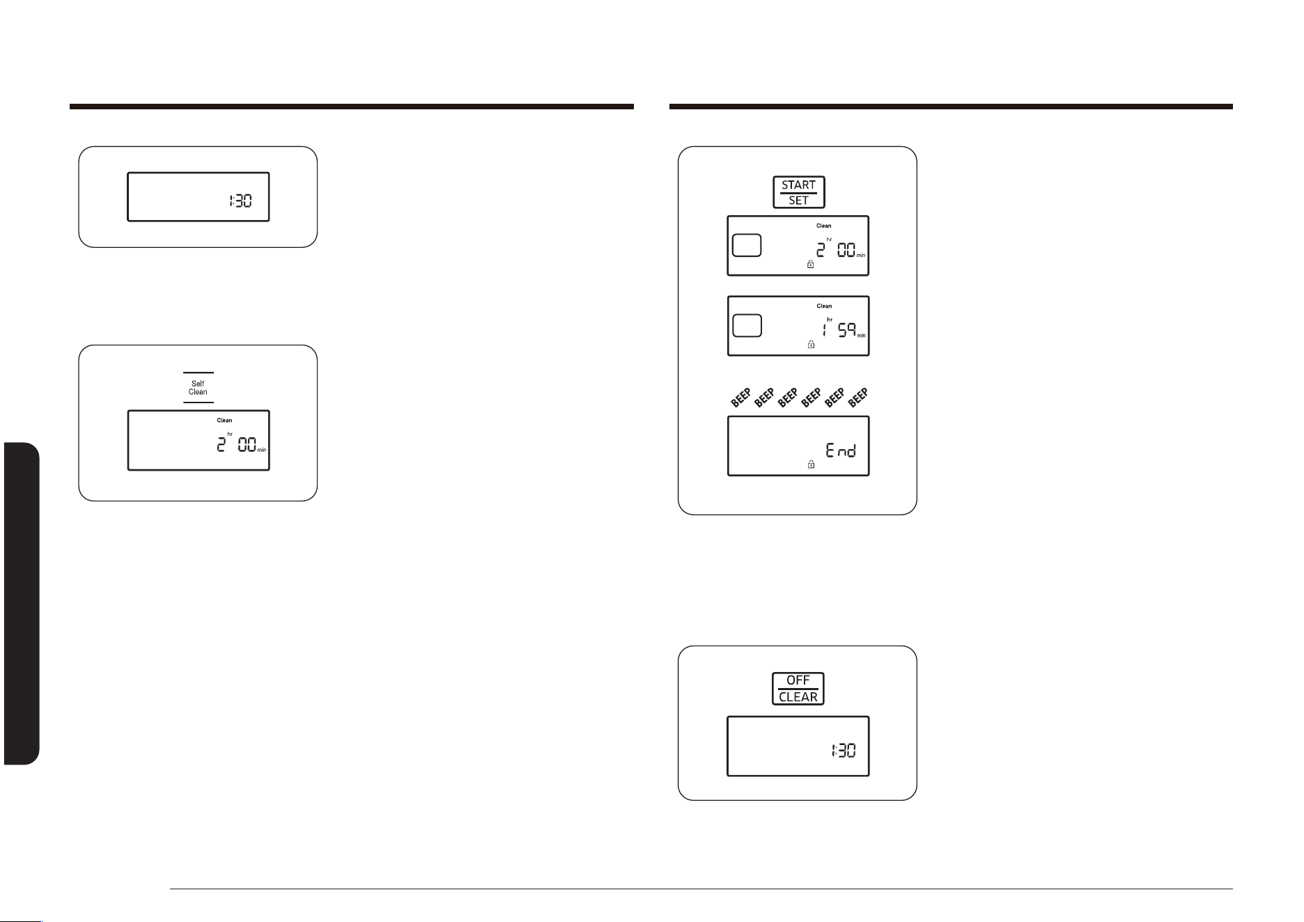
72 Español
Mantenimiento de su electrodoméstico
Mantenimiento de su electrodoméstico
3. Presione la tecla START/SET (INICIO/
CONFIGURAR) para iniciar el ciclo.
La pantalla mostrará Clean (Limpiar)
y el tiempo del ciclo de limpieza
seleccionado, y el icono de Bloqueo
parpadeará hasta que se bloquee la
puerta. Luego el icono de Bloqueo
permanecerá encendido hasta que el
ciclo nalice y la temperatura del horno
sea inferior a los 350 °F (177 °C).
La temperatura del horno aumentará
y mantendrá la temperatura de auto-
limpieza predeterminada mientras dure
el ciclo de limpieza seleccionado. La
pantalla mostrará la cuenta regresiva
del ciclo de limpieza en minutos y horas.
Cuando el tiempo pase, el horno se
apagará y emitirá una señal sonora 6
veces. End (Fin) aparecerá en la pantalla
y el icono de Bloqueo parpadeará.
Cuando la temperatura del horno cae
por debajo de los 350 °F (177 °C), la
puerta se desbloquea y el icono de
Bloqueo se apaga.
4. Presione la tecla OFF/CLEAR (APAGAR/
BORRAR).
La pantalla volverá a mostrar la hora
del día.
• Cuando aparece Loc (Bloqueo) en la
pantalla, esto indica que la función de
bloqueo de la puerta está activada.
Mantenga presionada la tecla OFF/
CLEAR (APAGAR/BORRAR) durante
3 segundos para desbloquear los
controles del horno.
Cómo programar el horno para auto-limpieza
1. Asegúrese de que la puerta del horno
esté bien cerrada.
2. Presione la tecla Self Clean (Auto-
limpieza) en el panel de control del
horno.
Presione la tecla una vez para un ciclo
de limpieza de 2 horas, dos veces para
un ciclo de 3 horas o tres veces para un
ciclo de 4 horas.
Presionar la tecla por cuarta vez volverá
a seleccionar el tiempo predeterminado
de 2 horas.
La pantalla mostrará Clean (Limpiar) y
el indicador Start (Inicio) parpadeará
debajo del tiempo del ciclo de limpieza
seleccionado.
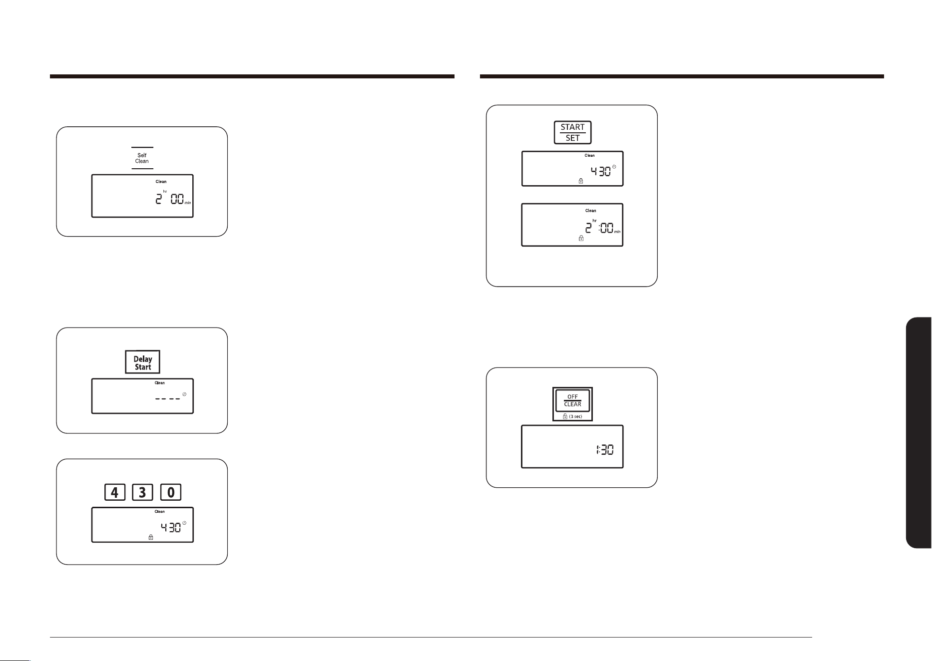
Español 73
Mantenimiento de su electrodoméstico
5. Presione la tecla START/SET (INICIO/
CONFIGURAR).
La pantalla mostrará la hora de Inicio
retardado y el icono de Bloqueo. La
traba de la puerta del horno se cerrará
automáticamente.
Cuando se llegue a la hora de inicio, el
horno se encenderá automáticamente e
iniciará el ciclo de limpieza programado.
Cómo cancelar la auto-limpieza
Es posible que se vea en la necesidad de detener o interrumpir el ciclo de auto-
limpieza debido a humo excesivo o fuego dentro del horno.
• Presione la tecla OFF/CLEAR (APAGAR/
BORRAR).
El horno se apagará. El icono de Bloqueo parpadeará debajo de la hora actual del
día en la pantalla. Cuando la temperatura del horno cae por debajo de los
350 °F (177 °C), la puerta del horno se desbloquea y el icono de Bloqueo se apaga.
Cómo diferir el inicio del proceso de auto-limpieza
1. Asegúrese de que la puerta del horno
esté bien cerrada.
2. Presione la tecla Self Clean (Auto-
limpieza) en el panel de control del
horno.
Presione la tecla una vez para un ciclo
de limpieza de 2 horas, dos veces para
un ciclo de 3 horas o tres veces para un
ciclo de 4 horas.
La pantalla mostrará Clean (Limpiar) y
el indicador Start (Inicio) parpadeará
debajo del tiempo del ciclo de limpieza
seleccionado.
3. Presione la tecla Delay Start (Inicio
retardado).
La pantalla mostrará Delay (Retardo) y
-- --.
4. Presione las teclas numéricas para
establecer la hora a la que desea que el
horno se encienda, por ej.: 4, 3, 0.
El indicador Start (Inicio) parpadeará
debajo de la hora de inicio retardado
seleccionada y Delay (Retardo) en la
pantalla.
74 Español
Solución de problemas
Solución de problemas
Después de la auto-limpieza
PRECAUCIÓN
Tenga cuidado al abrir la puerta del horno después de un ciclo de auto-limpieza. El
horno sigue estando muy caliente cuando la puerta se desbloquea. El aire caliente
y el vapor que salen podrían quemarlo.
• La temperatura interna del horno debe estar por debajo de los 350 °F para
que la traba automática de la puerta se desconecte. La traba de la puerta debe
desconectarse antes de que se pueda establecer otra función de cocción.
• Una vez que se enfrió el horno, limpie las supercies del horno con un paño
húmedo para retirar cualquier residuo de cenizas.
• Las manchas difíciles pueden limpiarse con un paño de lana de acero bien
enjabonado. Es posible utilizar un paño empapado en vinagre para quitar los
depósitos calcáreos. Enjuague bien después de limpiar.
• Si el horno no ha quedado limpio después de un ciclo, repita el ciclo. Si el
horno sigue estando caliente, aparecerá la palabra HOT (Caliente) en la pantalla
hasta que el horno esté lo sucientemente frío como para comenzar un nuevo
ciclo.
• La autolimpieza no opera durante las 2 horas siguientes a la ejecución del ciclo
de autolimpieza.
Solución de problemas
Solución de problemas
Samsung hace grandes esfuerzos para asegurar que usted no experimente
problemas con su nueva estufa de gas. Si experimenta un problema, como
primera medida busque la solución en la siguiente tabla. Si, luego de intentar
la solución sugerida, aún experimenta problemas, llame a Samsung al número
1-800-SAMSUNG (726-7864).
PROBLEMA CAUSA POSIBLE SOLUCIÓN
Hay olor a gas. Hay una fuga de gas.
La perilla del quemador
superior no está en posición
OFF (Apagado), pero el
quemador no está encendido.
Libere el ambiente, el
edicio o el área de todos los
ocupantes.
Llame inmediatamente al
proveedor de gas desde el
teléfono de un vecino. No
llame desde su teléfono. El
teléfono es eléctrico y podría
causar una chispa que podría
prender fuego el gas. Siga las
instrucciones del proveedor
de gas.
Si no puede comunicarse con
el proveedor de gas, llame al
departamento de bomberos.
Español 75
Solución de problemas
PROBLEMA CAUSA POSIBLE SOLUCIÓN
La estufa está
desnivelada.
El electrodoméstico fue
instalado incorrectamente.
Las patas niveladoras están
dañadas o desparejas.
Asegúrese de que el piso
esté nivelado, y sea sólido
y estable Si el piso está
combado o tiene una
pendiente, llame a un
carpintero.
Controle y nivele la estufa.
(Consulte las instrucciones de
instalación.)
Son los gabinetes de cocina
los que están desalineados y
hacen que la estufa parezca
desnivelada.
Asegúrese de que los
gabinetes se encuentren en
escuadra y dejan suciente
lugar para la instalación.
El control
del horno
emite una
señal sonora
y muestra
un código de
error.
Usted tiene un código de
error de función. Consulte la
tabla Solución de problemas y
códigos de información en la
página 80.
Presione la tecla OFF/CLEAR
(APAGAR/BORRAR) y reinicie
el horno. Si el problema
persiste, desconecte toda
alimentación eléctrica a
la estufa durante por lo
menos 30 segundos y luego
reconecte la alimentación
eléctrica. Si esto no soluciona
el problema, llame al servicio
de reparaciones.
PROBLEMA CAUSA POSIBLE SOLUCIÓN
No se enciende
ningún
quemador.
El cable de alimentación
no está enchufado al
tomacorriente.
Asegúrese de que el enchufe
se encuentre insertado en un
tomacorriente alimentado con
corriente y bien conectado a
tierra.
Puede haberse quemado un
fusible en su casa o haberse
disparado el disyuntor.
Reemplace el fusible o reinicie
el disyuntor.
El suministro de gas no está
correctamente conectado o
encendido.
Consulte las Instrucciones de
instalación que vinieron con
su estufa.
Los
quemadores
superiores no
se encienden.
La perilla de control no se
reguló correctamente.
Empuje la perilla de control
y gírela a la posición LITE
(Encender).
Las tapas de los quemadores
no están en su lugar.
La base del quemador está
mal alineada.
Limpie los electrodos.
Coloque la tapa del quemador
en el cabezal
del quemador. Alinee la base
del quemador.
El quemador
superior
hace un clic
durante el
funcionamiento.
La perilla de control se dejó
en la posición LITE (Encender).
Una vez encendido el
quemador, gire la perilla de
control hasta una posición
deseada.
Si el quemador sigue haciendo
clic, llame a un técnico de
servicio.
76 Español
Solución de problemas
Solución de problemas
PROBLEMA CAUSA POSIBLE SOLUCIÓN
Los
quemadores
no queman en
forma pareja.
Los componentes y las
tapas de los quemadores
superiores no están colocados
correctamente y a nivel.
Consulte la página 64.
Los quemadores superiores
están sucios.
Limpie los componentes de
los quemadores superiores.
(Consulte las páginas 64 y
65.)
Las llamas
de los
quemadores
superiores son
muy grandes o
amarillas.
Montaje de oricio incorrecto. Comuníquese con su
instalador. Verique el
tamaño del oricio del
quemador y comuníquese con
su instalador si no es correcto.
Verique la conversión de
gas LP.
Los
quemadores
superiores
se encienden
pero los
quemadores
del horno no.
El bloqueo de la puerta del
horno está activado.
La pantalla mostrará el icono
de Bloqueo. Mantenga la
puerta del horno abierta y
presione la tecla START/SET
(INICIO/CONFIGURAR) durante
3 segundos. El horno emitirá
una señal sonora y el icono de
Bloqueo se apagará.
El interruptor de cierre del
Regulador de presión de
gas está en posición OFF
(Apagado).
Llame a un técnico de servicio
calicado.
PROBLEMA CAUSA POSIBLE SOLUCIÓN
La pantalla
queda en
blanco.
El tomacorriente eléctrico
equipado con un interruptor
de falla a tierra (GFI o GFCI)
se ha disparado y debe
reiniciarse.
Su control digital se ha
dañado.
Reemplace el fusible o reinicie
el disyuntor.
Las llamas
de los
quemadores
del horno son
muy grandes o
amarillas.
Los obturadores de ajuste del
aire de los quemadores del
horno deben ajustarse.
Llame a un técnico de servicio
calicado.
El suministro de gas no está
correctamente conectado o
encendido.
Consulte las Instrucciones de
instalación que vinieron con
su estufa.
Los alimentos
no se hornean
o asan como
es debido en el
horno.
Se seleccionó un modo de
cocción incorrecto.
Consulte las páginas
30-31, 41 y 47.
Las parrillas del horno no se
han ubicado correctamente
para los alimentos que se
están cocinando.
Consulte la página 35.
Se están utilizando recipientes
de cocción no adecuados o de
tamaño incorrecto.
Consulte la página 27.
El termostato del horno
necesita ajustes.
Consulte la página 39.
Hay papel de aluminio en las
parrillas o la parte inferior del
horno.
Retire el papel de aluminio.
El reloj o los temporizadores
no están congurados
correctamente.
Consulte las páginas 32 y
34.
Español 77
Solución de problemas
PROBLEMA CAUSA POSIBLE SOLUCIÓN
La luz del
horno
(lámpara) no se
enciende.
El bloqueo de la puerta del
horno está activado.
La pantalla mostrará el icono
de Bloqueo. Mantenga la
puerta del horno abierta y
presione la tecla START/SET
(INICIO/CONFIGURAR) durante
3 segundos. El horno emitirá
una señal sonora y el icono de
Bloqueo se apagará.
Se ha activado la función
Shabat.
SAb y la hora del día
aparecerán en la pantalla.
Todos los demás controles y
señales se desactivarán. Para
cancelar la función Shabat y
reactivar el interruptor de luz
y otros controles, mantenga
presionada la tecla SABBATH
(Shabat) durante 3 segundos.
Bombilla suelta o quemada. Consulte la página 67.
El interruptor de la luz del
horno debe reemplazarse.
Llame a un técnico de servicio
calicado.
El horno emite
demasiado
humo cuando
se asa a la
parrilla.
La carne o los alimentos
no fueron preparados
correctamente antes de asar a
la parrilla.
Corte el exceso de grasa o los
bordes grasosos que pueden
doblarse.
Parrilla del horno superior
colocada incorrectamente.
Consulte la Guía para asar a la
parrilla en la página 47.
Los controles no se establecen
correctamente.
Consulte la página 46.
Acumulación de grasa en las
supercies del horno.
Es necesario limpiar con
regularidad si se asa a la
parrilla con frecuencia.
PROBLEMA CAUSA POSIBLE SOLUCIÓN
Los alimentos
no se asan
correctamente
en el horno.
Los controles del horno
no están congurados
correctamente.
Consulte la página 46.
La puerta del horno no se
cerró durante el asado a la
parrilla.
Consulte la página 32.
La parrilla fue colocada en
una posición incorrecta.
Consulte la Guía para asar a la
parrilla en la página 47.
La temperatura
del horno está
demasiado
caliente o
demasiado fría.
El termostato del horno
necesita ajustes.
Consulte la página 39.
El quemador
del horno no se
cerrará.
El bloqueo de la puerta del
horno está activado.
La pantalla mostrará el icono
de Bloqueo. Mantenga la
puerta del horno abierta y
presione la tecla START/SET
(INICIO/CONFIGURAR) durante
3 segundos. El horno emitirá
una señal sonora y el icono de
Bloqueo se apagará.
Se ha activado la función
Shabat.
SAb y la hora del día
aparecerán en la pantalla.
Todos los demás controles y
señales se desactivarán. Para
apagar el horno solamente,
presione la tecla OFF/CLEAR
(APAGAR/BORRAR). Para
cancelar la función Shabat
y reactivar los controles y
señales, mantenga presionada
la tecla SABBATH (Shabat)
durante 3 segundos.
78 Español
Solución de problemas
Solución de problemas
PROBLEMA CAUSA POSIBLE SOLUCIÓN
Humo excesivo
durante un
ciclo de auto-
limpieza.
Esta es la primera vez que se
ha limpiado el horno.
Esto es normal. El horno
siempre emitirá más humo la
primera vez que se limpia.
Limpie toda la suciedad
excesiva antes de iniciar el
ciclo de auto-limpieza.
Si el humo persiste, presione
la tecla OFF/CLEAR (APAGAR/
BORRAR). Abra las ventanas
para sacar el humo del lugar.
Una vez que el horno se
enfrió y desbloqueó, limpie la
suciedad excesiva y reinicie el
horno para la auto-limpieza.
Después de
un ciclo de
auto-limpieza
la puerta del
horno, no se
abre.
Esto es normal. La puerta del horno seguirá
bloqueada hasta que la
temperatura del horno
disminuya a menos de 350 °F.
PROBLEMA CAUSA POSIBLE SOLUCIÓN
El horno no
ejecuta el
proceso de
auto-limpieza.
El bloqueo de la puerta del
horno está activado.
La pantalla mostrará el icono
de Bloqueo. Mantenga la
puerta del horno abierta y
presione la tecla START/SET
(INICIO/CONFIGURAR) durante
3 segundos. El horno emitirá
una señal sonora y el icono de
Bloqueo se apagará.
El cajón de calentamiento está
en uso.
La auto-limpieza no
funcionará cuando el cajón de
calentamiento esté encendido.
El horno está demasiado
caliente.
Deje que el horno se enfríe
y restablezca los controles.
El ciclo de auto-limpieza no
bloqueará la puerta del horno
si la temperatura del horno
es demasiado alta. La puerta
debe bloquearse antes de
que el ciclo de auto-limpieza
pueda comenzar.
Los controles de auto-
limpieza del horno no están
congurados correctamente.
Restablezca los controles
de auto-limpieza del horno.
(Consulte las páginas 72 y
73.)
Se oyen
ruidos como
de crujidos
o ligeros
estallidos.
Esto es normal. Estos son los ruidos que
emite el metal al calentarse
y enfriarse durante las
funciones de cocción y
limpieza.

Español 79
Solución de problemas
PROBLEMA CAUSA POSIBLE SOLUCIÓN
Olor fuerte. Esto es transitorio. El aislamiento alrededor del
interior del horno emite un
olor fuerte las primeras veces
que se usa el horno.
Resulta difícil
deslizar las
parrillas del
horno.
Aplique una pequeña cantidad
de aceite vegetal sobre una
toalla de papel y frote con él
los bordes de la parrilla. Las
parrillas se vuelven opacas y
difíciles de deslizar cuando se
dejan en el horno durante un
ciclo de auto-limpieza.
Ruido del
ventilador.
Esto es normal. El ventilador de convección
está encendido hasta que la
función termina y la puerta
se abre.
El ventilador
de convección
no funciona.
El ventilador comienza
automáticamente cuando el
horno llega a la temperatura
de precalentamiento.
PROBLEMA CAUSA POSIBLE SOLUCIÓN
Cumplido un
ciclo de auto-
limpieza, el
horno aún no
está limpio.
Es normal encontrar un polvo
no o cenizas.
Esto puede limpiarse con un
paño húmedo.
Establezca el ciclo de auto-
limpieza para un tiempo de
limpieza superior. El ciclo
no fue lo sucientemente
extenso como para quemar la
acumulación de grasa.
Los hornos extremadamente
sucios requieren la limpieza
a mano de los excesivos
derrames y la acumulación de
alimentos antes de comenzar
un ciclo de auto-limpieza.
Pueden necesitarse múltiples
ciclos de auto-limpieza para
limpiar completamente el
horno.
Sale vapor o
humo de abajo
del panel de
control.
Esto es normal. La abertura de ventilación
del horno está ubicada allí. Se
puede ver más vapor cuando
se utilizan las funciones
de convección o cuando se
hornean o asan al horno
múltiples elementos a la vez.
Olores a
quemado o a
aceite emanan
de la abertura
de ventilación.
Esto es normal para un nuevo
horno y desaparecerá en un
plazo de 1/2 hora después del
primer ciclo de horneado.
Para acelerar este proceso,
programe un ciclo de auto-
limpieza de por lo menos 3
horas. (Consulte las páginas 72
y 73.)
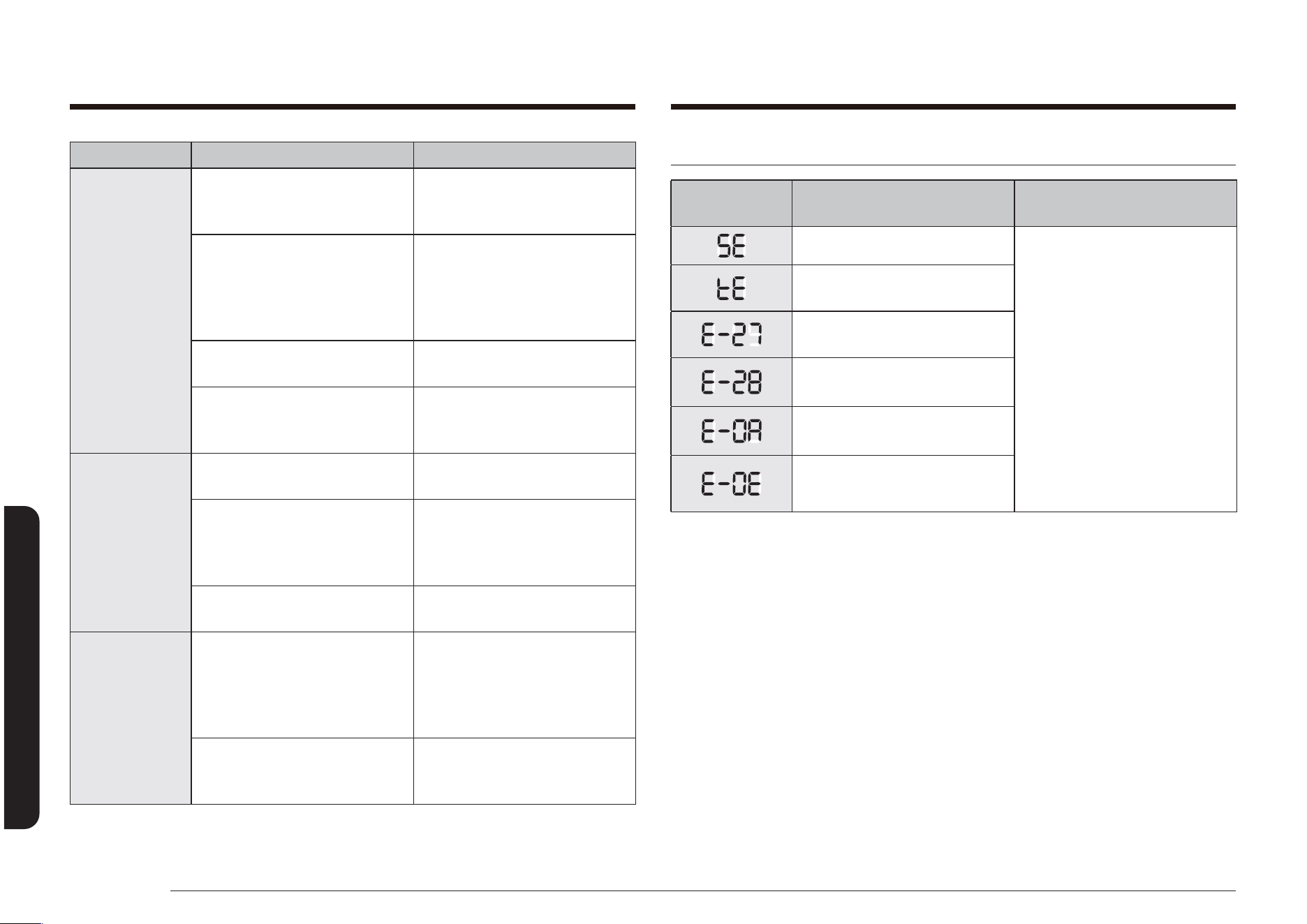
80 Español
Solución de problemas
Solución de problemas
Solución de problemas y códigos de información
SÍMBOLO DEL
CÓDIGO
SIGNIFICADO SOLUCIÓN
Tecla en cortocircuito. Presione la tecla OFF/CLEAR
(APAGAR/BORRAR) y reinicie
el horno.
Si el problema persiste,
desconecte toda alimentación
eléctrica a la estufa durante
por lo menos 30 segundos
y luego reconecte la
alimentación eléctrica.
Si esto no soluciona el
problema, llame al servicio
de reparaciones. Consulte las
instrucciones debajo de esta
tabla.
Verique las senales del PBA
tactil.
Problema de sensor del horno
abierto.
Problema de sensor del horno
en cortocircuitos.
Recalentamiento del horno.
Error de la traba de la puerta.
Para códigos no indicados anteriormente, o si la solución sugerida no repara el
problema, llame al teléfono 1-800-SAMSUNG (726-7864).
PROBLEMA CAUSA POSIBLE SOLUCIÓN
El cajón de
calentamiento
no funciona
(Modelo
NX58*565***).
Los controles no se han
congurado correctamente.
Restablezca los controles
según se describe en las
paginas 58.
Se está utilizando la función
de Auto-limpieza o Shabat.
El cajón de calentamiento no
funcionará durante ninguna
de estas operaciones. Vuelva
a intentarlo después de que la
función nalice o se cancele.
Los controles del horno se
han bloqueado.
Desbloquee los controles y
vuelva a intentarlo.
Hay un fusible quemado o un
disyuntor disparado.
Reemplace el fusible quemado
o reinicie el disyuntor que se
disparó.
Condensación
excesiva en
el cajón de
calentamiento
(Modelo
NX58*565**
*).
La regulación de temperatura
es demasiado alta.
Consulte la página 58.
Los alimentos que se están
calentando no están cubiertos
con una tapa o papel de
aluminio.
Cubra los alimentos con una
tapa o papel de aluminio.
Está intentando calentar
líquidos.
No se deben calentar líquidos
en el cajón. Retire los líquidos.
El cajón de
calentamiento
o el cajón de
almacenamiento
no se desliza
suavemente o se
traba.
El cajón no está
correctamente alineado con
los rieles de la guía giratoria
de extensión completa o las
guías de nailon del cajón.
Retire y vuelva a colocar el
cajón. (Consulte las páginas
69 y 70.)
El contenido del cajón es
demasiado pesado.
Reduzca el peso o
redistribuya los contenidos en
el cajón.

Español 81
Garantía
Durante el periodo de garantía aplicable, el producto se reparará o se reemplazará, o se
devolverá el importe de compra, a la entera discreción de SAMSUNG. SAMSUNG podrá usar
piezas nuevas o reacondicionadas para la reparación del producto, o reemplazar el producto
por un producto nuevo o reacondicionado. La vigencia de la garantía de las piezas y los
productos reemplazados será por el período restante de la garantía original del producto
o por un período de noventa (90) días, el que sea el más largo. Todas las piezas y los
productos reemplazados son propiedad de SAMSUNG y deben ser devueltos a SAMSUNG.
La presente garantía limitada cubre defectos de fabricación de los materiales o la mano
de obra que ocurran durante el uso normal y doméstico de este producto y no cubrirá
lo siguiente: daños que ocurran durante el envío, entrega e instalación y usos para
los cuales el presente producto no fue destinado; daños causados por modicación o
alteración no autorizada del producto; producto cuyos números de serie originales de
fábrica fueron eliminados, desgurados, alterados en algún modo o que no se puedan
determinar fácilmente; daños cosméticos incluyendo rayones, hendiduras, abolladuras y
otros daños al acabado del producto; daño causado por abuso o mal uso, plagas, accidente,
incendio, inundación u otros casos fortuitos o de fuerza mayor; daño causado por el uso
de equipo, utilidades, servicios, piezas, suministros, accesorios, aplicaciones, instalaciones,
reparaciones, cableado externo o conectores no provistos ni autorizados por SAMSUNG;
daño causado por línea eléctrica o voltaje incorrecto, uctuaciones y sobretensión; daño
causado por no operar y mantener el producto de acuerdo con las instrucciones; instrucción
a domicilio acerca de cómo usar el producto; y servicio técnico para corregir una instalación
que no cumpla con los códigos eléctricos o de plomería o corrección de cableado eléctrico o
tuberías (es decir, cableado doméstico, fusibles o mangueras de entrada de agua).
Esta garantía limitada tampoco cubre los daños a la cubierta de vidrio causados por (i) el
uso de productos de limpieza distintos de los productos y almohadillas recomendadas o (ii)
derrames endurecidos de sustancias azucaradas o plásticos fundidos que no se hubiesen
limpiado de acuerdo con las instrucciones incluidas en la guía de uso y cuidados.
El costo de reparación o reemplazo bajo estas circunstancias excluidas será responsabilidad
del cliente.
Las visitas de un proveedor de servicio técnico autorizado para explicar funciones,
mantenimiento o instalación del producto no se cubren bajo esta garantía limitada.
Comuníquese con Samsung al número que gura abajo para obtener ayuda con cualquiera
de estos problemas.
Garantía limitada (Estados Unidos)
NO DESECHE.
ESTUFA DE GAS SAMSUNG
GARANTÍA LIMITADA AL COMPRADOR CONSUMIDOR ORIGINAL CON PRUEBA DE COMPRA
El presente producto de la marca SAMSUNG, tal como lo provee y distribuye SAMSUNG
ELECTRONICS AMERICA, INC. (SAMSUNG) y lo entrega como nuevo, en su caja de cartón
original al comprador consumidor original, está garantizado por SAMSUNG contra defectos
de fabricación de los materiales o la mano de obra durante el período limitado de la
garantía, a partir de la fecha original de compra, de:
Un (1) año para piezas y mano de obra
La presente garantía limitada es válida únicamente para productos comprados y usados
en Estados Unidos que fueron instalados, operados y mantenidos de acuerdo con las
instrucciones adjuntas o provistas con el producto. Para recibir el servicio técnico en
garantía, el comprador debe comunicarse con SAMSUNG en la dirección o el teléfono
que guran más abajo con el n de que se determine el problema y los procedimientos
del servicio. El servicio técnico de la garantía solo puede ser prestado por un centro de
servicio técnico autorizado de SAMSUNG. Para recibir el servicio técnico en garantía debe
presentarse la factura original de compra fechada cuando así lo solicite SAMSUNG o el
Centro de Servicio autorizado Samsung como prueba de compra.
Samsung brindará servicio técnico a domicilio dentro del territorio contiguo de Estados
Unidos durante el período de garantía sin cargo, sujeto a la disponibilidad de los centros de
servicio autorizados por SAMSUNG dentro de la zona geográca del cliente. Si el servicio
técnico a domicilio no está disponible, SAMSUNG puede, a su elección, optar por transportar
el producto hasta y desde un centro de servicio técnico autorizado. Si el producto está
ubicado en una zona en la que no se encuentra disponible ningún centro de servicio
autorizado por SAMSUNG, usted podrá ser responsable del cargo por transporte o se le
podrá requerir que transporte el producto a un centro de servicio autorizado por SAMSUNG
para recibir asistencia técnica.
Para recibir el servicio técnico a domicilio, el producto no debe presentar obstrucciones y
debe ser accesible para el agente del servicio técnico.

82 Español
Garantía
Garantía
Registro
Registre su producto en línea en www.samsung.com/register.
Preguntas
Si tiene preguntas sobre funciones, operación/rendimiento, piezas, accesorios o servicio, llame
al 1-800-SAMSUNG (726-7864) o visite nuestro sitio Web en www.samsung.com/us/support.
Modelo # Serie #
Adjunte su recibo (o una copia) a este manual. Es posible que lo necesite, junto con su
modelo y número de serie, cuando llame para obtener asistencia.
EXCLUSIÓN DE GARANTÍAS IMPLÍCITAS
LAS GARANTÍAS IMPLÍCITAS, INCLUYENDO GARANTÍAS IMPLÍCITAS DE COMERCIABILIDAD
O APTITUD PARA UN PROPÓSITO EN PARTICULAR, ESTÁN LIMITADAS A UN AÑO O AL
PERIODO MÁS CORTO PERMITIDO POR LA LEY. Algunos estados no permiten limitaciones
en cuanto al periodo de vigencia de una garantía implícita, de tal forma que las limitaciones
o exclusiones mencionadas tal vez no se apliquen a usted en particular. Esta garantía le
otorga derechos especícos, e incluso usted también puede tener otros derechos que varían
de un estado a otro.
LIMITACIÓN DE RECURSOS
EL ÚNICO Y EXCLUSIVO RECURSO ES LA REPARACIÓN DEL PRODUCTO, EL REEMPLAZO DEL
PRODUCTO O LA DEVOLUCIÓN DEL IMPORTE DE COMPRA, A DISCRECIÓN DE SAMSUNG,
CONFORME A ESTA GARANTÍA LIMITADA. SAMSUNG NO SERÁ RESPONSABLE POR DAÑOS
ESPECIALES, IMPREVISTOS O DERIVADOS, INCLUYENDO ENTRE OTROS, TIEMPO FUERA
DEL TRABAJO, HOTELES Y/O COMIDAS EN RESTAURANTES, GASTOS DE REMODELACIÓN,
PÉRDIDAS DE INGRESOS O GANANCIAS, INCAPACIDAD DE GENERAR AHORROS U OTROS
BENEFICIOS INDEPENDIENTEMENTE DE LA TEORÍA LEGAL EN LA QUE SE BASE EL
RECLAMO, E INCLUSO SI SAMSUNG HA SIDO ADVERTIDA DE LA POSIBILIDAD DE DICHOS
DAÑOS. Algunos estados no permiten la exclusión o la limitación de daños imprevistos o
derivados, por lo que las limitaciones o exclusiones mencionadas tal vez no se apliquen a
usted en particular. Esta garantía le otorga derechos especícos, e incluso usted también
puede tener otros derechos que varían de un estado a otro.
SAMSUNG no garantiza el funcionamiento ininterrumpido o sin errores del producto.
Ningún aval o garantía otorgados por otra persona, compañía o corporación con respecto al
presente producto revestirá carácter vinculante para SAMSUNG.
Para obtener el servicio de garantía, comuníquese con SAMSUNG en:
Samsung Electronics America, Inc.
85 Challenger Road
Ridgeeld Park, NJ 07660
1-800-SAMSUNG (726-7864) www.samsung.com/us/support

Español 83
Garantía
SAMSUNG reparará o reemplazará el producto a nuestra discreción y sin cargo tal como
se establece en la presente garantía, con piezas o productos nuevos o reacondicionados si
se comprueba que es defectuoso durante el período limitado de la garantía especicado
anteriormente. Todas las piezas y los productos reemplazados pasan a ser propiedad de
SAMSUNG y deben ser devueltos a SAMSUNG. Las piezas y los productos reemplazados
asumen la garantía original que resta, o noventa (90) días, el período que sea el más
prolongado.
Esta garantía limitada no cubre casos de corriente, voltaje o alimentación eléctrica
incorrectos, bombillas de luz, fusibles y cableado en la casa, el costo de las llamadas al
servicio técnico para solicitar instrucciones, ni la corrección de errores de instalación.
Tampoco están cubiertos los daños a la cubierta causados por el uso de productos y
elementos de limpieza distintos de los productos y esponjas recomendadas, y daños a la
cubierta causados por derrames endurecidos de sustancias azucaradas o plásticos fundidos
que no hubiesen sido limpiados de acuerdo con las instrucciones incluidas en la guía de
uso y cuidados. SAMSUNG no garantiza el funcionamiento ininterrumpido o sin errores del
producto.
SALVO LO ESTABLECIDO EN ESTE DOCUMENTO, NO EXISTEN GARANTÍAS NI CONDICIONES
RESPECTO DE ESTE PRODUCTO NI EXPRESAS NI TÁCITAS Y SAMSUNG DESCONOCE Y
RECHAZA TODA GARANTÍA Y CONDICIÓN INCLUIDA, AUNQUE NO TAXATIVAMENTE
ENUMERADA, TODA GARANTÍA Y CONDICIÓN TÁCITA DE COMERCIABILIDAD, INFRACCIÓN O
APTITUD PARA UN PROPÓSITO ESPECIAL. NINGUNA OTRA GARANTÍA OTORGADA POR
PERSONA, COMPAÑÍA O CORPORACIÓN ALGUNA CON RESPECTO AL PRESENTE PRODUCTO
REVESTIRÁ
CARÁCTER VINCULANTE PARA SAMSUNG. SAMSUNG NO SERÁ RESPONSABLE POR PÉRDIDA
DE INGRESOS O LUCRO CESANTE, IMPOSIBILIDAD DE GENERAR AHORROS U OBTENER
OTROS BENEFICIOS, O CUALQUIER DAÑO DERIVADO DE CIRCUNSTANCIAS ESPECIALES,
DAÑO IMPREVISTO O DERIVADO CAUSADO POR EL USO, USO INCORRECTO, O INCAPACIDAD
PARA USAR EL PRESENTE PRODUCTO,
Garantía (CANADÁ)
NO DESECHE.
ESTUFA DE GAS SAMSUNG
GARANTÍA LIMITADA PARA EL COMPRADOR ORIGINAL
El presente producto de la marca SAMSUNG, tal como lo provee y distribuye SAMSUNG
ELECTRONICS CANADA INC. (SAMSUNG) y lo entrega como nuevo, en su empaque de cartón
original al comprador consumidor original, está garantizado por SAMSUNG contra defectos
de fabricación de los materiales y la mano de obra durante el período de la garantía
limitada de:
Un (1) año para piezas y mano de obra
La presente garantía limitada comienza en la fecha original de compra y es válida
únicamente para productos comprados y usados en Canadá. Para recibir el servicio
técnico de la garantía, el comprador debe comunicarse con SAMSUNG con el n de que se
determine el problema y los procedimientos del servicio. El servicio técnico de la garantía
solo puede ser prestado por un centro de servicio técnico autorizado de SAMSUNG y
cualquier servicio no autorizado anulará esta garantía. Se debe presentar la factura de
compra original como prueba de compra a SAMSUNG o al servicio técnico autorizado de
SAMSUNG. Samsung brindará servicio técnico a domicilio sin cargo durante el período de
garantía de un (1) año, sujeto a disponibilidad, dentro del territorio contiguo de Canadá.
El servicio a domicilio no está disponible en todas las zonas. Como condición para que se
preste este servicio a domicilio, el producto debe encontrarse libre de obstrucciones y
accesible para el agente de servicio. Si el servicio no está disponible, Samsung podrá optar
por brindar el servicio de transporte del producto de ida y vuelta al centro de servicio.
84 Español
Garantía
Garantía
Registro
Registre su producto en línea en www.samsung.com/register.
Preguntas
Si tiene preguntas sobre funciones, operación/rendimiento, piezas, accesorios o servicio, llame
al 1-800-SAMSUNG (726-7864) o visite nuestro sitio Web en www.samsung.com/ca/support
(English) o www.samsung.com/ca_fr/support (French).
Modelo # Serie #
Adjunte su recibo (o una copia) a este manual. Es posible que lo necesite, junto con su
modelo y número de serie, cuando llame para obtener asistencia.
INDEPENDIENTEMENTE DE LA TEORÍA LEGAL EN QUE SE FUNDE EL RECLAMO Y AUN
CUANDO SE LE HAYA NOTIFICADO A SAMSUNG DE LA POSIBILIDAD DE TALES DAÑOS.
NINGÚN RESARCIMIENTO DE NINGUNA ÍNDOLE CONTRA SAMSUNG SUPERARÁ EL MONTO
DEL PRECIO DE COMPRA DEL PRODUCTO VENDIDO POR SAMSUNG Y CAUSANTE DEL
PRESUNTO DAÑO. SIN LIMITAR LO PRECEDENTE, EL COMPRADOR ASUME TODO EL RIESGO
Y LA RESPONSABILIDAD POR PÉRDIDA, DAÑO O LESIÓN AL COMPRADOR Y A LOS BIENES
DEL COMPRADOR Y A TERCEROS Y A SUS BIENES DERIVADOS DEL USO, USO INCORRECTO O
INCAPACIDAD PARA USAR EL PRESENTE PRODUCTO. LA PRESENTE GARANTÍA LIMITADA NO
SE EXTENDERÁ A NINGUNA PERSONA DISTINTA DEL COMPRADOR ORIGINAL DEL PRESENTE
PRODUCTO, ES INTRANSFERIBLE Y ESTABLECE SU EXCLUSIVA REPARACIÓN.
Algunos territorios o provincias pueden permitir, o no, las limitaciones en cuanto al plazo
de una garantía implícita, o la exclusión o limitación de daños imprevistos o derivados,
por lo tanto las limitaciones o exclusiones antedichas pueden no aplicarse en su caso. Esta
garantía le otorga derechos legales especícos, y además puede tener otros derechos que
varían según el estado o la provincia en el que se encuentre. Las piezas sustituibles por
el usuario se pueden enviar al cliente para la reparación de la unidad. Si es necesario, se
puede enviar a un técnico para que efectúe el servicio.
Para recibir un servicio técnico de garantía, comuníquese con SAMSUNG a:
Samsung Electronics Canada Inc.
2050 Derry Road West, Mississauga, Ontario L5N 0B9 Canada
1-800-SAMSUNG (726-7864) y www.samsung.com/ca/support (English),
www.samsung.com/ca_fr/support (French)
Tenga en cuenta que la garantía de Samsung NO cubre las llamadas de servicio para explicar el funcionamiento del producto, corregir una instalación inadecuada o realizar
tareas de limpieza o mantenimiento.
¿TIENE PREGUNTAS O COMENTARIOS?
PAÍS LLAME AL O VISÍTENOS EN LÍNEA EN
U.S.A
Consumer Electronics
1-800-SAMSUNG (726-7864) www.samsung.com/us/support
CANADA 1-800-SAMSUNG (726-7864)
www.samsung.com/ca/support (English)
www.samsung.com/ca_fr/support (French)
DG68-00526A-15
Escanee el código QR* o visite
www.samsung.com/spsn
para ver nuestros útiles videos
instructivos y programas en vivo
* Requiere un lector instalado en su
teléfono inteligente
Cuisinière à gaz non
encastrable
Manuel d'utilisation
NX58*565***/NX58*560***/NX58*751***
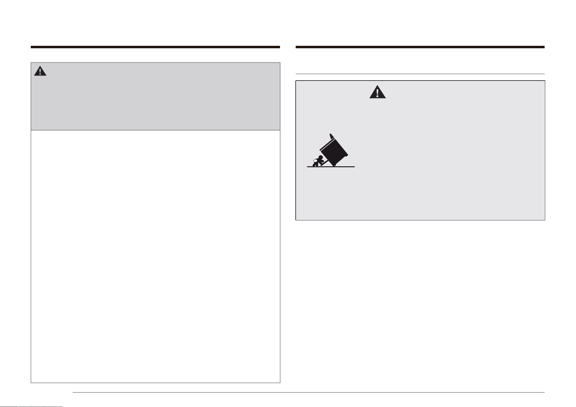
2 Français
DISPOSITIF ANTIBASCULEMENT
AVERTISSEMENT
Risque de basculement
• Un enfant ou un adulte pourrait faire basculer la
cuisinière et être tué.
• Installez le dispositif anti-basculement sur la
cuisinière et/ou structure conformément aux
instructions d’installation de ce manuel.
• Engagez la cuisinière avec le dispositif anti-
basculement installé.
• Engagez à nouveau le dispositif anti-basculement si
la cuisinière est déplacée.
• Le défaut de suivre les présentes directives pourrait
entraîner la mort ou des brûlures graves pour des
enfants et des adultes.
AVERTISSEMENT
Si vous ne respectez pas scrupuleusement les informations
contenues dans ce manuel, vous risquez de provoquer un
incendie ou un choc électrique et, par conséquent, des dégâts
matériels, blessures ou accidents mortels.
• N'entreposez et n'utilisez pas d'essence ou d'autres
vapeurs et liquides inammables à proximité de cet
appareil ou de tout autre.
• N'entreposez, ne placez ni n'utilisez jamais des matériaux
inammables ou combustibles tels que du charbon, du
papier, du plastique, des maniques, des tissus, des rideaux,
de l'essence ou d'autres vapeurs ou liquides inammables
à proximité de la cuisinière.
• DANS LE CAS OÙ VOUS SENTEZ UNE ODEUR DE GAZ :
- N’allumez AUCUN appareil.
- NE touchez AUCUN commutateur électrique.
- N'utilisez PAS de téléphone dans votre immeuble.
- Appelez immédiatement votre fournisseur de gaz à
partir du téléphone d'un voisin. Suivez les instructions
de votre fournisseur de gaz.
- Si vous n'arrivez pas à joindre votre fournisseur de
gaz, appelez les pompiers
• L'installation et l'entretien doivent être effectués par un
installateur qualié, une agence de maintenance ou votre
fournisseur de gaz.
Français 3
CARACTÉRISTIQUES DE VOTRE NOUVELLE
CUISINIÈRE
Plus de commodité. Cuisson de meilleure qualité. Entretien
facile. Votre nouvelle cuisinière à gaz a été conçue pour vous
offrir tous ces avantages et plus encore.
Plus d'espace
Dotée d'une capacité de 5,8 pieds cubes, votre nouvelle
cuisinière dispose d'un espace bien plus important que toutes
les marques concurrentes présentes sur les marchés américain
et canadien. Il vous est désormais plus facile de cuisiner
pendant les fêtes ou pour le plaisir.
Table de cuisson à 5 brûleurs
Des brûleurs haute puissance, des brûleurs de mijotage ainsi
qu'un brûleur ovale central fournissent une chaleur de cuisson
réglable pour une grande variété d'ustensiles.
Le brûleur ovale central fournit une chaleur uniforme sur une
grande surface ; il est donc idéal pour la cuisson au gril.
An d'éviter le basculement de la cuisinière, xez-la
correctement au sol à l'aide d'un support anti-basculement
adapté. (Reportez-vous au chapitre Installation
du dispositif anti-basculement dans les consignes
d'installation.) Vériez la bonne installation en basculant
la cuisinière avec précaution en avant. Veillez à ce que le
dispositif anti-basculement soit en place an d'empêcher la
cuisinière de basculer.
Si la cuisinière est, pour une quelconque raison, retirée du
mur, assurez-vous que le dispositif anti-basculement est
convenablement remonté une fois que la cuisinière est
remise en place.
Respectez les consignes d'installations décrites dans le
manuel d'installation. Le non-respect de ces consignes peut
entraîner des accidents mortels, blessures et/ou dégâts
matériels.

4 Français
Sommaire
Sommaire
Ventilation du four 37
Éclairage du four 37
Faire cuire de la pâte crue 38
Cuisson et rôtissage par convection 39
Cuisson minutée 42
Cuisson minutée différée 44
Cuisson au gril 46
Maintien au chaud 48
Utilisation de la fonction Cuisson facile 48
Mode friture par application d'air (MODÈLE NX58*751***) 50
Cuisson personnalisée 52
Fonctionb Shabbat 54
Fonctions complémentaires 56
Utilisation du tiroir chauffe-plat 58
À propos du tiroir chauffe-plat
(modèle NX58*565*** uniquement) 58
Activation ou désactivation du tiroir chauffe-plat 58
Entretien de votre appareil 59
Entretien et nettoyage du four 59
Entretien et nettoyage de la plaque de cuisson 63
Remplacement de l’ampoule du four 67
Retrait et remise en place de la porte du four 67
Enlever et remettre le tiroir chauffe-plat
(modèle NX58*565***) 69
Enlever et remettre le tiroir de rangement
(modèle NX58*560***, NX58*751***) 70
Auto-nettoyage du four 71
Dépannage 74
Dépannage 74
Dépannage et codes d'erreur 80
Garantie (États-Unis) 81
Garantie (CANADA) 83
Sommaire
Consignes de sécurité importantes 5
Symboles de sécurité 5
California Proposition 65 Avertissement 5
Précautions importantes relatives à la sécurité 6
Avertissements concernant le gaz 10
Dans le Commonwealth du Massachusetts 12
Mises en garde relatives aux risques électriques 12
Consignes de mise à la terre 13
Avertissements relatifs à l'installation 14
Avertissements concernant les brûleurs de surface 16
Avertissements concernant le four 19
Avertissements concernant le tiroir chauffe-plat électrique ou le tiroir de rangement inférieur 21
Avertissements concernant le four auto-nettoyant 21
Cuisson appropriée de la viande et de la volaille 22
Présentation de votre nouvelle cuisinière 23
Présentation 23
Table de cuisson 26
Allumer un brûleur 26
Allumer manuellement un brûleur de surface à gaz 26
Sélection de la taille de la amme 26
Brûleurs de surface à gaz et boutons de commandes 26
Utilisation des récipients 27
Grille du brûleur central 28
Wok grate (wok grille) (NX58*565*** uniquement) 28
Utilisation du gril 29
Utilisation du four 30
Tableaux de commande et afchages du four 30
Réglage de l'horloge 33
Activation/désactivation de la minuterie 34
Positionnement des grilles du four 35
Comment utiliser la grille coulissante
(NX58*565*** uniquement) 36
Français 5
Consignes de sécurité importantes
CONSERVEZ PRÉCIEUSEMENT CES CONSIGNES
Interdit.
NE PAS démonter.
NE PAS toucher.
Suivez scrupuleusement les consignes.
Débranchez le cordon d'alimentation de la prise murale.
Assurez-vous que la cuisinière est branchée sur une
prise murale reliée à la terre an d'éviter tout risque
d'électrocution. L'utilisation d'une prise dotée d'un
interrupteur différentiel est fortement recommandée.
Contactez le service d'assistance technique. Reportez-vous
à la page 85.
Remarque
Les symboles d'avertissement sont là pour éviter que vous ou
d'autres personnes ne se blessent. Veillez à bien en respecter les
consignes. Veuillez ne pas jeter ce manuel. Conservez ce manuel
dans un endroit sûr an de pouvoir le consulter ultérieurement.
CALIFORNIA PROPOSITION 65 AVERTISSEMENT
AVERTISSEMENT
Cancer et Troubles de l’appareil reproducteur – www.P65Warnings.ca.gov.
Consignes de sécurité importantes
LISEZ TOUTES LES CONSIGNES DE SÉCURITÉ AVANT D'UTILISER
L'APPAREIL
Tous les appareils électriques et à gaz comportant des pièces
mobiles présentent un danger. Veuillez lire les consignes de
sécurité importantes pour cet appareil dans ce manuel. Ces
instructions doivent être respectées an de minimiser les
risques de blessures graves, voire mortelles ou de dégâts
matériels.
Conservez ce manuel/Veuillez ne pas le jeter
SYMBOLES DE SÉCURITÉ
Signication des icônes et des symboles utilisés dans ce
manuel :
AVERTISSEMENT
Il existe un risque de blessures corporelles graves ou mortelles.
ATTENTION
Il existe un risque de blessures corporelles ou de dégâts
matériels.
ATTENTION
An de réduire les risques d'incendie, d'explosion, d'électrocution
ou de blessures lors de l'utilisation de votre cuisinière à gaz, vous
devez respecter ces règles de sécurité de base :

6 Français
Consignes de sécurité importantes
Consignes de sécurité importantes
CONSERVEZ PRÉCIEUSEMENT CES CONSIGNES
Vous devez connaître l'emplacement de la vanne de fermeture de
gaz et savoir comment celle-ci se ferme, le cas échéant.
Enlevez ou détruisez correctement l'emballage une fois l'appareil
déballé.
Électrique/Mécanique
Débranchez la cuisinière ou mettez-la hors tension avant de
procéder à la réparation.
Ne modiez pas les boutons de commande. Les grilles et plaques (si
fournies) sont lourdes. Elles présentent un danger si elles tombent.
La partie intérieure de la grille en deux pièces (si fournie) du four
pourrait tomber accidentellement si elle n'a pas été assemblée
correctement. Positionnez la grille intérieure correctement sur la
grille extérieure.
Positionnez toujours les grilles du four à la même hauteur de
chaque côté du four. Le non-respect de cette consigne peut
entraîner une chute des aliments et par conséquent un risque de
brûlures.
PRÉCAUTIONS IMPORTANTES RELATIVES À LA SÉCURITÉ
AVERTISSEMENT
Suivez toutes les consignes de bases lorsque vous installez
et utilisez votre cuisinière an d'éviter tout risque d'incendie,
d'électrocution, de blessures graves ou mortelles, incluant :
Installation et entretien
Cette cuisinière doit être correctement placée et installée conformément
aux consignes d'installation avant de pouvoir être utilisée.
Une installation par un professionnel est fortement recommandée.
En raison de sa taille et de son poids, la cuisinière doit être
transportée et installée par au moins deux personnes.
Toutes les cuisinières sont susceptibles de basculer et de provoquer
des blessures graves. Installez le dispositif anti-basculement fourni
avec cette cuisinière en suivant les instructions décrites dans les
consignes d'installation.
Ne réparez ni ne remplacez jamais cet appareil vous-même, sauf si
le présent manuel vous y autorise. L'entretien de cet appareil doit
impérativement être assuré par un technicien qualié.

Français 7
Consignes de sécurité importantes
CONSERVEZ PRÉCIEUSEMENT CES CONSIGNES
Apprenez aux enfants à ne pas toucher aux commandes ou aux
autres éléments de la cuisinière et à ne pas jouer avec.
Nous vous conseillons d'utiliser la fonction de verrouillage des
commandes/de la porte an de réduire tout risque d'utilisation
incorrecte par des enfants.
Avant de mettre votre cuisinière au rebut, débranchez le cordon
d'alimentation. Retirez la porte an d'éviter que des enfants ou des
animaux ne se fassent piéger à l'intérieur de l'appareil.
Danger pour les enfants
N'entreprosez pas d'objets susceptibles d'éveiller l'intérêt des
enfants sur la table de cuisson ou sur le dosseret de la cuisinière.
Les enfants risquent, en grimpant sur la cuisinière, de se blesser
gravement, voire mortellement.
La grille intérieure de la grille en deux pièces peut tomber si elle
n'a pas été assemblée correctement. Positionnez la grille intérieure
correctement sur la grille extérieure. Insérez toujours la grille ou
l'ensemble de la grille en deux pièces (si fournie) sur la même
hauteur de chaque côté du four.
Gardez tous les éléments d'emballage hors de la portée des
enfants. Ceux-ci risqueraient de les utiliser pour jouer. Si les sacs en
plastique ne sont pas jetés, cela peut entraîner une asphyxie.
Ne laissez jamais un enfant sans surveillance dans la pièce où est
installée la cuisinière. Ne les autorisez jamais à monter sur une
quelconque partie de la cuisinière.
Ne laissez pas de petits enfants toucher la cuisinière.
Les grilles et la plaque (si fournie) de la table de cuisson sont
lourdes et présentent un risque de blessures si elles tombent sur
le pied. Apprenez aux enfants à ne pas jouer avec les grilles ou la
plaque.
8 Français
Consignes de sécurité importantes
Consignes de sécurité importantes
CONSERVEZ PRÉCIEUSEMENT CES CONSIGNES
Cette cuisinière ne doit jamais être utilisée à d'autres ns que
la cuisson. Le non-respect de cette consigne peut entraîner une
intoxication au monoxyde de carbone et/ou une surchauffe du four.
Évitez de porter des vêtements amples et des accessoires pendants
lorsque vous utilisez l'appareil.
N'ENTREPOSEZ ET N'UTILISEZ PAS de matériaux combustibles,
d'essence ou d'autres vapeurs et liquides inammables à proximité
de cet appareil. Voir « DANS LE CAS OÙ VOUS SENTEZ UNE ODEUR
DE GAZ » dans le chapitre des avertissements concernant le gaz :
Lors du nettoyage de la table de cuisson, ne versez pas d'eau sur
celle-ci. L'eau pourrait couler dans les systèmes d'alimentation en
gaz et dans les circuits électriques de la cuisinière entraînant un
risque d'électrocution ou un niveau élevé de monoxyde de carbone
dû à la corrosion des orices des combustibles.
N'utilisez pas d'eau pour éteindre les ammes de friture. L'eau peut
entraîner une explosion d'une amme de friture, ce qui pourrait
entraîner et propager un incendie puis entraîner des dommages
corporels. Eteignez la source de chaleur et étouffez les ammes
à l'aide d'un couvercle hermétique ou en utilisant un extincteur
multifonction à poudre ou à mousse.
Ne laissez jamais la table de cuisson sans surveillance lorsqu'un
brûleur fonctionne à puissance élevée. En cas de débordement,
les particules graisseuses provenant des aliments risquent de
s'enammer.
N'utilisez pas de amme pour vérier s'il y a des fuites de gaz.
Utilisez de l'eau savonneuse autour de l'endroit à vérier.
Incendie
Ne touchez pas les brûleurs du four, les brûleurs du tiroir ou
les surfaces internes du four pendant ou immédiatement après
la cuisson. Les surfaces de cuisson, les grilles, les brûleurs et
les chapeaux de la table de cuisson ainsi que les parois du four
peuvent être chauds même s’ils n’apparaissent pas rouges. Les
surfaces internes du four deviennent sufsamment chaudes
pour provoquer des brûlures. Pendant et après l’utilisation, ne
touchez pas les brûleurs du four, les brûleurs du tiroir et les
surfaces internes du four et ne laissez aucun vêtement ou produit
inammable entrer en contact avec ces derniers tant qu’ils n’ont
pas refroidis.
Les maniques ne doivent pas entrer en contact avec les éléments
chauffants. N'utilisez pas de serviette ou tout autre torchon
volumineux comme manique.
N'utilisez pas votre cuisinière pour chauffer des aliments contenus
dans des récipients fermés ou pour sécher des objets humides.
N'obstruez pas les conduits de ventilation du four. Nettoyez
fréquemment les orices de ventilation pour éviter qu'ils ne
s'encrassent. Voir page 37. Pendant la cuisson au four, il se peut
que vous entendiez un léger bruit de crépitement. Ce bruit peut
apparaître pendant le cycle normal de cuisson au four lorsque la
amme du brûleur du four s'éteint.

Français 9
Consignes de sécurité importantes
CONSERVEZ PRÉCIEUSEMENT CES CONSIGNES
Vapeurs
Soyez prudent lorsque vous ouvrez la porte du four. Laissez l'air
chaud ou la vapeur s'échapper avant de retirer les aliments du four
chaud ou de les remettre.
Utilisez uniquement des maniques sèches. L'utilisation de maniques
humides ou mouillées sur des surfaces chaudes peut entraîner des
brûlures par la vapeur.
Avertissements concernant les brûleurs de surface
• La tête des brûleurs peut être obstruée par de la nourriture
ou de la poussière. Nettoyez la tête si elle semble obstruée.
Si vous nettoyez la tête à l’eau, ne la reassemblez qu’une fois
qu’elle est parfaitement sèche Une tête mouillée peut empêcher
les brûleurs de s’allumer.
• Pour nettoyer la table de cuisson, ne versez pas d'eau sur
celle-ci. L'eau peut s'introduire dans la cuisinière et les pièces
internes risquent de rouiller.
Ne placez aucun appareil portable ou tout objet différent d'un
ustensile de cuisine sur la surface de cuisson. Si la surface de
cuisson est chaude, cela peut provoquer un incendie ou des dégâts
matériels.
N'essayez pas d'utiliser cette cuisinière si elle est endommagée,
en dysfonctionnement ou s'il y a des pièces manquantes ou
défectueuses.
Ne placez jamais d'objets en plastique, en papier ou dans une autre
matière susceptible de fondre ou de brûler à proximité des orices
de ventilation ou des brûleurs de surface.
Si le mode d'auto-nettoyage ne fonctionne pas, éteignez le four et
débranchez-le de la prise d'alimentation. Reportez-vous aux pages
81 et 82 pour contacter un technicien de maintenance qualié.
Pendant la cuisson au four, il se peut que vous entendiez un léger
bruit de crépitement.
10 Français
Consignes de sécurité importantes
Consignes de sécurité importantes
CONSERVEZ PRÉCIEUSEMENT CES CONSIGNES
• Après avoir allumé un brûleur de surface, vériez qu'il
s'enamme. Ajustez le niveau de la amme en tournant le
bouton du brûleur.
• Lorsque vous réglez un brûleur sur mijotage, ne tournez pas le
bouton rapidement. Observez la amme pour vérier qu'elle
reste allumée.
AVERTISSEMENTS CONCERNANT LE GAZ
AVERTISSEMENT
Si vous ne respectez pas scrupuleusement les informations
contenues dans ce manuel, vous risquez de provoquer un
incendie ou une explosion et, par conséquent, des accidents
mortels, blessures ou dégâts matériels.
1. Fermez la vanne et n'utilisez pas la cuisinière.
2. N'allumez PAS d'allumette, de bougie ou de cigarette.
3. N'allumez AUCUN appareil au gaz ou électrique.
4. NE touchez AUCUN commutateur électrique et ne branchez
PAS le cordon d'alimentation sur la prise.
5. N'utilisez PAS de téléphone dans votre immeuble.
• Allumez les brûleurs de la table de cuisson uniquement lorsque
leurs chapeaux sont correctement installés. Si les chapeaux des
brûleurs ne sont pas correctement installés, les commandes
peuvent être endommagées et la amme risque d'être
anormalement grande ou dangereuse.
• Si vous faites réchauffer des liquides, l'ébullition peut survenir
à retardement. Pour éviter une ébullition à retardement des
liquides, laissez-les TOUJOURS reposer au moins une vingtaine
de secondes une fois le brûleur éteint, ceci an de permettre à
la température de se stabiliser. En cas d'accident, effectuez les
gestes de PREMIERS SECOURS suivants :
- immergez la zone brûlée dans de l'eau froide pendant au
moins 10 minutes ;
- couvrez avec un pansement sec et propre
- n'appliquez aucune crème, huile ou lotion
• Le 'repère de l’étincelle' situé sur la tête des brûleurs doubles
doit être placé à côté de l’électrode lorsqu’il est assemblé an
d’éviter une amme anormale.

Français 11
Consignes de sécurité importantes
CONSERVEZ PRÉCIEUSEMENT CES CONSIGNES
N'installez pas cet appareil à un endroit où il sera exposé à de forts
courants d'air.
L'installation et l'entretien doivent être effectués par un installateur
qualié, une agence de maintenance ou votre fournisseur de gaz.
Demandez à l'installateur de vous montrer l'emplacement de la
vanne de coupure du gaz et comment celle-ci se ferme.
Utilisez toujours des connecteurs exibles NEUFS lorsque vous
installez un appareil à gaz. N'utilisez jamais de connecteurs
exibles anciens. L'utilisation des connecteurs exibles anciens
peut entraîner des fuites de gaz et provoquer des blessures.
6. Evacuez la pièce, l'immeuble ou le quartier de tous les
occupants.
7. Appelez immédiatement votre fournisseur de gaz à partir
du téléphone d'un voisin. Suivez les instructions de votre
fournisseur de gaz.
8. Si vous n'arrivez pas à joindre votre fournisseur de gaz,
appelez les pompiers.
Lisez entièrement et attentivement les
instructions.
L'installation de cette cuisinière doit être conforme aux codes
locaux ou, en absence de codes locaux, au National Fuel Gas Code
(Code national de gaz combustible), ANSI Z223.1/NFPA.54, dernière
édition. Au Canada, l'installation doit être conforme au Natural
Gas Installation Code (Code d'installation du gaz naturel), CAN/
CGA-B149.1, en vigueur, ou au Propane Installation Code (Code
d'installation du propane), CAN/CGA-B149.2, en vigueur, ainsi
qu'aux codes locaux qui s'appliquent. Cette cuisinière a été certiée
par ETL selon ANSI Z21.1, dernière édition, et par la Canadian Gas
Association (l'Association canadienne du gaz) selon CAN/CGA-1.1,
dernière édition.
12 Français
Consignes de sécurité importantes
Consignes de sécurité importantes
CONSERVEZ PRÉCIEUSEMENT CES CONSIGNES
DANS LE COMMONWEALTH DU MASSACHUSETTS
Cet appareil doit être installé par un plombier certié ou un
monteur d'installations au gaz qualié ou certié par l'État du
Massachusetts.
Lorsque des vannes à bille sont utilisées pour la fermeture du gaz,
elles doivent être munies d'une poignée en T.
Il ne faut pas connecter plusieurs canalisations de gaz exibles en
série.
MISES EN GARDE RELATIVES AUX RISQUES
ÉLECTRIQUES
Veillez à vous conformer aux consignes et recommandations
suivantes concernant l'électricité an d'éviter tout risque
d'accident mortel et de blessure due à une électrocution et/ou
de dégâts matériels dus à un incendie.
1. Branchez l'appareil sur une prise murale
tripolaire reliée à la terre.
2. N'enlevez PAS la prise murale.
3. N'utilisez PAS d'adaptateur.
4. N'utilisez JAMAIS de rallonge.
N'utilisez jamais cet appareil en tant que chauffage intérieur pour
chauffer une pièce. Le non-respect de cette consigne peut entraîner
une intoxication au monoxyde de carbone et une surchauffe du
four.
Veillez à ne jamais obstruer les orices de ventilation du four
(ouvertures d'air). Ils permettent à l'air d'entrer et de sortir ce qui
est nécessaire pour que le four fonctionne correctement avec un
combustible approprié.
Ne vous appuyez pas sur la cuisinière car vous risqueriez de
tourner malencontreusement les boutons de commande.
Ne montez pas sur l'appareil et ne placez pas d'objets (ex. : linge,
couvercle de four, bougies allumées, cigarettes allumées, plats,
produits chimiques, objets métalliques, etc.) dessus.
• Des articles, comme des vêtements, peuvent rester coincés
dans la porte.
• Cela pourrait entraîner un risque d'électrocution, d'incendie, de
défaillance de l'appareil ou de blessures.

Français 13
Consignes de sécurité importantes
CONSERVEZ PRÉCIEUSEMENT CES CONSIGNES
Ne branchez JAMAIS le câble de mise à la terre sur des
canalisations en plastique ou des conduites de gaz ou d'eau
chaude.
NE modiez PAS la prise fournie avec cet appareil.
NE mettez PAS de fusible dans un circuit neutre ou de terre.
CONSIGNES DE MISE À LA TERRE
Mise à la terre de la cuisinière à l'aide d'un branchement du
câble d'alimentation :
Cet appareil doit être relié à la terre. La mise à la terre réduit
le risque d'électrocution, car elle fournit au courant un chemin
de sortie en cas de dysfonctionnement ou de panne. Cette
cuisinière est équipée d'un cordon disposant d'une prise de
mise à la terre. La che doit être branchée sur une prise
secteur posée et mise à la terre conformément à la législation
en vigueur.
Utilisez un circuit électrique dédié de 120 V, 60 Hz, 20 A (CA)
avec fusible pour cet appareil. Il est recommandé d'utiliser un
fusible à retardement ou un disjoncteur à retardement. NE
branchez PAS plus d'un seul appareil sur ce circuit.
Cette cuisinière est fournie avec une prise tripolaire reliée à
la terre. Ce cordon DOIT être branché dans une prise murale
tripolaire mise à la terre et être conforme aux normes
électriques en vigueura. Si vous n'êtes pas sûr que la prise est
correctement mise à la terre, consultez un électricien qualié
an qu'il vérie.
Si les normes permettent l'utilisation d'un câble de mise à la
terre séparé, nous vous recommandons de faire appel à un
électricien qualié an qu'il détermine le chemin approprié
pour ce câble.
L'installation électrique de la cuisinière doit être conforme
aux codes locaux. En dehors des codes locaux, l'installation
électrique doit être conforme à la dernière norme ANSI/
NFPA N°70 – dernière édition (pour les États-Unis) ou au code
électrique canadien CSA C22.1 – dernière édition.
Il relève de la responsabilité du propriétaire de l'appareil de
fournir une installation électrique conforme.
14 Français
Consignes de sécurité importantes
Consignes de sécurité importantes
CONSERVEZ PRÉCIEUSEMENT CES CONSIGNES
AVERTISSEMENT
Ces réglages doivent être effectués par un technicien de
maintenance qualié conformément aux consignes du fabricant
ainsi qu'à tous les codes et exigences requises par l'autorité
compétente. Le non-respect de ces consignes peut entraîner
des blessures graves et/ou des dégâts matériels. L'agence
qualiée effectuant ces travaux assume la responsabilité de la
conversion de gaz.
Ne réparez ni ne remplacez jamais les pièces de la cuisinière
vous-même, sauf si le présent manuel vous y autorise. Toute
autre réparation devra être effectuée par un technicien
qualié.
Cet appareil doit être correctement relié à la terre. Branchez
la cuisinière sur une prise murale de 115 V reliée à la terre
qui doit uniquement être utilisée pour cette cuisinière. Ne
coupez ni ne retirez la (troisième) broche mise à la terre de la
prise. Branchez le cordon d'alimentation fermement à la prise
murale. Si vous n'êtes pas sûr que la prise est reliée à la terre,
il relève de votre responsabilité de fournir une prise tripolaire
correctement installée et reliée à la terre conformément aux
normes locales et nationales.
AVERTISSEMENT
Tout raccordement non conforme de la prise de mise à la terre peut
entraîner un risque d'électrocution. Si vous n'êtes pas sûr que l'appareil
est correctement mis à la terre, vériez-le avec un électricien qualié.
NE modiez JAMAIS la prise fournie avec cet appareil. Si la
che fournie ne s'adapte pas sur votre prise murale existante,
renseignez-vous auprès d'un électricien qualié pour
remplacer cette dernière.
AVERTISSEMENTS RELATIFS À L'INSTALLATION
Assurez-vous que votre cuisinière est correctement installée et
mise à la terre par un installateur qualié conformément aux
instructions d'installation. L'installation et l'entretien doivent
être effectués par des monteurs d'installations au gaz ou des
techniciens de maintenance qualiés.
Assurez-vous que votre cuisinière est correctement installée
et réglée pour le type de gaz à utiliser (naturel ou GPL) par un
installateur qualié ou un technicien qualié. Pour utiliser du
GPL, les 5 orices des brûleurs de surface et les 2 orices des
brûleurs du four doivent être remplacés par le kit d'orices
GPL fourni et l'adaptateur du potentiel de mise à la terre (GPR)
doit être inversé.

Français 15
Consignes de sécurité importantes
CONSERVEZ PRÉCIEUSEMENT CES CONSIGNES
Installez votre appareil sur un revêtement plat et dur, capable
de supporter son poids. Des revêtements synthétiques, tels que
du linoléum, doivent supporter des températures de 180 °F
(82 °C) sans rétrécir, se voiler ou se décolorer. N'installez
jamais votre cuisinière directement sur une moquette de
cuisine, sauf si vous placez une couche de contreplaqué de
0,25” ou un isolant similaire entre la cuisinière et la moquette.
Veillez à ne jamais obstruer ou recouvrir les orices de
ventilation (ouvertures d'air). Les orices de ventilation
permettent la circulation de l'air nécessaire au bon
fonctionnement de la cuisinière et à une combustion correcte.
Si vous obstruez ou recouvrez les orices de ventilation, la
combustion risque d'être perturbée et de provoquer des fuites
de gaz et un incendie. Des ouvertures d'air se trouvent à
l'arrière de la cuisinière, sous le tableau de commande du four,
en haut et en bas de la porte du four ainsi que sous le tiroir de
chauffe-plat et de rangement inférieur.
De larges rayures ou des soufements intenses sur le verre de
la porte risquent de fragiliser le verre ou de le casser.
N'utilisez jamais un cordon d'alimentation endommagé ou une
prise murale mal xée. N'utilisez pas de rallonge. En outre,
n'utilisez pas d'adaptateur et ne démontez pas la prise de terre.
Si vous ne disposez pas de prise correcte ou si vous avez le
moindre doute, consultez un électricien qualié.
Placez la cuisinière hors des chemins de passage de la cuisine
et en dehors des courants d'air an d'éviter une mauvaise
circulation de l'air.
Cette cuisinière doit être positionnée de telle façon que la prise
reste facilement accessible.
N'installez pas votre cuisinière dans un endroit où elle est
exposée à des égouttements d'eau ou à des conditions
climatiques extérieures.
Retirez tout élément d'emballage de votre cuisinière avant de
l'utiliser. Ces éléments peuvent s'enammer, provoquant un
dégagement de fumée et/ou un incendie.

16 Français
Consignes de sécurité importantes
Consignes de sécurité importantes
CONSERVEZ PRÉCIEUSEMENT CES CONSIGNES
AVERTISSEMENTS CONCERNANT LES BRÛLEURS
DE SURFACE
AVERTISSEMENT
Suivez toutes les consignes de bases lorsque vous installez
et utilisez votre cuisinière an d'éviter tout risque d'incendie,
d'électrocution, de blessures graves ou mortelles comme
indiqué ci-dessous.
Utilisez des plats de taille appropriée. Évitez des récipients
instables ou déformés. Sélectionnez des ustensiles à fond plat,
sufsamment larges pour recouvrir toute la surface des grilles
du brûleur. Pour éviter un débordement, assurez-vous que les
ustensiles sont sufsamment larges pour contenir les aliments.
Vous économisez ainsi du temps de nettoyage et empêchez
une accumulation dangereuse des aliments, car des projections
ou des éclaboussures importantes sur la cuisinière peuvent
s'enammer. Utilisez des récipients avec des manches ayant
une bonne prise en main et restant froides.
Assurez-vous que les revêtements muraux situés à proximité
de l'appareil peuvent résister à la chaleur générée par celui-ci,
pouvant aller jusqu'à 200 °F (93 °C).
Évitez de placer des placards de rangement au-dessus de la
cuisinière. Cela réduit le danger provoqué lorsqu'on met ses
bras au-dessus des ammes nues des brûleurs pour atteindre
le placard.
Ne placez aucun objet combustible autour de la cuisinière.
Si un placard de rangement est installé au-dessus de la
cuisinière, respectez une distance minimum de 40” (102 cm)
entre la surface de cuisson et le bas des placards non protégés.
Installez une hotte de ventilation ou un four micro-ondes à
hotte intégrée ventilé de l'extérieur au-dessus de la table de
cuisson. Cette ventilation doit être aussi large que la cuisinière,
être centrée sur la cuisinière et se propager au-delà des
placards. Reportez-vous aux consignes d'installation.
Retirez toutes les bandes et l'emballage. Assurez-vous que les
brûleurs sont correctement positionnés et mis à niveau.
Retirez tous les accessoires du four et/ou du tiroir inférieur.
Assurez-vous qu'aucune pièce de la cuisinière ne s'est détachée
lors du transport.
Français 17
Consignes de sécurité importantes
CONSERVEZ PRÉCIEUSEMENT CES CONSIGNES
Ajustez la taille de la amme du brûleur an qu'elle ne dépasse
pas le bord de la table de cuisson. Des ammes dépassant les
bords de la table de cuisson présentent un danger.
An de réduire les éclaboussures lors de la cuisson des
aliments contenant beaucoup de liquides, par exemple
des sauces de viande ou des ragoûts, mettez la amme au
minimum et remuez fréquemment.
Utilisez uniquement des maniques sèches. L'utilisation de
maniques humides ou mouillées peut entraîner des brûlures
en raison de la vapeur qui se dégage lorsque les maniques
entrent en contact avec des surfaces chaudes.
Éloignez-les des ammes nues lorsque vous soulevez les
ustensiles de cuisson. N'utilisez jamais de serviette ou tout
autre torchon volumineux comme manique.
Eloignez tout objet en plastique des brûleurs de surface ou des
ammes nues.
Lorsque vous utilisez des ustensiles en verre, assurez-vous
qu'ils sont conçus pour une utilisation sur une table de cuisson.
Ne placez pas de casseroles ou des plats qui sont plus grands
que la grille. Cela pourrait causer une décoloration, une
déformation ou une inammation des unités ou du mur à
proximité de la cuisinière. Cela pourrait également générer
beaucoup de monoxyde de carbone.
Utilisez toujours la position LITE (ALLUMER) lorsque vous
allumez les brûleurs. Assurez-vous que les brûleurs se sont
allumés.
Si l'allumage a échoué, laissez le bouton sur Off (Désactiver)
et attendez jusqu'à ce que le gaz échappé ait disparu. Si
vous utilisez la cuisinière alors que le brûleur ne s'est pas
correctement allumé, le gaz échappé peut provoquer une
explosion.
Ne laissez jamais les brûleurs de surface sans surveillance
lorsqu'un brûleur fonctionne à puissance élevée (HIGH). En
cas de débordement, les particules graisseuses provenant des
aliments risquent de s'enammer.
Éloignez-vous de la cuisinière lorsque vous faites frire des
aliments.
18 Français
Consignes de sécurité importantes
Consignes de sécurité importantes
CONSERVEZ PRÉCIEUSEMENT CES CONSIGNES
Pour toute friture, utilisez le moins d'huile possible. L'utilisation
excessive d'huile peut provoquer des éclaboussures lors de
l'ajout des aliments.
Retirez toujours tout objet de la table de cuisson lorsque vous
cuisinez.
Ne laissez pas d'objets en plastique par-dessus la cuisinière.
L'air chaud provenant des orices de ventilation au-dessus
de la cuisinière peut faire fondre le plastique et provoquer
une accumulation de pression dans les récipients en plastique
fermés. Le plastique fondu risque d'obstruer les orices de
ventilation situés à l'arrière de la cuisinière. En cas d'orices
de ventilation obstrués, la combustion risque de mal se faire
et de provoquer des fuites de gaz et un incendie. De plus,
vous risquez de vous brûler sérieusement si vous touchez les
surfaces situées près de l'orice de ventilation lorsque le four
est en marche.
Cette table de cuisson n'est pas conçue pour faire amber des
aliments ou pour cuisiner avec un wok ou un anneau wok. Si
vous faites amber des aliments, faites-le sous une hotte de
ventilation allumée.
Assurez-vous toujours que les aliments à frire sont décongelés
et secs. Toute humidité peut provoquer un bouillonnement de
la graisse chaude qui pourrait ainsi déborder de la poêle.
Vériez toujours que les manches d’ustensiles sont dirigées
vers les côtés ou l’arrière de la table de cuisson, et non au-
dessus des brûleurs de surface. Ceci minimisera le risque
de brûlure, d’éclaboussures et d’inammation de matières
inammables si le récipient est renversé.
Ne portez jamais de vêtements amples et des accessoires
pendants lorsque vous utilisez cette cuisinière. S’ils entrent en
contact avec un brûleur de surface, ils pourront s’enammer et
vous brûler.
Veillez à ne pas toucher avec vos mains les brûleurs lorsqu’ils
sont allumés. Éteignez les brûleurs lorsque vous changez une
poêle ou casserole.
Chauffez toujours lentement les huiles de friture et observez-
les lorsqu'elles chauffent. Si vous faites frire des aliments à
température élevée, observez attentivement le processus
de cuisson. Si vous devez utiliser un mélange de graisses ou
d'huiles pour frire, mélangez-les avant de les chauffer.
Utilisez un thermomètre à friture si possible. Cela évite que
l'huile ou la graisse soit chauffée au-delà du point de fumée.
Français 19
Consignes de sécurité importantes
CONSERVEZ PRÉCIEUSEMENT CES CONSIGNES
AVERTISSEMENTS CONCERNANT LE FOUR
AVERTISSEMENT
Ne couvrez JAMAIS les orices ou passages sur le couvercle
au fond du four. Ne couvrez JAMAIS entièrement une grille
du four avec du papier aluminium ou tout autre matériau
similaire. Si vous couvrez le couvercle au fond et/ou les grilles,
la circulation de l'air à travers le four sera bloquée pouvant
causer une intoxication au monoxyde de carbone.
N'utilisez pas de papier aluminium ou de caissettes en
aluminium dans le four. Une mauvaise utilisation peut capturer
la chaleur et provoquer un incendie ou endommager la
cuisinière.
Suivez toujours les recommandations du fabricant lorsque
vous utilisez des sacs de cuisson ou à rôtir dans le four.
NE nettoyez PAS le joint de la porte. Le joint de la porte est
indispensable pour assurer une bonne étanchéité. Veillez à ne
pas endommager ni déplacer le joint.
Ne déplacez jamais une poêle ou une friteuse remplie de
graisse chaude. Attendez toujours que la graisse ait refroidi.
Avant de retirer les grilles, vériez toujours que les
commandes sont désactivées et que les grilles ont refroidi an
d'éviter tout risque de brûlure.
Si la cuisinière est placée à proximité d'une fenêtre,
n'accrochez JAMAIS de rideaux longs ou de stores en papier
sur cette fenêtre. Ils peuvent voler au-dessus des brûleurs de
surface et s'enammer provoquant un risque d'incendie.
La graisse est inammable et doit être manipulée avec
précaution. N'essayez jamais d'éteindre un incendie lié à la
graisse avec de l'eau.
Si vous sentez une odeur de gaz, éteignez le gaz de la
cuisinière et appelez un technicien de maintenance qualié.
N'utilisez JAMAIS de amme nue pour localiser une fuite de
gaz.
Éteignez toujours les commandes des brûleurs de surface
avant de retirer la casserole. Toutes les commandes de
brûleurs de surface doivent être désactivées si vous ne
cuisinez pas.
Éteignez toujours les brûleurs avant de vous coucher ou de
quitter la maison.

20 Français
Consignes de sécurité importantes
Consignes de sécurité importantes
CONSERVEZ PRÉCIEUSEMENT CES CONSIGNES
Si un incendie lié à la graisse se déclare à l'intérieur du four,
éteignez le four en appuyant sur la touche Clear/Off (Effacer/
arrêt). Laissez la porte du four fermée an d'étouffer le feu.
Cuisinez et/ou grillez les aliments toujours avec la porte du
four fermée. Si vous utilisez le four avec la porte entièrement
ou partiellement ouverte, les boutons de commandes des
brûleurs de surface et même le comptoir de cuisine peuvent
être endommagés.
Gardez la cuisinière et ses alentours propres et n'entreposez
pas de matériaux combustibles, d'essence ou d'autres vapeurs
et liquides inammables à proximité.
N'utilisez pas le four pour sécher du papier ou tout autre objet.
De tels objets pourraient prendre feu en cas de surchauffe.
Évitez tout choc sur le verre du four. Ne vaporisez pas d'eau
sur le verre du four lorsque le four est allumé ou juste après
avoir éteint le four.
Lorsque vous ouvrez la porte du four chaud, maintenez une
certaine distance entre vous et la cuisinière. L'air chaud et la
vapeur sortant du four peuvent provoquer des brûlures.
N'entreposez pas d'objets à l'intérieur du four. Les éléments
rangés dans le four peuvent être endommagés ou s'enammer.
Évitez l'accumulation de graisses dans le four.
Replacez les grilles du four uniquement lorsque le four est
froid an d'éviter des brûlures ou des blessures.
Ne faites pas chauffer des récipients fermés. L'accumulation
de pression dans le récipient pourrait le faire exploser et/ou
provoquer des blessures.
Utilisez uniquement des ustensiles en verre recommandés
pour une utilisation sûre dans des fours à gaz.
Ceci évite l'embrasement des graisses accumulées.
Évitez de griller de la viande trop près de la amme du
brûleur. Retirez l'excès de gras sur la viande avant de la faire
cuire. La graisse de viande peut s'enammer provoquant un
risque d'incendie.

Français 21
Consignes de sécurité importantes
CONSERVEZ PRÉCIEUSEMENT CES CONSIGNES
Ne laissez jamais de pot ou de boîte contenant de la graisse
dans le tiroir ou à proximité.
Ne placez et n'entreposez pas de papier, plastique, conserves
ou matériaux combustibles dans le tiroir. N'utilisez pas le tiroir
pour sécher des journaux. Ils risquent de s'enammer. Les
objets en plastique risquent de fondre.
AVERTISSEMENTS CONCERNANT LE FOUR AUTO
NETTOYANT
AVERTISSEMENT
Suivez toutes les consignes de bases lorsque vous installez
et utilisez votre cuisinière an d'éviter tout risque d'incendie,
d'électrocution, de blessures graves ou mortelles, incluant :
Ne laissez pas d'enfants sans surveillance à proximité de la
cuisinière durant un cycle d'auto-nettoyage. Les surfaces
extérieures de la cuisinière deviennent sufsamment chaudes
pour provoquer des brûlures en contact avec la peau.
AVERTISSEMENTS CONCERNANT LE TIROIR
CHAUFFEPLAT ÉLECTRIQUE OU LE TIROIR DE
RANGEMENT INFÉRIEUR
Le tiroir chauffe-plat sert à conserver les aliments cuits à
température de consommation. Les aliments doivent être
déjà chauds. Les aliments frois ou à température ambiante ne
peuvent pas être cuits, réchauffés ou cuisinés dans le tiroir
chauffe-plat.
Ne touchez pas les surfaces internes du tiroir ou les éléments
chauffants. Ces surfaces peuvent être chaudes au point de
provoquer des brûlures.
Soyez prudent à l'ouverture du tiroir. L'air chaud et/ou la
vapeur sortant du tiroir peuvent provoquer des brûlures et des
blessures.
N'utilisez pas de papier aluminium pour tapisser le tiroir
inférieur. Le papier aluminium enfermerait la chaleur et
modierait la qualité de chauffe du tiroir. Il peut aussi
endommager la nition intérieure.
N'utilisez jamais et ne nettoyez jamais vous-même la lèchefrite
du tiroir du four dans le compartiment supérieur de celui-ci.
22 Français
Consignes de sécurité importantes
Consignes de sécurité importantes
CONSERVEZ PRÉCIEUSEMENT CES CONSIGNES
N'utilisez pas de nettoyant pour four. N'utilisez JAMAIS
de nettoyant ni de revêtement de protection pour four
disponibles dans le commerce pour nettoyer les surfaces
intérieures et extérieures du four. Des résidus provenant des
nettoyants du four vont endommager l'intérieur du four durant
le cycle d'auto-nettoyage.
Retirez les grilles en nickel avant de démarrer le cycle
d'auto-nettoyage du four. Nettoyez les grilles recouvertes de
porcelaine dans le four pendant le cycle d'auto-nettoyage.
CUISSON APPROPRIÉE DE LA VIANDE ET DE LA
VOLAILLE
Assurez-vous que la viande et la volaille sont totalement
cuites. La viande doit toujours être cuite à une température
de 160 °F (71 °C). La volaille devrait toujours être cuite à
une température interne de 180 °F (82 °C). La cuisson de ces
aliments à ces températures minimales de sécurité aide à vous
protéger, vous et votre famille, contre les maladies d'origine
alimentaire.
Lorsque vous ouvrez la porte du four après un cycle d'auto-
nettoyage, maintenez une certaine distance entre vous et la
cuisinière. Le four sera TRÈS CHAUD et l'air chaud et la vapeur
sortant du four pourraient provoquer des brûlures.
Enlevez toutes les grilles et autres ustensiles du four avant de
démarrer le cycle d'auto-nettoyage. Les grilles du four peuvent
être endommagées et des objets étrangers, laissés à l'intérieur
du four, peuvent s'enammer.
Avant de démarrer l'auto-nettoyage, retirez les grosses
projections des parois de l'appareil.
Retirez tous les ustensiles de cuisson, la sonde du four et
le papier d'aluminium avant de démarrer le cycle d'auto-
nettoyage.
Ne lancez jamais l'auto-nettoyage si une lèchefrite du tiroir ou
du tiroir supérieur se trouve dans le four.
En cas de dysfonctionnement du mode d'auto-nettoyage,
éteignez le four, débranchez l'alimentation et contactez un
technicien de maintenance qualié.
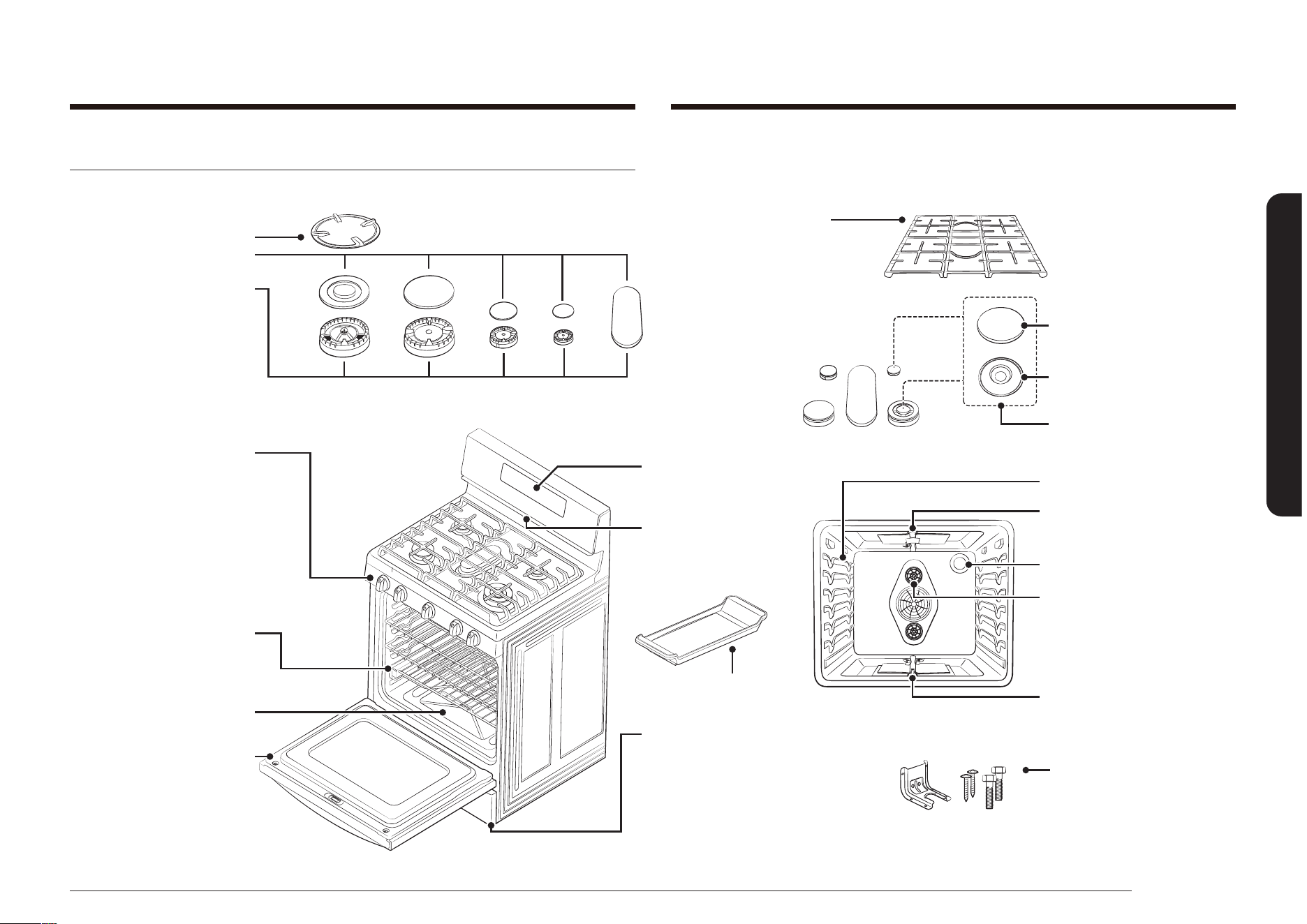
Français 23
Présentation de votre nouvelle cuisinière
Présentation de votre nouvelle cuisinière
Présentation
MODÈLE NX58*565***
* Grille de wok
* Chapeaux des brûleurs de la table
de cuisson
Brûleurs de la table de cuisson
Têtes des brûleurs de la table de
cuisson (5)
Chapeaux des brûleurs de la table de
cuisson (5)
(non représentés sous les brûleurs)
Électrodes (5)
(non représentées sous les brûleurs)
COMPOSANTS DE LA TABLE DE
CUISSON
Grilles en fonte épaisses et continues
- * Grille du brûleur gauche
- * Grille du brûleur central
- * Grille du brûleur droit
Remarque : les grilles de gauche et de
droite sont interchangeables.
* Boutons de commande des brûleurs
de la table de cuisson (5)
- Commande du brûleur avant gauche
- Commande du brûleur arrière gauche
- Commande du brûleur central
- Commande du brûleur arrière droit
- Commande du brûleur avant droit
COMPOSANTS DU FOUR
* Grilles du four (2)
Glisse en rack(1)
(si fournie)
Plancher du four amovible
AFFICHAGE DU GAZ
Surface plate
Ligne concave
l’usage commun
COMPOSANTS DU FOUR
Guide de position des grilles du four
Brûleur de four pour gril
* Eclairage du four (1)
Brûleur de four pour cuisson
PIEDS DE MISE À NIVEAU
RÉGLABLES (4) (non illustrés)
KIT DE SUPPORT
ANTI-BASCULEMENT (1)
Ventilateur de convection (1)
Résistance de convection (non illustré)
Gril (1)
VENTILATION DU FOUR
(centrée sous le tableau de
commande du four)
COMPOSANTS DU TIROIR CHAUFFE-PLAT
Tiroir chauffe-plat amovible (1)
Rails du plateau tournant à extension
complète (2)
Élément de chauffage électrique
(non représentés sous le tiroir)
Porte du four amovible

24 Français
Présentation de votre nouvelle cuisinière
Présentation de votre nouvelle cuisinière
MODÈLE NX58*560***
* Chapeaux des brûleurs de la table
de cuisson
Brûleurs de la table de cuisson
Têtes des brûleurs de la table de
cuisson (5)
Chapeaux des brûleurs de la table de
cuisson (5)
(non représentés sous les brûleurs)
Électrodes (5)
(non représentées sous les brûleurs)
COMPOSANTS DE LA TABLE DE CUISSON
Grilles en fonte épaisses et continues
- * Grille du brûleur gauche
- * Grille du brûleur central
- * Grille du brûleur droit
* Boutons de commande des brûleurs de
la table de cuisson (5)
- Commande du brûleur avant gauche
- Commande du brûleur arrière gauche
- Commande du brûleur central
- Commande du brûleur arrière droit
- Commande du brûleur avant droit
COMPOSANTS DU FOUR
* Grilles du four (2)
Fond du four amovible
COMMANDE NUMÉRIQUE
DU FOUR
COMPOSANTS DU FOUR
Guide de position des grilles du four
Brûleur de four pour gril
* Eclairage du four (1)
Brûleur de four pour cuisson
PIEDS DE MISE À NIVEAU RÉGLABLES (4)
(non illustrés)
KIT DE SUPPORT ANTI-BASCULEMENT (1)
Ventilateur de convection (1)
Gril (1)
VENTILATION DU FOUR
(centrée sous le tableau de
commande du four)
COMPOSANTS DU TIROIR DE RANGEMENT
Tiroir de rangement amovible (1)
Porte du four amovible
Si vous souhaitez acheter un accessoire repéré par un astérisque (*), veuillez contacter le centre d’appels Samsung en appelant au numéro de téléphone indiqué en
dernière page du présent manuel. Vous pouvez également consulter notre site Web de pièces en ligne à l’adresse www.samsungparts.com.
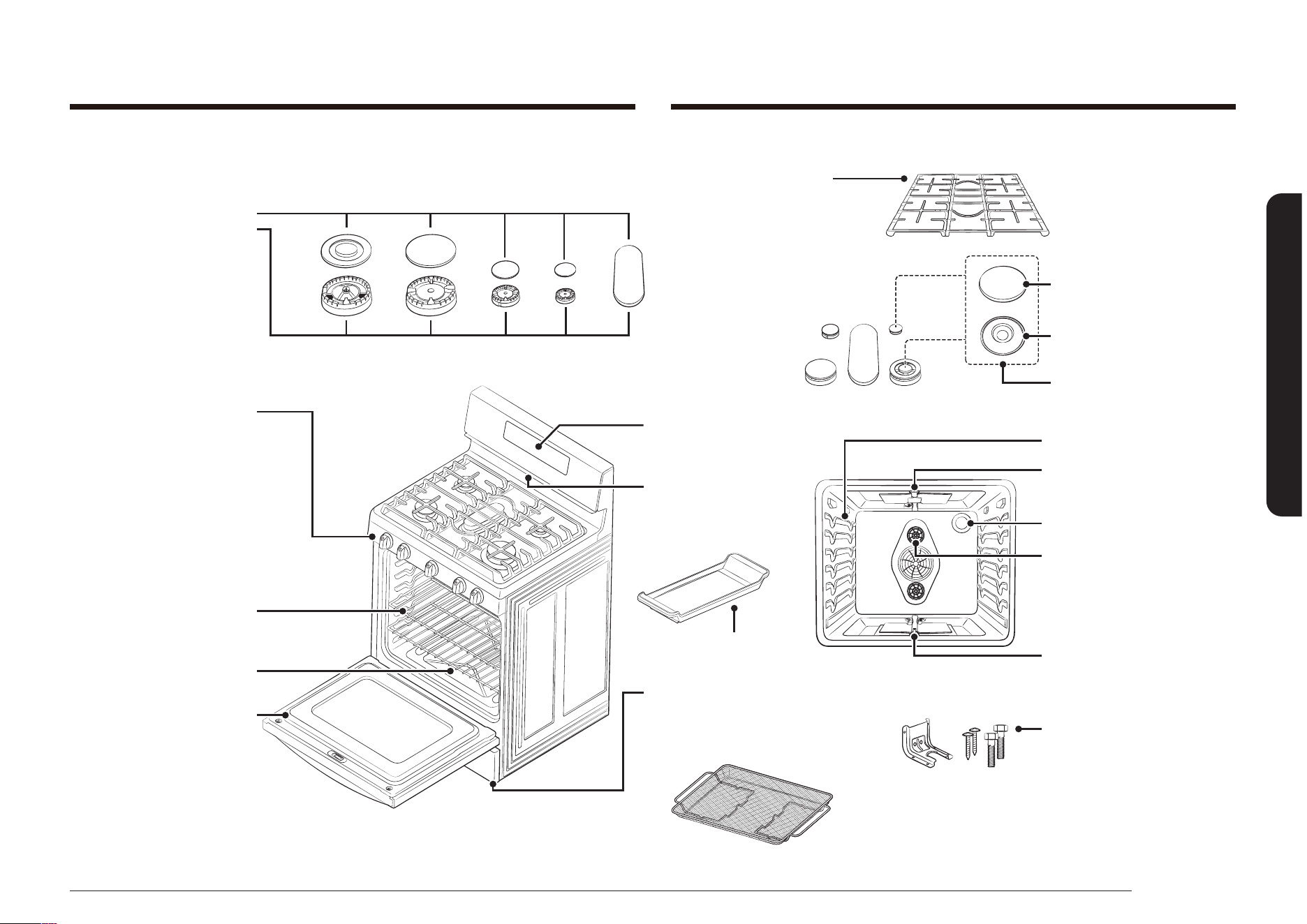
Français 25
Présentation de votre nouvelle cuisinière
MODÈLE NX58*751***
* Chapeaux des brûleurs de la table
de cuisson
Brûleurs de la table de cuisson
Têtes des brûleurs de la table de
cuisson (5)
Chapeaux des brûleurs de la table de
cuisson (5)
(non représentés sous les brûleurs)
Électrodes (5)
(non représentées sous les brûleurs)
COMPOSANTS DE LA TABLE DE
CUISSON
Grilles en fonte épaisses et continues
- * Grille du brûleur gauche
- * Grille du brûleur central
- * Grille du brûleur droit
Remarque : les grilles de gauche et de
droite sont interchangeables.
* Boutons de commande des brûleurs de
la table de cuisson (5)
- Commande du brûleur avant gauche
- Commande du brûleur arrière gauche
- Commande du brûleur central
- Commande du brûleur arrière droit
- Commande du brûleur avant droit
COMPOSANTS DU FOUR
* Grilles du four (2)
Fond du four amovible
COMMANDE NUMÉRIQUE
DU FOUR
COMPOSANTS DU FOUR
Guide de position des grilles du four
Brûleur de four pour gril
* Eclairage du four (1)
Brûleur de four pour cuisson
PIEDS DE MISE À NIVEAU RÉGLABLES (4)
(non illustrés)
KIT DE SUPPORT ANTI-BASCULEMENT (1)
Ventilateur de convection (1)
Gril (1)
VENTILATION DU FOUR
(centrée sous le tableau de
commande du four)
COMPOSANTS DU TIROIR DE RANGEMENT
Tiroir de rangement amovible (1)
Porte du four amovible
Surface plate
Ligne concave
l’usage commun
Plaque de friture par application d'air (1)
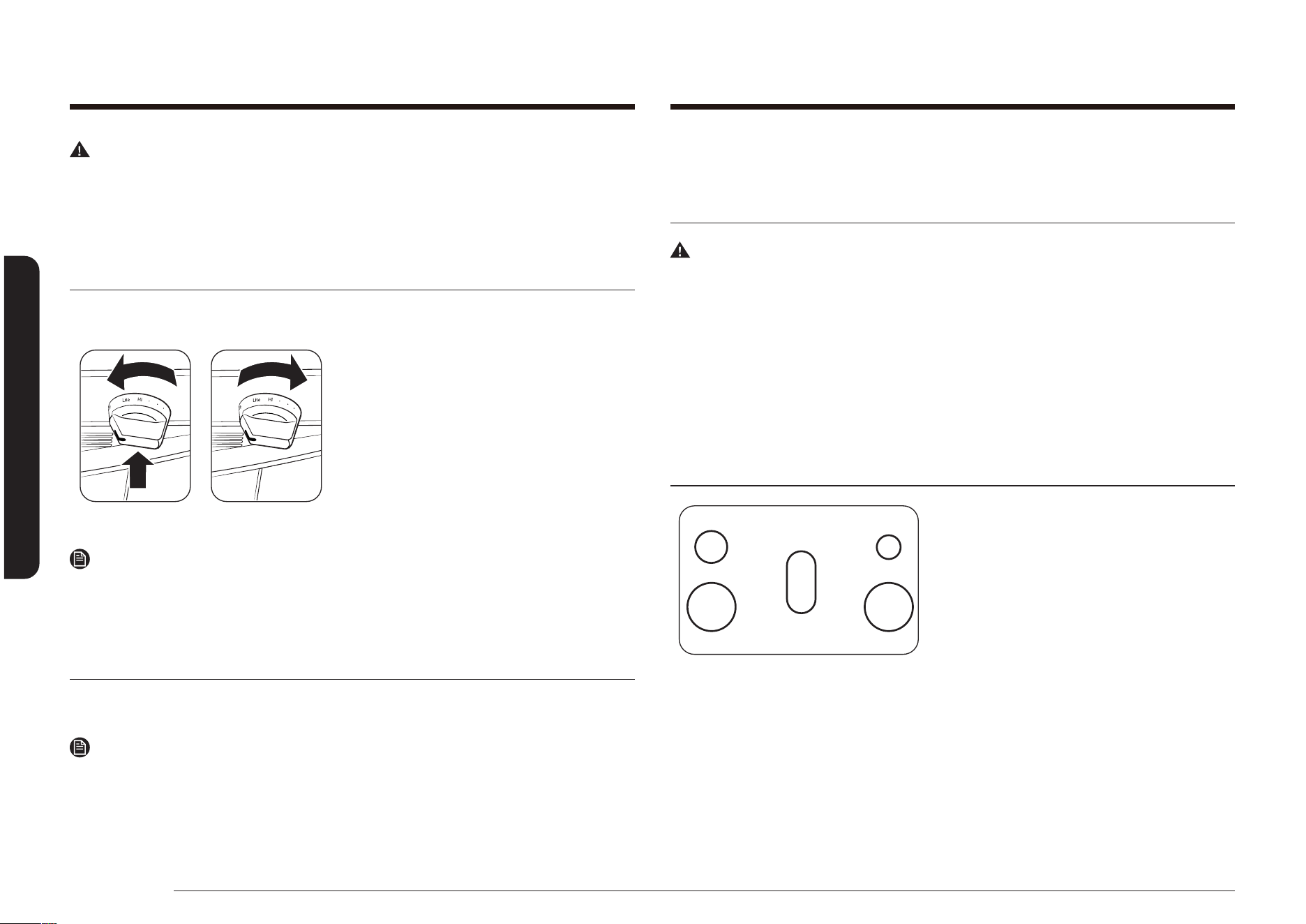
26 Français
Table de cuisson
Table de cuissonTable de cuisson
AVERTISSEMENT
AVANT D'UTILISER LES BRÛLEURS DE SURFACE, assurez-vous de respecter tous
les avertissements de sécurité et précautions listées sur la page 6. Le non-respect
de ces consignes peut entraîner des dégâts matériels, des blessures et/ou des
accidents mortels.
Allumer un brûleur
Assurez-vous que les brûleurs de surface sont correctement positionnés et
assemblés.
1. Réglez le bouton sur la position LITE
(ALLUMAGE) en poussant dessus et en le
faisant tourner. Le système d'allumage
électronique a fonctionné si vous
entendez un « clic ».
2. Une fois le brûleur allumé, réglez
la puissance à l'aide du bouton (ce
qui coupera le système d'allumage
électronique).
Remarque
Nous vous conseillons fortement d'utiliser le brûleur situé sur le côté arrière
gauche pour faire mijoter de la sauce tomate et le brûleur situé sur le côté arrière
droit pour faire fondre du chocolat.
Allumer manuellement un brûleur de surface à gaz
En cas de coupure d'électricité, les brûleurs de surface peuvent toujours être
allumés manuellement.
Remarque
Soyez extrêmement prudents lorsque vous allumez un brûleur de surface
manuellement.
1. Approchez un allume-gaz du brûleur de surface que vous souhaitez allumer.
2. Réglez le bouton de ce brûleur sur la position LITE (ALLUMAGE) en poussant
dessus et en le faisant tourner.
3. Une fois le brûleur allumé, mettez le bouton de commande et le brûleur sur le
réglage souhaité.
Sélection de la taille de la amme
AVERTISSEMENT
Si les ammes dépassent la taille des ustensiles, la cuisson ne sera pas plus rapide,
mais il existe un risque d'incendie et/ou de blessures.
Les ammes du brûleur doivent toujours rester en-dessous des ustensiles. Les
ammes ne doivent jamais dépasser le fond de la surface et/ou les côtés des
ustensiles.
Observez toujours les ammes lorsque vous réglez la chaleur avec le(s) bouton(s)
de commandes. Les ammes doivent toujours correspondre à la taille des
ustensiles utilisés.
Brûleurs de surface à gaz et boutons de commandes
ArG ArD
AvG AvD
CENTRE
La table de cuisson de votre cuisinière à
gaz est équipée de cinq brûleurs à gaz. Tous
les brûleurs scellés de la table de cuisson
sont conçus à orices ouverts an de vous
offrir un assemblage facile et une utilisation
précise et sûre. Grâce aux différentes tailles
de brûleurs vous bénéciez d’une source
de chaleur appropriée pour la cuisson
souhaitée.
Le brûleur situé sur le côté arrière droit vous offre une performance de cuisson
précise pour des aliments délicats qui nécessitent une cuisson lente à basse
température. Sur le brûleur situé sur le côté arrière droit vous pouvez utiliser le
réglage LO (FAIBLE) pour mijoter à une très basse température.
Les brûleurs situés sur le côté arrière gauche et au centre sont des brûleurs à
usage général qui peuvent être utilisés pour la plupart des cuissons. Les réglages
HI (ÉLEVÉ) à LO (FAIBLE) vous offrent une large gamme de températures de
cuisson pour satisfaire vos besoins de cuisson.
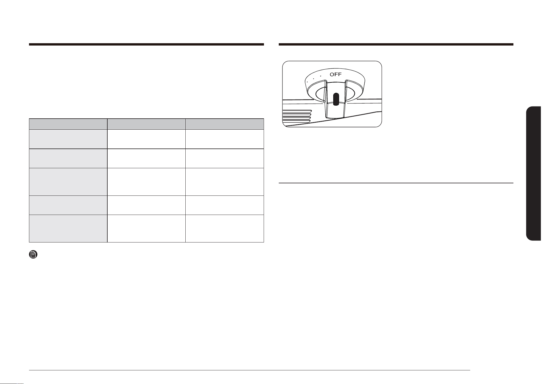
Français 27
Table de cuisson
Chaque brûleur de surface possède un
bouton de commande avec des réglages
de LO (BAS) à HI (FORT). Le réglage
LITE (ALLUMER) de chaque brûleur est
uniquement utilisé pour allumer la amme.
Le système d'allumage électronique
produit des étincelles lorsque le bouton
de commande est sur la position LITE
(ALLUMER).
L'indicateur du brûleur de surface à côté du
bouton de commande afche quel brûleur
est réglé par le bouton.
Utilisation des récipients
L'utilisation de l'ustensile de cuisine approprié permet d'éviter de nombreux
problèmes tels qu'une cuisson inégale ou un temps de cuisson trop long. Utiliser
une casserole adaptée permet de réduire les temps de cuisson et de cuire
uniformément les aliments. Vériez que les récipients ont les caractéristiques
suivantes :
• Fond plat et bords droits.
• Couvercle hermétique.
• Le poids du manche ne fait pas incliner la casserole.
• Casserole bien équilibrée.
• La taille de la casserole est adaptée à la quantité d'aliments à préparer et à la
taille du brûleur de surface.
• Matériau permettant une bonne conduction de la chaleur.
• Le diamètre du récipient doit toujours correspondre à celui de la amme du
brûleur de surface.
Le matériau de l'ustensile de cuisine assure que la chaleur émise par le brûleur de
surface se propage uniformément et rapidement au fond de la casserole.
ALUMINIUM : Excellent conducteur thermique. Certains types d'aliments font
noircir l'aluminium (Les ustensiles en aluminium anodisé résistent aux taches et
aux piqûres).
CUIVRE : Excellent conducteur thermique mais se décolore facilement.
Les brûleurs situés sur le côté avant droit et gauche ont une puissance maximale.
Ces brûleurs peuvent également être utilisés pour une cuisson générale, mais
ils ont été conçus pour chauffer rapidement des récipients de grande taille. Les
brûleurs situés sur le côté avant droit et gauche diffusent la chaleur grâce à un
cercle de ammes plus grand. Cela permet une meilleure répartition de la chaleur
pour des récipients de grande taille (12”/30,5 cm) ou des casseroles et poêles plus
grandes.
POSITION DU BRÛLEUR FONCTION TYPE D'ALIMENTS
AVANT DROIT (AvD) Cuisson rapide
Faire bouillir des
aliments
ARRIÈRE DROIT (ArD)
Mijotage à basse
température
Chocolat, plats mijotés,
sauces
CENTRE Cuisson au gril
Crêpes, hamburgers,
œufs sur le plat,
sandwichs chauds
AVANT GAUCHE (AvG) Cuisson rapide
Faire bouillir des
aliments
ARRIÈRE GAUCHE (ArG)
Cuisson
Mijotage à basse
température
Aliments divers
Sauce tomate*, Plats
mijotés
Remarque
* La sauce tomate doit etre remuee a feu doux.
Le brûleur ovale central peut également être utilisé pour des casseroles et poêles
plus grandes, mais il a été conçu pour une utilisation avec la grille centrale et/
ou la grille de brûleur centrale comme accessoire (si fournie). Sur le brûleur ovale
la chaleur est répartie de façon plus homogène sur la grande zone de cuisson
centrale.
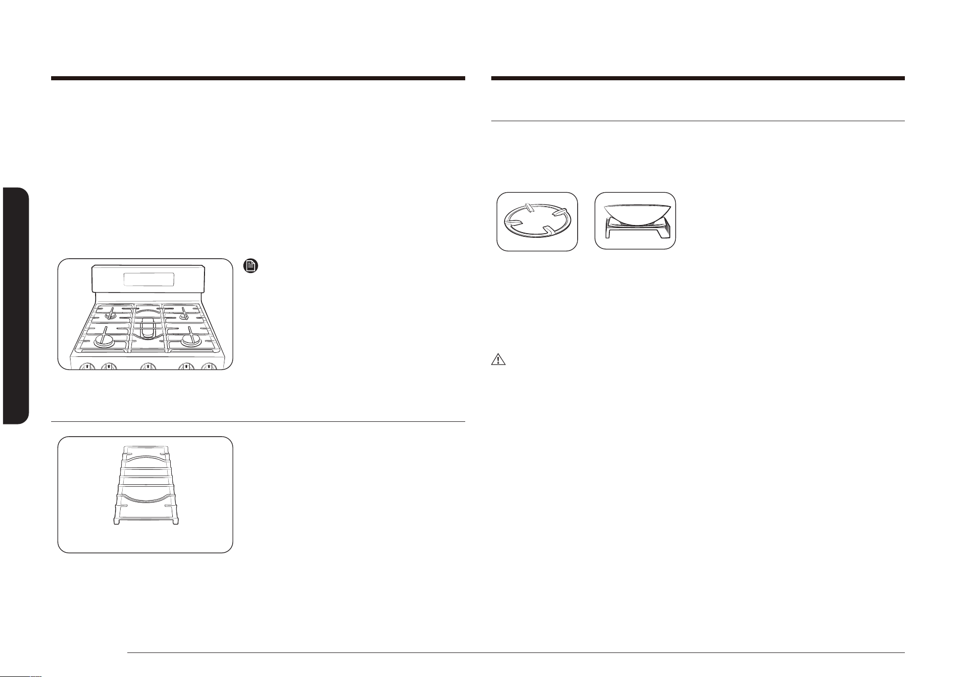
28 Français
Table de cuisson
Table de cuisson
Wok grate (wok grille) (NX58*565*** uniquement)
Les woks permettent de faire sauter, mijoter, frire et pocher les aliments.
La grille fournie avec le wok peut soutenir une casserole ou un wok de 12 à 14”.
Comment utiliser la grille du wok
1. Avant de mettre en place la grille,
vériez que le brûleur est coupé et que
la grille est froide.
2. Positionnez la grille du wok sur l’une de
deux grilles latérales.
3. Placez un wok sur la grille du wok.
(Veillez à ce que le wok soit bien stable
sur la grille du wok.)
4. Allumez le brûleur et réglez la taille de
la amme.
ATTENTION
• NE retirez PAS la grille avant qu’elle-même, les autres grilles et la surface de
cuisson n’aient totalement refroidies.
• la grille du wok peut devenir très chaude lorsque vous utilisez la table de
cuisson, le four ou les systèmes de gril. Portez toujours de maniques lorsque
vous devez la manipuler.
• N’utilisez jamais de fait-tout ou de casserole à fond plat sur la grille du wok
ou un wok de diamètre inférieur à celui de l’anneau du wok. Sinon, il y a des
chances que la casserole, le fait-tout ou le wok bascule.
• Si vous utilisez un wok surdimensionné, les ammes risquent de s’étendre sur
les côtés et d’endommager la table de cuisson.
• Veillez à ce que le wok soit bien stable sur la grille du wok.
ACIER INOXYDABLE : Conducteur thermique lent entraînant une cuisson inégale.
Durable, facile à nettoyer et résistant aux taches.
FONTE : Mauvais conducteur, mais conserve bien la chaleur. La cuisson n'est
uniforme qu'une fois la température de cuisson atteinte.
CASSEROLE ÉMAILLÉE : Les caractéristiques de chauffage varient en fonction du
matériau de base.
VERRE : Conducteur thermique lent. Des ustensiles en verre sont conçus pour
deux utilisations - sur la table de cuisson et dans le four. Utilisez les ustensiles
uniquement si leur utilisation est désignée.
Remarque
Ne placez pas de petite casserole ou plat
avec un fond d’un diamètre d’environ 6” ou
moins sur la grille centrale. Sinon, il y a des
chances que la casserole ou le plat bascule.
Nous vous recommandons fortement de
placer les petits plat ou casseroles à l’arrière
de l’une des deux grilles latérales.
Grille du brûleur central
Grille du brûleur central
Les cuisinières à gaz Samsung sont livrées
avec une grille pour le brûleur central.
Cette grille se place au-dessus du brûleur
ovale central. La grille du brûleur central
ne doit être placée sur aucun autre brûleur.
N’utilisez pas d’autres grilles centrales avec
cette cuisinière.
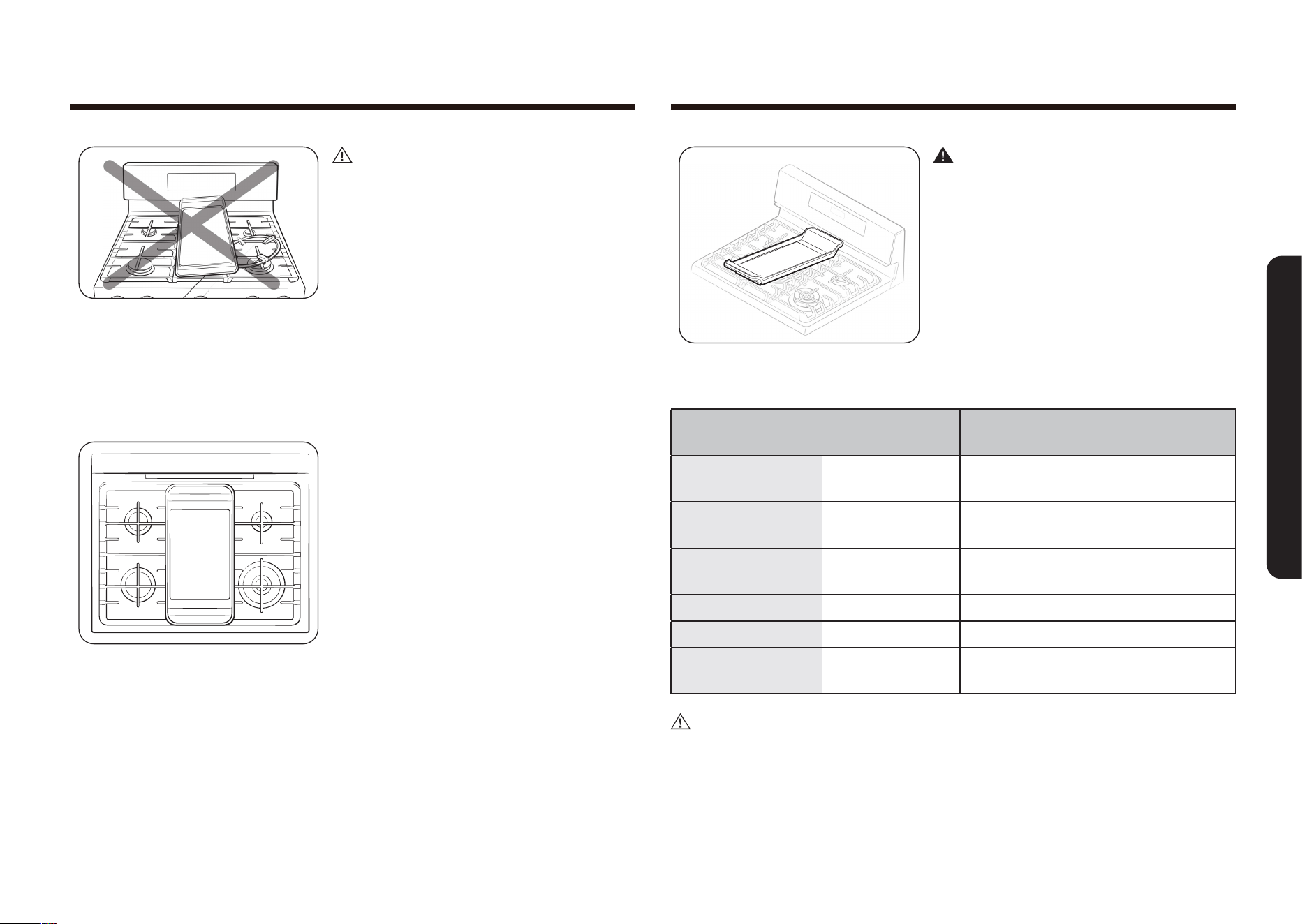
Français 29
Table de cuisson
Avertissement
Ne retirez PAS la grille centrale lors de
l’utilisation du gril.
Comment cuisiner : Préchauffez le gril conformément au guide ci-dessous puis
ajustez en fonction des conditions de cuisson.
Type d'aliment
Temps de
préchauffage
Condition de
préchauffage
Condition de
cuisson
Crêpes 5 min
5 (MED-HI)
(MOYEN-ÉLEVÉ)
4 (MED) (MOYEN)
Hamburgers 5 min 7 (HI) (ÉLEVÉ)
5 (MED-HI)
(MOYEN-ÉLEVÉ)
Œufs au plat 5 min 7 (HI) (ÉLEVÉ)
5 (MED-LO)
(MOYEN-FAIBLE)
Bacon - Aucune 4 (MED) (MOYEN)
Saucisses 5 min 7 (HI) (ÉLEVÉ) 5 (MED) (MOYEN)
Sandwich au
fromage fondu
4 min 7 (HI) (ÉLEVÉ)
6 (MED-HI)
(MOYEN-ÉLEVÉ)
ATTENTION
• Ne retirez PAS le gril avant que les grilles, la surface de cuisson et le gril soient
totalement refroidis.
• Le gril sur la table de cuisson peut devenir très chaud lors de l’utilisation de
la table de cuisson, du four ou des systèmes de gril. Servez-vous toujours de
maniques lorsque vous placez ou retirez le gril.
ATTENTION
N’utilisez pas la grille du wok et le gril
simultanément.
Utilisation du gril
Le gril à revêtement non xé offre une très grande surface de cuisson pour la
viande, les crêpes ou tout autre aliment généralement cuisiné dans une poêle à
frire.
Comment positionner le gril : Le gril ne peut
être utilisé qu’avec le brûleur central. Il doit
être correctement positionné au centre de la
grille, comme indiqué ci-dessous.

30 Français
Utilisation du four
Utilisation du four Utilisation du four
Tableaux de commande et afchages du four
MODÈLE NX58*565***
03 04 05 09 07
15 14 16 17 18 06
08
12
11
13
01 02
10
MODÈLE NX58*560***
03 04 05 09 07
15 14 16 17 18 06
0802
12 10
01 11
Remarque
• Déposez délicatement le gril sur la grille centrale.
• Il peut être nécessaire de régler les paramètres du gril si celui-ci est utilisé
pendant une période prolongée.
• Du fait qu’il va sécher avec l’usage, votre gril se décolorera avec le temps.
• Après utilisation, rangez le gril uniquement après qu’il ait refroidi.
Remarque importante :
• NE FAITES PAS surchauffer le gril. Ceci pourrait endommager le revêtement
non xé.
• N’utilisez PAS d’ustensiles en métal pouvant endommager la surface du gril. Ne
vous servez PAS du gril comme d’une planche à découper.
• Ne placez et ne rangez PAS d’éléments sur le gril.
• Ne retournez PAS le gril et n’utilisez pas sa face inférieure pour la cuisson.
Utilisez uniquement la face supérieure du gril.
• N’utilisez PAS le gril pour toute autre fonction que la cuisson.
• Évitez de cuisiner des aliments très gras. Il pourrait y avoir des éclaboussures
de graisse.
• Le gril peut devenir chaud lorsque les brûleurs autour sont en marche.
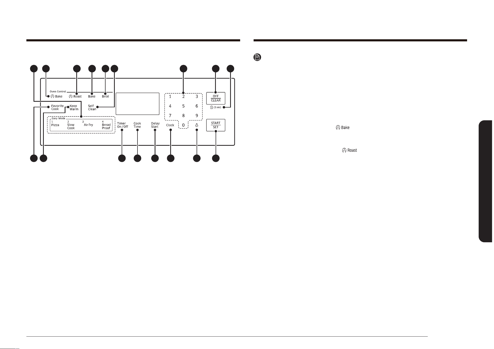
Français 31
Utilisation du four
Remarque
Le four est contrôlé au moyen de touches tactiles. Utilisez les touches suivantes
pour programmer et utiliser les fonctions de cuisson, de nettoyage et de minuterie.
Les réglages programmés et l'état des modes de cuisson s'afchent sur l'écran
numérique.
Commandes des fonctions spéciales, du four et de la durée
01 CUISSON FACILE : Permet d'activer automatiquement la fonction de cuisson
facile dans le compartiment du four.
02 CUISSON PAR CONVECTION( ) : Permet d'activer la fonction de cuisson par
convection Utilisez cette fonction pour cuire de grandes quantités d'aliments
sur plusieurs niveaux en même temps.
03 RÔTISSAGE PAR CONVECTION( ) : Permet d'activer la fonction de
rôtissage par convection pour faire cuire de gros morceaux de viande.
04 CUISSON TRADITIONNELLE : Permet d'activer la fonction de cuisson
traditionnelle pour faire cuire uniformément les aliments à l'aide du brûleur
situé dans la sole du four.
05 GRIL : Permet d'activer la fonction de gril pour faire cuire des aliments à l'aide
du brûleur situé dans le haut du four.
06 DÉPART/RÉGLAGE : Permet de démarrer les fonctions de cuisson, de nettoyage
et/ou de minuterie du four.
07 ARRÊT/EFFACER : Permet d'annuler tous les programmes en cours, à
l'exception de l'horloge et de la minuterie.
08 VERROUILLAGE 3 S : Permet de désactiver les touches du tableau de
commande pour éviter la mise en marche accidentelle du four et de verrouiller
la porte pour éviter de faire basculer la cuisinière. Les touches ne fonctionnent
pas et la porte du four est verrouillée tant que cette fonction reste activée.
09 TOUCHES NUMÉRIQUES : Permettent de régler les durées, les températures et
les programmes de cuisson automatique du four.
10 MAINTIEN AU CHAUD : Permet de conserver au chaud les aliments une fois la
cuisson terminée. Ceci abaisse et maintient la température du four de
150 °F à 200 °F (66 °C à 93 °C).
11 AUTO-NETTOYAGE : Permet d'activer la fonction d'auto-nettoyage du four. Elle
consiste à faire chauffer l'appareil à très haute température an de brûler les
résidus alimentaires.
MODÈLE NX58*751***
03 04 05 09 07
15 14 16 17 18 06
0802
12 10
01 11
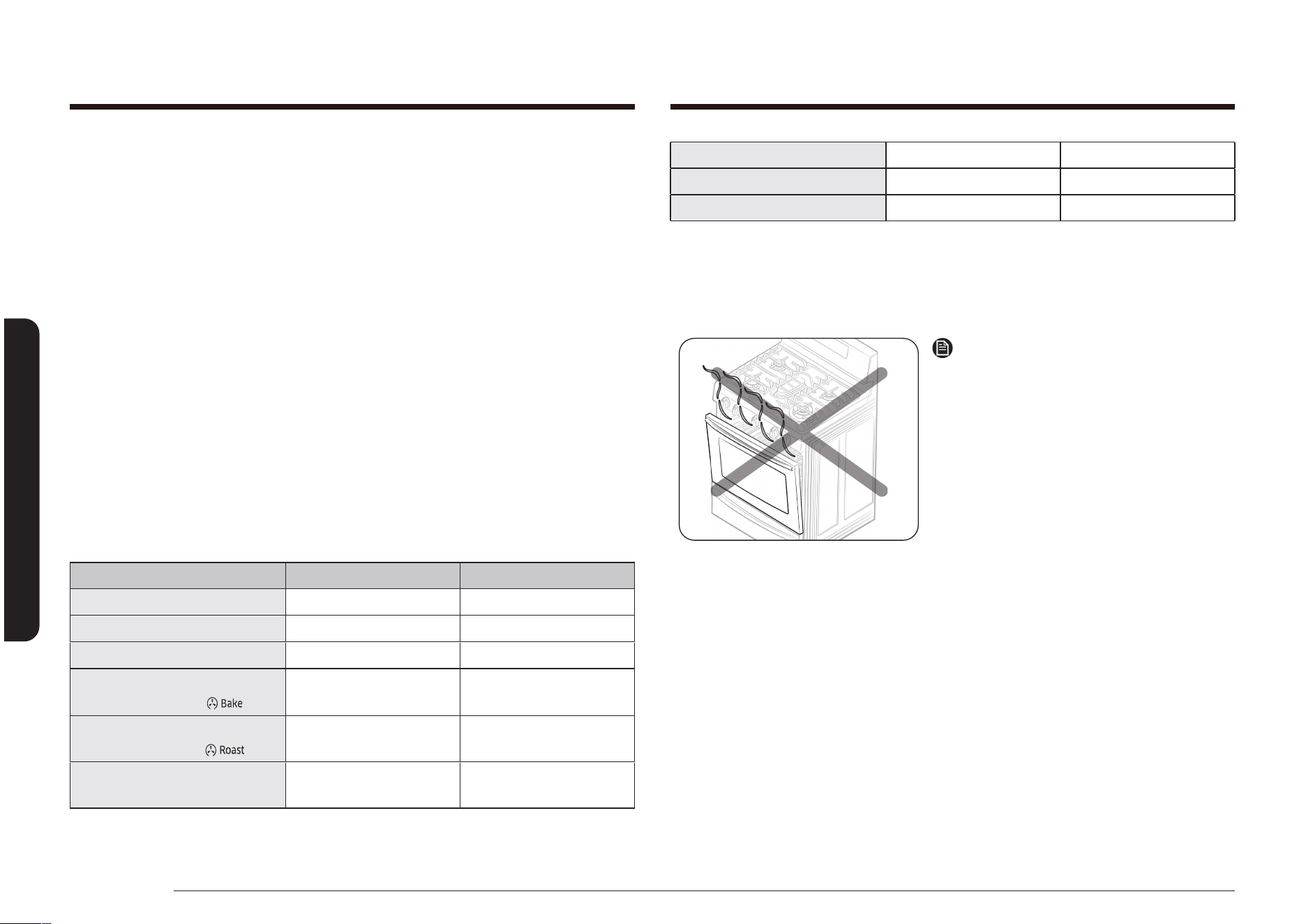
32 Français
Utilisation du four
Utilisation du four
MAINTIEN AU CHAUD - 3 heures
TIROIR CHAUFFE-PLAT * - 3 heures
BREAD PROOF (LEVÉE) - 12 heures
* Model NX58*565*** uniquement
Si vous choisissez Conversion On at Convection Bake and/or Convection Roast
(Conversion activée pour la cuisson par convection et/ou le rôtissage par
convection), vous pouvez régler la température minimale sur 175 °F (79 °C).
Remarque
Cuisinez et/ou grillez les aliments
toujours avec la porte du four fermée.
Si la porte du four reste ouverte lors de
son fonctionnement, il s’arrêtera dans 1
minute. Ce n’est pas un dysfonctionnement
du produit. Le four se relancera
automatiquement dès que vous fermerez la
porte.
Mode d’application : Conv. Bake (Cuisson
par conv.), Conv. Roast (Rôtissage
par convection), Bake (Cuisson), Broil
(Gril), Pizza (Pizza), Slow Cook (Cuisson
lente), Dehydrate (déshydrater), Bread
Proof (levée), Favorite Cook (Cuisson
Personnalisée), Air Fry (Friture par
application d'air).
12 CUISSON PERSONNALISÉE : Permet d'activer la fonction de cuisson
personnalisée. Vous pouvez ainsi préprogrammer trois modes de cuisson et les
lancer à l'aide d'une seule touche.
13 TIROIR CHAUFFE-PLAT(MODÈLE NX58*565***) : Permet d'activer le tiroir
chauffe-plat. La résistance électrique située sous le tiroir offre trois réglages
pour conserver les aliments cuits au chaud.
14 TEMPS DE CUISSON : Appuyez d'abord sur ce bouton, puis utilisez le pavé
numérique pour dénir le temps de cuisson des aliments. Le four s'arrêtera
automatiquement une fois la durée écoulée.
15 ACTIVATION/DÉSACTIVATION DE LA MINUTERIE : Permet de sélectionner la
fonction de minuterie pour dénir le temps de cuisson souhaitée.
16 DÉPART DIFFÉRÉ : Permet de régler le départ et l'arrêt automatique du four.
Utilisable avec les fonctions Bake, Convection Bake, Convection Roast, Cook
Time et Self Clean (Cuisson traditionelle, Cuisson traditionelle par convection,
Rôtissage par convection, Temps de cuisson et Auto-nettoyage).
17 HORLOGE : Permet de régler l'heure.
18 ÉCLAIRAGE DU FOUR : Permet d'activer ou de désactiver l'éclairage du four.
RÉGLAGES MINIMUM ET MAXIMUM
Toutes les fonctions répertoriées dans le tableau suivant sont associées à des
réglages de température et de durée mini et maxi.
FONCTION RÉGLAGE MINIMUM RÉGLAGE MAXIMUM
CUISSON TRADITIONNELLE 150 °F (66 °C) 550 °F (288 °C)
GRIL Lo (Faible) Hi (Élevé)
AUTO-NETTOYAGE 2 heures 4 heures
CUISSON PAR
CONVECTION ( )
150 °F (66 °C) 550 °F (288 °C)
RÔTISSAGE PAR
CONVECTION ( )
150 °F (66 °C) 550 °F (288 °C)
AIR FRY (FRITURE PAR
APPLICATION D'AIR)
350 °F (177 °C) 500 °F (260 °C)
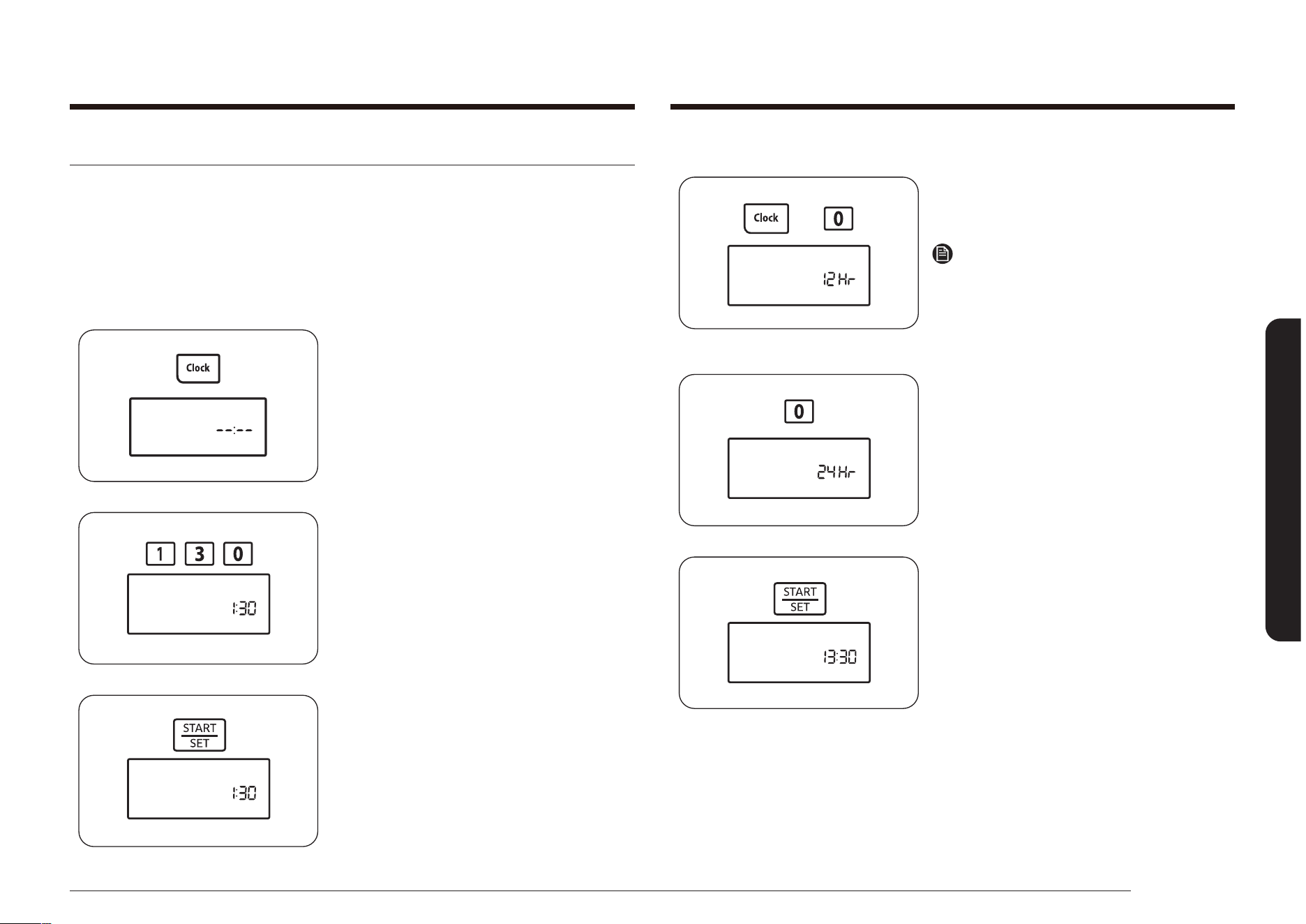
Français 33
Utilisation du four
Comment passer du format 12 heures au format 24 heures ?
1. Appuyez sur les touches Clock (Horloge)
et 0 pendant 3 secondes.
Le format actuel s'afche (ex : 12Hr).
Remarque
Si vous appuyez d'abord sur une touche
puis sur l'autre, -- -- s'afche.
Appuyez sur la touche OFF/CLEAR (ARRÊT/
EFFACER) et recommencez.
2. Appuyez sur la touche 0 pour alterner
entre les formats 12 heures et
24 heures.
24Hr apparaît à l'écran.
3. Appuyez sur la touche START/SET
(DÉPART/RÉGLAGE) pour changer le
mode d'afchage de l'horloge.
L'heure est afchée au format
24 heures.
Réglage de l'horloge
L'horloge doit être réglée sur l'heure correcte an que la minuterie automatique
du four fonctionne correctement. Vous pouvez afcher l'heure au format 12 ou
24 heures. Par défaut, l'heure s'afche au format 12 heures.
L'heure ne peut pas être modiée durant la cuisson minutée, le départ différé,
l'auto-nettoyage ou la fonction Sabbath (Shabbat).
Comment régler l'horloge ?
1. Appuyez sur la touche Clock (Horloge).
2. Saisissez l'heure actuelle en heures et
minutes à l'aide du pavé numérique
(ex. : 1, 3, 0).
L'écran afche l'heure, et le symbole
Start (Démarrage) clignote.
3. Appuyez sur le bouton START/SET
(DÉPART/RÉGLAGE) pour régler et
démarrer l'horloge.
L'écran afche l'heure, et le symbole
Start (Démarrage) s’éteint.
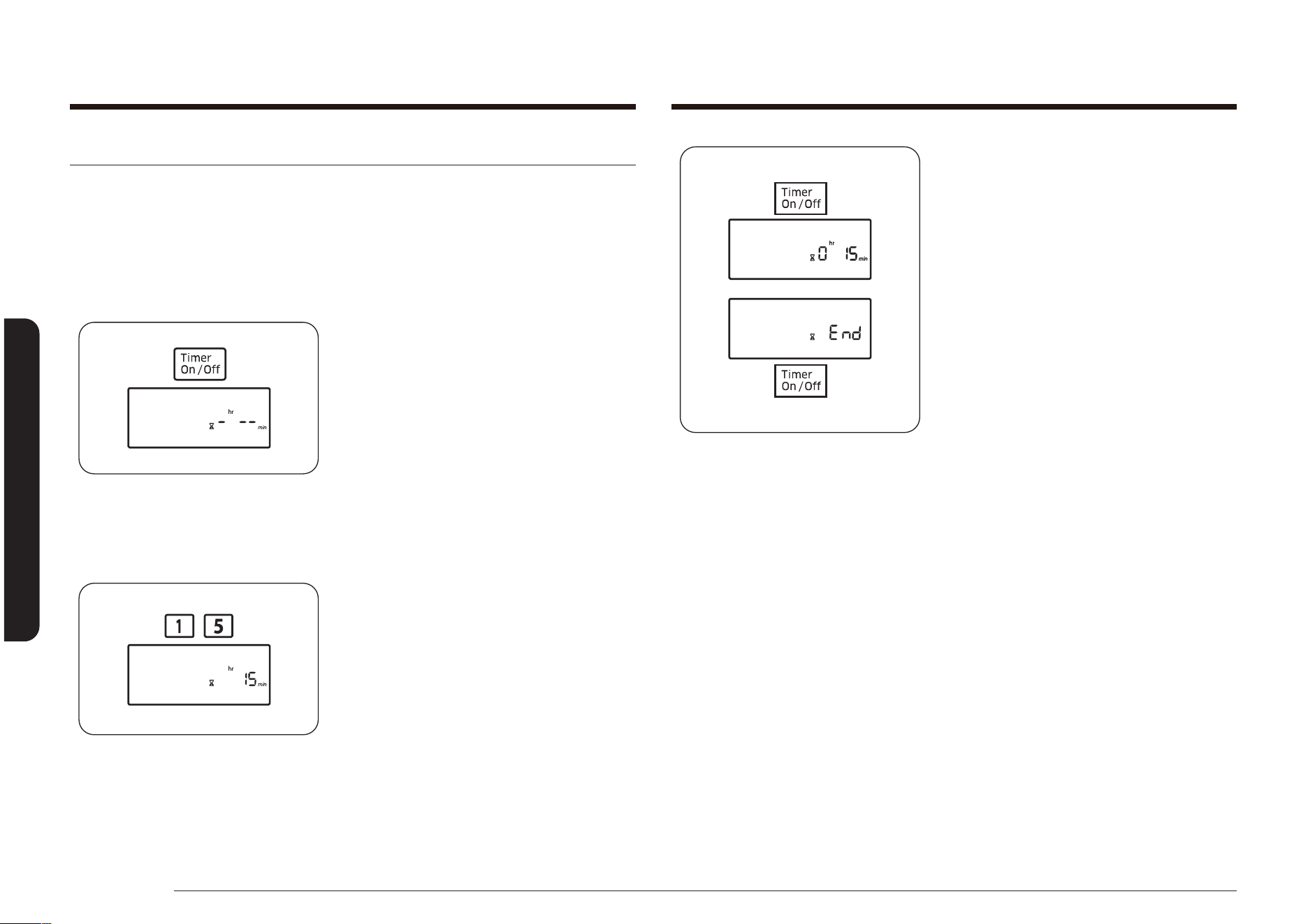
34 Français
Utilisation du four
Utilisation du four
3. Appuyez sur le bouton Timer On/
Off (Activation/Désactivation de la
minuterie) pour démarrer la minuterie.
Le temps restant s'afche. Une fois le
temps réglé écoulé, le four émet un
signal sonore et l'indication End (Fin)
s'afche jusqu'à ce que vous appuyiez
sur la touche Timer On/Off (Activation/
Désactivation de la minuterie). Après
avoir appuyé sur la touche, l'écran
afche l'heure actuelle à nouveau.
Vous pouvez annuler la minuterie à
tout moment en appuyant sur la touche
Timer On/Off (Activation/Désactivation
de la minuterie).
Activation/désactivation de la minuterie
La minuterie décompte le temps restant et un signal sonore retentit une fois le
temps réglé écoulé. Elle ne permet pas de démarrer ou d’arrêter les fonctions de
cuisson. Vous pouvez utiliser la minuterie de cuisine en même temps que toute
autre fonction de la cuisinière et la régler sur n’importe quelle durée comprise
entre 1 minute et 9 heures et 99 minutes.
Comment régler la minuterie ?
1. Appuyez sur la touche Timer On/
Off (Activation/Désactivation de la
minuterie) une seule fois pour les
heures/minutes et deux fois pour les
secondes. Appuyez trois fois sur le pavé
pour désactiver la minuterie de cuisine
ou l’annuler avant qu’elle ne se mette en
marche.
L'écran afche Timer (Minuterie), et
-
hr
--
min
clignote à l'écran. (Les caractères
hr et min ne s’afchent pas sur le
modèle NX58*560***, NX58*751***.)
2. Appuyez sur les touches du pavé
numérique pour saisir la durée que
vous souhaitez en minutes, en heures et
minutes ou en secondes (p. ex. 1, 5).
Le temps réglé s'afche.
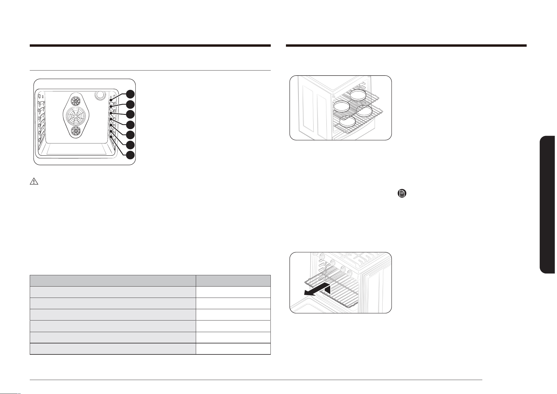
Français 35
Utilisation du four
Positionnement des grilles du four
5
6
7
4
3
2
1
Les grilles du four sont amovibles et
peuvent être positionnées de sept façons
différentes. Chaque grille dispose d'une
butée d'arrêt pour éviter de les retirer
accidentellement complètement. Un
positionnement approprié des grilles du
four apportera de meilleurs résultats de
cuisson. Le schéma à droite
ATTENTION
• Ne couvrez pas une grille du four avec du papier aluminium. Cela peut gêner la
circulation de la chaleur, entraînant une cuisson faible.
• Ne placez pas de feuille d’aluminium au fond du four. Vous risquez
d’endommager la surface du fond du four.
• Disposez les grilles du four uniquement pendant que le four est froid.
• Lorsque vous posez la grille sur la position la plus haute (position 7), veillez à
ce qu'elle soit placée de façon stable sur le stoppeur brocardé an de ne pas
tomber.
Hauteurs de grille
TYPE D'ALIMENTS HAUTEUR DE GRILLE
Hamburgers et steaks 6 ou 7
Toasts 5 ou 6
Biscuits, mufns, brownies, cookies ou tartes 4
Couronne ou quatre-quarts 3
Gâteau des anges, tartes 2
Rôtis (petits ou gros), jambon, dinde 1 ou 2
Cuisson de gâteaux étagés
• Centrer les moules dans le four permet
une meilleure cuisson.
• Si vous faites cuire plusieurs produits en
même temps, veillez à laisser un espace
de 2,5 à 3,8 cm (1 à 1,5”) entre eux.
• Si vous utilisez plusieurs grilles,
positionnez-les aux hauteurs 2 et 5.
• Si vous utilisez plusieurs grilles avec la
cuisson à convection, positionnez-les
aux hauteurs 2 et 5.
• Placez deux moules à l’arrière de la
grille supérieure et les deux autres
moules à l’avant de la grille inférieure.
Remarque
Un positionnement approprié des aliments
dans le four vous aidera à obtenir la
meilleure cuisson possible.
Pour enlever une grille du four :
1. Tirez la grille horizontalement vers
l'extérieur jusqu'à ce qu'elle bute.
2. Soulevez l’avant de la grille du four, puis
tirez pour la retirer du four.
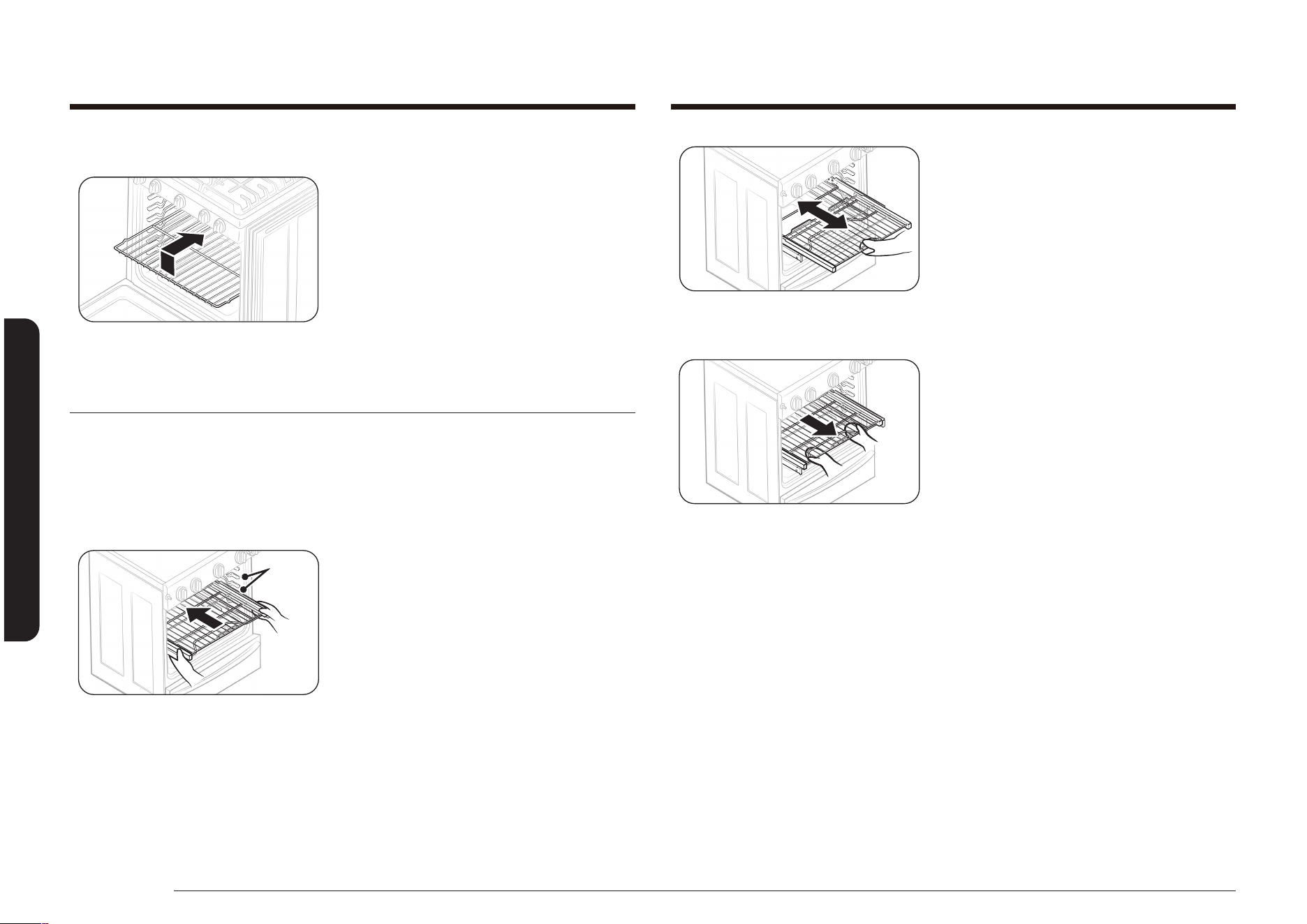
36 Français
Utilisation du four
Utilisation du four
• N’utilisez que la poignée de la grille
coulissante pour la faire sortir du four
ou la faire rentrer. Si vous saisissez le
cadre pendant l’utilisation de la grille,
vous pouvez tirer l’ensemble de la grille
coulissante en dehors du four.
Comment retirer la grille coulissante
• Assurez-vous que la grille coulissante
est en position fermée et que le four est
éteint et a refroidi, puis saisissez et tirez
à la fois sur la grille et le cadre.
Pour remettre une grille dans le four :
1. Placez le bord arrière de la grille sur le
support souhaité.
2. Soulevez l’avant de la grille, puis faites-
la glisser dans le four.
Comment utiliser la grille coulissante
(NX58*565*** uniquement)
La grille entièrement coulissante facilite la préparation des plats, en particulier
lorsqu’ils sont cuisinés dans des récipients lourds. La grille coulissante, dotée de
2 rails coulissants, vous permet d’allonger la grille et d’y disposer des aliments en
dehors du four pour un accès et un retrait plus facile.
Comment installer la grille coulissante
Glissières
de la
grille
• Assurez-vous que la grille coulissante
est en position fermée et insérez-la
entièrement le long des rails de guidage.

Français 37
Utilisation du four
Ventilation du four
Ventilation du four
La ventilation du four se situe sous le four.
Ne bloquez pas ou ne placez pas d’objet en
face de la ventilation du four. Une bonne
circulation de l’air évite les problème de
combustion des brûleurs du four et permet
une meilleure cuisson. La ventilation et
la surface qui l’entoure peuvent chauffer,
faites donc attention en plaçant des
éléments près de la ventilation. La vapeur
chaude pourrait chauffer ou faire fondre
des objets placés devant la ventilation.
Éclairage du four
Éclairage
du four
Le four dispose d’une lumière située sur la
paroi du fond, dans le coin supérieur droit.
La lumière peut être allumée ou éteinte en
appuyant sur la touche Oven Light (Lumière
du four) sur le tableau de commande. La
lumière du four vous permet de vérier
l’évolution de la cuisson sans ouvrir le
four. Utilisez toujours une ampoule pour
électroménager de 40 watts pour remplacer
l’éclairage du four. Voir page 67 pour les
consignes de changement de l’ampoule.
ATTENTION
N'installez pas la grille coulissante juste
au-dessus de la grille plate et la grille
encastrée. Vous ne pourrez pas l'installer
correctement et la grille pourrait tomber.
Remarque
Vous pouvez installer la grille coulissante sur n'importe quel niveau sauf le niveau
le plus haut (niveau 7) et le plus bas (niveau 1) dans le four.

38 Français
Utilisation du four
Utilisation du four
4. Appuyez sur la touche START/SET
(DÉPART/RÉGLAGE).
Le four s'allume automatiquement et le
préchauffage démarre. L'écran afche
un « • » clignotant, ainsi que 150 °,
Bake (Cuisson traditionnelle), et le
symbole du mode de cuisson, jusqu'à ce
que le four atteigne cette température.
Ensuite, l'écran n'afche que la
température actuelle du four.
Lorsque le four atteint la température
de cuisson souhaitée, un signal sonore
retentit 6 fois.
5. Placez les aliments dans le four, puis
fermez la porte. Le préchauffage est
très important pour garantir une bonne
cuisson.
6. Une fois la cuisson terminé, sortez
les aliments du four, fermez la porte,
puis appuyez sur la touche OFF/CLEAR
(ARRÊT/EFFACER).
Le four s'éteint et l'écran afche l'heure
du jour.
Pour changer une température de cuisson programmée, appuyez sur la touche
Bake (Cuisson traditionnelle), entrez la nouvelle température, puis appuyez sur la
touche START/SET (DÉPART/RÉGLAGE). Si la température du four est supérieure au
nouveau réglage, un signal sonore retentit 6 fois, puis afche les données entrées.
Le four termine la cuisson avec la nouvelle température.
Faire cuire de la pâte crue
La fonction Bake (Cuisson traditionnelle), vous permet de programmer la cuisson
du four à une température comprise entre 66°C (150 °F) et 288 °C (550 °F).
Comment régler la température du four ?
1. Positionnez la grille sur l'emplacement
de votre choix.
2. Appuyez sur le bouton Bake (Cuisson
traditionnelle). Un signal sonore retentit
à chaque fois que vous appuyez sur une
touche.
La température par défaut (350°) et
l'indicateur Start (Démarrer) clignotent à
l'écran. Si la température par défaut est
celle que vous désirez, passez à l'étape
4.
3. Appuyez sur les touches du pavé
numérique pour saisir la température de
cuisson souhaitée (par exemple 3, 7, 5).
La température de cuisson et l'indicateur
Start (Démarrer) clignotent à l'écran.
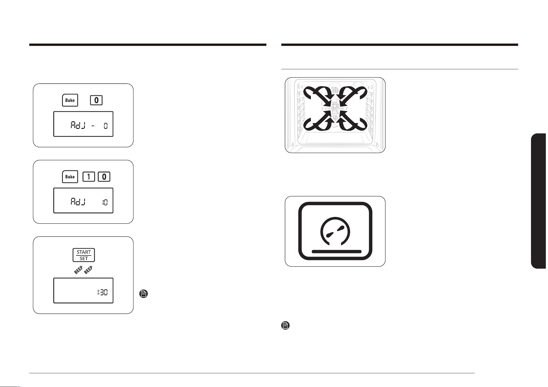
Français 39
Utilisation du four
Cuisson et rôtissage par convection
La fonction Convection Bake (Cuisson par
convection), vous permet de programmer la cuisson
du four à une température comprise entre 66 °C
(150 °F) et 288 °C (550 °F). La fonction Convection
Roast (Rôtissage par convection), vous permet
de programmer le rôtissage à une température
comprise entre 66 °C (150 °F) et 288 °C (550 °F).
Le ventilateur de convection, situés au fond du
four, font circuler l'air chaud uniformément dans
le four. En conséquence, les aliments sont cuits
uniformément et doré en moins de temps qu'avec
une chaleur normale.
Cuisson par convection
• Idéale pour la cuisson de plusieurs aliments sur
différentes grilles.
• Pratique pour des grosses quantités d'aliments
cuits.
• Apporte de bons résultats avec les cookies, les
biscuits, les brownies, les cupcakes, les choux à la
crème, les viennoiseries, les gâteaux des anges et
le pain.
• Les cookies cuisent mieux sur des feuilles à
cookies plates.
• Si vous utilisez la cuisson par convection sur une
seule grille, placez-la sur la position 3 ou 4. Si vous
utilisez la cuisson par convection sur plusieurs
grilles, placez-les sur les positions 2 et 5.
Remarque
Le four règle automatiquement la température de cuisson par convection avec le programme
Convection Auto Conversion (Convection par conversion automatique). Voir page 57 pour plus
d’informations.
Si les résultats de cuisson ne sont pas ceux attendus, la température de
cuisson préréglée peut être ajustée à + ou - 15 °C (30 °F), comme suit :
1. Maintenez les touches Bake (Cuisson
traditionnelle) et 0 enfoncées pendant
3 secondes.
L'écran afche AdJ et 0.
2. Appuyez sur la touche Bake (Cuisson
traditionnelle) pour alterner entre les
réglages de température + ou -.
3. Appuyez sur les touches du pavé
numérique pour saisir l’ajustement de la
température souhaitée
(par exemple 1, 0).
L'écran afche AdJ et 10.
4. Appuyez sur la touche START/SET
(DÉPART/RÉGLAGE).
Un signal sonore retentit deux fois
et l'écran afche l'heure actuelle. À la
prochaine cuisson, le four utilisera le
nouveau réglage de température.
Remarque
Ce réglage n’affecte en rien les
températures de la cuisson au gril ou du
cycle d’auto-nettoyage. Le réglage sera
conservé en mémoire même après une
coupure de courant.
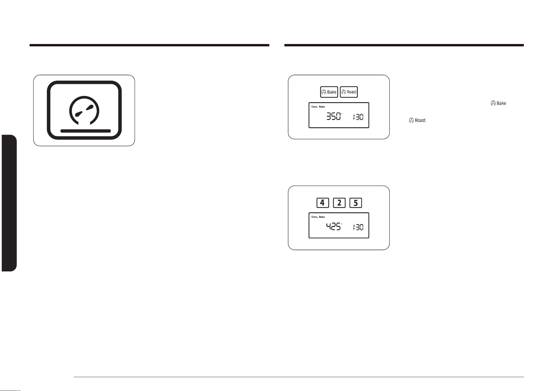
40 Français
Utilisation du four
Utilisation du four
Comment régler le four pour la cuisson ou le rôtissage par convection ?
1. Positionnez la grille sur l'emplacement
de votre choix.
2. Appuyez sur la touche Convection
Bake (Cuire par convection) ( ) ou
Convection Roast (Rôtir par convection)
( ),. Un signal sonore retentit à
chaque fois que vous appuyez sur une
touche.
La température par défaut (350°)
clignote à l'écran. Si la température par
défaut est celle que vous désirez, passez
à l'étape 4.
3. Appuyez sur les touches du pavé
numérique pour saisir la température de
cuisson souhaitée (par exemple 4, 2, 5).
La température de cuisson choisie
clignote à l'écran.
Rôtissage par convection
• Pratique pour les gros morceaux de
viande, non couvert.
• Placez la lèchefrite et la grille sous
la viande ou la volaille pendant le
rôtissage par convection pour de
meilleurs résultats. La lèchefrite
récupère les éclaboussures de graisse
tandis que la grille sert à les éviter.
La viande et la volaille sont dorées de toute part, comme après une cuisson en
rôtissoire. L'air chaud circule au-dessus, en-dessous, et autour de la nourriture en
cours de rôtissage. L'air chauffé se mélange rapidement au jus pour une cuisson
moelleuse et tendre du morceau tout en dorant parfaitement l'extérieur.
Voir le Guide de rôtissage par convection page 41, pour les recommandations sur
les temps de cuisson et les températures.
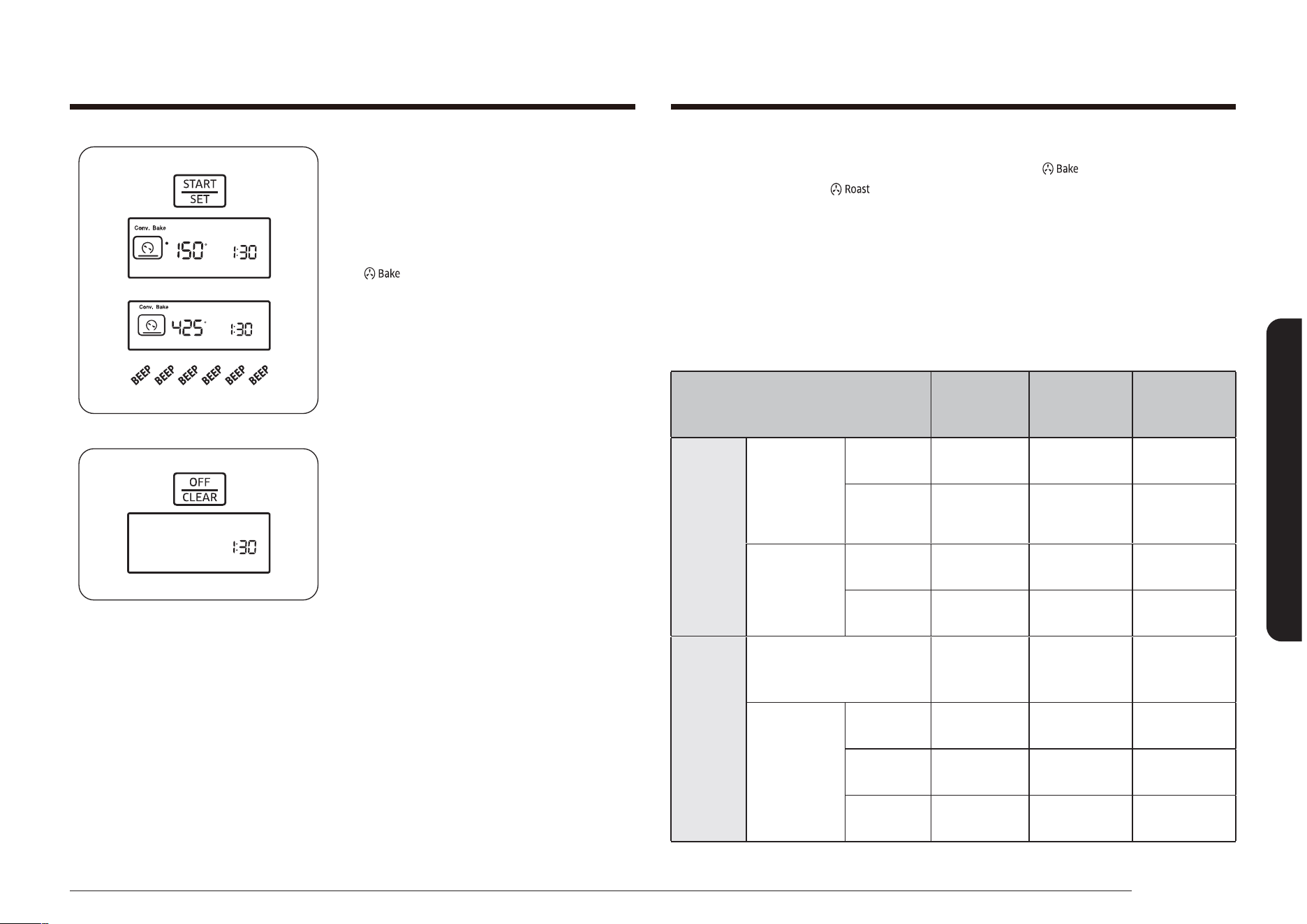
Français 41
Utilisation du four
4. Appuyez sur la touche START/SET
(DÉPART/RÉGLAGE).
Le four s'allume automatiquement et le
préchauffage démarre. L'écran afche
un « • » clignotant, ainsi que 150° et
Conv. Bake (Cuisson par convection)
( ), et les symboles de cette cuisson
et de la ventilation, jusqu'à ce que le
four atteigne cette température. Ensuite,
l'écran n'afche que la température
actuelle du four.
Lorsque le four atteint la température
de cuisson ou de rôtissage souhaitée, un
signal sonore retentit 6 fois.
5. Placez les aliments dans le four, puis
fermez la porte.
Le préchauffage est très important
pour une bonne cuisson. Il est conseillé
d'utiliser la lèchefrite et la grille pour un
rôtissage.
6. Une fois la cuisson ou le rôtissage
terminé, sortez les aliments du four,
fermez la porte, et appuyez sur la
touche OFF/CLEAR (ARRÊT/EFFACER).
Le four s'éteint et l'écran afche l'heure
du jour.
Pour changer une température de cuisson ou de rôtissage programmée, appuyez
sur la touche Convection Bake (Cuire par convection) ( ) ou Convection Roast
(Rôtir par convection) ( ), entrez la nouvelle température, puis appuyez sur la
touche START/SET (DÉPART/RÉGLAGE). Si la température du four est inférieure au
nouveau réglage, un signal sonore retentit 6 fois, puis afche les données entrées.
Le four termine la cuisson avec la nouvelle température.
Guide de rôtissage par convection
Les temps de rôtissage dépendent de la taille, du poids, de l'épaisseur, du réglage
de la température de rôtissage ainsi que de vos préférences de cuisson.
Le guide suivant est basé sur des aliments sortant du réfrigérateur.
Type d'aliment
Minutes
par kilos
(livres)
Température
du four
Température
interne
Bœuf
Côte de
porc
(1,4 à
2,2 kg)
(3 à 5 lb)
Medium
(Moyen)
28–33
177 °C
(350 °F)
71 °C
(160 °F)
Bien cuit 30–38
177 °C
(350 °F)
77 °C
(170 °F)
Filet
(1 à 1,4 kg)
(2 à 3 lb)
Medium
(Moyen)
35–45
177 °C
(350 °F)
71 °C
(160 °F)
Bien cuit 45–55
177 °C
(350 °F)
77 °C
(170 °F)
Porc
Rôti
(avec ou sans os)
(1,4 à 2,2 kg) (3 à 5 lb)
22–28
177 °C
(350 °F)
77 °C
(170 °F)
Côtelettes
(1,3 à
2,5 cm
d'épaisseur)
(0,5 à 1”)
2
côtelettes
30 à 40 min
au total
177 °C
(350 °F)
77 °C
(170 °F)
4
côtelettes
40 à 50 min
au total
177 °C
(350 °F)
77 °C
(170 °F)
6
côtelettes
45 à 55 min
au total
177 °C
(350 °F)
77 °C
(170 °F)
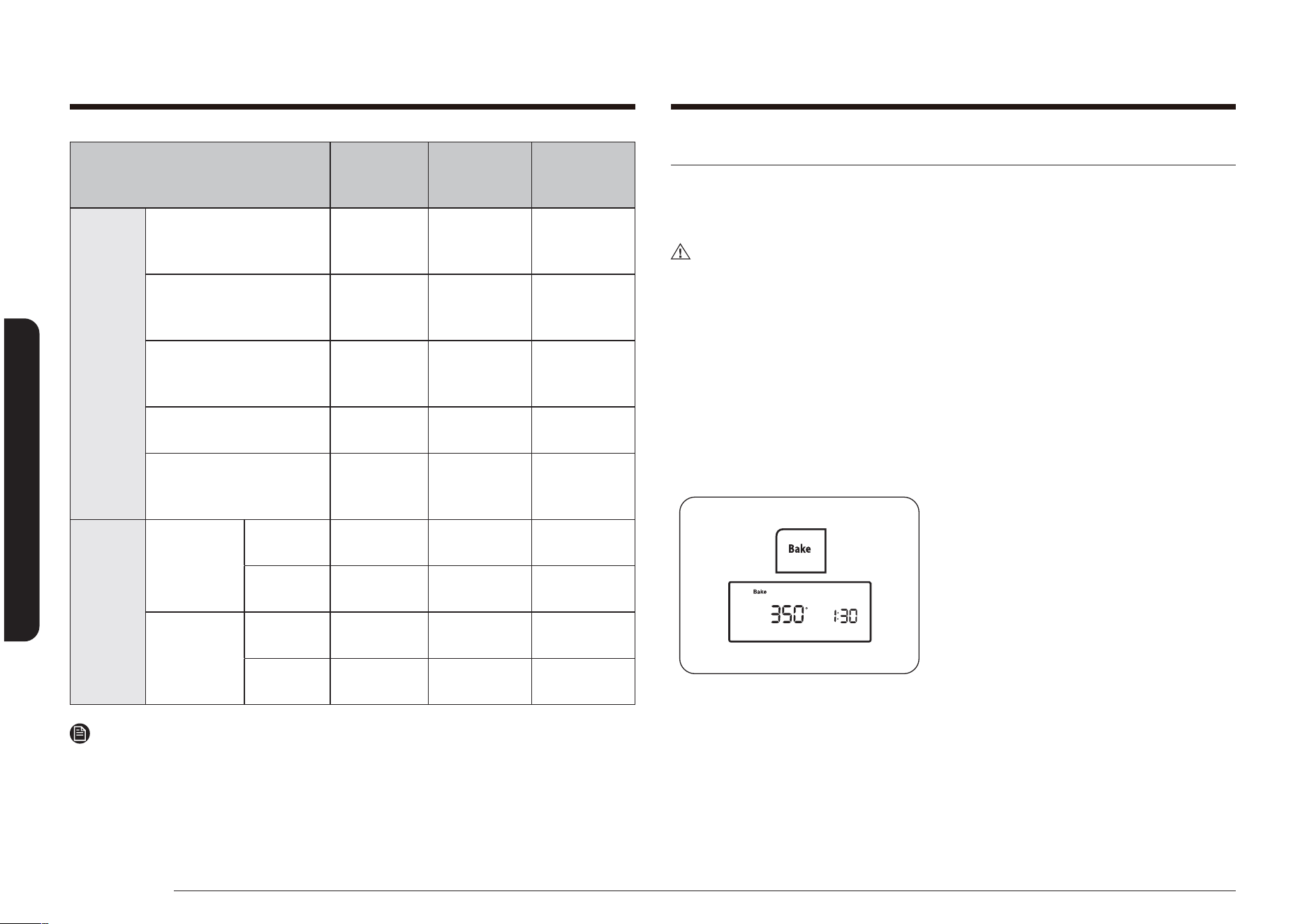
42 Français
Utilisation du four
Utilisation du four
Cuisson minutée
La fonction Cook Time (Temps de cuisson) vous permet de programmer une
température de cuisson pour une durée déterminée. À la n du temps programmé,
le four s'éteint automatiquement.
ATTENTION
Soyez prudent lorsque vous utilisez les fonctions Cook Time (Temps de cuisson)
ou Delay start (Départ différé). Ces fonctions sont très utiles pour la cuisson
des viandes salées ou surgelées ainsi que de la plupart des fruits et légumes.
Les aliments qui se périment facilement, comme le lait, les oeufs et les viandes,
doivent être conservés au réfrigérateur avant d'être placés dans le four. Même
réfrigérés, ces aliments ne doivent pas rester à l'air ambiant pendant plus
d'une heure avant le démarrage de la cuisson. De plus, ils doivent être retirés
rapidement du four une fois la cuisson terminée. La consommation d'aliments
gâtés peut entraîner des maladies liées à un empoisonnement alimentaire.
Comment régler le four pour la cuisson minutée ?
1. Positionnez la grille du four sur
l’emplacement de votre choix. Placez
les aliments dans le four, puis fermez la
porte.
2. Appuyez sur le bouton Bake (Cuisson
traditionnelle).
La température par défaut (350°)
clignote à l'écran. Si la température par
défaut est celle que vous désirez, passez
à l'étape 4.
Type d'aliment
Minutes
par kilos
(livres)
Température
du four
Température
interne
Volaille
Poulet entier
(1,1 à 1,5 kg)
(2,5 à 3,5 lb)
26–30
191 °C
(375 °F)
82 °C
(180 °F)
Dinde entière
(non fourrée *)
(8 à 11 kg) (10 à 16 lb)
10–16
163 °C
(325 °F)
82 °C
(180 °F)
Dinde entière
(non fourrée *)
(8 à 11 kg) (18 à 24 lb)
8–15
163 °C
(325 °F)
82 °C
(180 °F)
Blancs de dinde
(1,8 à 2,7 kg) (4 à 6 lb)
18–23
163 °C
(325 °F)
77 °C
(170 °F)
Poulet de Cornouailles
(400 à 700 g)
(1 à 1,5 lb)
50 à 75 min
au total
163 °C
(325 °F)
82 °C
(180 °F)
Agneau
Demi-gigot
(1,4 à
1,8 kg)
(3 à 4 lb)
Medium
(Moyen)
25–30
163 °C
(325 °F)
71 °C
(160 °F)
Bien cuit 30–35
163 °C
(325 °F)
77 °C
(170 °F)
Gigot entier
(2,7 à
3,2 kg)
(6 à 7 lb)
Medium
(Moyen)
25–30
163 °C
(325 °F)
71 °C
(160 °F)
Bien cuit 30–35
163 °C
(325 °F)
77 °C
(170 °F)
Remarque
* Une dinde farcie nécessite un temps de cuisson supplémentaire. La température
minimale nécessaire pour cuire la farce dans la volaille est de 74 °C (165 °F).

Français 43
Utilisation du four
6. Appuyez sur la touche START/SET
(DÉPART/RÉGLAGE).
Le four s'éclaire automatiquement et
commence le préchauffage. L'écran
afche un « • » clignotant, ainsi que la
température par défaut, ou la température
choisie, Bake (Cuisson traditionnelle) et le
symbole du mode de cuisson, jusqu'à ce
que le four atteigne cette température.
Lorsque le four atteint la température
désirée, le signal sonore retentit 6 fois. Le
four commence la cuisson pour la durée
dénie et le temps restant s'afche.
Pour voir l'heure, maintenez la touche
Clock (Horloge) enfoncée. Lorsque vous
relâchez la touche Clock (Horloge),
l'afchage se réinitialise et le temps
de cuisson restant s'afche à nouveau.
Lorsque le temps de cuisson est écoulé, le
four s'éteint automatiquement et l'écran
afche l'heure actuelle.
Pour changer une température de cuisson programmée, appuyez sur la touche
Bake (Cuisson traditionnelle), entrez la nouvelle température, puis appuyez sur la
touche START/SET (DÉPART/RÉGLAGE). Si la température du four est inférieure au
nouveau réglage, un signal sonore retentit 6 fois, puis afche les données entrées.
Le four termine la cuisson avec la nouvelle température.
Pour changer un temps de cuisson programmé, appuyez sur la touche Cooking
Time (Temps de cuisson), entrez le nouveau temps de cuisson, puis appuyez sur la
touche START/SET (DÉPART/RÉGLAGE). Le four continue la cuisson pour le temps
restant du nouveau réglage.
Remarque
Si la recette l'indique, enfournez la nourriture une fois le four préchauffé. Le
préchauffage est important pour une bonne cuisson. Lorsque le four atteint la
température souhaitée, un signal sonore retentit 6 fois.
3. Appuyez sur les touches du pavé
numérique pour saisir la température de
cuisson souhaitée (par exemple 3, 7, 5).
La température de cuisson choisie
clignote à l'écran.
4. Appuyez sur la touche Cooking Time
(Temps de cuisson).
L'écran afche -
hr
--
min
.
(les caractères hr, min ne s’affchent pas
sur le modèle NX58*560***, NX58*751***)
5. Appuyez sur les touches du pavé
numérique pour saisir le temps de
cuisson souhaité.
L’écran afche le temps choisi, et le
voyant Start (Démarrage) clignote. Vous
pouvez régler le temps sur n’importe
quelle durée comprise entre 1 minute et
9 heures et 99 minutes.
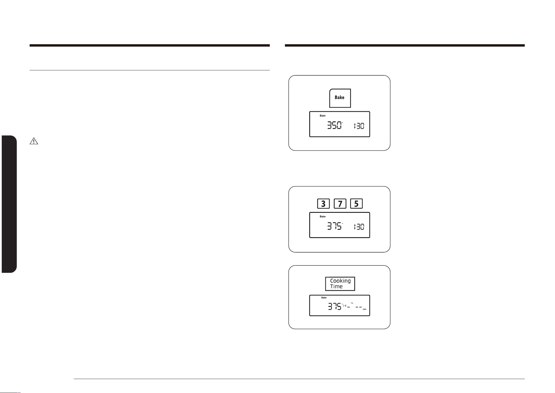
44 Français
Utilisation du four
Utilisation du four
Comment régler le four pour la cuisson minutée différée ?
1. Positionnez la grille du four sur
l’emplacement de votre choix. Placez
les aliments dans le four, puis fermez la
porte.
2. Appuyez sur la touche du mode de
cuisson souhaité (ex : Bake (Cuisson
traditionnelle).
La température par défaut (350°) et
l'indicateur Start (Démarrer) clignotent à
l'écran. Si la température par défaut est
celle que vous désirez, passez à l'étape
4.
3. Appuyez sur les touches du pavé
numérique pour saisir la température de
cuisson souhaitée (par exemple 3, 7, 5).
La température de cuisson et l'indicateur
Start (Démarrer) clignotent à l'écran.
4. Appuyez sur la touche Cooking Time
(Temps de cuisson).
L'écran afche la température de
cuisson sélectionnée, Bake (Cuisson
traditionnelle) et -
hr
--
min
.
(les caractères HR, min ne s'afchent pas
sur le modèle NX58*560***, NX58*751***)
Cuisson minutée différée
La fonction Delay Start (Départ différé) vous permet d’utiliser la minuterie pour
commencer et arrêter automatiquement un autre programme de cuisson (Bake
(Cuisson traditionnelle), Convection Bake (Cuisson par convection), ou Convection
Roast (Rôtissage par convection)). La fonction Delay Start (Départ différé) peut
être réglée jusqu’à 12 heures avant d’autres cuissons. L’horloge doit être réglée
à la bonne heure pour que la fonction Delay Start (Départ différé) fonctionne
correctement.
ATTENTION
Soyez prudent lorsque vous utilisez les fonctions Cook Time (Temps de cuisson)
ou Delay start (Départ différé). Ces fonctions sont très utiles pour la cuisson
des viandes salées ou surgelées ainsi que de la plupart des fruits et légumes.
Les aliments qui se périment facilement, comme le lait, les oeufs et les viandes,
doivent être conservés au réfrigérateur avant d'être placés dans le four. Même
réfrigérés, ces aliments ne doivent pas rester à l'air ambiant pendant plus
d'une heure avant le démarrage de la cuisson. De plus, ils doivent être retirés
rapidement du four une fois la cuisson terminée. La consommation d'aliments
gâtés peut entraîner des maladies liées à un empoisonnement alimentaire.
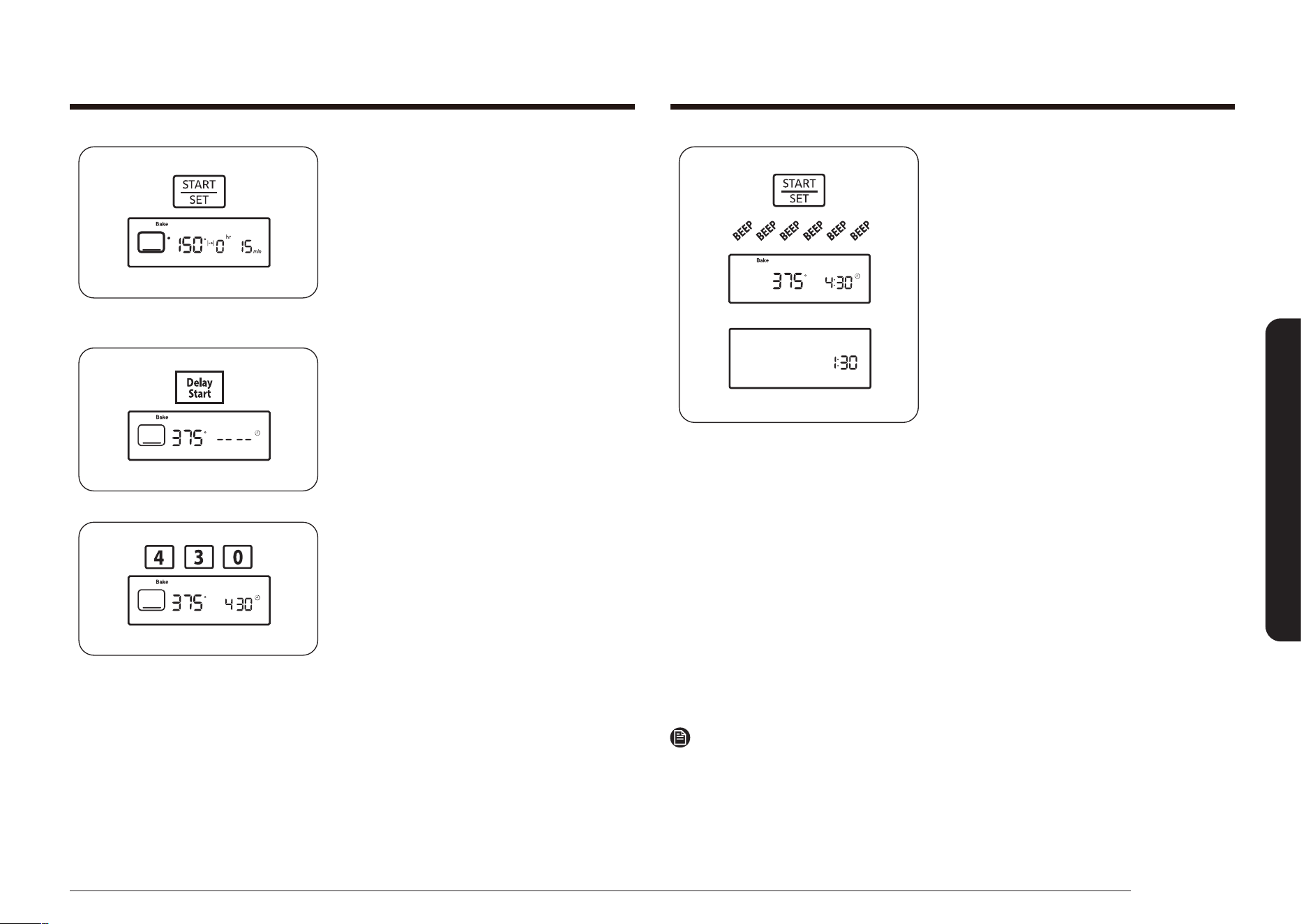
Français 45
Utilisation du four
8. Appuyez sur la touche START/SET
(DÉPART/RÉGLAGE).
Le four s'allume automatiquement et
un signal sonore retentit à l'heure de
départ.
Le four s'allume automatiquement et
le préchauffage démarre. Lorsque le
four atteint la température de cuisson
souhaitée, un signal sonore retentit 6
fois.
Le décompte du temps de cuisson
s’afche.
Lorsque le temps de cuisson est écoulé,
le four s'éteint automatiquement et
l'écran afche l'heure actuelle.
Pour changer une heure de départ programmée, appuyez sur la touche Delay Start
(Départ différé), entrez la nouvelle heure, puis appuyez sur la touche START/SET
(DÉPART/RÉGLAGE). Le four commence la cuisson à la nouvelle heure.
Pour changer une température de cuisson programmée, appuyez sur la touche
Bake (Cuisson traditionnelle), entrez la nouvelle température, puis appuyez sur la
touche START/SET (DÉPART/RÉGLAGE). Si la température du four est inférieure au
nouveau réglage, un signal sonore retentit 6 fois, puis afche les données entrées.
Le four termine la cuisson avec la nouvelle température.
Pour changer un temps de cuisson programmé, appuyez sur la touche Cooking
Time (Temps de cuisson), entrez le nouveau temps de cuisson, puis appuyez sur la
touche START/SET (DÉPART/RÉGLAGE). Le four continue la cuisson pour le temps
restant du nouveau réglage.
Remarque
Si la recette l'indique, enfournez la nourriture une fois le four préchauffé. Le
préchauffage est important pour une bonne cuisson. Lorsque le four atteint la
température souhaitée, un signal sonore retentit 6 fois.
5. Appuyez sur les touches du pavé
numérique pour saisir le temps de
cuisson souhaité.
L'écran afche le temps de cuisson
sélectionné, et le symbole Start
(Démarrage) clignote. Vous pouvez
régler le temps de cuisson pour une
durée comprise entre 1 minute et
9 heures 99 minutes.
6. Appuyez sur la touche Delay Start
(Départ différé).
L'écran afche Delay (Retard) et -- --
clignote.
7. Appuyez sur les touches du pavé
numérique pour saisir l’heure à laquelle
vous souhaitez que le four s’allume (par
exemple 4, 3, 0).
Le symbole Start (Démarrage) clignote
sous Delay (Retard) et l'heure de départ
choisie.
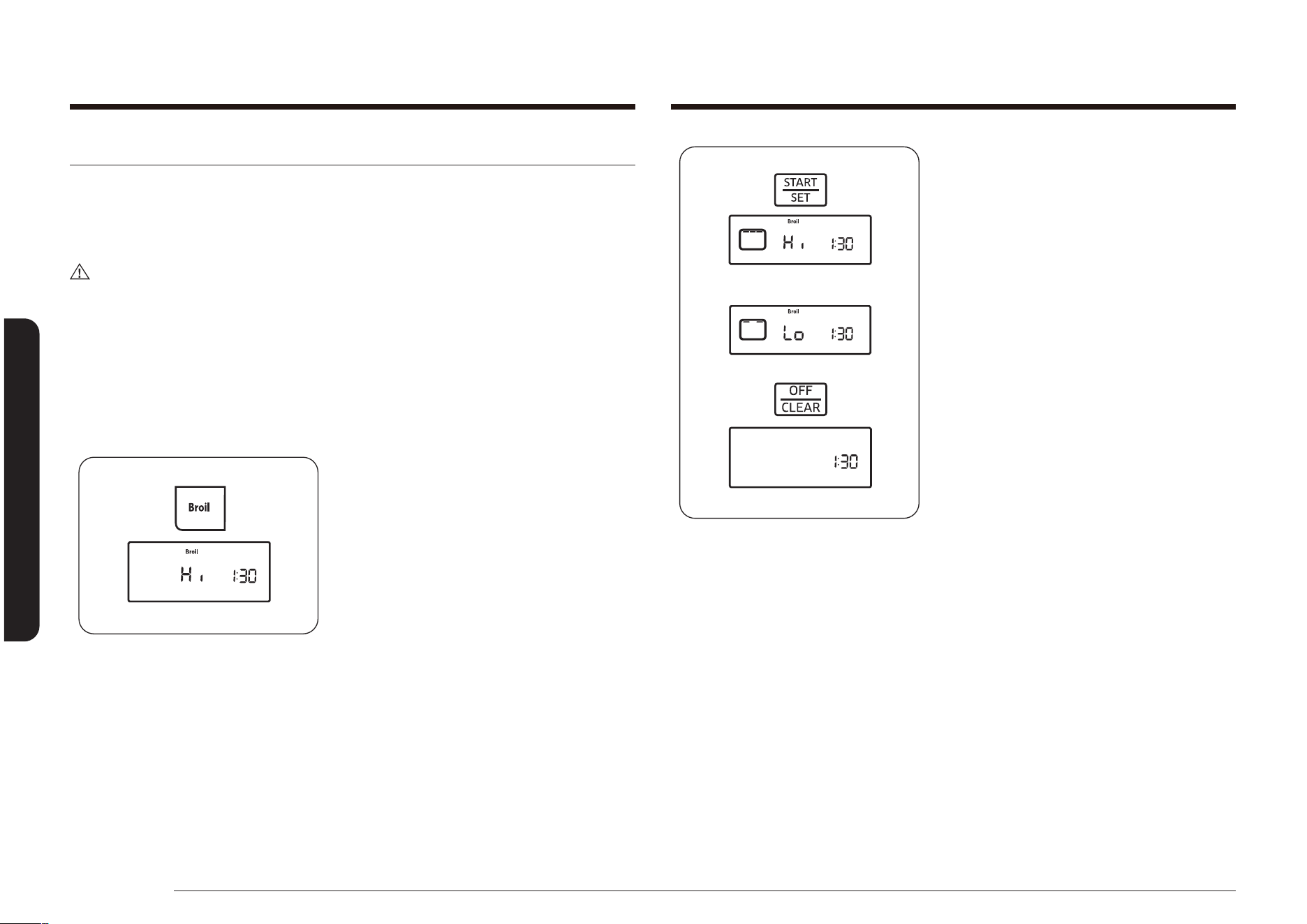
46 Français
Utilisation du four
Utilisation du four
3. Appuyez sur la touche START/SET
(DÉPART/RÉGLAGE).
Le four éclaire automatiquement la
résistance du haut et commence la
cuisson.
L'écran afche le mode de gril choisi (Hi
ou Lo), son symbole et Broil (Gril).
Faites cuire un côté des aliments au
gril jusqu'à ce qu'ils soient brunis. Puis,
tournez-les et faites cuire l'autre côté.
Une fois la cuisson terminée, appuyez
sur la touche OFF/CLEAR (ARRÊT/
EFFACER) pour éteindre le four ou
annuler la cuisson au gril à tout moment.
L'heure actuelle s'afche.
Pour modier un réglage programmé de cuisson au gril, appuyez sur la touche
Broil (Cuisson au gril) pour changer le réglage entre Hi (Élevé) et Lo (Faible).
Appuyez sur la touche START/SET (DÉMARRER/RÉGLER) pour terminer la cuisson
avec le nouveau réglage.
Cuisson au gril
La fonction Gril vous permet de cuire et dorer les aliments en utilisant uniquement
la source de chaleur supérieure. La porte du four doit rester fermée pendant la
cuisson au gril des aliments. La viande et le poisson doivent toujours être placés
sur une grille dans une lèchefrite du gril.
ATTENTION
Si des ammes apparaissent pendant la cuisson au gril, laissez la porte du four
fermée et éteignez le four. Si les ammes ne s’éteignent pas, jetez du bicarbonate
de soude sur les ammes ou utilisez un extincteur à mousse. Ne jetez ni eau
ni farine sur les ammes. La farine peut exploser et l’eau peut provoquer des
ammes de friture qui se propagent. Tous deux peuvent entraîner des blessures
corporelles et/ou des dégâts matériels.
Comment régler le four pour la cuisson au gril ?
1. Placez les aliments sur une lèchefrite à
gril avec une grille. Posez la nourriture
et la lèchefrite sur la grille du haut,
positionnez-la comme indiqué dans le
Guide de cuisson au gril à la page 47.
Fermez la porte du four.
2. Appuyez sur la touche Broil (Gril) une
fois pour sélectionner Hi (Élevé) ou deux
fois pour sélectionner Lo (Faible). Un
signal sonore retentit à chaque fois que
vous appuyez sur une touche.
Le symbole Start (Démarrage) clignote
à droite du symbole Hi (Élevé) ou Lo
(Faible) et de Broil (Gril) à l'écran.
Sélectionnez Lo (Faible) pour cuire des
aliments tels que de la volaille ou des
morceaux épais de viandes sans risquer
de trop les brunir.
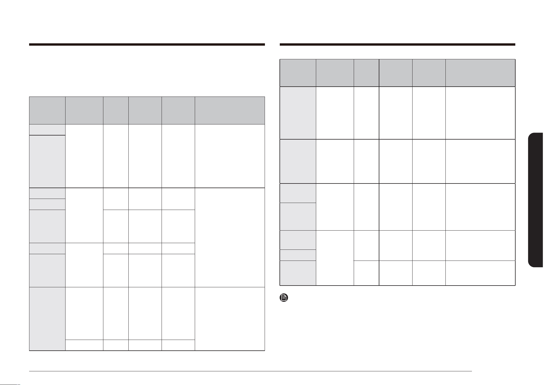
Français 47
Utilisation du four
Type
d'aliment
Quantité et/ou
épaisseur
Hauteur
de grille*
Temps pour
le 1er côté
(en min)
Temps pour
le 2ème côté
(en min)
Remarques
Filets de
poisson
0,6 à 1,3 cm
(0,25 à 0,5”)
d'épaisseur
6 6-10 3-4
Manipulez et retournez avec
précaution.
Selon vos goûts, vous
pouvez badigeonner de
beurre citronné avant et
pendant la cuisson.
Tranches de
jambon
(précuits)
1,3 cm (0,5”)
d'épaisseur
6 7-10 5-6
Augmentez le temps (10
minutes au lieu de 5) pour
chaque côté pour du jambon
de 0,7 cm (1,5”) d'épaisseur
ou artisanal.
Côtelettes de
porc
Bien cuit
2 (1,3 cm
(0,5”)
d'épaisseur)
6 8-11 4-6
Incisez pour extraire la
graisse.
Côtelettes
d'agneau
Moyen 2 (2,5 cm (1”)
d'épaisseur)
environ 10 à
12 oz.
6 8-12 5-8 -
Bien cuit 6 10-16 7-11
Incisez pour extraire la
graisse.
Remarque
* Voir illustration page 35 pour la description des hauteurs de grille.
Guide de cuisson au gril
Les temps de cuisson au gril dépendent de la taille, du poids, de l'épaisseur, du
réglage de la température de gril ainsi que de vos préférences de cuisson. Le guide
suivant est basé sur des viandes et/ou des poissons sortant du réfrigérateur.
Type
d'aliment
Quantité et/ou
épaisseur
Hauteur
de grille*
Temps pour
le 1er côté
(en min)
Temps pour
le 2ème côté
(en min)
Remarques
Bœuf haché
Bien cuit
500 g (1 lb)
soient 4
boulettes de
1,2 à 1,9 cm
d'épaisseur
(0,5 à 0,75”)
6 ou 7 7-10 5-7
Répartissez uniformément.
Vous pouvez cuire jusqu'à
8 boulettes simultanément.
Biftecks
Moyen 900 à 1300 g
(1 à 1,5 lbs)
de 3,8 cm
d'épaisseur
(1”)
6 10-12 5-7
Les biftecks dont l'épaisseur
ne dépasse pas 1,2 cm (1”)
cuisent avant de brunir.
Il est conseillé de les frire
sur le gril.
Incisez pour extraire la
graisse.
Bien cuit 6 12-14 6-8
Moyen 900 à 1300 g
(2 à 2,5 lbs)
de 3,8 cm
d'épaisseur
(1,5”)
6 15-18 14-17
Bien cuit 6 18-22 17-19
Poulet
1 poulet
entier, de
900 à 1300 g
(2 à 2,5 lbs),
coupé dans la
longueur
4 30-35 15-20
Grillez d'abord le côté peau
vers le bas.
Ouvrez en écartant.
Badigeonnez de beurre
fondu avant de griller et à
mi-cuisson.
2 blancs 5 15-20 7-12
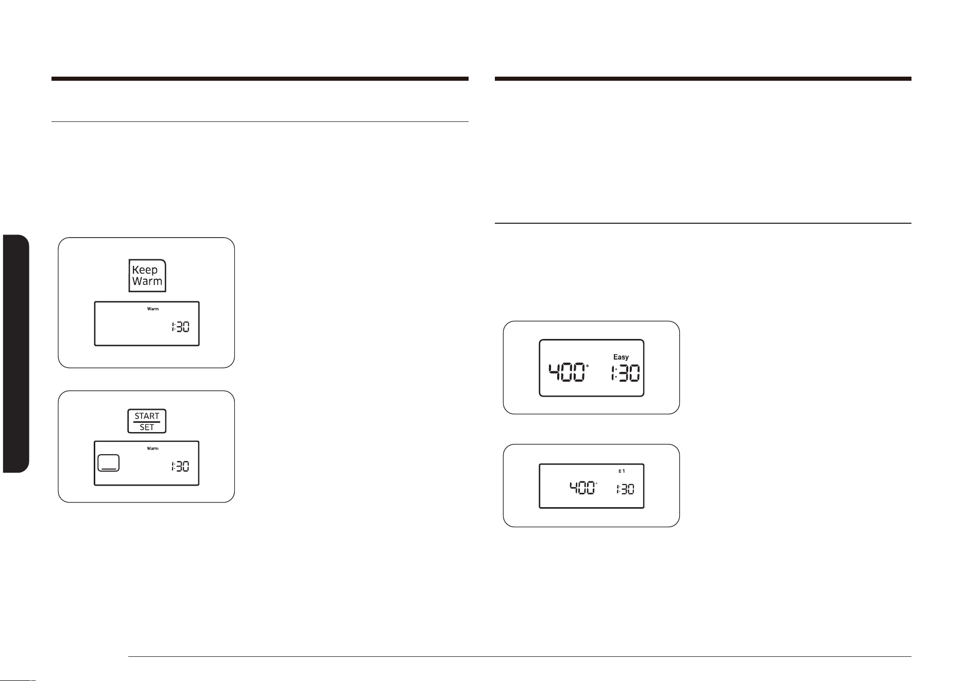
48 Français
Utilisation du four
Utilisation du four
Pour programmer un maintien au chaud après une fonction de cuisson minutée,
appuyez sur la touche Keep Warm (Maintien au chaud) après avoir programmé
la fonction de cuisson minutée. Une fois la cuisson terminée, un signal sonore
retentit 6 fois et la température du four baisse pour atteindre celle du programme
de maintien au chaud. Le four conserve cette température jusqu'à ce que le mode
Keep Warm (Maintien au chaud) soit annulé.
Utilisation de la fonction Cuisson facile
Pizza
La fonction Pizza (Pizza) est conçue pour dorer et donner du croustillant à la pâte
tout en conservant le moelleux de la garniture.
Comment régler la fonction Pizza ?
NX58*560***, NX58*751***
NX58*565***
1. Appuyez sur la touche Pizza.
Maintien au chaud
La fonction Keep Warm (Maintien au chaud) vous permet de conserver des
aliments cuits au chaud à une basse température de cuisson. La fonction Keep
Warm (Maintien au chaud) permet de conserver des aliments cuits au chaud
jusqu'à 3 heures après leur cuisson en vue de les servir. Au bout de 3 heures, le
four s'éteint automatiquement.
Comment utiliser la fonction de maintien au chaud ?
1. Positionnez la grille sur l'emplacement
de votre choix. Placez les aliments dans
le four et fermez la porte.
2. Appuyez sur la touche Keep Warm
(Maintien au chaud).
Le voyant Start (Démarrage) clignote
en dessous de l’heure actuelle et Warm
(Chaud) apparaît à l’écran.
3. Appuyez sur la touche START/SET
(DÉPART/RÉGLAGE).
Le four s'éclaire automatiquement
et commence le préchauffage de la
température Keep Warm (Maintien au
chaud (environ 77 °C [170 °F]). L'écran
afche le symbole du four, Warm
(Chaud), et l'heure.
Pour annuler la fonction Keep Warm
(Maintien au chaud) et éteindre le four,
appuyez sur la touche OFF/CLEAR
(ARRÊT/EFFACER). L’heure actuelle
s’afche.
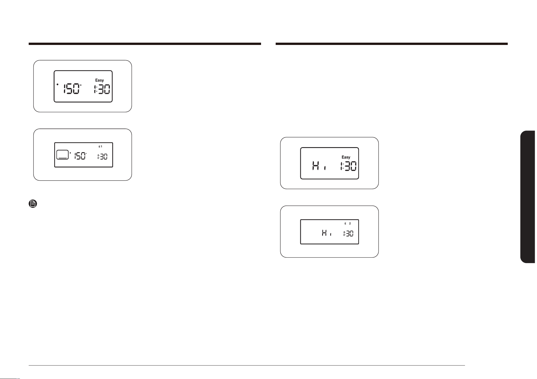
Français 49
Utilisation du four
Cuisson lente
La fonction Slow Cook (Cuisson lente) peut être utilisée pour cuire les aliments plus
lentement à une température plus basse. Un temps de cuisson plus long permet
une meilleure diffusion des arômes dans de nombreuses recettes. Cette fonction
est idéale pour faire rôtir du bœuf, du porc et de la volaille. La cuisson lente de la
viande peut lui donner un aspect foncé sur le dessus sans qu’elle soit brûlée. Ceci
est tout à fait normal.
Comment régler la fonction Cuisson lente ?
NX58*560***, NX58*751***
NX58*565***
1. Appuyez sur la touche SLOW COOK
(CUISSON LENTE) une fois pour
sélectionner HI (ÉLEVÉ) ou deux fois
pour sélectionner LO (FAIBLE).
NX58*560***, NX58*751***
NX58*565***
2. Appuyez sur le bouton START/SET
(DÉPART/RÉGLAGE) pour lancer la
cuisson de la pizza.
Remarque
• Utilisez une seule grille et placez-la sur la position 3 ou 4 pour obtenir les
meilleurs résultats lors de l'utilisation de la fonction Pizza.
• La température par défaut est de 400 °F. Vous pouvez régler la température du
four selon vos besoins.
• Suivez les instructions gurant sur l’emballage pour connaître les temps de
préchauffage et de cuisson.
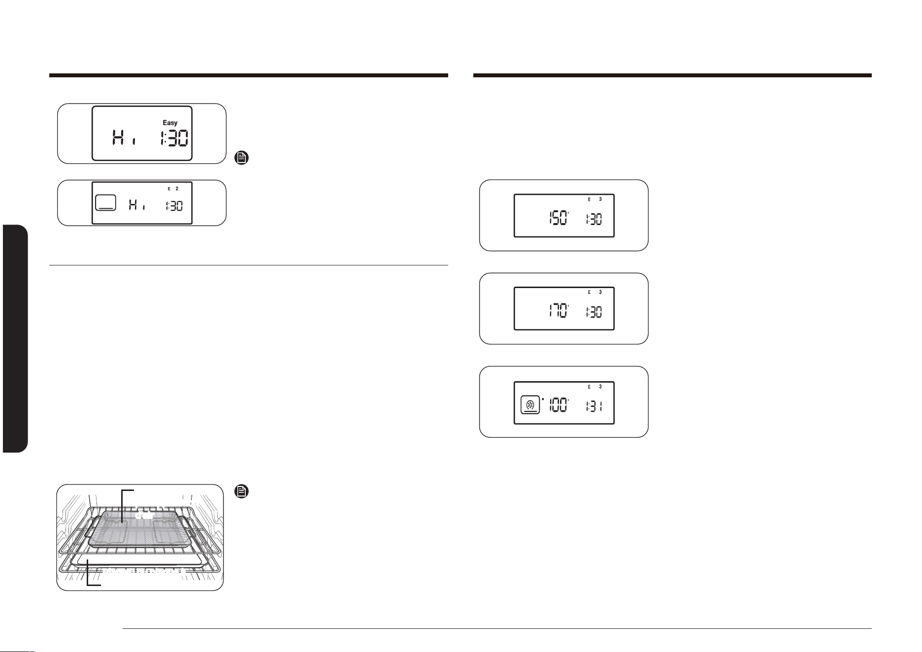
50 Français
Utilisation du four
Utilisation du four
Déshydratation des aliments
Cette fonction permet de faire sécher des aliments an d’en retirer l’eau à l’aide de
la chaleur tournante.
Comment régler la fonction Dehydrate (Déshydrater)
1. Appuyez sur la touche Dehydrate
(Déshydrater).
2. Appuyez sur les touches numériques
pour régler la température souhaitée
(entre 100 et 175 °F).
3. Appuyez sur le bouton START/SET
(DÉPART/RÉGLAGE) pour lancer la
déshydratation.
NX58*560***, NX58*751***
NX58*565***
2. Appuyez sur la touche START/SET
(DÉPART/RÉGLAGE) pour lancer la
cuisson lente.
Remarque
• Utilisez une seule grille et placez-la
sur la position 3 ou 4 pour obtenir de
meilleurs résultats.
• Le préchauffage du four n'est pas
nécessaire.
Mode friture par application d'air (MODÈLE NX58*751***)
Cette fonction utilise l'air chaud pour permettre d'obtenir des aliments frais ou surgelés plus
croustillants et sains, sans ou avec moins d'huile que les modes de cuisson par convection
normaux. Pour des résultats optimaux, utilisez ce mode avec le mode unique et placez le plateau
de friture par application d'air au niveau 3. La température peut être réglée entre 350 °F et
500 °F. Le préchauffage n'est pas nécessaire pour ce mode. Suivez la recette ou les indications
gurant sur l'emballage pour régler la température, la durée et la quantité.
Comment régler le four pour la cuisson en mode Friture par application d'air
1. Placez le plateau sur la position de grille 4.
2. Sélectionnez le mode Friture par application d'air à l'aide du touche tactile.
3. Utilisez la touche tactile pour modier la température par défaut. Saisissez la température
suggérée pour vos aliments, comme recommandé dans leurs indications de cuisson. La
température par défaut est de 425 °F.
4. A
ppuyez sur la touche tactile et, si nécessaire, réglez la fonction Temps de cuisson ou Départ différé.
5. Appuyez sur le bouton START/SET (DÉPART/RÉGLAGE) pour lancer le mode Friture
par application d'air.
6. U
ne fois la cuisson terminée, appuyez sur OFF/CLEAR (ARRÊT/EFFACER), puis sortez les aliments.
Plateau ou plaque à
pâtisserie
Plaque de friture
par application
d'air
Positionnement recommandé du
plateau de friture par application d'air
REMARQUE
• Placez une plaque de cuisson ou un plateau
sous le plateau de friture par application d'air
pour récupérer les égouttures. Cela permet
d'éviter les éclaboussures et la fumée.
• La friture par application d'air est conçue
pour la cuisson sur une seule grille. Placez les
aliments sur la position de grille 4 pour des
résultats optimaux.
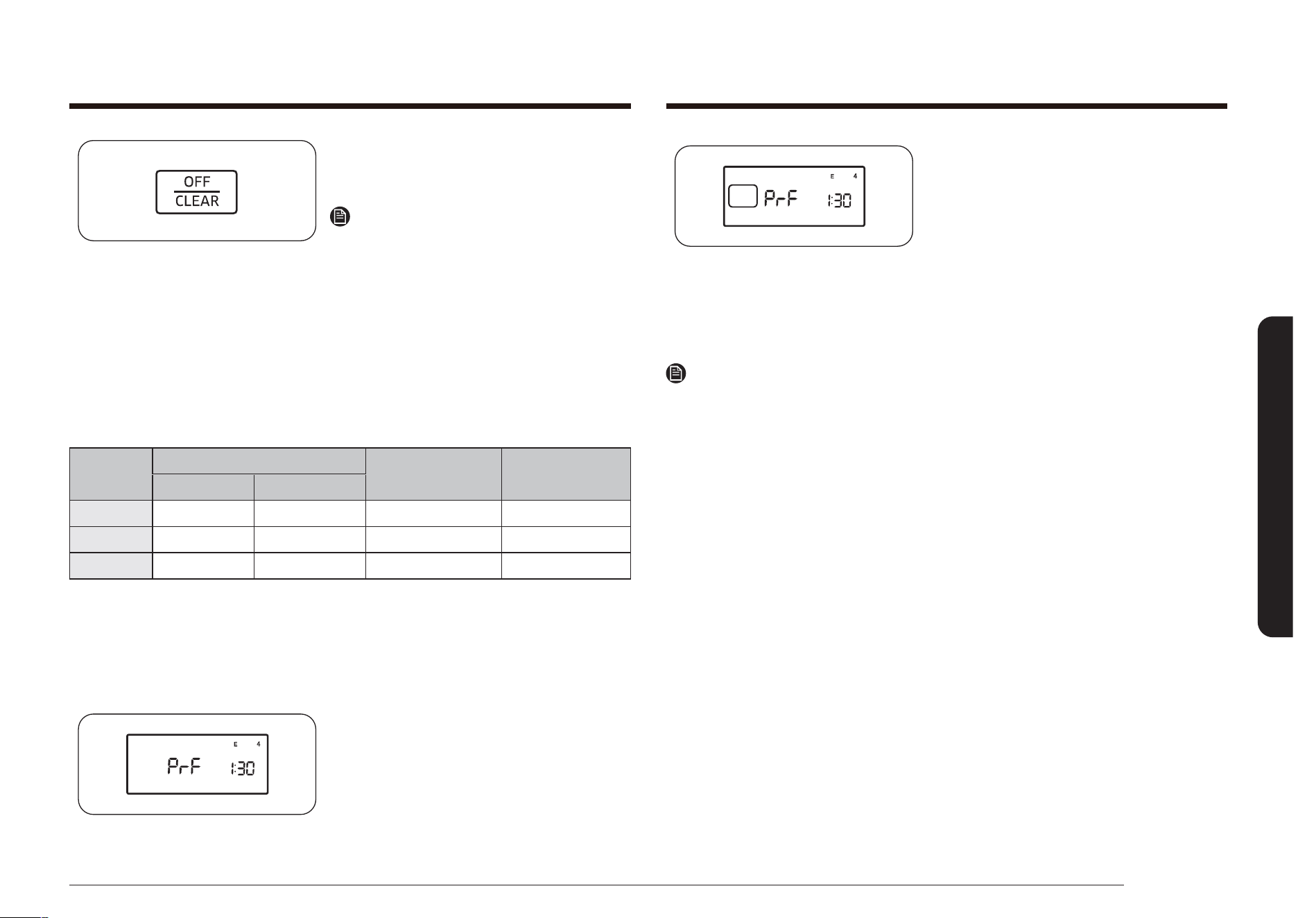
Français 51
Utilisation du four
2. Démarrez la fonction Levée. Appuyez
sur la touche. La fonction de levée
fournit automatiquement la température
optimale pour le processus de levée.
Par conséquent, aucun réglage de
température n’est nécessaire.
3. Appuyez sur la touche OFF/CLEAR
(ARRÊT/EFFACER) dès que vous
souhaitez désactiver la fonction de
levée.
Remarque
• Si vous appuyez sur la touche BREAD PROOF (LEVÉE) alors que la température
du four est supérieure à 37,7 °C (100 °F), l’indication Hot (Chaud) s’afche. Pour
assurer des résultats optimaux, il est préférable de démarrer cette fonction
à four froid. C’est pourquoi, nous vous conseillons d’attendre que le four ait
refroidi et que l’indication Hot (Chaud) disparaisse de l’afchage.
• Pour éviter de réduire la température du four et d’augmenter le temps de
levée, n’ouvrez pas la porte du four inutilement.
• Vériez les produits pâtissiers assez rapidement pour éviter qu’ils ne gonent
excessivement.
• N’utilisez pas le mode de levée pour faire réchauffer des aliments ou les
maintenir au chaud. La température émise pour la levée n’est pas assez élevée
pour réchauffer des aliments à une température sûre. Utilisez la fonction de
maintien au chaud.
• Pour de meilleurs résultats, disposez la pâte sur un plat dans le four au
niveau 3 ou 4 et couvrez-la avec un torchon ou du lm plastique. (Le plastique
doit être xé sous le récipient, an qu’il ne soit pas soulevé par la ventilation
du four.)
4. Lorsque les aliments sont déshydratés,
appuyez à nouveau sur le bouton OFF/
CLEAR (ARRÊT/EFFACER).
Remarque
• Cette fonction ne nécessite pas de
préchauffage.
• Une fois que les aliments sont
déshydratés, conservez-les dans un
endroit frais et sec.
• Si vous sélectionnez une température
située en dehors de la plage, un
message d’erreur s’afche.
Guide de la fonction déshydratation
Catégorie
Hauteur de grille
Poids
recommandé (oz)
Temp. optimale
Grille unique Grille multiple
Légumes 3 ou 4 2 et 5 9 à 21 100 à 150 ˚F
Fruits 3 ou 4 2 et 5 9 à 21 100 à 150 ˚F
Viandes 3 ou 4 2 et 5 14 à 30 145 à 175 ˚F
Levée
La fonction Levée sert à maintenir un niveau de chaleur permettant le gonement
des produits nécessitant une fermentation à la levure.
Comment régler le four pour la levée ?
1. Entrez le mode de levée.
Appuyez sur la touche Bread Proof
(Levée).
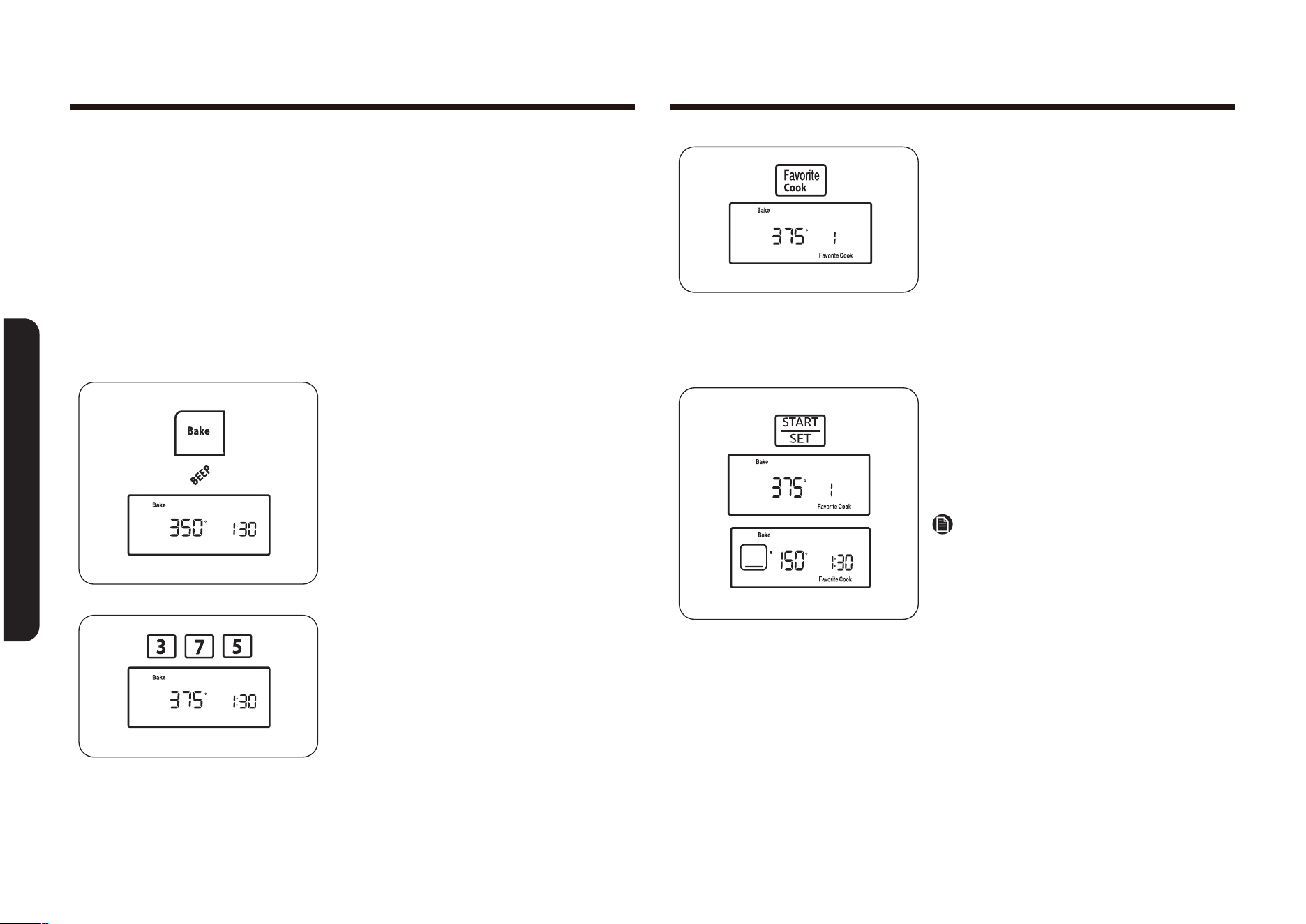
52 Français
Utilisation du four
Utilisation du four
3. Appuyez sur la touche Favorite Cook
(Cuisson personnalisée) une seule
fois pour stocker ces réglages dans
Recette 1, deux fois pour les stocker
dans Recette 2 ou trois fois pour
Recette 3.
Le numéro et le réglage correspondants
s’afchent à l’écran et Favorite Cook
(Cuisson personnalisée) clignote sous
le réglage Cuisson favorite sélectionné
pour cette recette.
4. Appuyez sur la touche START/SET
(DÉPART/RÉGLAGE).
L'écran afche la dernière température
Custom Cook (Cuisson personnalisée)
réglée ou utilisée ainsi que l'heure
actuelle.
Remarque
Appuyez sur la touche START/SET (DÉPART/
RÉGLAGE) une fois pour enregistrer
le réglage Custom Cook (Cuisson
personnalisée) ou deux fois pour enregistrer
et commencer la cuisson personnalisée sur
le réglage sélectionné.
Cuisson personnalisée
La fonction Favorite Cook (Cuisson personnalisée) vous permet de pré-programmer
3 différentes fonctions de cuisson ou les réglages de votre recette préférée qui
peuvent donc être réutilisés et lancés en actionnant un bouton. Vous pouvez
seulement utiliser les fonctions Bake (Cuisson traditionnelle), Bake convection
(Cuisson par convection) ou Roast convection (Rôtissage par convection) pour
les choix de Favorite Cook (Cuisson personnalisée). Vous ne pouvez pas utiliser
les fonctions de Delay Start (Départ différé) pour votre sélection Favorite Cook
(Cuisson personnalisée).
Comment régler une sélection de cuisson personnalisée ?
1. Appuyez sur la touche du mode de
cuisson que vous souhaitez enregistrer
(ex : Bake (Cuisson traditionnelle)). Un
signal sonore retentit à chaque fois que
vous appuyez sur une touche.
La température par défaut (350°)
clignote à l'écran. Si la température par
défaut est celle que vous désirez, passez
à l'étape 3.
2. Appuyez sur les touches du pavé
numérique pour saisir la température de
cuisson souhaitée (par exemple 3, 7, 5).
La température de cuisson choisie
clignote à l'écran.
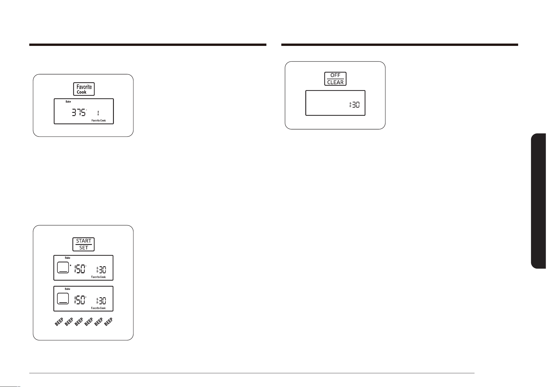
Français 53
Utilisation du four
4. Placez les aliments dans le four et
fermez la porte. Le préchauffage est très
important pour une bonne cuisson ou
bon rôtissage.
5. Une fois la cuisson terminée, sortez
les aliments du four, fermez la porte,
et appuyez sur la touche OFF/CLEAR
(ARRÊT/EFFACER).
Le four s'éteint et l'écran afche l'heure
actuelle.
Comment utiliser ou réutiliser une sélection de cuisson personnalisée ?
1. Positionnez la grille sur l'emplacement
de votre choix.
2. Appuyez sur la touche Favorite Cook
(Cuisson personnalisée). Pour rappeler le
réglage Cuisson favorite de votre choix
depuis son emplacement de stockage,
appuyez sur la touche Favorite Cook
(Cuisson personnalisée) comme indiqué
ci-dessous :
1 fois pour Recette 1,
2 fois pour Recette 2,
3 fois pour Recette 3.
Favorite Cook (Cuisson personnalisée)
clignote sous le réglage Cuisson favorite
sélectionné sur l’écran pour cette
recette.
3. Appuyez sur la touche START/SET
(DÉPART/RÉGLAGE).
« • » clignote à gauche de la
température (par défaut ou actuelle)
jusqu'à ce que la température
sélectionnée soit atteinte. Un signal
sonore retentit 6 fois. La température
par défaut ou actuelle, le mode
de cuisson, son symbole et l'heure
s'afchent.
Lorsque le four atteint la température
de cuisson souhaitée, un signal sonore
retentit 6 fois.

54 Français
Utilisation du four
Utilisation du four
4. Appuyez sur la touche START/SET
(DÉPART/RÉGLAGE).
5. Maintenez simultanément les
touches Clock (Horloge) et Timer
On/Off (Activation/Désactivation
de la minuterie) enfoncées pendant
3 secondes.
L'afchage indique alors SAb (Shabbat).
Les signaux du four, l’écran à DEL,
et toutes les commandes seront
désactivées, sauf les touches Bake
(Cuisson), Cooking Time (Temps de
cuisson), START/SET (DÉPART/RÉGLAGE)
et OFF/CLEAR (ARRÊT/EFFACER).
Dans environ 20 secondes, vous
entendrez un « clic » provenant
du tableau de commande et le four
commencera l'éclairage et le processus
de préchauffage. Lorsque le four atteint
la température de cuisson souhaitée,
le four poursuit la cuisson à cette
température jusqu'à ce que le temps de
cuisson déni se soit écoulé ou que la
fonction Sabbath (Shabbat) soit annulée.
Le décompte du temps de cuisson
ne s'afche pas, mais le four s'éteint
automatiquement à la n du temps
programmé.
Fonctionb Shabbat
K
(utilisée pour les fêtes et le Shabbat juifs)
Pour en savoir plus et obtenir des instructions d’utilisation et une liste
complète des modèles avec la fonction Shabbat, veuillez visiter le site
Web sur http:\\www.star-k.org.
La fonction Sabbath (Shabbat) ne peut être utilisée qu'avec les réglages Bake
(Cuisson traditionnelle) et Cook Time (Temps de cuisson). Le four fonctionne
sur la température dénie et ne change pas jusqu'à ce que la fonction Sabbath
(Shabbat) soit annulée ou que le temps de cuisson soit écoulé. Si la fonction
Sabbath (Shabbat) est sélectionnée, elle écrase les fonctions d'économie d'énergie
enregistrées par défaut. Tout l'éclairage de l'écran, les signaux du four, la plupart
des touches de commande et le ventilateur à convection seront désactivés.
Comment régler la fonction Sabbath ?
1. Positionnez la grille sur l'emplacement
de votre choix. Voir page 35.
2. Appuyez sur le bouton Bake (Cuisson
traditionnelle). Un signal sonore retentit
à chaque fois que vous appuyez sur
une touche jusqu'à ce que la fonction
Sabbath (Shabbat) soit activée.
La température par défaut (350°)
clignote à l'écran.
Si la température par défaut est celle
que vous désirez, passez à l'étape 4.
3. Appuyez sur les touches du pavé
numérique pour saisir la température de
cuisson souhaitée (par exemple 3, 7, 5).
La température de cuisson choisie
clignote à l'écran.
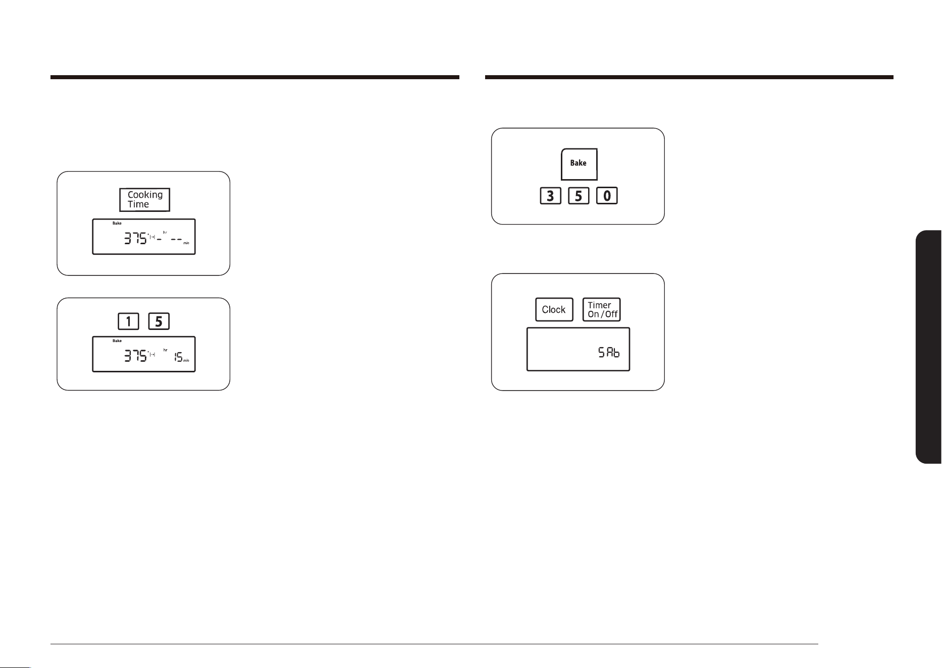
Français 55
Utilisation du four
Comment régler la fonction Shabbat ?
Pour changer une température de cuisson
programmée, appuyez sur la touche Bake
(Cuisson traditionnelle), entrez la nouvelle
température, puis appuyez sur la touche
START/SET (DÉPART/RÉGLAGE). Dans
environ 20 secondes, vous entendrez un
« clic » provenant du tableau de commande
et le four terminera la cuisson à la nouvelle
température.
Pour annuler la fonction Sabbath (Shabbat),
maintenez simultanément les touches Clock
(Horloge) et Timer On/Off (Activation/
Désactivation de la minuterie) enfoncées
pendant 3 secondes. L’heure actuelle
s’afche.
Procédure de réglage de la cuisson minutée en mode Shabbat ?
Pour régler la cuisson minutée en mode Sabbath (Sabbat), suivez les étapes 1 à
3 de la section Comment régler la fonction Sabbath ?, puis suivez les étapes ci-
dessous.
1. Appuyez sur la touche Cooking Time
(Temps de cuisson).
L'écran afche -
hr
--
min
.
(Les caractères hr et min ne s’afchent
pas sur le modèle NX58*560***,
NX58*751***.)
2. Appuyez sur les touches du pavé
numérique pour saisir le temps de
cuisson souhaité.
L'indicateur START (DÉMARRAGE)
clignote à l'écran. Vous pouvez régler
le temps de cuisson pour une durée
comprise entre 1 minute et 9 heures et
99 minutes.
Passez ensuite à l’étape 4 de la section
Comment régler la fonction Sabbath ?.

56 Français
Utilisation du four
Utilisation du four
Sélection de la température en Fahrenheit ou en Centigrade
Le four peut être programmé pour afcher la température en degrés Fahrenheit
ou Celsius.
Par défaut, le four est réglé pour que la température s'afche en degrés
Fahrenheit.
Comment passer des degrés Fahrenheit aux degrés Celsius et inversement ?
1. Appuyez simultanément sur les touches
Broil (Gril) et 0 pendant 3 secondes.
L'écran afche F (Fahrenheit) ou
C (Celsius).
La valeur par défaut est F.
2. Appuyez sur la touche 0 du pavé
numérique pour sélectionner F ou C.
Appuyez sur la touche 0 du pavé
numérique pour alterner entre F et C.
3. Appuyez sur la touche START/SET
(DÉPART/RÉGLAGE) pour enregistrer et
régler la sélection de température.
Fonctions complémentaires
Économie d'énergie 12 Heures et 3 Heures
Si vous oubliez d'éteindre votre four, cette fonction assure la désactivation
automatique des commandes après 12 heures d'utilisation des fonctions de cuisson
ou après 3 heures d'utilisation de la fonction Gril.
Comment activer ou désactiver la fonction d'économie d'énergie après 12 heures ?
1. Appuyez simultanément sur la touche
Cooking Time (Temps de cuisson)
et la touche numérique 0 pendant
3 secondes.
L'afchage indiquant 12 Hr (arrêt
après 12 heures) ou -- Hr (pas d'arrêt
automatique) apparaît.
Par défaut, le four s'arrête au bout de
12 heures.
2. Appuyez sur la touche 0 pour
sélectionner ON (ACTIVÉ) (12Hr) ou OFF
(DÉSACTIVÉ) (-- Hr).
3. Appuyez sur la touche START/SET
(DÉPART/RÉGLAGE) pour enregistrer et
démarrer le dispositif.

Français 57
Utilisation du four
Activation/désactivation du son
Cette fonction vous permet de régler le four de sorte à ce que les commandes
fonctionnent de manière silencieuse.
Comment activer ou désactiver le son ?
1. Appuyez simultanément sur la
touche Oven Light (Lumière du four)
et la touche numérique 0 pendant
3 secondes.
L'afchage indique alors Snd On (Son
activé) ou Snd OFF (Son désactivé).
Par défaut, le son est activé.
2. Appuyez sur la touche 0 pour alterner
entre Snd On (Son activé) et Snd OFF
(Son désactivé).
3. Appuyez sur la touche START/SET
(DÉPART/RÉGLAGE) pour enregistrer et
régler le signal sonore.
Fonction de convection par conversion automatique
Lorsque vous utilisez la cuisson par convection, la fonction de convection par
conversion automatique permet de convertir automatiquement les températures
de la cuisson classique en températures de cuisson par convection. Lorsque cette
fonction est activée, l'afchage indique la température réelle convertie (réduite).
Comment désactiver ou activer la fonction de conversion automatique ?
1. Appuyez simultanément sur les
touches Convection Bake (Cuisson par
convection) et 0 pendant 3 secondes.
Appuyez sur la touche 0 pour
sélectionner Con On (conversion active)
ou Con Off (conversion inactive).
La valeur par défaut est Con OFF.
2. Appuyez sur la touche numérique 0
pour sélectionner Con On (Conv. activée)
ou Con OFF (Conv. désactivée).
3. Appuyez sur la touche START/SET
(DÉPART/RÉGLAGE) pour enregistrer et
régler la conversion automatique.
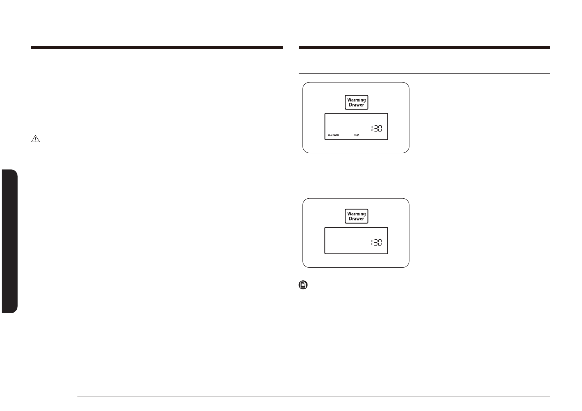
58 Français
Utilisation du tiroir chauffe-plat
Utilisation du tiroir chauffe-platUtilisation du tiroir chauffe-plat
À propos du tiroir chauffe-plat
(modèle NX58*565*** uniquement)
Le tiroir chauffe-plat vous permet de conserver les aliments cuits chauds. Les
aliments doivent être déjà chauds. N'utilisez pas le tiroir chauffe-plat pour chauffer
ou réchauffer des aliments froids.
Environ 25 minutes sont nécessaires pour préchauffer le tiroir chauffe-plat.
ATTENTION
N'utilisez pas de récipients en plastique, ni de lm plastique dans le tiroir chauffe-
plat. Le plastique fond s'il entre en contact direct avec le tiroir chauffe-plat. Il est
possible que le plastique fondu ne s'enlève plus. Ces dégâts ne sont pas couverts
par la garantie.
• Ne tapissez pas le tiroir chauffe-plat de papier d'aluminium. Le papier
d'aluminium est un excellent isolant thermique et aurait pour conséquence
d'emprisonner la chaleur. Son utilisation est susceptible de perturber le
fonctionnement du tiroir et d'endommager la nition intérieure.
• Ne placez pas de liquide ou d'eau dans le tiroir chauffe-plat.
• Tous les aliments placés dans le tiroir chauffe-plat doivent être recouverts
d'un couvercle ou de papier d'aluminium. Lorsque vous faites chauffer des
pâtisseries ou du pain, aménagez une ouverture dans le couvercle an de
permettre à l'humidité de s'échapper.
• Retirez les couverts de service, etc., avant de placer le récipient dans le tiroir
chauffe-plat.
• Conservez les aliments dans le récipient de cuisson ou transférez-les dans un
plat de service résistant à la chaleur.
• Le tiroir chauffe-plat ne peut pas être utilisé durant le cycle d'auto-nettoyage.
• Le tiroir chauffe-plat s'éteint automatiquement après 3 heures.
Activation ou désactivation du tiroir chauffe-plat
1. Appuyez sur la touche Warming Drawer
(Tiroir chauffe-plat) une fois pour
une température de chauffage faible,
deux fois pour une température de
chauffage intermédiaire, trois fois pour
une température de chauffage élevée,
ou quatre fois pour éteindre le tiroir
chauffe-plat.
Warming Drawer (Tiroir chauffe-
plat) et la lumière de la température
sélectionnée s’afchent à l’écran. Le
tiroir chauffe-plat commence à chauffer.
2. Pour éteindre le tiroir chauffe-plat,
appuyez sur la touche Warming Drawer
(Tiroir chauffe-plat) jusqu'à ce qu'il
s'éteigne.
Remarque
Appuyer sur la touche OFF/CLEAR (ARRÊT/EFFACER) ne permet pas d'éteindre le
tiroir chauffe-plat.
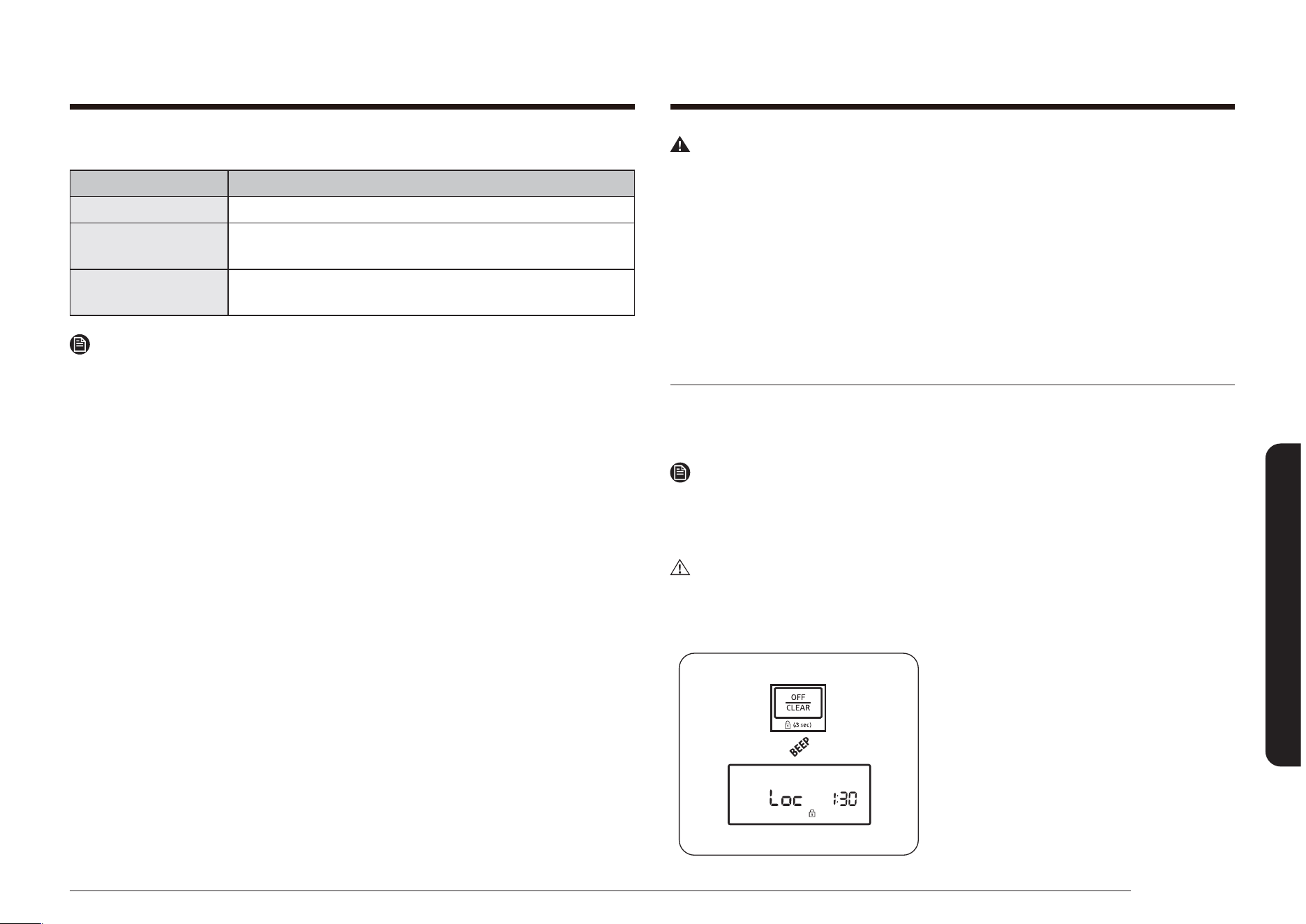
Français 59
Entretien de votre appareil
Réglages recommandés
RÉGLAGE DU TIROIR TYPE D'ALIMENTS*
FAIBLE Petits pains (mous), assiettes vides
MED
Rôtis (boeuf, porc, agneau), plats mijotés, légumes, oeufs,
pâtisseries, biscuits, petits pains (durs), sauces
ÉLEVÉE
Volaille, côtelettes de porc, hamburgers, pizza, bacon,
aliments fris
Remarque
* Vous pouvez placer simultanément différents types d’aliments dans le tiroir
chauffe-plat. Pour un résultat optimal, ne laissez pas les aliments pendant plus
d’une heure dans le tiroir chauffe-plat. Ne laissez pas d’aliments en petites
quantités ou sensibles à la chaleur, comme des œufs, pendant plus de 30 minutes.
Entretien de votre appareil
Avertissement
• Veillez toujours à ce que les commandes soient éteintes et que les surfaces
soient froides avant de retirer et/ou nettoyer une des pièces. Ceci élimine les
risques de brûlure.
• Si la cuisinière est, pour une quelconque raison, retirée du mur, assurez-vous
que le dispositif anti-basculement est convenablement rétabli une fois que
la cuisinière est remise en place. La non observation de cette consigne peut
provoquer un basculement de la cuisinière et, par conséquent, des blessures.
• Lors du nettoyage de l’appareil (extérieur ou intérieur), veillez à ne pas vous
blesser. Vous risquez de vous blesser avec les bords tranchants de l’apparei
Entretien et nettoyage du four
Les tableaux de commande du four et des brûleurs de surface peut être facilement
nettoyé à l'aide d'un chiffon humide et/ou de produit à vitre. Les surfaces très
sales peuvent être nettoyées avec de l'eau savonneuse chaude.
Remarque
N'utilisez jamais de laine de verre ou de nettoyant abrasif.
Protégez les surfaces des objets coupants.
Tous les objets cités peuvent endommager la surface.
ATTENTION
Portez des gants pendant le nettoyage.
Tableau de commande du four
1. Pour verrouiller les commandes et la
porte du four, maintenez la touche OFF/
CLEAR (ARRÊT/EFFACER) enfoncée
pendant 3 secondes. Ceci évite les
risques de mise en fonctionnement
accidentelles du four et le basculement
de l'appareil.
Un signal sonore retentit et l'écran
indique Loc (Verrouillé), l'heure, et le
symbole de verrouillage.
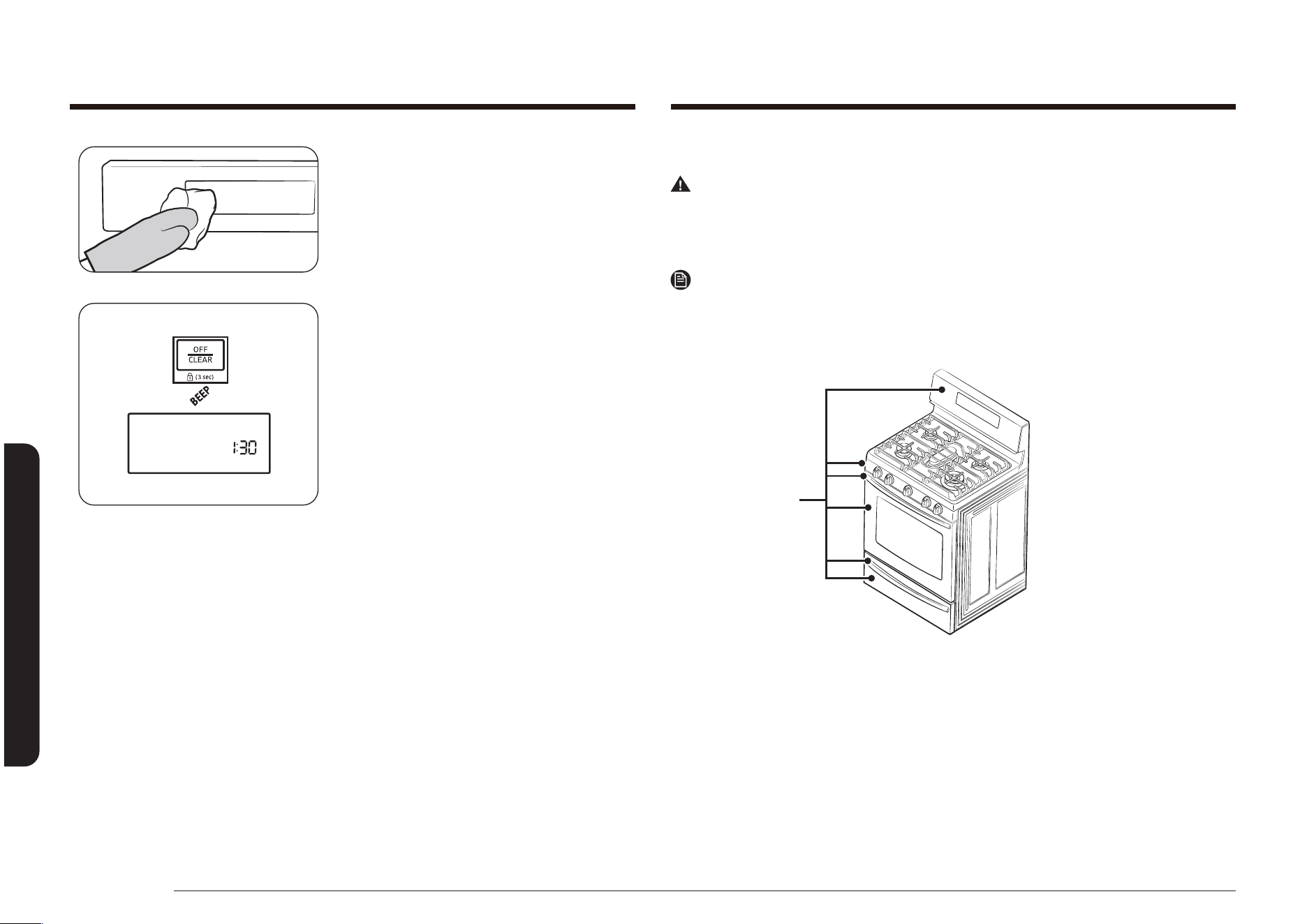
60 Français
Entretien de votre appareil
Entretien de votre appareil
2. Nettoyez les éclaboussures avec un
chiffon humide, du produit à vitres, ou
de l'eau savonneuse chaude.
3. Pour déverrouiller les commandes et la
porte, maintenez la touche OFF/CLEAR
(ARRÊT/EFFACER) enfoncée pendant
3 secondes.
Pour déverrouiller uniquement les
commandes, tenez la porte légèrement
entrouverte pendant que vous
maintenez la touche OFF/CLEAR
(ARRÊT/EFFACER) enfoncée pendant
3 secondes.
Un signal sonore retentit et l'indicateur
Loc ainsi que le symbole de verrouillage
disparaissent de l'écran. Fermez la porte
du four si vous la mainteniez ouverte.
Surfaces en acier inoxydable
Avertissement
N'utilisez pas d'éponge en laine de verre ou de nettoyants abrasifs sur les surfaces
en acier inoxydable. Les éponges et nettoyants abrasifs vont rayer la surface et
abîmer sa nition.
Remarque
An d'éviter toute décoloration et/ou tâche de graisse, nous vous conseillons de
nettoyer et d'enlever toute éclaboussure, tâche et graisse de la cuisinière après
chaque utilisation.
Surfaces
en acier
inoxydable
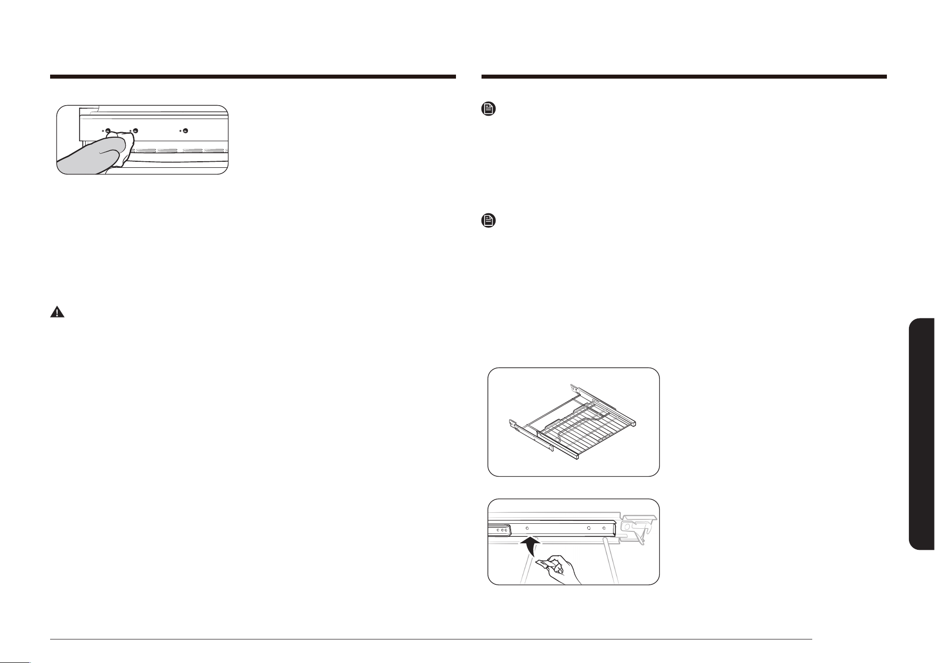
Français 61
Entretien de votre appareil
1. Essuyez toutes les éclaboussures avec
un chiffon doux humide.
2. Appliquez un nettoyant adapté à l'acier
inoxydable sur un chiffon propre
humide ou une serviette en papier.
Nettoyez précautionneusement une
petite surface en suivant les instructions
du nettoyant. Il est préférable de
nettoyer l'acier inoxydable dans le sens
de la largeur si possible.
3. Séchez et lustrez à l'aide d'un torchon
doux propre et sec.
4. Répétez les étapes 2 et 3 si nécessaire.
Avertissement
Ne vaporisez aucun type de nettoyant dans les trous du panneau de la coupelle.
Dans ces trous se trouvent des commutateurs d'allumage supportant le courant qui
éclaire la surface des brûleurs. Vaporiser un produit à l'intérieur peut endommager
la cuisinière.
Grilles de cuisson
• Si vous laissez les grilles dans le four durant un cycle d’auto-nettoyage, leur
couleur deviendra légèrement bleutée et l’aspect de leur surface se ternira.
Une fois le cycle d’auto-nettoyage terminé et le four refroidi, essuyez les
parties latérales des grilles à l’aide d’un papier sulfurisé ou d’un chiffon
légèrement huilé. Cela permettra une meilleure insertion des grilles dans leurs
glissières.
• Les grilles coulissantes peuvent être nettoyées à la main avec un nettoyant
abrasif ou de la laine de verre. Lors du nettoyage, veillez à ne pas laisser de
l’eau ou un nettoyant pénétrer dans les glissières sur les côtés de la grille.
Remarque
• Ne les nettoyez pas au lave-vaisselle.
• S'il devient difcile de retirer ou remplacer la grille, essuyez légèrement les
glissières de la grille du four avec de l'huile de cuisson. N'essuyez pas l'huile de
cuisson sur les glissières.
• Si la grille devient difcile à faire coulisser, il peut s’avérer nécessaire de la
lubrier avec du lubriant au graphite.
Remarque
• Pour commander du lubriant au graphite, appelez notre centre au
1-800-SAMSUNG (726-7864) ou rendez-vous sur notre page d’accueil
(www.samsung.com/us/support, www.samsung.com/ca/support (English) ou
www.samsung.com/ca_fr/support (French)) muni de la référence
DG81-01629A.
• Si vous souhaitez acheter directement, visitez le site de notre distributeurs de
pièces en ligne sur http://www.samsungparts.com/Default.aspx.
Pour lubrier les glissières
1. Retirez la grille du four. Reportez-vous
au retrait de la grille coulissante dans la
section COMMENT UTILISER LA GRILLE
COULISSANTE ?
2. Ouvrez complètement la grille sur une
table ou un plan de travail. Vous pouvez
placer un journal sous la grille pour vous
faciliter le nettoyage.
3. Si vous constatez la présence de débris
sur les glissières, essuyez-les à l’aide
d’une serviette en papier. (Le lubriant
au graphite retiré lors de l’essuyage
doit être remplacé – Reportez-vous aux
étapes 4 à 7.)
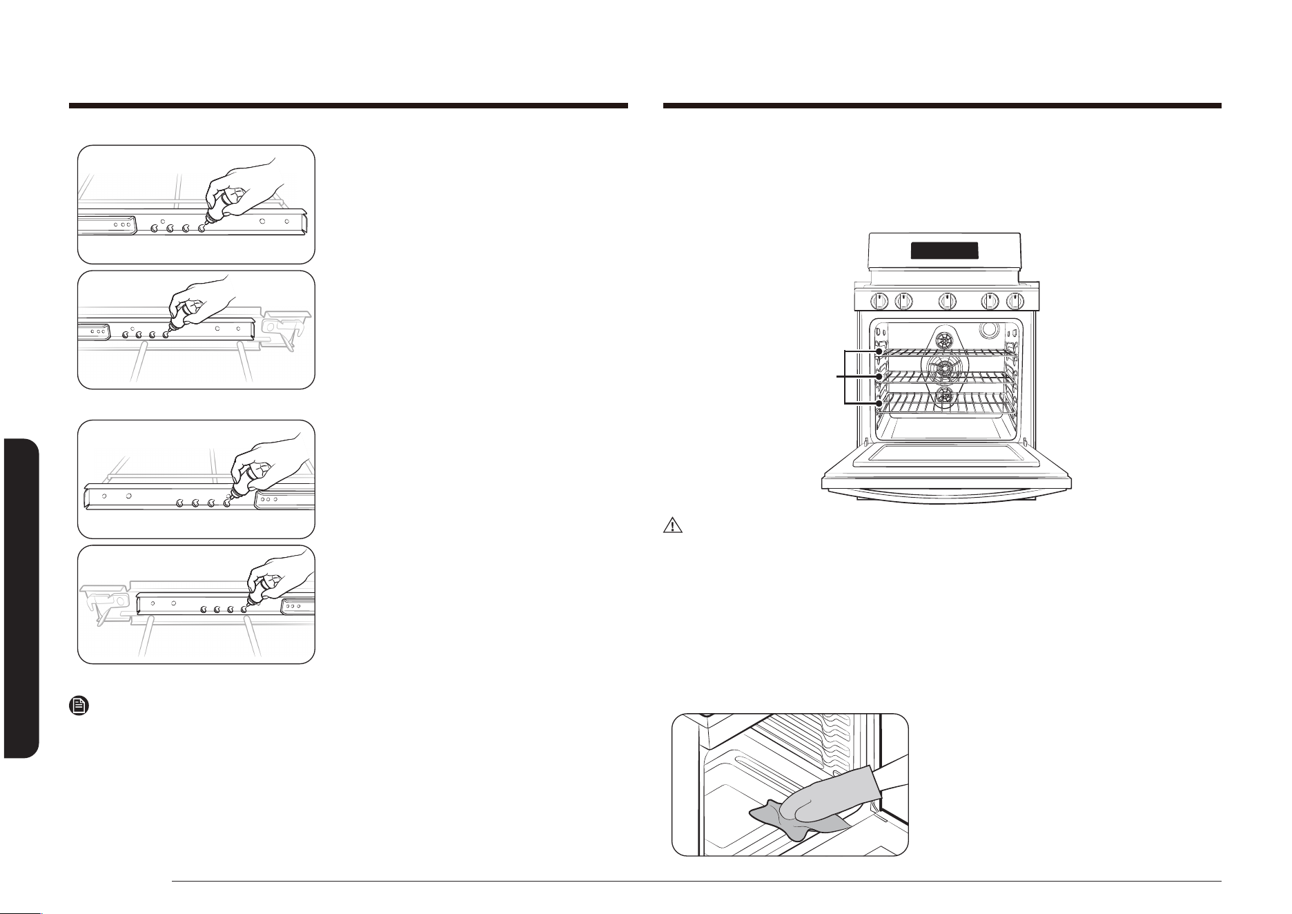
62 Français
Entretien de votre appareil
Entretien de votre appareil
4. Secouez le lubriant au graphite avant
de l’ouvrir. En commençant par le
mécanisme de glissière côté gauche
(avant et arrière) de la grille, posez
quatre (4) petites gouttes de lubriant
sur les deux (2) pistes inférieures de la
glissière à proximité des supports.
5. Répétez l’opération sur le mécanisme de
glissière côté droit (avant et arrière) de
la grille.
6. Ouvrez et fermez la grille plusieurs fois
pour répartir le lubriant.
7. Replacez le bouchon sur le lubriant
et secouez-le à nouveau. Retournez la
grille et répétez les étapes 3, 4, 5 et 6.
8. Fermez la grille, tournez-la côté
droit dessus et placez-la dans le four.
Reportez-vous à l’installation de la grille
coulissante dans la section COMMENT
UTILISER LA GRILLE COULISSANTE ?
Remarque
Ne pulvérisez pas la matière grasse végétale en bombe ni n’utilisez pas d’autres
pulvérisateurs de lubriant sur la grille coulissante.
Grilles de cuisson
Pour que les grilles restent brillantes et comme neuves, retirez-les du four et
nettoyez-les à la main dans de l’eau chaude savonneuse, avec une éponge en
plastique ou une éponge à récurer imbibée de savon.
Grilles du
four
ATTENTION
Ne laissez pas les grilles dans le four pendant un cycle de nettoyage automatique.
La chaleur extrême du cycle de nettoyage automatique peut décolorer de façon
irréversible les grilles et les rendre difciles à faire glisser.
S’il devient difcile de faire glisser les grilles, frottez les rails latéraux avec du
papier sulfurisé ou un chiffon contenant une petite quantité d’huile de cuisine. Cela
permettra une meilleure insertion des grilles dans les glissières.
Four
Portez des gants pendant le nettoyage.
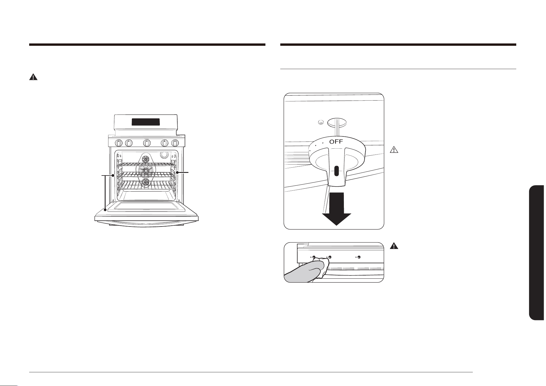
Français 63
Entretien de votre appareil
Entretien et nettoyage de la plaque de cuisson
Commandes des brûleurs de surface
1. Assurez-vous que les boutons des
brûleurs de surface soient sur la position
OFF (ARRÊT).
2. Retirez les boutons de commande des
tiges de la vanne de commande des
brûleurs de surface.
ATTENTION
Ne lavez pas les boutons de commande
dans un lave-vaisselle. Ils ne sont pas
adaptés au lave-vaisselle.
3. Nettoyez les boutons de commande
à l'eau chaude savonneuse. Rincez et
séchez intégralement toutes les surfaces
(dont l'arrière et le trou de la tige).
Avertissement
N'utilisez pas de spray nettoyant sur le
tableau de commande des brûleurs de
surface. Si des éclaboussures entrent
dans les trous de la vanne, elles peuvent
entraîner des dégâts matériels, des
blessures individuelles ou des blessures
mortelles.
4. Nettoyez les surfaces en acier
inoxydable avec un chiffon doux et
humide imprégné d'un produit adapté.
Voir page 60.
Porte du four
Avertissement
Ne laissez pas d’humidité s’insérer dans la porte ou le joint de celle-ci pendant le
nettoyage. L’humidité entrant dans l’assemblage de la porte ou un joint de porte
humide peut endommager ce joint.
Ne déplacez ni
nettoyez pas le
joint.
Les zones grises
sont à nettoyer à
la main.
La porte du four contient différents types de surfaces qui nécessitent des
techniques de nettoyage différentes. Le joint sur la surface intérieure de la porte
du four ne doit jamais être nettoyé ou enlevé pour nettoyer d’autres surfaces. Le
joint est constitué d’un matériau tissé essentiel à son bon fonctionnement.
La surface intérieure de la porte autour du joint doit être nettoyée à la main, avec
de l’eau chaude savonneuse ou une éponge à récurrer en plastique savonneuse.
Rincez et séchez à l’aide d’un torchon doux et propre. N’humidiez pas le joint et
ne laissez pas d’humidité s’insérer dans l’assemblage de la porte.
Le joint de la surface intérieure de la porte et la vitre de la porte sont nettoyés
automatiquement pendant le cycle d’auto-nettoyage.
La surface extérieure de la porte est en acier inoxydable et doit être nettoyée en
respectant les consignes que vous trouverez à la page 60.
La surface de la vitre extérieure peut être nettoyée avec un produit à vitres ou de
l’eau chaude savonneuse suivie d’un rinçage abondant. Ne laissez pas l’humidité
pénétrer dans l’assemblage de la porte.

64 Français
Entretien de votre appareil
Entretien de votre appareil
2. Soulevez et retirez les grilles du brûleur
de la plaque de cuisson. Souvenez-vous
des tailles et emplacements des brûleurs
sur tous les brûleurs de surface.
3. Soulevez les châpeaux des têtes des
brûleurs.
4. Retirez les têtes des brûleurs des
coupelles de la vanne et des électrodes
de démarrage.
5. Nettoyez toutes les parties amovibles
du brûleur à l’eau chaude savonneuse.
N’utilisez pas de tampon à récurrer
métallique ou de nettoyants abrasifs sur
une des parties du brûleur.
6. Rincez abondamment et séchez
intégralement toutes les parties avant
de les rassembler.
Remarque
• Une fois le nettoyage terminé, vériez
que les ouvertures des orices des
brûleurs ne sont pas obstruées.
• Essuyez l’excès d’eau et laissez les têtes
de brûleurs et les chapeaux sécher
complètement. L’eau s’écoulera plus
facilement si le brûleur central est placé
à l’envers.
• Ne lavez aucun composant des brûleurs
au lave-vaisselle.
5. Remettez les boutons de commande sur
la position OFF (ARRÊT), en les poussant
sur les tiges de la vanne de commande.
Grilles des brûleurs de surface et assemblages
1. Éteignez toutes les commandes et
assurez-vous que toutes les pièces ont
refroidi.
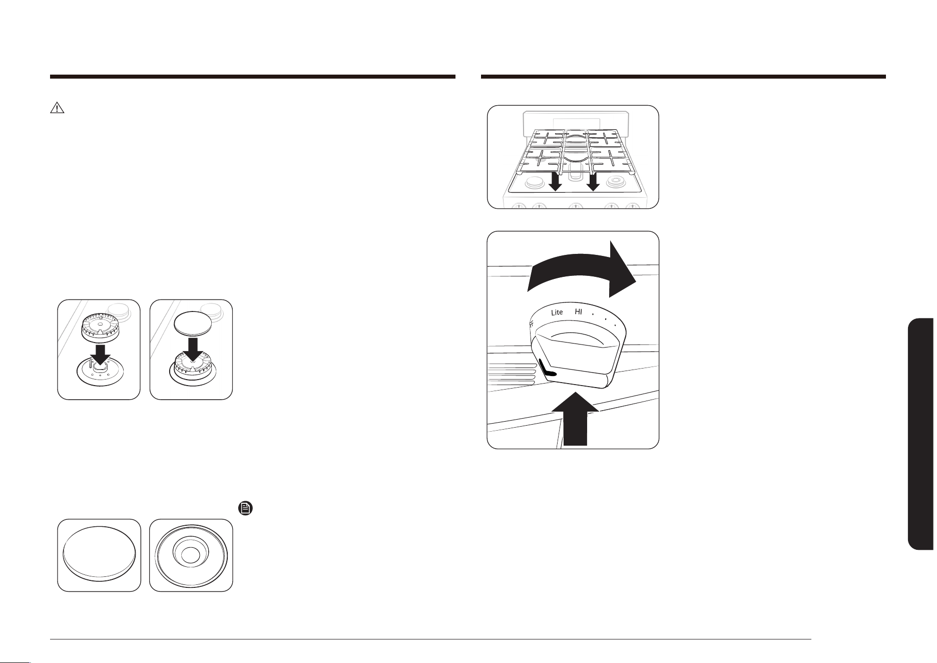
Français 65
Entretien de votre appareil
9. Replacez les grilles des brûleurs sur la
plaque de cuisson de la cuisinière.
10. Enfoncez et tournez chaque bouton
de commande des brûleurs de surface
sur la position LITE (ALLUMER), puis
remettez-les sur le réglage du brûleur
pour s’assurer qu’ils fonctionnent
correctement.
ATTENTION
• Les électrodes de démarrage ne sont pas amovibles. Ne tentez pas de les
retirer en forçant.
• An d'éviter tout écaillage, ne cognez pas les grilles ou les chapeaux les un(e)
s contre les autres ou contre des surfaces dures, par exemple des récipients en
fonte.
• La tête des brûleurs peut être obstruée par de la nourriture ou de la poussière.
Nettoyez la tête si elle semble obstruée. Si vous nettoyez la tête à l’eau, ne la
reassemblez qu’une fois qu’elle est parfaitement sèche Une tête mouillée peut
empêcher les brûleurs de s’allumer.
• Pour éviter de faire tomber les grilles, veillez à retirer d'abord les deux grilles
latérales.
• N’essayez pas d’enlever le chapeau du brûleur oval central de la tête.
7. Placez toutes les têtes des brûleurs
au-dessus des vannes de coupelle, à
leur emplacement initial. Le trou sur le
côté des têtes de brûleur se place face
aux électrodes. Les têtes des brûleurs
sont positionnées correctement si elles
sont à plat sur le dessus des vannes de
coupelle.
8. Placez tous les châpeaux sur les têtes
des brûleurs.
Ceux-ci doivent également être à plat
pour assurer une utilisation appropriée
et sans danger.
Brûleur de mijotage précis (ArD)
Remarque
Le chapeau du brûleur de mijotage précis
(ArD) et l’intérieur du double brûleur
(AvD) peuvent être utilisés de façon
interchangeable.
Surface plate Ligne concave
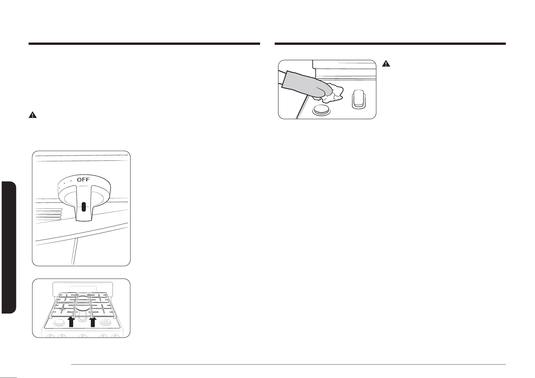
66 Français
Entretien de votre appareil
Entretien de votre appareil
Avertissement
N’enlevez pas ou ne soulevez pas la plaque
de cuisson pendant le nettoyage. Sinon,
vous risquez d’endommager les conduites
de gaz menant jusqu’aux coupelles des
brûleurs, entraînant ainsi un fonctionnement
défectueux et/ou dangereux.
3. Nettoyez la surface de la plaque de
cuisson avec un chiffon doux humide
et de l’eau savonneuse tiède. Si des
éclaboussures se nichent sous un
brûleur de surface, retirez le châpeau et
la tête an d’accéder à l’éclaboussure et
la nettoyer.
4. Rincez à l’eau claire, séchez et cirez avec
un chiffon doux et sec.
5. Rassemblez les composants du brûleur
(si retiré) et remettez les grilles.
Surface de la plaque de cuisson
La surface de la plaque de cuisson est en émail vitrié. Pour éviter que cette
surface ne devienne sombre, essuyez et nettoyez toutes les éclaboussures lorsqu’il
y en a. Des aliments contenant beaucoup d’acidité (tomates, choucroute, jus de
fruits, etc.) ou des aliments à forte teneur en sucre peuvent causer des taches
sombres.
Avertissement
N’utilisez pas d’éponge en laine de verre ou de nettoyants abrasifs sur les surfaces
en émail vitrié. Les éponges et nettoyants abrasifs peuvent rayer et abîmer la
surface.
1. Assurez-vous que tous les brûleurs sont
éteints.
2. Lorsque les surfaces ont refroidi,
enlevez les grilles des brûleurs.
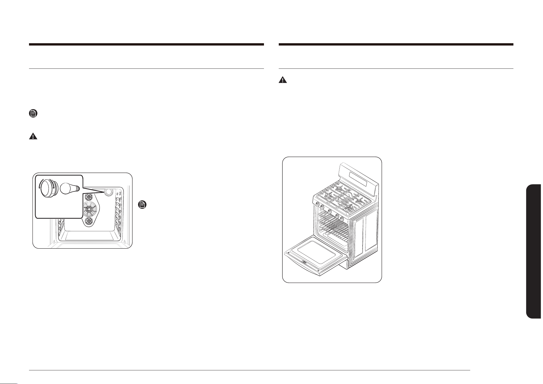
Français 67
Entretien de votre appareil
Retrait et remise en place de la porte du four
Avertissement
• La porte du four est très lourde. Ne la soulevez pas par la poignée et faites
attention à ne pas échapper la porte pendant le retrait. Une manipulation
inappropriée peut engendrer des blessures corporelles.
• Débranchez l’alimentation électrique de la cuisinière avant d’enlever la porte
du four. Ce geste permet d’éviter un allumage involontaire du four alors que la
porte est retirée.
Pour retirer la porte :
1. Ouvrez complètement la porte du four.
Remplacement de l’ampoule du four
L’éclairage du four nécessite une ampoule standard de 40 watts. L’éclairage
s’active à l’ouverture de la porte. La lumière peut également être allumée ou
éteinte lorsque la porte du four est fermée en appuyant sur la touche OVEN LIGHT
(LUMIÈRE DU FOUR) sur le tableau de commande.
Remarque
L’éclairage est désactivé durant le cycle d’auto-nettoyage.
Avertissement
Débranchez l’alimentation électrique de la cuisinière avant de remplacer
l’ampoule du four. Ce geste permet d’éviter des blessures individuelles dues à une
électrocution.
Protection de
l'ampoule et
ampoule du four
1. Assurez-vous que le four et l’ampoule
sont froids.
2. Ouvrez la porte du four.
Remarque
Si les grilles du four gênent, elles peuvent
être changées de place ou retirées avant le
changement de l’ampoule du four.
3. Tournez le cache en verre de l’ampoule
(situé dans le coin supérieur droit de la
paroi du fond) dans le sens anti-horaire.
4. Tournez l’ampoule dans le sens inverse
des aiguilles d’une montre pour la
retirer de sa douille.
5. Installez une ampoule neuve de 40 W.
Tournez l’ampoule dans le sens horaire
jusqu’à ce qu’elle soit correctement
insérée dans son socle.
6. Remettez le cache en verre de l’ampoule
en tournant dans le sens horaire jusqu’à
ce qu’il soit correctement positionné.
7. Fermez la porte du four et rebranchez
l’alimentation électrique de la cuisinière.
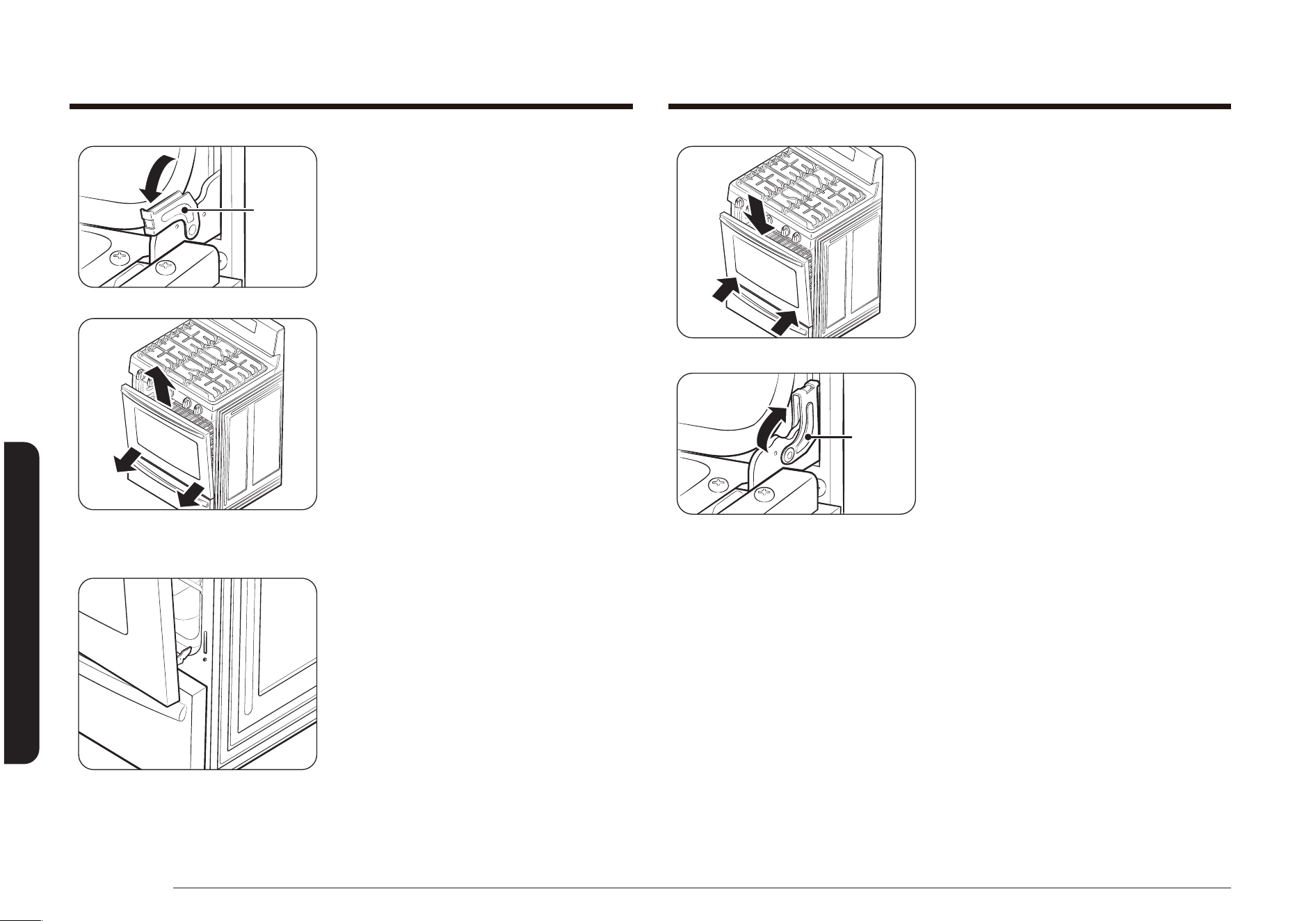
68 Français
Entretien de votre appareil
Entretien de votre appareil
2. Attrapez fermement les deux côtés de
la porte.
3. Tout en portant la porte du four, insérez
les deux bras de la charnière dans leurs
logements situés sur les côtés inférieurs
du cadre de la porte. Lorsque la porte
est tenue à environ 5 degrés, les bras
de la charnière glissent vers le bas, à
l’intérieur.
Verrou
de la
charnière
4. Ouvrez complètement la porte du four.
Si la porte ne s’ouvre pas entièrement,
les bras de la charnière ne sont pas
correctement insérés dans leurs
logements.
5. Verrouillez les deux verrous de la
charnière. Remontez chaque verrou
contre le cadre avant de la cavité du
four.
6. Refermez la porte.
7. Rebranchez l’alimentation électrique de
la cuisinière.
Verrou
de la
charnière
2. Déverrouillez les deux verrous de la
charnière. Rabattez chaque verrou de
charnière vers le cadre de la porte pour
le déverrouiller an d’obtenir un résultat
comme indiqué sur l’illustration à droite.
3. Fermez la porte en position de retrait,
jusqu’à environ 5 degrés de la verticale.
4. Attrapez fermement les deux côtés de la
porte du four et soulevez-la vers vous
jusqu’à ce que les bras de la charnière
situés en bas soient délogés.
5. Posez délicatement la porte dans un lieu
sûre.
Pour remonter la porte :
1. Assurez-vous que les bras de la
charnière sont déverrouillés et en
position de retrait.

Français 69
Entretien de votre appareil
Comment remettre le tiroir chauffe-plat en place ?
Rail droit du
plateau tournant
1. Placez les extrémités des rails du
plateau tournant à extension complète
dans les rails latéraux de l’ouverture du
tiroir.
2. Poussez le tiroir an de pouvoir
le fermer et remettez les clips de
verrouillage.
Enlever et remettre le tiroir chauffe-plat
(modèle NX58*565***)
Pour enlever et nettoyer le tiroir chauffe-plat
1. Tirez le tiroir vers vous jusqu’à ce qu’il
arrive en butée.
Clip de
verrouillage
droit du tiroir
Clip de
verrouillage
gauche du tiroir
2. Repérez les clips de verrouillage situés
près de l’extrémité arrière des rails du
plateau tournant à extension complète.
Avec vos deux mains, baissez le clip
gauche et levez le droit pour les libérer.
Retirez le tiroir entièrement.
3. Nettoyez le tiroir à l’eau chaude
savonneuse. Rincez et séchez
minutieusement.

70 Français
Entretien de votre appareil
Entretien de votre appareil
Comment remettre le tiroir de rangement en place ?
1. Placez la partie supérieure des deux
côtés du tiroir sur les deux guidages en
nylon et enfoncez sufsamment pour
supporter le tiroir.
2. Remettez le contenu et poussez le tiroir
tout en soulevant légèrement l’avant
pour le fermer.
Enlever et remettre le tiroir de rangement
(modèle NX58*560***, NX58*751***)
Comment retirer le tiroir de rangement ?
1. Retirez le tiroir et son contenu.
2. Tout en portant le tiroir, tirez-le jusqu’à
ce que les côtés supérieurs sortent des
deux rainures en nylon du tiroir. Ensuite,
soulevez le tiroir pour l’enlever.
3. Nettoyez le tiroir à l’eau chaude
savonneuse. Rincez et séchez
minutieusement.
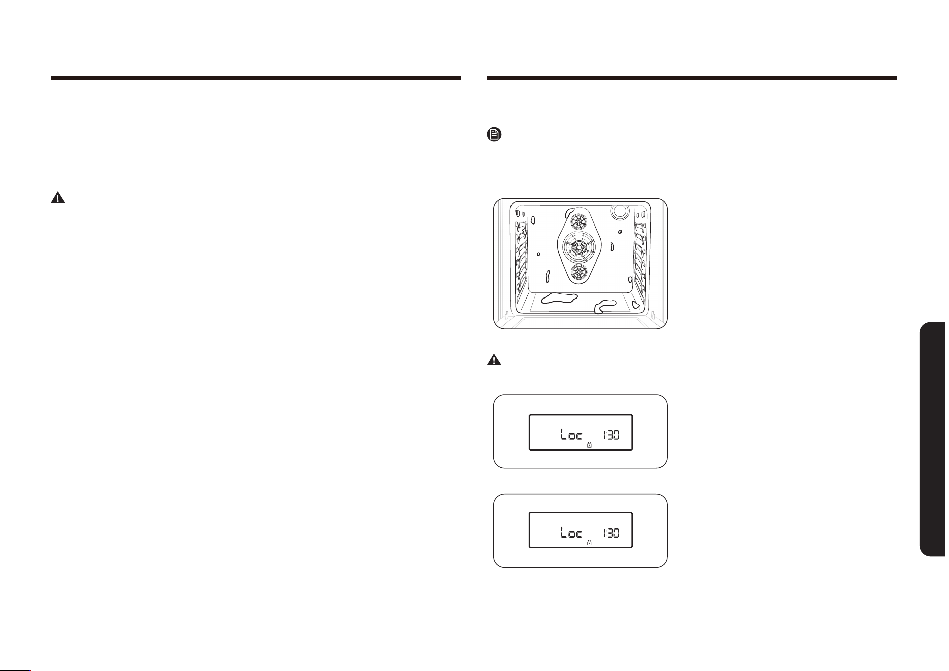
Français 71
Entretien de votre appareil
Avant le cycle d'auto-nettoyage
Remarque
Enlevez les grilles. Laisser les grilles dans le four pendant le cycle d'auto-
nettoyage peut les décolorer et les rendre difciles à insérer dans les différentes
positions.
• Veillez à ce que le dispositif de
verrouillage des commandes soit éteint
et que le four soit froid. Ces conditions
permettent d'éviter le démarrage d'un
cycle d'auto-nettoyage.
• Sur le modèle NX58*565***, veillez à
éteindre le tiroir chauffe-plat. L'auto-
nettoyage ne commence pas si le tiroir
est allumé.
Avertissement
N'utilisez PAS les brûleurs de surface pendant un cycle d'auto-nettoyage du four.
• Un symbole Loc (Verrouillage)
clignotant indique que la porte est en
processus de verrouillage.
• Lorsque le symbole Loc (Verrouillage)
est allumé, la porte du four est
verrouillée.
Auto-nettoyage du four
Le cycle d’auto-nettoyage produit une température très élevée (bien supérieure
aux températures de cuisson) an de brûler complètement les résidus de graisse
ou les réduire en poudre ; il vous suft ensuite de les retirer à l’aide d’un torchon
humide.
Avertissement
Le non-respect des ces consignes peut entraîner des dommages sur le four, un
incendie, et/ou des blessures individuelles.
• Ne laissez jamais de jeunes enfants sans surveillance à proximité de la
cuisinière durant le cycle d’auto-nettoyage. Les surfaces extérieures de la
cuisinière peuvent devenir très chaudes.
• Certains oiseaux sont très sensibles aux fumées émises par le cycle d’auto-
nettoyage du four. Déplacez les oiseaux dans une pièce bien aérée, loin de la
cuisinière.
• Ne recouvrez pas le four, les grilles ou le dessous du four avec du papier
aluminium. La chaleur serait ainsi mal distribuée, les résultats de cuisson
altérés et l’intérieur du four endommagé de façon irréversible. Le papier
aluminium peut fondre à l’intérieur du four.
• Ne forcez jamais l’ouverture de la porte du four. Vous risqueriez
d’endommager le système de verrouillage automatique de la porte. La porte
se verrouille automatiquement lorsque le cycle d’auto-nettoyage commence et
reste verrouillée jusqu’à ce que le cycle soit annulé et que la température du
four descende en dessous de 177 °C (350 °F).
• Soyez prudent en ouvrant la porte du four après un cycle d’auto-nettoyage.
Le four reste TRÈS CHAUD et de l’air chaud ainsi que de la vapeur peuvent
s’échapper à l’ouverture de la porte.
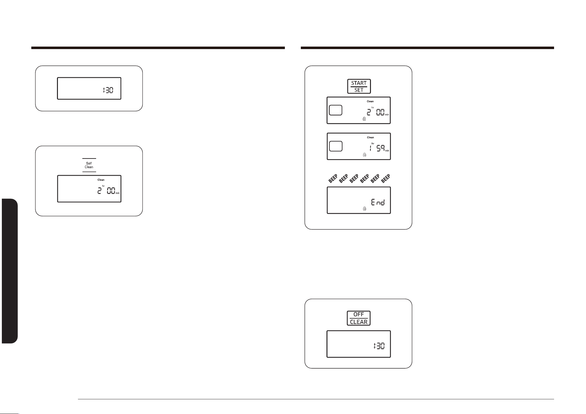
72 Français
Entretien de votre appareil
Entretien de votre appareil
3. Appuyez sur la touche START/SET
(DÉPART/RÉGLAGE) pour commencer le
cycle.
L'indicateur Clean (Effacer), ainsi
que la durée de cycle sélectionnée
apparaissent à l'écran, et le symbole
Lock (Verrouillage) clignote jusqu'à ce
que la porte soit fermée. Puis le symbole
Lock (Verrouillage) reste jusqu'à la n
du cycle et la baisse de température du
four en dessous de 177°C (350 °F).
La température du four augmente et
stagne à la température préréglée pour
l'auto-nettoyage pendant toute la durée
du cycle de nettoyage. L'écran afche le
décompte en heures et minutes du cycle
de nettoyage.
Une fois le temps écoulé, le four s'arrête
et un signal sonore retentit 6 fois. End
(Fin) s'afche à l'écran et le symbole
Lock (Verrouillage) clignote. Lorsque
la température du four est inférieure à
177°C (350 °F), la porte se déverrouille
et le symbole Lock (Verrouillage)
disparaît.
4. Appuyez sur la touche OFF/CLEAR
(ARRÊT/EFFACER).
L'écran revient à l'afchage de l'heure
actuelle.
• Lorsque Loc apparaît à l'écran, il indique
que le dispositif de verrouillage des
commandes est actif. Maintenez la
touche OFF/CLEAR (ARRÊT/EFFACER)
pendant 3 secondes pour déverrouiller
les commandes du four.
Comment régler le four pour l'auto-nettoyage ?
1. Assurez-vous que la porte est
correctement fermée.
2. Appuyez sur la touche Self Clean (Auto-
nettoyage) sur le tableau de commande
du four.
Appuyez sur la touche une fois pour un
cycle de nettoyage de 2 heures, deux
fois pour un cycle de nettoyage de 3
heures, ou trois fois pour un cycle de
nettoyage de 4 heures.
Appuyer sur la touche une quatrième
fois resélectionne le temps par défaut
(2 heures).
L'écran afche l'indicateur Clean
(Effacer), et l'indicateur Start
(Démarrage) clignote sous la durée de
cycle sélectionnée.
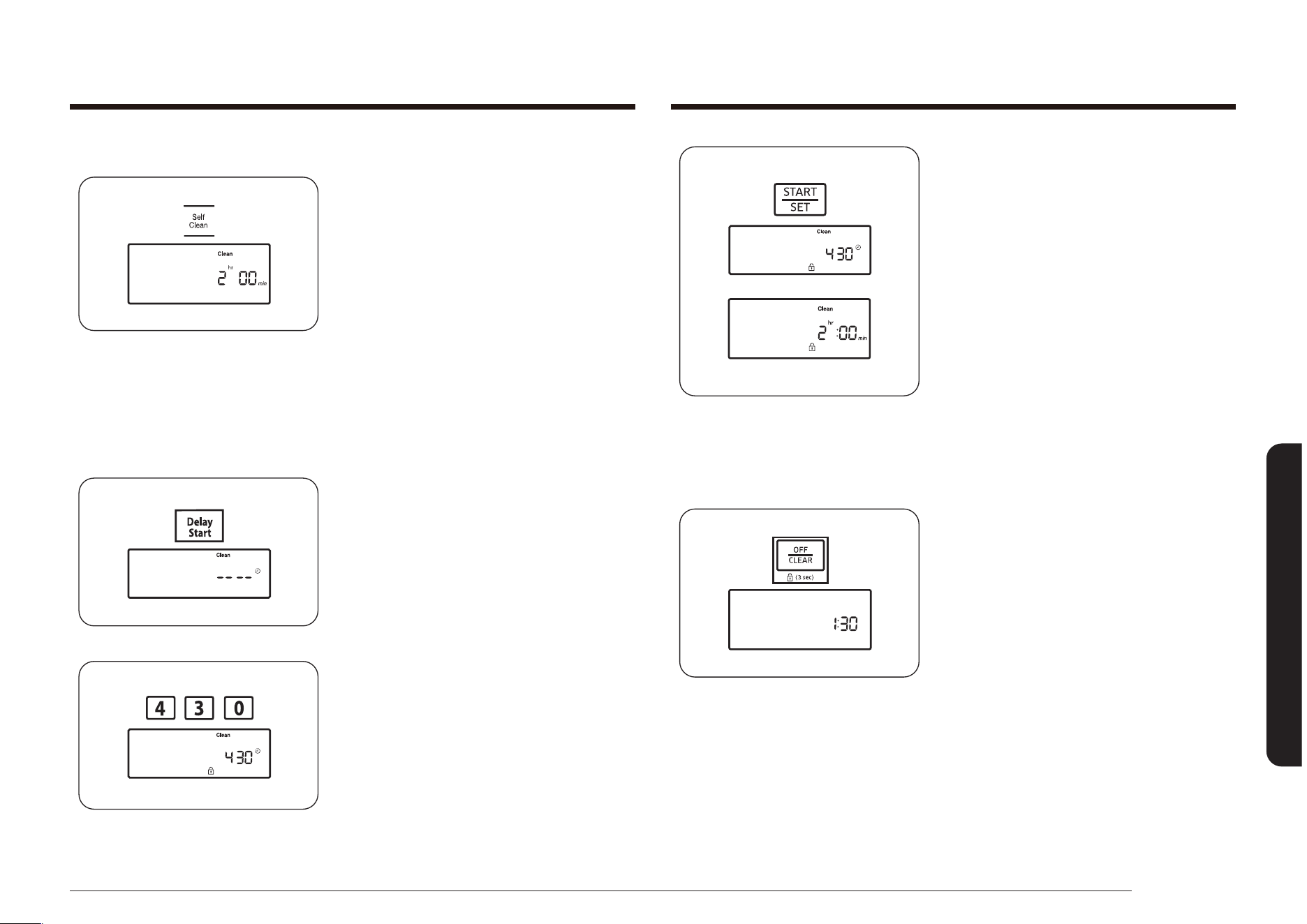
Français 73
Entretien de votre appareil
5. Appuyez sur la touche START/SET
(DÉPART/RÉGLAGE).
L'écran afche l'heure du Delay
Start (Départ Différé) et le symbole
Lock (Verrouillage). Le verrouillage
de la porte du four s'enclenche
automatiquement.
À l'heure de départ programmée, le four
s'allume automatiquement et commence
le cycle de nettoyage programmé.
Comment annuler l'auto-nettoyage ?
Il peut s'avérer nécessaire d'arrêter ou d'interrompre le cycle d'auto-nettoyage en
raison d'une fumée excessive ou d'un incendie dans le four.
• Appuyez sur la touche OFF/CLEAR
(ARRÊT/EFFACER).
Le four s'éteint. Le symbole Lock (Verrouillage) clignote sous l'heure actuelle.
Lorsque la température du four est inférieure à 177 °C (350 °F), la porte se
déverrouille et le symbole Lock (Verrouillage) disparaît.
Comment différer le cycle d’auto-nettoyage ?
1. Assurez-vous que la porte est
correctement fermée.
2. Appuyez sur la touche Self Clean (Auto-
nettoyage) sur le tableau de commande
du four.
Appuyez sur la touche une fois pour un
cycle de nettoyage de 2 heures, deux
fois pour un cycle de nettoyage de 3
heures, ou trois fois pour un cycle de
nettoyage de 4 heures.
L'écran afche l'indicateur Clean
(Effacer), et l'indicateur Start
(Démarrage) clignote sous la durée de
cycle sélectionnée.
3. Appuyez sur la touche DELAY START
(DÉPART DIFFÉRÉ).
L'écran afche Delay (Retard) et -- --.
4. Appuyez sur les chiffres de la durée
pendant laquelle vous souhaitez que le
four fonctionne (ex : 4, 3, 0).
L'indicateur Start (Démarrage)
clignote sous l'heure du départ différé
sélectionnée et l'indicateur Delay
(Retard).
74 Français
Dépannage
Dépannage
Après l'auto-nettoyage
ATTENTION
Soyez prudent en ouvrant la porte du four après un cycle d'auto-nettoyage.
Lorsque la porte se déverrouille, le four est encore très chaud. Des échappements
d'air chaud et/ou de vapeur pourraient vous brûler.
• La température interne du four doit être inférieure à 177 °C (350 °F) pour que
la porte se déverrouille automatiquement. Le verrouillage automatique doit
être désactivé avant de programmer un autre mode de cuisson.
• Une fois le four froid, essuyez les surfaces du four avec un chiffon humide
pour enlever toutes les cendres résiduelles.
• Les tâches tenaces peuvent être nettoyées avec un tampon à récurrer imbibé
de savon. Les dépôts de tartre peuvent être retirés à l'aide d'un chiffon imbibé
de vinaigre. Rincez abondamment après le nettoyage.
• Si le four n'est toujours pas propre après un cycle, répétez le cycle. Si le four
est encore chaud, l'indicateur HOT (CHAUD) apparaît à l'écran jusqu'à ce que le
four soit assez froid pour commencer un nouveau cycle.
• Pour que l'auto-nettoyage puisse fonctionner, vous devez attendre 2 heures
après l'exécution du cycle d'auto-nettoyage.
Dépannage
Dépannage
Samsung veille à ce que vous ne rencontriez pas de problèmes lors de l'utilisation
de votre nouvelle cuisinière à gaz. En cas de problème, recherchez en premier
lieu une solution dans le tableau ci-dessous. Si, après avoir essayé la solution
proposée, vous ne parvenez pas à résoudre le problème, contactez Samsung au
1-800-SAMSUNG (726-7864).
PROBLÈME CAUSE POSSIBLE SOLUTION
Vous sentez
une odeur de
gaz.
Il y a une fuite de gaz.
Le bouton du brûleur de
surface n'est pas positionné
sur la position ‘off’, mais le
brûleur ne s'est pas enammé.
Evacuez la pièce, l'immeuble
ou le quartier de tous les
occupants.
Appelez immédiatement
votre fournisseur de gaz
à partir du téléphone d'un
voisin. N'appelez pas de votre
ligne xe. Elle est électrique
et pourrait provoquer
une étincelle qui risque
d'enammer le gaz. Suivez
les instructions de votre
fournisseur de gaz.
Si vous n'arrivez pas à joindre
votre fournisseur de gaz,
appelez les pompiers.
Français 75
Dépannage
PROBLÈME CAUSE POSSIBLE SOLUTION
La cuisinière
n'est pas à
niveau.
La cuisinière n'a pas été
installée correctement.
Le(s) pied(s) de mise à niveau
est/sont endommagé(s) ou
inégal.
Assurez-vous que le sol est
plan, solide et stable. Si le
sol est affaissé ou incliné,
contactez un charpentier.
Vériez et mettez la cuisinière
à niveau. (Reportez-vous aux
consignes d'installation.)
Les placards de la cuisine ne
sont pas correctement alignés
et donnent l'impression que la
cuisinière n'est pas à niveau.
Assurez-vous que les
éléments de cuisine sont
droits et que l'espace est
sufsant pour l'installation.
La commande
du four émet
un signal
sonore et
afche un code
d'erreur.
Il s'agit d'un code d'erreur de
fonction. Reportez-vous au
tableau Dépannage et codes
d'erreur à la page 80.
Appuyez sur la touche OFF/
CLEAR (ARRÊT/EFFACER)
et redémarrez le four. Si le
problème persiste, coupez
l'alimentation de la cuisinière
pendant 30 secondes puis
rétablissez-la. Si le problème
n'est pas résolu, contactez le
service technique.
Tous les
brûleurs ne
s'allument pas.
Le cordon d'alimentation n'est
pas correctement branché sur
la prise murale.
Assurez-vous que la cuisinière
est branchée sur une
prise en état de marche et
correctement mise à la terre.
Un fusible de votre habitation
est peut-être grillé ou le
disjoncteur a peut-être lâché.
Remplacez le fusible concerné
ou remettez le disjoncteur en
marche.
Le tuyau d'arrivée de gaz
n'est pas correctement
branché ou ouvert.
Reportez-vous aux consignes
d'installation fournies avec
votre cuisinière.
PROBLÈME CAUSE POSSIBLE SOLUTION
Les brûleurs ne
s'allument pas.
Le bouton de commande n'est
pas correctement réglé.
Enfoncez et tournez le bouton
de commande sur la position
LITE (ALLUMER).
Les chapeaux des brûleurs
ne sont pas correctement
positionnés.
La base des brûleurs n'est pas
correctement alignée.
Nettoyez les électrodes.
Placez le chapeau de brûleur
sur la tête de brûleur an
que la base de brûleur soit
alignée.
Le brûleur
émet un clic
pendant le
fonctionnement.
Le bouton de commande a
été laissé sur la position LITE
(ALLUMER).
Lorsque le brûleur s'allume,
tournez le bouton de
commande sur le réglage
souhaité.
Si le brûleur continue à
émettre un clic, contactez un
technicien de maintenance.
Les brûleurs
ne brûlent
pas de façon
homogène.
Les composants et les caches
des brûleurs de surface
n’ont pas été correctement
assemblés et mis à niveau.
Voir page 64.
Les brûleurs de surface sont
sales.
Nettoyez les composants des
brûleurs de surface. (Voir
pages 64 et 65.)
Les ammes
du brûleur de
surface sont
très larges ou
jaunes.
Un orice erroné a été
assemblé.
Contactez votre installateur.
Vériez la taille de l’orice
du brûleur et contactez votre
installateur si vous n’avez pas
le bon orice. Contrôlez la
conversion au gaz GPL.
76 Français
Dépannage
Dépannage
PROBLÈME CAUSE POSSIBLE SOLUTION
Les brûleurs
de surface
s'allument,
mais les
brûleurs
du four ne
s'allument pas.
Le verrouillage des
commandes du four est
activé.
L’icône de verrouillage
s’afche. Maintenez la touche
START/SET (DÉMARRAGE/
RÉGLAGE) enfoncée pendant
3 secondes. Un signal sonore
retentit et le symbole de
verrouillage disparaît de
l'écran.
Le commutateur pour
désactiver le régulateur de
pression de gaz se trouve sur
la position off (désactivé).
Contactez un technicien de
maintenance qualié.
L'afchage
s'atténue.
L'interrupteur différentiel (GFI
ou GFCI) a lâché et doit être
réinitialisé.
Votre commande numérique
est endommagée.
Remplacez le fusible concerné
ou remettez le disjoncteur en
marche.
Les ammes
du brûleur sont
très larges ou
jaunes.
Les volets d'air du brûleur du
four doivent être réglés.
Contactez un technicien de
maintenance qualié.
Le tuyau d'arrivée de gaz
n'est pas correctement
branché ou ouvert.
Reportez-vous aux consignes
d'installation fournies avec
votre cuisinière.
PROBLÈME CAUSE POSSIBLE SOLUTION
Les aliments
ne cuisent
pas ou ne
sont pas rôtis
correctement
au four.
Un mode de cuisson erroné a
été sélectionné.
Voir page 30-31, 41,
47.
Les grilles du four n'ont pas
été positionnées correctement
pour les aliments à cuire.
Voir page 35.
Un récipient inadapté ou de
taille inappropriée est utilisé.
Voir page 27.
Le thermostat du four doit
être réglé.
Voir page 39.
Il y a du papier aluminium
sur les grilles et/ou au fond
du four.
Retirez le papier aluminium.
L'horloge ou la minuterie
n'ont pas été correctement
réglées.
Voir pages 33 et 34.
Les aliments
ne grillent pas
correctement
au four.
Les commandes du four n'ont
pas été correctement réglées.
Voir page 46.
La porte du four n'a pas été
fermée pendant la cuisson au
gril.
Voir page 32.
La grille n'a pas été
positionnée correctement.
Reportez-vous au Guide de
cuisson au gril, page 47.
Français 77
Dépannage
PROBLÈME CAUSE POSSIBLE SOLUTION
L'éclairage
du four ne
s'allume pas.
Le verrouillage des
commandes du four est
activé.
L’icône de verrouillage
s’afche. Maintenez la touche
START/SET (DÉMARRAGE/
RÉGLAGE) enfoncée pendant
3 secondes. Un signal sonore
retentit et le symbole de
verrouillage disparaît de
l'écran.
La fonction Sabbath (Shabbat)
a été activée.
SAb et l'heure actuelle
s'afchent. Toutes les
commandes et tous les
signaux seront désactivés.
Pour annuler la fonction
Sabbath (Shabbat) et activer
le commutateur d'éclairage et
d'autres commandes, appuyez
et maintenez la touche
SABBATH (SHABBAT) pendant
3 secondes.
L'ampoule est desserrée ou
grillée.
Voir page 67.
Le commutateur permettant
d'activer l'éclairage doit être
remplacé.
Contactez un technicien de
maintenance qualié.
PROBLÈME CAUSE POSSIBLE SOLUTION
La température
du four est
trop chaude ou
trop froide.
Le thermostat du four doit
être réglé.
Voir page 39.
Le brûleur du
four ne s'éteint
pas.
Le verrouillage des
commandes du four est
activé.
L’icône de verrouillage
s’afche. Maintenez la touche
START/SET (DÉMARRAGE/
RÉGLAGE) enfoncée pendant
3 secondes. Un signal sonore
retentit et le symbole de
verrouillage disparaît de
l'écran.
La fonction Sabbath (Shabbat)
a été activée.
SAb et l'heure actuelle
s'afchent. Toutes les
commandes et tous les
signaux seront désactivés.
Pour seulement éteindre le
four, appuyez sur la touche
OFF/CLEAR (ARRÊT/EFFACER).
Pour annuler la fonction
Sabbath (Shabbat) et activer
les commandes et signaux,
appuyez et maintenez la
touche SABBATH (SHABBAT)
pendant 3 secondes.
78 Français
Dépannage
Dépannage
PROBLÈME CAUSE POSSIBLE SOLUTION
Le four ne
s'auto-nettoie
pas.
Les commandes de l'auto-
nettoyage du four n'ont pas
été correctement réglées.
Réinitialisez les commandes
de l'auto-nettoyage du four.
(Voir pages 72 et 73.)
Bruit de
craquement ou
de crépitement.
Ceci est tout à fait normal. Ce bruit provient du métal
lorsqu'il chauffe et qu'il
refroidit pendant les fonctions
de cuisson et de nettoyage.
Fumée
excessive
durant un
cycle d'auto-
nettoyage.
Le four a été nettoyé pour la
première fois.
Ceci est tout à fait normal.
Lors du premier nettoyage du
four, la fumée dégagée sera
plus importante.
Essuyez toutes les
éclaboussures importantes
avant de démarrer le cycle
d'auto-nettoyage.
Si la fumée persiste, appuyez
sur la touche OFF/CLEAR
(ARRÊT/EFFACER). Ouvrez
les fenêtres pour évacuer la
fumée de la pièce. Une fois le
four refroidi et déverrouillé,
essuyez le plus gros de la
saleté et programmez un
nouvel auto-nettoyage.
La porte du
four ne s'ouvre
pas après un
cycle d'auto-
nettoyage.
Ceci est tout à fait normal. La porte du four reste
verrouillée tant que la
température du four ne
descendra pas en dessous de
350 °F (177 °C).
PROBLÈME CAUSE POSSIBLE SOLUTION
Le four émet
une fumée
excessive
durant la
cuisson.
La viande ou les aliments
n’ont pas été correctement
préparés avant la cuisson au
gril.
Coupez l'excès de graisse et/
ou les bords gras susceptibles
de se recourber.
Mauvais positionnement sur
la grille supérieure du four.
Reportez-vous au Guide de
cuisson au gril, page 47.
Les commandes n'ont pas été
correctement réglées.
Voir page 46.
La graisse s'est accumulée sur
les surfaces du four.
Un nettoyage régulier est
nécessaire en cas d'utilisation
répétée de la fonction gril.
Le four ne
s'auto-nettoie
pas.
Le verrouillage des
commandes du four est
activé.
L’icône de verrouillage
s’afche. Maintenez la touche
START/SET (DÉMARRAGE/
RÉGLAGE) enfoncée pendant
3 secondes.Un signal sonore
retentit et le symbole de
verrouillage disparaît de
l'écran.
Le tiroir chauffe-plat est
utilisé.
L'auto-nettoyage ne
fonctionne pas si le tiroir
chauffe-plat est allumé.
Le four est trop chaud. Laissez le four refroidir et
réinitialisez les commandes.
Le cycle d'auto-nettoyage ne
verrouille pas la porte du four
si la température du four est
trop élevée. La porte doit être
verrouillée avant de pouvoir
démarrer le cycle d'auto-
nettoyage.
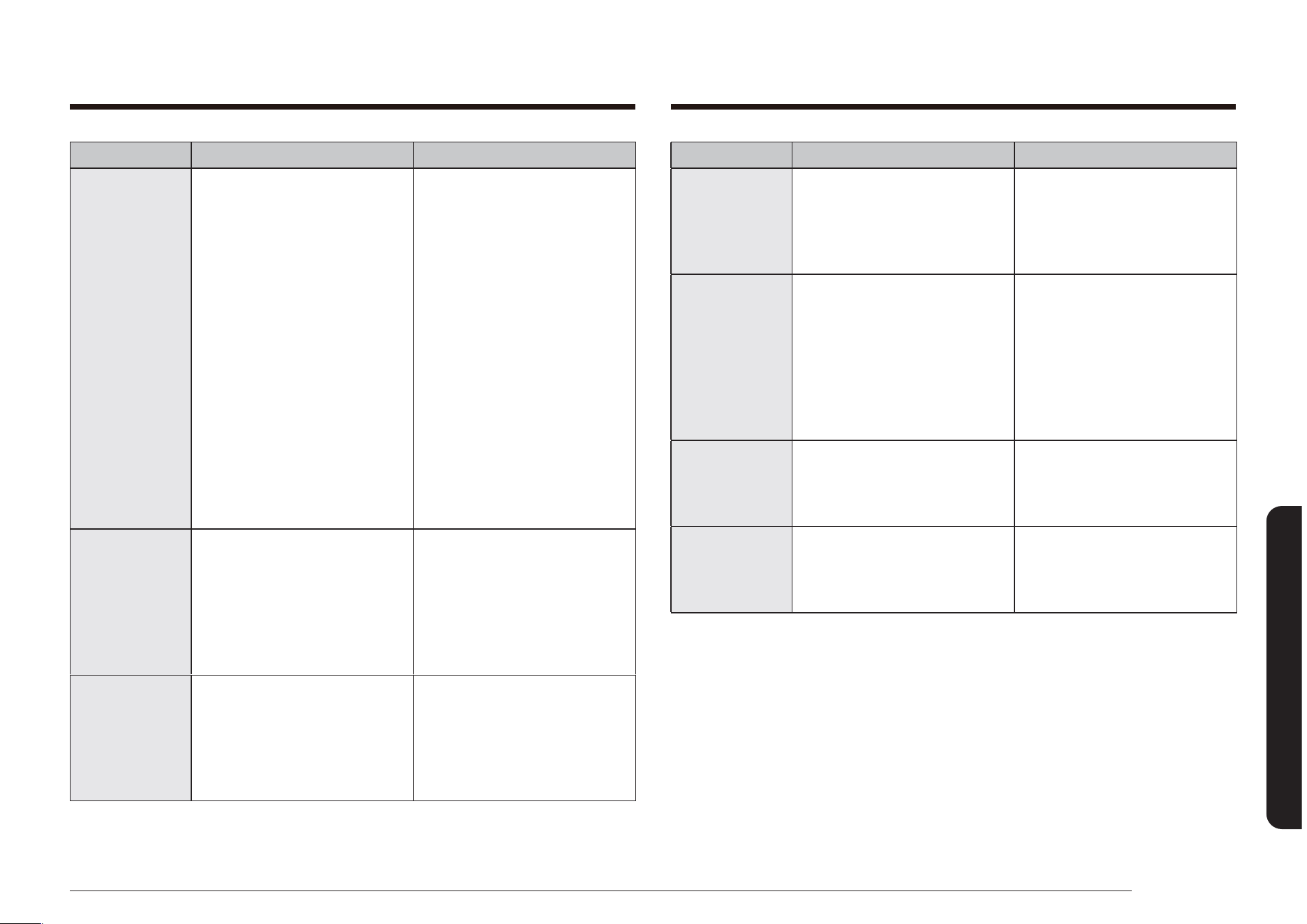
Français 79
Dépannage
PROBLÈME CAUSE POSSIBLE SOLUTION
Odeur forte. Cette odeur est provisoire. Il est normal de constater une
odeur provenant de l'isolation
de la cavité du four lors des
premières utilisations de
votre four.
Vous avez des
difcultés à
faire glisser les
grilles du four.
À l'aide de papier absorbant
imbibé d'huile végétale,
essuyez les bords des grilles
du four. Les grilles ternissent
et glissent plus difcilement
si vous les laissez dans le
four durant un cycle d'auto-
nettoyage.
Bruit au niveau
du ventilateur
.
Ceci est tout à fait normal. Le ventilateur de convection
se poursuit jusqu'à ce que la
fonction s'arrête ou la porte
est ouverte.
Le ventilateur
de convection
ne fonctionne
pas
.
Le ventilateur s'allume
automatiquement lorsque le
four atteint la température de
préchauffe.
PROBLÈME CAUSE POSSIBLE SOLUTION
Le four est
toujours sale
après un
cycle d'auto-
nettoyage.
Une couche ne de poussière
ou de cendre est normale.
Elle peut être essuyée à l’aide
d’un chiffon humide.
Réglez le cycle d'auto-
nettoyage pour une durée
plus longue. Le cycle n'était
pas assez long pour brûler
toutes les saletés accumulées.
Pour des fours extrêmement
sales, il est nécessaire
de nettoyer à la main les
éclaboussures importantes
avant de démarrer un cycle
d'auto-nettoyage. Plusieurs
cycles d'auto-nettoyage
peuvent s'avérer nécessaire
an de complètement
nettoyer le four.
De la vapeur
ou de la fumée
s'échappent
en dessous
du tableau de
commande.
Ceci est tout à fait normal. La ventilation du four se
trouve ici. Lorsque vous
utilisez des fonctions de
convection ou vous faites
cuire ou rôtir plusieurs
aliments en même temps, plus
de vapeur s'échappe.
Odeur de brûlé
ou d'huile
provenant de
la ventilation.
Ceci est normal pour un four
neuf et l'odeur disparaîtra
dans les 30 minutes après le
démarrage du premier cycle
de cuisson.
Pour accélérer la disparition
de ce phénomène,
programmez un cycle
d'auto-nettoyage d'une durée
minimale de 3 heures. (Voir
pages 72 et 73.)
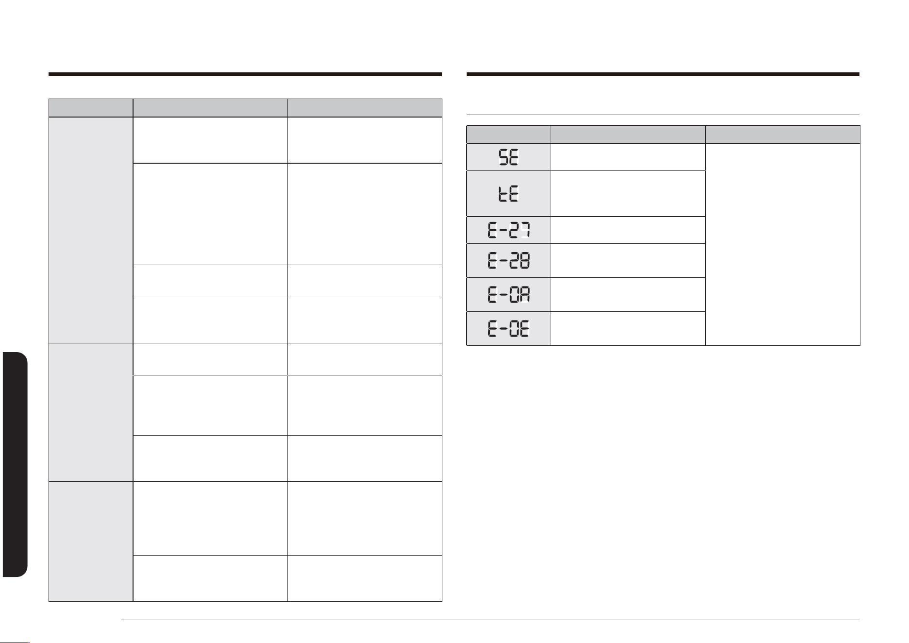
80 Français
Dépannage
Dépannage
Dépannage et codes d'erreur
CODE SIGNIFICATION SOLUTION
Touche court-circuitée Appuyez sur la touche OFF/
CLEAR (ARRÊT/EFFACER) et
redémarrez le four.
Si le problème persiste,
coupez l’alimentation
de la cuisinière pendant
30 secondes puis rétablissez-
la.
Si le problème n’est pas
résolu, contactez le service
technique. Reportez-vous au
bas de ce tableau.
Veriez les signaux de la
carte de circuit imprime
tactile.
Capteur du four coupé
Capteur du four court-circuité
Surchauffe du four
Erreur de verrouillage de la
porte
Si un code non répertorié ci-dessus s'afche, ou si les solutions suggérées ne
sufsent pas à résoudre le problème, appelez le 1-800-SAMSUNG (726-7864).
PROBLÈME CAUSE POSSIBLE SOLUTION
Le tiroir
chauffe-plat
ne fonctionne
pas (modèle
NX58*565**
*).
Les commandes n'ont pas été
correctement réglées.
Réinitialisez les commandes
comme décrit aux pages
58.
La fonction d'auto-nettoyage
ou Sabbath (Shabbat) est en
cours d'utilisation.
Le tiroir chauffe-plat ne
fonctionne pas pendant
l'exécution d'une de
ces fonctions. Essayez
ultérieurement lorsque la
fonction sera terminée ou
annulée.
Les commandes du four ont
été verrouillées.
Déverrouillez les commandes
et essayez de nouveau.
Un fusible a grillé ou le
disjoncteur a été déclenché.
Remplacez le fusible grillé
ou remettez le disjoncteur
déclenché en marche.
Condensation
excessive
dans le tiroir
chauffe-plat
(modèle
NX58*565**
*).
La température réglée est
trop importante.
Voir page 58.
Les aliments à maintenir au
chaud ne sont pas couverts
d'un couvercle ou de papier
aluminium.
Couvrez les aliments d'un
couvercle ou de papier
aluminium.
Vous essayez de chauffer des
liquides.
Du liquide ne devrait pas
être réchauffé dans le tiroir.
Retirez des liquides.
Le tiroir
chauffe-plat
ou le tiroir de
rangement
ne glisse pas
correctement
ou se bloque.
Le tiroir n'est pas
correctement aligné avec les
rails du plateau tournant à
extension complète ou les
guidages en nylon.
Retirez et remplacez le tiroir.
(Voir pages 69 et 70.)
Le contenu dans le tiroir est
trop lourd.
Réduisez le poids et/ou
redistribuez le contenu dans
le tiroir.

Français 81
Garantie
Pendant la période de garantie applicable, le produit sera réparé, remplacé ou remboursé à la
valeur de son prix d'achat, à la seule discrétion de SAMSUNG. SAMSUNG peut être amenée à
utiliser des pièces neuves ou reconditionnées lors de la réparation du produit, ou à remplacer
le produit par un produit neuf ou reconditionné. Les pièces et produits de rechange sont
garantis pendant la partie restante de la garantie initiale du produit ou alors pendant quatre-
vingt-dix (90) jours, selon la période qui est la plus longue. Toute pièce ou tout produit
remplacé devient la propriété de SAMSUNG et vous devez les restituer à SAMSUNG.
La présente garantie limitée couvre les défauts de fabrication au niveau des pièces et de
la main-d'œuvre survenant dans le cadre d'un usage domestique normal, non commercial
de ce produit et ne couvre pas les situations suivantes : dommages survenant au cours de
l’expédition, la livraison, l’installation et l'utilisation de l'appareil qui serait contraire au but
auquel il était destiné ; dommages causés par une modication ou altération non autorisée
du produit ; produits dont le numéro de série initial apposé en usine a été effacé, déformé,
modié d'une quelconque façon ou est illisible ; dommages de nature esthétique notamment
les rayures, piqûres, éclats et autres dommages sur la nition du produit ; dommages causés
par un abus, un usage inapproprié, des infestations d'insectes, un accident, un incendie,
des inondations, ou d'autres catastrophes naturelles ; dommages causés par l'utilisation
de matériel, utilitaires, services, pièces, fournitures, accessoires, applications, installations,
réparations, câblage externe ou connecteurs non fournis ou non autorisés par SAMSUNG ;
dommages causés par un courant de phase ou une tension électrique incorrect(e), des
uctuations et surtensions ; dommages causés par le non-respect des instructions
d'utilisation et de maintenance du produit ; instructions à domicile sur la bonne utilisation
de votre produit ; et interventions visant à corriger une installation qui n'est pas conforme
aux normes d'électricité et de plomberie ou à corriger les raccordements électriques ou
de plomberie du domicile (c.-à-d. câblage du domicile, fusibles, ou tuyaux d'arrivée d'eau).
En outre, la présente garantie limitée ne prend pas en charge les dommages de la table
de cuisson vitrée causés par (i) l'utilisation de produits et de tampons nettoyants non
recommandés ou (ii) les éclaboussures durcies de sucre ou de plastique fondu qui n'auraient
pas été nettoyées selon les instructions fournies dans le manuel d'entretien et d'utilisation.
Le coût des réparations ou du remplacement dans de telles circonstances exclues sera à la
charge au client.
Les interventions par un réparateur agréé visant à expliquer les fonctions de l'appareil
ou les procédures de maintenance ou d'installation ne sont pas couvertes par la présente
garantie limitée. Veuillez communiquer avec SAMSUNG au numéro indiqué ci-dessous pour
obtenir de l'aide sur l'un de ces problèmes.
Garantie (États-Unis)
VEUILLEZ NE PAS JETER.
CUISINIÈRE À GAZ
GARANTIE LIMITÉE POUR L'ACHETEUR INITIAL AVEC PREUVE D'ACHAT
Ce produit de la marque SAMSUNG, fourni et distribué par SAMSUNG ELECTRONICS
AMERICA INC. (SAMSUNG) et livré neuf, dans son carton d'origine à l'acheteur et
consommateur initial, s'accompagne d'une garantie de SAMSUNG contre tout vice de
fabrication au niveau des pièces et de la main d'œuvre pendant une période limitée,
commençant à la date d'achat initial, de :
Un (1) an (pièces et main d'œuvre)
La présente garantie limitée ne s'applique qu'aux produits achetés et utilisés au sein des
États-Unis et ayant été installés, utilisés et entretenus conformément aux instructions
jointes ou fournies avec le produit. Pour se prévaloir du service de garantie, l'acheteur doit
contacter SAMSUNG à l'adresse ou au numéro de téléphone fournis ci-dessous an d'établir
les procédures relatives au diagnostic et à l'intervention nécessaire. Le service de garantie
ne peut être assuré que par un service technique agréé SAMSUNG. La facture datée et
originale doit être présentée sur demande comme preuve d'achat à SAMSUNG ou au service
technique agréé SAMSUNG pour pouvoir bénécier du service de garantie.
SAMSUNG vous assure un service de réparation à domicile au sein des États-Unis contigus
pendant la période de garantie et ce gratuitement, sous réserve de disponibilité des agents
agréés du service technique SAMSUNG dans la zone géographique du client. Si le service de
réparation à domicile n'est pas disponible, SAMSUNG peut organiser, à sa seule discrétion,
le transport du produit vers ou depuis un centre technique agréé. Si le produit se trouve
dans une zone où la réparation par un agent agréé du service technique SAMSUNG n'est pas
disponible, il se peut que vous deviez vous acquitter de frais de transport ou apporter le
produit dans un service technique agréé SAMSUNG pour faire la réparation.
Pour bénécier du service de réparation à domicile, vous devez veiller à ce que le produit
soit dépourvu d'obstacle accessible à l'agent de maintenance.

82 Français
Garantie
Garantie
Pour bénécier du service de garantie, contactez SAMSUNG à l'adresse suivante :
Samsung Electronics America, Inc.
85 Challenger Road
Ridgeeld Park, NJ 07660
1-800-SAMSUNG (726-7864) et www.samsung.com/us/support
Enregistrement
Veuillez enregistrer votre produit sur www.samsung.com/register.
Questions
Pour les questions sur les fonctions, le fonctionnement/la performance, les pièces, les
accessoires, ou le service, appelez le 1-800-SAMSUNG (726-7864), ou consultez le
site internet www.samsung.com/us/support.
Modèle # Série #
Veuillez joindre votre facture (ou une copie) à ce manuel. Vous pouvez en avoir
besoin, ainsi que du modèle et numéro de série, si vous devez appeler l'assistance.
EXCLUSION DE GARANTIES IMPLICITES
LES GARANTIES IMPLICITES, Y COMPRIS LES GARANTIES IMPLICITES DE QUALITÉ
MARCHANDE OU D'APTITUDE À UN USAGE PARTICULIER, SONT LIMITÉES À UN
AN OU À LA PLUS COURTE PÉRIODE AUTORISÉE PAR LA LOI. Certains États et
certaines juridictions n'autorisent pas de limitations quant à la durée des garanties
implicites ; il se peut par conséquent que les limitations et exclusions énoncées
ci-dessus ne s'appliquent pas à votre cas. Cette garantie vous confère des droits
spéciques ; il est donc possible que vous bénéciez d’autres droits qui varieront
d’une juridiction à une autre.
LIMITATION DE RECOURS
VOTRE SEUL ET EXCLUSIF RECOURS EST LA RÉPARATION DU PRODUIT, LE
REMPLACEMENT DU PRODUIT, OU LE REMBOURSEMENT DE SON PRIX D'ACHAT
À LA SEULE DISCRÉTION DE SAMSUNG, COMME PROPOSÉ DANS LA PRÉSENTE
GARANTIE LIMITÉE. SAMSUNG NE SAURA ÊTRE TENU RESPONSABLE EN CAS DE
DOMMAGES ACCESSOIRES, INDIRECTS OU SPÉCIAUX, NOTAMMENT MAIS SANS
POUR AUTANT S'Y LIMITER LE TEMPS PRIS SUR LE TRAVAIL, LES FRAIS D'HÔTELS
ET/OU REPAS EN RESTAURANT, LES DÉPENSES DE RÉNOVATION, LA PERTE DE
BÉNÉFICES, DE REVENUS OU DE FONDS COMMERCIAL OU L'IMPOSSIBILITÉ DE
RÉALISER LES ÉCONOMIES ESCOMPTÉES, QUELLE QUE SOIT LA BASE JURIDIQUE
INVOQUÉE POUR JUSTIFIER L'ASSERTION, ET MÊME SI SAMSUNG A ÉTÉ AVISÉ
DE LA POSSIBILITÉ DE TELS DOMMAGES. Certains États et certaines juridictions
n'autorisent pas l'exclusion ou les limitations pour dommages accessoires ou
indirects. Il est donc possible que les limitations ou exclusions ci-dessus ne
s'appliquent pas à votre cas. Cette garantie vous confère des droits spéciques ;
il est donc possible que vous bénéciez d’autres droits qui varieront d’une
juridiction à une autre.
SAMSUNG ne garantit pas un fonctionnement continu ou sans erreur de ce produit.
Samsung ne sera tenu d'honorer aucune autre garantie donnée par toute autre
personne, rme ou société en regard de ce produit.

Français 83
Garantie
La société SAMSUNG prendra en charge, à sa convenance, la réparation ou le remplacement
du produit à ses frais tel que stipulé dans les présentes conditions et procédera au
remplacement ou au changement des pièces ou des produits si ces derniers s'avèrent
défectueux dans la limite de la période de garantie mentionnée précédemment. Toute pièce
ou tout produit remplacé devient la propriété de SAMSUNG et doit lui être restitué. Les
pièces et produits de rechange sont protégés pour le reste de la période de garantie initiale
ou pour quatre-vingt-dix (90) jours, selon l’éventualité la plus éloignée.
La présente garantie limitée ne peut s'étendre aux cas d'alimentation ou de tension
électrique incorrectes, d'ampoules inappropriées, d'installations électriques défectueuses,
aux cas de demandes d'assistance pour information ou de résolutions d'erreurs
d'installation. En outre, elle ne prend pas en charge l'endommagement de la table de cuisson
qui résulterait de l'utilisation de produits et de tampons nettoyants non recommandés,
l'endommagement de la table de cuisson provoqué par des éclaboussures durcies de sucre
ou de plastique fondu qui n'auraient pas été nettoyées selon les instructions fournies dans
le manuel d'entretien et d'utilisation. SAMSUNG ne garantit pas un fonctionnement continu
ou sans erreur de ce produit.
À L'EXCEPTION DE CELLES EXPOSÉES PAR LA PRÉSENTE, IL N'EXISTE AUCUNE AUTRE
GARANTIE SUR CE PRODUIT, QU'ELLE SOIT EXPRESSE OU IMPLICITE, ET SAMSUNG REJETTE
TOUTE AUTRE GARANTIE Y COMPRIS, MAIS SANS S'Y LIMITER, TOUTE GARANTIE IMPLICITE
RELATIVE À LA QUALITÉ MARCHANDE, À L'ABSENCE DE CONTREFAÇON OU À
L'ADAPTATION À UN USAGE PARTICULIER. SAMSUNG NE SERA TENU D’HONORER
AUCUNE AUTRE GARANTIE DONNÉE PAR UNE PERSONNE, UNE FIRME OU UNE SOCIÉTÉ
QUELCONQUE
EN REGARD DE CE PRODUIT. SAMSUNG N'ENDOSSE PAS LA RESPONSABILITÉ EN CAS DE
PERTE DE REVENU, DE MANQUE À GAGNER, D'INCAPACITÉ À RÉALISER DES ÉCONOMIES
OU TOUT AUTRE AVANTAGE FINANCIER, OU EN CAS DE DOMMAGE RÉSULTANT DE
L'UTILISATION OU DE LA MAUVAISE UTILISATION DE CET APPAREIL OU D'UNE INCAPACITÉ
À UTILISER CET APPAREIL,
Garantie (CANADA)
VEUILLEZ NE PAS JETER.
CUISINIÈRE À GAZ
GARANTIE LIMITÉE À L'ACHETEUR INITIAL
Ce produit de la marque SAMSUNG, fourni, distribué par SAMSUNG ELECTRONICS CANADA
INC. (SAMSUNG) et livré neuf, s'accompagne d'une garantie de SAMSUNG contre tout vice de
fabrication au niveau des pièces et de la main d'œuvre pendant une période limitée de :
Un (1) an (pièces et main d'œuvre)
Cette garantie limitée prend effet le jour de l'achat initial et elle est uniquement valable
pour les produits achetés et utilisés au Canada. Pour se prévaloir du service de garantie,
l'acheteur doit contacter SAMSUNG an d'établir les procédures relatives au diagnostic et à
l'intervention nécessaire. Le service de garantie ne peut être effectué que par un centre de
service SAMSUNG agréé, et tout autre service non autorisé annule cette garantie. Lors de
la remise d'un produit défectueux à SAMSUNG ou à un centre de service SAMSUNG agréé,
l'acquéreur est tenu de présenter le coupon d'achat d'origine à la demande des intéressés
à titre de preuve d'achat. Samsung vous assure un service à domicile pendant la période
de garantie un an (1) sans frais supplémentaires en fonction des disponibilités à l'intérieur
des États contigus du Canada. Le service à domicile n'est pas disponible pour toutes les
zones. Pour en bénécier, vous devez veiller à ce que le produit soit accessible pour l'agent
de maintenance. En cas d'indisponibilité de ce service, Samsung pourra choisir le moyen
de transport adéquat pour acheminer ou renvoyer l'appareil vers et depuis un centre de
service agréé.

84 Français
Garantie
Garantie
Enregistrement
Veuillez enregistrer votre produit sur www.samsung.com/register.
Questions
Pour les questions sur les fonctions, le fonctionnement/la performance, les pièces, les
accessoires, ou le service, appelez le 1-800-SAMSUNG (726-7864), ou consultez le site
internet www.samsung.com/ca/support (English) ou www.samsung.com/ca_fr/support
(French).
Modèle # Série #
Veuillez joindre votre facture (ou une copie) à ce manuel. Vous pouvez en avoir
besoin, ainsi que du modèle et numéro de série, si vous devez appeler l'assistance.
QUELLE QUE SOIT LA BASE LÉGALE SUR LAQUELLE REPOSE LA PLAINTE, ET MÊME
SI SAMSUNG A ÉTÉ AVERTI DE L'ÉVENTUALITÉ DE TELS DOMMAGES. TOUT TYPE DE
COMPENSATION EXIGÉ AUPRÈS DE SAMSUNG NE DEVRA EN AUCUN CAS EXCÉDER LE PRIX
D’ACHAT DU PRODUIT VENDU PAR SAMSUNG ET À L’ORIGINE DES DOMMAGES ALLÉGUÉS.
SANS LIMITATION AUX DISPOSITIONS SUSDITES, L’ACHETEUR ASSUME TOUS LES RISQUES
ET TOUTES LES RESPONSABILITÉS EN CAS DE PERTE, DE DOMMAGES OU DE BLESSURES
ÉVENTUELLES INFLIGÉS À L’ACHETEUR ET AUX BIENS DE CELUI-CI ET À TOUTE AUTRE
PERSONNE ET AUX BIENS DE CELLE-CI RÉSULTANT DE L'UTILISATION OU DE LA MAUVAISE
UTILISATION DE L'APPAREIL OU DE L'INCAPACITÉ À L'UTILISER. CETTE GARANTIE LIMITÉE
N’EST VALABLE POUR PERSONNE D’AUTRE QUE L’ACHETEUR INITIAL DU PRODUIT, N’EST
PAS TRANSFÉRABLE ET ÉNONCE VOTRE RECOURS EXCLUSIF.
Certaines provinces ou territoires peuvent autoriser ou non des limitations quant à la
durée des garanties implicites ni l’exclusion ou la limitation de dommages accessoires ou
indirects ; il se peut par conséquent que les limitations et exclusions énoncées ci-dessus
ne s'appliquent pas à votre cas. Cette garantie vous confère des droits légaux spéciques.
Vous pouvez également avoir d'autres droits qui varient d'un Etat à l'autre et d'une province
à l'autre. Les pièces remplacées par l’utilisateur peuvent être envoyées au client pour
réparation. Si nécessaire, un ingénieur du service d’assistance pourra être envoyé pour
effectuer des réparations.
Pour bénécier d'un service d'assistance couvert par votre garantie, contactez SAMSUNG à
l'adresse suivante :
Samsung Electronics Canada Inc.
2050 Derry Road West, Mississauga, Ontario L5N 0B9 Canada
1-800-SAMSUNG (726-7864) et www.samsung.com/ca/support (English),
www.samsung.com/ca_fr/support (French)

Veuillez noter que la garantie Samsung n’inclut pas les déplacements du service après-vente pour expliquer le fonctionnement de l’appareil, corriger une installation non
correcte ou exécuter des travaux de nettoyage ou d’entretien réguliers.
UNE QUESTION ? UN COMMENTAIRE ?
PAYS N° DE TÉLÉPHONE SITE INTERNET
U.S.A
Consumer Electronics
1-800-SAMSUNG (726-7864) www.samsung.com/us/support
CANADA 1-800-SAMSUNG (726-7864)
www.samsung.com/ca/support (English)
www.samsung.com/ca_fr/support (French)
DG68-00526A-15
Scannez le code QR* ou rendez-vous
sur le site www.samsung.com/spsn
pour voir nos vidéos et
démonstrations en direct d’utilisation.
* Requiert l’installation d’un lecteur sur
votre smartphone