Loading ...
Loading ...
Loading ...
-7-
ATTENTION: DO NOT vent under any porch, deck, awning, or in any semi enclosed or roofed area. Doing so
may result in unpredictable airow at the vent cap under certain conditions and can affect the performance
of your stove, as well as, other unforeseeable issues.
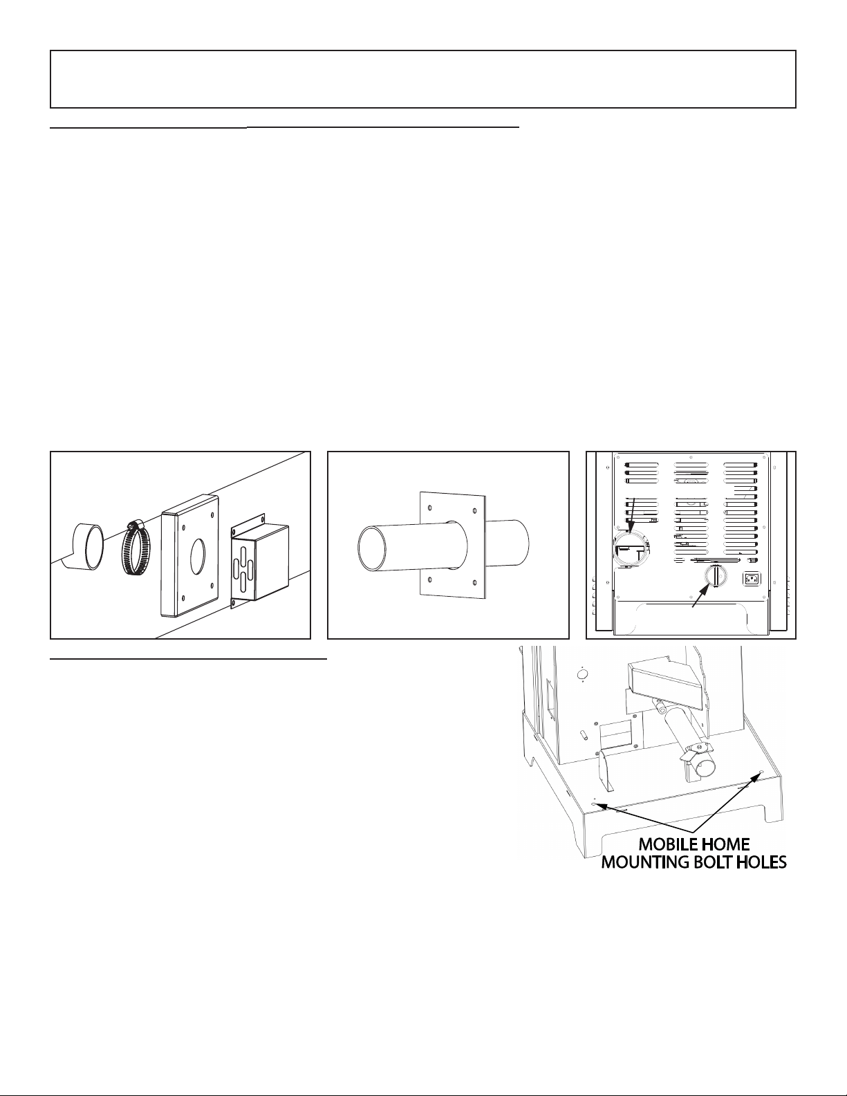
SPECIAL MOBILE HOME REQUIREMENTS
• WARNING! - Do not install in a sleeping room
• CAUTION! - The structural integrity of the mobile home oor,
wall, and ceiling/roof must be maintained.
In addition to the previously detailed installation requirements,
mobile home installations must meet the following requirements:
• This stove must be securely fastened to the oor of the mobile
home through the two holes in the rear of the stove using 2, 1/4”
lag bolts that are long enough to go through both a hearth
pad, if used, and the oor of the home.
• The heater must be electrically grounded to the steel chassis
of the mobile home with 8 GA copper wire using a serrated or
star washer to penetrate paint or protective coating to ensure
grounding.
• Vent must be 3 or 4-inch “PL” Vent and must extend a minimum
or 36” (914 mm) above the roof line of the mobile home and must be installed using a certied ceiling re stop
and rain cap.
• When moving your mobile home, all exterior venting must be removed while the mobile home is being
relocated. After relocation, all venting must be reinstalled and securely fastened.
• Outside Air is mandatory for mobile home installation. See Outside Air Supply section and your dealer for
purchasing.
• Check with your local building ofcials as other codes may apply.
69FAK OUTSIDE AIR SUPPLY (OPTIONAL, UNLESS INSTALLING IN A MOBILE HOME)
Depending on your location and home construction, outside air may be necessary for optimal performance.
1. With the stove in the operating position, mark and drill a hole to accommodate the 2” exible hose.
2. Insert the hose through the wall and attach the Outside Cover with one of the 2” hose clamps provided.
3. Then attach the Outside Cover to the outside wall.
4. Next, attach the Rodent Cover to the Outside Cover using four (4) of the #10 x 3/4 screws supplied.
5. On the inside of the home, slide the Inside Plate over the tube then attach to the wall with the four drywall
anchors and screws provided.
6. On the Air Inlet Tube coming out of the rebox, there is a cap that must have four (4), 5/32” (0.156) diameter
holes drilled in it for the fresh air installation. The cap is on the front side of the tube just under the burnpot.
Remove burnpot. Using a long screwdriver or equivalent, knock the cap off by inserting it from the back of
the stove and pecking with a hammer. Drill holes, then replace cap and burnpot.
7. Attach one of the 2” ex hoses to the backside of the rebox, then to air inlet pipe at the back of the stove
as shown.
8. Stretch the 2” ex hose to the air inlet on the back of the stove. Attach using the other 2” hose clamp. The
hose will extend up to 4 feet in length.
Exhaust Outlet
Fresh Air Intake
Figure 1
B
C
E
A
Figure 2
A
D
Loading ...
Loading ...
Loading ...