Loading ...
Loading ...
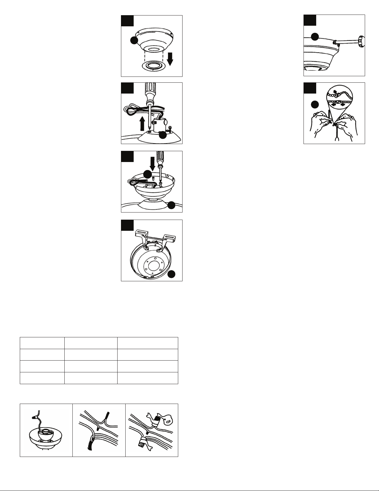
6. If necessary, remove every other screw
and lock washer from top of motor
housing. (These screws may already be in
a hardware pack.)
7. Pull wires through the canopy hole (C)
and attach canopy to motor housing using
the 3 screws and 3 lock washers (FF)
provided.
5. If using hugger mount installation,
remove rubber washer from bottom of the
canopy (C).
Note: Flange cover is not used with this
type of installation.
5
6
7
I
H
8. Temporarily hang fan onto the tab on the
mounting bracket (B) until wiring is
complete. Use one of the non-slotted
holes in the canopy (C).
When wires are matched up, connect them by twisting frayed ends
together; Screw wire connectors(3 are provided) onto the tops of the
twisted wires; Tighten them with electrical tape.
WARNING: Be sure no bare wire or wire strands are visible after
making connection. Place green and white connections on opposite
side of box from the black and blue (if applicable) connections.
8
H
9. Wiring Instructions:
IMPORTANT: If you are not sure if the e_lectrical outlet box and fan are
grounded, contact a licensed electrician for advice.They must be
grounded for safe operation. WARNING: To avoid possible electrical
shock, be sure electricity is turned off at the main fuse box before
wiring.
Your outlet box should have 3 wires. If they are not there, contact a
certied electrician to help set this part up.Match up and connect
wires from the ceiling fan to the wires from your outlet box according
to the chart below:
C
Connect with
wire connector
On fan
Ground & ground
Motor, live
Neutral & neutral
2 ground wires (green)
Motor wire (black)
Neutral wire (white)
In outlet box
Live wire (typically black)
Neutral wire (white)
Ground wire
(typically copper or green)
10. Temporarily lift canopy (C) to mounting
bracket (B) to determine which screws align
with slotted holes in canopy (C) and partially
loosen these screws. Remove the other two
screws. Raise canopy (C) to mounting
bracket (B), aligning slotted holes in canopy
(C) to lock.Insert the other two screws in
nonslotted holes. Tighten, all screws
securely.
10
C
11. Assemble decorative fob chains (E) from
hardware bag to fan and light kit pull chains.
Insert end chain into chain coupling. Check
that chains are held by lightly pulling both
chains in coupling.
11
E
Operation:
Turn fan on/off & select fan speed
Restore power to ceiling fan and test for propeer
operation.
The fan pull chain controls the fan speed settings:
1. Turn on the fan at high speed;
2. Turn on the fan at medium speed;
3. Turn on the fan at low speed;
4. Turn off the fan.
Forward and reverse direction function:
This ceiling fan is equipped with a Reverse Switch for downward or
upward air-ow.
NOTE: Do not use the Reverse Switch when the fan blades are in
motion.
Forward function
On this setting, the fan will turn counterclockwise to create a cooling
effect. Use this function during warmer weather to circulate the hot air
away from your living space.
Reverse function
On this setting, the fan will turn clockwise. Use this function during
cooler weather to re-circulate warm air.
FF
Loading ...