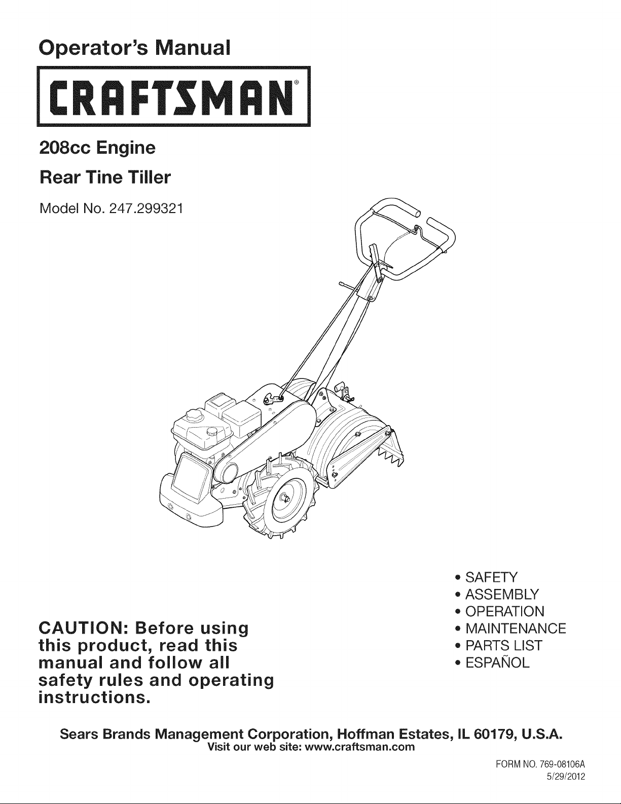
Operator's Manual
I:Rl FI'SlVl N
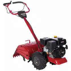
208cc Engine
Rear Tine Tiller
Model No. 247.299321
CAUTION: Before using
this product, read this
manual and follow aJl
safety rules and operating
instructions.
* SAFETY
* ASSEMBLY
* OPERATION
* MAINTENANCE
* PARTS LIST
* ESPANOL
Sears Brands Management Corporation, Hoffman Estates, IL 60179, U.S.A.
Visit our web site: www.craftsman.com
FORMNO.769-08106A
5/29/2012
WarrantyStatement..................................Pac
Safetyinstructions....................................Pac
Assembly..................................................Pac
Operation..................................................Pac
ServiceandMaintenance.........................Pac
Off-SeasonStorage..................................Pac
Troubleshooting........................................Pac
e2
es3-6
es7-10
es11-16
es17-22
e23
e24
PartsList...................................................Page26-40
Labels.......................................................Page41
RepairProtectionAgreement...................Page44
Espa_ol.....................................................Page45
ServiceNumbers......................................BackCover
CRAFTSMAN TWO YEAR FULL WARRANTY
FORTWOYEARSfromthe dateof purchase,this productis warrantedagainstanydefectsin materialor workmanship,A defectiveproductwill
receivefree repairor replacementif repairis unavailable,
For warranty coverage details to obtain free repair or replacement,visit the web site: www.craftsman.com
This warranty covers ONLYdefects in material andworkmanship. Warranty coverage does NOT include:
• Expendableitemsthat can wearoutfromnormalusewithinthewarrantyperiod,suchas the blades,tines, orbelts.
• Productdamageresultingfromuserattemptsat productmodificationor repairor caused by productaccessories.
• Repairsnecessarybecauseof accidentor failureto operateor maintainthe productaccordingto all suppliedinstructions.
• Preventivemaintenance,or repairsnecessarydueto improperfuel mixture,contaminatedor stalefuel.
Thiswarrantyis void if this productis everusedwhile providingcommercialservicesor if rentedto anotherperson.
Thiswarrantygivesyou specificlegal rights,and you mayalso haveotherrights whichvary from stateto state.
Sears Brands Management Corporation, Hoffman Estates, IL 60179
EngineSeries: 208cc
EngineOilType: 10w30
EngineOilCapacity: 20ounces
Fuel: UnleadedGasoline
SparkPlug: F6RTC
SparkPlugGap: .030"
ModelNumber.................................................................
Serial Number .................................................................
Dateof Purchase.............................................................
Recordthe modelnumber,serialnumber
anddateof purchaseabove
© Sears Brands,LLC 2
Thissymbolpointsout importantsafetyinstructionswhich,if not
followed,couldendangerthe personalsafetyand/orpropertyof
yourselfandothers. Readand followall instructionsin thismanual
beforeattemptingto operatethis machine.Failureto complywith
theseinstructionsmay resultin personalinjury.Whenyou seethis
symbol,HEEDITSWARNING!
CALIFORNIA PROPOSITION 65
EngineExhaust,someof itsconstituents,andcertainvehicle
componentscontainoremit chemicalsknownto Stateof California
to cause cancerand birthdefectsorother reproductiveharm. Bat-
tery posts,terminals,andrelatedaccessoriescontainleadand lead
compounds,chemicalsknownto the Stateof Californiato cause
cancerandreproductiveharm.Washhandsafterhandling.
Thismachinewasbuilt to be operatedaccordingto the safeopera-
tion practicesin thismanual.As withany type of powerequipment,
carelessnessor error on the part of the operatorcan resultin
seriousinjury.Thismachineis capableof amputatingfingers,hands,
toesandfeetandthrowingdebris.Failureto observethe following
safetyinstructionscouldresultin seriousinjuryordeath.
Your Responsibility--Restrictthe use of this powermachineto
personswho read,understandandfollowthewarningsand instruc-
tionsin thismanualandon the machine.
SAVETHESEINSTRUCTIONS!
TRAINING
• Read,understand,andfollowall instructionson the machineand
in themanual(s)beforeattemptingto assembleandoperate.
Keepthis manualina safeplacefor futureand regularreference
andfor orderingreplacementparts.
• Readthe Operator'sManualand followallwarningsand safety
instructions.Failureto doso can resultin seriousinjuryto the
operatorand/or bystanders.Forquestions,call 1-800-4MY-HOME.
• Be familiarwith all controlsand their properoperation.Knowhow
to stop the machineanddisengagethemquickly.
• Neverallowchildrenunder14yearsof age to operatethis
machine.Children14andover shouldreadandunderstandthe
instructionsand safe operationpracticesin thismanualandon
the machineandbe trainedandsupervisedby an adult.
• Neverallowadultsto operatethis machinewithoutproper
instruction.
• Keepbystanders,pets,and childrenat least 75 feetfrom the
machinewhile it is in operation.Stopmachineif anyoneenters
the area.
• Neverrun an engine indoorsor in a poorlyventilatedarea.Engine
exhaustcontainscarbonmonoxide,an odorlessand deadlygas.
PREPARATION
• Thoroughlyinspecttheareawherethe equipmentis to be used.
Removeall rocks,bottles,cans,or otherforeignobjectswhich
could be pickedup or thrownand cause personalinjuryor
damageto the machine.
• Alwayswear safetyglassesor safetygogglesduringoperation
andwhile performingan adjustmentor repair,to protectyour
eyes.Thrownobjectswhich ricochetcan causeseriousinjuryto
the eyes.
• Wearsturdy,rough-soledwork shoesand close-fittingslacksand
shirts.Loosefittingclothesor jewelrycan becaughtin movable
parts.Neveroperatethis machinein bare feet or sandals.
• Beforestarting,checkallboltsandscrewsfor propertightnessto
besurethe machineis in safe workingcondition.Also,visually
inspectmachinefor any damageat frequentintervals.
• Disengageclutchleversandshift (if provided)into neutral("N")
beforestartingtheengine.
• Neverleavethis machineunattendedwiththe engine running.
• Neverattemptto make anyadjustmentswhilethe engineis
running,exceptwherespecificallyrecommendedin the operator's
manual.
• Maintainor replacesafetyandinstructionslabels,as necessary.
3
Safe Handling of Gasoline:
Toavoidpersonalinjuryor propertydamageuseextremecare in
handlinggasoline.Gasolineis extremelyflammableandthe vaporsare
explosive.Seriouspersonalinjurycan occurwhengasolineis spilled
onyourselfor yourclotheswhichcan ignite.Washyour skinand
changeclothesimmediately.
• Use onlyan approvedgasolinecontainer.
• Neverfill containersinsidea vehicleor ona truckor trailerbed
witha plasticliner.Alwaysplacecontainersonthe groundaway
fromyour vehiclebeforefilling.
• Whenpractical,removegas-poweredequipmentfromthe truck
ortrailerand refueliton the ground.If this is notpossible,then
refuelsuchequipmenton a trailerwith a portablecontainer,rather
thanfrom a gasolinedispensernozzle.
• Keepthe nozzleincontactwiththe rimof the fuel tank or
containeropeningat alltimes untilfuelingis complete.Do not use
a nozzlelock-opendevice.
• Extinguishall cigarettes,cigars,pipesandother sourcesof
ignition.
• Neverfuel machineindoors.
• Neverremovegas capor addfuel whilethe engineishot or run-
ning.Allowengineto cool at leasttwo minutesbeforerefueling.
• Neveroverfill fueltank. Fill tankto nomorethan1/2inchbelow
bottomof filler neckto allowspacefor fuel expansion.
• Replacegasolinecapandtightensecurely.
• If gasolineisspilled,wipe itoff theengineandequipment.Move
unitto anotherarea.Wait5 minutesbeforestartingthe engine.
• To reducefire hazards,keepmachinefreeof grass, leaves,or
otherdebrisbuild-up.Cleanupoil or fuel spillageand removeany
fuel soakeddebris.
• Neverstorethe machineorfuel containerinsidewherethereis an
openflame,spark or pilotlightas on awaterheater,spaceheater,
furnace,clothesdryer or othergas appliances.
OPERATION
• Do not puthandsor feet near rotatingparts.Contactwith the
rotatingpartscan amputatehandsand feet.
• Do notoperatemachinewhileunderthe influenceof alcoholor
drugs.
• Neveroperatethis machinewithoutgood visibilityor light.Always
be sureof yourfootingand keepa firmholdonthe handles.
• Keepbystandersawayfromthe machinewhileit isinoperation.
Stopthe machineif anyoneentersthe area.
• Be carefulwhentilling in hard ground.Thetines maycatchin the
groundandpropelthe tillerforward.If this occurs,let goof the
handlebarsand do not restrainthe machine.
• Exerciseextremecautionwhenoperatingonor crossinggravel
surfaces.Stayalert for hiddenhazardsortraffic. Do notcarry
passengers.
• Neveroperatethe machineat hightransportspeedson hard or
slipperysurfaces.
• Exercisecautionto avoidslippingor falling.
• Lookdownand behindandusecare whenin reverseor pulling
machinetowardsyou.
• Start the engineaccordingto the instructionsfoundinthis manual
and keepfeetwell awayfromthe tinesat all times.
• After strikingaforeignobjector ifyour machineshouldstart mak-
ingan unusualnoiseor vibration,immediatelyshutthe engineoff.
Disconnectthe sparkplugwire,grounditagainstthe engineand
performthe followingsteps:
a. Inspectfor damage.
b. Repairor replaceanydamagedparts.
c. Checkfor anyloose partsandtightento assurecontinued
safeoperation.
• Disengageall clutchlevers(if fitted)and stopenginebeforeyou
leavethe operatingposition(behindthe handles).Waituntil
the tines cometo a completestopbeforeuncloggingthe tines,
makingany adjustments,or inspections.
• Neverrun an engineindoorsorina poorlyventilatedarea.Engine
exhaustcontainscarbonmonoxide,an odorlessand deadlygas.
• Mufflerand enginebecomehot andcancause a burn.Do not
touch.
• Usecautionwhentillingnear fences,buildingsand underground
utilities.Rotatingtines can causepropertydamageor personal
injury.
• Donot overloadmachinecapacityby attemptingto till soil too
deepat too fastof a rate.
• If the machineshouldstart makingan unusualnoiseor vibration,
stopthe engine,disconnectthe spark plugwire andgroundit
againstthe engine.Inspectthoroughlyfor damage.Repairany
damagebeforestartingandoperating.
• Keepall shields,guards,and safetydevicesin placeandoperat-
ing properly.
• Neverpick uporcarrymachinewhilethe engineis running.
• Useonly attachmentsandaccessoriesapprovedby the manu-
factureras listedin the PartsList pagesof this operator'smanual.
Failureto do so can resultin personalinjury.
• If situationsoccurwhichare notcoveredinthis manual,use care
andgoodjudgement.ContactCustomerSupportat 1-800-4MY-
HOMEfor assistanceandthe nameof thenearestservicedealer
MAINTENANCE & STORAGE
• Keepthe machine,attachmentsandaccessoriesin safeworking
order.
• Allowthe machineto coolat leastfiveminutesbeforestoring.
Nevertamperwithsafetydevices.Checktheirproperoperation
regularly.
• Checkboltsandscrewsfor propertightnessat frequentintervals
to keepthe machineinsafeworkingcondition.Also,visually
inspectmachineforany damage.
• Beforecleaning,repairing,or inspecting,stop the engineand
makecertainthetines and all movingpartshavestopped.
Disconnectthe sparkplug wireandgrounditagainstthe engineto
preventunintendedstarting.
4
• Do notchangethe enginegovernorsettingsor over-speedthe
engine.Thegovernorcontrolsthemaximumsafeoperatingspeed
of engine.
Maintainor replacesafetyand instructionlabels,as necessary.
Followthis manualfor safe loading,unloading,transporting,and
storageof thismachine.
Alwaysreferto theoperator'smanualfor importantdetailsif the
machineis to bestoredforan extendedperiod.
If thefuel tankhasto be drained,do this outdoors.
Observeproperdisposallawsandregulationsfor gas,oil, etc.to
protectthe environment.
Accordingto the ConsumerProductsSafetyCommission(CPSC)
andthe U.S.EnvironmentalProtectionAgency(EPA),thisproduct
hasan AverageUsefulLifeof seven(7)years,or 130 hoursof
operation.At the endof theAverageUsefulLifehavethe machine
inspectedannuallyby anauthorizedservicedealerto ensurethat
allmechanicaland safetysystemsareworkingproperlyandnot
wornexcessively.Failureto do so can resultinaccidents,injuries
ordeath.
DO NOT MODIFY ENGINE
Toavoidseriousinjuryor death, do not modifyenginein anyway.
Tamperingwiththe governorsettingcan leadto a runawayengineand
causeit to operateat unsafespeeds.Nevertamperwithfactorysetting
of enginegovernor.
NOTICE REGARDING EMISSIONS
Engineswhich are certifiedtocomplywithCaliforniaandfederal
EPAemissionregulationsfor SORE(SmallOff RoadEquipment)are
certifiedto operateon regularunleadedgasoline,and mayinclude
the followingemissioncontrolsystems:EngineModification(EM),
OxidizingCatalyst(CO), SecondaryAirInjection(SAI)and ThreeWay
Catalyst(TWO)if so equipped.
SPARK ARRESTOR
Thismachineis equippedwith an internalcombustionengineand
shouldnotbe usedon or near anyunimprovedforest-covered,
brushcoveredor grass-coveredlandunlessthe engine'sexhaust
systemis equippedwith a sparkarrestormeetingapplicablelocal or
statelaws (if any)
Ifa sparkarrestoris used, it shouldbe maintainedin effectiveworking
orderby theoperator.Inthe Stateof Californiathe aboveis required
bylaw (Section4442of the CaliforniaPublicResourcesCode).Other
statesmayhavesimilarlaws. Federallawsapplyon federallands.
A sparkarrestorfor the muffleris availablethroughyournearestSears
PartsandRepairServiceCenter.
SAFETY SYMBOLS
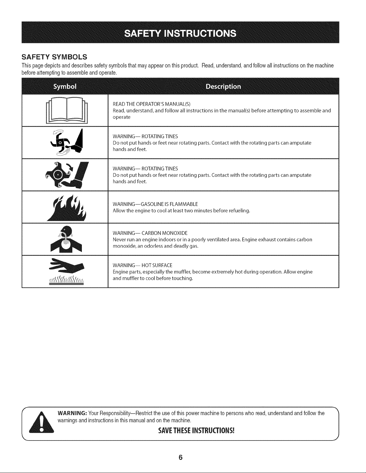
Thispagedepictsand describessafetysymbolsthatmayappearonthis product. Read,understand,and followall instructionson the machine
beforeattemptingto assembleandoperate.
i
i
READ THE OPERATOR'S MANUAL(S)
Read, understand, and follow all instructions in the manual(s) before attempting to assemble and
operate
WARNING-- ROTATING TINES
Do not put hands or feet near rotating parts. Contact with the rotating parts can amputate
hands and feet.
WARNING-- ROTATING TINES
Do not put hands or feet near rotating parts. Contact with the rotating parts can amputate
hands and feet.
WARNING--GASOLINE IS FLAMMABLE
Allow the engine to cool at least two minutes before refueling.
WARNING-- CARBON MONOXIDE
Never run an engine indoors or in a poorly ventilated area. Engine exhaust contains carbon
monoxide, an odorless and deadly gas.
WARNING-- HOT SURFACE
Engine parts, especially the muffler, become extremely hot during operation. Allow engine
and muffler to cool before touching.
WARNING: YourResponsibility--Restrictthe useof this powermachineto personswho read,understandandfollowthe
warningsand instructionsinthis manualandonthe machine.
SAVETHESEINSTRUCTIONS!
6
NOTE:This unitis shippedwithoutgasolineor oil inthe engine.Be
certainto serviceenginewithgasolineandoil as instructedin the
Operationsectionof this manualbeforeoperatingyourmachine.
NOTE:Referenceto rightand lefthandsideof the tiller is observed
fromthe operatingposition.
OPENING CARTON
1. Removethe staples,breakthe glue on the top flaps,orcut the
tapeat the end of the cartonand peel it alongthe top flapto open.
2. Removeall looseparts.
3. Cut the cornersandlaythe cartondown fiat.
4. Removeloosepackingmaterial.
REMOVING UNIT FROM CARTON
1. Use the handlebarto liftand pullthe tiller backwardsto a flat
area.Checkthecarton thoroughlyfor looseparts.
2. Extendthe controlcableand lay it on thefloor.Becarefulnot to
bendor kinkthe controlcable.
LOOSE PARTS IN CARTON
• HandlebarAssembly
• Tiller
• EngineOil
• Operator'sManual
• Shift Rod
• DepthStake
ATTACHING THE DEPTH STAKE
Beforeassembly,disconnectthe sparkplugwireand groundit
againstthe engineto preventunintendedstarting.
1. Tipthe tiller forwardso that it restson thefrontcounterweight.
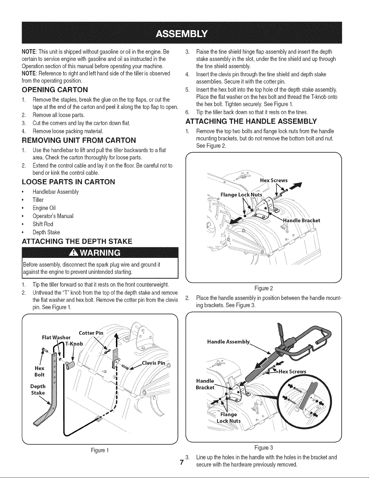
2. Unthreadthe "T" knobfromthe topof the depthstakeand remove
theflat washerand hexbolt. Removethecotter pinfromtheclevis
pin. See Figure1.
Cotter Pin
Fiat Washer
Hex
Bolt
Depth
Stake
Figure1
3. Raisethefine shieldhingeflapassemblyand insertthe depth
stakeassemblyin the slot, underthe fineshieldandup through
the tine shieldassembly.
4. Insertthe clevispinthroughthe fineshieldanddepthstake
assemblies.Secureit with the cotterpin.
5. Insertthe hex bolt intothe top holeof the depthstakeassembly.
Placethe flat washeron the hex boltandthreadthe T-knobonto
the hex bolt.Tightensecurely.SeeFigure1.
6. Tip the tiller backdownso thatit restson the tines.
ATTACHING THE HANDLE ASSEMBLY
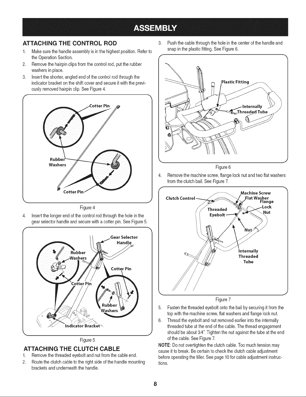
1. Removethe toptwo boltsand flangelock nutsfrom the handle
mountingbrackets,but do not removethe bottombolt andnut.
See Figure2.
f
.................. _,_i"_i_:...........
................... " Hex Screws
Flange LockNuts
Figure2
2. Placethe handleassemblyin positionbetweenthe handlemount-
ing brackets.See Figure3.
Handle Assembly.
Screws
7
J
Figure3
3. Lineup the holesinthe handlewiththe holesin the bracketand
securewiththe hardwarepreviouslyremoved.
ATTACHING THE CONTROL ROD
1. Makesurethe handleassemblyis in the highestposition.Referto
the OperationSection.
2. Removethehairpinclipsfromthe control rod,putthe rubber
washersin place.
3. Insertthe shorter,angledendof the controlrod throughthe
indicatorbracketonthe shiftcoverandsecureit with the previ-
ouslyremovedhairpinclip.See Figure4.
Rubb_
Washers
Figure4
4. Insertthe longerend of the control rodthroughthe hole in the
gearselectorhandleandsecurewitha cotterpin. SeeFigure5.
Gear Selector
Handle
Cotter Pin
Figure5
ATTACHING THE CLUTCH CABLE
1. Removethethreadedeyeboltand nut fromthe cableend.
2. Routethe clutchcableto the rightside of the handlemounting
bracketsandunderneaththe handle.
3. Pushthe cablethroughthe holein the centerof the handleand
snapin the plasticfitting. See Figure6.
Threaded Tube
Figure6
Removethe machinescrew,flangelocknut and two flat washers
fromthe clutchbail.See Figure7.
Machine Screw
Clutch Control Flat Washer
Range
Nut
internally
Threaded
Tu be
Figure7
5. Fastenthe threadedeyeboltontothe bail by securingit from the
top with the machinescrew,flatwashersand flangelocknut.
6. Threadtheeyeboltand nut removedearlierinto the internally
threadedtube atthe endof thecable.Thethreadengagement
shouldbeabout3/4".Tightenthe nutagainstthe tubeat the end
of the cable.SeeFigure7.
NOTE:Donot overtightentheclutchcable.Toomuchtensionmay
causeit to break.Becertainto checkthe clutchcableadjustment
beforeoperatingthe tiller.Seepage10for cableadjustmentinstruc-
tions.
8
SET-UP
Tire Pressure
Checkthe air pressureinbothtires.The air pressureshouldbe
between15-20PSI.Keepbothtiresequallyinflatedto helpprevent
machinefrompullingto one side.
Checking and Adding Oil
Theengine is shippedwithoutoil in theengine.Youmustfill the
enginewithoil beforeoperating.Runningthe enginewithinsufficient
_o can causeserous eng ne damageand vo d the productwarranty.
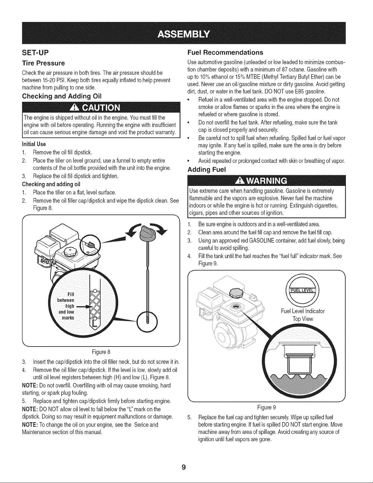
Initial Use
1. Removethe oil fill dipstick.
2. Placethetiller on levelground,usea funnelto emptyentire
contentsof the oil bottle providedwiththe unit intothe engine.
3. Replacethe oil fill dipstickandtighten.
Checkingand adding oil
1. Placethetiller ona flat, levelsurface.
2. Removethe oil fillercap/dipstickandwipethe dipstickclean.See
Figure8.
Figure8
3. Insertthe cap/dipstickintothe oil filler neck,butdo not screwitin.
4. Removethe oil fillercap/dipstick.If the levelislow,slowlyaddoil
untiloil levelregistersbetweenhigh(H) and low(L), Figure8.
NOTE: Donot overfill.Overfillingwithoil maycausesmoking,hard
starting,or sparkplugfouling.
5. Replaceandtightencap/dipstickfirmlybeforestartingengine.
NOTE: DONOTallowoil levelto fall belowthe"L"markon the
dipstick.Doingso mayresultinequipmentmalfunctionsordamage.
NOTE:Tochangethe oilon yourengine,see the Sericeand
Maintenancesectionof thismanual.
Fuel Recommendations
Useautomotivegasoline(unleadedor lowleadedto minimizecombus-
tion chamberdeposits)with a minimumof 87 octane.Gasolinewith
up to 10%ethanolor 15%MTBE(MethylTertiaryButylEther)can be
used.Neverusean oil/gasolinemixtureor dirty gasoline.Avoidgetting
dirt, dust,or waterinthe fuel tank.DO NOTuse E85gasoline.
* Refuelina well-ventilatedarea with the enginestopped.Do not
smokeor allowflamesor sparksin the areawherethe engineis
refueledor wheregasolineisstored.
. Donot overfillthe fueltank.After refueling,makesurethe tank
cap is closedproperlyandsecurely.
. Becarefulnotto spillfuel whenrefueling.Spilledfuel orfuel vapor
mayignite.If any fuelis spilled,makesurethe areaisdry before
startingthe engine.
. Avoidrepeatedor prolongedcontactwithskinor breathingof vapor.
Adding Fuel
Useextremecare whenhandlinggasoline.Gasolineisextremely
flammableandthevapors are explosive.Neverfuel the machine
indoorsorwhilethe engineishotor running.Extinguishcigarettes,
cigars,pipesandothersourcesof ignition.
1. Be sureengineis outdoorsandina well-ventilatedarea.
2. Cleanarea aroundthefuelfill capandremovethefuelfill cap.
3. UsinganapprovedredGASOLINEcontainer,addfuelslowly,being
carefulto avoidspilling.
4. Fillthe tank untilthe fuelreachesthe "fuelfull" indicatormark.See
Figure9.
FuelLevelIndicator
TopView
\\
.
Figure9
Replacethe fuelcapandtightensecurely.Wipeupspilledfuel
beforestartingengine.IffuelisspilledDO NOTstartengine.Move
machineawayfromareaof spillage.Avoidcreatinganysourceof
ignitionuntilfuelvaporsaregone.
9
ADJUSTMENTS
Priorto operatingyour tiller,carefullyread and followall instructions
below.Performall adjustmentsto verifyyourtiller is operatingsafely
andpropery.
Clutch Cable
NOTE:Servicethe enginewithoil andgasolinebeforecheckingthis
adjustment.Referto the separateEngineOperator'sManualpacked
withyourtillerfor properfuel andengineoil recommendations.
1. Positionthe tiller so thefront counterweightis againsta solid
object,suchas a wall.
2. With thegearselectionleverin NEUTRAL,start theengine.Refer
to the separateEngineOperator'sManual.
3. Standingon the right sideof the tiller,examinethe belt (insidethe
beltcover).It shouldnot be turning.
.
Donot putyourfingersunderthe belt cover.
f
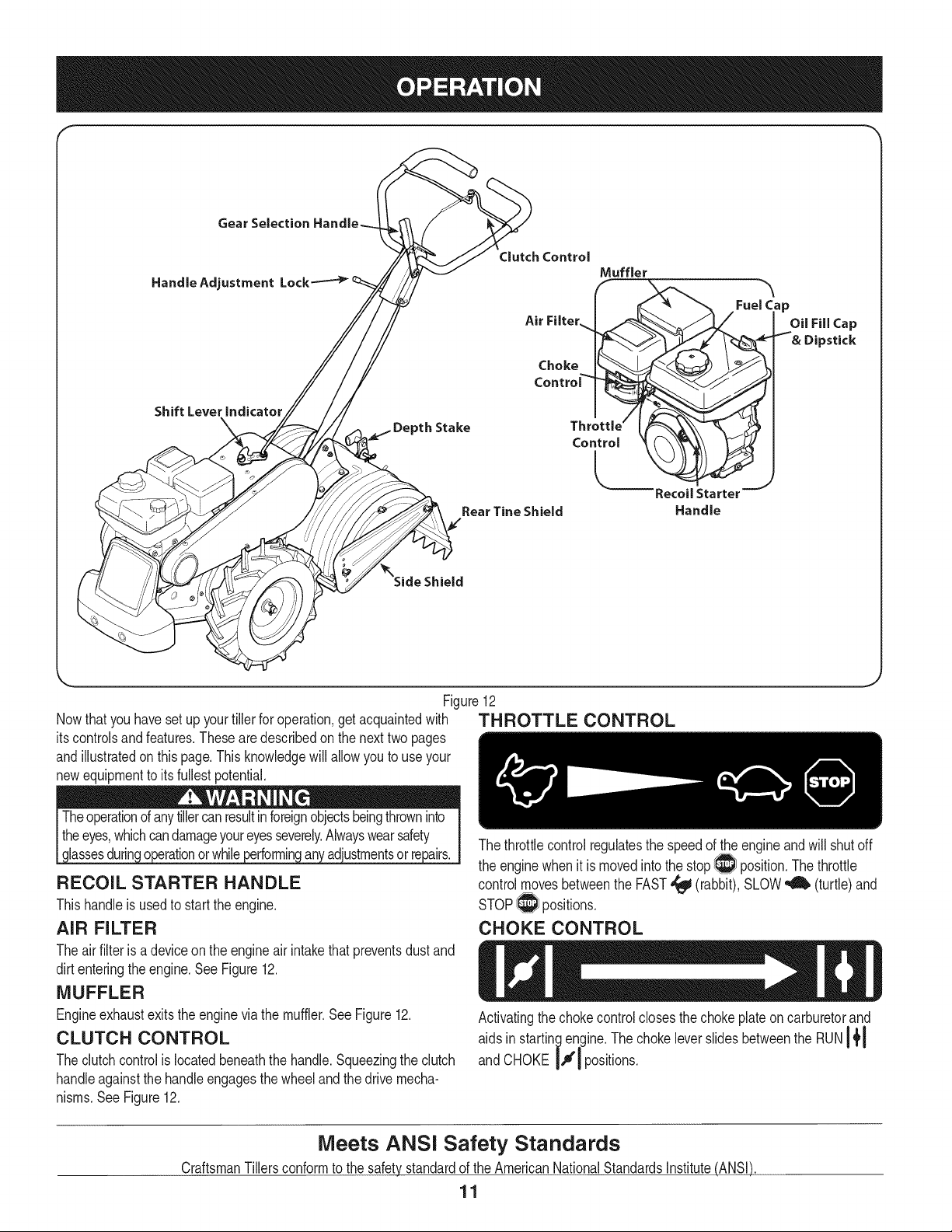
If the beltturnswithoutthe bail engaged,adjustit by un-threading
the internallythreadedtubeat the end of the cablea fewturns
clockwise-- when standingin theoperator'sposition-- andthen
retightenthe nut againstthetube.SeeFigure10.
Internally
ThreadedTube
Handle
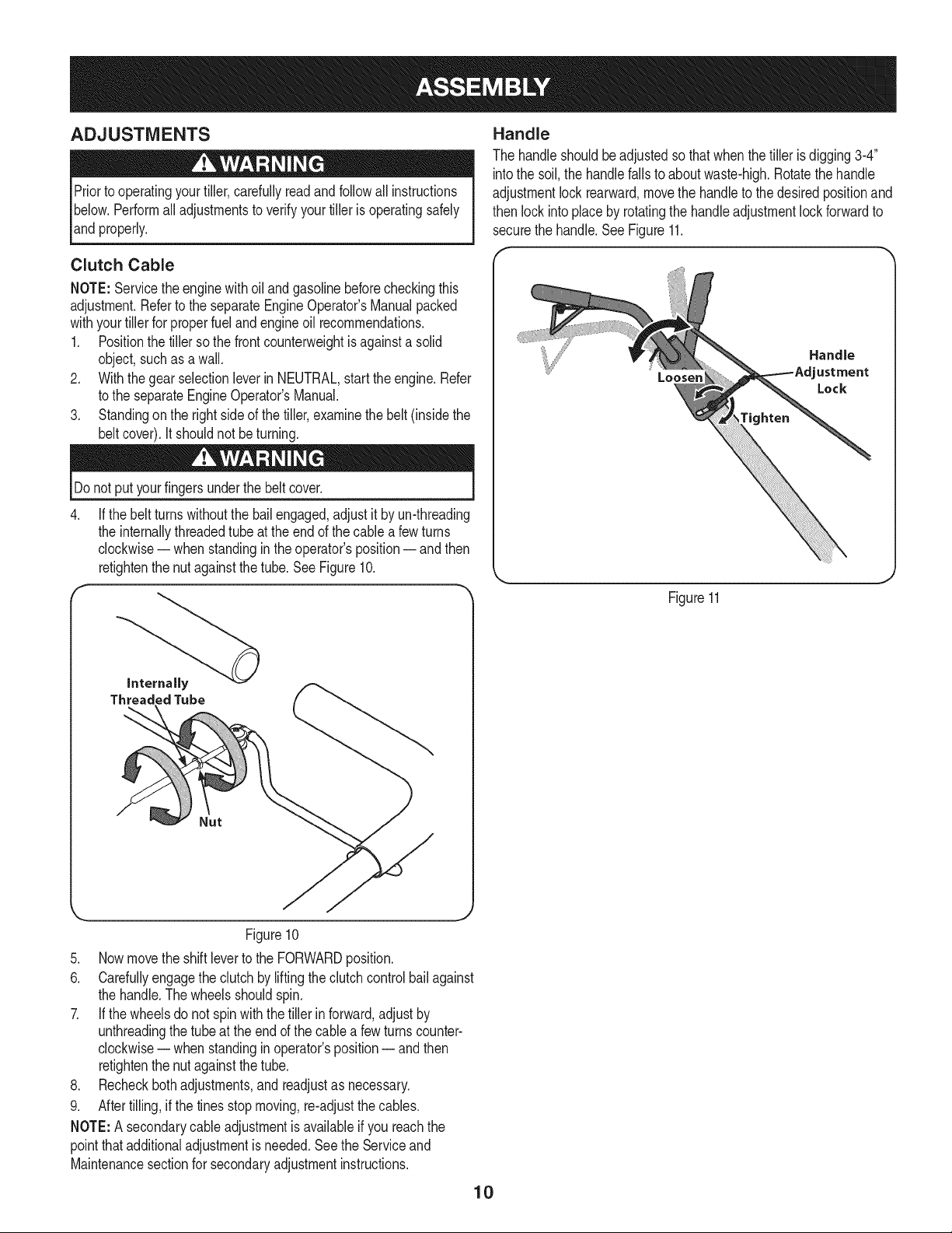
The handleshouldbeadjustedso thatwhenthe tiller is digging3-4"
intothe soil,the handlefallsto aboutwaste-high.Rotatethe handle
adjustmentlock rearward,movethe handleto thedesiredpositionand
then lock intoplace by rotatingthe handleadjustmentlockforwardto
securethe handle.See Figure11.
Loosen
tighten
Handle
ustment
Lock
Figure11
Figure10
5. Now movethe shiftleverto the FORWARDposition.
6. Carefullyengagethe clutchby lifting theclutchcontrol bail against
the handle.Thewheelsshouldspin.
7. If thewheelsdo not spinwiththe tiller inforward,adjustby
unthreadingthe tube at the endof the cablea fewturns counter-
clockwise-- when standingin operator'sposition-- andthen
retightenthe nut againstthetube.
8. Recheckbothadjustments,andreadjustas necessary.
9. After tilling,if the tines stop moving,re-adjustthe cables.
NOTE:A secondarycableadjustmentis availableif you reachthe
pointthat additionaladjustmentis needed.Seethe Serviceand
Maintenancesectionfor secondaryadjustmentinstructions.
10
Gear Selection
Handle Adjustment
Shift Lever indicator
_th Stake
Clutch Control
Air Filter..
Choke
Contro_
Throttlej
Control
l
Rear Tine Shield
Fuel _p
OUFillCap
Recoil Starter
Handle
Shield
Figure12
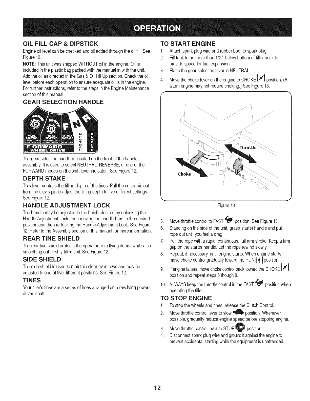
Nowthat youhavesetup yourtillerfor operation,get acquaintedwith TH BOTTLE CONTROL
itscontrolsand features.Thesearedescribedon the nexttwopages
andillustratedon thispage.This knowledgewill allowyou to useyour
newequipmentto itsfullestpotential.
Theoperationof anytillercanresultinforeignobjectsbeingthrowninto
theeyes,whichcandamageyoureyesseverely.Alwayswearsafety
assesdur n o eraton or wh e erformn an adustmentsor re a rs.
RECOIL STARTER HANDLE
Thishandleisusedto startthe engine.
AiR FILTER
The throttlecontrolregulatesthe speedof the engineandwill shutoff
the enginewhenit ismovedintothe stop_ position.Thethrottle
controlmovesbetweenthe FAST,_ (rabbit),SLOW_ (turtle) and
STOP_ positions.
CHOKE CONTROL
Theair filter isadeviceonthe engineair intakethat preventsdustand
dirt enteringthe engine.SeeFigure12.
MUFFLER
Engineexhaustexitsthe enginevia the muffler.SeeFigure12.
CLUTCH CONTROL
Theclutchcontrolislocatedbeneaththe handle.Squeezingthe clutch
handleagainstthe handleengagesthewheeland thedrive mecha-
nisms.SeeFigure12.
Activatingthe chokecontrolclosesthe chokeplateon carburetorand
aids in startingengine.The chokeleverslidesbetweenthe RUNI{I
and CHOKEIJl positions.
Meets ANSi Safety Standards
CraftsmanTillersconformto the safetystandardof the AmericanNationalStandardsInstitute(ANSI)
11
OiL FiLL CAP & DIPSTICK
Engineoil levelcan be checkedand oiladdedthroughtheoil fill. See
Figure12.
NOTE:This unitwasshippedWITHOUToil inthe engine.Oil is
includedinthe plasticbag packedwiththe manualin with the unit.
Addtheoil as directedintheGas & OilFill Up section.Checkthe oil
levelbeforeeachoperationto ensureadequateoil is inthe engine.
Forfurther instructions,referto the stepsinthe EngineMaintenance
sectionof thismanual.
GEAR SELECTION HANDLE
Thegear selectionhandle islocatedonthe frontof thehandle
assembly.It is usedto select NEUTRAL,REVERSE,oroneof the
FORWARDmodeson the shiftleverindicator. SeeFigure12.
DEPTH STAKE
Thislevercontrolsthe tillingdepthof the tines.Pull thecotter pin out
fromtheclevis pinto adjustthe tillingdepthto five differentsettings.
SeeFigure12.
HANDLE ADJUSTMENT LOCK
Thehandle maybe adjustedto the heightdesiredby unlockingthe
HandleAdjustmentLock,then movingthe handlebars to thedesired
positionandthen re-lockingthe HandleAdjustmentLock.See Figure
12.Referto the Assemblysectionof this manualfor moreinformation.
REAR TiME SHIELD
The reartine shieldprotectsthe operatorfrom flyingdebriswhilealso
smoothingout freshlytilledsoil.SeeFigure12.
SIDE SHIELD
Theside shieldis usedto maintainclearevenrowsandmaybe
adjustedto oneof fivedifferentpositions.SeeFigure12.
TINES
Yourtiller'stinesarea seriesof hoesarrangedona revolvingpower-
drivenshaft.
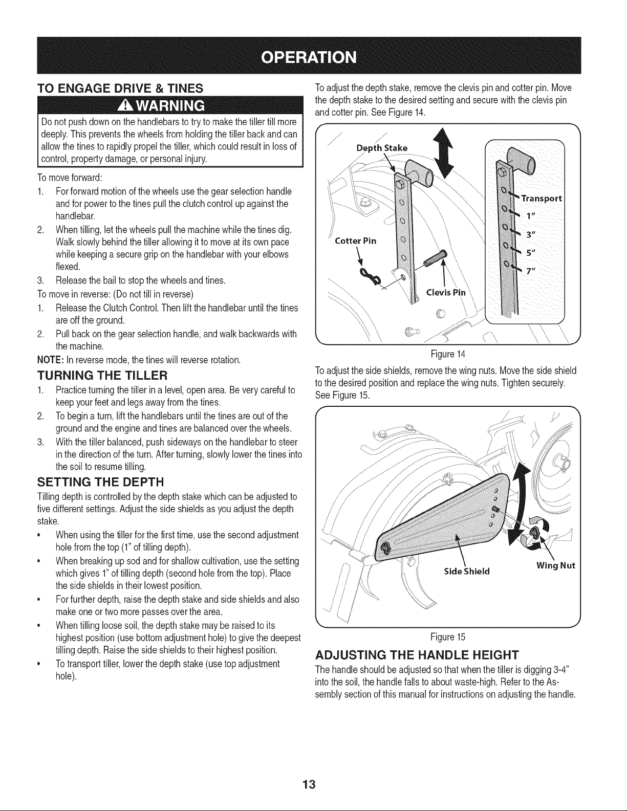
TO START ENGINE
1. Attachspark plug wireandrubberboot to sparkplug.
2. Filltank to no morethan 1/2" belowbottomof fillerneckto
providespacefor fuelexpansion.
3. Placethe gearselectionleverin NEUTRAL.
4. Movethe chokeleveron the engineto CHOKEI."1position(A
warmenginemaynotrequirechoking.)See Figure13.
Choke
Figure13
5. Movethrottlecontrolto FAST_ position.SeeFigure13.
6. Standingon the sideof the unit,graspstarterhandleandpull
ropeout untilyou feela drag.
7. Pullthe ropewith a rapid,continuous,full arm stroke.Keepafirm
gripon the starterhandle.Letthe roperewindslowly.
8. Repeat,if necessary,untilenginestarts.Whenenginestarts,
movechokecontrolgraduallytowardthe RUNI _'I position..
9. Ifenginefalters,movechokecontrolbacktowardthe CHOKEIJl
positionand repeatsteps5 though8.
10. ALWAYSkeepthe throttlecontrolin the FAST_ positionwhen
operatingthe tiller.
TO STOP ENGINE
1. To stopthe wheelsandtines, releasetheClutchControl.
2. Movethrottlecontrolleverto slow_ position.Whenever
possible,graduallyreduceenginespeedbeforestoppingengine.
3. Movethrottlecontrolleverto STOP position.
4. Disconnectspark plugwireandgroundit againsttheengineto
preventaccidentalstartingwhilethe equipmentis unattended.
12
TO ENGAGE DRIVE & TINES
Do not pushdownon the handlebarsto try to makethe tillertill more
deeply.This preventsthe wheelsfrom holdingthetiller backand can
allowthe tinesto rapidlypropelthetiller,whichcould resultin lossof
control,propertydamage,orpersonalinjury.
To moveforward:
1. Forforward motionof thewheels usethe gear selectionhandle
andfor powertothe tinespullthe clutchcontrolupagainstthe
handlebar.
2. Whentilling,letthe wheelspullthe machinewhile thetinesdig.
Walkslowlybehindthe tillerallowingit to moveat its ownpace
whilekeepinga securegrip on the handlebarwithyourelbows
flexed.
3. Releasethe bailto stopthe wheelsand tines.
To movein reverse:(Do not till in reverse)
1. Releasethe ClutchControl.Then liftthe handlebaruntilthe tines
areoff the ground.
2. Pull back on the gearselectionhandle,andwalkbackwardswith
the machine.
NOTE: In reversemode,the tineswill reverserotation.
TURNING THE TILLER
1. Practiceturningthetiller in a level,open area.Beverycarefulto
keepyourfeetandlegs awayfromthe tines.
2. To begina turn,liftthe handlebarsuntilthe tinesareout of the
groundandthe engineand tines are balancedoverthe wheels.
3. With the tillerbalanced,pushsidewayson the handlebarto steer
in the directionof the turn.Afterturning,slowlylowerthe tinesinto
the soil to resumetilling.
SETTING THE DEPTH
Tillingdepthis controlledbythe depthstakewhichcan be adjustedto
fivedifferentsettings.Adjustthe sideshieldsas you adjustthe depth
stake.
• Whenusingthe tillerfor the firsttime, usethe secondadjustment
holefromthetop (1"of tillingdepth).
• Whenbreakingup sodand for shallowcultivation,usethe setting
whichgives1"of tillingdepth (secondholefromthe top). Place
the sideshieldsintheir lowestposition.
• Forfurtherdepth,raisethe depthstakeand side shieldsandalso
makeoneor twomorepassesoverthearea.
• Whentillingloosesoil,the depthstakemay be raisedto its
highestposition(use bottomadjustmenthole)to givethe deepest
tillingdepth. Raisethe sideshieldsto their highestposition.
• Totransporttiller,lowerthedepth stake(use topadjustment
hole).
Toadjust thedepth stake,removethe clevispinandcotterpin. Move
the depthstaketo the desiredsettingandsecurewiththe clevispin
andcotter pin.SeeFigure14.
j_
Depth Stake
Figure14
Toadjust the sideshields,removethe wingnuts. Movethe side shield
to the desiredpositionand replacethe wingnuts.Tightensecurely.
See Figure15.
f J
Side Shield Wing Nut
/
!
_h J
Figure15
ADJUSTING THE HANDLE HEIGHT
The handleshouldbeadjustedsothat whenthe tiller is digging3-4"
into the soil,thehandlefalls to aboutwaste-high.Referto the As-
semblysectionof this manualfor instructionson adjustingthe handle.
13
CLEARING THE TINES
Beforeclearingthetinesby hand,stoptheengine,allowall moving
partsto stop and disconnectthe sparkplug wire. Failureto followthis
warningcouldresult in personalinjury.
• Thetines havea self-clearingaction whicheliminatesmostof the
tanglingof debris. However,occasionallydry grass,stringystalks
ortough vinesmay becometangled.Followtheseproceduresto
helpavoidtanglingand to clearthe tines, ifnecessary.
• To reducetangling,setthedepth regulatordeep enoughto get
maximum"chopping"actionas the tineschopthe materialagainst
the ground.Also, try to till undercrop residuesor covercrops
whilethey are green,moistand tender.
• Whiletilling,try swayingthe handlebarsfromsideto side(about
6" to 12").This"fishtailing"action oftenclears the tinesof debris.
TILLING TiPS & TECHNIQUES
Beforetilling,contactyourtelephoneor utilitiescompanyandinquire
l ifundergroundequipmentor linesare usedon yourproperty.Do not
[till nearburiedelectriccables,telephonelines, pipesor hoses.
Tilling Depth
• This isa DDT(dual-directiontine)tiller.Asthewheelspullforward,
thetines rotatebackward.As thewheelspullrearward,the tines
rotateforward.Thiscreatesan "uppercut"fineactionwhichdigs
deeply,uprootingsoilandweeds.Don'toverloadtheengine,butdig
as deeplyas possibleoneachpass On laterpasses,thewheels
maytendto spinin the softdirt. Helpthem alongbyliftingup
slightlyonthehandlebar(onehand,palmup,worksmosteasily).
• Avoidthetemptationto pushdown on the handlebarsin an
attemptto force thetiller to digdeeper.Doingso takesthe weight
off the poweredwheels,causingthemto losetraction.Without
the wheelsto holdthe tillerback,the tineswill attemptto propel
towardsthe operatoror awayfrom the operator.
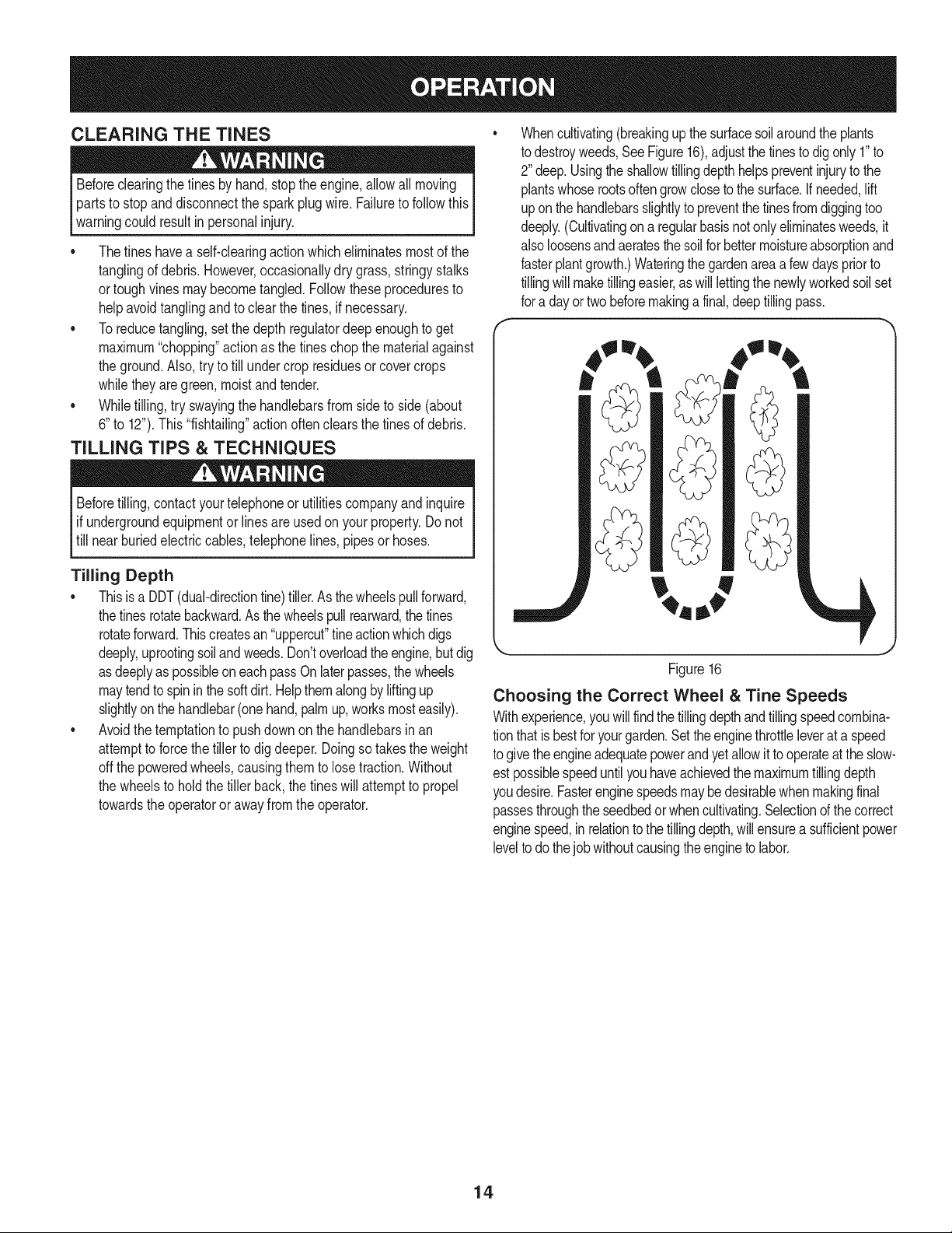
Whencultivating(breakingupthesurfacesoilaroundthe plants
todestroyweeds,SeeFigure16),adjustthe tinesto digonly1"to
2"deep.Usingthe shallowtillingdepthhelpspreventinjuryto the
plantswhoserootsoftengrowclosetothe surface.Ifneeded,lift
uponthe handlebarsslightlyto preventthetinesfromdiggingtoo
deeply.(Cultivatingon a regularbasisnotonlyeliminatesweeds,it
alsoloosensand aeratesthesoil forbettermoistureabsorptionand
fasterplantgrowth.)Wateringthegardenareaa few dayspriorto
tillingwillmaketillingeasier,as willlettingthenewlyworkedsoilset
fora dayortwobeforemakingafinal,deep tillingpass.
,j
Figure16
Choosing the Correct Wheel & Tine Speeds
Withexperience,you willfindthetillingdepthandtillingspeedcombina-
tionthat isbestfor yourgarden.Setthe enginethrottleleverat a speed
togivetheengineadequatepowerandyetallowit tooperateatthe slow-
estpossiblespeeduntilyou haveachievedthe maximumtillingdepth
youdesire.Fasterenginespeedsmaybedesirablewhenmakingfinal
passesthroughtheseedbedor whencultivating.Selectionofthe correct
enginespeed,inrelationto thetillingdepth,willensurea sufficientpower
levelto do thejobwithoutcausingtheengineto labor.
14
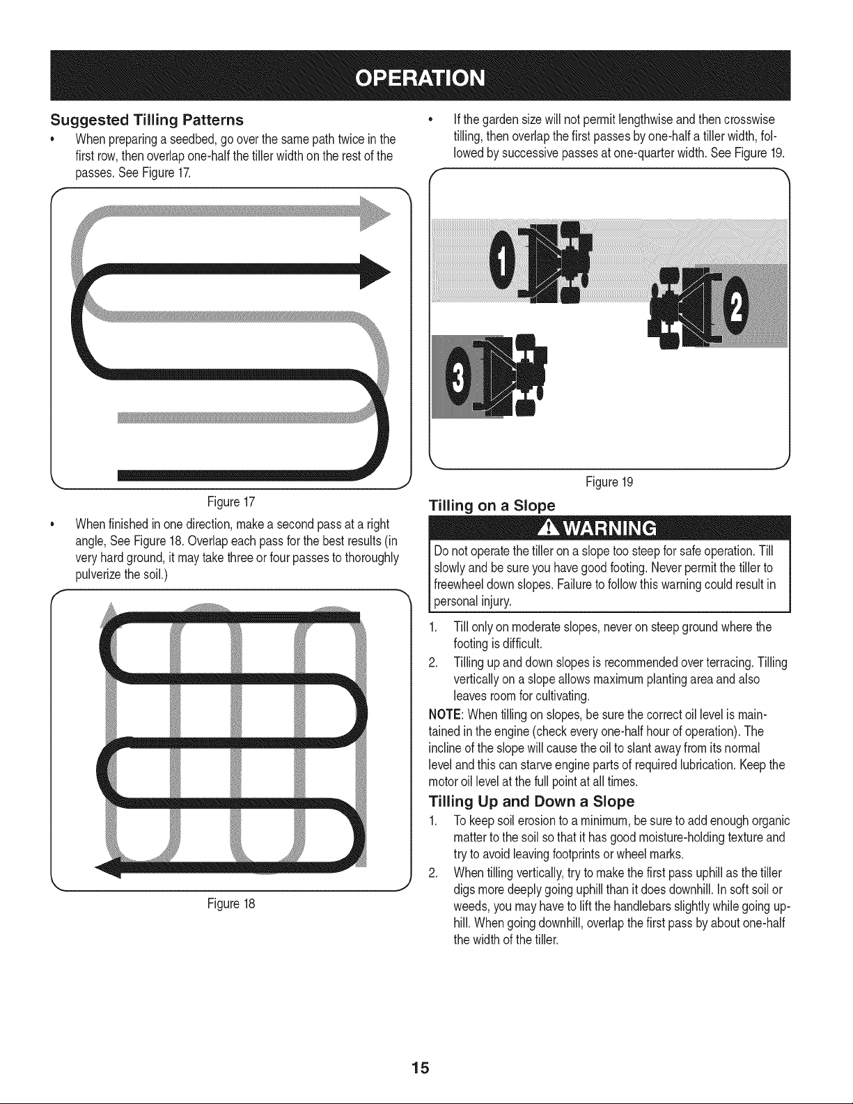
Suggested Tilling Patterns
• Whenpreparinga seedbed,gooverthe samepathtwice in the
first row,thenoverlapone-halfthetiller width on the restof the
passes.SeeFigure17.
• If the gardensizewill notpermitlengthwiseand thencrosswise
tilling,thenoverlapthe first passesby one-halfa tiller width,fol-
lowedby successivepassesat one-quarterwidth.See Figure19.
Figure17
Whenfinishedin one direction,makea second passat a right
angle,See Figure18.Overlapeachpassfor the bestresults(in
veryhardground,it maytakethreeor four passesto thoroughly
pulverizethe soil.)
J
== ==== ==d
Figure18
J
Figure19
Tilling on a Slope
Donotoperatethetiller on a slopetoo steepfor safeoperation.Till
slowlyand be sureyou havegoodfooting.Neverpermitthe tillerto
freewheeldownslopes.Failureto followthiswarningcould resultin
personalinjury.
1. Till onlyon moderateslopes,neveron steepgroundwherethe
footingisdifficult.
2. Tillingupand downslopesis recommendedoverterracing.Tilling
verticallyon aslopeallows maximumplantingareaandalso
leavesroomfor cultivating.
NOTE:Whentillingon slopes,be surethe correctoil levelismain-
tainedin theengine(checkeveryone-halfhourof operation).The
inclineof the slopewill causethe oil to slantawayfrom itsnormal
leveland this canstarveengineparts of requiredlubrication.Keepthe
motoroil levelat the full pointat all times.
Tilling Up and Down a Slope
1. To keepsoilerosionto a minimum,besureto addenoughorganic
matterto the soil sothat it has goodmoisture-holdingtextureand
try to avoidleavingfootprintsor wheelmarks.
2. Whentillingvertically,try to makethe first passuphillas thetiller
digs moredeeplygoinguphillthanit doesdownhill.Insoft soil or
weeds,youmayhaveto liftthe handlebarsslightlywhilegoingup-
hill. Whengoingdownhill,overlapthefirst passby aboutone-half
the width of the tiller.
15
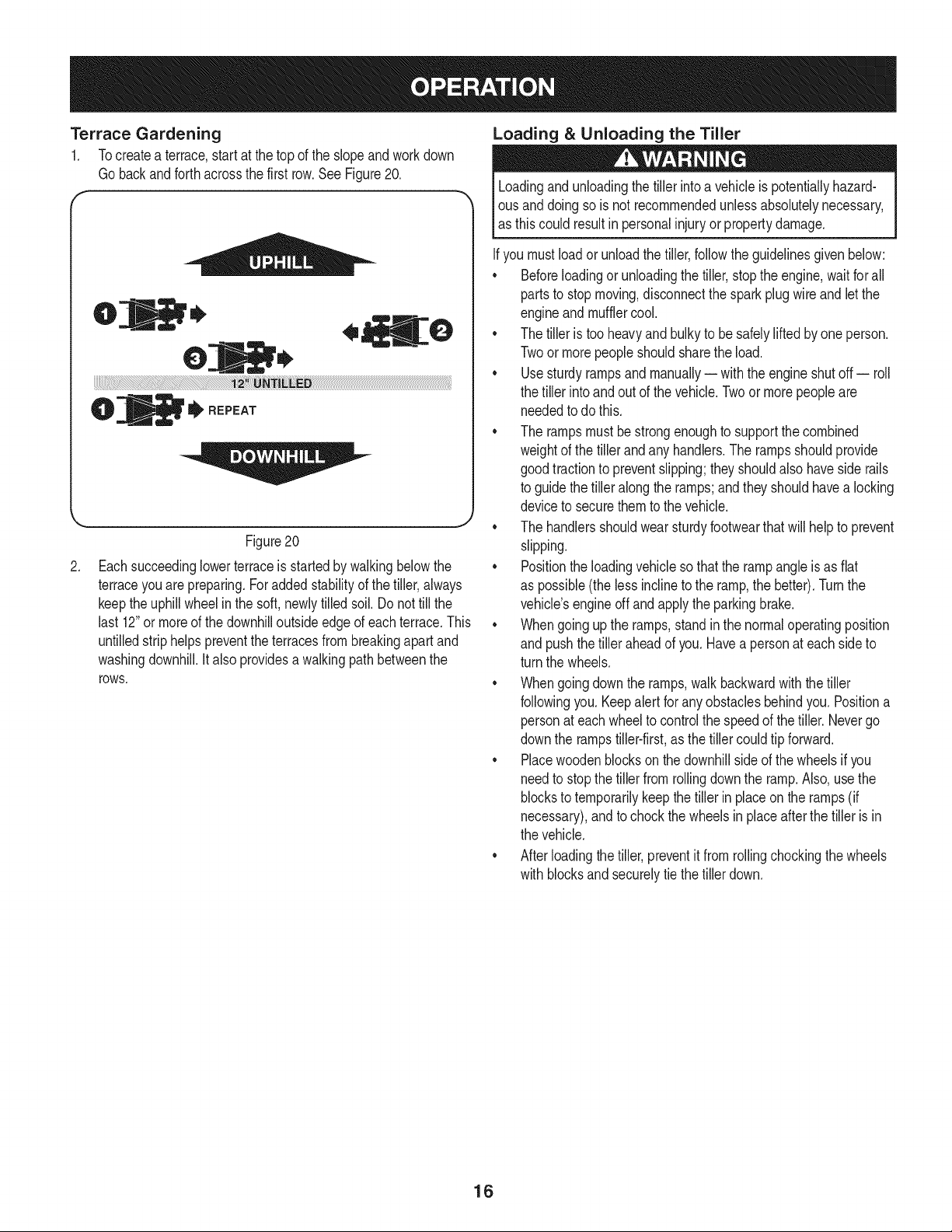
Terrace Gardening
1. Tocreatea terrace,start at thetop of the slopeandworkdown
Gobackandforthacrossthe first row.See Figure20.
f
to,
O
tI'REPEAT
.
J
Figure20
Eachsucceedinglowerterraceis startedby walkingbelowthe
terraceyouare preparing.Foraddedstabilityof thetiller,always
keepthe uphillwheelin the soft,newlytilled soil. Donot till the
last 12"or moreof thedownhilloutsideedgeof each terrace.This
untilledstriphelps preventtheterracesfrombreakingapart and
washingdownhill.Italso providesa walkingpathbetweenthe
rOWS.
Loading & Unloading the Tiller
Loadingandunloadingthe tillerintoa vehicleis potentiallyhazard-
I ous anddoingso is not recommendedunlessabsolutelynecessary,
las thiscould resultin personalinjuryorpropertydamage.
Ifyou mustloadorunloadthe tiller,followthe guidelinesgivenbelow:
• Beforeloadingor unloadingthe tiller, stopthe engine,waitfor all
partsto stopmoving,disconnectthe sparkplugwireand let the
engineand mufflercool.
• The tilleris tooheavyand bulkyto besafelylifted byone person.
Twoor morepeopleshouldsharethe load.
• Usesturdyrampsand manually-- with the engineshutoff-- roll
the tiller intoand out of the vehicle.Twoor morepeopleare
neededto do this.
• The rampsmustbe strongenoughto supportthe combined
weightof the tiller and anyhandlers.The rampsshouldprovide
goodtractionto preventslipping;theyshouldalsohaveside rails
to guide the tilleralong the ramps;andtheyshouldhavea locking
deviceto securethemto the vehicle.
• The handlersshouldwearsturdyfootwearthatwill help to prevent
slipping.
• Positionthe loadingvehicleso that the rampangleis as flat
as possible(the lessinclineto the ramp,the better).Turnthe
vehicle'sengineoff andapplythe parkingbrake.
• Whengoingupthe ramps,standin the normaloperatingposition
and pushthetiller aheadof you.Havea personat each sideto
turn the wheels.
• Whengoingdownthe ramps,walkbackwardwith the tiller
followingyou.Keepalertfor anyobstaclesbehindyou.Positiona
personat eachwheelto controlthe speedof the tiller.Nevergo
downthe rampstiller-first,as the tillercouldtip forward.
• Placewoodenblockson thedownhillsideof the wheelsif you
needto stop the tillerfrom rollingdownthe ramp.Also, usethe
blocksto temporarilykeepthe tiller in placeon the ramps(if
necessary),and to chockthe wheelsin placeafterthe tiller is in
the vehicle.
• After loadingthe tiller,preventit from rollingchockingthe wheels
with blocksandsecurelytie the tillerdown.
16
MAINTENANCE SCHEDULE
Beforeperforminganytypeof maintenance/service,disengageall
controlsandstoptheengine.Waituntilall movingpartshavecometo
acompletestop.Disconnectsparkplugwireandgrounditagainstthe
enginetopreventunintendedstarting.Alwayswearsafetyglassesduring
operationor whileperforminganyadjustmentsor repairs.
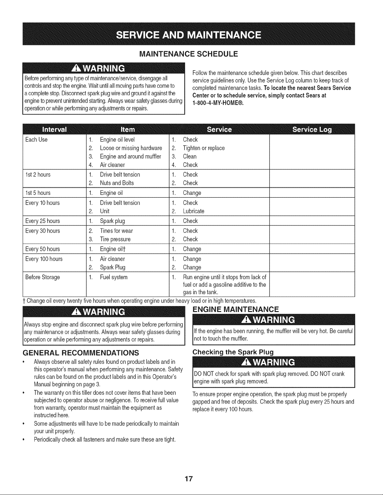
Followthe maintenanceschedulegivenbelow.This chart describes
serviceguidelinesonly. Usethe ServiceLogcolumnto keeptrackof
completedmaintenancetasks.To locate the nearest Sears Service
Centeror to scheduleservice,simplycontactSears at
1-800-4-MY-HOME®.
EachUse
1st2 hours
1st5 hours
Every10hours
Every25 hours
Every30 hours
Every50 hours
Every100hours
BeforeStorage
1. Engineoil level
2. Looseormissinghardware
3. Engineand aroundmuffler
4. Air cleaner
1. Drivebelt tension
2. Nutsand Bolts
1. Engineoil
1. Drivebelt tension
2. Unit
1. Sparkplug
2. Tinesfor wear
3. Tirepressure
1. Engineoi11-
1. Air cleaner
2. SparkPlug
1. Fuelsystem
= =
1. Check
2. Tightenor_place
3. Clean
4. Check
1. Check
2. Check
1. Change
1. Check
2. Lubricate
1. Check
1. Check
2. Check
1. Change
1. Change
2. Change
1. Runengineuntilit stopsfromlackof
fuel or add a gasolineadditiveto the
gas in thetank.
Changeoileverytwentyfivehourswhenoperatingengineunderheavyloadorin hightemperatures.
ENGINE MAINTENANCE
Alwaysstopengineanddisconnectsparkplug wirebeforeperforming
lany maintenanceor adjustments.Alwayswearsafetyglassesduring
_operationor while performingany adjustmentsor repairs.
GENERAL RECOMMENDATIONS
• Alwaysobserveall safety rulesfoundon productlabelsandin
thisoperator'smanualwhenperformingany maintenance.Safety
rulescan befoundon the productlabelsandin this Operator's
Manualbeginningon page3.
• Thewarrantyon thistillerdoes notcover itemsthathavebeen
subjectedto operatorabuseor negligence.Toreceivefull value
fromwarranty,operatormust maintainthe equipmentas
instructedhere.
• Someadjustmentswillhaveto be madeperiodicallyto maintain
yourunit properly.
• Periodicallycheckall fastenersand makesurethesearetight.
Ifthe enginehas beenrunning,the mufflerwill beveryhot. Becareful
notto touchthe muffler.
Checking the Spark Plug
DO NOTcheckfor sparkwith spark plug removed.DO NOTcrank
enginewithsparkplug removed.
Toensureproperengineoperation,the sparkplugmustbe properly
gappedandfree of deposits.Checkthe sparkplugevery25hoursand
replaceit every 100 hours.
17
.
.
.
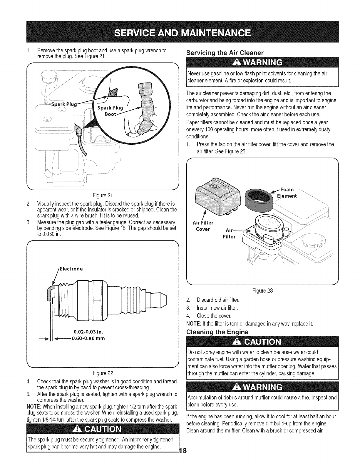
Removethespark plug bootanduse a sparkplug wrenchto
removethe plug.See Figure21.
Figure21
Visuallyinspectthe spark plug.Discardthe spark plug if thereis
apparentwear,orif the insulatoris crackedor chipped.Cleanthe
sparkplugwitha wirebrush if it is to be reused.
Measurethe pluggapwitha feelergauge.Correctas necessary
by bendingsideelectrode.SeeFigure18.The gapshouldbeset
to 0.030in.
Servicing the Air Cleaner
Neverusegasolineor lowflashpoint solventsfor cleaningtheair
cleanerelement.A fireor explosioncould result.
The air cleanerpreventsdamagingdirt, dust,etc.,fromenteringthe
carburetorandbeing forcedintothe engineand is importantto engine
lifeand performance.Neverrunthe enginewithoutanair cleaner
completelyassembled.Checkthe air cleanerbeforeeachuse.
Paperfilterscannotbecleanedand mustbe replacedoncea year
or every100operatinghours;moreoftenif usedinextremelydusty
conditions.
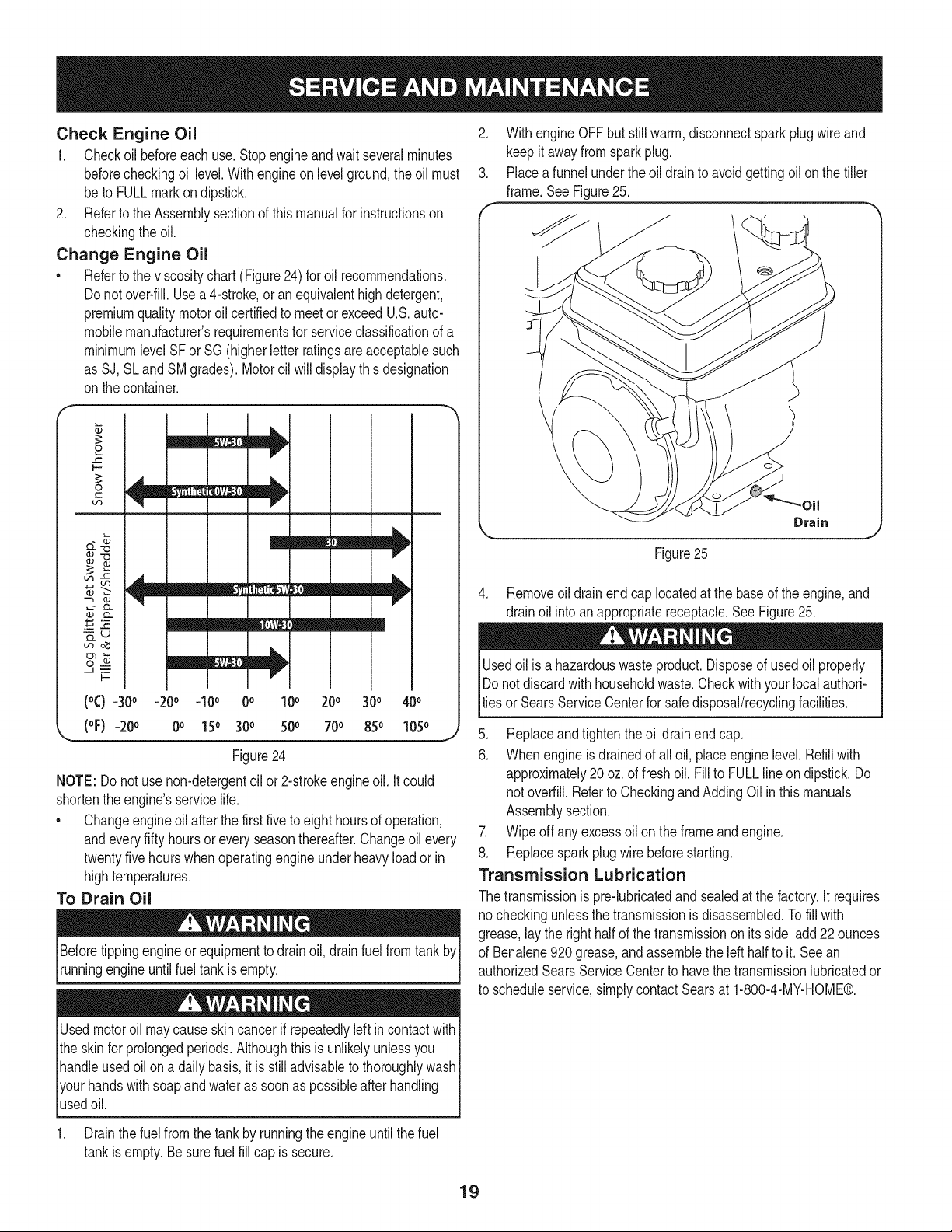
1. Pressthetab on the air filtercover,lift the coverand removethe
air filter.See Figure23.
..........
Air Filter
Cover
Filter
Figure22
4. Checkthatthe sparkplugwasheris in good conditionand thread
the sparkplug in by handto preventcross-threading.
5. After thesparkplugis seated,tightenwith a spark plugwrenchto
compressthe washer.
NOTE:Wheninstallinga newsparkplug,tighten1/2turnafterthe spark
plugseatstocompressthewasher.Whenreinstallinga usedsparkplug,
tighten1/8-1/4turnafterthesparkplugseatsto compressthewasher.
The sparkplug mustbe securelytightened.An improperlytightened
sparkplugcan becomevery hot andmaydamagethe engine.
Figure23
2. Discardoldair filter.
3. Installnewair filter.
4. Closethe cover.
NOTE:If the filteris tornor damagedinany way,replaceit.
Cleaning the Engine
Do notsprayenginewithwaterto cleanbecausewatercould
contaminatefuel.Usinga gardenhoseor pressurewashingequip-
mentcan alsoforcewaterintothe muffleropening.Waterthatpasses
throughthe mufflercan enterthe cylinder,causingdamage.
Accumulationof debrisaroundmufflercouldcausea fire. Inspectand
clean beforeevery use.
Ifthe enginehas beenrunning,allow it to coolfor at leasthalf an hour
beforecleaning.Periodicallyremovedirt build-upfromthe engine.
Cleanaroundthe muffler.Cleanwitha brushor compressedair.
Check Engine Oil
1. Checkoilbeforeeachuse.Stopengineandwaitseveralminutes
beforecheckingoillevel.Withengineonlevelground,theoilmust
betoFULLmarkondipstick.
2. RefertotheAssemblysectionofthismanualforinstructionson
checkingthe oil.
Change Engine Oil
• Referto the viscositychart (Figure24) for oil recommendations.
Do notover-fill.Usea4-stroke,oran equivalenthighdetergent,
premiumqualitymotoroil certifiedto meet or exceedU.S.auto-
mobilemanufacturer'srequirementsfor serviceclassificationof a
minimumlevelSFor SG(higherletterratingsareacceptablesuch
as SJ, SLand SMgrades). Motoroil will displaythis designation
onthe container.
o
F-
©
C
V
V
mm Iml
Lf_
_u
--J
t-
(°C) =30° -20o =I0o 0o 100 200 300 400
(oF)-20 o 0o 150 300 500 700 850 1050
J
Figure24
NOTE: Donot use non-detergentoil or2-strokeengineoil. Itcould
shortentheengine'sservicelife.
• Changeengineoil after thefirst five to eight hoursof operation,
andeveryfifty hoursor every seasonthereafter.Changeoil every
twentyfivehourswhenoperatingengineunderheavyloadorin
hightemperatures.
To Drain Oil
Beforetippingengineor equipmentto drainoil, drainfuel fromtank by
runningengineuntilfuel tankisempty.
Usedmotoroil maycauseskincancerifrepeatedlyleftincontactwith
the skin for prolongedperiods.Althoughthis isunlikelyunlessyou
handleusedoil on a daily basis,itis still advisableto thoroughlywash
yourhandswithsoapand wateras soonas possibleafter handling
usedoil.
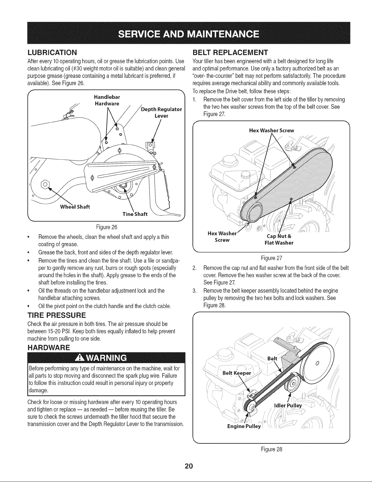
2. With engine OFFbut stillwarm,disconnectsparkplugwireand
keep itawayfromsparkplug.
3. Placea funnelunderthe oil drainto avoidgettingoil on the tiller
frame.See Figure25.
Drain
Figure25
4. Removeoil drainend cap locatedat the baseof the engine,and
drainoil intoan appropriatereceptacle.See Figure25.
Usedoil isa hazardouswasteproduct.Disposeof usedoil properly
IDo notdiscardwith householdwaste.Checkwithyour localauthori-
lties or SearsServiceCenterfor safedisposal/recyclingfacilities.
5. Replaceandtightenthe oildrainendcap.
6. Whenengineisdrainedof all oil, placeenginelevel. Refillwith
approximately20oz.of fresh oil. Fillto FULLline on dipstick.Do
not overfill.Referto CheckingandAddingOilinthismanuals
Assemblysection.
7. Wipeoff anyexcessoil on the frameandengine.
8. Replacesparkplugwire beforestarting.
Transmission Lubrication
The transmissionis pre-lubricatedand sealedat thefactory.It requires
no checkingunlessthe transmissionisdisassembled.Tofill with
grease,lay the righthalfof thetransmissionon itsside,add22ounces
of Benalene920grease,andassemblethe left half to it. See an
authorizedSearsServiceCenterto havethe transmissionlubricatedor
to scheduleservice,simplycontactSearsat 1-800-4-MY-HOME®.
1. Drainthe fuelfromthe tank by runningthe engineuntil thefuel
tankis empty.Be surefuel fill cap is secure.
19
LUBRiCATiON
Afterevery10operatinghours,oilor greasethe lubricationpoints.Use
cleanlubricatingoil (#30weightmotoroil is suitable)and cleangeneral
purposegrease(greasecontaininga metallubricantis preferred,if
available).SeeFigure26.
_'_ Handlebar
Hardware
Regulator
Figure26
• Removethewheels,clean thewheelshaft andapplya thin
coatingof grease.
• Greasethe back,front and sidesof the depth regulatorlever.
• Removethetinesandcleanthe fine shaft. Usea file or sandpa-
perto gently removeany rust,burrsor roughspots(especially
aroundthe holesinthe shaft). Applygreaseto the endsof the
shaftbeforeinstallingthe tines.
• Oil the threadsonthe handlebaradjustmentlockand the
handlebarattachingscrews.
• Oil the pivotpointon the clutchhandleand the clutchcable.
TiRE PRESSURE
Checktheair pressurein bothtires.The airpressureshouldbe
between15-20PSI.Keepbothtiresequallyinflatedto helpprevent
machinefrompullingto one side.
HARDWARE
Beforeperformingany typeof maintenanceonthe machine,wait for
all partsto stopmovinganddisconnectthe spark plugwire. Failure
to followthis instructioncouldresult inpersonalinjuryor property
damage.
Checkfor looseor missinghardwareafterevery10operatinghours
andtightenor replace-- as needed-- beforereusingthe tiller.Be
sureto checkthe screwsunderneaththe tillerhood that securethe
transmissioncoverand the DepthRegulatorLeverto thetransmission.
BELT REPLACEMENT
Yourtiller hasbeenengineeredwith a beltdesignedfor long life
andoptimalperformance.Useonly a factoryauthorizedbeltas an
"over-the-counter"belt maynot performsatisfactorily.The procedure
requiresaveragemechanicalabilityandcommonlyavailabletools.
To replacethe Drivebelt,followthesesteps:
1. Removethe beltcoverfromthe left sideof the tiller by removing
the two hexwasherscrewsfromthe topof the beltcover.See
Figure27.
Hex Washer Screw
He× Washel
Cap Nut &
Screw Flat Washer
Figure27
Removethe cap nutandflatwasherfromthe front sideof the belt
cover.Removethe hexwasherscrewat the backof the cover.
SeeFigure27.
Removethe belt keeperassemblylocatedbehindthe engine
pulleyby removingthe two hex boltsand lockwashers.See
Figure28.
...............................
/ 7\
...........!..... Idler Pulley
Figure28
2O
4. Removethe idlerpulleyby removingthe boltand nut.
SeeFigure27.
5. Removethe old beltandinstallthe newbelt.Followthe instruc-
tionsin reverseorderto re-installthe belt keeperand belt cover.
SeeFigure27.
NOTE: Uponreassernbly,makecertainthe belt is routedoverthe idler
pulleyand insideof the beltkeepersbythe engine pulley.
TINES
Thetineswillwearwithuseandshouldbeinspectedat thebeginningof
eachtillingseasonandafterevery30operatinghours.Thetinescan be
replaced.Referto thePartsList sectionof this manualforpartnumbers.
Tine Inspection
Withuse,the tines will becomeshorter,narrowerand pointed.Badly
worntines will resultina lossof tillingdepth,and reducedeffective-
nesswhen choppingup and turningunderorganicmatter.
Removing/Installing a Tine Assembly
1. Removethe tine shieldend coversand sideshieldsby removing
thethree wingnuts on each sidethat securethem.
2. A fine assemblyconsistsof a left hand fineanda righthandfine.
NOTE:Thefine assemblymovesin a counter-rotatingmotionwith
the sharpedgesof thetinespositionedto enterthe soil firstwhen
counter-rotating.Notethis positionof thetines for reinstallationof the
newfine assemblies.
3. To removeafine assembly,simplyremovethe internalcotter pin
securingthe clevispin. SeeFigure29.
• ® Clevis Pin
/
_ J
Figure29
4. Removethe clevispin andslidethe assemblyto the outsideof
the unitandoff of the fine shaft.
5. Beforereinstallingthe fineassembly,inspectthe tine shaftfor
rust, roughspotsorburrs.Lightlyfile or sand,as needed.Applya
thincoat of greaseto the shaft.
6. Installeachfine assemblyso thatthe cutting(sharp)edgeof the
tineswillenterthesoilfirstwhenthetillermovesforward.Keepin
mindthatthesetinesarecounter-rotating,so securethetine as-
semblytothe tineshaftusingthe clevispinandinternalcotterpin.
ADJUSTMENTS
Handle
The handlemay be adjustedto thedesiredheight.Referto the
Assemblysectionfor details.
Secondary Clutch Cable Adjustment
Ifadditionaladjustmentis necessaryafterthe primaryadjustmentfrom
the Assemblysectioncan nolongerbe used,the secondaryadjust-
mentcan be performedas follows:
1. Removethe beltcoveras instructedthe Belt Replacementon
page21.
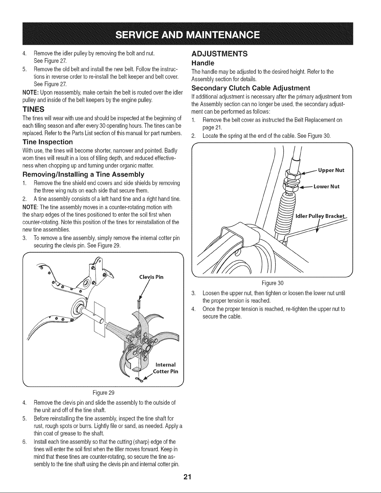
2. Locatethe springat the end of the cable.See Figure30.
.
4.
Figure30
Loosenthe uppernut,thentightenor loosenthe lowernut until
the propertensionis reached.
Once thepropertensionis reached,re-tightenthe uppernutto
securethe cable.
21
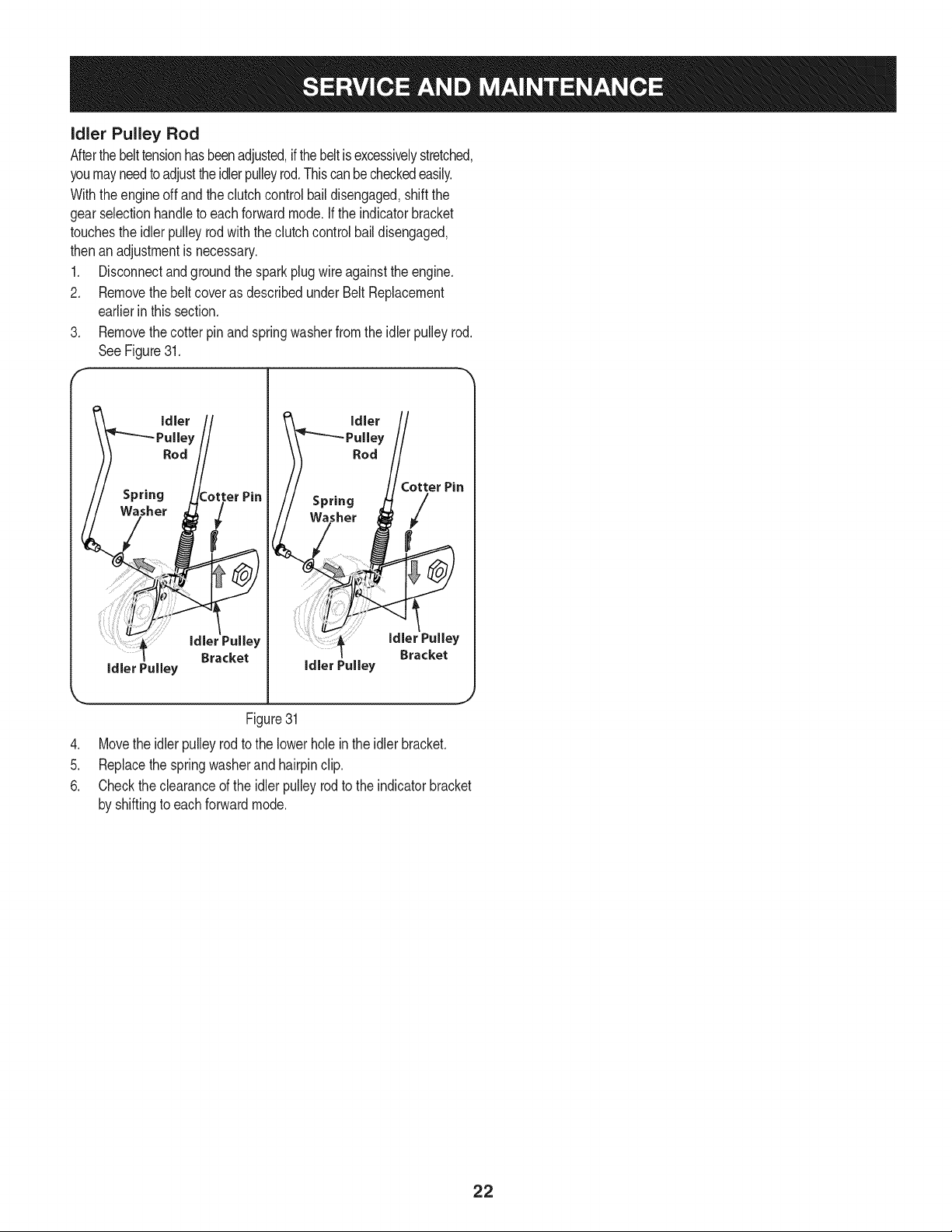
idler Pulley Rod
Afterthe belttensionhasbeenadjusted,ifthebeltis excessivelystretched,
youmayneedtoadjustthe idlerpulleyrod.Thiscanbe checkedeasily.
Withtheengineoff and the clutchcontrolbail disengaged,shiftthe
gearselectionhandleto eachforwardmode.Ifthe indicatorbracket
touchesthe idlerpulleyrod with theclutchcontrol bail disengaged,
thenan adjustmentis necessary.
1. Disconnectand groundthe sparkplugwire againsttheengine.
2. Removethebelt coveras describedunderBelt Replacement
earlierinthissection.
3. Removethecotterpin and springwasherfrom the idlerpulleyrod.
SeeFigure31.
F
idler Pulley
Pin
idler Pulley
Figure31
4. Movethe idlerpulleyrodto the lowerhole inthe idlerbracket.
5. Replacethespringwasherand hairpinclip.
6. Checktheclearanceof the idlerpulleyrodto the indicatorbracket
by shiftingto each forwardmode.
22
Neverstoretiller withfuel in tankindoorsor in poorlyventilatedareasI
wherefuel fumesmay reachan open flame,spark,or pilotlightas on
a furnace,waterheater,c othesdryer,orgas app ance. 1
PREPARING THE ENGINE
Enginesstored between30and 90daysneedto betreatedwitha
gasolinestabilizerandenginesstoredover90daysneedto bedrained
of fuel to preventdeteriorationandgumfromforminginfuel systemor
on essentialcarburetorparts.Ifthe gasolineinyourenginedeterio-
ratesduringstorage,you mayneedto havethecarburetor,andother
fuel systemcomponents,servicedor replaced.
1. Removeallfuel from tank by runningengineuntilit stopsfrom
lackof fuel.
Neverleaveengineunattendedwhileit is running.
2. Changethe oil. See ChangeEngineOil in SERVICEAND
MAINTENANCEsection.
3. Removespark plugand pourabouta 1/2ounceof engineoilinto
the cylinder.Replacesparkplugandcrankit slowlyto distribute
oil.
4. Cleandebrisfrom aroundtheengineandthe muffler.Touchup
any damagedpaint,andcoat otherareasthatmay rustwith a light
filmof oil.
5. Storein a clean,dry and wellventilatedareaawayfromany ap-
pliancethat operateswitha flameorpilot light, suchas a furnace,
waterheater,orclothesdryer.Alsoavoidany areawith a spark
producingelectricmotor,or wherepowertoolsare operated.
6. Ifpossible,also avoidstorageareaswithhighhumidity,because
that promotesrust and corrosion.
7. Keeptheenginelevelinstorage.Tiltingcan causefuel or oil
leakage.
PREPARING THE TILLER
Whenthe tillerwon't be usedfor an extendedperiod,prepareit for
storageas follows:
1. Cleanthe tillerand engine.
2. Followthe lubricationrecommendationsandcheckfor looseparts
and hardware.
3. Storethe tiller ina clean,dry area.
4. Neverstorethe tillerwith fuel inthe fuel tankinan enclosedarea
wheregas fumescould reachan openflameor spark,or where
ignitionsourcesare present(spaceheaters,hot waterheaters,
furnaces,etc.).
23
Beforeperforminganytyped maintenance/service,disengageall controlsand stoptheengine.Waituntilall
movingpartshavecometo acompletestop.Disconnectsparkplugwireandgroundit againsttheenginetoprevent
unintendedstarting.Alwayswearsafetyglassesduringoperationorwhileperforminganyadjustmentsorrepairs.
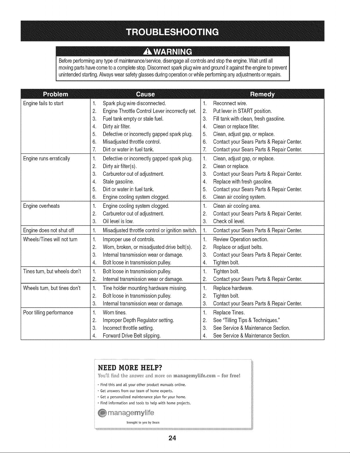
Enginefailsto start
Enginerunserratically
Engineoverheats
Enginedoesnot shut off
Wheels/Tineswill notturn
Tinesturn, butwheelsdon't
Wheelsturn,buttines don't
Poortilling performance
1. Sparkplugwire disconnected.
2. EngineThrottleControlLeverincorrectlyset.
3. Fueltankemptyor stalefuel.
4. Dirtyair filter.
5. Defectiveor incorrectlygappedsparkplug.
6. Misadjustedthrottlecontrol.
7. Dirt or water in fuel tank.
1. Defectiveor incorrectlygappedsparkplug.
2. Dirtyairfilter(s).
3. Carburetorout of adjustment.
4. Stalegasoline.
5. Dirt or water in fuel tank.
6. Enginecoolingsystemclogged.
1. Enginecoolingsystemclogged.
2. Carburetorout of adjustment.
3. Oil levelis low.
1. Misadjustedthrottlecontrolor ignitionswitch.
1. Improperuse of controls.
2. Worn,broken,or misadjusteddrive belt(s).
3. Internaltransmissionwearor damage.
4. Bolt looseintransmissionpulley.
1. Bolt loosein transmissionpulley.
2. Internaltransmissionwearor damage.
1. Tine holdermountinghardwaremissing.
2. Bolt loosein transmissionpulley.
3. Internaltransmissionwearor damage.
1. Worntines.
2. ImproperDepthRegulatorsetting.
3. Incorrectthrottlesetting.
4. ForwardDriveBeltslipping.
1. Reconnectwire.
2. Putleverin STARTposition.
3. Filltank with clean,fresh gasoline.
4. Cleanor replacefilter.
5. Clean, adjustgap,or replace.
6. Contactyour SearsParts& RepairCenter.
7. Contactyour SearsParts& RepairCenter.
1. Clean,adjustgap,or replace.
2. Cleanor replace.
3. Contactyour SearsParts& RepairCenter.
4. Replacewithfresh gasoline.
5. Contactyour SearsParts& RepairCenter.
6. Cleanair coolingsystem.
1. Cleanair coolingarea.
2. Contactyour SearsParts& RepairCenter.
3. Checkoil level.
1. Contactyour SearsParts& RepairCenter.
1. ReviewOperationsection.
2. Replaceor adjustbelts.
3. Contactyour SearsParts& RepairCenter.
4. Tightenbolt.
1. Tightenbolt.
2. Contactyour SearsParts& RepairCenter.
1. Replacehardware.
2. Tightenbolt.
3. Contactyour SearsParts& RepairCenter.
1. ReplaceTines.
2. See"TillingTips & Techniques."
3. SeeService& MaintenanceSection.
4. SeeService& MaintenanceSection.
NEED MORE HELP?
Yolf[_ _w_ @e a_swe_ at@ more o_ _a_a_e_y_ife_¢:em _ fe_' free_
Findthis and aLLyour other product manuals online.
Get answers from our team of home experts.
Get a personalized maintenance plan for your home.
Find information and tools to help with home projects.
managemyli[e
b:_o_g_'_t to yo'a b_,_$ea_r_
24

25
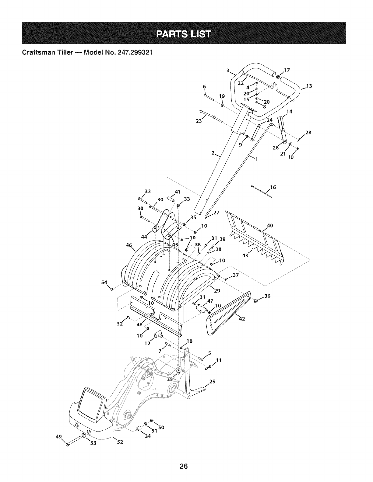
Craftsman Tiller B IViodel No. 247.299321
17
6
23
21
14
_\\ 7 28
/
7
10
46
\
32
3O
\
44
3O
_10
27
10
39
/
43
10
4O
54
/-"
p_36
18
25
49
\
-_\51 50
34
26
Craftsman Tiller B Model No. 247.299321
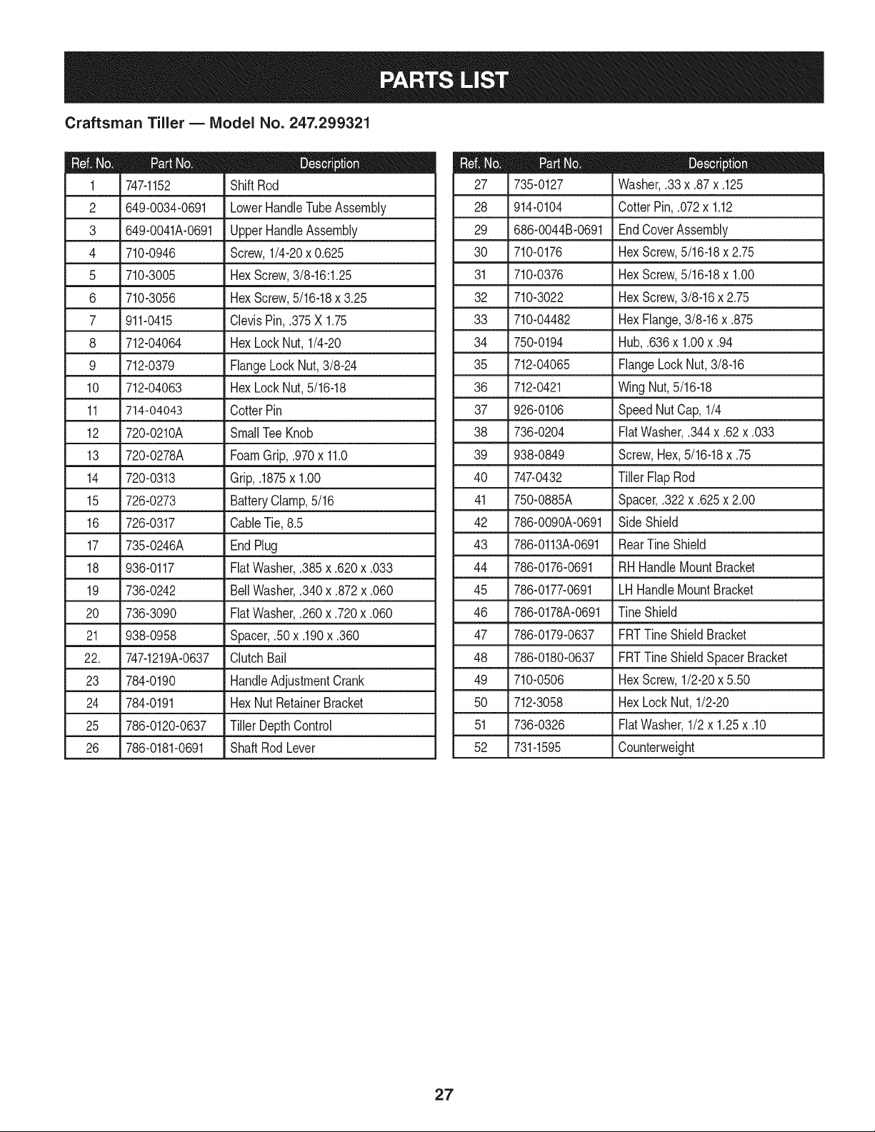
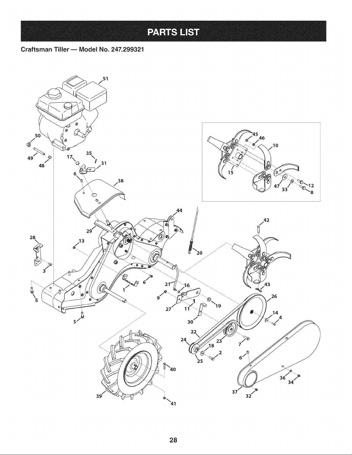
747-1152 Shift Rod
2 649-0034-0691 LowerHandleTubeAssembly 28
3 649-0041A-0691 UpperHandleAssembly 29
4 710-0946 Screw,1/4-20x 0.625 30
5 710-3005 Hex Screw,3/8-16:1.25 31
6 710-3056 Hex Screw,5/16-18x 3.25 32
7 911-0415 ClevisPin,.375X 1.75 33
8 712-04064 HexLockNut,1/4-20 34
9 712-0379 FlangeLock Nut,3/8-24 35
10 712-04063 HexLockNut,5/16-18 36
11 714-04043 CotterPin 37
12 720-0210A SmallTee Knob 38
13 720-0278A FoamGrip,.970x 11.0
14 720-0313 Grip,.1875x 1.00 40
15 726-0273 BatteryClamp,5/16 41
16 726-0317 CableTie, 8.5 42
17 735-0246A EndPlug 43
18 936-0117 FiatWasher,.385x .620x .033 44
19 736-0242 Bell Washer,.340x .872x .060 45
20 736-3090 FiatWasher,.260x .720x .060 46
21 938-0958 Spacer,.50x .190x .360 47
22. 747-1219A-0637 ClutchBail 48
23 784-0190 HandleAdjustmentCrank 49
24 784-0191 HexNutRetainerBracket 50
25 786-0120-0637 TillerDepthControl 51
26 786-0181-0691 ShaftRodLever 52
735-0127
914-0104
686-0044B-0691
710-0176
710-0376
710-3022
710-04482
750-0194
712-04065
712-0421
926-0106
736-0204
Washer,.33x .87x .125
CotterPin, .072x 1.12
EndCoverAssembly
HexScrew,5/16-18x 2.75
HexScrew,5/16-18x 1.00
HexScrew,3/8-16x 2.75
HexFlange,3/8-16x .875
Hub,.636x 1.00x .94
FlangeLock Nut,3/8-16
Wing Nut,5/16-18
SpeedNutCap,1/4
FiatWasher,.344x .62x .033
39 938-0849
747-0432
750-0885A
786-0090A-0691
786-0113A-0691
786-0176-0691
786-0177-0691
786-0178A-0691
Screw,Hex,5/16-18x .75
Tiller FlapRod
Spacer,.322x .625x 2.00
SideShield
RearTine Shield
RH HandleMountBracket
LH HandleMountBracket
TineShield
786-0179-0637
786-0180-0637
710-0506
712-3058
736-0326
731-1595
FRTTine ShieldBracket
FRTTine ShieldSpacerBracket
HexScrew,1/2-20x 5.50
HexLockNut, 1/2-20
FiatWasher,1/2x 1.25x .10
Counterweight
27
Craftsman Tiller- IViodel No. 247.299321
/
48
28
©
38
44
,\\
6
iO
/
30
22
24
/42
26
14
4
18
2
34
28
Craftsman Tiller B IViodel No. 247.299321
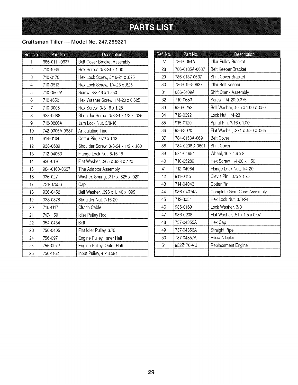
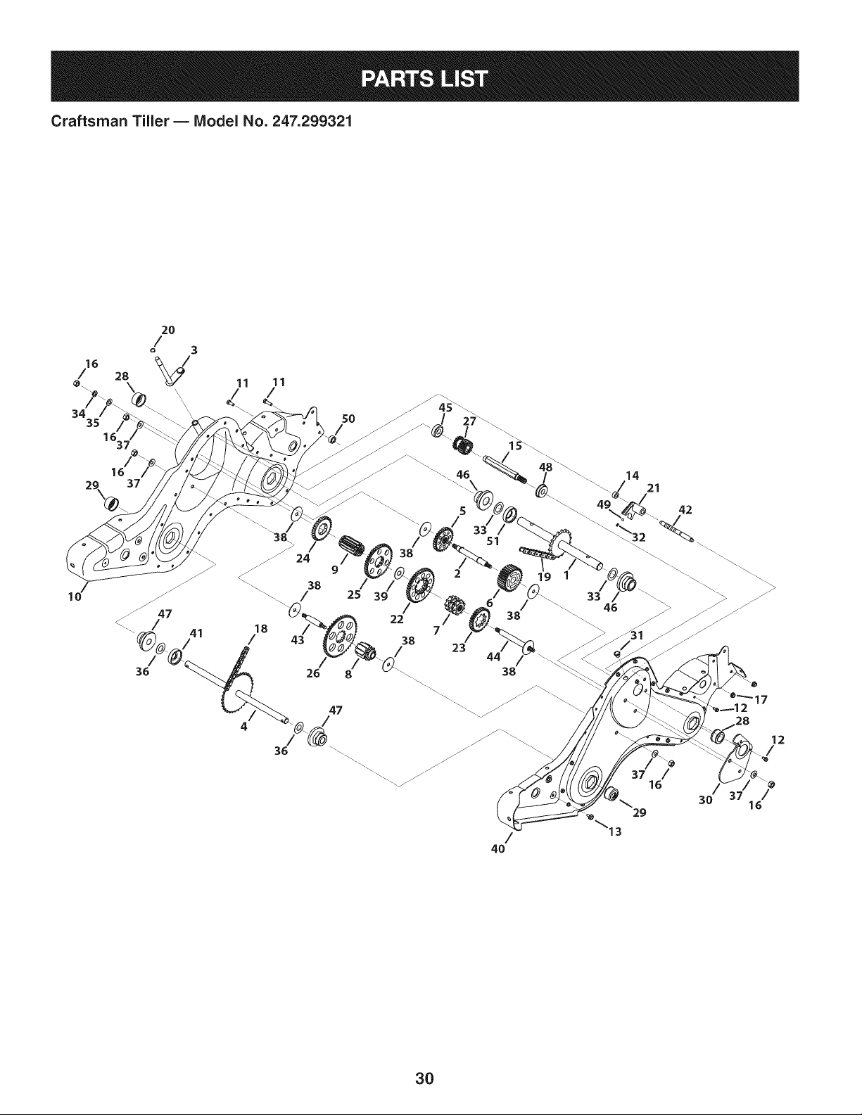
686-0111-0637 BeltCoverBracketAssembly
2 710-1039 Hex Screw,3/8-24 x 1.00
3 710-0170 Hex LockScrew,5/16-24x .625
4 710-0513 Hex LockScrew,1/4-28x .625 30
5 710-0502A Screw,3/8-16x 1.250 31
6 710-1652 HexWasherScrew,1/4-20x 0.625 32
7 710-3005 Hex Screw,3/8-16x 1.25 33
8 938-0688 ShoulderScrew,3/8-24x 1/2 x .325 34
9 712-0266A JamLockNut, 3/8-16 35
10 742-0305A-0637 ArticulatingTine 36
11 914-0104 CotterPin,.072x 1.13 37
12 938-0689 ShoulderScrew,3/8-24x 1/2 x .180 38
13 712-04063 FlangeLockNut,5/16-18 39
14 936-0176 FiatWasher,.265x .938x .120 40
15 984-0160-0637 TineAdaptorAssembly 41
16 936-0271 Washer,Spring,.317x .625x .020 42
17 731-07556 Cap 43
18 936-0452 Bell Washer,.396x 1.140x .095 44
19 938-0876 ShoulderNut,7/16-20 45
20 746-1117 ClutchCable
21 747-1159 IdlerPulleyRod
22 954-0434 Belt
23 756-0405 FiatIdlerPulley,3.75
24 756-0971 EnginePulley,InnerHalf
25 756-0972 EnginePulley,OuterHalf
26 756-1162 input Pulley,4 x 8.594
786-0064A Idler PulleyBracket
28 786-0185A-0637 Belt KeeperBracket
29 786-0187-0637 ShiftCoverBracket
786-0193-0637
686-0109A
710-0653
936-0253
712-0392
915-0120
936-3020
784-0158A-0691
784-0208D-0691
634-04654
710-05289
712-04064
911-0415
714-04043
986-04074A
712-3054
Idler BeltKeeper
ShiftCrankAssembly
Screw,1/4-20:0.375
BellWasher,.525x 1.00x .050
LockNut, 1/4-28
SpiralPin,3/16x 1.00
FiatWasher,.271x .630x .065
Belt Cover
ShiftCover
Wheel,16x 4.6 x 8
HexScrew,1/4-20x 1.50
FlangeLock Nut,1/4-20
ClevisPin, .375x 1.75
CotterPin
CompleteGearCaseAssembly
HexLockNut,3/8-24
46 936-0169 LockWasher,3/8
47 936-0208 FiatWasher,.51x 1.5x 0.07
48 737-04355A Hex Cap
49 737-04356A StraightPipe
50 737-04357A ElbowAdapter
51 952Z170-VU ReplacementEngine
29
Craftsman Tiller B IViodel No. 247.299321
16
29\_ 37
.\
10
11
/
50
46
.\
_13
/
4O
42
/
16
29
12
/
30 16
3O
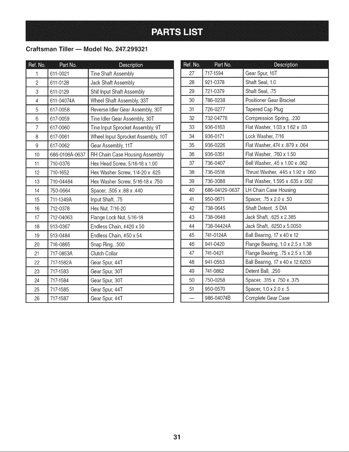
Craftsman Tiller B IViodel No. 247.299321
611-0021 TineShaft Assembly
2 611-0128 JackShaftAssembly 28
3 611-0129 Shif InputShaftAssembly 29
4 611-04074A WheelShaftAssembly,33T 30
5 617-0058 ReverseIdlerGearAssembly,30T 31
6 617-0059 TineIdler GearAssembly,30T 32
7 617-0060 Tineinput SprocketAssembly,9T 33
8 617-0061 WheelinputSprocketAssembly,10T 34
9 617-0062 GearAssembly,11T 35
10 686-0108A-0637 RH ChainCaseHousingAssembly 36
11 710-0376 HexHeadScrew,5/16-18x 1.00 37
12 710-1652 HexWasherScrew,1/4-20x .625 38
13 710-04484 HexWasherScrew,5/16-18x .750 39
14 750-0664 Spacer,.505x .88 x .440 40
15 711-1349A input Shaft,.75 41
16 712-0378 HexNut,7/16-20 42
17 712-04063 FlangeLockNut,5/16-18 43
18 913-0367 EndlessChain,#420x 50 44
19 913-0484 EndlessChain,#50 x 54 45
20 716-0865 SnapRing,.500 46
21 717-0853A ClutchCollar 47
22 717-1582A GearSpur,44T 48
23 717-1583 GearSpur,30T
24 717-1584 GearSpur,30T
25 717-1585 GearSpur,44T
26 717-1587 GearSpur,44T
717-1594 GearSpur,16T
921-0378 ShaftSeal, 1.0
721-0379 ShaftSeal,.75
786-0238 PositionerGearBracket
726-0277 TaperedCap Plug
732-04778 CompressionSpring,.230
936-0163
936-0171
936-0226
936-0351
736-0407
736-0518
736-3088
686-04129-0637
950-0671
738-0645
738-0648
738-04424A
741-0124A
941-0420
741-0421
941-0563
FiatWasher,1.03x 1.62x .03
LockWasher,7/16
FiatWasher,.474x .879x .064
FiatWasher,.760x 1.50
BellWasher,.45x 1.00x .062
ThrustWasher,.445x 1.92x .060
FiatWasher,1.595x .635x .062
LHChainCaseHousing
Spacer,.75x 2.0 x .50
ShaftDetent,.5 DIA
Jack Shaft,.625x 2.385
Jack Shaft,.6250x 5.0050
BallBearing,17x 40 x 12
FlangeBearing,1.0x 2.5 x 1.38
FlangeBearing,.75x 2.5 x 1.38
BallBearing,17x 40 x 12:6203
49 741-0862 DetentBall,.250
50 750-0258 Spacer,.315x .750x .375
51 950-0570 Spacer,1.0x 2.0x .5
-- 986-04074B CompleteGearCase
31
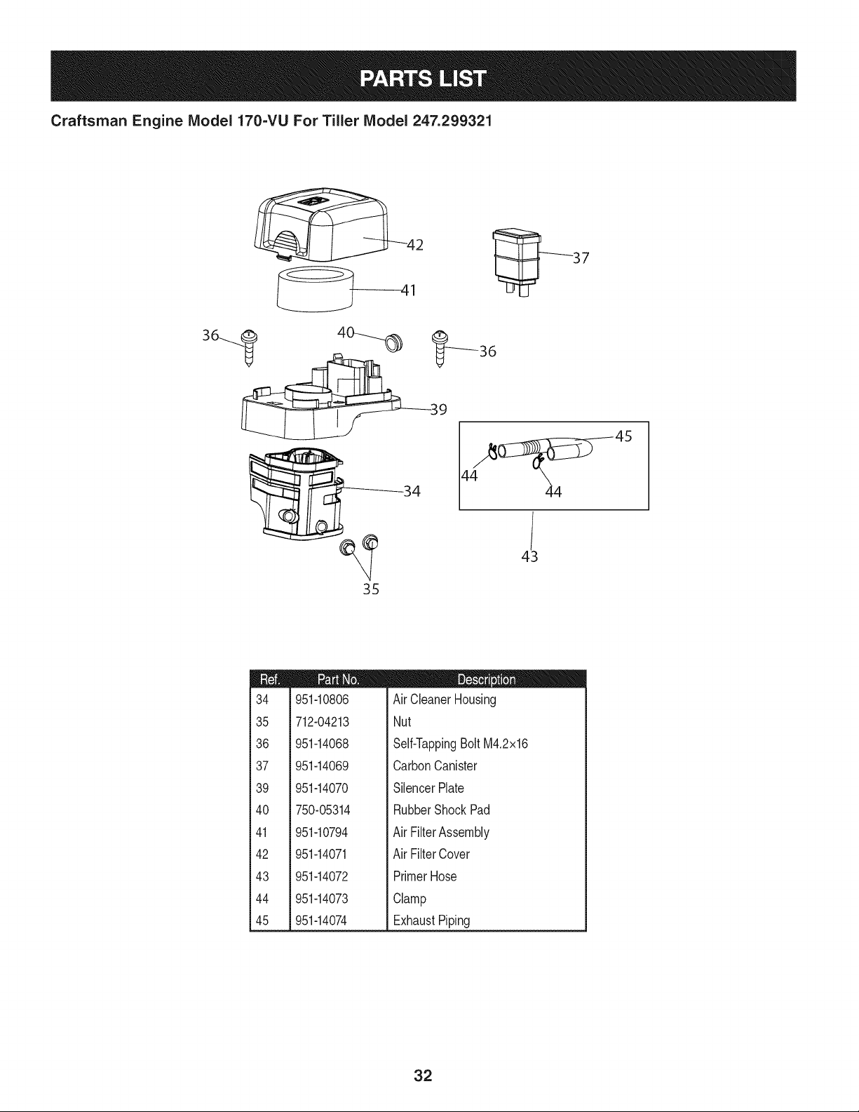
Craftsman Engine Model 170=VU For Tiller Model 247.299321
951-10806
712-04213
951-14068
951-14069
951-14070
750-05314
D = I! I!
AirCleanerHousing
Nut
Self-TappingBoltM4.2x16
CarbonCanister
SilencerPlate
RubberShockPad
951-10794
951-14071
951-14072
951-14073
951-14074
AirFilterAssembly
AirFilterCover
PrimerHose
Clamp
ExhaustPiping
32
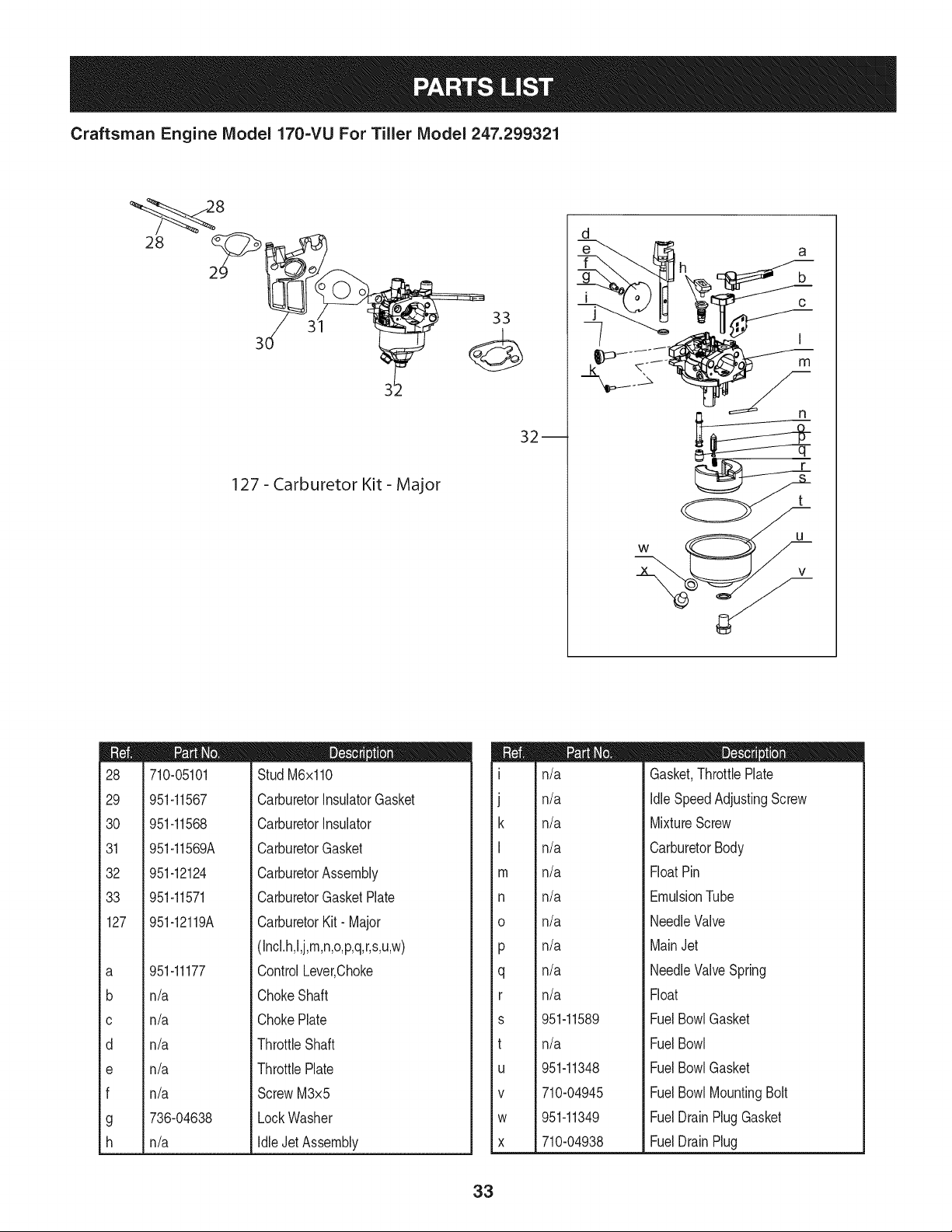
Craftsman Engine IViodel 170-VU For Tiller IViodel 247.299321
28
32--
127 - Carburetor Kit - Major
d
m
28
29
30
31
32
33
127
a
b
C
d
e
f
g
h
710-05101
951-11567
951-11568
951-11569A
951-12124
951-11571
951-12119A
D = 0 O
Stud M6x110
CarburetorInsulatorGasket
CarburetorInsulator
CarburetorGasket
CarburetorAssembly
CarburetorGasketPlate
CarburetorKit- Major
(Incl.h,l,j,m,n,o,p,q,r,s,u,w)
951-11177
n/a
n/a
n/a
n/a
n/a
736-04638
n/a
ControlLever,Choke
ChokeShaft
ChokePlate
ThrottleShaft
ThrottlePlate
ScrewM3x5
LockWasher
IdleJet Assembly
m
m
]
k
I
m
n
o
P
q
r
s
t
U
V
W
X
n/a
n/a
n/a
n/a
n/a
n/a
n/a
n/a
n/a
n/a
951-11589
n/a
951-11348
710-04945
951-11349
710-04938
m = O O
Gasket,ThrottlePlate
IdleSpeedAdjustingScrew
MixtureScrew
CarburetorBody
FloatPin
EmulsionTube
NeedleValve
MainJet
NeedleValveSpring
Float
FuelBowlGasket
FuelBowl
FuelBowlGasket
FuelBowlMountingBolt
FuelDrainPlugGasket
FuelDrainPlug
33
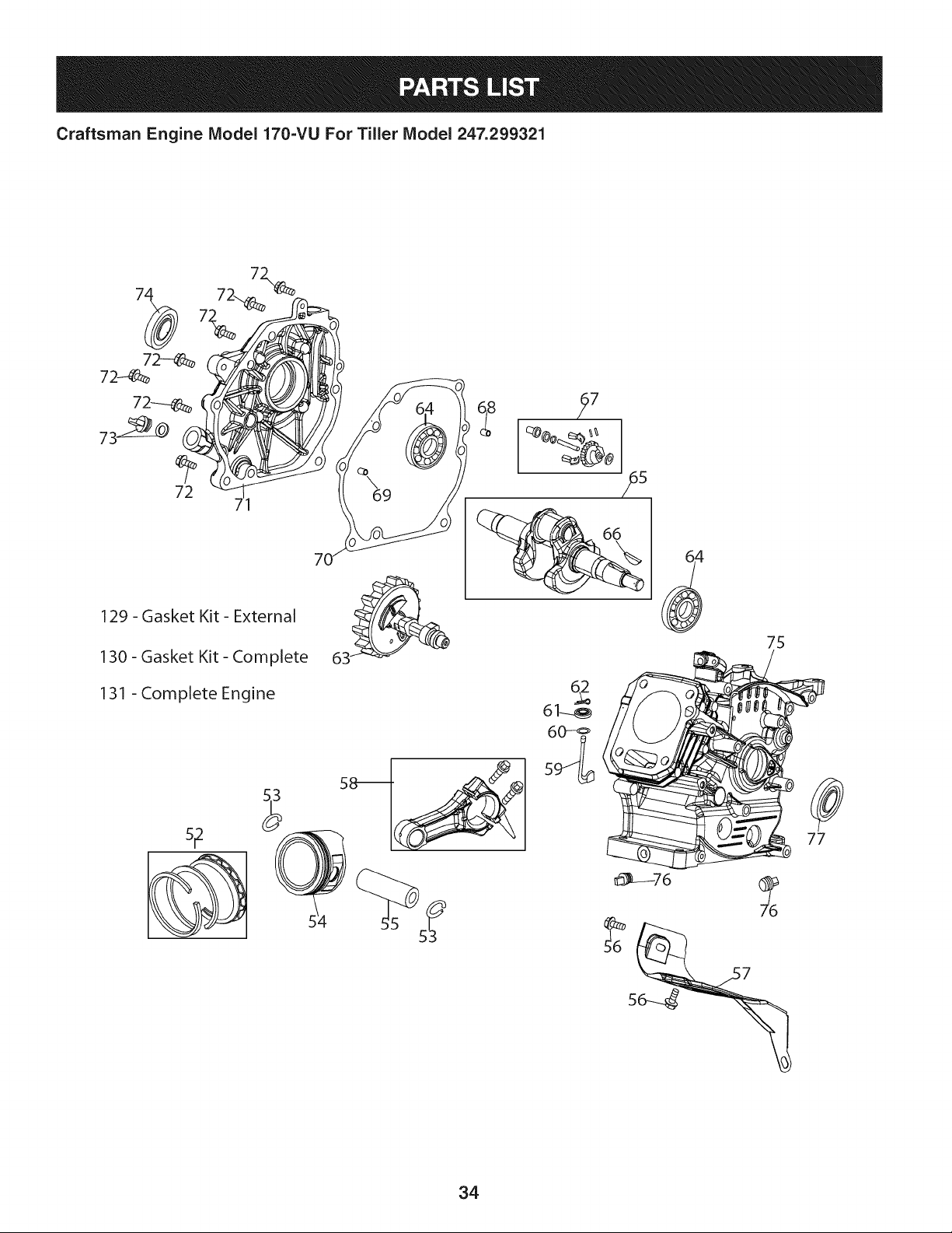
Craftsman Engine Model 170=VU For Tiller Model 247.299321
72
71
129 - Gasket Kit - External
130 - Gasket Kit - Complete
131 -Complete Engine
61_
60-_
75
77
34
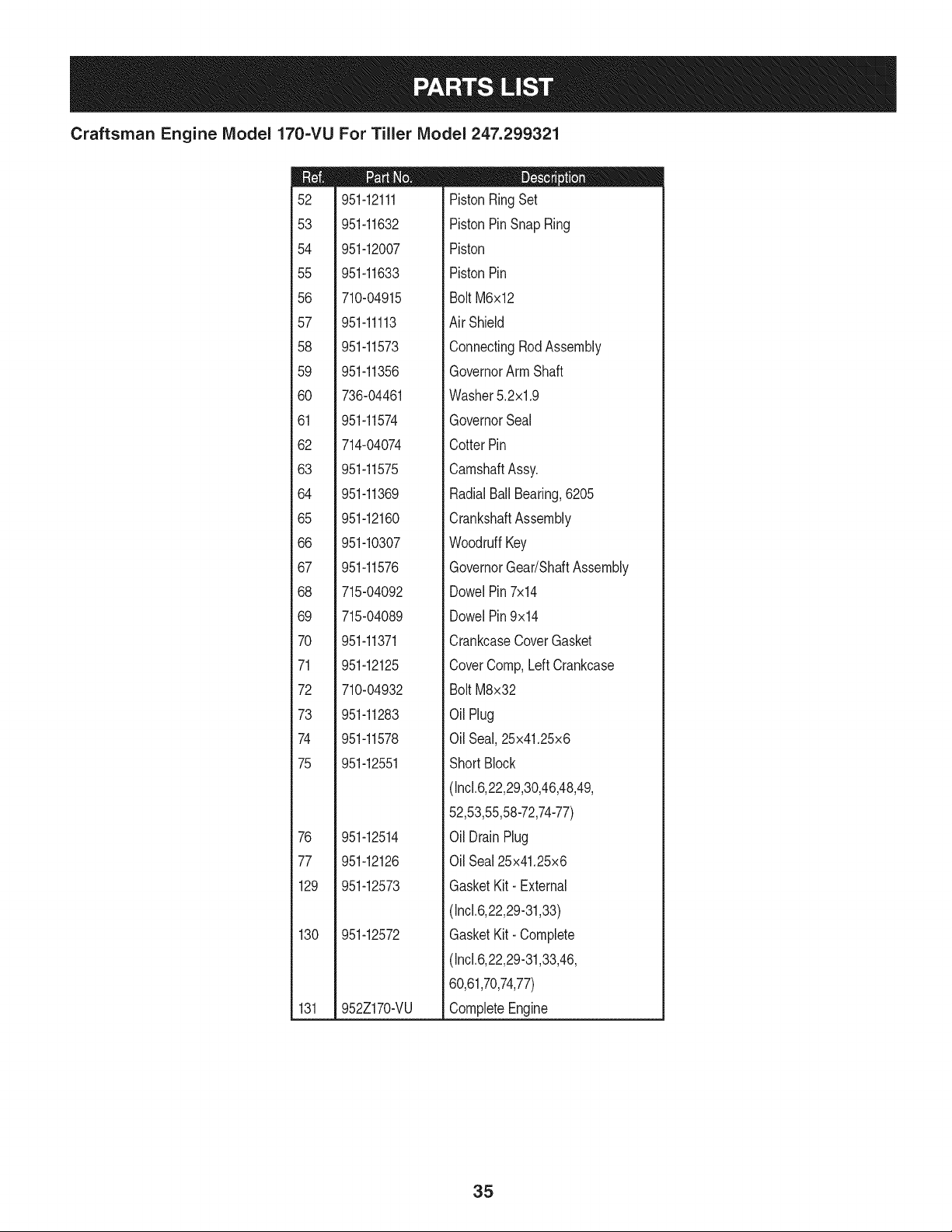
Craftsman Engine IViodel 170=VU For Tiller IViodel 247.299321
m
52
53
54
55
56
57
58
59
6O
61
62
63
64
65
66
67
68
69
7O
71
72
73
74
75
76
77
129
130
131
951-12111
951-11632
951-12007
951-11633
710-04915
951-11113
951-11573
951-11356
736-04461
951-11574
714-04074
951-11575
951-11369
951-12160
951-10307
951-11576
715-04092
715-04089
951-11371
951-12125
710-04932
951-11283
951-11578
951-12551
951-12514
951-12126
951-12573
951-12572
952Z170-VU
m = O O
PistonRingSet
PistonPinSnapRing
Piston
PistonPin
Bolt M6x12
Air Shield
ConnectingRodAssembly
GovernorArm Shaft
Washer5.2xl.9
GovernorSeal
CotterPin
CamshaftAssy.
RadialBall Bearing,6205
CrankshaftAssembly
WoodruffKey
GovernorGear/ShaftAssembly
DowelPin7x14
DowelPin9x14
CrankcaseCoverGasket
CoverComp,LeftCrankcase
Bolt M8x32
OilPlug
OilSeal,25x41.25x6
ShortBlock
(Incl.6,22,29,30,46,48,49,
52,53,55,58-72,74-77)
OilDrain Plug
OilSeal25x41.25x6
GasketKit- External
(Incl.6,22,29-31,33)
GasketKit- Complete
(Incl.6,22,29-31,33,46,
60,61,70,74,77)
CompleteEngine
35
Craftsman Engine Model 170-VU For Tiller Model 247.299321
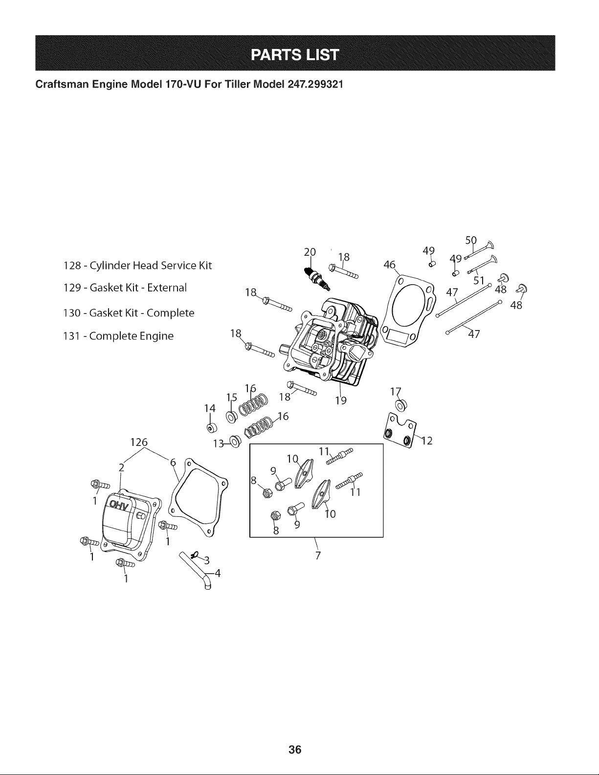
128 - Cylinder Head Service Kit
129 - Gasket Kit - External
130 - Gasket Kit - Complete
131 - Complete Engine
126
2 _
1
1
2O
\
7
36
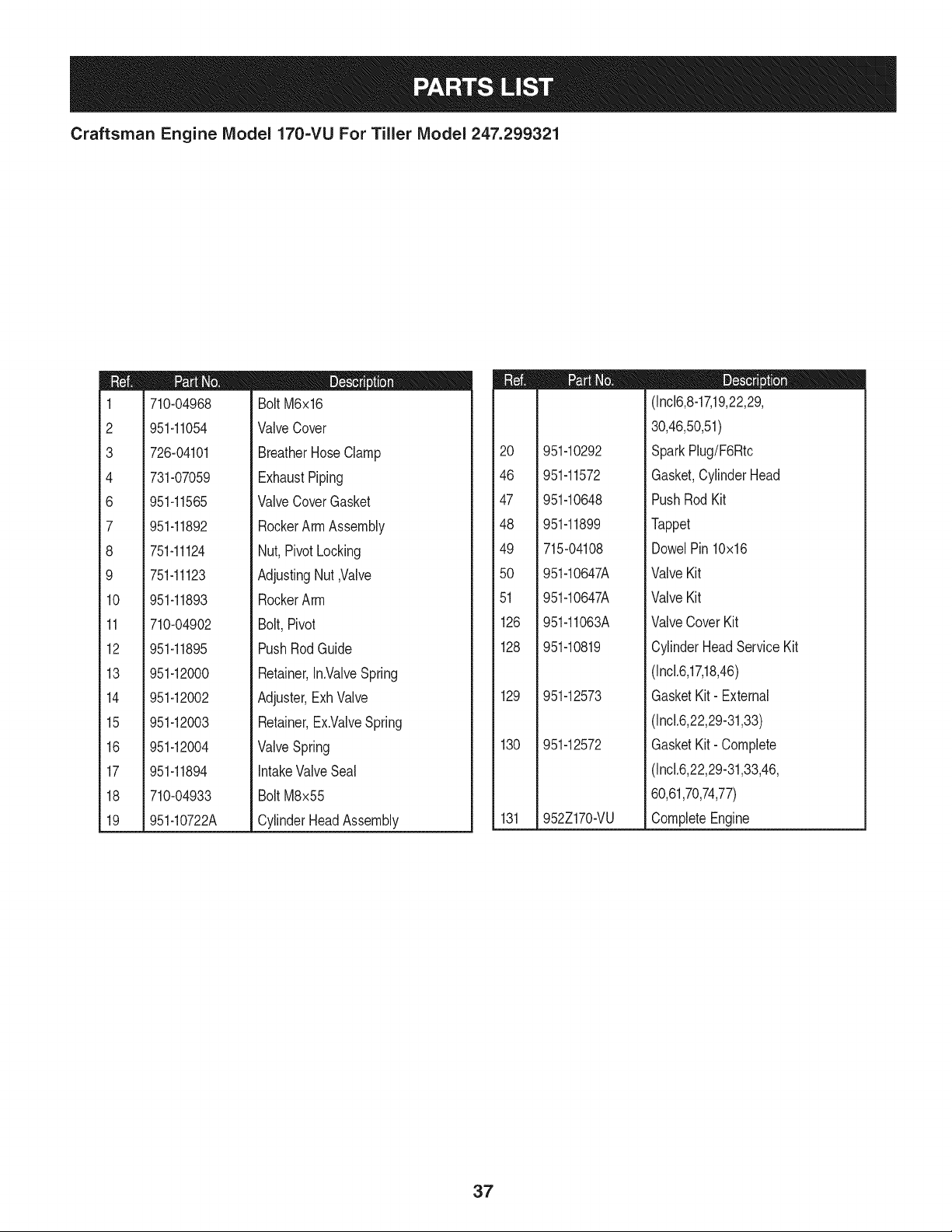
Craftsman Engine IViodel 170=VU For Tiller IViodel 247.299321
m
1
2
3
4
6
7
8
9
10
11
12
13
14
15
16
17
18
19
710-04968
951-11054
726-04101
731-07059
951-11565
951-11892
751-11124
751-11123
951-11893
710-04902
951-11895
951-12000
951-12002
951-12003
951-12004
951-11894
710-04933
951-10722A
D = B 0
BoltM6x16
ValveCover
BreatherHoseClamp
ExhaustPiping
ValveCoverGasket
RockerArmAssembly
Nut,Pivot Locking
AdjustingNut,Valve
RockerArm
Bolt,Pivot
PushRodGuide
Retainer,In.ValveSpring
Adjuster,ExhValve
Retainer,Ex.ValveSpring
ValveSpring
IntakeValveSeal
BoltM8x55
CylinderHeadAssembly
m
2O
46
47
48
49
5O
51
126
128
129
130
131
951-10292
951-11572
951-10648
951-11899
715-04108
951-10647A
951-10647A
951-11063A
951-10819
951-12573
951-12572
952Z170-VU
D = O
(Incl6,8-17,19,22,29,
30,46,50,51)
SparkPlug/F6Rtc
Gasket,CylinderHead
PushRodKit
Tappet
DowelPin10x16
ValveKit
ValveKit
ValveCoverKit
CylinderHeadServiceKit
(Incl.6,17,18,46)
GasketKit- External
(Incl.6,22,29-31,33)
GasketKit- Complete
(Incl.6,22,29-31,33,46,
60,61,70,74,77)
CompleteEngine
37
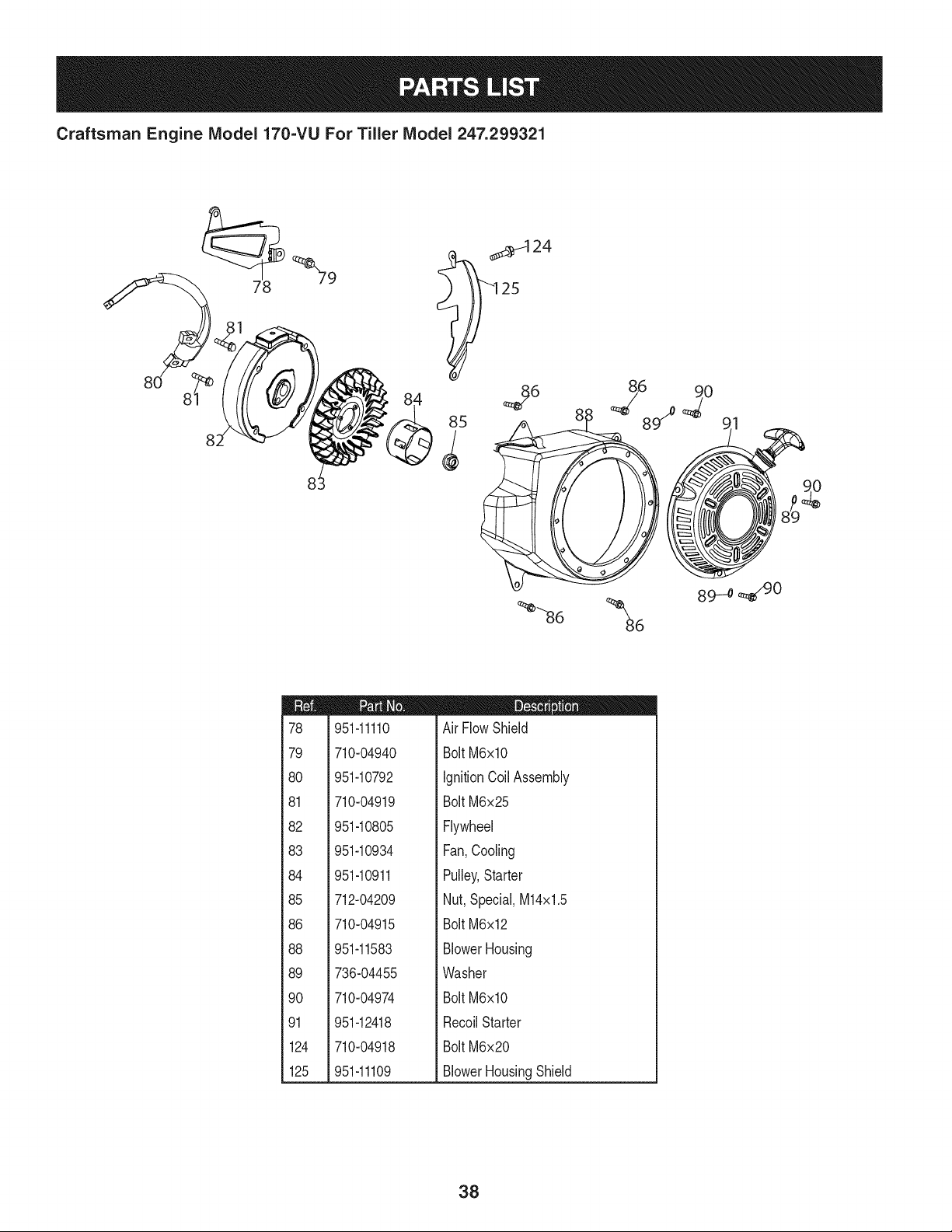
Craftsman Engine Model 170-VUFor Tiller Model 247.299321
78
82
_124
8 -o
m
78
79
8O
81
82
83
84
85
86
88
89
90
91
124
125
951-11110
710-04940
951-10792
710-04919
951-10805
951-10934
951-10911
712-04209
710-04915
951-11583
736-04455
710-04974
951-12418
710-04918
951-11109
D = " O O
Air FlowShield
BoltM6xlO
IgnitionCoil Assembly
BoltM6x25
Flywheel
Fan,Cooling
Pulley,Starter
Nut,Special,M14x1.5
BoltM6x12
BlowerHousing
Washer
BoltM6xlO
RecoilStarter
BoltM6x20
BlowerHousingShield
38
Craftsman Engine IViodel 170-VU For Tiller IViodel 247.299321
20
m
1
3
92
93
94
95
96
97
99
100
101
102
103
104
105
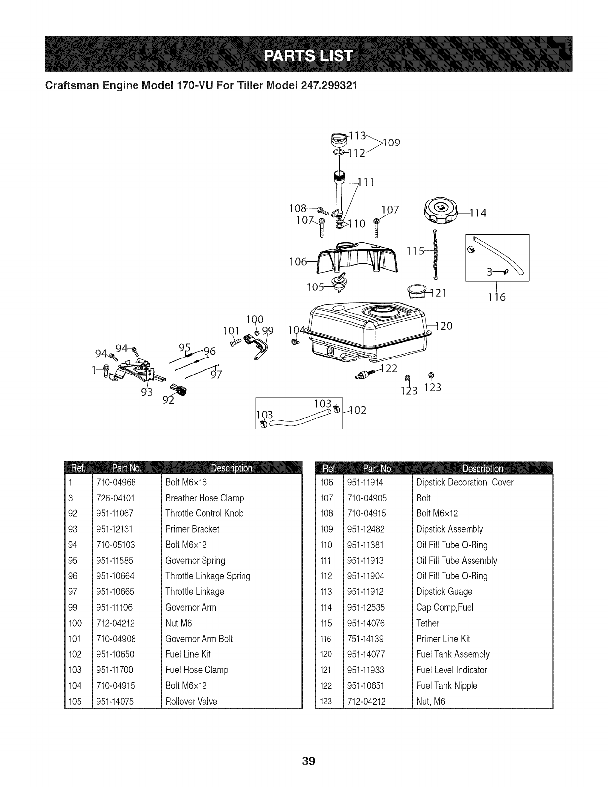
710-04968
726-04101
951-11067
951-12131
710-05103
951-11585
951-10664
951-10665
951-11106
712-04212
710-04908
951-10650
951-11700
710-04915
951-14075
m = B
BoltM6x16
BreatherHose Clamp
ThrottleControlKnob
PrimerBracket
BoltM6x12
GovernorSpring
ThrottleLinkageSpring
ThrottleLinkage
GovernorArm
NutM6
GovernorArmBolt
FuelLine Kit
FuelHoseClamp
BoltM6x12
RolloverValve
m
106
107
108
109
110
111
112
113
114
115
116
120
121
122
123
951-11914
710-04905
710-04915
951-12482
951-11381
951-11913
951-11904
951-11912
951-12535
951-14076
751-14139
951-14077
951-11933
951-10651
712-04212
D = O e
DipstickDecorationCover
Bolt
Bolt M6x12
DipstickAssembly
Oil FillTubeO-Ring
Oil FillTubeAssembly
Oil FillTubeO-Ring
DipstickGuage
CapComp,Fuel
Tether
PrimerLine Kit
FuelTankAssembly
FuelLevelIndicator
FuelTankNipple
Nut, M6
39
Craftsman Engine IViodel 170=VU For Tiller IViodel 247.299321
26
23
27
22
24
21
m
21
22
23
24
25
26
27
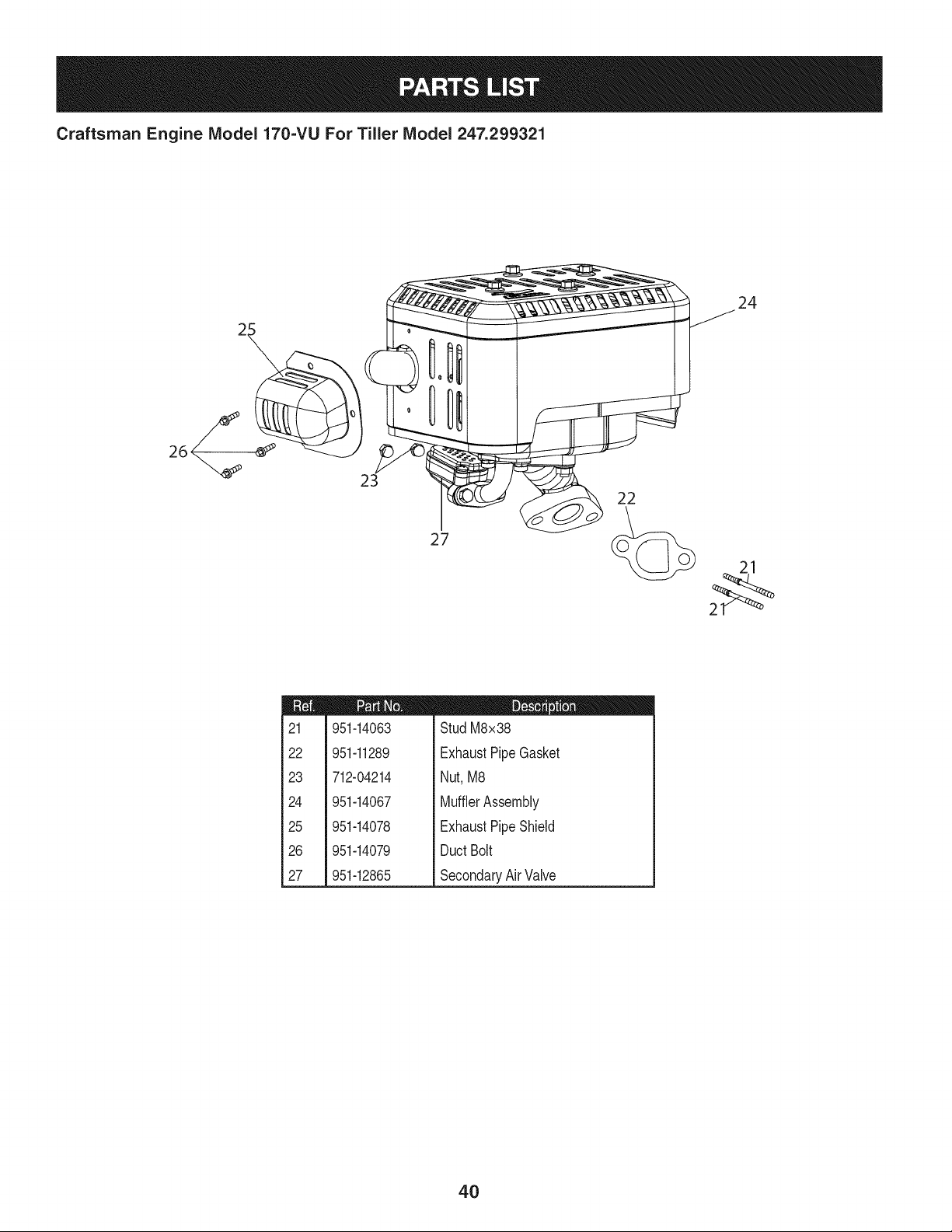
951-14063
951-11289
712-04214
951-14067
951-14078
951-14079
951-12865
D = W O
StudM8x38
ExhaustPipeGasket
Nut,M8
MufflerAssembly
ExhaustPipeShield
DuctBolt
SecondaryAirValve
4O
Craftsman Tiller Model No. 247.299321
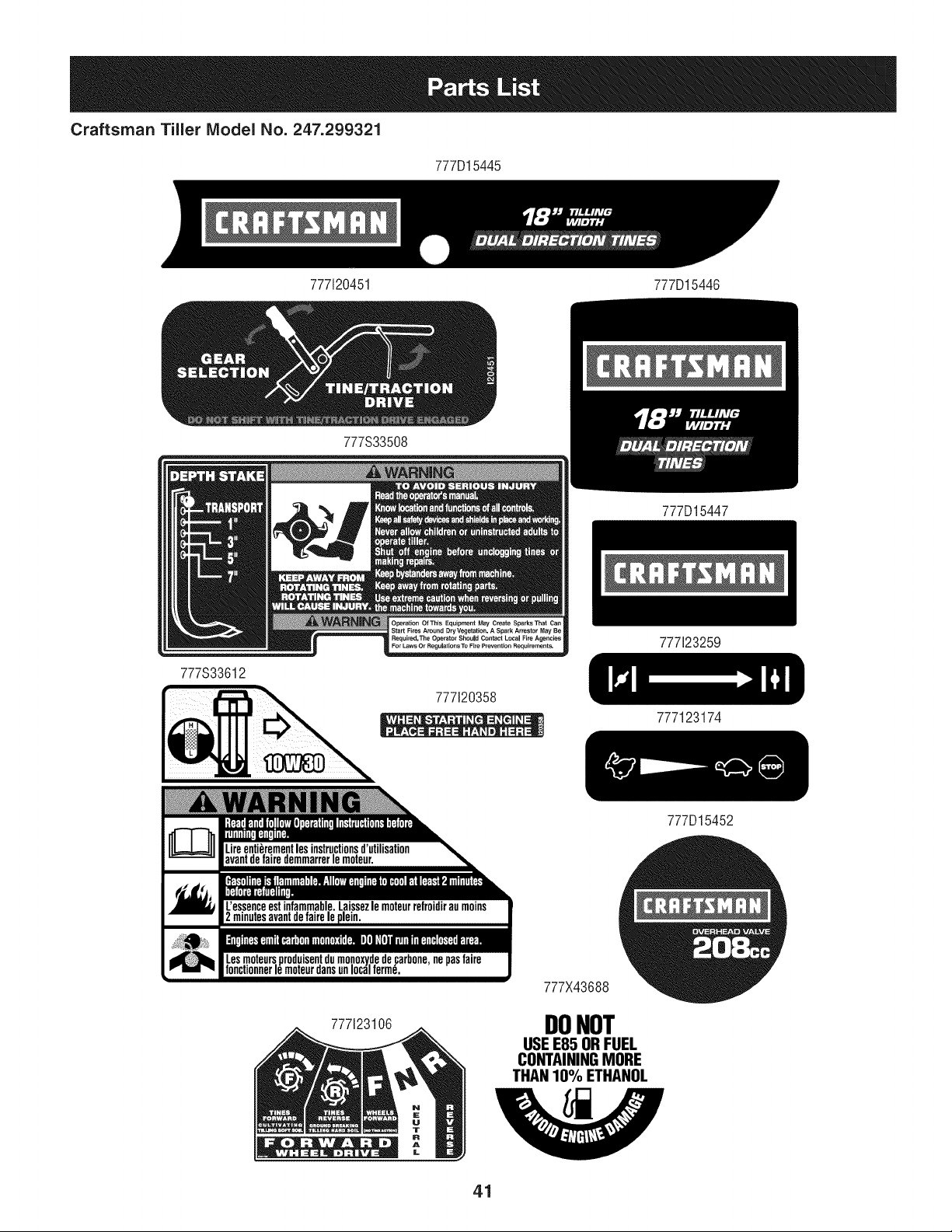
777D15445
777120451 777D15446
777S33508
777S33612
Operation Of This Equipment May Cre_e Sparks That
Start Fires Around Dry Vegetattsn. A Spark Arrestor May Be
Required, The Operator Should Contact Local Fire Agencies
For Laws Or Regulations TO Fire Prevention Requirements.
777120358
777D15447
777123259
777123174
777D15452
777123106
777X43688
DONOT
USEE85 ORFUEL
CONTAININGMORE
THAN10% ETHANOL
41
(Thispageapplicableinthe U.S.A.and Canadaonly.)
Sears Brands Management Corporation (Sears), the California Air Resources Board (CARD)
and the United States Environmental Protection Agency (U.S. EPA)
Emission Control System Warranty Statement (Owner's Defect Warranty Rights and Obligations)
EMISSIONCONTROLWARRANTYCOVERAGEISAPPLICABLETO CERTI-
FIEDENGINESPURCHASEDIN CALIFORNIAIN1995ANDTHEREAF-
TER,WHICHARE USEDINCALIFORNIA,ANDTOCERTIFIEDMODEL
California and United States Emission
The CaliforniaAir ResourcesBoard(CARD),U.S.EPAand Searsare pleased
to explainthe EmissionControlSystemWarrantyon your modelyear2000and
latersmalloff-roadengine(SORE).InCalifornia,newsmall off-roadengines
mustbe designed,builtand equippedto meettheState'sstringentanti-smog
standards.Elsewherein the UnitedStates, newnon-road,spark-ignition
enginescertifiedfor modelyear 1997and latermustmeetsimilarstandardsset
forth bythe U.S.EPA.Searsmustwarranttheemissioncontrol systemon your
YEAR 1997AND LATERENGINESWHICHARE PURCHASEDAND USED
ELSEWHEREIN THE UNITEDSTATES(ANDAFTERJANUARY1,2001 IN
CANADA).
Control Defects Warranty Statement
enginefor theperiodsoftime listedbelow,providedtherehas been noabuse,
neglector impropermaintenanceof your smalloff-roadengine.Youremis-
sion controlsystemincludespartssuch as thecarburetor,air cleaner,ignition
system,mufflerand catalyticconverter.Also includedmaybe connectorsand
otheremissionrelatedassemblies.Wherea warrantableconditionexists,Sears
will repairyour smalloff-roadengineat no costto you includingdiagnosis,parts
and labor.
Sears Emission Control Defects Warranty Coverage
Smalloff-roadenginesarewarrantedrelativeto emissioncontrol partsdefects
fora period of one year,subjectto provisionsset forthbelow.Ifany covered
Owner's Warranty
Asthe smalloff-roadengine owner,you are responsiblefor theperformanceof
therequiredmaintenancelistedin yourOperatingand MaintenanceInstruc-
tions.Searsrecommendsthatyou retain all yourreceiptscoveringmaintenance
on yoursmalloff-roadengine,but Sears cannotdenywarrantysolelyfor the
lackof receiptsor for yourfailureto ensurethe performanceof all scheduled
maintenance.As the smalloff-roadengineowner,you shouldhoweverbe
awarethat Searsmay denyyou warrantycoverageifyour smalloff-roadengine
ora part hasfaileddueto abuse,neglect,impropermaintenanceor unap-
parton yourengineis defective,the part will be repairedorreplacedbySears.
Responsibilities
provedmodifications.Youare responsiblefor presentingyour smalloff-road
engineto an AuthorizedSearsServiceDealeras soonas a problemexists.The
undisputedwarrantyrepairsshouldbe completedina reasonableamountof
time,notto exceed30 days.Ifyou haveany questionsregardingyourwarranty
rightsand responsibilities,youshouldcontacta SearsService Representative
at 1-800-469-4663.The emissionwarrantyis a defectswarranty.Defectsare
judgedon normalengineperformance.The warrantyis notrelatedto an in-use
emissiontest.
Sears Emission Control Defects Warranty Provisions
ThefollowingarespecificprovisionsrelativetoyourEmissionControlDefectsWarrantyCoverage.Itisin additiontotheSearsenginewarrantyfornon-regulated
enginesfoundin theOperatingand MaintenanceInstructions.
1. WarrantedParts
Coverageunderthis warrantyextendsonly to the parts listedbelow (the
emissioncontrolsystemsparts)to the extentthese partswere presenton
theengine purchased.
a. FuelMeteringSystem
• Cold start enrichmentsystem
• Carburetorand internalparts
• FuelPump
b. Air lnduction System
• Air cleaner
• Intakemanifold
c. IgnitionSystem
• Spark plug(s)
• Magnetoignitionsystem
d. CatalystSystem
• Catalyticconverter
• Exhaustmanifold
• Air injectionsystemor pulsevalve
e. MiscellaneousItemsUsedin AboveSystems
• Vacuum,temperature,position,time sensitivevalves
andswitches
• Connectorsandassemblies
2. Lengthof Coverage
Searswarrantsto the initialownerand eachsubsequentpurchaserthat
theWarrantedPartsshallbe free from defects in materialsandworkman-
shipwhich causedthefailure of the WarrantedPartsfor a period of one
yearfrom the datethe engineis deliveredto a retailpurchaser.
3. NoCharge
Repairor replacementof anyWarrantedPartwill beperformedat no
chargeto the owner,includingdiagnosticlabor whichleadsto the
determinationthata WarrantedPartis defective,if the diagnosticwork is
performedat an AuthorizedSears ServiceDealer.For emissionswarranty
servicecontact yournearestAuthorizedSears ServiceDealeras listed in
the "YellowPages"under"Engines,Gasoline,""GasolineEngines,""Lawn
Mowers,"orsimilarcategory.
4. Claimsand CoverageExclusions
Warrantyclaimsshall be filed in accordancewiththe provisionsof the
Sears EngineWarrantyPolicy.Warrantycoverageshall be excludedfor
failuresof WarrantedPartswhichare notoriginal Sears partsor because
of abuse,neglector impropermaintenanceas setforth inthe Sears
EngineWarrantyPolicy.Sears is notliableto coverfailuresof Warranted
Partscausedby theuse of add-on, non-original,or modifiedparts.
5. Maintenance
Any WarrantedPart whichis not scheduledfor replacementas required
maintenanceor whichis scheduledonly for regularinspectionto the effect
of "repairor replaceas necessary"shallbe warrantedas to defectsfor the
warrantyperiod.Any WarrantedPartwhich is scheduledfor replacement
as requiredmaintenanceshallbe warrantedas to defectsonly forthe
periodof time upto the firstscheduledreplacementfor that part. Any
replacementpart that is equivalentin performanceand durabilitymay
be usedin the performanceof any maintenanceor repairs.The owneris
responsibleforthe performanceof all requiredmaintenance,as definedin
the SearsOperatingand MaintenanceInstructions.
6. ConsequentialCoverage
Coveragehereundershallextend to the failure of any engine components
caused bythe failureof any WarrantedPartstill underwarranty.
Inthe USAandCanada,a 24 hour hot line, 1-800-469-4663,has a menu of pre-recordedmessagesofferingyou enginemaintenanceinformation.
GDOC-100188Rev.B
42
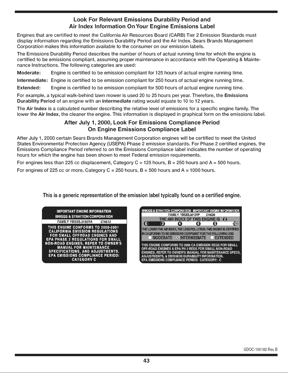
Look For Relevant Emissions Durability Period and
Air index information On Your Engine Emissions Label
Engines that are certified to meet the California Air Resources Board (CARB) Tier 2 Emission Standards must
display information regarding the Emissions Durability Period and the Air Index. Sears Brands Management
Corporation makes this information available to the consumer on our emission labels.
The Emissions Durability Period describes the number of hours of actual running time for which the engine is
certified to be emissions compliant, assuming proper maintenance in accordance with the Operating & Mainte-
nance Instructions. The following categories are used:
Moderate: Engine is certified to be emission compliant for 125 hours of actual engine running time.
Intermediate: Engine is certified to be emission compliant for 250 hours of actual engine running time.
Extended: Engine is certified to be emission compliant for 500 hours of actual engine running time.
For example, a typical walk-behind lawn mower is used 20 to 25 hours per year. Therefore, the Emissions
Durability Period of an engine with an intermediate rating would equate to 10 to 12 years.
The Air index is a calculated number describing the relative level of emissions for a specific engine family. The
lower the Air Index, the cleaner the engine. This information is displayed in graphical form on the emissions label.
After July 1,2000, Look For Emissions Compliance Period
On Engine Emissions Compliance Label
After July 1, 2000 certain Sears Brands Management Corporation engines will be certified to meet the United
States Environmental Protection Agency (USEPA) Phase 2 emission standards. For Phase 2 certified engines, the
Emissions Compliance Period referred to on the Emissions Compliance label indicates the number of operating
hours for which the engine has been shown to meet Federal emission requirements.
For engines less than 225 cc displacement, Category C = 125 hours, B = 250 hours and A = 500 hours.
For engines of 225 cc or more, Category C = 250 hours, B = 500 hours and A = 1000 hours.
This is a generic representation of the emission label typically found on a certified engine.
FAMILYYBSXS.3192VA 274812
GDOC-100182Rev.B
43
Congratulations on making a smart purchase. Your new Craftsman® product is designed and
manufactured for years of dependable operation. But like all products, it may require repair
from time to time. That's when having a Repair Protection Agreement can save you money and
aggravation.
Here's what the Repair Protection Agreement* includes:
[] Expert service by our 10,000 professional repair specialists
[] Unlimited service and no charge for parts and labor on all covered repairs
[] Product replacement up to $1500 if your covered product can't be fixed
[] Discount of 25% from regular price of service and related installed parts not covered by the
agreement; also, 25% off regular price of preventive maintenance check
[] Fast help by phone - we call it Rapid Resolution - phone support from a Sears representative.
Think of us as a "talking owner's manual."
Once you purchase the Repair Protection Agreement, a simple phone call is all that it takes for you
to schedule service. You can call anytime day or night, or schedule a service appointment online.
The Repair Protection Agreement is a risk-free purchase. If you cancel for any reason during the
product warranty period, we will provide a full refund. Or, a prorated refund anytime after the
product warranty period expires. Purchase your Repair Protection Agreement today!
Some limitations and exclusions apply. For prices and additional information in the U.S.A.
call 1=800=827=6655.
*Coverage in Canada varies on some items. For full details call Sears Canada at 1=800=361=
6665.
Sears Installation Service
For Sears professional installation of home appliances, garage door openers, water heaters, and
other major home items, in the U.S.A. or Canada call 1=800=4=MY=HOME®.
44
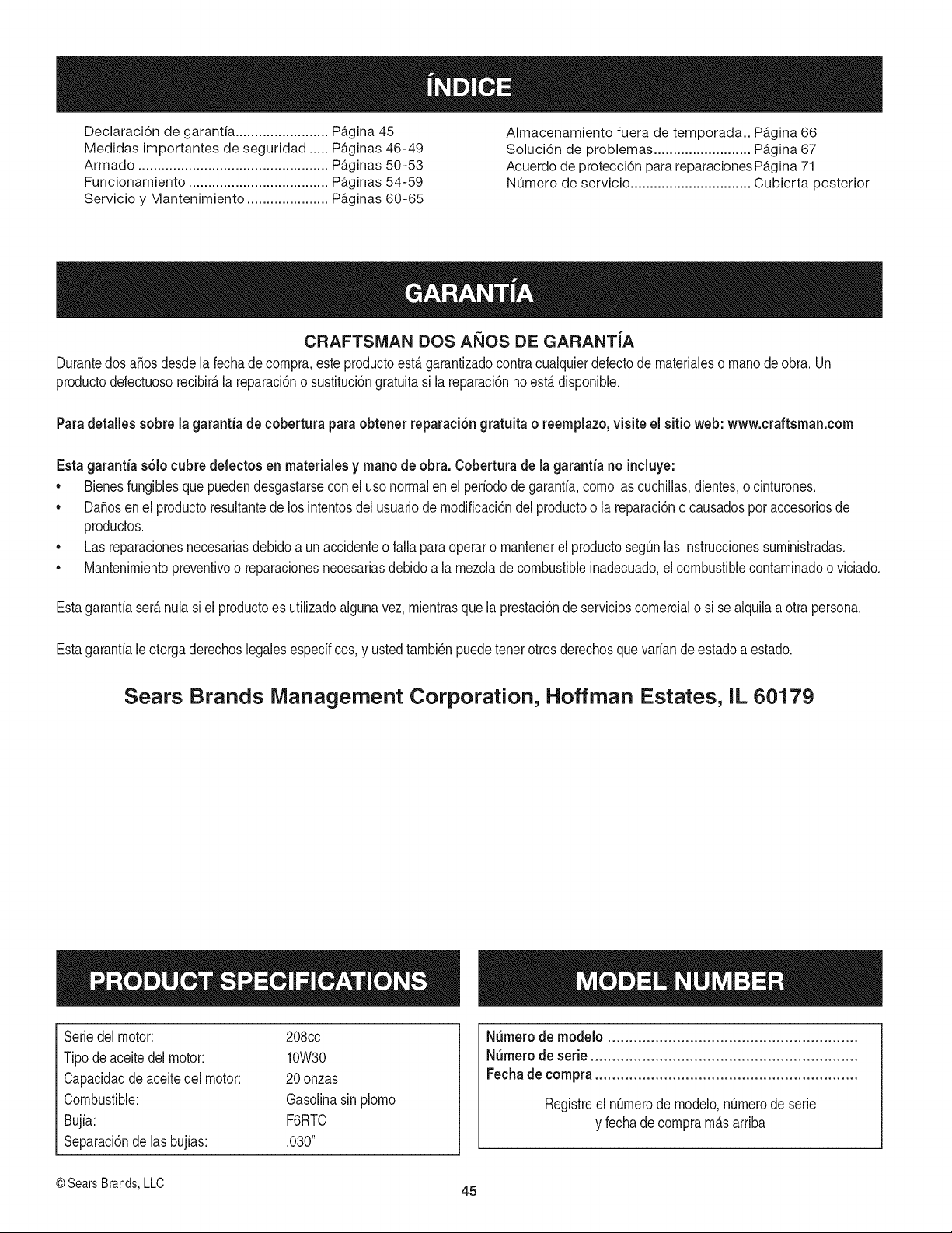
Declaraci6n de garantia ........................ Pb,gina 45
Medidas importantes de seguridad ..... Pb,ginas 46-49
Armado ................................................. Pb,ginas 50-53
Funcionamiento .................................... Pb,ginas 54-59
Servicio y Mantenimiento ..................... P_.ginas 60-65
Almacenamiento fuera de temporada.. Pb,gina 66
Soluci6n de problemas ......................... P_,gina 67
Acuerdo de protecci6n para reparaciones Pb,gina 71
NQmero de servicio ............................... Cubierta posterior
CRAFTSMAN DOS AltOS DE GARANTJA
Durantedos aSosdesdela fechade compra,esteproductoest_garantizadocontracualquierdefectode materialeso manodeobra. Un
productodefectuosorecibir_la reparaci6no sustituci6ngratuitasi la reparaci6nnoest_disponible.
Paradetalles sobre la garantia de coberturaparaobtener reparaci6ngratuita o reemplazo,visite el sitio web: www.craftsman.com
Esta garantias61ocubre defectos en rnateriaiesy mano de obra. Cobertura de la garantiano ineiuye:
• Bienesfungiblesque puedendesgastarsecon el usonormalenel periodode garantia,comolas cuchillas,dientes,o cinturones.
• DaSosenel productoresultantede los intentosdel usuariode modificaci6ndel productoo la reparaci6no causadosporaccesoriosde
productos.
• Las reparacionesnecesariasdebidoa un accidenteo falla paraoperaro mantenerel productoseg0nlas instruccionessuministradas.
• Mantenimientopreventivoo reparacionesnecesariasdebido a la mezclade combustibleinadecuado,eJcombustiblecontaminadoo viciado.
Estagaranfiaser_nulasi el productoes utilizadoalgunavez, mientrasque la prestaci6nde servicioscomercialo si se alquilaa otra persona.
Estagaranfiale otorgaderechoslegalesespecificos,y ustedtambi_npuedetenerotrosderechosquevariandeestadoa estado.
Sears Brands Management Corporation, Hoffman Estates, IL 60179
Seriedel motor: 208cc
Tipode aceite del motor: 10W30
Capacidadde aceitedel motor: 20onzas
Combustible: GasoJinasin plomo
Bujia: F6RTC
Separaci6nde las bujias: .030"
NSmerode modelo ..........................................................
NSmerode serie ..............................................................
Fechade compra .............................................................
Registreel n0merodemodelo,nQmerode serie
y fechade compram_sarriba
@Sears Brands,LLC 45
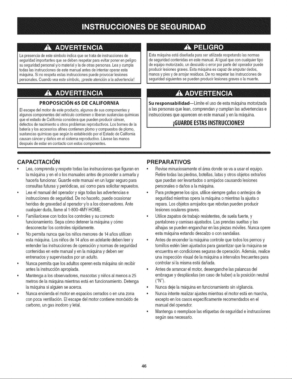
Lapresenciadeestesimboloindicaquesetratadeinstruccionesde
seguridadimportantesquesedebenrespetarparaevitarponerenpeligro
suseguridadpersonaly/omaterialyladeotraspersonas.Leaycumpla
todaslasinstruccionesdeestemanualantesdeintentaroperaresta
m&quina.Sinorespetaestasinstruccionespuedeprovocarlesiones
personales.Cuandoveaestesimbolo,ipresteatenci6nalaadvertencia!
Estam&quinaest&diseSadaparaserutilizadarespetandolasnormas
deseguridadcontenidasenestemanual.AIigualqueconcualquiertipo
deequipomotorizado,undescuidooerrorporpartedeloperadorpuede
producirlesionesgraves.Estam_quinaescapazdeamputardedos,
manosypiesydearrojarresiduos.Denorespetarlasinstruccionesde
seguridadsiguientessepuedenproducirlesionesgravesolamuerte.
PROPOSICION 65 DE CALiFORNiA
Elescapedel motorde este producto,algunosde sus componentesy
algunoscomponentesdel vehiculocontieneno liberansustanciasquimicas
que el estadode Californiaconsideraque puedenproducircancer,
defectosde nacimientou otrosproblemasreproductivos.Los homes de la
bateriay los accesoriosalines contienenplomoy compuestosde plomo,
sustanciasquimicasque segQnIo establecidopor el Estadode California
causanc&ncery daSosen el sistemareproductivo.L&veselas manos
despuesde estar en contactocon estos componentes.
Su responsabilidad--Lirnite el uso deesta rn_.quinarnotorizada
a las personasque lean,cornprendany curnplanlas advertenciase
instruccionesqueaparecenenestemanualyen la rn_.quina.
i6UARI)E ESTASINSTRUCCIONES!
CAPACITACION
• Lea,cornprenday respetetodaslas instruccionesque figuranen
la rn_.quinayen el o los rnanualesantesde procederaarrnarlay
hacerlafuncionar.Guardeestemanualen un lugarseguropara
consultasfuturasy peri6dicas,asi cornoparasolicitarrepuestos.
• Lea el manualdel operadory sigatodas las advertenciase
instruccionesde seguridad.De no hacerlo,puedeocasionar
heridasde gravedadal operadory/oa los observadores.Ante
cualquierduda,Ilarneal 1-800-4MY-HOME.
• Farniliaricesecontodoslos controlesy su correcto
funcionarniento.Sepac6rnodetenerla rn_.quinay c6rno
desconectarloscontrolesr_.pidarnente.
• No perrnitanuncaque losni_os rnenoresde 14a_osutilicen
estarn_.quina.Los ni_osde 14a_osenadelantedebenleer y
entenderlas instruccionesde operaci6ny norrnasdeseguridad
contenidasen este manualyen la rn_.quinay debenser
entrenadosy supervisadospor un adulto.
• Nuncaperrnitaque losadultosoperenesta rn_quinasin recibir
antesla instrucci6napropiada.
• Mantengaa los observadores,rnascotasy ni_osal rnenosa 25
metrosde la rn_.quinarnientrasest,. en funcionarniento.Detenga
la rn_.quinasi alguienseacerca.
• Nuncaenciendael motoren espacioscerradoso en una zona
con pocaventilaci6n.Elescapedel motorcontienernon6xidode
carbono,un gasinodoroy letal.
PREPARATIVOS
• Reviserninuciosarnenteel &readondese va a usarel equipo.
Retiretodaslas piedras,botellas,latasy otrosobjetosextra_os
que puedanserlevantadoso arrojadoscausandolesiones
personaleso da_osa larn_.quina.
• Paraprotegerselosojos, utilice siernpregalas o anteojosde
seguridadrnientrasoperala rn_.quinao rnientraslaajusta o
repara.Losobjetosarrojadosquerebotanpuedenproducir
lesionesocularesgraves.
• Utilicezapatosde trabajoresistentes,de suelafuerte,y
pantalonesy carnisasajustados.Las prendassueltasy las
alhajasse puedenengancharen las piezasrn6viles.Nuncaopere
estarn_.quinaestandodescalzoo con sandalias.
• Antesde encenderla rn_quinacontroleque todos los pernosy
tornillosest_nbienajustadosparagarantizarquela rn_.quinase
encuentraen condicionessegurasdeoperaci6n.Adern_.s,realice
una inspecci6nvisualde la rn_.quinaa intervalosfrecuentespara
controlarsi la rnisrnaest,.da_ada.
• Antesde arrancarel motor,desenganchelas palancasdel
ernbraguey despl_.celas(en casode haber)a la posici6nneutral
("N").
• Nuncadeje larn_.quinaen funcionarnientosin vigilancia.
• Nuncaintenterealizarajustesrnientrasel motorest,.enrnarcha,
exceptoen los casosespedficarnenterecornendadosenel
manualdel operador.
• Mantengao reernplacelas etiquetasde seguridade instrucciones
segQnsea necesario.
46
Manejo seguro de la gasolina:
Paraevitar lesionespersonalesy da_os materialestenga muchocuidado al
manipularla gasolina.La gasolinaes sumamenteinflamabley sus vapores
puedencausarexplosiones.Si se derramagasolinaencimao sobre la ropa
se puedelesionargravementeya que se puedeincendiar. Lavesela piely
c_mbiesede ropade inmediato.
• Utilices61olosrecipientespara gasolinaautorizados.
• NuncaIlenelosrecipientesen el interiorde un vehiculoo cami6n o
cajade remolquecon un recubrimientopl_stico.Coloquesiemprelos
recipientesen el pisoy lejosdel vehiculoantes de Ilenarlos.
• Cuandosea factible,retireel equipo a gasolinadel cami6no remolquey
Ileneloen el suelo.Siesto no es posible,Ileneel equipoen un remolque
con contenedorport_til,en vezde desdeuna boquilladispensadorade
gasolina.
• Mantengala boquillaen contactocon el hordedel tanquede
combustibleo de laabertura del recipienteen todo momento,hasta
terminarde cargar.Noutilice un dispositivopara abrir/cerrarla boquilla.
• Apaguetodos los cigarrillos,cigarros,pipas y otrasfuentesde
combusti6n.
• Nuncacarguecombustibleen la m_quinaen un espacio cerrado.
• Nuncasaquela tapade la gasolinani agreguecombustiblemientrasel
motorest_ calienteo en marcha.Permitaque el motorse enfriepot Io
menosdos minutosantesde volvera cargar combustible.
• Nuncalleneen excesoel tanquede combustible.Lleneel tanque no
m_sde Y2pulgadapor debajo de la basedel cuello del tap6n de carga,
para dejarespacio para laexpansi6ndel combustible.
• Vuelvaa colocarla tapadel combustibley ajOstelabien.
• Limpiela gasolinaquese puedahaberderramadosobreel motoro el
equipo.Trasladela m_quinaa otra zona.Espere5 minutosantesde
encenderel motor.
• Para reducirel riesgode incendio,mantengala m_quinalimpiade
pasto,hojas y deacumulaci6nde otrosescombros.Limpie losderrames
de aceiteo combustibley saque todoslos escombrosembebidosde
combustible.
• Nuncaguardela m_quinao el recipientede combustibleen un espacio
cerradodonde hayafuego,chispas o luzpiloto,como porejemplo de
calentadoresde agua, calefactoresde ambientes,hornos,secadoresde
ropa u otros aparatosa gas.
FUNCIONAlVlIENTO
• Nocoloque las manosni los piescerca de piezasgiratorias.Elcontacto
con las piezasgiratoriaspuede ocasionaren la amputaci6ndemanos
o pies.
• No utilicela m_quinabajola influenciadel alcoholo lasdrogas.
• Nuncaopereestam_quinasi no hay buenavisibilidado iluminaci6n.
Siempredebe estarsegurode queest_ bienafirmadoy sujetando
firmementelas manijas.
• Mantengaa los transeL]ntesalejadosde la m_quinamientrasla misma
est_en funcionamiento.Detengala m_quinasi alguiense acerca.
• Tengacuidado al labrarun terrenoduro. Los dientes puedenclavarseen
latierra e impulsarlacultivadorahaciaadelante.Si estoocurre, suelteel
manubrioy dejela m_quinalibre.
• Seasumamenteprecavidocuandoopere la m_quinasobre una
superficiecongrava o al cruzarla.Mantengasealerta por si se
presentanpeligrosocultoso tr_nsito.Notransporte pasajeros.
• Nuncautilicela m_quinaa altasvelocidadesde desplazamientosobre
superficiesduraso resbaladizas.
• Tengacuidado para evitarresbalaro caerse.
• Mire haciaabajo y haciaarras y tengacuidadocuandose desplaceen
marchaarraso cuandojale de la m_quinahacia usted.
• Arranqueel motorde acuerdocon lasinstruccionesdel manualy aleje
los piesde losdientesen todo momento.
• Si golpea algQnun objeto extra_oo si la m_quinacomienzaa emitir
un sonidopococomL]no a vibrar,apagueel motorde inmediato.
Desconecteel cable de labujia, p6ngalohaciendomasacontrael motor
y siga los pasossiguientes:
a. Inspeccionela m_quinaparavet si est_da6ada.
b. Repareo reemplacelas piezasda_adas.
c. Controlesi hay piezasflojas y ajQstelasparaasegurarque la
m_quinafuncionede maneraseguray continua.
• Desenganchetodaslas palancasde embrague(si lashay)y detengael
motorantes de dejar la posici6nde operaci6n(detr_sde las manijas).
Esperehastaque los dientesse detengancompletamenteantes de
limpiarlos,haceralgQnajusteo inspeccionarlos.
• Nuncaenciendael motoren espacioscerradoso en unazonacon poca
ventilaci6n.Elescape del motorcontienemon6xidode carbono,un gas
inodoroy letal.
• Elsilenciadory el motorse calientany puedencausarquemaduras.No
lostoque.
• Tengaprecauci6ncuandolabreterrenocercade vallas,edificios y
serviciossubterr_neos.Los dientesrotatoriospuedencausar daSos
materialeso lesionespersonales.
• Nosobrecarguela capacidadde la m_quinaintentandolabrarel suelo a
un niveldemasiadoprofundoo a unavelocidaddemasiador@ida.
• Si la m_quinaarrancahaciendoun sonidoo unavibraci6nrata, detenga
el motor,desconecteelcablede la bujia y con@telo a masacontrael
motor.Inspeccionela m_quinaminuciosamenteparaver si est_ da6ada.
Reparetodos los da_osantes de encendery operar la m_quina.
• Mantengatodos los escudos,protectoresy dispositivosde seguridaden
su lugar yen correctofuncionamiento.
• Nuncalevanteo transportela m_quinacuandoel motorest_encendido.
• Utilices61odispositivosde sujeci6no accesoriosaprobadosporel
fabricanteque figuranen laspaginasde la listade piezasde este
manualdel operador.Si no Io hace,puedenproducirselesiones
personales.
• Si se presentansituacionesque no est_n previstasen estemanual,sea
cuidadosoy useel sentido comL]n.P6ngaseen contactocon Asistencia
al Cliente parasolicitar ayuday el hombredel distribuidorde servicio
m_scercano.
iVlANTENllVIIENTO Y ALIViACENAIVlIENTO
• Mantengala m_quina,losaditamentosy accesoriosen condicionesde
funcionamientoseguro.
• Dejequela m_quinase enfrie por Io menoscincominutosantes
de guardarla.Nuncaaltere losdispositivosde seguridad.Controle
peri6dicamentequefuncionancorrectamente.
• Verifiquefrecuentementeque lospernosy tornillosestenajustados
correctamenteparaasegurarsede que la m_quinaeste trabajandode
manerasegura.Adem_s,hagaunainspecci6nvisualde lam_quinapara
verificarsi est_ da_ada.
• Antesde limpiar,repararo revisar,detengael motoryasegQresede que
losdientesytodas laspartesm6vilesse hartdetenido.Desconecteel
cablede la bujia y p6ngalohaciendomasacontrael motorparaevitarque
se enciendaaccidentalmente.
• Nocambielaconfiguraci6ndel reguladordel motor niIo hagafuncionar
a demasiadavelocidad.Elreguladordel motorcontrolala velocidad
m_ximadefuncionamientosegurodel motor.
• Mantengao reemplacelasetiquetasde seguridady de instrucciones
segQnsea necesario.
• Sigalas instruccionesde este manualparacargar,descargar,transportar
y almacenarde maneraseguraesta m_quina.
• Si la m_quinase va a almacenarpor un periodo prolongado,consulte
siempreel manualdel operadorpara obtenerinformaci6nimportante.
• Si debevaciareltanquede combustible,h_galoalaire libre.
47
,, Observelareglamentaci6nylasnormasrespectoalaeliminaci6n
correctadegasolina,aceite,etc.paraprotegerelmedicambiente.
• SegQnlaComisi6ndeSeguridaddeProductosparaelConsumidorde
losEstadosUnidos(CPSC)ylaAgenciadeProtecci6nAmbientaldelos
EstadosUnidos(EPA),esteproductotieneunavidaQtilmediadesiete
(7)a_os6130horasdefuncionamiento.AIfinalizarlavidaQtilmedia
hagainspeccionaranualmenteestaunidadporundistribuidordeservicio
autorizadoparacerciorarsedequetodoslossistemasmec_nicosyde
seguridadfuncionancorrectamenteynotienenexcesivodesgaste.Sino
Iohace,puedenproducirseaccidentes,lesionesolamuerte.
NO MODIFIQUE EL MOTOR
Para evitarlesionesgraveso la muerte,no modifiqueel motorbajo ninguna
circunstancia.Si altera laconfiguraci6ndel regulador,el motorse puede
desbocary funcionar a velocidadesqueno son seguras. Nuncamodifiquela
configuraci6nde f_brica del reguladordel motor.
AVISO REFERIDO A EMISIONES
Los motoresque est_ncertificadosy cumplencon las regulacionesde
emisionesfederales EPAy de CaliforniaparaSORE (EquiposSmall Off Road
Equipment)est_ncertificadosparaoperarcongasolinacomL]nsin plomoy
pueden incluirlos siguientessistemasde controlde emisiones:Modificaci6n
de motor(EM), catalizadoroxidante(OC), inyecci6nde airesecundaria(SAI)
y catalizadorde tres vias (TWO)si est_nequipadosde esa manera.
AMORTIGUADOR DE CHISPAS
Esta m&quinaest&equipadacon un motorde combusti6ninternay no
debeser utilizadaen un terrenoagrestecubiertopot bosque,malezaso
hierbani cercadel mismoexceptoque el sistemade escapedel motor
esteequipadocon un amortiguadorde chispas quecumpla con las leyes
localeso estatalescorrespondientes(encaso de existir).
Si se utilizaun amortiguadorde chispas el operadorIo debe manteneren
condicionesde uso adecuadas.En el Estadode Californialas medidas
anteriormentemencionadasson exigidaspor ley (Arficulo4442del C6digode
RecursosPQblicosde California).Es posibleque existanleyessimilaresen
otros estados. Las leyesfederalesse aplicanen territoriosfederales.
Podr_obtener un amortiguadorde chispas parael silenciadoren el centrode
serviciode piezasy reparacionesSears m_scercano.
48
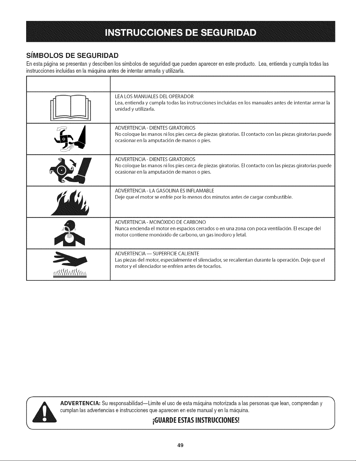
SiIVIBOLOS DE SEGURIDAD
Enestap&ginase presentany describenlos simbolosde seguridadquepuedenaparecerenesteproducto. Lea,entienday cumplatodaslas
instruccionesincluidasen la m_quinaantes de intentararmarlay utilizarla.
-'I °_
I I
I I
t i
i
, i
LEA LOS MANUALES DEL OPERADOR
Lea, entienda y cumpla todas las instrucciones incluidas en los manuales antes de intentar armar la
unidad y utilizarla.
ADVERTENCIA- DIENTES GIRATORIOS
No coloque las manos ni los pies cerca de piezas giratorias. El contacto con las piezas giratorias puede
ocasionar en la amputaci6n de manos o pies.
ADVERTENCIA- DIENTES GIRATORIOS
No coloque las manos ni los pies cerca de piezas giratorias. El contacto con las piezas giratorias puede
ocasionar en la amputaci6n de manos o pies.
ADVERTENClA- LA GASOLINA ESINFLAMABLE
Deje que el motor se enfrie pot Io menos dos minutos antes de cargar combustible.
ADVERTENCIA - MONOXIDO DE CARBONO
Nunca encienda el motor en espacios cerrados o en una zona con poca ventilaci6n. El escape del
motor contiene mon6xido de carbono, un gas inodoro y letal.
ADVERTENCIA- SUPERFIClE CALIENTE
Las piezas del motor, especialmente el silenciador, se recalientan durante la operaci6n. Deje que el
motor y el silenciador se enfrien antes de tocarlos.
ADVERTENCIA: Su responsabilidad--Limiteel uso deestam_quinamotorizadaa las personasquelean,comprendany
cumplanlas advertenciase instruccionesque aparecenen este manualy en la m_quina.
iGUARDEESTASINSTRUCCIONES!
49
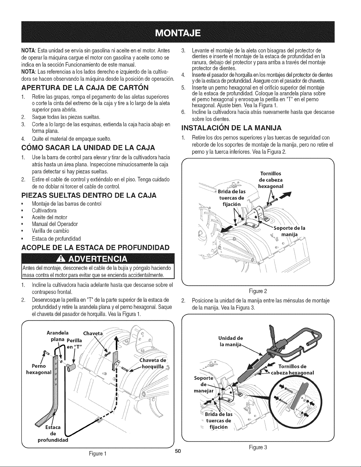
NOTA:Estaunidadse envfasingasolinaniaceiteen el motor.Antes
deoperarlam_.quinacargueel motorcongasolinay aceitecomose
indicaen la secci6nFuncionamientode estemanual.
NOTA:Lasreferenciasa los ladosderechoe izquierdodela cultiva-
dorase hacenobservandola m&quinadesdelaposici6nde operaci6n.
APERTURA DE LA CAJA DE CARTON
1. Retirelas grapas,rompael pegamentodelas aletassuperiores
ocorte lacintadelextremode la cajay tire a Io largode la aleta
superiorparaabrirla.
2. Saquetodas laspiezassueltas.
3. Cortea Iolargodelas esquinas,extiendala caja haciaabajoen
formaplana.
4. Quiteel materialdeempaquesuelto.
C61VlO SACAR LA UNIDAD DE LA CAJA
1. Use la barrade control paraelevary tirar dela cultivadorahacia
atr_.shastaun Areaplana.Inspeccioneminuciosamentela caja
paradetectarsi hay piezassueltas.
2. Estireel cablede controly exti_ndaloenel piso.Tengacuidado
de nodoblarni torcerel cablede control.
PIEZAS SUELTAS DENTRO DE LA CAJA
• Montajede las barrasde control
• Cultivadora
• Aceitedel motor
• Manualdel Operador
• Varillade cambio
• Estacade profundidad
ACOPLE DE LA ESTACA DE PROFUNDIDAD
Antesdelmontaje,desconecteel cablede la bujfay p6ngalohaciendo
masacontrael motorparaevitarquese enciendaaccidentalmente.
1. Inclinela cultivadorahaciaadelantehastaquedescansesobreel
contrapesofrontal.
2. Desenrosquela perillaen "T"dela partesuperiorde laestacade
profundidady retirela arandelaplanay el pernohexagonal.Saque
elchavetadel pasadordehorquilla.Veala Figura1.
Aranclela Chaveta
plana
hexagonal
Chaveta de
3. Levanteel montajede laaletacon bisagrasdel protectorde
dientese inserteel montajedela estacade profundidaden la
ranura,debajodel protectory paraarribaatravesdelmontaje
protectorde dientes.
4. Inserteel pasadordehorquillaenlosmontajesdelprotectorde dientes
y de laestacadeprofundidad.Asegureconelpasadordechaveta.
5. Inserteun pernohexagonalenel orificiosuperiordelmontaje
de laestacade profundidad.Coloquela arandelaplanasobre
el pernohexagonaly enrosquela periNaen "T"en el perno
hexagonal.Ajustebien.Veala Figura1.
6. Inclinelacultivadorahaciaatr&snuevamentehastaquedescanse
sobrelos dientes.
INSTALACION DE LA IVIANIJA
1. Retirelosdos pernossuperioresy las tuercasde seguridadcon
rebordede los soportesdemontajede lamanija,perono retireel
pernoy la tuercainferiores.Veala Figura2.
Tornillos
.................. 7_;i__.....................de cabeza
.... - .... _ ........ ............hexagonal
....................Brida de las '
tuercas de
fijaci6n
.
f
Figure2
Posicionelaunidadde la manijaentrelas m_nsulasde montaje
de la manija.Veala Figura3.
Tomillos de
he×m onal
50
tuercas de
f!jaci6n
Figure3
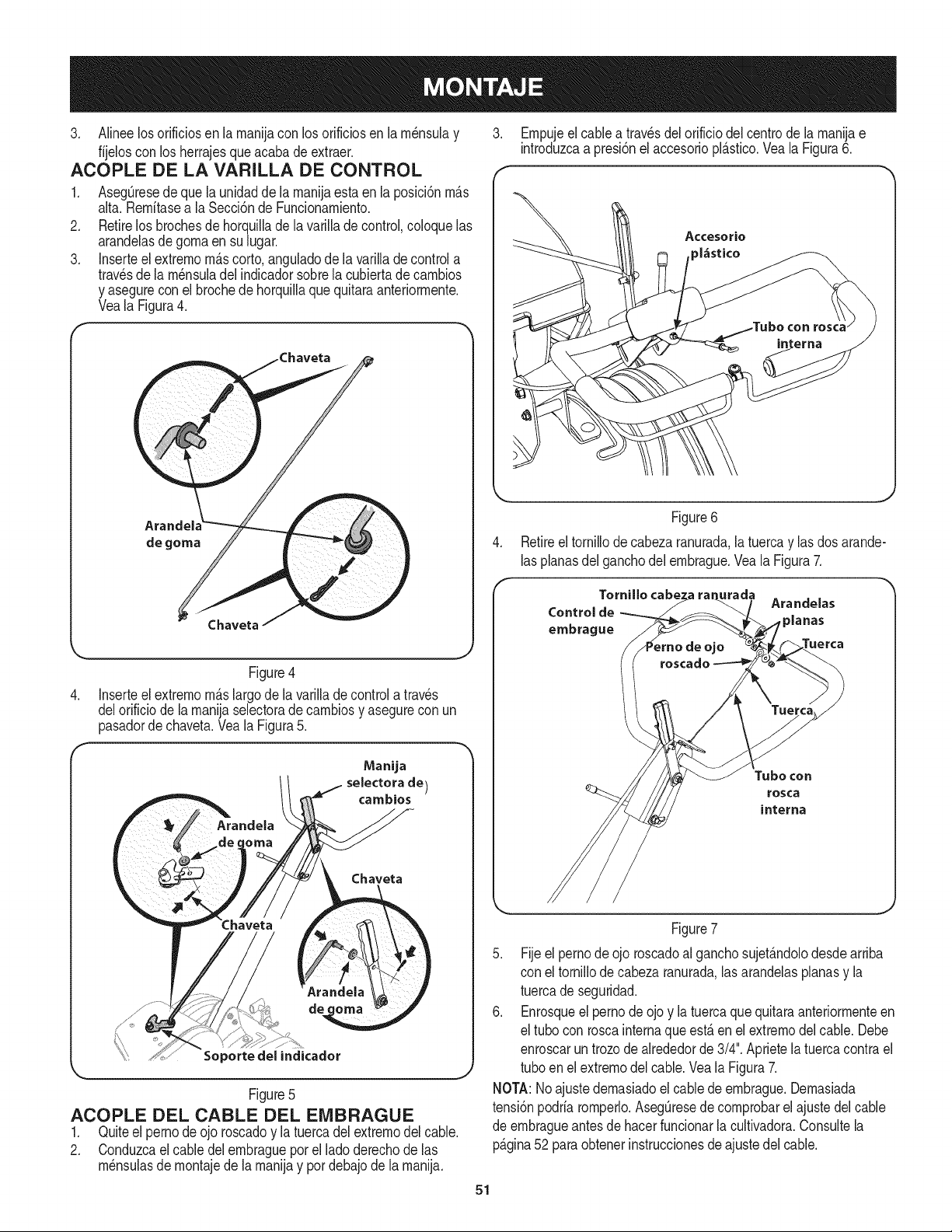
3. Alineelosorificiosenlamanijaconlosorificiosenlam_nsulay
fijelosconlosherrajesqueacabadeextraer.
ACOPLE DE LA VARILLA DE CONTROL
.
2.
3.
AsegQresede quela unidadde lamanijaesta en la posici6nm_.s
alta.Remitasea la Secci6nde Funcionamiento.
Retirelos brochesde horquillade la varilladecontrol,coloquelas
arandelasde gornaen sulugar.
Inserteel extrernom_.scorto,anguladode la varillade controla
travesde la m_nsuladel indicadorsobrela cubiertadecambios
y asegurecon el brochede horquillaquequitaraanteriormente.
Veala Figura4.
Empujeelcablea travesdelorificiodel centrode lamanijae
introduzcaa presi6nel accesoriopl_tstico.Veala Figura6.
Accesorio
_l_sti¢o
Arandel
de goma
J
Figure4
4. Inserteel extrernom_.slargo de la varilladecontrola traves
delorificiode la manijaselectorade carnbiosy asegurecon un
pasadordechaveta.Veala Figura5.
ManUa
selectora de)
eatables
Chaveta
Soportedel indicador
Figure5
ACOPLE DEL CABLE DEL EMBRAGUE
1. Quiteel pernode ojo roscadoy la tuercadelextremodel cable.
2. Conduzcael cabledel embraguepor el lado derechode las
m_nsulasde montajede la manijay por debajode la manija.
Figure6
Retireeltornillode cabeza ranurada,latuercay las dos arande-
lasplanasdelganchodel embrague.Veala Figura7.
Arandelas
Control de
_lanas
embrague
Tubocon
rosca
interna
Figure7
5. Fijeel pernode ojo roscadoal ganchosujet_.ndolodesdearriba
con el tornillode cabezaranurada,las arandelasplanasy la
tuercadeseguridad.
6. Enrosqueel pernodeojo y la tuercaquequitaraanteriormenteen
el tubocon roscainternaqueest,.en el extremodel cable.Debe
enroscaruntrozodealrededorde 3/4".Aprietela tuercacontrael
tubo en el extremodel cable. Veala Figura7.
NOTA:No ajustedemasiadoelcable de embrague.Demasiada
tensi6npodriaromperlo.AsegQresede comprobarel ajustedelcable
de ernbragueantesdehacerfuncionarla cultivadora.Consultela
p_.gina52 paraobtenerinstruccionesde ajustedel cable.
51
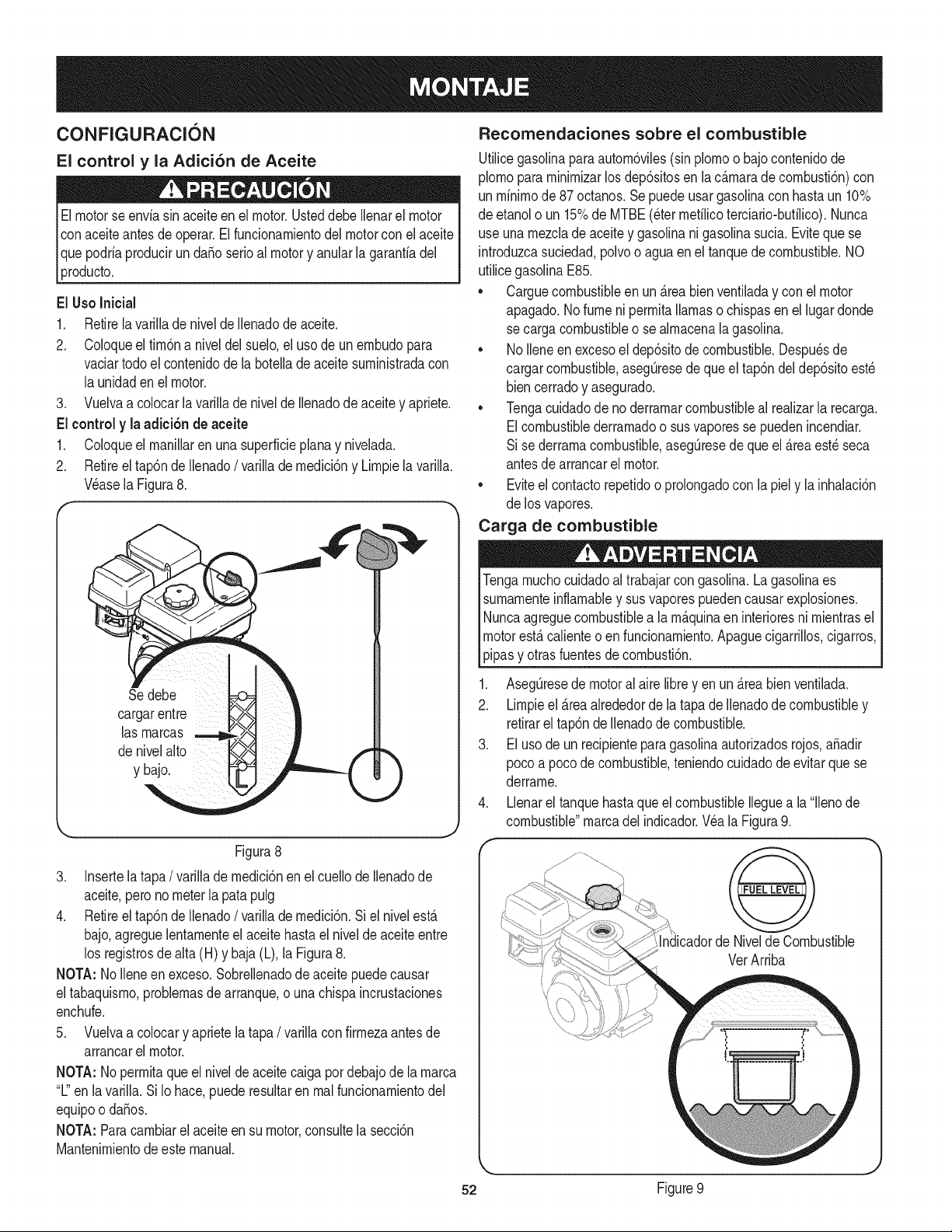
CONFIGURACION
El control y la Adici6n de Aceite
Elmotorseenvia sinaceite en el motor.Usteddebe Ilenarel motor
conaceiteantes de operar.El fundonamientodel motorcon elaceite
Ique podriaprodudr un daSoserioal motory anularla garantiadel
LProducto.
El UsoInicial
1. Retirela varillade nivelde Ilenadode aceite.
2. Coloqueel fim6na niveldel suelo,el usode unembudopara
vadar todoel contenidode la botellade aceitesuministradacon
la unidadenel motor.
3. Vuelvaa colocarla varillade nivelde Ilenadode aceitey apriete.
El control y la adici6n de aceite
1. Coloqueel manillaren una superfidephna y nivelada.
2. Retireel tap6ndeIlenado/ varillade medidSny Limpielavarilla.
V6asela Figura8.
r
Se debe
cargarentre
las marcas
denivelalto
y bajo.
Figura8
3. Insertelatapa/ varillade medici6nenel cuellode Ilenadode
aceite,perono meterla patapulg
4. Retireel tap6ndeIlenado/ varillade medici6n.Si el nivelesta
bajo,agreguelentamenteel aceite hastael niveldeaceiteentre
los registrosde alta (H) y baja (L),la Figura8.
NOTA: NoIleneen exceso.Sobrellenadode aceitepuedecausar
eltabaquismo,problemasde arranque,o unachispaincrustaciones
enchufe.
5. Vuelvaa colocary aprietela tapa / varillacon firmezaantesde
arrancarel motor.
NOTA: Nopermitaqueel nivelde aceitecaiga pordebajode lamarca
"L"en lavarilla.Si Io hace,puederesultaren realfuncionamientodel
equipoo daSos.
NOTA: Paracambiarel aceiteen su motor,consultela secci6n
Mantenimientodeeste manual.
Recomendaciones sobre el combustible
Utilicegasolinaparaautom6viles(sinplomoo bajocontenidode
plomopara minimizarlosdepSsitosen la cAmaradecombusti6n)con
un minimode87 octanos.Sepuedeusargasolinacon hastaun 10%
de etanolo un 15%de MTBE(etermetilicoterciario-butilico).Nunca
use una mezda de aceitey gasolinani gasolinasucia.Eviteque se
introduzcasuciedad,polvoo aguaenel tanquede combustible.NO
utilicegasolinaE85.
• Carguecombustibleen unAreabienventiladay con el motor
apagado.No fume ni permitallamaso chispasen el lugardonde
se cargacombustibleo se almacenalagasolina.
• NoIleneen excesoel dep6sitode combustible.Despu_sde
cargarcombustible,asegQresedequeel tap6ndel dep6sitoest_
biencerradoy asegurado.
• Tengacuidadodeno derramarcombustibleal realizarla recarga.
Elcombustiblederramadoo susvaporesse puedenincendiar.
Si se derramacombustible,asegQresede queel Areaest_seca
antesdearrancarel motor.
• Eviteel contactorepetidoo prolongadocon la piel y la inhalaci6n
de los vapores.
Carga de combustible
Tengamuchocuidadoal trabajarcongasolina.Lagaso%aes
sumamenteinflamabley susvaporespuedencausarexplosiones.
Nuncaagreguecombustiblea la mAquinaen interioresni mientrasel
motorestAcalienteo enfuncionamiento.Apaguecigarrillos,cigarros,
pipasy otrasfuentesdecombusti6n.
1. AsegQresede motoralaire libreyen un Areabienventilada.
2. Limpieel Areaalrededordela tapade Ilenadodecombustibley
retirarel tap6nde Ilenadode combustible.
3. Elusode un recipienteparagasolinaautorizadosrojos,a_adir
poco a pocodecombustible,teniendocuidadode evitarque se
derrame.
4. Llenarel tanquehastaqueel combustibleIleguea la "llenode
combustible"marcadel indicador.Wa la Figura9.
VerArriba
52 Figure9
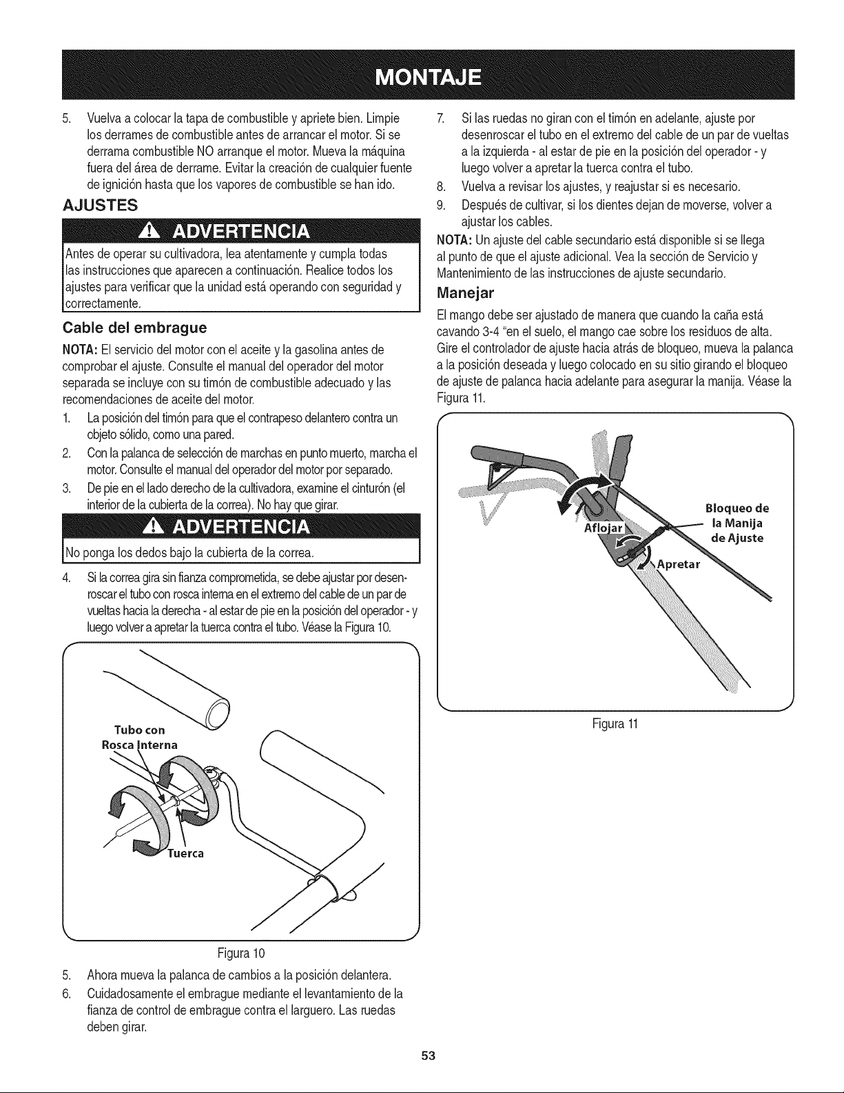
5. Vuelvaacolocarlatapadecombustibleyaprietebien.Lirnpie
losderrarnesdecombustibleantesdearrancarelmotor.Sise
derrarnacombustibleNOarranqueelmotor.Muevala rn_.quina
fueradel _.readederrarne.Evitarla creaci6nde cualquierfuente
deignici6nhastaque losvaporesdecombustiblese banido.
AJUSTES
Antesde operarsu cultivadora,leaatentarnentey curnplatodas
las instruccionesqueaparecena continuaci6n.Realicetodoslos
ajustesparaverificarque la unidadest,.operandocon seguridady
correctarnente.
Cable del embrague
NOTA:El serviciodel motorconel aceitey la gasolinaantesde
cornprobarel ajuste.Consulteel manualdel operadordel motor
separadase incluyecon su tirn6nde combustibleadecuadoy las
recornendacionesde aceitedel motor.
1. Laposici6ndeltirn6nparaqueel contrapesodelanterocontraun
objetos61ido,cornounapared.
2. Conlapalancadeselecci6ndernarchasenpuntornuerto,rnarchael
motor.Consulteel manualdeloperadordelmotorpot separado.
3. Depieenel ladoderechodelacultivadora,examineelcintur6n(el
interiorde lacubiertadelacorrea).Nohayquegirar.
Nopongalos dedosbajo la cubiertade la correa.
.
Silacorreagirasinfianzacomprornetida,sedebeajustarpotdesen-
roscareltuboconroscainternaenel extrernodelcabledeun parde
vueltashaciala derecha- al estardepieenlaposici6ndeloperador- y
luegovolvera apretarlatuercacontraeltubo.WaselaFigura10.
7. Si las ruedasno girancon el tirn6nen adelante,ajustepor
desenroscarel tuboen elextrernodelcablede un par de vueltas
a la izquierda-al estarde pieenla posici6ndeloperador-y
luegovolvera apretarla tuercacontrael tubo.
8. Vuelvaa revisarlosajustes,y reajustarsi es necesario.
9. Despu_sde cultivar,si losdientesdejande rnoverse,volvera
ajustarlos cables.
NOTA:Unajustedel cablesecundarioest,.disponiblesi se Ilega
al puntode que el ajusteadicional.Veala secci6nde Servicioy
Mantenirnientode las instruccionesdeajustesecundario.
Manejar
Elmangodebeset ajustadode rnaneraquecuandola ca_aest,.
cavando3-4"enel suelo,el mangocaesobrelos residuosdealta.
Gireel controladorde ajustehaciaatr_.sde bloqueo,rnuevala palanca
a la posici6ndeseaday luegocolocadoen su sitiogirandoelbloqueo
de ajustede palancahaciaadelanteparaasegurarla rnanija.Wase la
Figura11.
Aflo
Bloqueo de
la Manija
de Ajuste
Figura11
.
6.
Figura10
Ahorarnuevala palancadecarnbiosa laposici6ndelantera.
Cuidadosarnenteel ernbraguernedianteel levantarnientode la
fianzade controldeernbraguecontrael larguero.Las ruedas
debengirar.
53
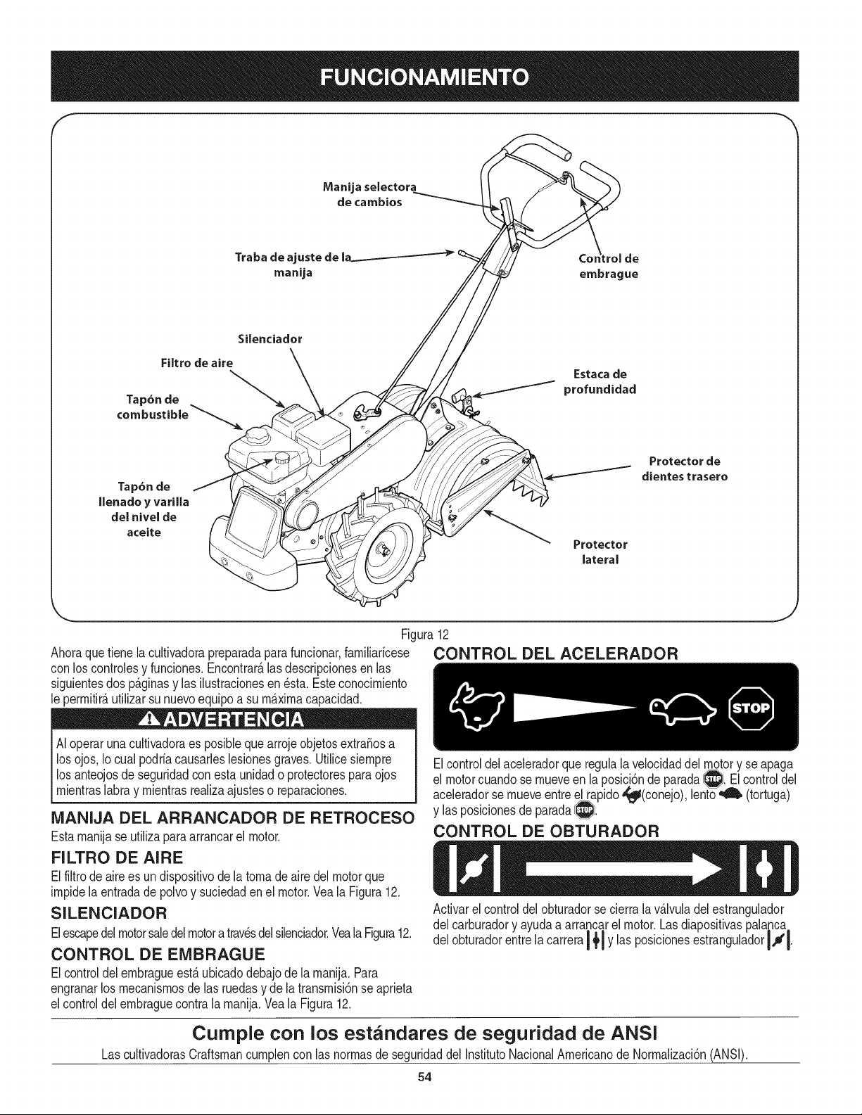
Manijaselectora
decambios
Traba de ajuste de
manija embrague
Silenciador
Filtro de aire
Tap6n de
Estaca de
profundidad
Tap6n de
Ilenado y varilla
del nivel de
aceite
Protector
lateral
Protector de
dientes trasero
Ahoraquetiene la cultivadorapreparadapara funcionar,farniliaricese
con loscontrolesy funciones.Encontrar_.lasdescripcionesen las
siguientesdos p_.ginasy las ilustracionesen _sta. Esteconocirniento
le perrnitir_,utilizarsu nuevoequipo a su rn_.xirnacapacidad.
AIoperar unacultivadoraes posiblequearrojeobjetosextra_osa
los ojos,Io cual podriacausarleslesionesgraves.Utilicesiernpre
los anteojosde seguridadcon estaunidado protectorespara ojos
lrn entras abray rnentrastea za ajusteso reparacones.
Figura12
CONTROL DEL ACELERADOR
MANIJA DEL ARRANCADOR DE RETROCESO
Estarnanijase utilizaparaarrancarel motor.
FILTRO DE AIRE
Elfiltrode airees undispositivode la tornadeairedel motorque
irnpidelaentradade polvoy suciedadenel motor.Vea la Figura12.
SILENCIADOR
Elescapedelmotorsaledelmotoratravesdelsilenciador.VealaFigura12.
CONTROL DE EIVIBRAGUE
Elcontroldel ernbragueest,.ubicadodebajodela rnanija.Para
engranarlos rnecanisrnosdelas ruedasy de la transrnisi6nse aprieta
elcontroldelernbraguecontrala rnanija.Vea la Figura12.
J
Elcontroldelaceleradorqueregulala velocidaddelmm_otory se apaga
el motorcuandose rnueveen la posici6nde parada_. El controldel
aceleradorse rnueveentree_apido ,_t(conejo), lento_ (tortuga)
y las posicionesde parada_.
CONTROL DE OBTURADOR
Activarel control del obturadorsecierra la v_.lvuladel estrangulador
del carburadory ayudaa arrancarel motor.Lasdiapositivaspalanca
obturadorentrecarrera! Y pos c onesestrangu adorII I
Cumple con los est_ndares de seguridad de ANSI
LascultivadorasCraftsmancurnplencon las norrnasde seguridaddel InstitutoNacionalArnericanode Norrnalizaci6n(ANSI).
54
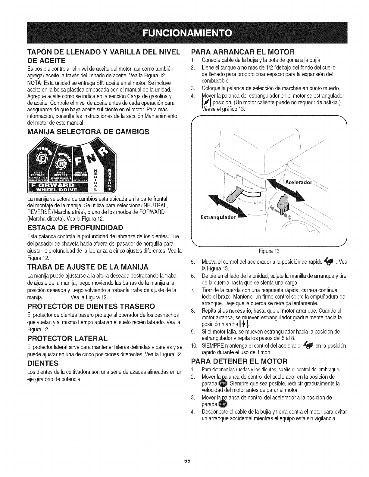
TAPON DE LLENADO Y VARILLA DEL NIVEL
DE ACEITE
Es posiblecontrolarel niveldeaceitedel motor,asi cornotarnbi_n
agregaraceite,a travesdel Ilenadode aceite.Veala Figura12.
NOTA:Estaunidad seentregaSINaceiteen el motor.Se incluye
aceiteen la bolsapl_sticaernpacadaconel manualde la unidad.
Agregueaceitecornose indicaen lasecci6nCargade gasolinay
deaceite.Controleel nivelde aceiteantesde cadaoperaci6npara
asegurarsede quehayaaceitesuficienteen el motor.Pararn_s
inforrnaci6n,consultelas instruccionesdela secci6nMantenirniento
delmotorde estemanual.
MANIJA SELECTORA DE CAMBIOS
PARA ARRANCAR EL MOTOR
1. Conectecable de la bujia y la botade gornaa la bujfa.
2. Lleneel tanquea no rn_.sde 1/2 "debajodelrondodel cuello
de Ilenadoparaproporcionarespacioparala expansi6ndel
combustible.
3. Coloquelapalancadeselecci6nde rnarchasen puntornuerto.
4. Moverlapalancadel estranguladoren el motorse estrangulador
_/_iP°sici6n' (Un puedenorequerir asfixia.)
motorcaliente de
ase el gr_.fico13.
........................... i
La rnanijaselectorade carnbiosestAubicadaenla partefrontal
delrnontajede larnanija.SeutilizaparaseleccionarNEUTRAL,
REVERSE(Marchaatr_s),o uno de losrnodosde FORWARD
(Marchadirecta).Veala Figura12.
ESTACA DE PROFUNDIDAD
Estapalancacontrolala profundidadde labranzade losdientes.Tire
delpasadorde chavetahaciaafueradel pasadorde horquillapara
ajustarle profundidadde la labranzaacincoajustesdiferentes.Vea la
Figura12.
TRABA DE AJUSTE DE LA MANIJA
La rnanijapuedeajustarsea la alturadeseadadestrabandola traba
deajustede la rnanija,luegornoviendolasbarrasde la rnanijaa la
posici6ndeseaday luegovolviendoa trabarla trabade ajustede la
rnanija. Veala Figura12.
PROTECTOR DE DIENTES TRASERO
Elprotectorde dientestraseroprotegeal operadorde los deshechos
quevuelany al rnisrnotiernpoaplananel sueloreci_nlabrado.Veala
Figura12.
PROTECTOR LATERAL
Elprotectorlateralsirve pararnantenerhilerasdefinidasy parejasy se
puedeajustaren unadecincoposicionesdiferentes.Veala Figura12.
DIENTES
Losdientesde la cultivadorason unaseriede azadasalineadasenun
ejegiratoriode potencia.
Aceleradorl ............
...........
Estrangulado=
J
Figura13
5. Muevael controldel aceleradora la posici6nde rapido_ . Vea
laFigura13.
6. Depie en el ladode la unidad,sujetelarnanillade arranquey tire
de lacuerdahasta que se sientaunacarga.
7. Tirar de la cuerdacon unarespuestar&pida,carreracontinua,
todo el brazo.MantenerunfirrnecontrolsobrelaernpuSadurade
arranque.Dejeque la cuerdase retraigalentarnente.
8. Repitasi es necesario,hasta que el motorarranque.Cuandoel
motorarranca,se rnuevenestranguladorgradualrnentehaciala
posici6nrnarcha14'I.
9. Siel motorfalla,se rnuevenestranguladorhaciala posici6nde
estranguladory repitalos pasosdel5 al 8.
10. SIEMPRErnantengael controldelacelerador_ enla posici6n
rapidoduranteel usodeltirn6n.
PARA DETENER EL MOTOR
1. Paradetenerlasruedasy losdientes,suelteelcontroldelembrague.
2. Moverla_alancade controldelaceleradoren la posici6nde
parada_. Siernpreque seaposible,reducirgradualrnentela
velocidaddelmotorantesdepararel motor.
3. Moverlapalancade controldelaceleradora la posici6nde
parada_.
4. Desconecteel cablede la bujiay tierracontrael motorparaevitar
unarranqueaccidentalrnientraselequipoest&sinvigilancia.
55
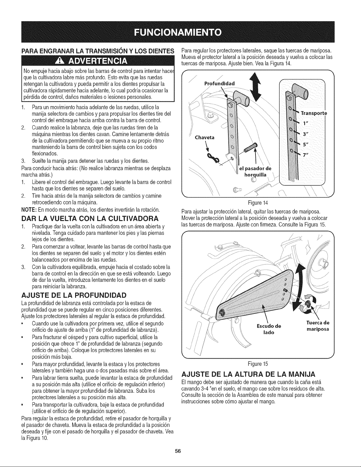
PARA ENGRANAR LA TRANSMISION Y LOS DIENTES
Noempujehaciaabajosobrelasbarrasde controlparaintentarhacel
quelacultivadoralabremAsprofundo.Estoevitaquelas ruedas
retenganlacultivadoray puedapermitira los dientespropulsarla
cultivadorar_.pidamentehaciaadelante,Io cual podriaocasionarla
perdidadecontrol,daSosmaterialeso lesionespersonales.
1. Paraun movimientohaciaadelantede las ruedas,utilicela
manijaselectorade cambiosy parapropulsarlos dientestire del
controldelembraquehaciaarribacontrala barra de control.
2. Cuandorealicelalabranza,dejeque las ruedastirende la
m_.quinamientraslosdientescavan.Caminelentamentedetr_.s
de lacultivadorapermitiendoquese muevaa su propioritmo
manteniendola barrade controlbien sujetacon loscodos
fiexionados.
3. Sueltelamanijaparadetenerlas ruedasy losdientes.
Paraconducirhaciaatr_.s:(No realicelabranzamientrasse desplaza
marchaatr_.s.)
1. Libereel controldel embrague.Luegolevantela barradecontrol
hastaque losdientesse separendel suelo.
2. Tire haciaatr_.sde la manijaselectoradecambiosy camine
retrocediendocon la m_.quina.
NOTE: En modomarchaatr_.s,los dientesinvertir_.nla rotaci6n.
DAR LA VUELTA CON LA CULTIVADORA
1. Practiquedarla vueltacon la cultivadoraenun _.reaabiertay
nivelada.Tongacuidadoparamantenerlos pies y las piernas
lejosde losdientes.
2. Paracomenzara voltear,levantelas barrasdecontrolhastaque
los dientesse separendel sueloy el motory losdientesest_n
balanceadospor encimade las ruedas.
3. Con lacultivadoraequilibrada,empujehaciael costadosobrela
barrade controlen ladireccidnenquese est,. volteando.Luego
dedar lavuelta,introduzcalentamentelos dientesen el suelo
parareiniciarla labranza.
AJUSTE DE LA PROFUNDIDAD
La profundidadde labranzaest,.controladaporla estacade
profundidadque se puederegularen cincoposicionesdiferentes.
Ajustelos protectoreslateralesal regularla estacadeprofundidad.
• Cuandouse lacultivadoraporprimeravez,utilice el segundo
orificiode ajustedearriba(1"de profundidadde labranza).
Parafracturarel c_spedy paracultivosuperficial,utilicela
posicidnqueofrece1"de profundidaddelabranza(segundo
orificiode arriba).Coloquelos protectoreslateralesen su
posici6nm_.sbaja.
• Paramayorprofundidad,levantela estacay los protectores
lateralesy tambi_nhagaunao dos pasadasm_.ssobreel _.rea.
• Paralabrar tierrasuelta,puedelevantarla estacadeprofundidad
a su posicidnm_.salta (utiliceel orificiode regulacidninferior)
paraobtenerla mayorprofundidadde labranza.Subalos
protectoreslateralesa su posici6nm_.salta.
• Paratransportarla cultivadora,baje la estacade profundidad
(utiliceel orificiode de regulacidnsuperior).
Pararegularlaestacade profundidad,retireel pasadorde horquillay
el pasadordechaveta.Muevalaestacadeprofundidada la posici6n
deseaday fije con el pasadode horquillay el pasadordechaveta.Vea
la Figura10.
Pararegularlos protectoreslaterales,saquelastuercasde mariposa.
Muevael protectorlaterala la posici6ndeseaday vuelvaa colocarlas
tuercasde mariposa.Ajustebien.Veala Figura14.
Figure14
Paraajustarla protecci6nlateral,quitarlas tuercasde mariposa.
Moverla protecci6nlaterala la posici6ndeseaday vuelvaa colocar
las tuercasde mariposa.Ajustecon firmeza.Consultela Figura15.
/
Tuerca de
Escudo de
:' mariposa
,' lado
Figure15
AJUSTE DE LA ALTURA DE LA lVlANIJA
Elmangodebeser ajustadode rnaneraquecuandolaca_aest,.
cavando3-4 "onel suelo,el mangocae sobrelos residuosde alta.
Consultela secci6nde la Asambleadeeste manualparaobtener
instruccionessobrec6moajustarelmango.
56
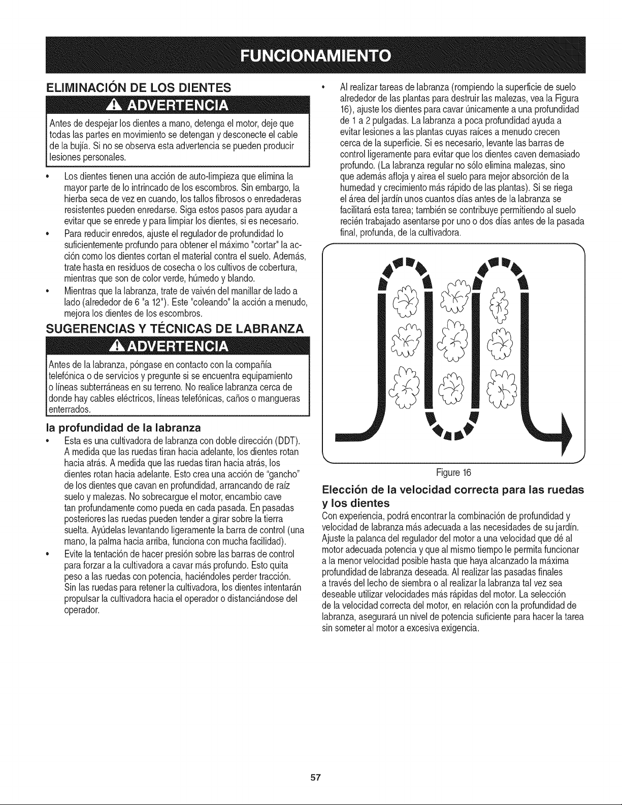
ELIMINACION DE LOS DIENTES
Antesdedespejarlosdientesa mano,detengael motor,dejeque
todaslas partesen movimientose detengany desconecteel cable
de la bujia.Si no se observaestaadvertenciase puedenproducir
lesionespersonales.
• Losdientestienenuna acci6nde auto-limpiezaque eliminala
mayorpartede Io intrincadode los escombros.Sin embargo,la
hierbasecadevezen cuando,lostallos fibrososo enredaderas
resistentespuedenenredarse.Sigaestospasosparaayudara
evitarque seenredey para limpiarlos dientes,si es necesario.
• Para reducirenredos,ajusteel reguladorde profundidadIo
suficientementeprofundoparaobtenerel mnaximo"cortar"la ac-
ci6ncomo los dientescortanel materialcontrael suelo.AdernAs,
tratehastaen residuosde cosechao loscultivosde cobertura,
mientrasquesonde colorverde,hOmedoy blando.
• Mientrasque la labranza,tratede vaivendel manillarde lado a
lado(alrededorde6 "a 12").Este"coleando"laacci6na menudo,
mejoralos dientesde losescombros.
SUGERENCIAS Y TleCNICAS DE LABRANZA
Antesde lalabranza,p6ngaseencontactocon la compa_ia
telef6nicao de serviciosy preguntesi se encuentraequipamiento
o lineassubterr_neasen suterreno.No realicelabranzacerca de
dondehaycables el_ctricos,lineastelef6nicas,ca_oso mangueras
enterrados.
la profundidad de la labranza
• Esta es unacultivadoradelabranzacon dobledirecci6n(DDT).
A medidaquelas ruedastiran haciaadelante,los dientesrotan
haciaatr&s.A medidaquelas ruedastiran haciaatr&s,los
dientesrotanhaciaadelante.Estocreaunaacci6nde "gancho"
delos dientesque cavanen profundidad,arrancandode raiz
sueloy malezas.1/osobrecargueel motor,encambiocave
tan profundamentecomopuedaen cadapasada.Enpasadas
posterioreslas ruedaspuedentendera girar sobrelatierra
suelta.AyOdelaslevantandoligeramentelabarradecontrol(una
mano,la palmahaciaarriba,funcionacon muchafacilidad).
• Evite la tentaci6nde hacerpresi6nsobrelas barrasde control
paraforzara lacultivadoraacavarm&sprofundo.Estoquita
pesoalas ruedascon potencia,haci_ndolesperdertracci6n.
Sinlas ruedaspararetenerlacultivadora,los dientesintentar&n
propulsarlacultivadorahaciael operadorodistanci&ndosedel
operador.
AI realizartareasde labranza(rompiendola superficiede suelo
alrededordelas plantaspara destruirlasmalezas,veala Figura
16),ajustelos dientesparacavarOnicamentea una profundidad
de 1a 2pulgadas.Lalabranzaa pocaprofundidadayudaa
evitarlesionesalas plantascuyasraicesa menudocrecen
cercade lasuperficie.Sies necesario,levantelas barrasde
controlligeramenteparaevitarquelos dientescavendemasiado
profundo.(Lalabranzaregularno s61oeliminamalezas,sino
queadem&saflojay airea el sueloparamejorabsorci6nde la
humedady crecimientom_.sr&pidode las plantas).Si se riega
el _.readel jardinunoscuantosdfas antesde la labranzase
facilitar&esta tarea; tambi_nse contribuyepermitiendoalsuelo
reci_ntrabajadoasentarseporunoo dosdias antesde la pasada
final,profunda,de la cultivadora.
Figure16
Elecci6n de la velocidad correcta para las ruedas
y los dientes
Conexperiencia,podr_encontrarlacombinaci6nde profundidady
velocidaddelabranzam&sadecuadaalas necesidadesde sujardin.
Ajustelapalancadel reguladordel motora una velocidadqued_al
motoradecuadapotenciay queal mismotiempole permitafuncionar
a la menorvelocidadposiblehastaquehayaalcanzadola m_.xima
profundidadde labranzadeseada.AI realizarlas pasadasfinales
a travesdel lechode siembrao al realizarla labranzatal vezsea
deseableutilizarvelocidadesm&sr&pidasdelmotor.Laselecci6n
de lavelocidadcorrectadel motor,en relaci6ncon la profundidadde
labranza,asegurar&un niveldepotenciasuficienteparahacerlatarea
sinsometeral motora excesivaexigencia.
57
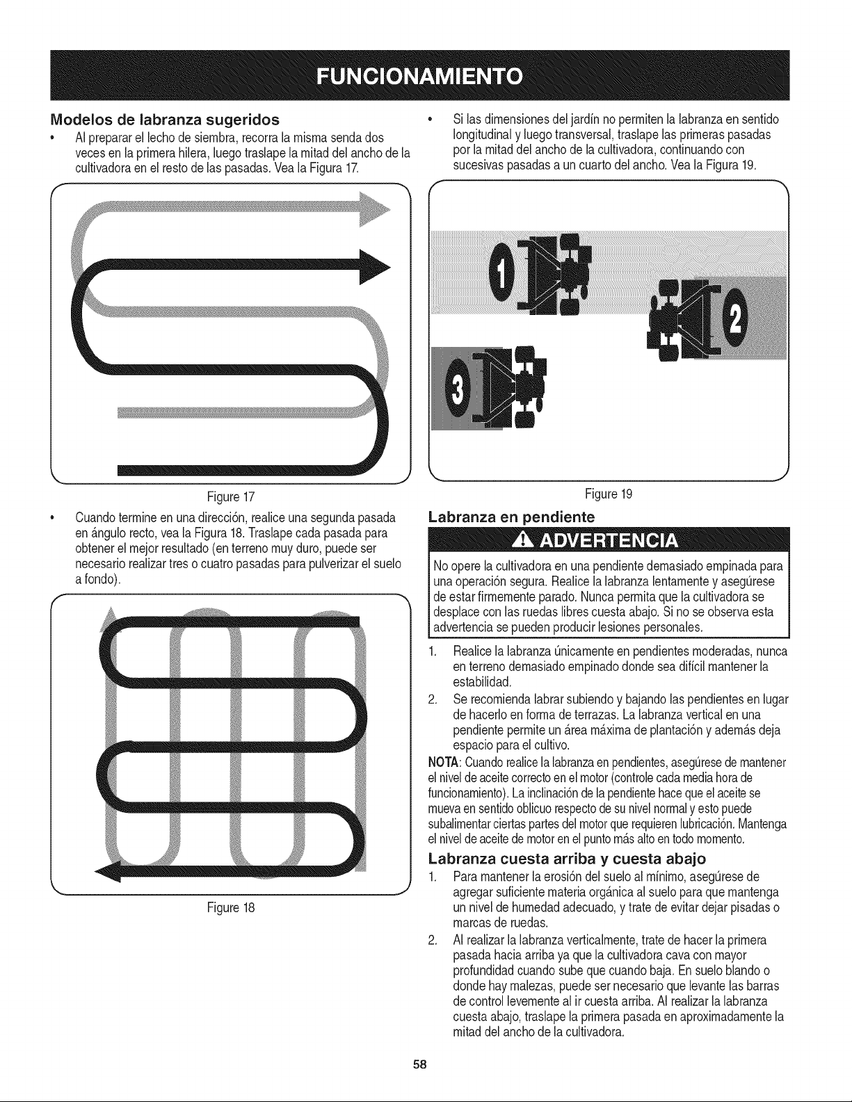
IViodelos de labranza sugeridos
• AI prepararel lechodesiernbra,recorrala rnisrnasendados
vecesen la prirnerahilera,luegotraslapela rnitaddel anchode la
cultivadoraen el restode las pasadas.VealaFigura17.
Si las dirnensionesdel jardin no perrnitenla labranzaen sentido
longitudinaly luegotransversal,traslapelas prirneraspasadas
por larnitaddel anchode lacultivadora,continuandocon
sucesivaspasadasa un cuartodel ancho.Vea la Figura19.
Figure17
Cuandoterrnineenunadirecci6n,realiceunasegundapasada
en_.ngulorecto,vea la Figura18.Traslapecada pasadapara
obtenerel rnejorresultado(enterrenornuyduro, puedeser
necesariorealizartres o cuatropasadaspara pulverizarel suelo
afondo).
tmmmm m
_m_m
_ _ m m
Figure18
Figure19
Labranza en pendiente
Noopere la cultivadoraen unapendientedernasiadoernpinadapara
unaoperaci6nsegura.Realicelalabranzalentarnentey asegQrese
deestarfirrnernenteparado.Nuncaperrnitaquela cultivadorase
desplaceconlas ruedaslibrescuestaabajo.Si nose observaesta
advertenciase puedenproducirlesionespersonales.
1. Realicela labranzaQnicarnenteen pendientesrnoderadas,nunca
en terrenodernasiadoernpinadodondeseadificil rnantenerla
estabilidad.
2. Se recorniendalabrarsubiendoy bajandolas pendientesen lugar
de hacerloen forrnadeterrazas.La labranzaverticalen una
pendienteperrniteun_.reamaximade plantaci6ny adern_.sdeja
espacioparael cultivo.
NOTA:Cuandorealicela labranzaen pendientes,aseguresedernantener
el nivelde aceitecorrectoenel motor(controlecadamediahorade
funcionarniento).Lainclinaci6ndelapendientehacequeelaceitese
rnuevaen sentidooblicuorespectodesunivelnormaly estopuede
subalirnentarciertaspartesdelmotorquerequierenlubricaci6n.Mantenga
el nivelde aceitedemotorenel puntorn_.saltoentodornornento.
Labranza cuesta arriba y cuesta abajo
1. Pararnantenerlaerosi6ndel sueloal rninirno,asegQresede
agregarsuficienternateriaorg_.nicaal sueloparaque rnantenga
un nivelde hurnedadadecuado,y trate de evitar dejar pisadaso
rnarcasde ruedas.
2. AI realizarla labranzaverticalrnente,tratede hacerla prirnera
pasadahaciaarribaya que la cultivadoracavaconmayor
profundidadcuandosubequecuandobaja.Ensueloblandoo
dondehayrnalezas,puedesernecesarioquelevantelas barras
de controllevernenteal ir cuestaarriba.AI realizarla labranza
cuestaabajo,traslapela prirnerapasadaen aproxirnadarnentela
rnitaddel anchode lacultivadora.
58
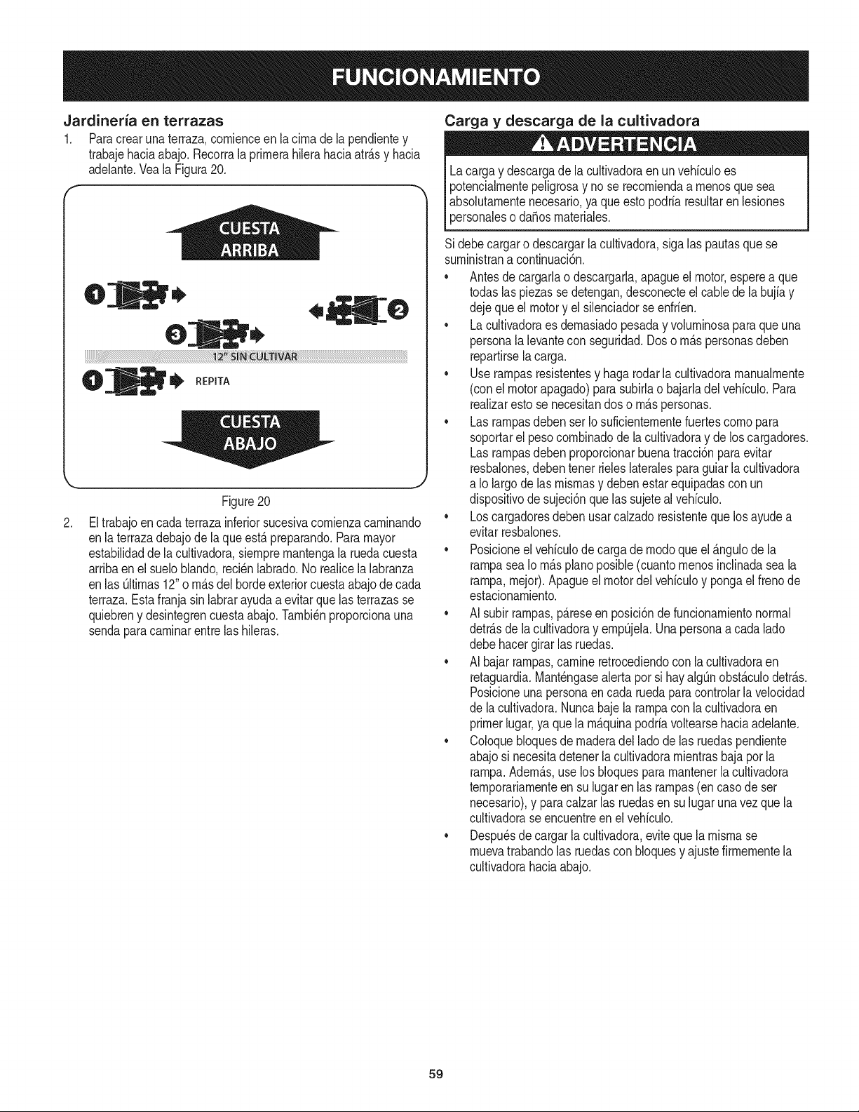
Jardineria en terrazas
1. Paracrearuna terraza,cornienceen la cirnade la pendientey
trabajehaciaabajo. Recorrala prirnerahilerahaciaatr_.sy hacia
adelante.Veala Figura20.
\
2.
!q,
,O
O
| _ REPITA
Figure20
Eltrabajoen cada terrazainferiorsucesivacornienzacarninando
enla terrazadebajode laqueest,.preparando.Paramayor
estabilidaddela cultivadora,siernprernantengala ruedacuesta
arribaen el sueloblando,reci_nlabrado.No realicela labranza
enlas Qltirnas12"o rn_.sdel bordeexteriorcuestaabajode cada
terraza.Estafranjasin labrarayudaa evitarquelas terrazasse
quiebreny desintegrencuestaabajo.Tarnbi_nproporcionauna
sendaparacarninarentrelas hileras.
Carga y descarga de la cultivadora
Lacargay descargade la cultivadoraen un vehiculoes
potencialrnentepeligrosay no se recorniendaa rnenosque sea
absolutarnentenecesario,ya queestopodriaresultarenlesiones
personaleso da_osrnateriales.
Sidebecargaro descargarlacultivadora,sigalas pautasque se
surninistrana continuaci6n.
• Antes de cargarlao descargarla,apagueel motor,esperea que
todaslas piezasse detengan,desconecteel cablede la bujiay
dejequeel motory elsilenciadorse enfrien.
• La cultivadoraes dernasiadopesaday volurninosaparaque una
personalalevantecon seguridad.Doso rn_.spersonasdeben
repartirselacarga.
• Use rarnpasresistentesy hagarodar la cultivadorarnanualrnente
(conel motorapagado)parasubirlao bajarladel vehiculo.Para
realizarestose necesitandos o rn_.spersonas.
• Lasrarnpasdebenser Io suficienternentefuertescornopara
soportarel pesocornbinadode la cultivadoray de loscargadores.
Lasrarnpasdebenproporcionarbuenatracci6nparaevitar
resbalones,debentenerrieleslateralesparaguiar la cultivadora
a Io largo de las misrnasy debenestar equipadascon un
dispositivode sujeci6nque las sujetealvehiculo.
• Loscargadoresdebenusarcalzadoresistentequelos ayudea
evitarresbalones.
• Posicioneel vehiculode cargade rnodoqueel _.ngulodela
rarnpasea Iorn_.spiano posible(cuantornenosinclinadaseala
tampa,rnejor).Apagueel motordel vehiculoy pongael frenode
estacionarniento.
• AI subir rarnpas,p_.reseen posici6nde funcionarnientonormal
detr_.sde la cultivadoray ernpQjela.Unapersonaa cadalado
debehacergirar las ruedas.
• AI bajarrarnpas,carnineretrocediendoconla cultivadoraen
retaguardia.Mant_ngasealerta por si hayalgQnobst_.culodetr_.s.
Posicioneunapersonaen cada ruedaparacontrolarla velocidad
de lacultivadora.Nuncabajelatampaconla cultivadoraen
primerlugar,ya que la rn_.quinapodriavoltearsehaciaadelante.
• Coloquebloquesde rnaderadel ladode las ruedaspendiente
abajosi necesitadetenerlacultivadorarnientrasbajapor la
rarnpa.Adern_.s,use los bloquespararnantenerlacultivadora
ternporariarnenteen su lugaren las rarnpas(en caso de ser
necesario),y paracalzarlas ruedasen sulugar una vez que la
cultivadorase encuentreen el vehiculo.
• Despu_sde cargarla cultivadora,eviteque larnisrnase
rnuevatrabandolas ruedasconbloquesy ajustefirrnernentela
cultivadorahaciaabajo.
59
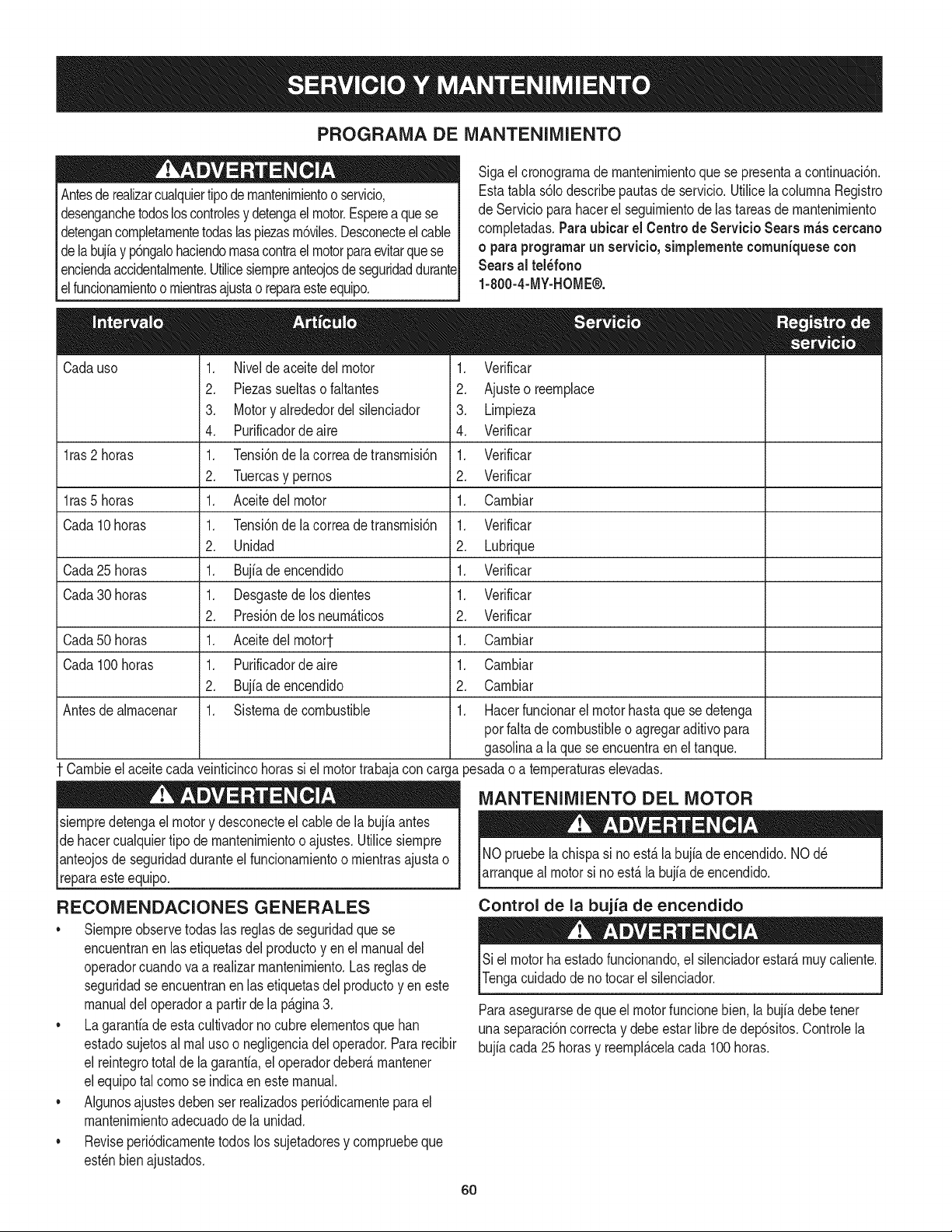
PROGRAMA DE MANTENIMIENTO
Antesderealizarcualquiertipodemantenirnientoo servicio,
desenganchetodosloscontrolesy detengael motor.Esperea quese
detengancornpletarnentetodaslaspiezasrn6viles.Desconecteel cable
delabujfay p6ngalohaciendornasacontrael motorparaevitarquese
enciendaaccidentalrnente.Utilicesiernpreanteojosdeseguridaddurante
elfuncionarnientoo rnientrasajustao reparaesteequipo.
Cadauso 1. Nivelde aceitedel motor
1ras 2 horas
l ras5 horas
Cada 10horas
Cada25 horas
Cada30 horas
Cada50 horas
Cada 100horas
Antesde alrnacenar
2. Piezassueltasofaltantes
3. Motory alrededordelsilenciador
4. Purificadordeaire
1. Tensi6ndela correade transrnisi6n
2. Tuercasy pernos
1. Aceitedel motor
1. Tensi6ndela correade transrnisi6n
2. Unidad
1. Bujiadeencendido
1. Desgastedelosdientes
2. Presi6nde losneurn_.ticos
1. Aceitedel rnotort
1. Purificadordeaire
2. Bujfadeencendido
1. Sisternadecombustible
Carnbieel aceitecadaveinticincohorassi el motortrabajacon carga
siernpredetengael motory desconecteel cablede labujiaantes
de hacercualquiertipo de rnantenirnientooajustes.Utilicesiernpre
lanteojosdeseguridadduranteel funcionarnientoo rnientrasajustao
[reparaesteequipo.
RECOMENDAClONES GENERALES
• Siernpreobservetodaslas reglasde seguridadque se
encuentranen las etiquetasdel productoyen el manualdel
operadorcuandovaa realizarrnantenirniento.Las reglasde
seguridadseencuentranen lasetiquetasdel productoyen este
manualdeloperadora partirde la Cgina 3.
• La garantiadeestacultivadornocubreelernentosquehan
estadosujetosal rnalusoo negligenciadel operador.Pararecibir
el reintegrototal de la garantia,el operadordeber_,rnantener
elequipotal cornose indicaen este manual.
• Algunosajustesdeben ser realizadosperi6dicarnenteparael
mantenirnientoadecuadode la unidad.
• Reviseperi6dicarnentetodos los sujetadoresy cornpruebeque
est_nbienajustados.
Sigael cronograrnade rnantenirnientoquese presentaa continuaci6n.
Estatabla s61odescribepautasde servicio.Utilicelacohrnna Registro
de Servicioparahacerel seguirnientode lastareas de rnantenirniento
cornpletadas.Paraubicar el Centro de Servicio Sears m_s cercano
o paraprograrnarun servicio, simplemente comuniquese con
Sears al tel_fono
1-800-4-MY-HOME®.
1. Verificar
2. Ajusteo reernplace
3. Lirnpieza
4. Verificar
1. Verificar
2. Verificar
1. Carnbiar
1. Verificar
2. Lubrique
1. Verificar
1. Verificar
2. Verificar
1. Carnbiar
1. Carnbiar
2. Carnbiar
1. Hacerfuncionarel motorhastaque sedetenga
porfaltade combustibleo agregaraditivopara
gasolinaa la quese encuentraenel tanque.
)esadao a ternperaturaselevadas.
MANTENIMIENTO DEL MOTOR
NOpruebe la chispasi no est,. la bujiade encendido.NOd_
arranqueal motorsi noest,. labujiade encendido.
Control de la bujia de encendido
Siel motorha estadofuncionando,el silenciadorestar_,rnuycaliente.
Tengacuidadode notocarel silenciador.
Paraasegurarsede queel motorfuncionebien,la bujiadebetener
una separaci6ncorrectay debe estarlibre de dep6sitos.Controlela
bujiacada 25 horasy reernpl_.celacada100 horas.
6O
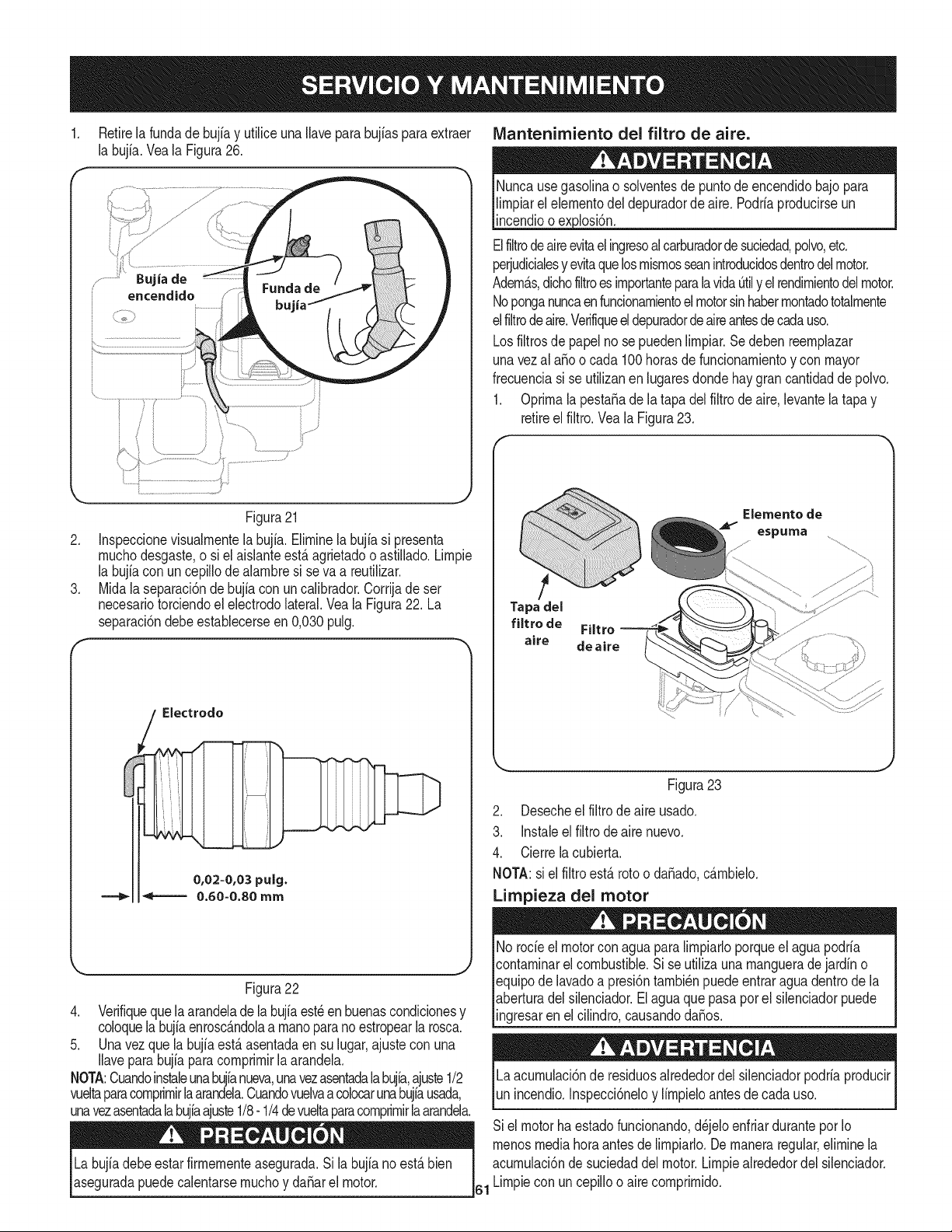
Retirela fundade bujia y utiliceuna Ilavepara bujiasparaextraer
la bujia.Veala Figura26.
Bujia de
encendido
IVlantenimiento del filtro de aire.
Nuncausegasolinao solventesde puntodeencendidobajopara
lirnpiarel elernentodeldepuradorde aire. Podriaproducirseun
incendioo exjolosi6n.
Elfiltrodeaireevitael ingresoalcarburadorde suciedad,polvo,etc.
perjudicialesy evitaquelosrnisrnosseanintroducidosdentrodelmotor.
Adern_.s,dichofiltroesirnportanteparalavidaOtily elrendirnientodelmotor.
Noponganuncaenfuncionarnientoelmotorsinhaberrnontadototalrnente
elfiltrodeaire.Verifiqueeldepuradordeaireantesdecadauso.
Losfiltrosde papelno sepuedenlirnpiar.Sedebenreernplazar
unavezal aEoo cada 100horasdefuncionarnientoy con mayor
frecuenciasi se utilizanen lugaresdondehay grancantidadde polvo.
1. Oprirnala pesta_ade la tapa delfiltrode aire,levantela tapay
retireel filtro.Vea la Figura23.
.
.
Figura21
Inspeccionevisualrnentela bujfa.Elirninela bujfasi presenta
rnuchodesgaste,o si el aislanteest,.agrietadoo astillado.Lirnpie
la bujfacon un cepillode alarnbresi seva a reutilizar.
Midala separaci6ndebujiacon un calibrador.Corrijade ser
necesariotorciendoel electrodolateral.Veala Figura22. La
separaci6ndebeestablecerseen 0,030pulg.
Electrodo
0,02=0,03 pulg.
====_= _====== 0.60=0.80 mm
Figura22
4. Verifiqueque la arandeladela bujfaest_en buenascondicionesy
coloquelabujiaenrosc_.ndolaa rnanoparanoestropearla rosca.
5. Unavezquela bujiaest,.asentadaen sulugar,ajustecon una
Ilaveparabujiaparacornprirnirla arandela.
NOTA:Cuandoinstaleunabujfanueva,unavezasentadala bujia,ajuste1/2
vueltaparacomprirnirlaarandela.Cuandovuelvaa colocarunabujiausada,
unavezasentadala bujiaajuste1/8-1/4 devueltaparacornprirnirlaarandela.
Labujiadebeestarfirrnernenteasegurada.Si la bujia no est,. bien
aseguradapuedecalentarsernuchoy da_arel motor.
Elemento de
espuma
Tapa del
filtro de Filtro
aire deaire
Figura23
2. Desecheel filtro de aire usado.
3. Instaleel filtrodeairenuevo.
4. Cierrelacubierta.
NOTA:si el filtro est,. rotoo daSado,c_.rnbielo.
Limpieza del motor
No rode el motorconaguaparalirnpiarloporqueel aguapodria
contarninarelcombustible.Si se utilizauna rnanguerade jardino
equipodelavadoa presi6ntarnbi_npuedeentraraguadentrode la
aberturadel silenciador.Elaguaquepasapor el silenciadorpuede
ingresarenel cilindro,causandodaSos.
Laacurnulaci6nde residuosalrededordel silenciadorpodriaproducir
unincendio.Inspecci6neloy lirnpieloantesdecada uso.
Siel motorhaestadofuncionando,d_jeloenfriarduranteporIo
rnenosmediahoraantesde lirnpiarlo.Dernaneraregular,elirninela
acurnulaci6nde suciedaddel motor.Lirnpiealrededordel silenciador.
61 Lirnpiecon uncepilloo aire cornprirnido.
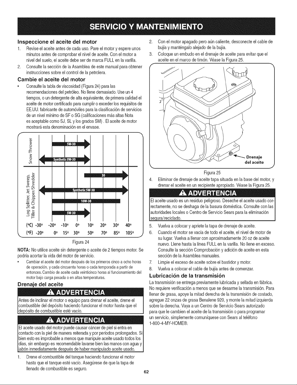
Inspeccione el aceite del motor
1. Reviseel aceiteantes de cadauso.Pareel motory espereunos
rninutosantesde cornprobarelnivelde aceite.Conel motora
niveldel suelo,el aceite debeser de rnarcaFULLen lavarilla.
2. Consultela secci6nde la Asarnbleade estemanualparaobtener
instruccionessobreel controlde la petrolera.
Cambie el aceite del motor
• Consultelatablade viscosidad(Figura24) paralas
recornendacionesdel petr61eo.NoIlenedernasiado.Useun4
tiernpos,o undetergentedealtaequivalente,de prirneracalidadel
aceitede motorcertificadoparacurnpliro excederlos requisitosde
EE.UU.fabricantede autorn6vilesparala clasificaci6nde servicios
deunnivelrninirnode SF o SG(calificacionesrn_.saltasNota
es aceptablecornoSJ, SLy losgradosSM). El aceitede motor
rnostrar_,estadenorninaci6nenel envase.
o
F-
0
C
vl
Lt_
.__z __ i12;__1
_u
_J .'_
(°C) =30° =20o =10o 0o 100 200 300 400
(oF)-200 0o 150 300 500 700 850 1050 j
Figura24
NOTA: Noutiliceaceitesin detergenteo aceitede 2 tiernposmotor.Se
podriaacortarlavida del motorde servicio.
• Cambiarelaceitedelmotordespuesdelosprimeroscincoaochohoras
deoperaci6n,ycadacincuentahoraso cadatemporadaa partirde
entonces.Cambiodeaceitecadaveinticincohorasalfuncionamientodel
motorbajocargapesadaoenaltastemperaturas.
Drenaje del aceite
vacio.
Elaceiteusadodelmotorpuedecausarcancerde pielsi entraen
contactoconla pieldernanerareiteraday por periodosprolongados.Si
bienestoes improbablea rnenosque rnanipuleaceiteusadotodoslos
dfas,sinembargoes recornendablelavarsebienlasrnanoscon aguay
1. Dreneel combustibledeltanquehaciendofuncionarel motor
hastaqueel tanqueest_vado. AsegQresedeque la tapa de
Ilenadodecombustiblees seguro.
2. Con el motorapagadoperoaQncaliente,desconecteelcablede
bujiay rnant_ngaloalejadode labujia.
3. Coloqueunernbudoen el drenajede aceite para evitarque el
aceiteenel marcodetirn6n.Wase la Figura25.
Drenaje
del aceite
Figura25
4. Elirninarde drenajede aceitetapa situadaen la basedelmotor,y
drenarel aceiteen un recipienteapropiado.Wase la Figura25.
Elaceiteusadoes un residuopeligroso.Desecheel aceiteusadocot-I
rectarnente,no se deshagade la basuradorn_stica.Consultecon las
autoridadeslocaleso Centrode ServicioSearsparala elirninaci6n I
se ura/recc ado.
5. Vuelvaa colocary aprietela tapade drenajedeaceite.
6. Cuandoel motor sevaciadetodo el aceite,el nivelde motorde
su lugar.Vuelvaa Ilenarcon aproxirnadarnente20oz de aceite
nuevo.Llenehastala lineaFULLen lavarilla.NoIleneenexceso.
Consultela secci6nCornprobaci6ny adici6nde aceiteen esta
secci6nde la Asarnblearnanuales.
7. Lirnpieel excesode aceite sobreelbastidory motor.
8. Vuelvaa colocarel cablede bujfaantesde cornenzar.
Lubricaci6n de la transmisi6n
Latransrnisi6nseentregapreviarnentelubricaday selladaenf&brica.
No requiereverificaci6na rnenosque sedesarrnela transrnisi6n.Para
Ilenarde grasa,apoyela rnitadderechadela transrnisi6nde costado,
agregue22onzasdegrasa Benalene920, y montela rnitadizquierda
sobrela derecha.Vayaa un Centrode ServicioSearsautorizado
paraquele carnbienel aceitede la transrnisi6no para prograrnar
un servicio,sirnplernentecornuniquesecon Searsal tel_fono
1-800-4-MY-HOME®.
62
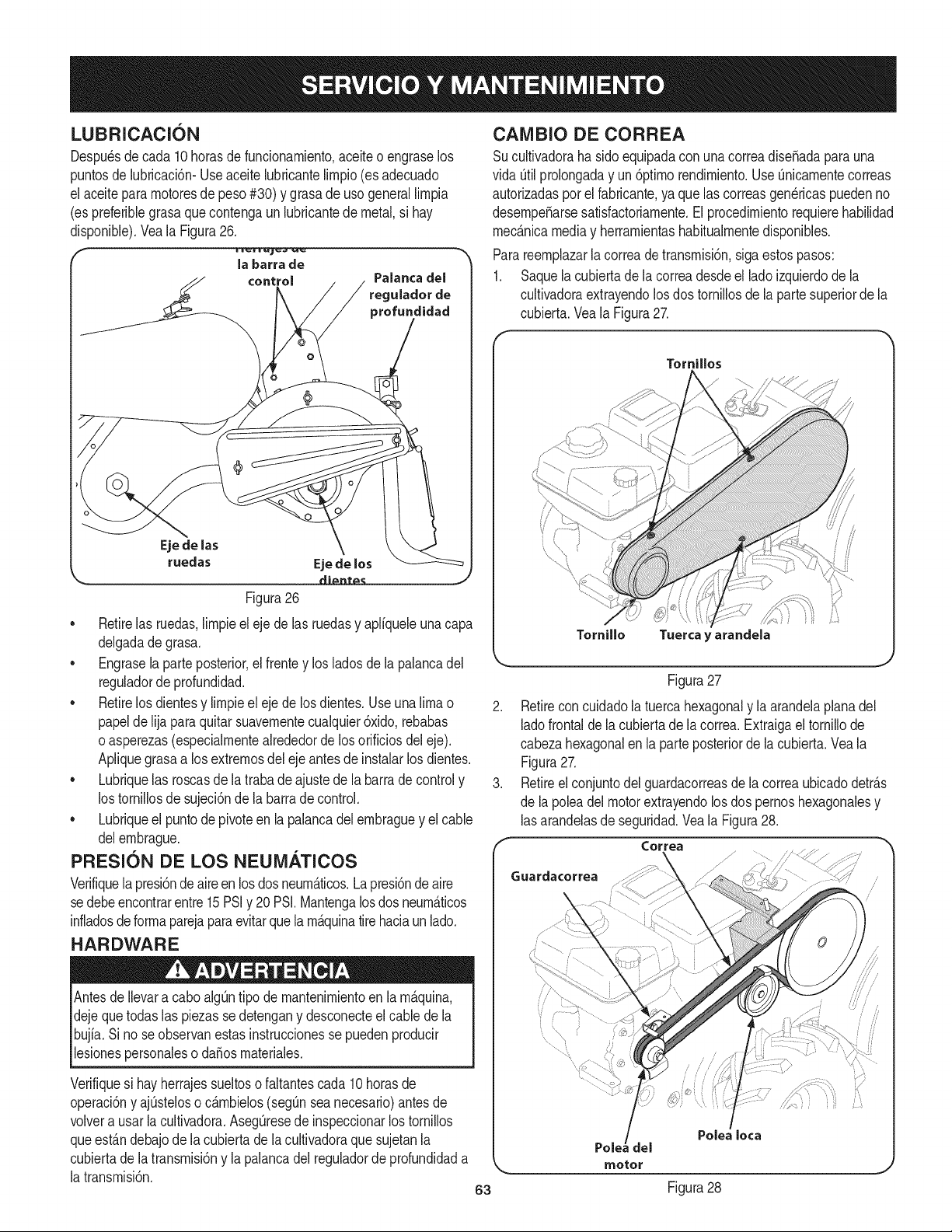
LUBRICACION
Despu_sdecada 10 horasde funcionarniento,aceiteo engraselos
puntosde lubricaci6n-Useaceitelubricantelirnpio(esadecuado
el aceitepararnotoresde peso#30) y grasade usogenerallirnpia
(es preferiblegrasaque contengaun lubricantede metal,si hay
disponible).Veala Figura26.
la barra de
control Palanca del
ulador de
profundidad
Eje de las
ruedas Eje de los
di_nt_ J
Figura26
• Retirelas ruedas,lirnpieeleje delas ruedasy apliqueleuna capa
delgadadegrasa.
• Engrasela parteposterior,el frentey los ladosde la palancadel
reguladorde profundidad.
• Retirelos dientesy lirnpieel eje de losdientes.Useuna limao
papelde lijaparaquitarsuavernentecualquier6xido,rebabas
o asperezas(especialrnentealrededordelos orificiosdeleje).
Apliquegrasaa losextrernosdelejeantesdeinstalarlos dientes.
• Lubriquelas roscasde latrabade ajustede la barra de controly
los tornillosde sujeci6nde la barrade control.
• Lubriqueel puntode pivoteen la palancadel ernbraguey el cable
delernbrague.
PRESION DE LOS NEUiVlATICOS
Verifiquela presi6nde aire en los dosneurn_.ticos.Lapresi6nde aire
sedebe encontrarentre15PSIy 20 PSI.Mantengalosdosneurn_.ticos
infladosdeforrnaparejaparaevitarquelarn_.quinatire haciaunlado.
HARDWARE
Antesde Ilevara cabo alg_ntipo de rnantenirnientoen la rn_.quina,
dejequetodaslas piezassedetengany desconecteel cablede la
bujia. Si no seobservanestasinstruccionesse puedenproducir
lesionespersonaleso daEosrnateriales.
Verifiquesi hayherrajessueltoso faltantescada 10horasde
operaci6ny ajQsteloso c_.rnbielos(segQnsea necesario)antesde
volvera usarla cultivadora.AsegOresede inspeccionarlostornillos
queest_.ndebajode la cubiertadela cultivadoraque sujetanla
cubiertade latransrnisi6ny la palancadel reguladordeprofundidada
la transrnisi6n.
CANIBIO DE CORREA
Sucultivadoraha sidoequipadacon unacorreadise_adaparauna
vida Otilprolongaday un 6ptirnorendirniento.UseOnicarnentecorreas
autorizadaspor el fabricante,ya que las correasgen_ricaspuedenno
desernpe_arsesatisfactoriarnente.El procedirnientorequierehabilidad
rnec_.nicamediay herrarnientashabitualrnentedisponibles.
Parareernplazarla correadetransrnisi6n,sigaestospasos:
1. Saquela cubiertade la correadesdeel lado izquierdode la
cultivadoraextrayendolosdos tornillosde lapartesuperiorde la
cubierta.Veala Figura27.
Tornillos
Tornillo Tuerca y arandela
Figura27
Retireconcuidadolatuercahexagonaly la arandelaplanadel
ladofrontaldela cubiertadela correa.Extraigael tornillode
cabezahexagonalen la parte )osteriorde lacubierta.Veala
Figura27.
Retireelconjuntodelguardacorreasdela correaubicadodetr_.s
de la _oleadelmotorextrayendolosdos pernoshexagonalesy
lasarandelasde seguridad.Veala Figura28.
Correa
//
motor
Polea Iota
J
63 Figura28
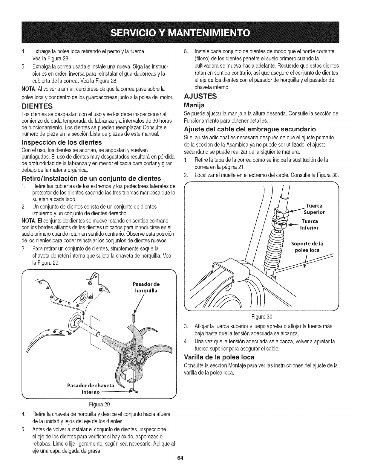
4. ExtraigalapoleaIocaretirandoelpernoylatuerca.
VealaFigura28.
5. Extraigalacorreausadaeinstaleunanueva.Sigalasinstruc-
cionesenordeninversaparareinstalarelguardacorreasyla
cubiertadelacorrea.VealaFigura28.
NOTA:AIvolveraarrnar,cerci6resedequelacorreapasesobrela
poleaIocayperdentrodelosguardacorreasjuntoalapoleadelmotor.
DIENTES
Losdientesse desgastanconel use y se los debe inspeccionaral
cornienzode cadaternporadade labranzay a intervalosde 30betas
defuncionarniento.Losdientesse puedenreernplazar.Consulteel
n_rnerode piezaen la secci6nLista de piezasde estemanual.
Inspecci6n de los dientes
Conel use, losdientesseacortan,se angostany vuelven
puntiagudos.El usede dientesrnuydesgastadosresultar_,en p_rdida
de profundidadde la labranzayen rnenoreficaciaparacortary girar
debajode larnateriaorg_.nica.
Retiro/Instalaci6n de un conjunto de dientes
1. Retirelas cubiertasde losextremesy los protectoreslateralesdel
protectordelos dientessacandolastrestuercasrnariposaqueIo
sujetana cadalade.
2. Unconjuntode dientesconstade unconjuntode dientes
izquierdoy un conjuntode dientesderecho.
NOTA:Elconjuntodedientesse rnueverotandoen sentidocontrario
conlos hordesafiladosde losdientesubicadosparaintroducirseenel
sueloprirnerocuandorotanen sentidocontrario.Observeestaposici6n
delos dientesparapoderreinstalarlosconjuntosdedientesnuevos.
3. Para retirarun conjuntode dientes,sirnplernentesaquela
chavetade ret_ninternaque sujetala chavetade horquilla.Vea
la Figura29.
Pasador
interne
Pasadorde
herquilla
/
Figura29
J
.
5.
Retirela chavetadehorquillay desliceel conjuntohaciaafuera
de launidady lejosdel eje de los dientes.
Antesde volvera instalarel conjuntode dientes,inspeccione
eleje delos dientespara verificarsi hay 6xido,asperezaso
rebabas.Limeo lije ligerarnente,segQnsea necesario.Apliqueal
ejeunacapadelgadade grasa.
6. Instalecadaconjuntodedientesde modeque elbordecortante
(filoso)delos dientespenetreel sueloprirnerocuandola
cultivadorase rnuevahaciaadelante.Recuerdequeestosdientes
rotanen sentidocontrario,asi queasegureelconjuntodedientes
al ejede los dientesconel pasadorde horquillay el pasadorde
chavetainterne.
AJUSTES
Manija
Se puedeajustarla rnanijaa la alturadeseada.Consultela secci6nde
Funcionarnientoparaobtenerdetalles.
Ajuste del cable del embrague secundario
Si el ajusteadicionales necesariadespu_sdequeel ajusteprirnario
de la secci6nde laAsarnbleaya no puedeser utilizado,el ajuste
secundariose puederealizardela siguienternanera:
1. Retirela tapa dela correacomese indicala sustituci6nde la
correaen la p_.gina21.
2. Localizarel rnuelleen el extremedel cable.Consultela Figura30.
Tuerca
Figure30
3. Aflojarla tuercasuperiory luegoapretaro aflojarla tuercarn_.s
bajahastaquelatensi6nadecuadase alcanza.
4. Unavez que la tensi6nadecuadase alcanza,velveta apretarla
tuercasuperiorparaasegurarel cable.
Varilla de la polea Iota
Consultela secci6nMontajeparavet lasinstruccionesdelajustede la
varillade la polea Ioca.
64
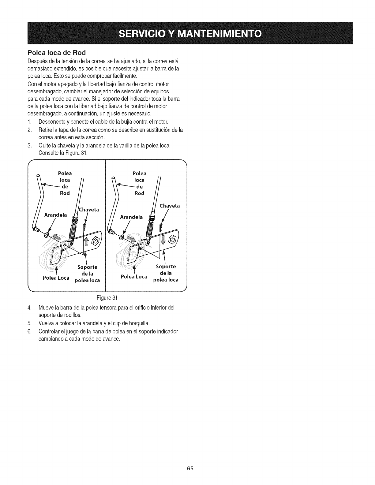
Polea Ioca de Rod
Despu_sdela tensi6nde lacorrease haajustado,si la correaestA
demasiadoextendido,es posiNe que necesiteajustarla barrade la
poleaIoca. Estose puedecomprobarf_.cilmente.
Conel motorapagadoy la libertadbajofianzadecontrolmotor
desembragado,cambiarel manejadorde selecci6ndeequipos
paracadamododeavance.Si el soportedelindicadortocala barra
dela poleaIocacon la libertadbajo fianzade controlde motor
desembragado,a continuaci6n,un ajustees necesario.
1. Desconectey conecteelcablede la bujfacontra el motor.
2. Retirela tapade lacorreacomo sedescribeen sustituci6nde la
correaantesen esta secci6n.
3. Quitela chavetay la arandelade la varillade lapoleaIoca.
Consultela Figura31.
f
Polea
Iota
Soporte
de la
Polea Loca polea Iota
Chaveta
/
Polea Loca
Soporte
dela
polea Iota
Figure31
4. Muevela barra de la poleatensorapara el orifido inferiordel
soportede rodillos.
5. Vuelvaa colocarla arandelay el clip de horquilla.
6. Controlareljuegode la barrade poleaenel soporteindicador
cambiandoa cadamodode avance.
65
Nuncaalrnacenela cultivadoraconcombustibleenel tanqueenun
espaciocerradoo en _.reaspocoventiladasdondelos gasesdel
combustiblepuedanNegara una Narnaexpuesta,unachispao un
pilotocornoel que tienenalgunoshornos,calentadoresde agua,
secadoresde ropao algQnartefactoa gas.
Nuncadejeel motorsin vigilanciarnientrasest,.en funcionarniento.
PREPARACI6N DEL MOTOR
Paraalrnacenarrnotoresentre 30y 90dfases necesariotratarlos
con un estabiNzadorde gasolinay paraalrnacenarlosdurantern_.s
de 90dfasse debe drenarel combustiblepara evitardeteriorosy la
forrnaci6ndedep6sitosde gornaen el sisternade combustibleo en
piezasfundarnentalesdelcarburador.Sila gasolinaen su motorse
deterioraduranteel alrnacenarniento,es posiblequedebareparar
o reernplazarel carburadory otros cornponentesdel sisternade
combustible.
1. Extraigatodo el combustibledeldep6sitohaciendofuncionarel
motorhastaquese detengapor falta de combustible.
2. Carnbieel aceite.Consulteel Carnbiode aceiteen la secci6n
SERVlCIOY MANTENIMIENTO.
3. Retirelabujfay viertacerca de 1/2onzade aceiteparamotor
en elciNndro.Vuelvaa colocarla bujfay d_ rnarchaalmotor
lentarnentepara distribuirelaceite.
4. Lirnpiela suciedadde las _.reasdel motory del silenciador.
RetoquelapinturadaSada,y revistaotras_.reasque puedan
oxidarsecon una pelfculadelgadadeaceite.
5. Alrnaceneen unsectorlirnpio,seco y bienventilado,lejosde
cualquierartefactoquefuncionecon unaNarnao luz pilotocorno
un homo,calentadorde aguao secadorde ropa.Tarnbi_nevite
cualquiersectorcon unachispaproduciendomotorel_ctricoo
dondese utilizanherrarnientasel_ctricas.
6. Deser posible,tarnbi_nevita_.reasde alrnacenarnientocon
rnuchahurnedadpara evitaroxidaci6ny corrosi6n.
7. Mantengael motorniveladocuandoIoalrnacene.Lainclinaci6n
del motorpuederesultarenfugas de combustibleo aceite.
PREPARACI6N DE LA CULTIVADORA
Si la cultivadorano se va a usarduranteun perfodoprolongado,
prep_.relaparael alrnacenarnientodela siguienteforrna:
1. Lirnpiela cultivadoray el motor.
2. Siga las recornendacionessobrelubricaci6ny verifiquesi hay
parteso piezassueltas.
3. Alrnacenela cultivadoraen un_.realirnpiay seca.
4. Nuncaalrnacenelacultivadoraconcombustibleenel tanqueen
un _.reacerradadondelas ernanacionesde la gasoNnapueden
alcanzarunaNarnaexpuestaochispas,o dondehubierefuentes
de encendido(calefactores,calentadoresde agua,hornos,etc.).
66
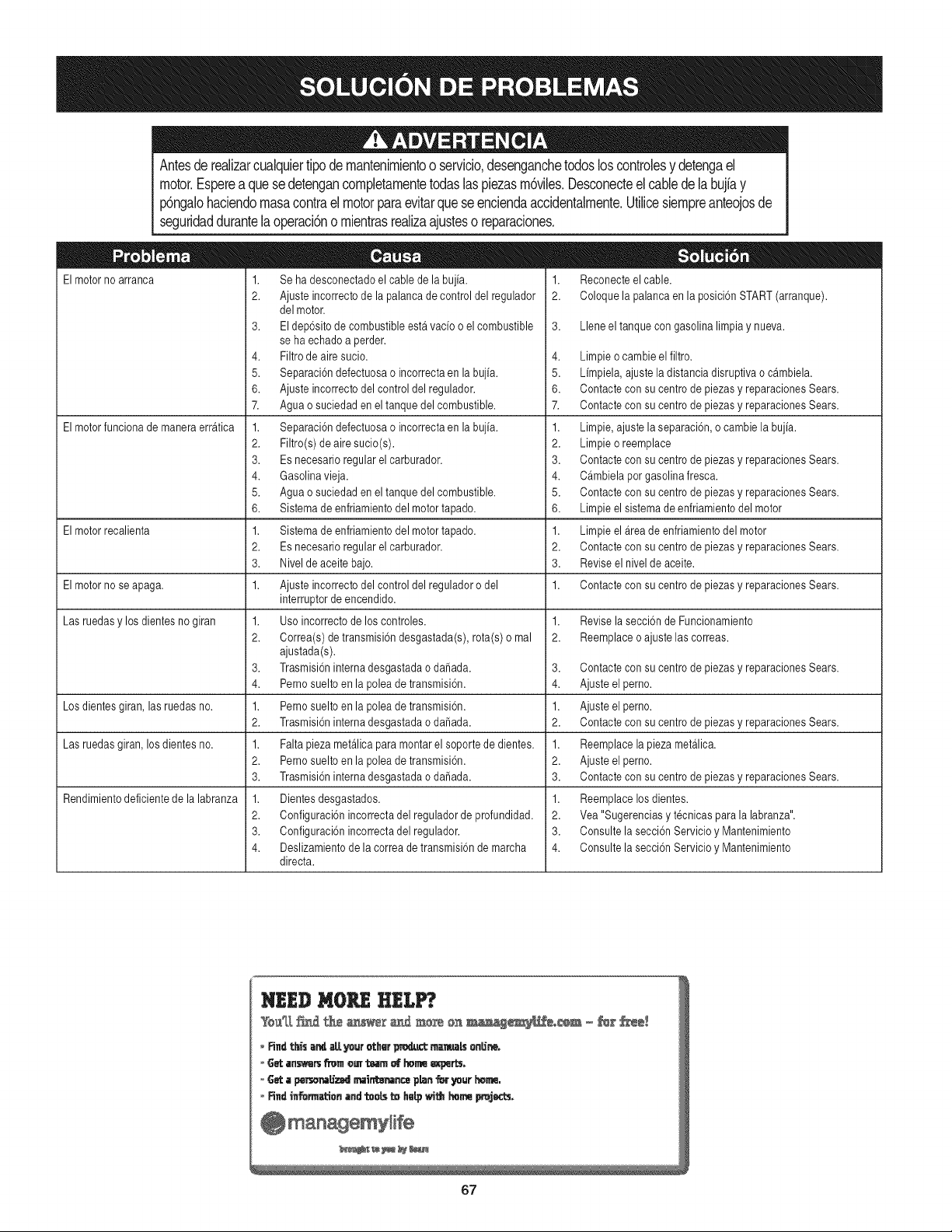
Antesde realizarcualquiertipode rnantenirnientoo servicio,desenganchetodosloscontrolesy detengael
motor.Espereaquesedetengancornpletarnentetodaslaspiezasrn6viles.Desconecteel cabledelabujfay
p6ngalohaciendornasacontraelmotorparaevitarqueseenciendaaccidentalrnente.Utilicesiernpreanteojosde
seguridaddurantelaoperaci6no rnientrasrealizaajusteso reparaciones.
El motor no arranca
El motorfunciona de manera erratica
1. Reconecteel cable.
2. Coloque la palancaen la posici6nSTART(arranque).
3. Llene el tanquecon gasolina limpiay nueva.
1. Se ha desconectadoel cable de la bujfa.
2. Ajusteincorrecto de la palancade control del regulador
delmotor.
3. Eldep6sito de combustibleestavacfo o elcombustible
seha echado a perder.
4. Filtrode aire sucio.
5. Separaci6ndefectuosao incorrectaen la bujia.
6. Ajusteincorrecto delcontrol del regulador.
7. Aguao suciedaden el tanque del combustible.
1. Separaci6ndefectuosao incorrectaen la bujia.
2. Filtro(s) de aire sucio(s).
3. Es necesario regularel carburador.
4. Gasolinavieja.
5. Aguao suciedaden el tanque del combustible.
6. Sistemade enfriamientodelmotor tapado.
1. Sistemade enfriamientodelmotor tapado.
2. Es necesario regularel carburador.
3. Nivelde aceite bajo.
1. Ajusteincorrecto delcontrol del reguladoro del
interruptorde encendido.
1. Usoincorrecto de los controles.
2. Correa(s)de transmisi6ndesgastada(s), rota(s) o mal
ajustada(s).
3. Trasmisi6ninternadesgastada o dafiada.
4. Pernosuelto en la polea de transmisi6n.
1. Pernosuelto en la polea de transmisi6n.
2. Trasmisi6ninternadesgastada o dafiada.
1. Falta piezametalica para montarel soporte de dientes.
2. Pernosuelto en la polea de transmisi6n.
3. Trasmisi6ninternadesgastada o dafiada.
1. Dientesdesgastados.
2. Configuraci6nincorrecta del reguladorde profundidad.
3. Configuraci6nincorrecta del regulador.
4. Deslizamientode la correa de transmisi6nde marcha
directa.
El motor recalienta
El motor no seapaga. Contacte con su centrode piezas y reparacionesSears.
Las ruedasy los dientesno giran
Los dientesgiran, las ruedas no.
Las ruedasgiran, los dientes no.
Rendimientodeficiente de la labranza
4. Limpieo cambieel filtro.
5. Limpiela, ajuste ladistancia disruptiva o cambiela.
6. Contacte con su centrode piezas y reparacionesSears.
7. Contacte con su centrode piezas y reparacionesSears.
1. Limpie,ajuste la separaci6n,o cambie la bujia.
2. Limpieo reemplace
3. Contacte con su centrode piezas y reparacionesSears.
4. Cambiela por gasolina fresca.
5. Contacte con su centrode piezas y reparacionesSears.
6. Limpieel sistemade enfriamientodel motor
1. Limpieel Areade enfriamientodel motor
2. Contacte con su centrode piezas y reparacionesSears.
3. Reviseel nivelde aceite.
1.
1. Revisela secci6n de Funcionamiento
2. Reemplaceo ajuste las correas.
3. Contacte con su centrode piezas y reparacionesSears.
4. Ajuste el perno.
1. Ajuste el perno.
2. Contacte con su centrode piezas y reparacionesSears.
1. Reemplacela piezametalica.
2. Ajuste el perno.
3. Contacte con su centrode piezas y reparacionesSears.
1. Reemplacelos dientes.
2. Yea "Sugerenciasy t_cnicas para la labranza".
3. Consulte la secci6n Servicio y Mantenimiento
4. Consulte la secci6n Servicio y Mantenimiento
67

68
(Esta p_.ginase aplica s61oen EE.UU. y Canada.).
Sears Brands Management Corporation, el Consejo de Recursos Ambientales de California (CARB)
y la Agencia de Protecci6n Ambiental de los Estados Unidos (EPA)
Declaraci6n de garantia del sistema de control de emisiones (derechos y obligaciones de la garanfia de defectos del propi=
etario)
LA COBERTURADE LA GARANTJADE CONTROLDEEMISIONESES Y PARALOSMODELOSCERTIFICADOSDELANO 1997YPOSTERIORES,
APLIOABLEA LOS MOTORESCERTIFICADOSCOMPRADOSENCALIFOR- QUESE COMPRENY UTILICENEN CUALQUIERPARTEDE LOSESTADOS
NIA EN1995Y POSTERIORMENTE,QUESE UTILIZANENCALIFORNIA, UNIDOS(Y A PARTIRDEL 1 DE ENERODE 2001 ENCANADA).
Declaraci6n de garanfia sobre defectos en el control de emisiones para California y los Estados Unidos
ElConsejode RecursosAmbientalesde California(CARB),la EPA(Agencia
de Protecci6nAmbientalde los EE.UU.)y Searstienenel gusto de explicarla
garantiadel sistemade control de emisionesparamotoresdela_o 2000y para
elfuturo con relaci6na motorespeque_ostodo terreno(SORE).En California,
los nuevosmotorespeque_ostodo terrenodebenestar dise_ados,construidos
y equipadosparacumplircon las rigurosasnormasanti-smogdelestado.En
el restode los EstadosUnidos,losmotoresnuevostodoterrenode encendido
porchispacertificadosparael a_o 1997debencumplirest_ndaressimilares
establecidospot la EPA.Sears debegarantizarel sistemade control de emis-
ionesde su motorpara losperiodosde tiempoenumeradosa continuaci6n,
siemprequeno hayaabuso,negligenciao mantenimientoindebidode su
motortodoterrenopeque_o.Su sistemade controlde emisionespuedeincluir
piezastalescomoel carburador,el filtro de aire, el sistemade encendido,el
silenciadoryel conversorcatalitico.Tambienpuedeincluirconectoresyotras
unidadesrelacionadascon las emisiones.Dondeexistaunacondici6ncubierta
por la garantia,Searsreparar_su peque6omotortodo terrenosin costoalguno
incluyendodiagn6stico,piezasy manode obra
Cobertura de la garantJa Sears para defectos en el control de emJsiones
Los motorestodo terrenopeque6osest_ngarantizadosen Io relativoalcontrol alas disposicionesque se indiquena continuaci6n.Si una parte de su motor
de emisionesparadefectosenpiezasduranteun periodode dos a_os,sujeto cubiertapot lagaranfiaes defectuosa,Sears reparar_o sustituir_dichaparte.
Responsabilidades del propietario en relacibn con la garantia
Comopropietariodel motortodo terrenopeque_o,Ud.es responsablede la
realizaci6ndel mantenimientorequeridoquese incluyeen las instrucciones
de operaci6ny mantenimiento.Searsrecomiendaquese conserventodoslos
recibosrelativosal mantenimientode su motortodoterrenopeque_o,pero
no pude denegarla garantiasimplementepor la faltade los mismos,o por su
incumplimientodel mantenimientoprogramatic.Comopropietariodel motor
peque_otodoterrenodebe saberque, sinembargo,Sears lepuedenegar
lacoberturade lagarantiasi su motortodoterrenopeque6oouna piezadel
mismohanfalladodebido a abuso,negligencia,mantenimientoindebidoo
a modificacionesno aprobadas.Ud.es responsablede presentarsu motor
todoterrenopeque6oa un distribuidorde serviciosSearsautorizadotan pronto
comoaparezcaun problema.Las reparacionesdela garantiasinconfiicto
debencompletarseen un plazode tiempo razonable,no superiora 30 dias.Si
tienealgunapreguntarespectoa sus derechosy responsabilidadesreferen-
tes a la garantia,debe contactarcon un representantede serviciosSearsal
1--800--469--4663.La garantiade emisioneses unagarantiapor defectos.Los
defectosse juzgande acuerdocon elfuncionamientonormalde un motor.La
garantiano est_relacionadacon unapruebade emisionesenuso.
Disposiciones de la garantJa Sears para defectos en el control de emJsiones
Las siguientesson disposicionesespecificasrelacionadascon la coberturade lagarantia paradefectosen el controlde emisiones.Esun a_adidoa lagarantiade
motorSearsparamotoresno reguladosque seencuentraen lasinstruccionesde funcionamientoy mantenimiento.
1. Piezascon garantia
La coberturade esta garantiase extiendeL]nicamentealas piezas
queaparecena continuaci6n(las partesde lossistemasde control de
emisiones),siempreque dichas piezasestuvieranya en el motoren el
momentode su compra.
a. Sistemade medici6n de combustible
• Sistema de enriquecimientopara arranqueen frio
• Carburadory partesinternas
• Bombade combustible
b. Sistemade inducci6nde aire
• Filtrode aire
• Colector de admisi6n
c. Sistemadeencendido
• Bujia(s)de encendido
• Sistema de encendidomagneto
d. Sistemadelcatalizador
• Convertidorcatalitico
• Colector de escape
• Sistema de inyecci6nde aireo v_lvulade impulsos
e. Elementosvariadosusadosen lossistemasanteriores
• Wlvulas devacio,sensiblesa temperatura,posici6ny tiempo
e interruptores
• Conectoresy montajes
2. AIcancede la cobertura
Searsgarantizaal poseedorinicialy a loscompradoressubsiguientes
quelas piezas con garantiano tendr_ndefectosen materialesni mano
de obra que provoquenla falla de las mismasduranteun periodode
dos aSosa partir de la fechaen queel motorse entregaa un comprador
particular.
3. Sin cargo
La reparaci6no reemplazodecualquierpartecon garantia se realizar_
sin cargo alguno parael poseedor,incluyendotareas de diagn6sticoque
permitandeterminarsi una partecon garantiaes defectuosa,siempreque
dichodiagn6sticose realiceen un distribuidorde serviciosSearsautoriza-
do. Parael servicio de lagarantia de emisiones,contacteal distribuidorde
serviciosSearsautorizadom_scercanoincluidoen las"P_ginasamarillas"
en lascategorias"Motores,gasolina","Motoresde gasolina","Podadoras
de cesped",o similares.
4. Reclamacionesyexclusionesa la cobertura
Las reclamacionesde lagarantia debenenviarsede acuerdocon las
disposicionesde la politica de garantia para motoresSears.La cobertura
de lagarantia excluir_defectosen piezascon garantia queno scan partes
originalesSears,o abuso,negligenciao mantenimientoincorrecto,tal y
como se estableceen la politica de garantia para motoresSears.Sears no
es responsablede lasfallas en piezascon garantia provocadaspor el uso
de partesa6adidas,que no scan originaleso quese hayan modificado.
5. Mantenimiento
Cualquierpartecon garantiaque no este programadaparaserreem-
plazadacomomantenimientorequerido,o que s61odebainspeccionarse
regularmentealefecto de "inspeccioneo reemplacesegL]nsea necesario",
estar_garantizadacontradefectosduranteel periodode la garantia.Todas
las piezasgarantizadasqueesten programadaspara su reemplazopara
cumplir con los requisitosde mantenimientoestar_ngarantizadass61o
por el periodoanterior al primerreemplazoprogramaticparadicha pieza.
Cualquierpiezade recambioquesea equivalenteen funcionamientoy
durabilidadpuedeusarsepararealizarmantenimientoo reparaciones.El
propietarioes responsablede realizartodoel mantenimientorequerido,tal
y comose define en las instruccionesde funcionamientoy mantenimiento
Sears
6. Coberturaindirecta
Porla presente,la coberturase extiendea la falla de cualquiercomponente
de motorprovocadapot lafalla de unapieza con garantiaque estetodavia
en periodode garantia.
En los EstadosUnidosy Canad_hayunalinea de atenci6nde24 horas,1-800-469--4GG3,quecuentacon un menL]con mensajespre-grabadosque contienen
informaci6npara el mantenimientode motores.
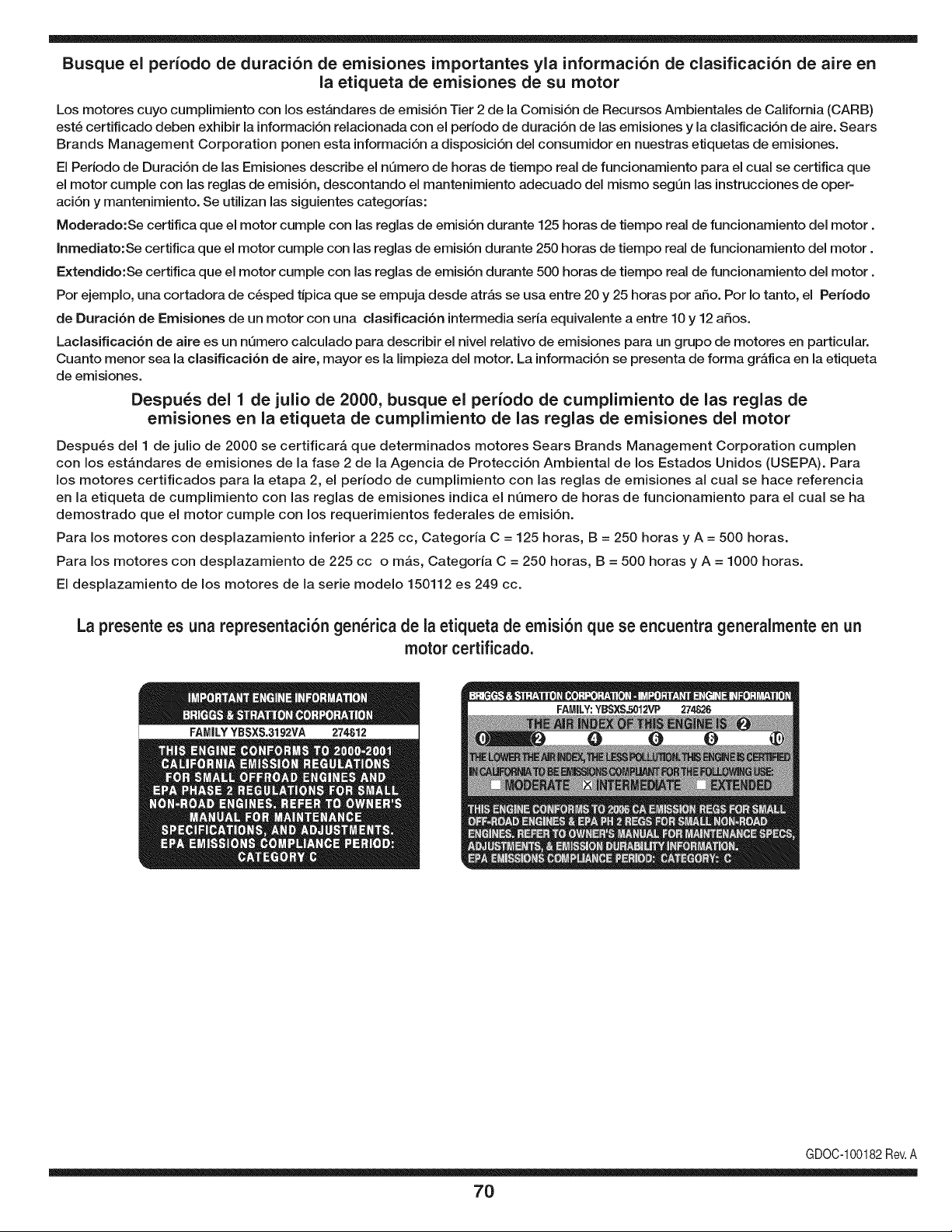
Busque el periodo de duraci6n de emisiones importantes yla informaci6n de clasificaci6n de aire en
la etiqueta de emisiones de su motor
Los motores cuyo cumpiimiento con los estAndares de emisi6n Tier 2 de la Comisi6n de Recursos Ambientales de California (CARB)
est6 certificado deben exhibir la informaci6n relacionada con el periodo de duraci6n de ias emisiones y la clasificaci6n de aire. Sears
Brands Management Corporation ponen esta informaci6n a disposici6n del consumidor en nuestras etiquetas de emisiones.
Ei Periodo de Duraci6n de las Emisiones describe el nQmero de horas de tiempo real de funcionamiento para el cuai se certifica que
el motor cumpie con ias reglas de emisi6n, descontando el mantenimiento adecuado del mismo segQn las instrucciones de oper-
aci6n y mantenimiento. Se utilizan las siguientes categonas:
Moderado:Se certifica que el motor cumpie con las reglas de emisi6n durante 125 horas de tiempo real de funcionamiento del motor.
Inmediato:Se certifica que el motor cumpie con las reglas de emisi6n durante 250 horas de tiempo real de funcionamiento del motor.
Extendido:Se certifica que el motor cumpie con las reglas de emisi6n durante 500 horas de tiempo real de funcionamiento del motor.
Por ejemplo, una cortadora de c6sped tJpica que se empuja desde arras se usa entre 20 y 25 horas por aSo. Por Io tanto, el Periodo
de Duraci6n de Emisiones de un motor con una clasificaci6n intermedia sena equivaiente a entre 10 y 12 aSos.
Laciasificaci6n de aire es un nQmero calculado para describir el nivel relativo de emisiones para un grupo de motores en particular.
Cuanto menor sea la clasificaci6n de aire, mayor es la limpieza del motor. La informaci6n se presenta de forma grAfica en la etiqueta
de emisiones.
Despu_s del 1 de julio de 2000, busque el periodo de cumplimiento de las reglas de
emisiones en la etiqueta de cumplimiento de las reglas de emisiones del motor
Despu6s del 1 de julio de 2000 se certificarA que determinados motores Sears Brands Management Corporation cumplen
con los estAndares de emisiones de la fase 2 de la Agencia de Protecci6n Ambientai de los Estados Unidos (USEPA). Para
los motores certificados para la etapa 2, el periodo de cumplimiento con ias reglas de emisiones al cual se hace referencia
en la etiqueta de cumplimiento con las reglas de emisiones indica el nQmero de horas de funcionamiento para el cual se ha
demostrado que el motor cumple con los requerimientos federales de emisi6n.
Para los motores con desplazamiento inferior a 225 cc, Categoria C = 125 horas, B = 250 horas y A = 500 horas.
Para los motores con desplazamiento de 225 cc o mAs, Categoria C = 250 horas, B = 500 horas y A = 1000 horas.
El desplazamiento de los motores de la serie modelo 150112 es 249 cc.
La presente es una representaci6n gen_rica de la etiqueta de emisi6n que se encuentra generaimente en un
motor certificado.
FAMILYYBSXS.3192VA 274812
GDOC-100182Rev.A
70
Felicitaciones por haber realizado una adquisici6n inteligente. El producto Craftsman® que ha
adquirido esta diseSado y fabricado para brindar muchos aSos de funcionamiento confiable. Pero
como todos los productos a veces puede requerir de reparaciones. Es en ese momento cuando el
disponer de un Acuerdo de protecci6n para reparaciones le puede ahorrar dinero y problemas.
A continuaci6n se detallan los puntos incluidos en el Acuerdo:
[] Servicio experto prestadopor nuestros 10,000 especialistas en reparaciones profesionales
[] Servicio ilirnitado sin cargo para las piezasy la mano de obra en todas las reparacionescubiertas
[] Reernplazo del producto hasta 1500 d61aressi no es posible reparar el producto cubierto
[] Descuento de 25% del precio normal del servicio y de las piezas relacionadas con el mismo que no esten cubiertas
por el acuerdo; ademas, 25% del precio normal de laverificaci6n de mantenimientopreventivo
[] Ayuda r_pida pot tel_fono - Io IlamamosResoluci6n RApida- el apoyo telef6nico de un Chamusca al representante.
Piense en nosotros como el manual "de un dueSo hablador."
Una vez adquirido el Acuerdo, puede programar el servicio con tan s61orealizar una Ilamadatelef6nica. Puede Ilamaren
cualquier momento del dia o de la noche o programar un servicio en linea.
ElAcuerdo de Protecci6nde Reparaci6nes una compra sin riesgo. Si usted anula por alguna raz6n duranteel periodo de
garantia de producto, proporcionaremos un reembolso Ileno.O, un reembolso prorrateado en cualquier momentodespues
del periodo de garantia de producto expira, iAdquiera hoy su acuerdode protecci6n para reparaciones!
Se aplican determinadas limitaciones y exclusiones. Para obtener informaciTn adicional y precios en los Estados
Unidos Ilame al 1-800-827-6655.
El *Coverage en Canad_ivaria en algunos articulos. Para detalles Ilenos la Ilamada Chamusca Canad_ien 1-800-
361-8885.
Servicio de instalaci6nde Sears
Si desea solicitar la instalaci6n profesionalde Sears de aparatosdomesticos, dispositivos paraabrir portones, calentado-
res de agua y otros articulos domesticos importantes, en los Estados Unidos o Canada flame al 1-800-4-MY-HOME®.
71

Your Home
For troubleshooting, product manuals and expert advice:
managernylife
www.managemylife.com
For repair - in your home - of all major brand appliances,
lawn and garden equipment, or heating and cooling systems,
no matter who made it, no matter who sold it!
For the replacement parts, accessories and
owner's manuals that you need to do-it-yourself.
For Sears professional installation of home appliances
and items like garage door openers and water heaters.
1-800-4-MY-HOME ® (1-800-469-4663)
Call anytime, day or night (U.S.A. and Canada)
www.sears.com www.sears.ca
Our Home
For repair of carry-in items like vacuums, lawn equipment,
and electronics, call anytime for the location of your nearest
Sears Parts & Repair Service Center
1-800-488-1222 (U.S.A.) 1-800-469-4663 (Canada)
www.sears.com www.sears.ca
To purchase a protection agreement on a product serviced by Sears:
1-800-827-6655 (U.S.A.) 1-800-361-6665 (Canada)
Para pedir servicio de reparaci6n
a domicilio, y para ordenar piezas:
1-888-SU-HOGAR ®
(1-888-784-6427)
www.sears.com
Au Canada pour service en frangais:
1-800-LE-FOYER Mc
(1-800-533-6937)
www.sears.ca
® Registered Trademark / TMTrademark of KCD IP, LLC in the United States, or Sears Brands, LLC in other countries
® Marca Registrada ! TMMarca de Fabrica de KCD IP, LLC en Estados Unidos, o Sears Brands, LLC in otros paises
MCMarque de commerce ! MDMarque deposee de Sears Brands, LLC