Owner's Manuam
I(:RRFTSMnN°I
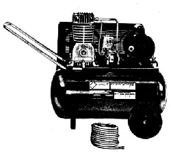
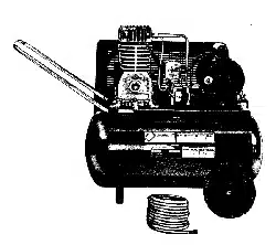
PermanentJy Lubricated
Tank Mounted
AIR COMPRESSOR
ModeJ No.
o
o
o
o
o
o
o
Safety Guidelines
Assembly
Operation
Maintenance
Service and Adjustments
Repair Parts
CAUT|ON: Read the Safety Guidelines
and All instructions CarefulIy Before
Operating.
Sears, Roebuck and Co., Hoffman Estates, IL (}0179 U.S.A.
Visit our Oraftsman website: www, sears,com/craftsman
A13640 R_v.0 11/16/0s
WARRANTY ................................................ 2
SPECiFiCATiON CHART ..................................... 3
SAFETY GUiDELiNES ...................................... 3-8
GLOSSARY ................................................ 9
ACCESSORIES ............................................. 9
DUTY CYCLE .............................................. 9
ASSEMBLY ............................................... 10
iNSTALLATiON ......................................... 10-11
OPERATION ........................................... 12-14
MAINTENANCE ............................................ 15
SERVICE AND ADJUSTMENTS ............................ 16-17
STORAGE ................................................ 18
TROUBLESHOOTING GUIDE ............................. 19-21
REPAIR PARTS ......................................... 22-25
ESPAt_OL .............................................. 26-47
NOTES/NOTAS ............................................ 46
REPAIR PROTECTION AGREEMENTS ......................... 47
HOW TO ORDER REPAIR PARTS ...................... back cover
FULL ONE YEAR WARRANTY AIR COMPRESSOR
If this CRAFTSMAN Air Compressor fails due to a defect in material or
workmanship within one year from the date of purchase, Sears will at
its option repair or replace it free of charge. Contact your nearest Sears
Service Center (1-800-4-MY-HOME <e)to arrange for repair, or return the Air
Compressor to the place of purchase for replacement.
If this Air Compressor is used for commercial or rental purposes, this warranty
applies for only ninety days from the date of purchase.
This warranty gives you specific legal rights and you may have other rights
which vary from state to state.
Sears, Roebuck and Co., Dept. 817WA, Hoffman Estates, IL 60179
A13640 2= ENG
' " _ O m ± ( )(h,
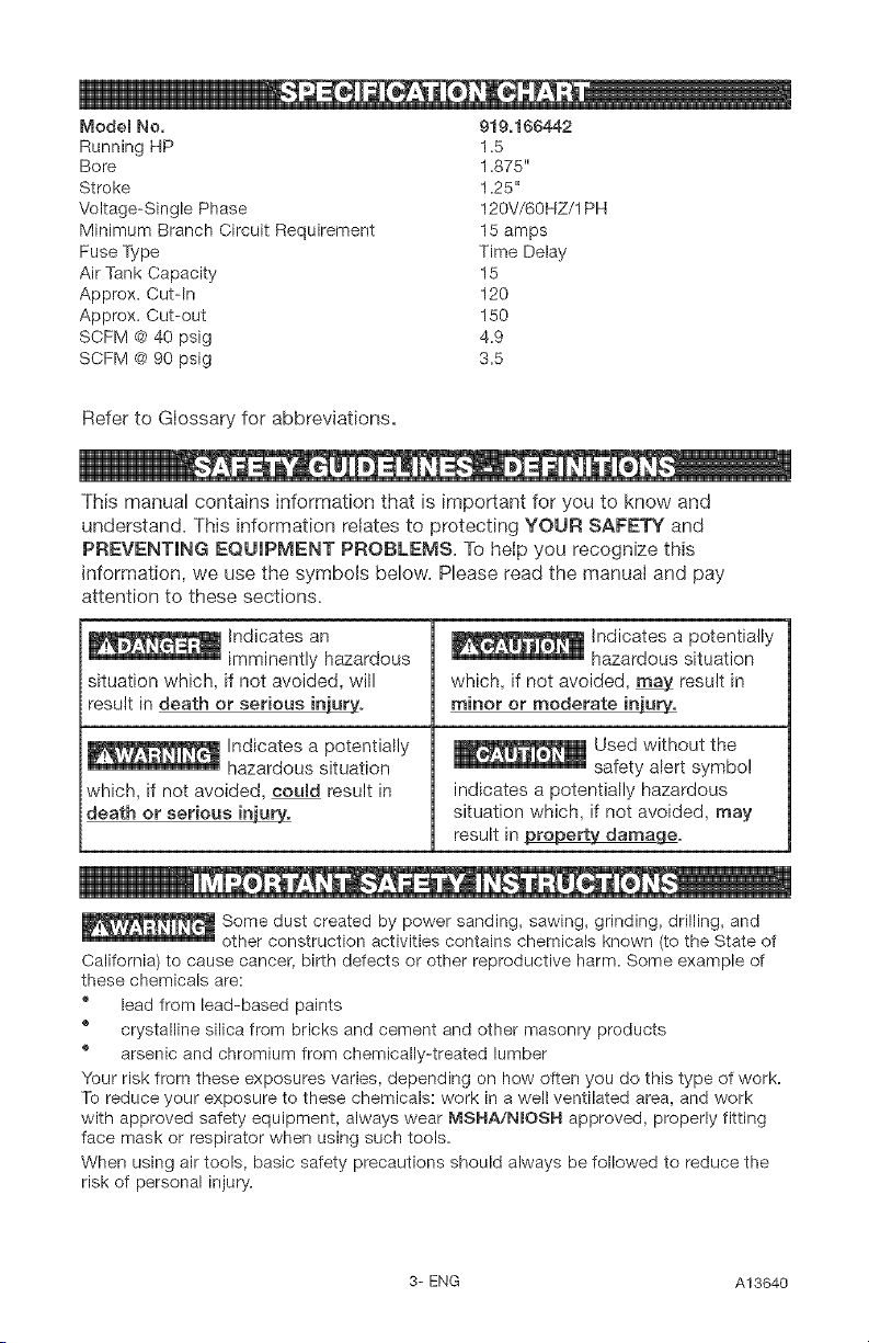
Model No. 919,166442
Running HP 1.5
Sore 1.875"
Stroke 1.25"
Voltage-Single Phase 120V/60HZ/1 PH
Minimum Branch Circuit Requirement 15 amps
Fuse Type Time Delay
Air Tank Capacity 15
Approx. Cut-In 120
Approx. Cut-out 150
SCFM @ 40 psig 4.9
SCFM @ 90 psig 3.5
Refer to Giossary for abbreviations.
)))(,
This manual contains information that ls important for you to know and
understand. This information relates to protecting YOUR SAFETY and
PREVENTING EQUIPMENT PROBLEMS. To help you recognize this
information, we use the symbols below. Please read the manual and pay
attention to these sections.
Indicates an
imminently hazardous
situation which, if not avoided, will
result in death or serious injur_o
Indicates a potentially
hazardous situation
which, if not avoided, ooumd result in
death or serious ini_
Indicates a potentially
hazardous situation
which, if not avoided, may result in
minor or moderate inu_.
Used without the
safety alert symbol
indicates a potentiaUy hazardous
situatioe which, if not avoided, may
result in _ge=
Some dust created by power sanding, sawing, grinding, drilling, and
other construction activities contains chemicals known (to the State of
California) to cause cancer, birth defects or other reproductive harm. Some example of
these chemicals are:
" lead from lead-based paints
® crystalline silica from bricks and cement and other masonry products
" arsenic and chromium from chemically-treated lumber
Your risk from these exposures varies, depending on how often you do this type of work.
To reduce your exposure to these chemicals: work in a well ventilated area, and work
with approved safety equipment, always wear MSHA/NIOSH approved, properly fitting
face mask or respirator when using such tools.
When using air tools, basic safety precautions should always be followed to reduce the
risk of personal injury.
3= ENG A13640
iiii_,....
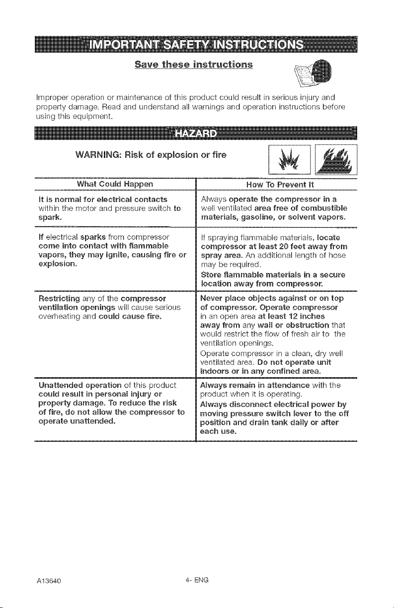
Save these instructions
Improper operation or maintenance of this product could result in serious injury and
property damage. Read and understand all warnings and operation instructions before
using this equipment.
iiiiii_, b
WARNING: Risk of explosion or fire ,._._
What Could Happen
It is normal for electricaR contacts
within the motor and pressure switch to
spark.
If electrical sparks from compressor
come into contact with flammable
vapors, they may ignite, causing fire or
explosion.
Restricting any of the compressor
ventilation openings will cause serious
overheating and could cause fire.
Unattended operation of this product
could result in personal injury or
property damage. To reduce the risk
of fire, do not allow the compressor to
operate unattended.
How To Prevent it
Always operate the compressor in a
well ventilated area free of combustible
materiams, gasoline, or somvent vapors.
if spraying flammable materials, locate
compressor at least 20 feet away from
spray area. An additional length of hose
may be required.
Store flammable materials in a secure
location away from compressor.
Never place objects against or on top
of compressor. Operate compressor
in an open area at least 12 inches
away from any wan or obstruction that
would restrict the flow of fresh air to the
ventilation openings=
Operate compressor in a clean, dry well
ventilated area= Do not operate unit
indoors or in any confined area.
Amways remain in attendance with the
3roduct when it is operating.
Always disconnect eBectrical power by
moving pressure switch lever to the off
;osition and drain tank daily or after
each use.
A13640 4= ENG
111¸¸ D 11!1
iiiiiiiii_, III!
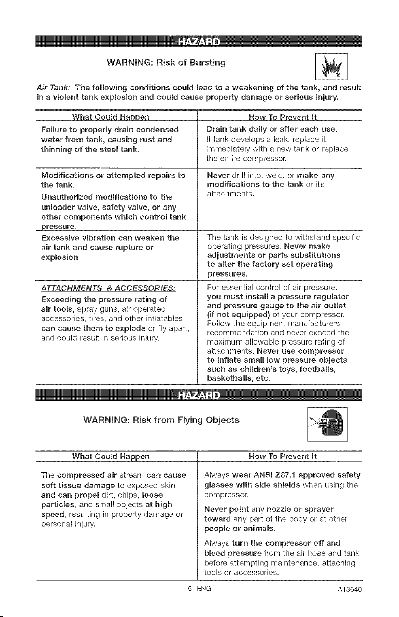
WARNING: Risk of Bursting
Air Tank: The following conditions could lead to a weakening of the tank, and result
in a violent tank explosion and could cause property damage or serious injury.
What Coumd Hal2pen
Failure to properly drain condensed
water from tank, causing rust and
thinning of the steer tank.
Modifications or attempted repairs to
the tank.
Unauthorized modifications to the
unRoader valve, safety valve, or any
other components which controm tank
. pressure.
Excessive vibration can weaken the
air tank and cause rupture or
expBosion
ATTACHMENTS & ACCESSORIESr
Exceeding the pressure rating of
air tooms, spray guns, air operated
accessories, tires, and other inflatables
can cause them to expmode or fly apart,
and could result in serious injury.
Now "re Prevent It
Drain tank daily or after each use.
If tank develops a leak, replace it
immediately with a new tank or replace
the entire compressor.
Never drill into, weld, or make any
modifications to the tank or its
attachments.
The tank is designed to withstand specific
operating pressures. Never make
adjustments or parts substitutions
to aBter the factory set operating
pressures.
For essential control of air pressure,
you must install a pressure regulator
and pressure gauge to the air outmet
{if not equipped) of your compressor.
Follow the equipment manufacturers
recommendation and never exceed the
maximum allowable pressure rating of
attachments. Never use compressor
to inflate small low pressure objects
such as children's toys, footballs,
basketbaHs, etc.
WARNING: R{sk from Fly{rig Objects
What Coumd Happen How To Prevent It
The compressed air stream can cause
soft tissue damage to exposed skin
and can propel dirt, chips, Boose
particBes, and small objects at high
speed, resulting in property damage or
personal injury.
Always wear ANSi Z87.1 approved safety
glasses with side shieMs when using the
compressor
Never point any nozzle or sprayer
toward any part of the body or at other
people or animals.
Always turn the compressor off and
bleed pressure from the air hose and tank
before attempting maintenance, attaching
tools or accessories.
5- ENG A13640
D m
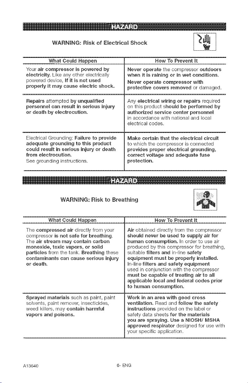
WARNING: Risk of Electrical Shock I _.._ I
What Oeuld Happen
Your air compressor is powered by
eReetricity, Like any other electrically
powered device, If it is not used
properly it may cause electric shock.
Repairs attempted by unqualified
personnel can result in serious injury
or death by electrocution.
Electrical Grounding: Failure to provide
adequate grounding to this product
could result in serious injury or death
from electrocution.
See grounding instructions.
How To Prevent mt
Never operate the compressor outdoors
when it is raining or in wet conditions.
Never operate compressor with
protective covers removed or damaged.
Any emectrical wiring or repairs required
on this product should be performed by
authorized service center personneB
in accordance with national and local
electrical codes.
Make certain that the eBectrical circuit
to which the compressor is connected
provides proper eBectrical grounding,
correct voltage and adequate fuse
protection.
iiiiiiiii_,_
WARNING: R{sk to Breathing
What Could
The compressed air directly from your
compressor is not safe for breathing.
The air stream may contain carbon
monoxide, toxic vapors, or solid
particles from the tank. Breathing these
contaminants can cause serious injury
or death.
Sprayed materials such as paint, paint
solvents, paint remover, insecticides,
weed killers, may contain harmful
vapors and poisons.
Now To Prevent It
Air obtained directly from the compressor
should never be used to supply air for
human consumption. In order to use air
%oduced by this compressor for breathing,
suitable filters and in-line safety
equipment must be property installed.
In-line filters and safety equipment
used in conjunction with the compressor
must be capable of treating air to aH
applicable local and federal codes prior
to human consumption.
Work in an area with good cross
ventilation. Read and follow the safety
instructions provided on the label or
safety data sheets for the materials
you are spraying. Use a NIOSH/MSNA
approved respirator designed for use with
your specific application.
A13640 6- ENG
m k
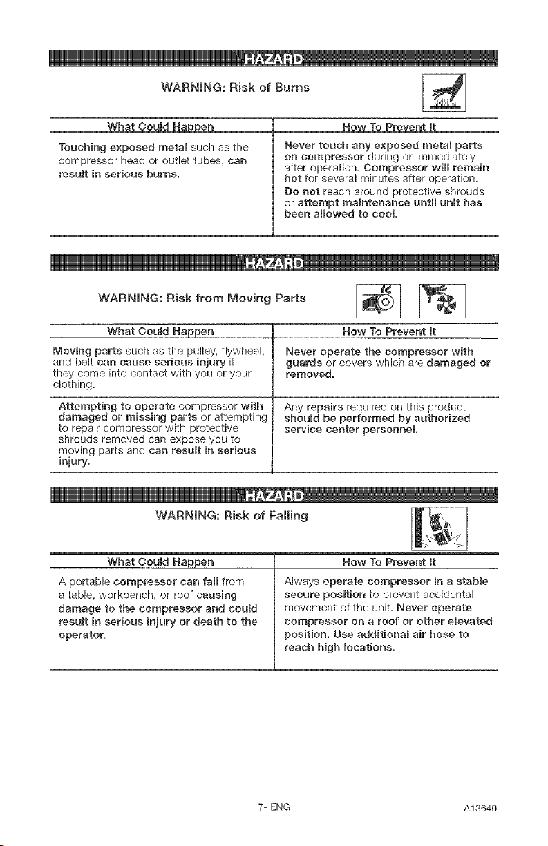
WARNING: Risk of Burns
What Could Ha en
Touching exposed metal such as the
compressor head or outlet tubes, can
result in serious burns.
How To Prevent mt
Never touch any exposed metal parts
on compressor during or immediately
after operation. Compressor will remain
hot for several minutes after operation.
Do not reach around protective shrouds
or attempt maintenance until unit has
been allowed to cool
i11!
WARNING: Risk from Moving Parts
What Could Happen
Moving parts such as the pulley, flywheel,
and belt can cause serious injury if
they come into contact with you or your
clothing.
Attempting to operate compressor with
damaged or missing parts or attempting
to repair compressor with protective
shrouds removed can expose you to
moving parts and can result in serious
injury.
How To Prevent It
Never operate the compressor with
guards or covers which are damaged or
removed.
Any repairs required on this product
should be performed by authorized
service center personnel
iiiiiii_, _ !
WARNING: Risk of Falling
What CouBd Happen
A portable compressor can fall from
a table, workbench, or roof causing
damage to the compressor and eouBd
result in serious injury or death to the
operator.
How To Prevent mt
Always operate compressor in a stable
secure position to prevent accidental
movement of the unit. Never operate
compressor on a roof or other elevated
position. Use additionam air hose to
reach high locations.
7- ENG A13640
WARNING: Risk of Serious Injury or Property Damage When _]
Transporting Compressor
(Fire, Inhalation, Damage to Vehicle Surfaces)
What Could Happen
Oil can leak or spill and could result
in fire or breathing hazard; serious
injury or death can result, oil leaks will
damage carpet, paint or other surfaces
in vehicles or trailers.
How To Prevent it
Always piece COMPRESSOR on a
protective mat when transporting to
protect against damage to vehicle from
leaks. Remove COMPRESSOR from
vehicle immediately upon arrival at your
destination.
_D
WARNING: Risk of Unsafe Operation
What Could Happen ........
Unsafe operation of your air compressor
could lead to serious injury or death to
you or others.
How To Prevent mt
Review and understand all instructions
and warnings in this manual.
Become familiar with the operation and
controls of the air compressor.
Keep operating area dear of all persons,
pets, and obstacles.
Keep children away from the air
compressor at aH times.
Do not operate the product when
fatigued or under the influence of
alcohol or drugs. Stay alert at aH times.
Never defeat the safety features of this
product.
Equip area of operation with a fire
extinguisher.
Do not operate machine with missing,
broken, or unauthorized parts.
SAVE THESE mNSTRUCTmONS
A13640 8- ENG
Become familiar with these terms
before operating the unit.
CFM: Cubic feet per minute.
SCFM: Standard cubic feet per
minute; a unit of measure of air
delivery.
PSlG: Pounds per square inch
gauge; a unit of measure of pressure.
Code Certification: Products that
bear one or more of the following
marks: UL, CUL, ETL, CETL, have
been evaluated by OSHA certified
independent safety Iaboratorles and
meet the applicable Underwriters
Laboratories Standards for Safety.
Cut=in Pressure: While the motor
is off, air tank pressure drops as
you continue to use your accessory.
When the tank pressure drops to a
certain low level the motor will restart
automatically. The low pressure
at which the motor automatically
restarts is called "cut-in" pressure.
Cut-Out Pressure: When an air
compressor ls turned on and begins
to run, air pressure in the air tank
begins to build. It builds to a certain
high pressure before the motor
automatically shuts off, protecting
your air tank from pressure higher
than its capacity. The high pressure
at which the motor shuts off ls called
"cut-out" pressure.
Branch Circuit: C+rcu[t carrying
electricity from electrical panel to
outlet.
This unit is capable of powering the following Accessories. The accessories are
available through the current Power and Hand Tool Catalog or full-line Sears
stores.
Accessories
® In Line Filter
+ Tire Air Chuck
+ Quick Connector Sets (various
sizes)
+ Air Pressure Regulators
® Oil Fog Lubncators
® Air Hose: 1/4", 3/8" or 1/2" LD. in
various lengths
Refer to the selection chart located
on the unit to select the tools this unit
is capable of powering.
This air compressor pump is
capable of running continuously.
However, to prolong the life of your
air compressor, it is recommended
that a 50%-75% average duty
cycle be maintained; that is, the air
compressor pump should not run
more than 30-45 minutes in any given
hour.
9+ ENG A13640
, N
1. Remove unit from carton and
discard a!l packaging.
HOW TO SET UP YOUR
UNiT
Location of the Air Compressor
Locate the air compressor in a
clean, dry and well ventilated area.
The air compressor should be
located at least 12" away from the
wall or other obstructions that will
interfere with the flow of air. The
air compressor pump and shroud
are designed to allow for proper
cooling. The ventilation openings
on the compressor are necessary
to maintain proper operating
temperature. Do not place rags or
other containers on or near these
openings.
iMPORTANT: The outlet being used
must be installed and grounded in
accordance with all local codes and
ordinances.
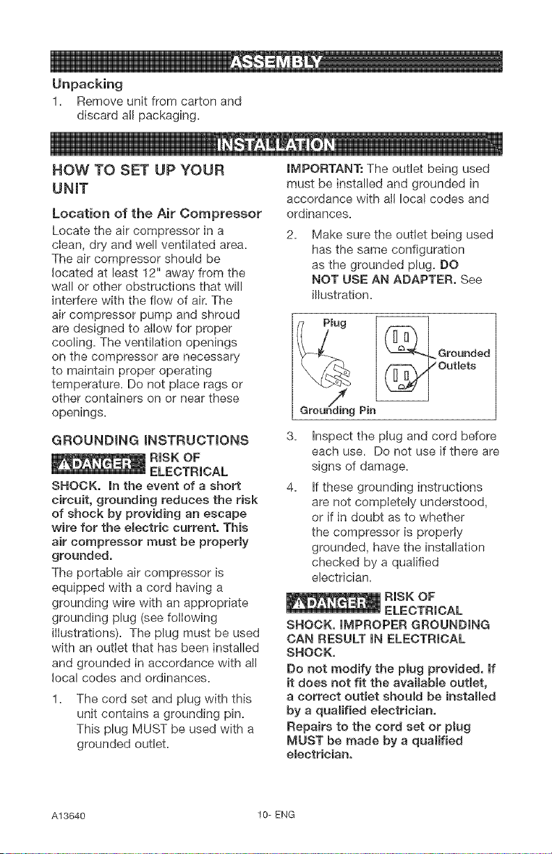
2. Make sure the outlet being used
has the same configuration
as the grounded plug. DO
NOT USE AN ADAPTER, See
illustration.
GROUNDING iNSTRUCTIONS
SHOCK, in the event of a short
circuit, grounding reduces the risk
of shock by providing an escape
wire for the e_ectric current. This
air compressor must be properly
grounded,
The portable air compressor is
equipped with a cord having a
grounding wire with an appropriate
grounding plug (see following
illustrations). The plug must be used
with an outlet that has been installed
and grounded in accordance with all
local codes and ordinances.
1. The cord set and plug with this
unit contains a grounding pin.
This plug MUST be used with a
grounded outleL
3.
4.
Inspect the plug and cord before
each use. Do not use if there are
signs of damage.
If these grounding instructions
are not completely understood,
or if in doubt as to whether
the compressor is properly
grounded, have the installation
checked by a qualified
electrician.
SHOCK, IMPROPER GROUNDING
CAN RESULT IN ELECTRICAL
SHOCK,
Do not modify the plug provided, If
it does not fit the avaimable outlet,
a correct outlet should be installed
by a qualified electrician,
Repairs to the cord set or pJug
MUST be made by a qualified
emectrician,
A13640 10- ENG
Extension Cords
Using extension cords is not
recommended. The use of extension
cords wilI cause voltage to drop
resulting in power loss to the motor
and overheating.
Instead of using an extension cord,
increase the working reach of the
air hose by attaching another length
of hose to its end. Attach additional
lengths of hose as needed.
If an extension cord must be used,
be sure it is:
® a 3-wire extension cord that has
a 3-blade grounding plug, and a
3-slot receptacle that will accept
the plug on the product
® in good condition
® no longer than 50 feet
12 gauge (AWG) or larger. (Wire
size increases as gauge number
decreases. 10 AWG and 8 AWG
may also be used. DO NOT USE
14 OR 16 AWG.)
Voltage and Circuit Protection
Refer to the specification chart for the
voltage and minimum branch circuit
requirements.
air compressors can be operated
on a 15 amp circuit if the following
conditions are met.
1. Voltage supply to circuit must
comply with the National
Electrical Code.
2. Circuit is not used to supply any
other electrica! needs.
3. Extension cords comply with
specifications.
4. Circuit is equipped with a
15 amp circuit breaker or 15
amp time delay fuse. NOTE: If
compressor is connected to a
circuit protected by fuses, use
only time delay fuses. Time delay
fuses should be marked "D" in
Canada and "T" in the US.
If any of the above conditions
cannot be met, or if operation of
the compressor repeatedly causes
interruption of the power, it may be
necessary to operate it from a 20
amp circuit. It is not necessary to
change the cord set.
11-ENG A13640
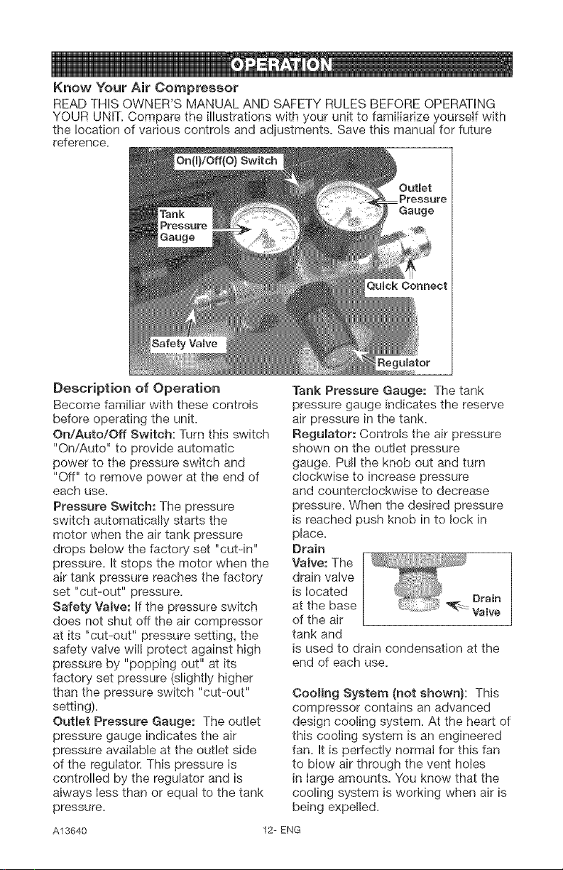
Know Your Air Compressor
READ THiS OWNER'S MANUAL AND SAFETY RULES BEFORE OPERATING
YOUR UNIT. Compare the illustrations with your unit to familiarize yourself with
the !ocation of various controls and adjustments. Save this manual for future
reference.
Description of Operation
Become familiar with these controls
before operating the unit.
On/Auto/Off Switch: Turn this switch
"On/Auto" to provide automatic
power to the pressure switch and
"Off" to remove power at the end of
each use.
Pressure Switch: The pressure
switch automatically starts the
motor when the air tank pressure
drops below the factory set "cut-in"
pressure, it stops the motor when the
air tank pressure reaches the factory
set "cut-out" pressure.
Safety Vamve: if the pressure switch
does not shut off the air compressor
at its "cut-out" pressure setting, the
safety valve wil! protect against high
pressure by "popping out" at its
factory set pressure (slightly higher
than the pressure switch "cut-out"
setting).
Outlet Pressure Gauge: The outlet
pressure gauge indicates the air
pressure avaiIable at the outlet side
of the reguIator. This pressure is
controlled by the regulator and is
always Iess than or equa! to the tank
pressure.
Tank Pressure Gauge: The tank
pressure gauge indicates the reserve
air pressure in the tank.
Regulator: Controls the air pressure
shown on the outlet pressure
gauge. Pull the knob out and turn
cIockwise to increase pressure
and counterclockwise to decrease
pressure. When the desired pressure
is reached push knob in to lock in
place.
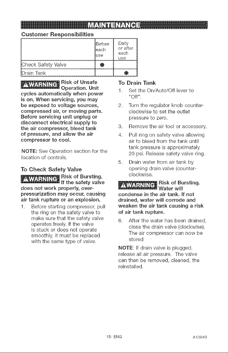
Drain
Valve: The
drain valve
is Iocated
at the base
of the air
tank and
is used to drain condensation at the
end of each use.
Cooling System (not shown): This
compressor contains an advanced
design cooling system. At the heart of
this cooling system is an engineered
fan. it is perfectly norma! for this fan
to blow air through the vent holes
in large amounts. You know that the
cooling system is working when air is
being expelled.
A13640 12-ENG

Air Compressor Pump (not shown):
Compresses air into the air tank.
Working air is not available until the
compressor has raised the air tank
pressure above that required at the
air outlet.
Check Valve:
When the air
compressor is
operating, the
check valve
is "open",
allowing
compressed
air to enter
the air tank.
When the
air compressor reaches "cut-out"
pressure, the check valve "closes",
allowing air pressure to remain inside
the air tank.
How to Use Your Unit
How to Stop:
1. Set the On/Auto/Off lever to
"Off".
Before Starting
Break-in instructions
_Risk of Unsafe
Operation, Serious
damage may result if the following
break-in instructions are not
cmosemyfollowed.
This procedure is required before the
air compressor is put into service and
when the check valve or a complete
compressor pump has been replaced.
1. Make sure the On/Auto/Off lever
is in the "Off" position.
NOTE: If quick connect is installed,
pull coupler back until it clicks to
prevent air from escaping through the
quick connect.
2. Plug the power cord into the
correct branch circuit receptacle.
(Refer to "Voltage and Circuit
Protection" paragraph in the
Installation section of this
manua!.)
3. Open the drain vane fully
(counter-clockwise) to permit
air to escape and prevent air
pressure build up in the air tank
during the break-in period.
4. Move the On/Auto/Off lever
to "On/Auto" position. The
compressor will start.
5. Run the compressor for 15
minutes. Make sure the drain
valve is open and there is
minimal air pressure build-up in
tank.
6. After 15 minutes, close the drain
valve (clockwise). The air receiver
will fill to "cut-out" pressure and
the motor will stop.
The compressor is now ready for use.
Before Each Start-Up:
1. Place On/Auto/Off lever to "Off".
2. Pull regulator knob out, turn
counter-clockwise until it stops.
Push knob in to lock in place.
3. Attach hose and accessories.
NOTE: The hose or accessory
will require a quick connect plug
if the air outlet is equipped with a
quick connect.
pressure causes a hazardous risk of
bursting, Check the manufacturer's
maximum pressure rating for air
tools and accessories, The regulator
outlet pressure must never exceed
the maximum pressure rating,
13-ENG A13640
How to Start:
1. Turn the On/Auto/Off lever
to "On/Auto" and allow tank
pressure to build. Motor will
stop when tank pressure reaches
"cut-out" pressure,
2. Pull the regulator knob out
and turn clockwise to increase
pressure. When the desired
pressure is reached push knob in
to Iock in place. The compressor
is ready for use.
NOTE: Always operate the air
compressor in wetI-ventilated areas
free of gasoline or other combustible
vapors, if the compressor is being
used to operate a sprayer DO NOT
place near the spray area.
A13640 14-ENG
Customer Responsibilities
Before Daily
each or after
each
use
use
_heck Safety Valve
:)rain Tank
®
@
Risk of Unsafe
Operation, Unit
cycmes automatically when power
is on, When servicing, you may
be exposed to vomtage sources,
compressed air, or moving parts,
Before servicing unit unpmug or
disconnect e{ectricat supply to
the air compressor, bleed tank
of pressure, and allow the air
compressor to cool
NOTE: See Operation section for the
location of controls.
To Check Safety Valve
Risk of Bursting,
If the safety vamve
does not work properly, over-
pressurization may occur, causing
air tank rupture or an explosion.
1. Bdore starting compressor, pull
the ring on the safety valve to
make sure that the safety valve
operates freely. If the valve
is stuck or does not operate
smoothly, it must be replaced
with the same type of valve.
To Drain Tank
1. Set the On/Auto/Off lever to
"Off".
2. Turn the regulator knob counter-
clockwise to set the outlet
pressure to zero.
3. Remove the air tool or accessory.
4. Pull ring on safety valve allowing
air to bleed from the tank until
tank pressure is approximately
20 psi. Release safety valve ring.
5. Drain water from air tank by
opening drain valve (counter-
clockwise.
condense in the air tank, If not
drained, water will corrode and
weaken the air tank causing a risk
of air tank rupture,
6. After the water has been drained,
close the drain valve (clockwise).
The air compressor can now be
stored
NOTE: If drain valve is plugged,
release alI air pressure. The valve
can then be removed, cleaned, the
reinstalled.
15- ENG A13640
AH maintenance and repair
operations not misted must be
performed by Trained Service
Technician,
cyc{es automatically when power
is on. When servicing, you may
be exposed to voltage sources,
compressed air, or moving parts.
Before servicing unit unpBug or
disconnect emectricamsuppBy to
the air compressor, bmeed tank
of pressure, and amlow the air
compressor to cool
To Replace or Clean Check
Valve
1. Release a!I air pressure from air
tank. See "To Drain Tank" in the
Maintenance section.
2. Set the On/Auto/Off lever to "Off"
and unpiug unit.
3. Loosen the nut on the outlet tube
and move the outlet tube to the
side,
Check
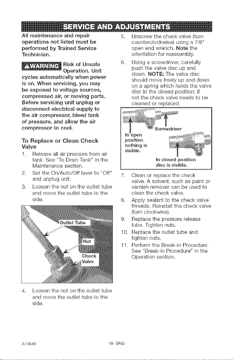
5. Unscrew the check valve (turn
counterclockwise) using a 7/8"
open end wrench. Note the
orientation for reassembly.
6. Using a screwdriver, carefully
push the valve disc up and
down. NOTE: The valve disc
should move freely up and down
on a spring which holds the valve
disc in the closed position; if
not the check valve needs to be
cleaned or replaced.
Screwdriver
In open _,
position ........
nothing is '_
visible.
In closed position
disc is visible.
7. Clean or replace the check
valve. A solvent, such as paint or
varnish remover can be used to
clean the check valve.
8. Apply sealant to the check valve
threads. Reinstall the check valve
(turn clockwise).
9. Replace the pressure release
tube. Tighten nuts.
10. Replace the outlet tube and
tighten nuts.
11. Pedorm the Break-in Procedure.
See "Break-in Procedure" in the
Operation section.
4. Loosen the nut on the outlet tube
and move the outlet tube to the
side.
A13640 16-ENG
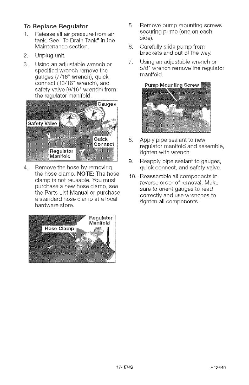
To Replace Regulator
1. Release all air pressure from air
tank. See "To Drain Tank" in the
Maintenance section.
2.
3.
Unplug unit.
Using an adjustable wrench or
specified wrench remove the
gauges (7/!6" wrench), quick
connect (13/16" wrench), and
safety valve (9/16" wrench) from
the regulator manifold.
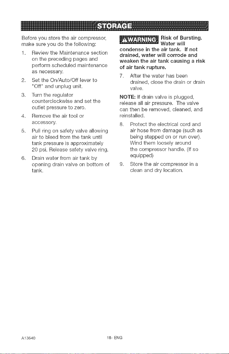
5. Remove pump mounting screws
securing pump (one on each
side).
6. Carefully slide pump from
brackets and out of the way.
7. Using an adjustable wrench or
5/8" wrench remove the regulator
manifold.
4. Remove the hose by removing
the hose clamp. NOTE: The hose
ciamp is not reusable. You must
purchase a new hose clamp, see
the Parts List Manual or purchase
a standard hose clamp at a local
hardware store.
8. Apply pipe sealant to new
regulator manifold and assemble,
tighten with wrench.
9. Reapply pipe sealant to gauges,
quick connect, and safety valve.
10. Reassemble all components in
reverse order of removal. Make
sure to orient gauges to read
correctly and use wrenches to
tighten all components.
Hose Clamp
17-ENG A13640
Before you store the air compressor,
make sure you do the following:
1. Review the Maintenance section
on the preceding pages and
perform scheduled maintenance
as necessary.
2. Set the On/Auto/Off lever to
"Off" and unplug unit.
3. Turn the regulator
counterclockwise and set the
outlet pressure to zero.
4. Remove the air tool or
accessory.
5. Pu!I ring on safety valve allowing
air to bleed from the tank until
tank pressure is approximately
20 psi. Release safety valve ring.
6. Drain water from air tank by
opening drain valve on bottom of
tank.
Risk of Bursting,
Water will
condense in the air tank, If not
drained, water will corrode and
weaken the air tank causing a risk
of air tank rupture,
7. After the water has been
drained, close the drain or drain
valve.
NOTE: If drain valve is plugged,
retease all air pressure. The valve
can then be removed, cleaned, and
reinstalled.
8. Protect the electrica! cord and
air hose from damage (such as
being stepped on or run over).
Wind them loosely around
the compressor handle. (If so
equipped)
9. Store the air compressor in a
clean and dry location.
A13640 18-ENG
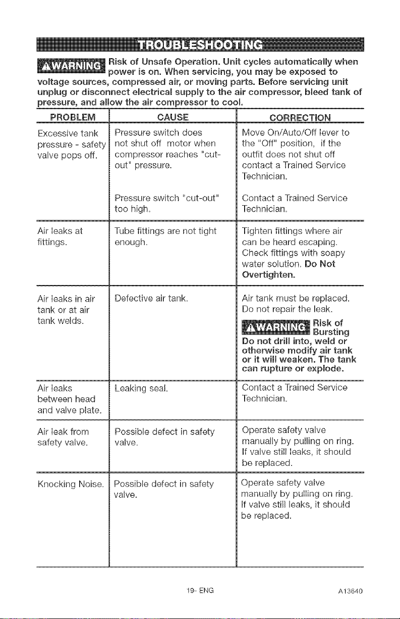
_Risk of Unsafe Operation, Unit cycles automatically when
power is on, When servicing, you may be exposed to
voltage sources, compressed air, or moving parts, Before servicing unit
unplug or disconnect electrical suppmy to the air compressor, bleed tank of
pressure, and allow the air compressor to cool
CORRECTION
PROBLEM
Excessive tank
pressure - safety
valve pops off,
Air [eaks at
fittings=
Air leaks in air
tank or at air
tank welds=
Air leaks
between head
and valve plate,
CAUSE
Pressure switch does
not shut off motor when
compressor reaches "cut-
out" pressure.
Pressure switch "cut-out"
too high,
Tube fittings are not tight
enough,
Defective air tank.
Leaking sea!=
Possible defect in safety
valve,
Possible defect in safety
valve.
Air leak from
safety valve.
Knocking Noise.
Move On/Auto/Off lever to
the "Off" position, if the
outfit does not shut off
contact a Trained Service
Technician.
Contact a Trained Service
Technician.
Tighten fittings where air
can be heard escaping.
Check fittings with soapy
water solution. Do Not
Overtighten,
Air tank must be replaced.
Do not repair the leak.
Do not drill into, weld or
otherwise modify air tank
or it wi[[ weaken, The tank
can rupture or explode,
Contact a Trained Service
Technician,
Operate safety valve
manually by pulling on ring.
if valve still leaks, it should
be replaced.
Operate safety valve
manually by pulling on ring.
if valve still leaks, it shouid
be replaced=
19= ENG A13640
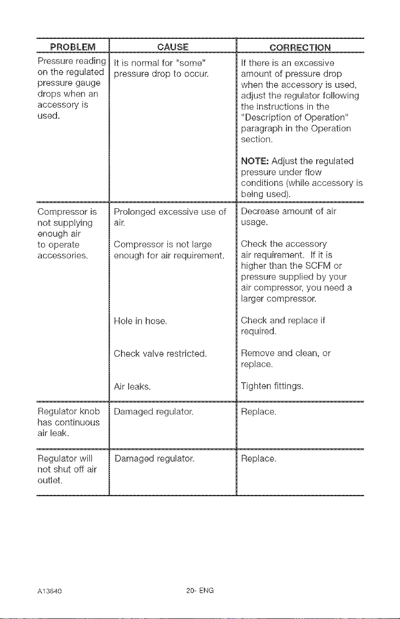
PROBLEM
Pressure reading
on the regulated
pressure gauge
drops when an
accessory is
used.
CAUSE
it is normal for "some"
pressure drop to occur.
Prolonged excessive use of
air.
Compressor is
not supplying
enough air
to operate
accessories.
Regulator knob
has continuous
air leak.
Regulator will
not shut off air
outlet.
Compressor is not large
enough for air requirement.
Hole in hose.
Check valve restricted.
Air leaks.
Damaged regulator.
Damaged regulator.
CORRECTION
if there is an excessive
amount of pressure drop
when the accessory is used,
adjust the regulator following
the instructions in the
"Description of Operation"
paragraph in the Operation
section.
NOTE: Adjust the regulated
pressure under flow
conditions (while accessory is
being used).
Decrease amount of air
usage.
Check the accessory
air requirement. Hfit is
higher than the SCFM or
pressure supplied by your
air compressor, you need a
larger compressor.
Check and replace if
required.
Remove and clean, or
replace.
Tighten fittings.
Replace.
Replace.
A13640 20-ENG
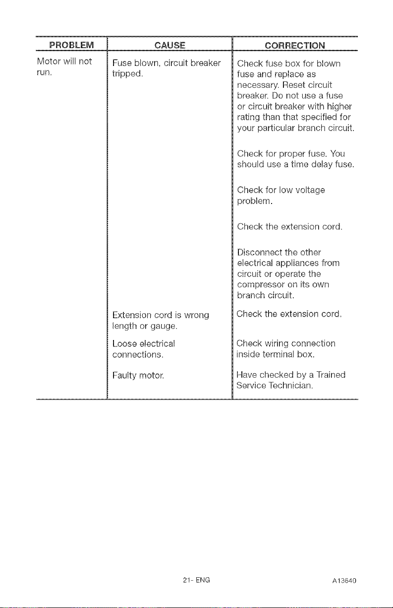
PROBLEM
Motor will not
run.
CAUSE
Fuse blown, circuit breaker
tripped.
Extension cord is wrong
length or gauge.
Loose etectricaJ
connections.
Faulty motor.
CORRECTION
Check fuse box for blown
fuse and repiace as
necessary. Reset circuit
breaker. Do not use a fuse
or circuit breaker with higher
rating than that specified for
your particular branch circuit.
Check for proper fuse. You
should use a time delay fuse.
Check for low voltage
problem.
Check the extension cord.
Disconnect the other
electricaJ appliances from
circuit or operate the
compressor on its own
branch circuit.
Check the extension cord.
Check wiring connection
inside terminal box.
Have checked by a Trained
Service Technician.
21-ENG A13640
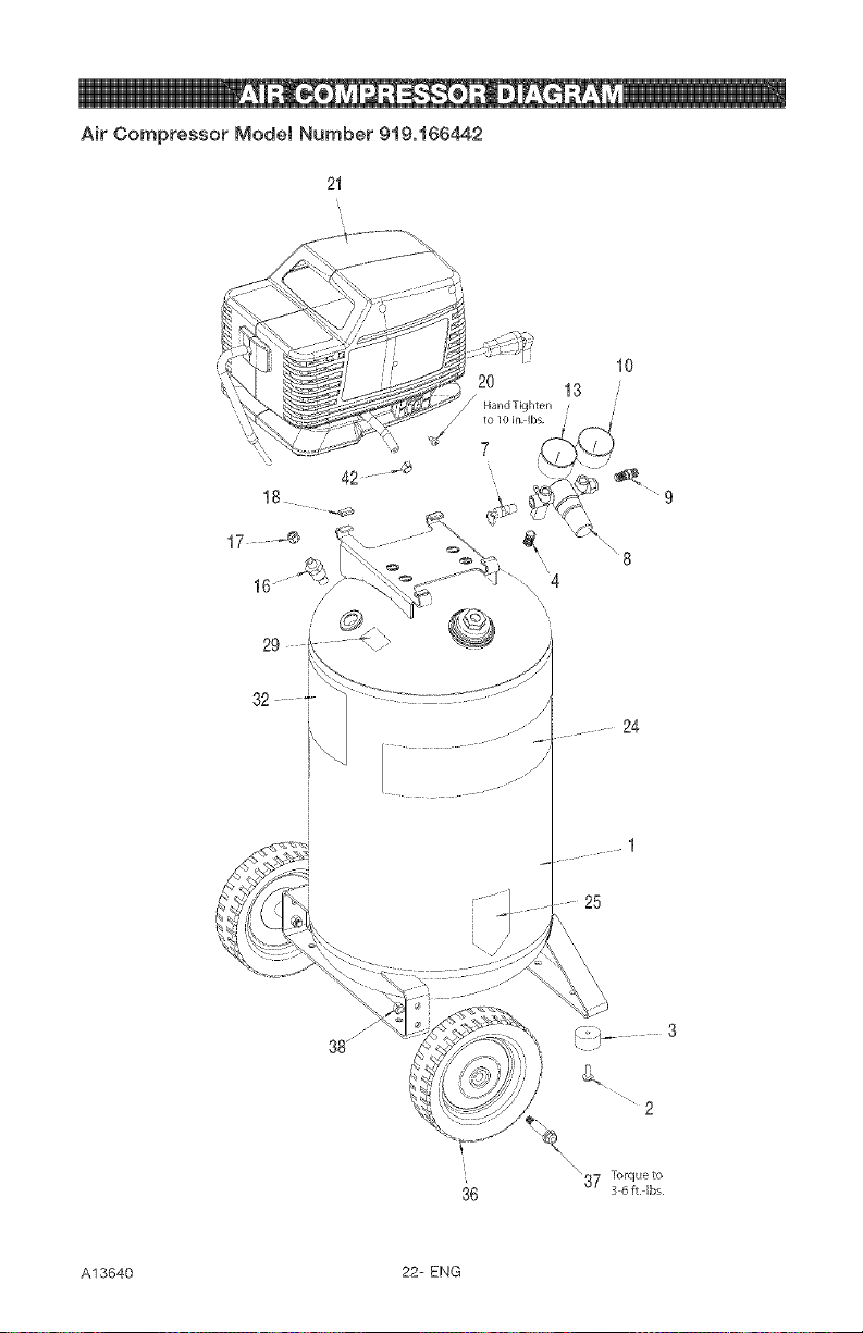
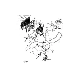
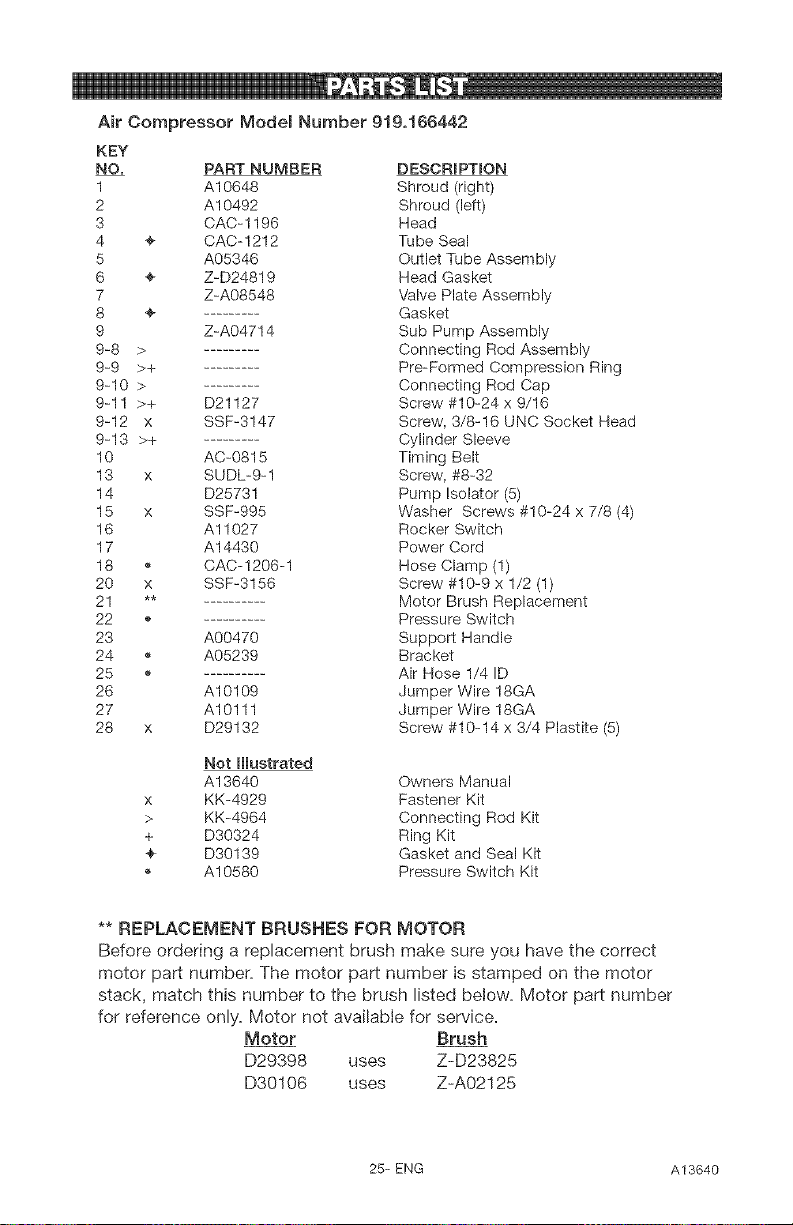
Air Compressor Modet Number 919o166442
lO
13 ,'
//
42
18
17
29
24
1
25
2
"37 Torque to
3 6 ft Ibs
36
A13640 22- ENG
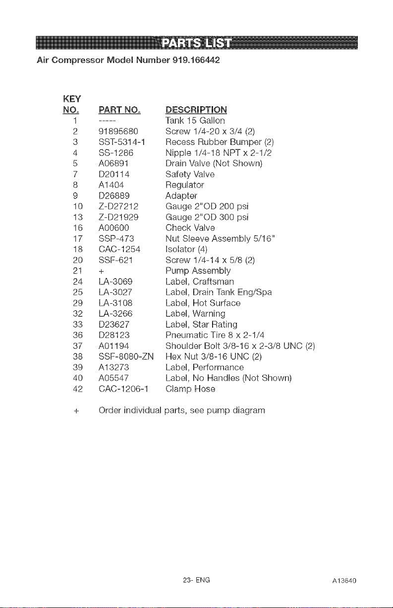
Air Compressor Modet Number 919o166442
KEY
NO, PART NO, DESCRIPTION
1 ..... Tank 15 Gallon
2 91895680 Screw 1/4-20 x 3/4 (2)
3 SST-5314=1 Recess Rubber Bumper (2)
4 SS=1286 Nipple 1/4-18 NPT x 2-1/2
5 A06891 Drain VaNe (Not Shown)
7 D20114 Safety Valve
8 A1404 Regulator
9 D26889 Adapter
10 Z-D27212 Gauge 2"OD 200 psi
13 Z-D21929 Gauge 2"OD 300 psi
16 A00600 Check Valve
17 SSP=473 Nut Sleeve Assembly 5/16"
18 CAC=1254 Isolator (4)
20 SSF-621 Screw 1/4-14 x 5/8 (2)
21 + Pump Assembly
24 LA-3069 Label, Craftsman
25 LA-3027 Label, Drain Tank Eng/Spa
29 LA-3108 Label, Hot Surface
32 LA-3266 Label, Warning
33 D23627 Label, Star Rating
36 D28123 Pneumatic Tire 8 x 2-1/4
37 A01194 Shoulder Bolt 3/8-16 x 2-3/8 UNC (2)
38 SSF=8080=ZN Hex Nut 3/8-16 UNC (2)
39 A13273 Label, Performance
40 A05547 Label, No Handles (Not Shown)
42 CAC=1206=1 Clamp Hose
+ Order individual
parts, see pump diagram
23-ENG A13640
o_
?
m
z
©
28_._
Torqueto be handtighten
to 10 in.dbs,max.
2
Torqueto
30-45in.dbs
13
14
10 /
i
7
6
15
/ Torqueto
49-55in.-Ibs
23
1
/
/'
0
o
S
"o
@
8
@
£
z
B
N
N_
I6
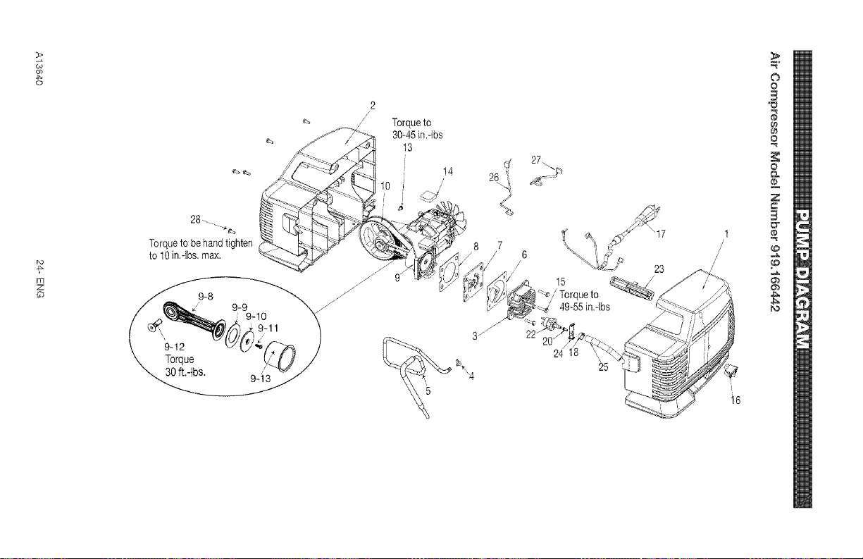
Air Compressor Modem Number 919,166442
KEY
NO. PART NUMBER DESCRIPTION
1 A10648 Shroud (right)
2 A10492 Shroud (left)
3 CAC-1196 Head
4 ÷ CAC-1212 Tube Seal
5 A05346 Outlet Tube Assembly
6 ÷ Z-D24819 Head Gasket
7 Z-A08548 Valve Plate Assembly
8 ÷ Gasket
9 Z-A04714 Sub Pump Assembly
9-8 > Connecting Rod Assembly
9-9 >+ Pre-Formed Compression Ring
9-10 > Connecting Rod Cap
9-11 >+ D21127 Screw #10-24 x 9/16
9-12 x SSF-3147 Screw, 3/8-16 UNC Socket Head
9-13 >+ Cylinder Sleeve
10 AC-0815 Tirning Belt
13 x SUDL-9-1 Screw, #8-32
14 D25731 Pump Lsolator (5)
15 x SSF-995 Washer Screws #10-24 x 7/8 (4)
16 A11027 Rocker Switch
17 A14430 Power Cord
18 e CAC-1206-1 Hose Clamp (1)
20 x SSF-3156 Screw #10-9 x 1/2 (1)
21 ** Motor Brush Replacement
22 e Pressure Switch
23 A00470 Support Handle
24 e A05239 Bracket
25 ,, Air Hose 1/4 ID
26 A10109 Jumper Wire 18GA
27 A10111 Jumper Wire 18GA
28 x D29132 Screw #10-14 x 3/4 Plastite (5)
x
÷
÷
e
Not Illustrated
A13640 Owners Manual
KK-4929 Fastener Kit
KK-4964 Connecting Rod Kit
D30324 Ring Kit
D30139 Gasket and Seal Kit
A10580 Pressure Switch Kit
** REPLACEMENT BRUSHES FOR MOTOR
Before ordering a replacement brush make sure you have the correct
motor part number, The motor part number is stamped on the motor
stack, match this number to the brush listed below, Motor part number
for reference only, Motor not available for service,
Motor Brush
D29398 uses Z-D23825
D30106 uses Z-A02125
25-ENG A13640
GARANTiA TOTAL DE UN ANO DEL OOMPRESOR DE AmRE
Si este compresor de aire Craftsman fallase debido a defectos de materiales
o de fabricaci6n dentro del aMo de su fecha de compra, Sears, a su opciOn,
Io reparara o reemptazara sin costo alguno. Comunfquese con el Centre
de Servicio Sears mas cercano (1-800-4-MY-HOME) para coordinar su
reparaci6n, o devuelva el compresor de aire al lugar donde Io compr6 para
que Io cambien.
Si este compresor de aire se usase con fines comemiales o para alquiier, esta
garantia se aplica s6Io durante Ios primeros noventa dias a partir de su fecha
de compra.
Esta garantia le otorga derechos especfficos y usted podria tener otros
derechos que varian de un estado a otro.
Sears, Roebuck and Co., Dept. 817WA, Hoffman Estates, IL 60179
A13640 26- SP
ii[,
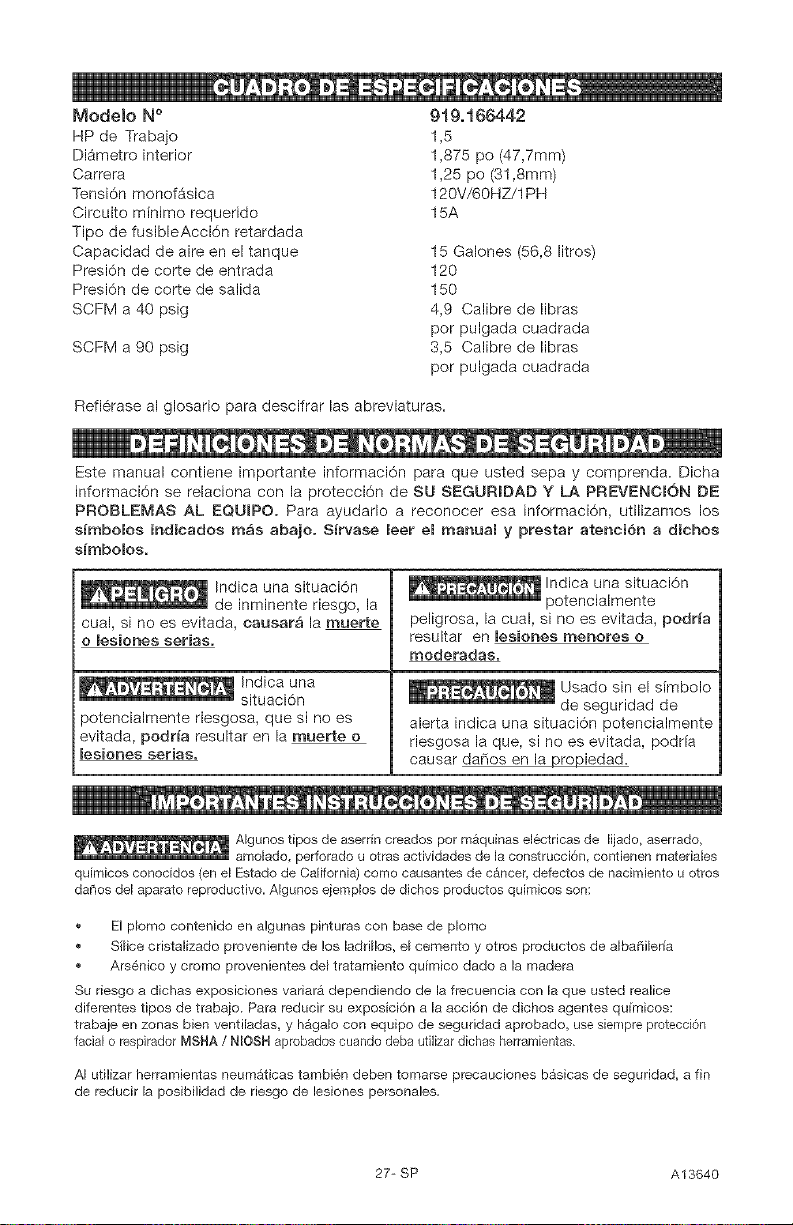
Modelo N °
HP de Trabajo
Di_metro interior
Carrera
Tensi6n monofAsica
Circuito minimo requerido
Tipo de fusibleAcci6n retardada
Capacidad de aire en el tanque
Presi6n de corte de entrada
Presi6n de corte de salida
SCFM a 40 psig
SCFM a 90 psig
919o166442
1,5
1,875 pc (47,7mm)
1,25 po (31,Smm)
120V/60HZ/1PH
15A
15 Galones (56,8 litros)
120
150
4,9 Calibre de libras
por pulgada cuadrada
3,5 Calibre de libras
por pulgada cuadrada
Refi6rase al glosario para descifrar las abreviaturas=
Este manual contiene importante informaci6n para que usted sepa y comprenda. Dicha
informaci6n se relaciona con la protecci6n de SU SEGURIDAD Y LA PREVENCION DE
PROBLEMAS AL EQUIPO. Para ayudarlo a reconocer esa informaci6n, utilizamos los
simbolos indicados m_s abajo. Sirvase leer el manual y prestar atenci6n a dichos
s_mbolos.
Indica una situaci6n
de inminente riesgo, la
cual, si no es evitada, causar_ la muerte
o lesiones serias.
Indica una
situaci6n
potencialmente riesgosa, que si no es
evitada, podria resultar en la muerte o
lesiones serias.
Indica una situaci6n
potencialmente
peligrosa, la cual, si no es evitada, podria
resultar en lesiones menores o
moderadas.
alerta indica una situaci6n potencialmente
riesgosa la que, si no es evitada, podria
causar dafios en la_iedad.
Algunos tipos de aserrin creados por mAquinas electricas de lijado, aserrado,
amolado, perforado u otras actividades de la construcci6n, contienen materiales
quimicos conocidos (en el Estado de California) como causantes de cancer, defectos de nacimiento u otros
dahos del aparato reproductivo. Algunos ejemplos de dichos productos quimicos son:
El p_omo contenido en algunas pinturas con base de p_omo
Si_ice cristalizado proveniente de los ladd_los, e_ cemento y otros pr_ductos de a_bafiileria
Ars_nico y cromo provenientes del tratamiento quimico dado a la madera
Su riesgo a dichas exposiciones variara dependiendo de la frecuencia con la que usted realice
diferentes tipos de trabajo. Para r_ducir su exposici6n a _aacci6n de dichos agentes qufmicos:
trabaje en zonas bien ventiladas, y h_ga_o con equipo de seguridad aprobado, use siempre protecci6n
facial o respirador MSHA / NIOSH aprobados cuando deba utilizar dichas herramientas
A_utilizar herramientas neum_ticas tambiSn deben tomarse precauciones bAsicas de seguddad, a fin
de reducir la posibilidad de riesgo de lesiones personales.
27-SP A13640
, GUARDE ESTAS |NSTRUCCiONES
La operaci6n o el mantenimiento inadecuados de este producto poddan
ocasionar serias lesiones y datios a la propiedad= Lea y comprenda todas las
advertencias e instrucciones de funcionamiento antes de utilizar este equipo=
i _ 0
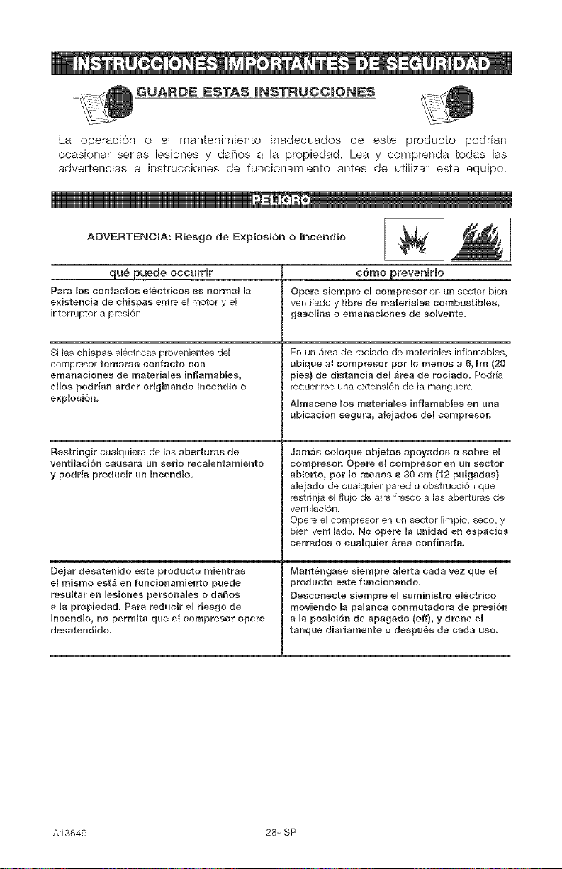
ADVERTENCIA: Riesgo de Explosi6n o Incendio
qu6 puede occurrir
Para los centactos el6ctricos es normal la
e×istencia de chispas entre el motor y el
interruptor a presiSn.
Si las chispas el6ctricas provenientes de_
compresor tomaran contacto con
emanaciones de materiaUes hftamables,
eHos podrian artier originando incendio o
explosi6n.
Restfingir cualquiera de las aberturas de
ventilaoiSn causara un serio recaUentamiento
y podria producir un incendio.
Dejar desatenido este producto mientras
el mismo est_ en funcionamiento puede
resuUtar en lesiones personaUes o daSos
a Ua propiedad. Para redncir el riesgo de
inoendio, no permita qne el compresor opere
desatendido.
c6mo preveniHo
Opere siempre eUcompresor en un sector bien
ventilado y Hbre de materiales combustibles,
gasoUina o emanaciones de soUvente.
En un _rea de rociado de materiales inflamables,
ubiqne al compresor por Io menos a 6,1m (20
pies) de distancia den _rea de rociado. Podria
requerirse una extensi6n de [a manguera.
AUmacene Uos materiaUes infiamables en nna
nbicaci6n segnra, alejados del compresor.
Jam_s coUoqne objetos apoyados o sobre eU
compresor. Opere e8 compresor en nu'_sector
abierto, pot mo menos a 30 cm (12 pnBgadas}
alejado de cua_quier pared u obstrucci6n que
restrinia el fluio de air_ fresco alas aberturas de
ventilaci6n=
Opere el compresor en un sector [impio, seco, y
bien venti_ado= No opere la nnidad en espacios
cerrados o cnaUqnier _rea confinada.
Mant6ngase siempre a{erta carla vez qne e{
prodncto este funcionande.
Deseoneete siempre eU snministro eU6etrico
moviendo Ua paUanca conmutadora de presi6n
a Ua posici6n de apagado (off), y drene eU
tanqae diariamente o despn_s de eada use.
A13640 28= SP
i _ , J
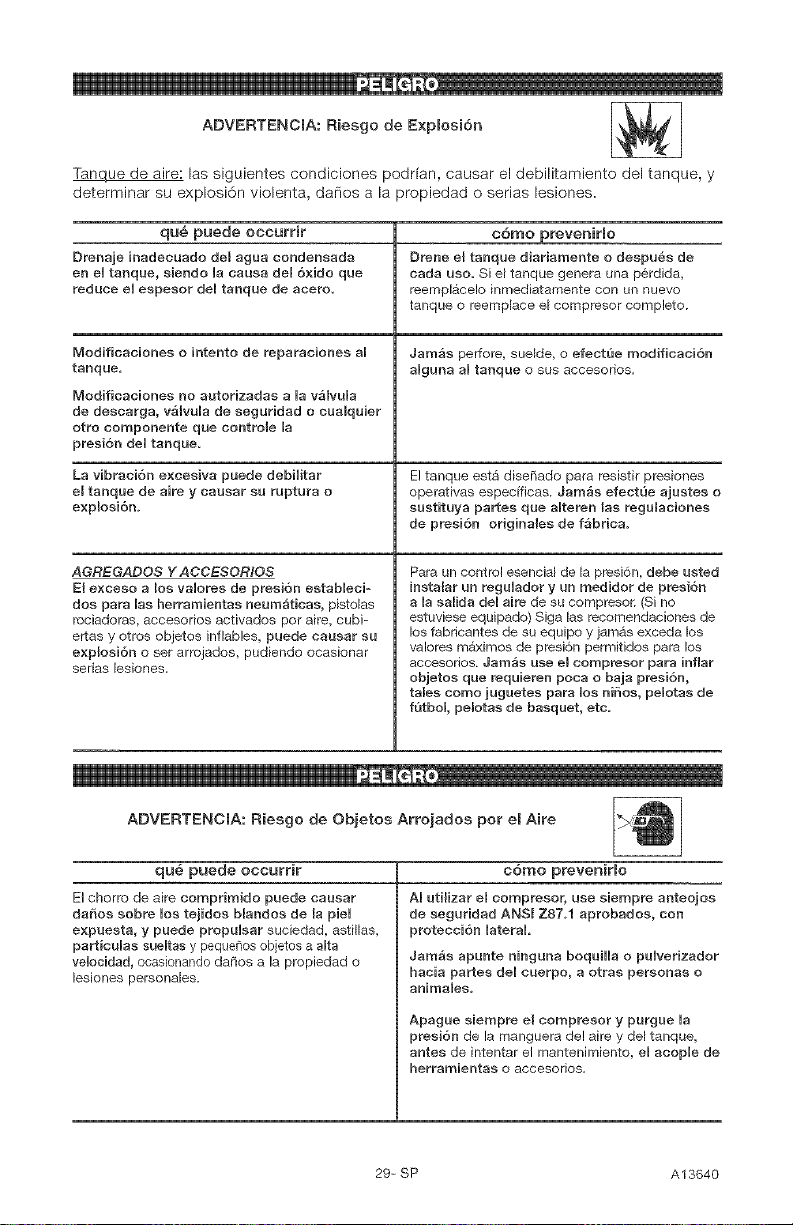
ADVERTENCIA: Riesgo de E×plosi6n I_l
Tanque de aire: las siguientes condiciones podfian, causar el debilitamiento del tanque, y
determinar su explosi6n violenta, danes a la propiedad o serias lesiones.
qu6 puede occurrir c6mo preveniHo
Drenaje inadecuado del agaa condeneada Drene el tanqae diariamente o despa_e de
en el tanqae, eiende la causa del 6×ido que carla use. Si e[ tanque genera una p6rdida,
reduce el espesor del tanque de aeero, t_ernpl&celo inmediatamente con ue nuevo
tanque e r_emp[ace e_compr_sor complete.
Modificaciones o intento de reparacionee al Jam_s peffore, sue_de, o efect_e modificaci6n
tanque, algana al tanque o sus accesorios.
Modifieaeiones no autorizadas a Uav_lvula
de descarga, v_lvuUa de seguridad o eaaiquier
otto componente que controle la
preei6n deU tanqae.
La vibraci6n e×ceeiva paede debiHtar El tanque estA dise_ado para r_sistir presiones
el tanqae de aire y causar sa raptura o operativas especificas. Jamgs efectQe ajuetes o
explosi6n, saetituya partes que aUteren las regalaciones
de presi6n originalee de f_brica.
AGREGADOS Y AOOESOR,_OS
El excess a los vaUores de preei6n eetabUeci-
dos para Uasherrarnientas neurnaticas, pistolas
rociadoras, accesodos activados per aire, cubi-
ertas y otr_s objetos inflables, puede causar sa
e×plosi6n o set arrojados, pudiendo ocasionar
serias [esiones.
Para un control esencial de la presi6n, debe usted
instaiar an regaUador y an medider de preei6n
a la salida del aire de eu compresoE (Si no
estuviese equipado) Siga las recomendaciones de
_os fabricantes de su equipo y jamAs exceda los
valores m&ximos de presi6n permitidos para los
accesorios. Jarn_s use el eompreeor para inflar
objetos que reqaieren poca o baja presi6n,
tales come jugaetee para UoenJSos, peUotas de
f,3tboU, pesetas de baeqaet, etc.
ADVERTENCIA: Riesgo de Objetos Arrojados per el Aire
qu6 puede occurrir c6mo preveniHo
El chor_o de aire comprimido puede causar
daffos sobre Uostejidos blandos de la pieU
e×puesta, y puede prepuUsar suciedad, astit_as,
part_cuUas saeUtas y peque_es ebjetos a a_ta
ve_ocidad, ocasionando da[tos a la propiedad o
lesiones personales.
AI utilizar el compresor, use siempre anteojos
de segaridad ANSI Z87.1 aprobados, con
protecci6n _ateraL
Jam_s apunte ninguna boqaiHa o pa_verizador
hacia partee de_ cuerpo, a otrae personae o
animates.
Apagae siempre el eompresor y purgue _a
presi6n de la manguera de! aire y del tanque,
antes de intentat el mantenimiento, el acop_e de
herrarnientae o accesorios.
29-SP A13640
n
is
ADVERTENCIA: Riesgo de Descarga ER_ctrica
qu6 puede occurrir c6mo preveniHo
Su cornpresor de aire est_ accionado pot Jam&s opere el compresor a la intemperie
e_ectricidad= Como cualquier otro dispositivo cuando est& Iloviendo o en condiciones de
e!Sctrico impulsado el6ctricamente, si no se Uo humedad=Nunca opere el compresor sin sue
utiliza adecuadamente, podr_a causarle una defensas o sue cubiertas rernovidas o
desearga eU_ctriea= da_adas.
Las reparaciones intentadas por personaU no
calificado podrian ocasionar serias Uesionee o
la muerte per eiectrocuei6m
CONEXION A T1ERRA: Oejar de proveer una
adecuada cone×i6n a tierra a este produeto
podria ocaeionar lesionee serias o Uamuerte
pot eUectrocuci6n. Ver instrucciones para la
puesta a tierra.
Cualquier cone×i6e el_ctrica o reparaci6n
requerida per este predueto debe set
efectuada per personaU autorizado de Uoe
servicentros de acuerdo a los c6digos el6ctricos
nacionales y locale&
AsegQrese que eUcireuito eU_.etrico a_cual est_
conectado el compresor_ suministra apropiada
conexi6n a tierra, tensi6n correcta y una
adecuada protecci6n de fusibUee.
ADVERTENCIA: Riesgo de Inhalaci6n
qu6 puede occurrir c6rno preveniHo
El aire cornprimido proveniente del compresor
no es sano para respirar. El chorro de aire
puede contener mon6×ido de carbono,
vapores t6×icos o particuUas s61idas
provenientes del tanque. La inhaUaei6n de
dichos contaminantes puede Hegar a causar
serias lesiones o Uamuerte.
El rociade de materiales tales come pintura,
solventes, removedores de pintura, insecticidas,
mata hierbas, contienen emanaeiones da_inas
y venenosas.
El aire obtenido directamente de_ compresor
jarnAs deber_ set utilizado para proveer aire
para consume humano. Para poder utilizar el
aire producido pot este compr_sor y hacerlo
r_spiraMe, deber_n instalarse un filtro
adecuado y un equipo de seguridad
intercaUado. Los filtros interca_ados tanto come
eUequipo de eeguridad utilizado en conjunto
con e_compr÷sor, deber_n ser capaces de
procesar e{ tratarniento deU aire de acuerdo a
todos Ins e6digns UocaUes y federaUes, previo
8_ eensumo humano,
Trabaje en un _rea con buena ventilaci6n
cruzada. Lea y siga las instruccionee de
seguridad provistas en el rgtulo o en los datos
de _as hojas de seguridad de[ material que est_
pu_verizando. Use e_ respiradnr aprobado
N_OSH/MSHA designado para utilizarse con su
aplicacion especifica=
A13640 30-SP
_0
ADVERTENCmA: Riesgo de Quemaduras
qu_ puede occurrir
Tocar eUmetaU e×puesto tal como el cabezal
de! compresor o los tubos de salida de! escape,
puede ocaeionarIe serias quemaduras.
c6mo preveniHo
Jam_s toque partes de metal e×pueetas en e_
compresor dur_nte o inmediatamente despu6s
de la operaci6n, eUcompresor permaeecer_
caliente pot vados minutos luego de la
operaci6n.
No Uo cubra con fundas protectoras o #_tente
eJ maoteuimiento haeta que la unidad haya
alcanzado su enfriamiento.
ADVERTENCIA: Riesgo de Partes M6vHes
qu_ puede occurrir c6mo preveniHo
Partee moviblee tales como _a polea, el volante Nunca opere el compresor sin eus defensas o
y la corr_a poddao set Uacausa de eeriae sus cubiertas removidas o daFiadas.
leeiones si elias entraran en contacto con usted
o sus ropas.
Enteotar operar el compresor con sue par- Cua_qaier r_paraciSn requerida pot este
tes da_adas o faUtantee, o la reparaci6n deU producto debe set efectuada pot personal
compresor con eus proteccioues removidas, autorizado de Uos serviceu'_tros.
puede expooeHo a ueted a partee movibles,
que poddan resultar en Uesionee serias,
ADVERTENCIA: Riesgo de Cabala 'J',
q,u_ puede occurrir
Un compr÷sor port_til puede caerse de la
mesa, e! banco de trabajo o del techo da_ando
al compresor y pudiendo reeuUtar en serias
lesiones o Uamuerte deU operador_
c6mo prevenirlo
Opere siempre el compresor en una posici6n
estaMe y segura a fin de prevenir el movimiento
accidenta_ de la un{dad. Jam_e opere eU
compresor sobre un techo u otra poeiciSn
elevada, UtiUice mangueras adicionaUee de
aire para aUcanzar posicionee aUtas.
31-SP A13640
i
ADVERTENOIA: Riesgo de Sepias Lesiones o DaSos a la Propiedad al
Transportar el ¢ornpresor
(Fuego, hhaUaci6n, daSo a la superficie de vehicuUos)
qu_ puede occurrir c6mo prevenirlo
EUaceite puede derramarse y ello podfia Deposite el cornpreeor eobre aria affornbriHa
resultar en serias fesiones o la muerte debido al protectora cuando Uotransporte, a fin de
riesgo de incendio o inha_aci6n_ El derrame de proteger a_ vehiculo de p6rdidas por goteo,
aceite daSa affombras, pinturas u otras Retire e_ compr_sor del vehicu_o inmediatamente
superficies de vehicu_os o remolques, despu6s de sa arribo a] destino.
° _ I
ADVERTENCIA: Riesgo de Operaci6n Lasegura
q u6 puede occurrir
La operacion insegara de su compresor de air_
pod_ia oeasienaHe serias lesiones o Uamae_te
a asted a otros,
c6mo preveniHo
Revise y comprenda todas las instrucciones y
adve_teneias contenidas en este manual
FamiUiaricese con los m_todos de operaci6n y
controU de! compresor de air_.
Mantenga libre Ja zona de operaciones
de persona alguna, animales dom6sticos y
obst_cu_os_
Mantenga aUejados a los niSos del compresor
de aire en todo mornento.
No ope_e eUproducto eaando se eneuentre
fatigado o bajo UainfBaeneia deU aUcohoU o
drogas, Est_ alerta en redo momente,
Jamge aUtere los elernentos de seguridad de
este producto.
Equipe la zona de operaciones con ue
e×tinguidor de fuego,
No opere Uam_quiea si _eta tiene pastes
faltantes, rotas o no autorizadas,
CONSERVAR ESTAS mNSTRUCCmONES
A13640 32- SP
FamiliaHcese con los siguientes t6rminos,
antes de operar la unidad:
CFM: (Cubic feet per minute) Pies cObicos
per minute.
SCFM: (Stardard cubic feet per minute)
Pies cObicos estandar per minute; una
unidad de medida que permite medir la
cantidad de entrega de aire.
PSIG: (Pound per square inch) Libras per
pulgada cuadrada.
C6digo de eertificaei6n: Los productos
que usan una o mas de las siguientes
marcas: UL, CUL, ETL, CETL, han side
evaluados per OSHA, laboratories
independientes certificados en seguridad,
y re0nen los est_ndares suscriptos per los
laboratories dedicados a la certificaci6n
de la seguridad.
Presi6n minima de eorte: Cuando el
motor est_ apagado, la presi6n del tanque
de aire baja a medida que usted continLia
usando su accesorio. Cuando la presi6n
del tanque baja al valor fijado en f_brica
come punto bajo, el motor volvera a
arrancar autom_ticamente. La presion
baja a la cual el motor arranca
autom_ticamente, se llama presi6n
"mfnima de corte".
Presi6n m;_xima de eorte: Cuando un
compresor de aire se enciende y
comienza a funcionar, la presion de
aire en el tanque comienza a aumental:
Aumenta hasta un valor de presi6n alto
fijado en f_brica antes de que el motor
autom_ticamente se apague protegiendo
a su tanque de aire de presiones mAs
altas que su capacidad. La presi6n alta a
la cual el motor se apaga se llama presi6n
"maxima de corte"+
Ramal: Circuito el6ctrico que transporta
electricidad desde el panel de control
hasta el tomacorriente.
Esta unidad es suficiente para abastecer de energia electrica a los siguientes accesorios. Estos
se encuentran disponibles a trav_s del catAIogo para herramientas el6ctricas y manuales, en
cualquiera de los comercios que mantiene la ltnea completa de SEARS.
Aecesorioe + Lubricadores de niebla de aceite
+ Filtro en Ifnea + Manguera de aire: 1/4 plug., 3/8 plug.
+ Entrada de aire a neum_ticos o 1/2 plug. D.L en varias medidas
+ Juegos de conectores r_pidos (varies
tamados) Refi6rase al grafico de selecci6n ubicado
+ Reguladores de presi6n de aire sobre la unidad, para elegir el tipo de
herramienta que esta unidad es capaz de
hacer funcionar.
Esta bomba compresora de aire es capaz
de funcionar continuamente, sin embargo
para prolongar la vida Otil de su compresor
de aire se recomienda mantener un ciclo
promedio de servicio que oscile entre el
50% y el 75%; ello significa que la bomba
compresora no debena trabajar m_s de 30 a
45 minutes per hera.
33-SP A13640
Desempaque
1. Extraiga la unidad de su caja
y descarte todas las partes de
embalaje.
come PREPARAR LA UN[DAD 2. AsegOrese de que el tomacorriente
Ubicaci6n de[ compresor de aire
Ubique al compresor de aire en una
zona limpia, seca y bien ventilada. El
compresor de aire debe estar instalado -
per Io menos - a una distancia no menor
de 12 plug. (30 cm) de la pared u otras
obstrucciones que pudiesen interferir
con el flujo del aire. La bomba del
compresor de aire y su carcasa hart side
diseffadas para permitir su enfriamiento
adecuado. Las aberturas de ventilaci6n
del compresor resultan - entonces -
necesarias para el mantenimiento de una
adecuada temperatura de funcionamiento.
No coloque g6neros o contenedores,
encima, ni en las proximidades de dichas
aberturas.
INSTRUCCIONES PARA CONECTAR
A TIERRA
_ RIESGO DE CHEQUE
ELECTRICO. Ante
[a eventua[idad de un eortoeircuito, [a
cone×i6n a tierra reduce eBriesgo de
e[ectrecuci6n proveyendo un conductor
de escape para [a corriente em_ctrica.
Este cornpresor de abe debe estar
adecuadamente eoneetado a tierra.
El compresor port_til de aire est&
equipado con un cable que tiene un
conductor destinado a tierra, con una
espiga apropiada para su conexi6n (vet
las siguientes ilustraciones). El enchufe
debe set utilizado con un toma corriente
que haya side instalado y conectado a
tierra de acuerdo a todos los c6digos y
ordenanzas locales.
El cable que acompafia a esta unidad
tiene una espiga para conexi6n a
tierra. Esta DEBE ser utilizada con un
tomacorriente conectado a tierra.
[MPORTANTE: El tomacorriente que sera
utilizado deber_ haber side conectado
a tierra conforme a todos los c6digos
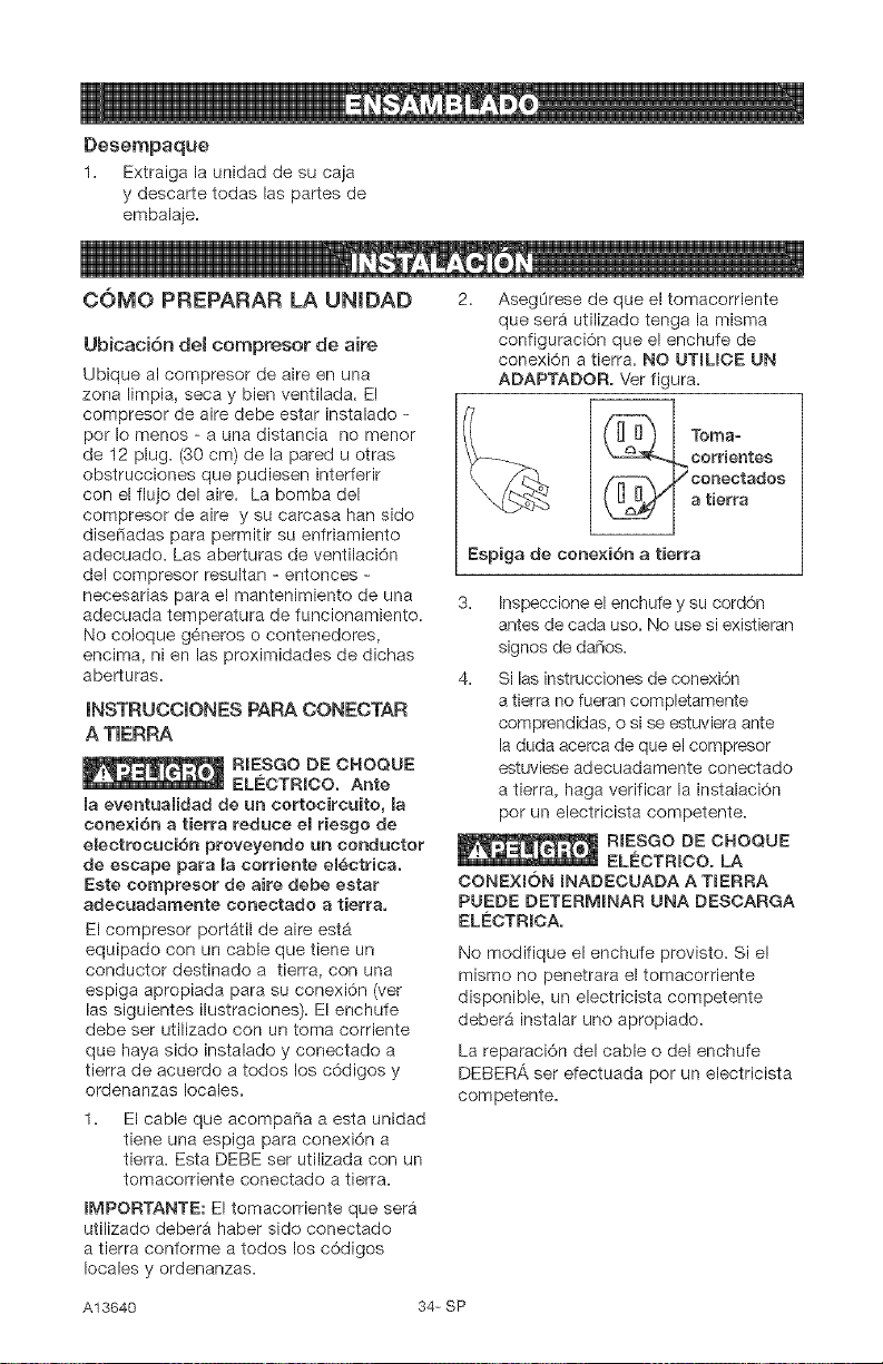
locales y ordenanzas.
que sera utilizado tenga la misma
configuraci6n que el enchufe de
conexi6n a tierra. NO UTlUCE UN
ADAPTADOR. Ver figura.
Tomao
eorr[entes
conectados
a tierra
Espiga de eone×i6n a tierra
3. Inspeccione el enchufe y su cord6n
antes de cada use. No use si existieran
signos de daffos.
4. Si las instrucciones de conexion
a tierra no fueran completamente
comprendidas, o si se estuviera ante
la duda acerca de que el compresor
estuviese adecuadamente conectado
a tierra, haga verificar la instalaci6n
per un electricista competente.
_ RIESGO DE CHEQUE
ELECTRICO. LA
CONEXION INADECUADA A TIERRA
PUEDE DETERMINAR UNA DESCARGA
ELECTRICA,
No modifique el enchufe provisto. Si el
mismo no penetrara el tomacorriente
disponible, un electricista competente
deber_ instalar uno apropiado.
La reparaci6n del cable odel enchufe
DEBERA ser efectuada per un electricista
com petente.
A13640 34- SP
Cables de extensi6n em_ctdca
No se recomienda la utilizaci6n de cables
de extensi6n el6ctrica. El uso de cables
de extensi6n el6ctrica originar_ una
caida de tensi6n, Io que determinar_ una
p6rdida de potencia del motor as[ come
su recalentamiento. En lugar de utilizar un
cable de extensi6n el6ctrica, incremente
el alcance de la manguera de aire dentro
de la zona de trabajo, afiadi6ndole otro
largo de manguera a su extremo. Conecte
los largos adicionales de manguera de
acuerdo a su necesidad.
Si - no obstante - debe utilizarse una
extensi6n de cable, asegOrese de que:
e La extensi6n el6ctrica de 3
conductores, tenga un enchufe de
conexi6n a tierra de 3 hojas, y que
exista un recept_culo que acepte el
enchufe del producto.
e Est6 en buenas condiciones.
,, No mas largo que 15,2 m (50 pies).
e Calibre 12 (AWG) o mayor. (La medida
de los cables se incrementa a medida
que su nOmero ordinal decrece. 10 y
8 AWG pueden ser usados tambi_n.
NO USE 14 NI 16 AWG).
Protecci6n del voJtaje y del circuito
Acerca del voltaje y la mfnima cantidad de
circuitos requeridos, refi6rase al cuadro de
especificaciones.
compresores de aire pueden set
operades enurl eireuito de 15 A,
siempre que se cumplan las siguientes
eondiciones:
1. Que el voltaje suministrado a trav6s de
los ramales del circuito sea de 15 A.
2. Que el circuito no sea utilizado para
alimentar ninguna otra necesidad
el6ctrica.
3. Que los cables de extension cumplan
con las especificaciones.
4. El circuito cuenta con un disyuntor de
15 amperios o un fusible de acci6n
retardada de 15 amperios. NOTA: Si
el compresor est,. conectado a un
circuito protegido per fusibles, use
s61o fusibles de acci6n retardada.
Los fusibles de acci6n retardada
deben estar marcados con la letra
"D" en Canad_ y "T" en EE.UU.
Si cualquiera de las condiciones
enumeradas no pudiese ser cumplida, o si
el funcionamiento del compresor causara
reiteradas interrupciones de la energia con
la que se Io alimenta, podria set necesario
operar al mismo desde un circuito de 20
A. Para ello no sera necesario cambiar su
cable de limentaci6n.
35-SP A13640
Conozca su compresor de aire
LEA ESTE MANUAL DEL PROPIETARiO Y SUS NORMAS DE SEGURiDAD ANTES DE
OPERAR LA UNIDAD. Compare las ilustraciones contra su unidad a fin de familiarizarse
con la ubicaci6n de los distintos controles y regulaciones. Conserve este manual para
referencias futuras.
Descdpci6n de operaciones
Familiaricese con estos controles antes de
operar la unidad.
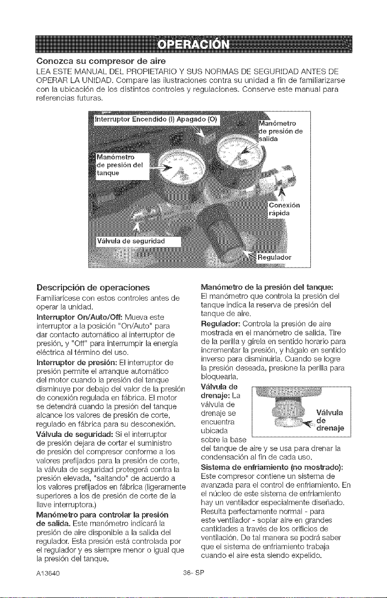
Interruptor On/Auto/Off: Mueva este
interruptor a la posici6n "On/Auto" para
dar contacto automatico al interruptor de
presbn, y "Off" para interrumpir la energ[a
el6ctrica al t6rmino del uso.
Interruptor de presiSn: El interruptor de
presbn permite el arranque autom_tico
del motor cuando la presbn del tanque
disminuye pot debajo del valor de la presi6n
de conexi6n regulada en f_brica. El motor
se detendr_ cuando la presi6n del tanque
alcance los valores de presi6n de core,
regulado en fabrica para su desconexbn.
V_Rvulade seguridad: Si el interruptor
de presbn dejara de cortar el suministro
de presbn del compresor conforme a los
valores prefijados para la presbn de core,
la v_lvula de seguridad proteger_ contra la
presi6n elevada, "saltando" de acuerdo a
los valores prefijados en fabrica (ligeramente
superiores a los de presi6n de corte de la
Ilave interruptora.)
Man6metro para controlar BapresiSn
de salida. Este man6metro indicar_ la
presbn de aire disponible a la salida del
regulador. Esta presi6n esta controlada pot
el regulador yes siempre menor o igual que
la presi6n del tanque.
Man6metro de la presi6n deBtanque:
El man6metro que controla la presi6n del
tanque indica la reserva de presi6n del
tanque de aire.
Regulador: Controla la presi6n de aire
mostrada en el man6metro de salida. Tire
de la perilla y girela en sentido horatio para
incrementar la presi6n, y h_galo en sentido
inverso para disminuirla. Cuando se Iogre
la presi6n deseada, presione la perilla para
bloquearla.
V_Rvula de
drenaje: La
v_lvula de
drenaje se
encuentra
ubicada
sobre la base
del tanque de aire y se usa para drenar la
condensaci6n al fin de cada uso.
Sistema de enfriamiento {no mostrado):
Este compresor contiene un sistema de
avanzada para el control de enfriamiento. En
el nOcleo de este sistema de enfriamiento
hay un ventilador especialmente disefiado.
Resulta perfectamente normal - para
este ventilador - soplar aire en grandes
cantidades a trav6s de los orificios de
ventilaci6n. De tal manera se podr_ saber
que el sistema de enfriamiento trabaja
cuando el aire esta siendo expelido.
A13640 36- SP
Bornba de compresi6n del aire {no
mosttada}: Comprime el aire dentro del
tanque. El aire de trabajo no se encuentra
disponible hasta que el compresor haya
alcanzado a Ilenar el tanque hasta un nivel
de presi6n per encima del requerido para la
salida del aire.
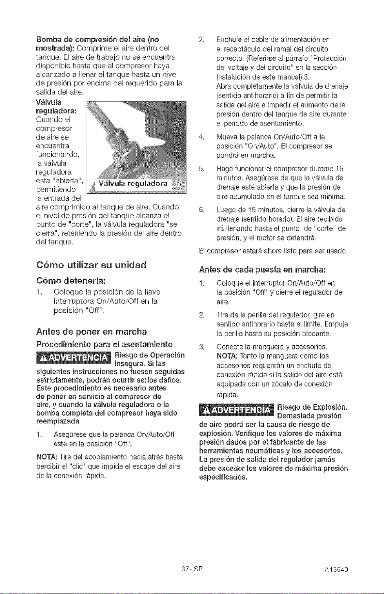
VaRvula
reguBadora:
Cuando el
compreeor
de aire se
encuentra
funcionando,
la v_lvula
reguladora
esta "abieRa", V_Bvula
permitiendo
la entrada del
aire comprimido al tanque de aire. Cuando
el nivel de presi6n del tanque alcanza el
punto de "coRe", la v_lvula reguladora "se
cierra", reteniendo la presi6n del aire dentro
del tanque.
C6mo utimizar su unidad
C6rno detenerla:
1. Coloque la posici6n de la Ilave
interruptora On/Auto/Off en la
posici6n "Off".
Antes de poner en rnarcha
Procedimiento para e[ asentamiento
Rieego de Operaci6n
Insegura. S] las
siguientes instrueciones no fueeen seguidas
eetrictamente, podr_n ocurfir serios da5os.
Este procedimiento es necesario antes
de poner en eervicio aUcompreeor de
aire, y cuando Uav_UvuUareguladora o la
bomba compUeta deUcompreeor haya eido
reempUazada
1. AsegOrese que la palanca On/Auto/Off
este en la posici6n "Off".
NOTA: Tire del acoplamiento hacia atras hasta
percibir el "clic" que impide el escape del aire
de la conexi6n r_pida.
2. Enchufe el cable de alimentaci6n en
el recept&culo del ramal del circuito
correcto. (Referirse al parrafo "Protecci6n
del voltaje y del circuito" en la secci6n
Instalaci6n de este manual).3.
Abra completamente la valvula de drenaje
(sentido antihorario) a fin de permitir la
salida del aire e impedir el aumento de la
presi6n dentro del tanque de aire durante
el periodo de asentamiento.
4. Mueva la palanca On/Auto/Off a la
posici6n "On/Auto". El compresor se
pondr& en marcha.
5. Haga funcionar el compresor durante 15
minutos. AsegQrese de que la v_tvula de
drenaje est6 abieRa y que la presi6n de
aire acumulado en el tanque sea minima.
6. Luego de 15 minutos, cierre la v&lvula de
drenaje (sentido horatio). El aire recibido
ir_ Ilenando basra el punto de "coRe" de
presi6n, y el motor se detendra.
El compresor estar_ ahora Iisto para ser usado.
Antes de cada puesta en marcha:
1. Coloque et interruptor On/Auto/Off en
la posici6n "Off" y cierre el regulador de
aire.
2. Tire de la perilla del regulador, gire en
sentide antihorario hasta el limite. Empuje
la perilla hasta su posicidn b!ocante.
3. Conecte la manguera y accesorios.
NOTA: Tanto la manguera como los
accesorios requerir_n un enchufe de
conexi6n rapida sila salida del aire esta
equipada con un z6ca!o de conexi6n
r_pida.
Riesgo de E×ploei6n.
Demasiada preei6n
de aire podr_ set la cauea de rieego de
e×plosJ6n. Verifique los valores de m_×ima
presi6n dados pot el fabricante de lae
herramientae neum_ticas y los aeceeorios.
La presi6n de ealida del regulador ]am_e
debe e×ceder los valores de m_×ima presi6n
eepecificados.
37-SP A13640
Responsabilidades dem ciiente
Antes
de _iariamente
cada ,_luegede
3ada use
use
ierifique la valvula de seguridad @
::)renaje del tanque @
Riesgo de
Operaci6n
mnsegura. Cuando se reamizan trabajes
de mantenimiento, usted puede estar
expuesto a fuentes de voltaje, aire
comprirnido o piezas en movimiento.
Pueden oeurrir lesiones personales.
Antes de reaHzar cualquier trabajo
de mantenimiente o reparaci6n,
desconecte la fuente de energia del
compresor y purgue toda la presi6n
de aire.
NOTA: Vea en la secci6n Operaci6n la
ubicaci6n de los controles.
C6mo verificar mav_mvula de
seguridad
Riesgo de
Explosi6n. Si
la v_Bvula de seguridad no trabaja
adecuadamente, erie podr_ deterrninar
la sobrepresiSn del tanque, ereando el
riesgo de su ruptura o expRosi6n.
1. Antes de poner en marcha el
motor, tire del anillo de la v_lvula
de seguridad para confirmar
la seguridad de que la misma
opera libremente, si la vAIvula
quedase trabada o no trabajara
comodamente, deber_ set
reemplazada per el mismo tipo de
v_lvula.
C6mo drenar eB tanque
1. Coloque la palanca On/Auto/Off en
la posiciSn "Off".
2. Tire de la perilla del regulador y gire
en sentido contrario alas agujas
de reloj para establecer la salida de
presi6n en cero.
3. Remueva la herramienta neumAtica
o el accesorio.
4. Tire del aro de la valvula de
seguridad dejando purgar el aire
del tanque hasta que este reduzca
su presi6n aproximadamente a 20
PSI. Suelte el are de la v_lvula de
seguridad.
5. Drene el agua contenida en el
tanque de aire, abriendo la vAIvula
de drenaje ubicada en la base del
tanque (en sentido contrario alas
agujas de reloj).
Riesgo de
Explosi6n.
Dentro del tanque se producir_
eondensaei6n de agua. Si no drena, eB
agua Io eorroer& y debHitar& eausando
un riesgo de ruptura del tanque de
aire.
6. Una vez drenada el agua, cierre
la v#Jvula de drenaje (girando en
sentido horatio). Ahora el compresor
de aire podr_ set guardado.
NOTA: Si la vAIvula de drenaje fuera del
tipo enchufe, elimine toda la presion
de aire. La v_lvula podr_ entonces
ser extraida, limpiada y finalmente
reinstalada.
A13640 38-SP
Todo tipo de mantenimiento y
operaciones de reparaci6n no
mencionados, deber_n set efectuados
por personal t6cnico especializado.
Riesgo de
Operaci6n
Insegura: La unidad arranca
autom&ticamente cuando est_
enchufada. ABhacer el mantenimiento,
el operador puede quedar e×puesto
a fuentes de corriente y de aire
comprimido o a piezas movibles.
Antes de intentar hacer reparaciones,
desconectar emcompresor del
tomacorriente, drenar Bapresi6n de
aire deRtanque y esperar a que eR
compresor se enfr_e.
Para reempmazar o Hmpiar la
vatvula de retenci6n
1. Libere toda la presi6n del tanque de
aire. Vea "C6mo Drenar el Tanque"
en la secci6n Mantenimiento.
2. Apagar la unidad colocando el
interruptor en On/Auto/Off en "Off".
3. Extraigala mangueraremoviendola
abrazaderaque lasujeta. NOTA: La
abrazaderade la manguerano es
reutilizable.Deberacomprarse una nueva
abrazadera,ver la Iista de partes del manual
o compre una abrazaderaest_ndar en
cualquiercomercio de ferretefia.
V_lvula
reguladora
Desenrosque la v_lvula de retencion
gir_ndola hacia la izquierda usando
una Ilave de boca de 7/8 plug.
(22 mm). Tome nota de la
orientaci6n para volverla a
ensamblar.
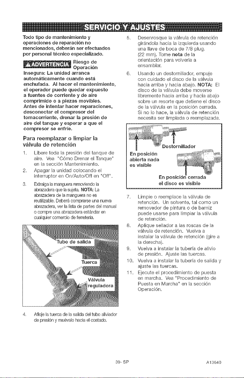
Usando un destornillador, empuje
con cuidado el disco de la valvula
hacia arriba y hacia abajo. NOT,&: El
disco de la v_lvula debe moverse
libremente hacia arriba y hacia abajo
sobre un resorte que detiene el disco
de la v_lvula en la posici6n cerrada.
Si no Io hace, la v_lvula de retenci6n
necesita ser limpiada o reemplazada.
En posici6n _
abierta nada
es visible
En posic
el disco es visible
7. Limpie o reemplace la v_lvula de
retenci6n. Un solvente, tal como un
removedor de pintura o de bamiz
puede usarse para limpiar la v_lvula
de retenci6n.
8. Aplique sellador alas roscas de la
v_lvula de retenci6n. Vuelva a
instalar la valvula de retenci6n (gire a
la derecha).
9. Vuelva a instalar la tubeda de alivio
de presi6n. Ajuste las tuemas.
10. Vuelva a instalar la tubeda de salida y
ajuste las tuercas.
11. Ejecute el procedimiento de puesta
en marcha. Vea "Procedimiento de
Puesta en Marcha" en la secci6n
Operaci6n.
4. Afloje latuerca de la salida del tubo aliviador
de presi6ny muevato hacia el costado.
39_ SP A13640
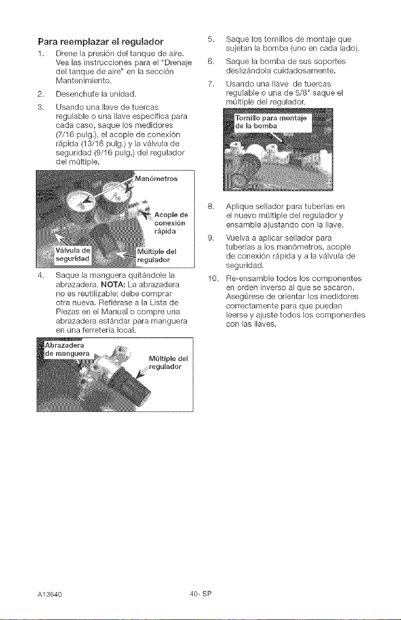
Para reempBazar el regulador 5.
1. Drene la presi6n del tanque de aire.
Vea las instrucciones para el "Drenaje 6.
del tanque de aire" en la secci6n
Mantenimiento. 7.
2.
3.
Desenchufe la unidad.
Usando una Ilave de tuercas
regulable o una Ilave espec[fica para
cada caso, saque los medidores
(7/16 pulg.), el acople de conexi6n
r_pida (13/16 pulg.) y la v_lvula de
seguridad (9/16 pulg.) del regulador
del mOltiple.
Man6metros
Saque la manguera quitandole la
abrazadera. NOTA: La abrazadera
no es reutilizablel debe comprar
otra nueva. Refi6rase a la Lista de
Piezas en el Manual o compre una
abrazadera est_ndar para manguera
en una ferreteria local.
Abrazadera
de rnanguera
Saque los tornillos de montaje que
sujetan la bomba (uno en cada lado).
Saque la bomba de sus soportes
desliz_ndola cuidadosamente.
Usando una Ilave de tuercas
regulable o una de 5/8" saque el
mOltiple del regulador.
10.
Aplique sellador para tuberfas en
el nuevo mOltiple del regulador y
ensamble ajustando con la Ilave.
Vuelva a aplicar sellador para
tuberfas a los man6metros, acople
de conexi6n r_pida y a la v_lvula de
seguridad.
Re-ensamble todos los componentes
en orden inverso al que se sacaron.
AsegLirese de orientar los medidores
correctamente para que puedan
leerse y ajuste todos los componentes
con las Ilaves.
A13640 40-SP
Antes de guardar su compresor de aire,
asegOrese de hacer Io siguiente:
1. Revise la secci6n Mantenimiento de
las p_ginas precedentes y ejecute
el mantenimiento programado de
acuerdo a la necesidad.
2. Apagar la unidad colocando el
interruptor en On/Auto/Off en "Off".
3. Gire el regulador en sentido
antihorario y fije la presi6n de salida
en cero.
4. Extraiga la herramienta neum_tica o
el accesorio.
5. Tire del anillo de la v_lvula de
seguridad permitiendo el purgado del
aire del tanque hasta que la presi6n
del mismo Ilegue aproximadamente
a 20 PSi. Suelte el anillo de la v_lvula
de seguridad.
6. Drene el agua del tanque de aire
abriendo la vAIvula de drenaje
ubicada en el fondo del tanque.
Riesgo de
agua se condensa dentro del tanque
de aire. Si no se drena, ella corroer4
debilitando la paredes del tanque de
aire, originando un riesgo de ruptura de
sue paredes.
7. Una vez que el agua haya sido
drenada, cierre la v_lvula de drenaje.
NOT#.: Si la v_lvula de drenaje estuviese
enchufada, libere toda la presi6n de aire.
La v_lvula podra set extrdda, limpiada y
luego reinstalada.
8. Proteja el cable el6ctrico y las
mangueras de aire de da_os (tales
como set pisoteados o pasados
pot encima). Enr611elos en forma
floja, alrededor de la manija del
compresor. (Si estuviera equipado
con ella.)
9. Almacene el compresor de aire en un
sitio limpio y seco.
41-SP A13640
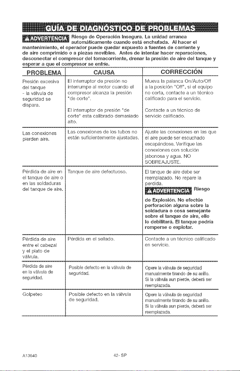
Riesgo de Operaci6n Insegura. La unidad arranca
autom&ticamente cuando est4 enchufada. AI hacer el
mantenimiento, el operador puede quedar expuesto a fuentes de corriente y
de aire comprimJdo o a piezas movibles. Antes de intentar hacer reparaciones,
desconectar el comptesor del tomacorriente, drenar la presi6n de aire del tanque y
esperar a que el compresor se enfrie.
PROBLEMA
Presi6n excesiva
del tanque
- la v_lvula de
seguridad se
dispara.
Las conexiones
pierden aire.
Perdida de aire en
el tanque de aire o
en las soldaduras
del tanque de aire.
P6rdida de aire
entre el cabezal
y el plato de
v_lvula.
P6rdida de aire
en la v41vula de
seguridad.
CAUSA
El interruptor de presi6n no
interrumpe al motor cuando el
compresor alcanza la presi6n
"de corte".
El interruptor de presi6n "de
corte" esta calibrado demasiado
alto.
Las conexiones de los tubos no
est_n suficientemente ajustadas.
Tanque de aire defectuoso.
P6rdida en el sellado.
PosJbledefecto en la v_.lvula de
seguridad.
Posible defecto en la v_lvula
de seguridad.
Golpeteo
CORRECCION
Mueva la palanca On/Auto/Off
a la posici6n "Off", si el equipo
no corta, contacte a un t6cnico
calificado para el servicio.
Contacte a un t6cnico de
servicio calificado.
Ajuste las conexiones en las que
el aire puede set escuchado
escap_ndose. Verifique las
conexiones con soluci6n
jabonosa y agua. NO
SOBREAJUSTE.
El tanque de aire debe ser
reemplazado. No repare la
perdida.
Riesgo
de Explosi6n, No efectQe
perforaci6n alguna sobre la
soldadura o cosa semejante
sobre el tanque de aire, eHo
Io debiiitar;_. El tanque podr_a
romperse o explotar.
Contacte a un t6cnico calificado
en servicio.
Opere la v_lvula de seguridad
manualmente tirando de su anil[o.
Si la valvula aun pierde, debe_aser
reempiazada.
Opere la v_lvula de seguridad
manualmente tirando de su anillo.
Si la v_lvula aun pierde, debera set
reemplazada.
A13640 42-SP
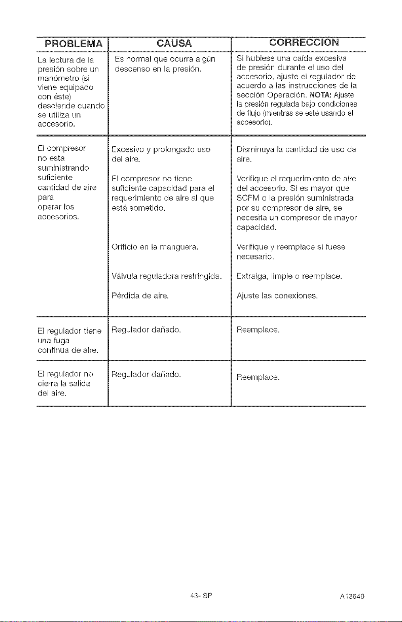
PROBLEMA CORRECCION
La lectura de la
presi6n sobre un
man6metro (si
viene equipado
con _ste)
desciende cuando
se utiliza un
accesorio.
El compresor
no esta
suministrando
suficiente
cantidad de aire
para
operar los
accesorios.
El regulador tiene
una fuga
continua de aire.
El regulador no
cierra la salida
del aire.
CAUSA
Es normal que ocurra alg0n
descenso en la presi6n.
Excesivo y prolongado uso
del aire.
El compresor no tiene
suficiente capacidad para el
requerimiento de aire al que
est_ sometido.
Orificio en la manguera.
Valvula reguladora restringida.
P6rdida de aire.
Regulador daCiado.
Regulador dafiado.
Si hubiese una ca[da excesiva
de presi6n durante el uso del
accesorio, ajuste el regulador de
acuerdo alas instrucciones de la
secci6n Operaci6n. NOTA: Aiuste
la presi6n regulada baio condiciones
de flujo (mientras se est_ usando el
accesorio).
Disminuya la cantidad de uso de
aire.
Verifique el requerimiento de aire
del accesorio. Si es mayor que
SCFM o la presion suministrada
pot su compresor de aire, se
necesita un compresor de mayor
capacidad.
Verifique y reemplace si fuese
necesario.
Extraiga, limpie o reemplace.
Ajuste las conexiones.
Reemplace.
Reemplace.
43-SP A13640
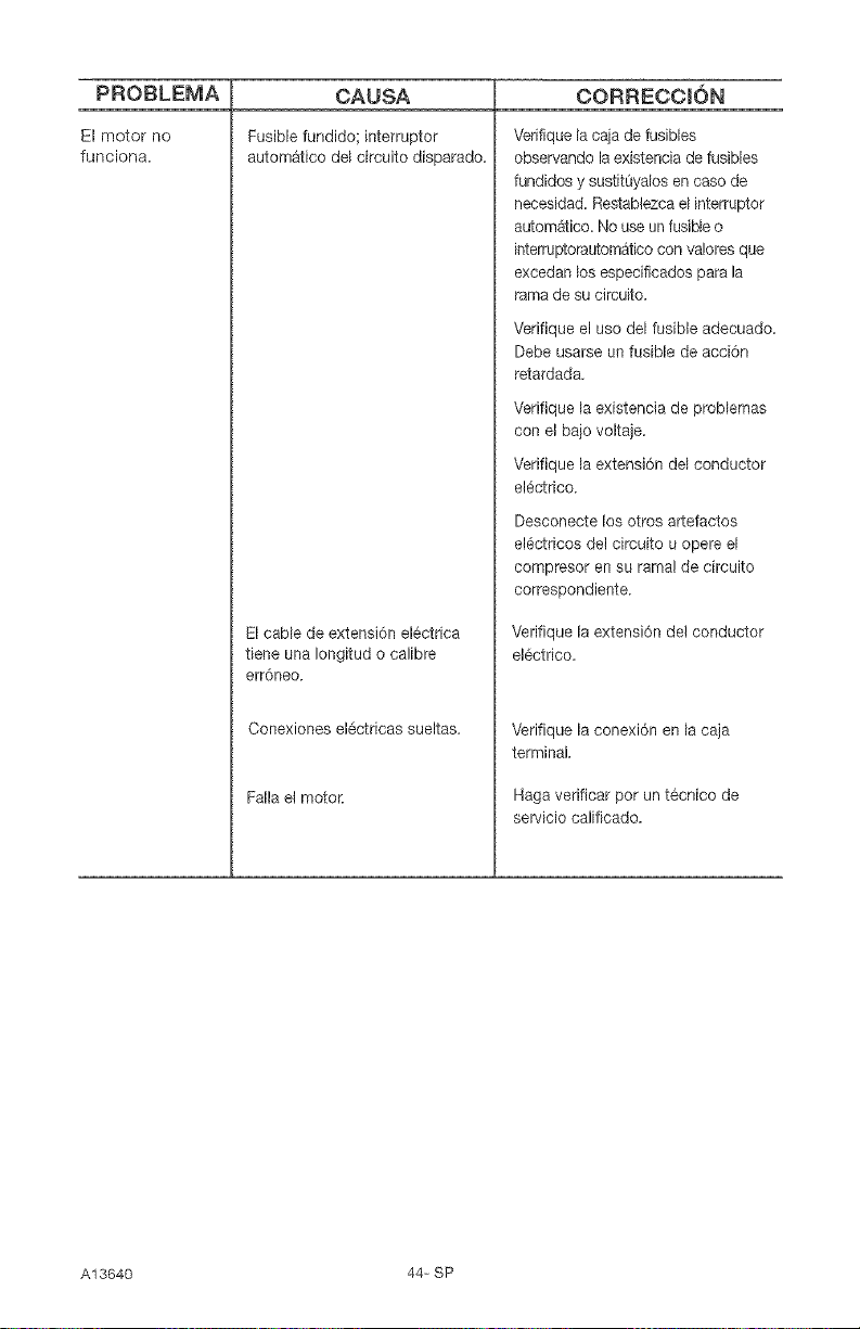
PROBLEMA
El motor no
funciona.
CAUSA
Fusible fundidol interrupter
autom_tico del circuito disparado,
El cable de extension elOctrica
tiene una Iongitud o calibre
err6neo,
Conexiones elOctricas sueltas,
Falla et motor,
CORRECCION
Verifique la ca}a de fusibles
observando la existencia de fusibles
fundidos y sustit_yalos en caso de
necesidad, Restablezcael inter_uptor
automatico. No useun fusibleo
interruptorautom;Jticocon va!ores que
exeedan los especificados para la
rama de su circuito,
Verifique el use del fusible adecuado,
Debe usarse un fusible de aceiOn
retardada.
Verifique la existencia de problemas
con el bajo voltaje,
Verifique la extension del conductor
elOctrico,
Desconecte los otros artefactos
elOctricos del circuito u opere el
compresor en su rama! de circuito
correspondiente,
Verifique la extension del conductor
elOctrico,
Verifique la conexiOn en la caja
terminal,
Haga verificar pot un tecnieo de
servicio calificado,
A13640 44- SP
45-SP A13640
A13640 46-SP
Repair Protection Agreements
Congratulations on making a smart
purchase. Your new Craftsman Crbproduct
is designed and manufactured for years
of dependable operation. But like all
products, it may require repair from time
to time. That's when having a Repair
Protection Agreement can save you
money and aggravation.
Purchase a Repair Protection Agreement
now and protect yourself from unexpected
hassle and expense.
Here's what's included in the Agreement:
r_ Expert service by our 12,000
professional repair specialists
r_ Unlimited service and no charge for
parts and labor on all covered repairs
r_ Product repRacement if your covered
product can't be fixed
r_ Discount of 10% from regular price
of service and service-related parts
not covered by the agreement; also,
10% off regular price of preventive
maintenance check
Fast help by phone - phone support
from a Sears technician on products
requiring in-home repair, plus
convenient repair scheduling
Once you purchase the Agreement, a
simple phone call is all that it takes for you
to schedule service. You can call anytime
day or night, or schedule a service
appointment online.
Sears has over 12,000 professional repair
specialists, who have access to over 4.5
million quality parts and accessories.
That's the kind of professionalism
you can count on to help prolong the
life of your new purchase for years to
come. Purchase your Repair Protection
Agreement today[
Some limitations and excBusions apply.
For prices and additional information
call 1=800=827=66&5,
Sears installation Service
For Sears professional installation of home
appliances, garage door openers, water
heaters, and other major home items, in
the U.S.A. call I=8O0=4=MY=HOME ®
Contratos de Protecci6n para
Reparaciones
Felicitac/ones par hacer una compra
/ntel/gente. Su nueva unidad Craftsman _p esta
diseRada y fabricada para a[ios de operaci6n
confiable; pero come todos los productos
de calidad podrian requirir reparaciones de
vez en cuando. Ahi es cuando el Contrato
de Protecci6n para Reparaciones le puede
ahorrar dinero y molestias=
Compre ahora un Contrato de Proteccid_n
para Reparaciones y protejase contra apuros
y gastos/nesperados.
El contrato incluye Io siguiente:
Servicio Experto per uno de nuestros
12.000 profesionales especializados en
reparaciones=
[_ Servicio ilimitado sin cargos per
repuestos ni mane de obra per todas las
reparaeiones cubiertas,
[_ Reemplazo de la anidad si su unidad
eubierta no puede repararse,
[_ Descuento del 10% en servieios y
repuestos no cubiertos per este eontrato,
Tambien 10% de deseuento del preeio
regular par eualquier inspeeei6n de
mantenimiento preventive,
[_ Asistencia telef6nica r&pida par personal
teenieo de soporte de Sears para las
unidades que requieran repararse en su
domoeilio en horarios eonvenientes
para usted,
Una vez que usted cornpre su Contrato, s61o
necesita hacer una simple Ilamada telef6nica
para programar su servicio. Puede Ilamar
a cualquier hera, en el dia o la noche o
hacerlo per I[nea via internet.
Sears tiene mas de 12.000 profesionales
especializados en reparaciones que tienen
acceso a mas 4,5 railleries de repuestos
y accesorios de calidad. Ese es el tipo de
profesionalismo con el cual usted puede
contar para ayudarle a prologar la vida
Otil de su unidad durante todos los a[ios
per venir, iCompre hey su Contrato de
Protecci6n para Reparaciones!
Se apEican aEgunas limitacionee y
e×clusiones. Para precios e inforrnaci6n
adicionaE, Hame al 1o800-827o6655.
Servicio de Instalacienes de Sears
Para /nstalac/ones profes/onales per Sears
de artefactos para el hogar, come abridores
de puertas de garajes calentadores de agua
y otros artefactos grandes del hogar, en
EE.UU. Ilame al 1-80Oo4oMY-HOME ®
47-SP A13640
Your Home
For repah- in your home -of all major brand appHiances,
Hawn and garden equipment, or heating and cooHing systems,
no matter who made it, no matter who so_d it!
For the repHacement parts, accessories and
owner's manuaHs that you need to do-it-yourseHfi
For Sears professionaH instaHHation of home appHiances
and items Hikegarage door openers and water heaters.
1-800-4-MY-HOIVIE_ Anytime, day or night
(1-800-469-4663) (U.S.A. and Canada)
www,sears,com www,sears,ca
Our Home
For repair of carry-in products Hike vacuums, Hawnequipment,
and eHectronics, caHHor go onqine for the nearest
Sears Parts and Repair Center,
1-800-488-1222 Anytime, day or night (U.S.A. only)
www.sears.com
To purchase a protection agreement (U.S.A.)
or maintenance agreement (Canada) on a product serviced by Sears:
!-800-827-6655 (U.S.A.) !-800-36!-6665 (Canada)
Para pedir servicio de reparaci6n
a domiciHio,y para ordenar piezas:
Au Canada Four service en franqais:
1-800-LE-FOYER Mc
(1-800-533-6937)
www.sears.ca
_) Sears, Roebuck and Co,
TM SM
(<) Registered Trademark / Trademark / Service Mark of Sears, Roebuck and Co.
(<) Marca Registrada / TM Marca de F_brica / SM Marca de Servicio de Sears, Roebuck and Co.
MCMarque de commerce / MD Marque d_pos_e de Sears, Roebuck and Co.
A13640 48- SP