
INSTALLATION GUIDE
PROFESSIONAL
CPV-488, CPV-485GD, CPV-66, CPV-04
GAS RANGETOPS
US CA
2
SAFETY AND WARNINGS
!
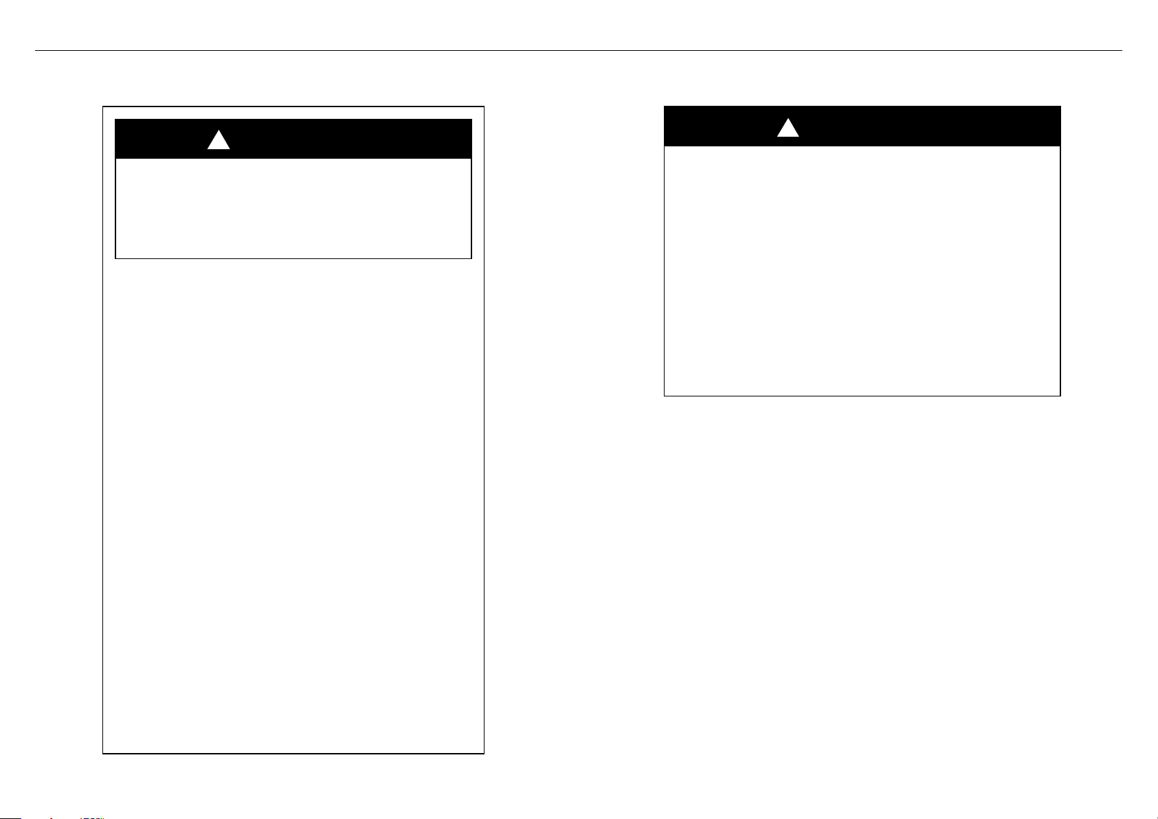
WARNING!
Never operate the top surface cooking
section of this appliance unattended.
• Failure to follow this warning statement
could result in fire, explosion or burn
hazard that could cause property damage,
personal injury or death.
• If a fire should occur, keep away from the
appliance and immediately call your fire
department.
Do not attempt to extinguish
an oil/grease fire with water
!
WARNING!
If the information in this guide is not
followed exactly, a fire or explosion
may result causing property damage,
personal injury or death.
Do not store or use gasoline or other
flammable vapors and liquids in the
vicinity of this or any other appliance.
NEVER use this appliance as a space
heater to heat or warm the room. Doing
so may result in carbon monoxide
poisoning and overheating of the
appliance.
Installation and service must be
performed by a qualified installer,
service agency or the gas supplier.
WHAT TO DO IF YOU SMELL GAS
• Do not try to light any appliance.
• Do not touch any electrical switch.
• Do not use any phone in your
building.
• Immediately call your gas supplier
from a neighbor’s phone.
• Follow the gas supplier’s instructions.
• If you cannot reach your gas supplier,
call the fire department.
3
SAFETY AND WARNINGS
!
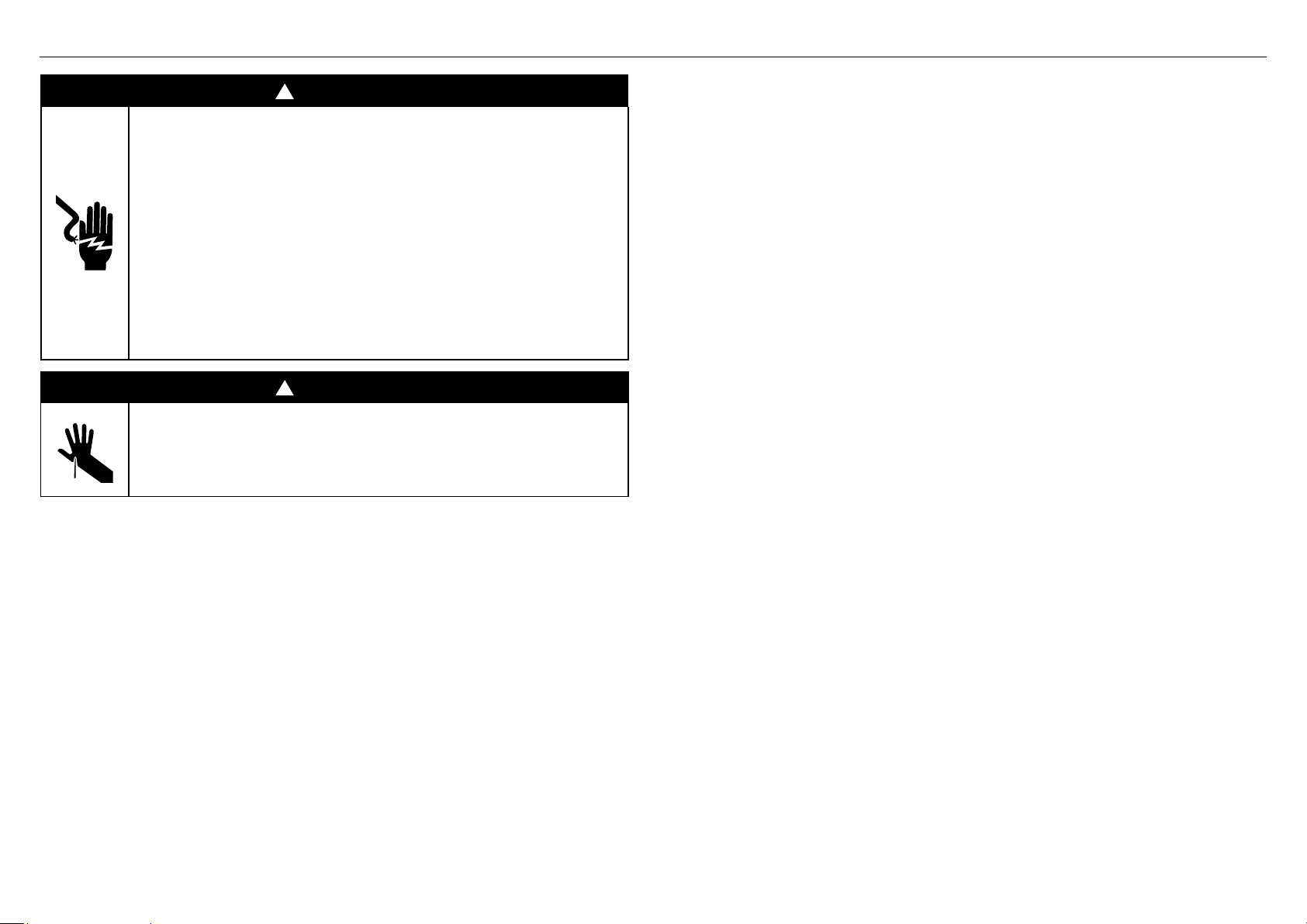
WARNING!
Electric Shock Hazard
Failure to follow this advice may result in
electrical shock or death.
• Before carrying out any work on the electrical
section of the appliance, it must be disconnected
from the mains electricitysupply.
• Connection to a good ground wiring system is
absolutely essential and mandatory.
• Alterations to the domestic wiring system must
only be made by a qualified electrician.
!
WARNING!
Cut Hazard
Failure to use caution could result in injury.
• Take care: some edges are sharp.
READ AND SAVE THIS GUIDE
WARNING!
To reduce the risk of fire, injury to persons or damage when using the appliance, follow the
important safety instructions listed below. Read all the guidance before using the appliance.
Servicing
z
Do not repair or replace any part of the appliance unless specifically recommended in
the user guide. All other servicing should be undertaken be a Fisher & Paykel trained and
supported service technician or qualified person.
z
Technicians must disconnect the power supply before servicing this appliance.
z
Please make this information available to the person installing the appliance
z
This appliance must be installed and connected to the mains power supply only by a
suitably qualified person according to these installation instructions and in compliance
with any applicable local building and electricity regulations. Failuretoinstall the
appliance correctly could invalidate any warranty or liability claims.
Gas Requirements
z
Be sure that the unit being installed is set up for the kind of gas being used. The
gasrangetop is shipped from the factory set and adjusted for Natural Gas or LP (propane),
depending on the specific model ordered. Verify that the rangetop is compatible with the
gas at the installation site before proceeding further.
z
Return cooktop to dealer if the unit is not set for site gas supply.
General
z
The appliance must not be installed behind a decorative door in order to avoid
overheating.
z
The cooktop must be grounded.
z
Installation must comply with your local building and electricity regulations.
z
Ensure the installer shows the customer where the gas supply shut-off valve is located.
z
A circuit breaker is recommended.
z
If the power supply cable is damaged, it must be replaced by the manufacturer, itsservice
agent or similarly qualified person in order to avoid a hazard.
z
Do not use adaptors, reducers or branching devices to connect the oven to
themainselectricity supply, as they can cause overheating and burning.
z
Improper installation, adjustment alteration, service or maintenance can cause property
damage, injury or death. Read the installation, operating and maintenance instructions
thoroughly before using, installing or servicing this appliance.
z
DO NOT obstruct the flow of combustion or ventilation air to the appliance.
Besureafresh air supply is available.
z
Check local building codes for the proper method of cooktop installation. Local codes
vary. Installation, electrical connections, and grounding must comply with all applicable
codes. In the absence of local codes, the cooktop should be installed in accordance with
the latest edition of National Fuel Gas Code ANSI Z223.1 and National Electrical Code
ANSI / NFPA 70.
z
The cooktops are tested in accordance with ANSI Z21.1 Standard for Household Cooking
Gas Appliances. These cooktops must be installed in conjunction with a suitable overhead
vent hood. (See ventilation requirements). Due to the high heat capacity of this unit,
particular attention should be paid to the hood and duct work installation to ensure it
meets local building codes. To eliminate risk of burns or fire by reaching over heated
surface units, cabinet storage located above the surface units should be avoided.
z
In Canada: Installation must be in accordance with the current CSA C22.1 Canadian
Electrical Codes Part 1 and/or local codes. Installation must be in accordance with
the current CAN/CGA B149.1 & 2 Gas Installation codes and/or local codes. Electrical
installation must be in accordance with the current CSA C22.1 Canadian Electrical Codes
Part 1 and/or local codes.
4
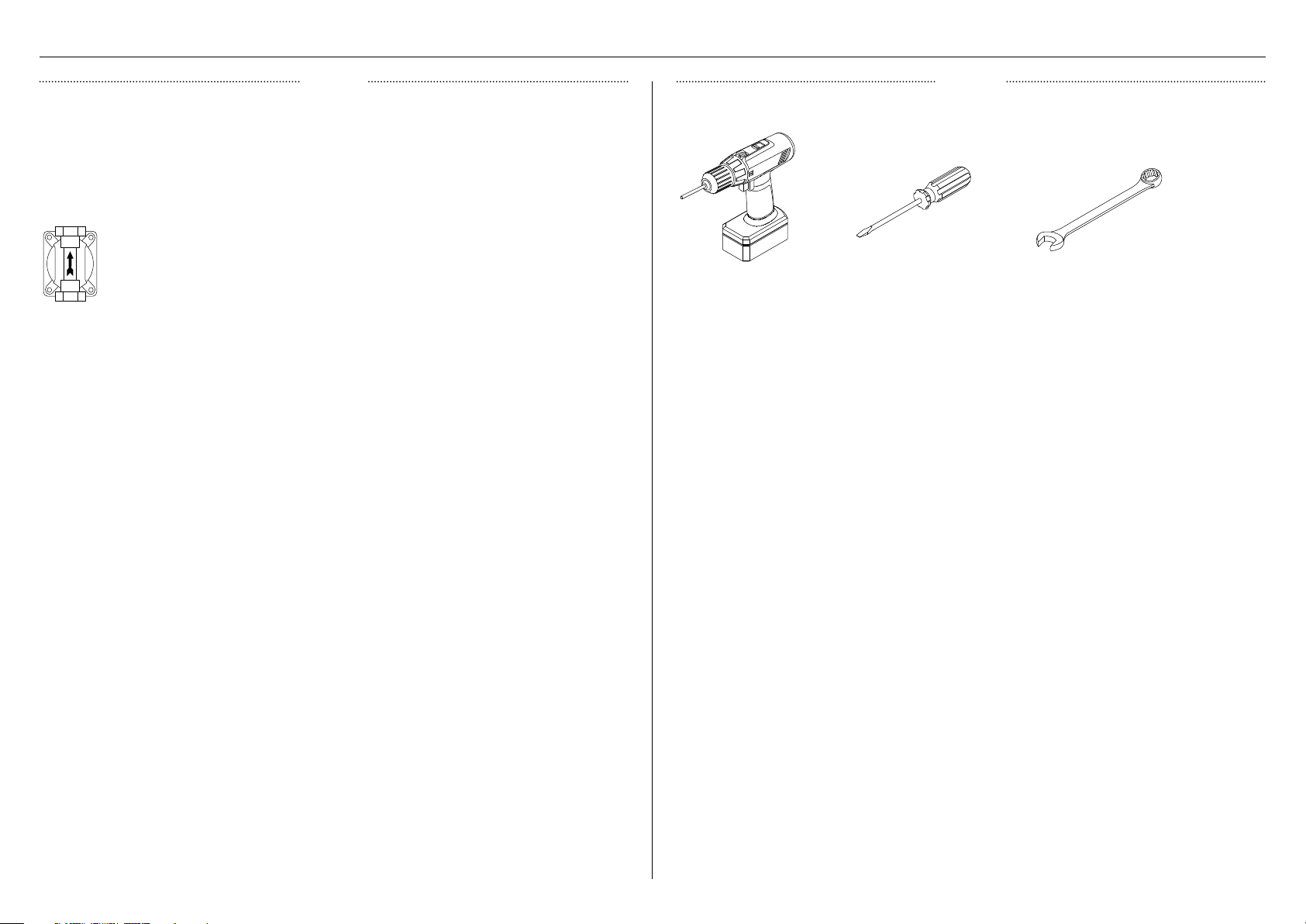
COMPONENTS REQUIRED
PARTS
TOOLS
z
Keep all packing materials until the unit has been inspected.
z
Inspect the product to ensure there is no shipping damage. If any damage is detected
contact the dealer or retailer you bought the product from to report the damage.
z
Fisher & Paykel is not responsible for shipping damage.
Regulator (1)
Powered driver Flat-head screw driver 15/16" spanner (2)
Supplied
Not supplied
5
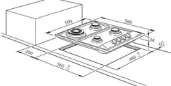
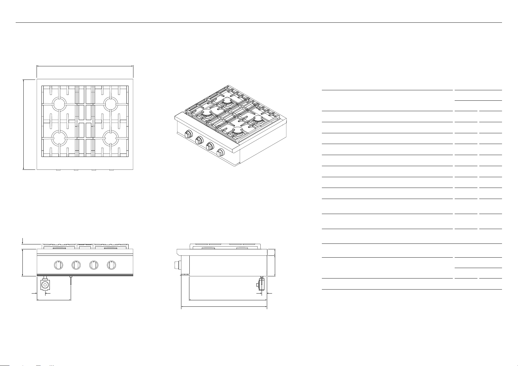
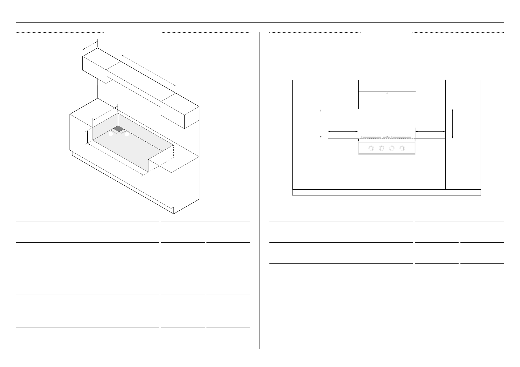
PRODUCT DIMENSIONS 30" MODELS
PLAN
FRONT PROFILE
ISOMETRIC
PRODUCT DIMENSIONS
30" MODELS
IN MM
A Overall height (excluding grates) 8 3/8 213
B Overall width 29 7/8 759
C Overall depth (excluding dials) 28 1/8 714
D Height of chassis 6 3/8 162
E Depth of chassis 24 3/16 614
F Height above countertop 2 51
G Depth from chassis to front of control panel 26 11/16 677
H Height above countertop to top of grates 1 9/16 40
I Distance from left edge of chassis to center line
of gas inlet
2 3/4 70
J Distance from left edge of chassis to center line
of power cord
10 1/2 267
K Distance from rear of chassis to center line of
gas/power
1 5/8 42
PRODUCT WEIGHT
30" MODELS
LB KG
Weight of product (excluding packaging) 121 55
A
I k
j
C
f
E
G
D
H
B
Dimensions may vary by ± 2 mm
CPV3 304 model illustrated
6
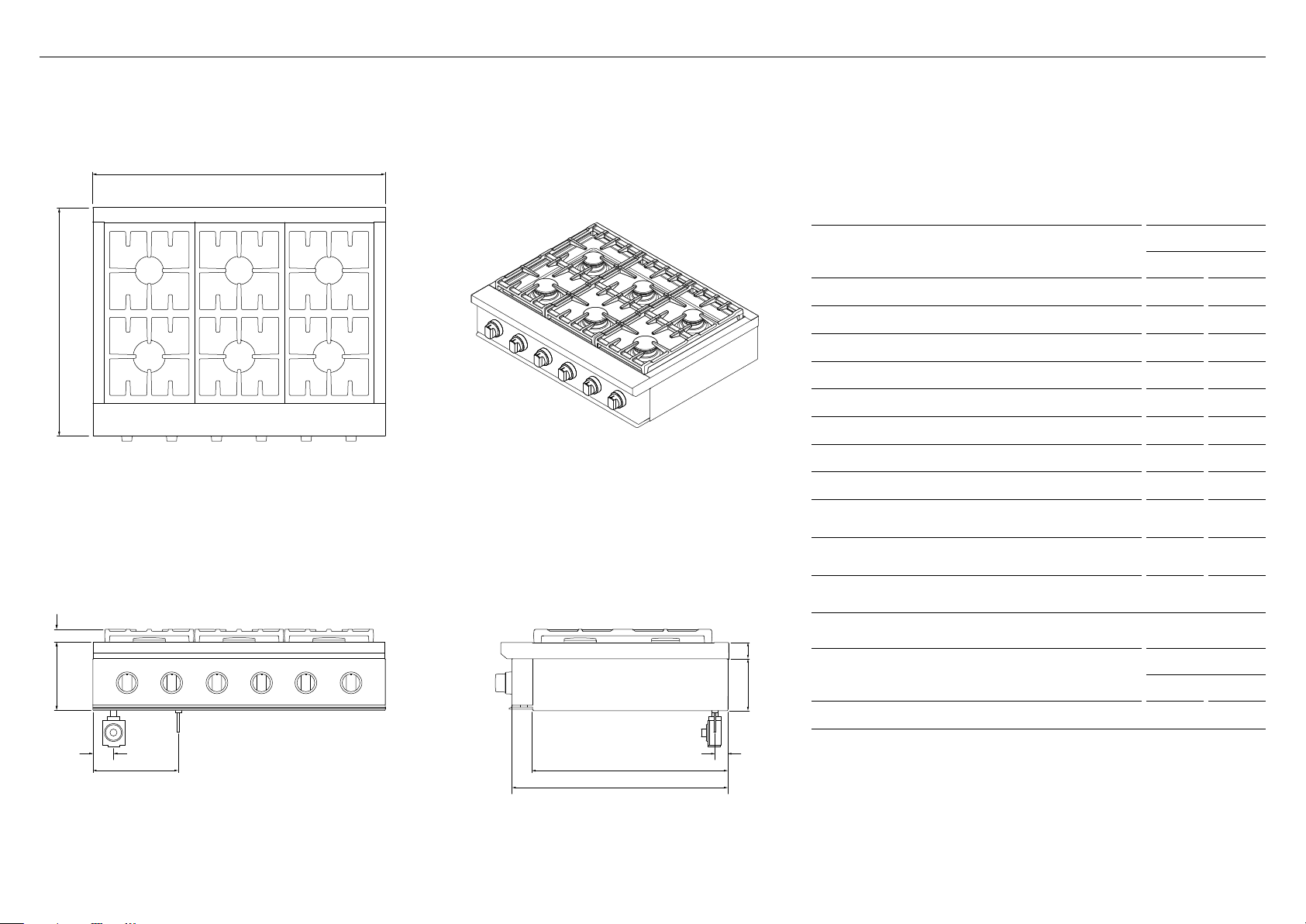
PRODUCT DIMENSIONS 36" MODELS
PRODUCT DIMENSIONS
36" MODELS
IN MM
A Overall height (excluding grates) 8 3/8 213
B Overall width 3 5 7/ 8 911
C Overall depth (excluding dials) 28 1/8 714
D Height of chassis 6 3/8 162
E Depth of chassis 24 3/16 614
F Height above countertop 2 51
G Depth from chassis to front of control panel 26 11/16 677
H Height above countertop to top of grates 1 9/16 40
I Distance from left edge of chassis to center line
of gas inlet
2 3/4 70
J Distance from left edge of chassis to center line
of power cord
10 1/2 267
K Distance from rear of chassis to center line of
gas/power
1 5/8 42
PRODUCT WEIGHT
36" MODELS
LB KG
Weight of product (excluding packaging) 141 64
PLAN ISOMETRIC
A
C
H
B
Dimensions may vary by ± 2 mm
CPV3 365 model illustrated
f
D
FRONT PROFILE
I
k
j
E
G

7
PRODUCT DIMENSIONS 48" MODELS
PRODUCT DIMENSIONS
48" MODELS
IN MM
A Overall height (excluding grates) 8 3/8 213
B Overall width 47 7/8 1216
C Overall depth (excluding dials) 28 1/8 714
D Height of chassis 6 3/8 162
E Depth of chassis 24 3/16 614
F Height above countertop 2 51
G Depth from chassis to front of control panel 26 11/16 677
H Height above countertop to top of grates 1 9/16 40
I Distance from left edge of chassis to center line
of gas inlet
3 1/8 80
J Distance from left edge of chassis to center line
of power cord
10 1/2 267
K Distance from rear of chassis to center line of
gas/power
1 5/8 42
PRODUCT WEIGHT
48" MODELS
LB KG
Weight of product (excluding packaging) 187 - 198 85 - 90
PLAN ISOMETRIC
A
C
H
B
Dimensions may vary by ± 2 mm
CPV3 485GD model illustrated
f
D
FRONT PROFILE
I k
j
E
G
8
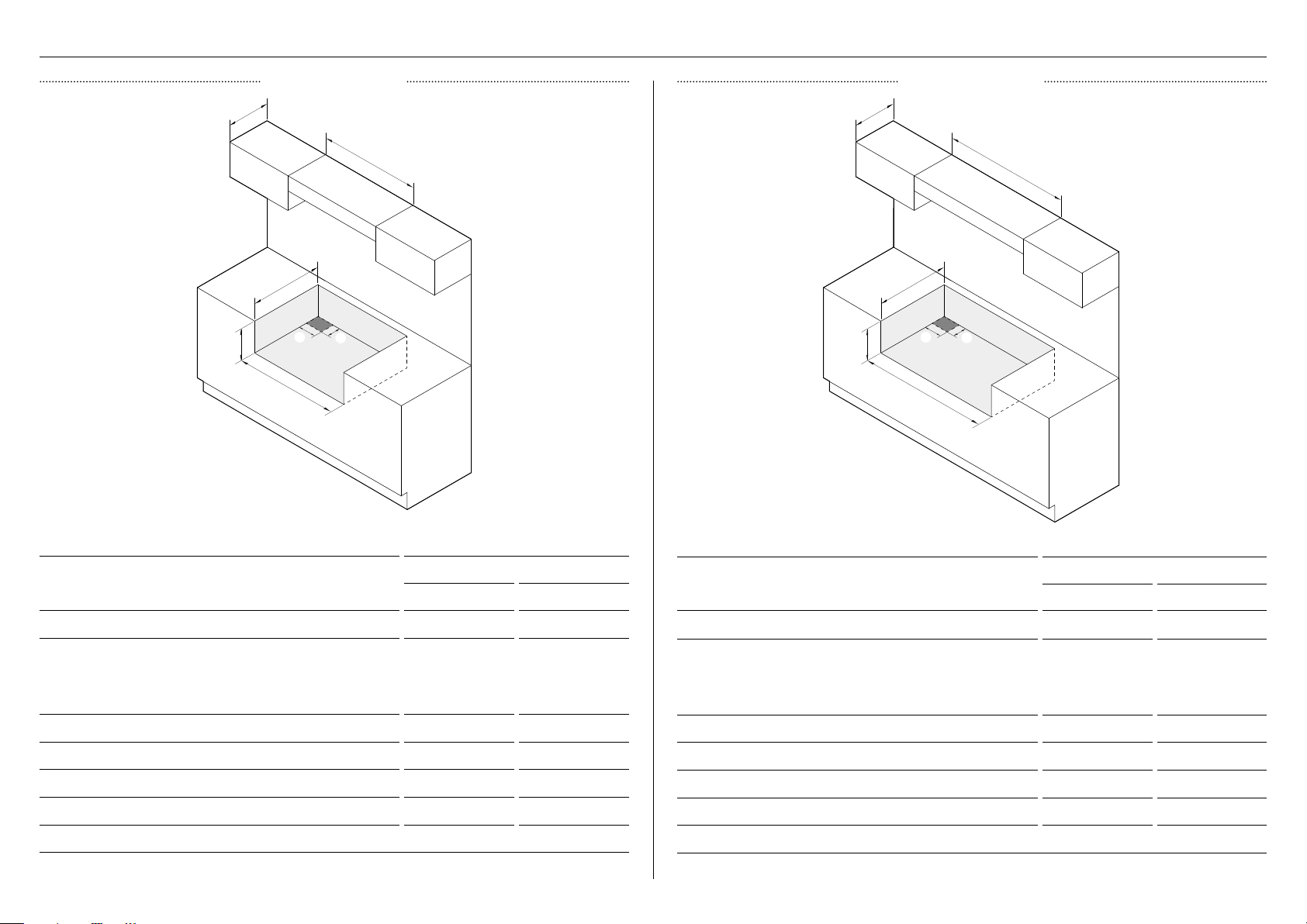
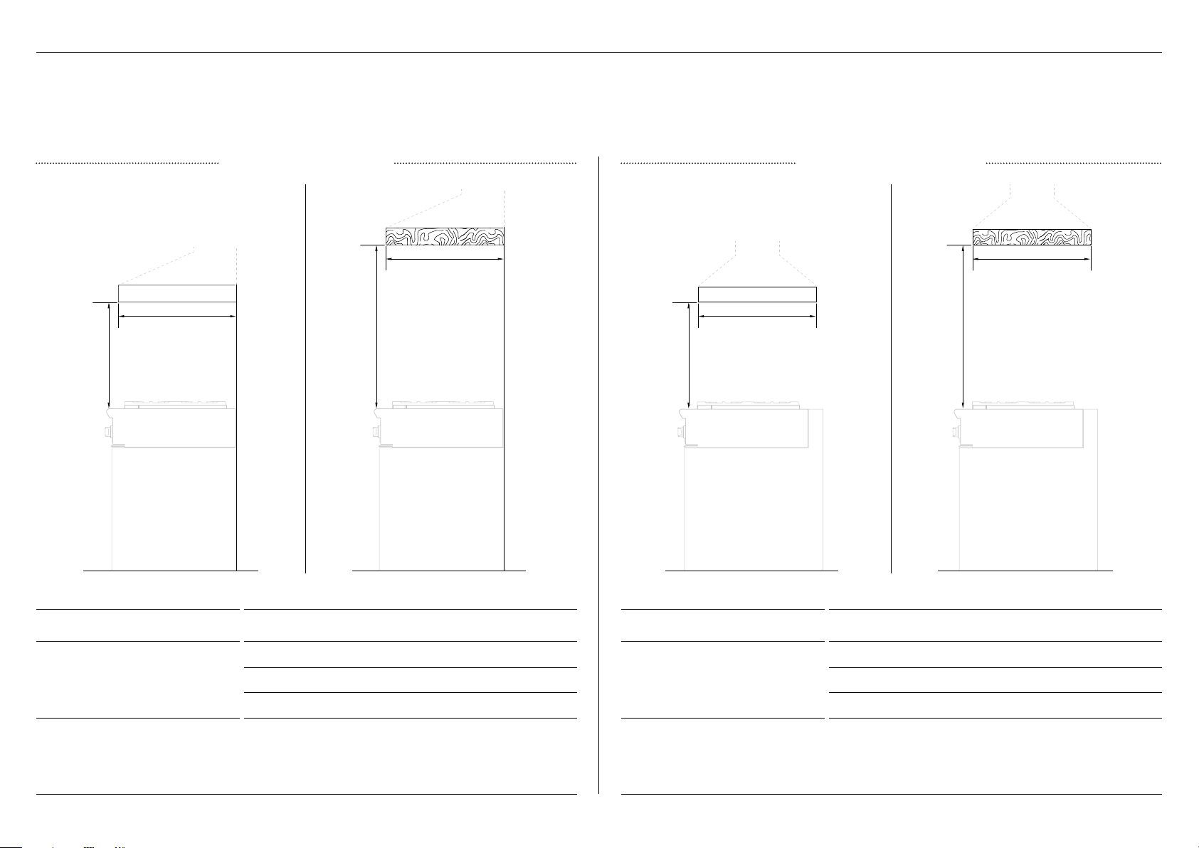
CABINETRY DIMENSIONS
30" CABINETRY
36" CABINETRY
CABINETRY DIMENSIONS
30" MODELS
INCHES MM
A Height 8 203
B Depth
z
Flush with counter 26 5/8 677
z
Projecting control panel 24 3/16 614
C Width 30 762
D Max. depth of overhead cabinetry 13 330
E Min. width of ventilation hood required 30 762
F Width of gas inlet and power cord cut-out 12 305
G Depth of gas inlet and power cord cut-out 8 7/16 215
CABINETRY DIMENSIONS
36" MODELS
INCHES MM
A Max. height 8 203
B Depth
z
Flush with counter 26 5/8 677
z
Projecting control panel 24 3/16 614
C Width 36 915
D Max. depth of overhead cabinetry 13 330
E Min. width of ventilation hood required 36 914
F Width of gas inlet and power cord cut-out 12 305
G Depth of gas inlet and power cord cut-out 8 7/16 215
D D
E
E
We recommend mounting the regulator at the cooktop and using Flex gas line. Refer to page 12 for detailsWe recommend mounting the regulator at the cooktop and using Flex gas line. Refer to page 12 for details
B B
C
C
A A
f
g
f
g
9
CABINETRY DIMENSIONS
48" CABINETRY
CLEARANCES
CLEARANCE DIMENSIONS
ALL MODELS
INCHES MM
A Min. distance from side of rangetop to nearest:
z
vertical combustible surface 12 305
B Min. distance from cook surface to overhead:
z
combustible surface 54 1372
z
combustible covering for ventilation hood 36 914
z
non-combustible surface 30 762
C Min. distance between countertop and cabinet 18 457
D
E
C
B
A A
C
Non-combustible surfaces: as defined in ‘National Fuel Gas Code’ (ANSI Z223.1, Current Edition). Clearances from non-
combustible materials are not part of the ANSI Z21.1 scope and are not certified by UL. Clearances of less than 6" (152mm) must
be approved by the local codes and/or by the local authority having jurisdiction.We recommend mounting the regulator at the cooktop and using Flex gas line. Refer to page 12 for details
The below clearances apply to both wall and island installations for all models.
Ensure the cook surface sits flush or above the adjacent countertop and any openings behind
or under the rangetop are sealed. Flow of combustion and ventilation air must not be obstructed.
Ensure the cooktop is adequately supported from the bottom.
CABINETRY DIMENSIONS
30" MODELS
INCHES MM
A Max. height 8 203
B Depth
z
Flush with counter 26 5/8 677
z
Projecting control panel 24 3/16 614
C Width 48 1219
D Max. depth of overhead cabinetry 13 330
E Min. width of ventilation hood required 30 762
F Width of gas inlet and power cord cut-out 12 305
G Depth of gas inlet and power cord cut-out 8 7/16 215
B
C
A
f
g
10
VENTILATION REQUIREMENTS
WALL INSTALLATION
ISLAND INSTALLATION
VENTILATION UNIT WALL INSTALLATION RECOMMENDATIONS
Hood
A min. 30" (762mm) max. 42 (762mm)
B min. 36" (914mm) max. 42 (762mm)
C min. 19" (480mm)
Blower
30" Rangetop min. 550 CFM
36" Rangetop min. 550 CFM
48" Rangetop min. 1100 CFM
VENTILATION UNIT ISLAND INSTALLATION RECOMMENDATIONS
Hood
A min. 30" (762mm) max. 42 (762mm)
B min. 36" (914mm) max. 42 (762mm)
C min. 19" (480mm)
Blower
30" Rangetop min. 550 CFM
36" Rangetop min. 550 CFM
48" Rangetop min. 1100 CFM
Non-combustible Non-combustibleCombustible Combustible
z
Ventilation hoods and blowers are designed for use with single wall ducting, however some local building codes or inspectors may require double wall ducting and/or a damper. Consultlocal
building codes and/or agencies, before installing to ensure local requirements are met. Semi-rigid ducting is recommended for maximum effectiveness.
z
Hood blower speeds should be variable to reduce noise and loss of household air.
z
Due to a high volume of ventilation air, a source of make-up air (outside replacement air) is recommended. This is particularly important for tightly sealed and insulated homes. A reputable
heating and ventilating contractor should be consulted.
C c
C c
A A
B b
11
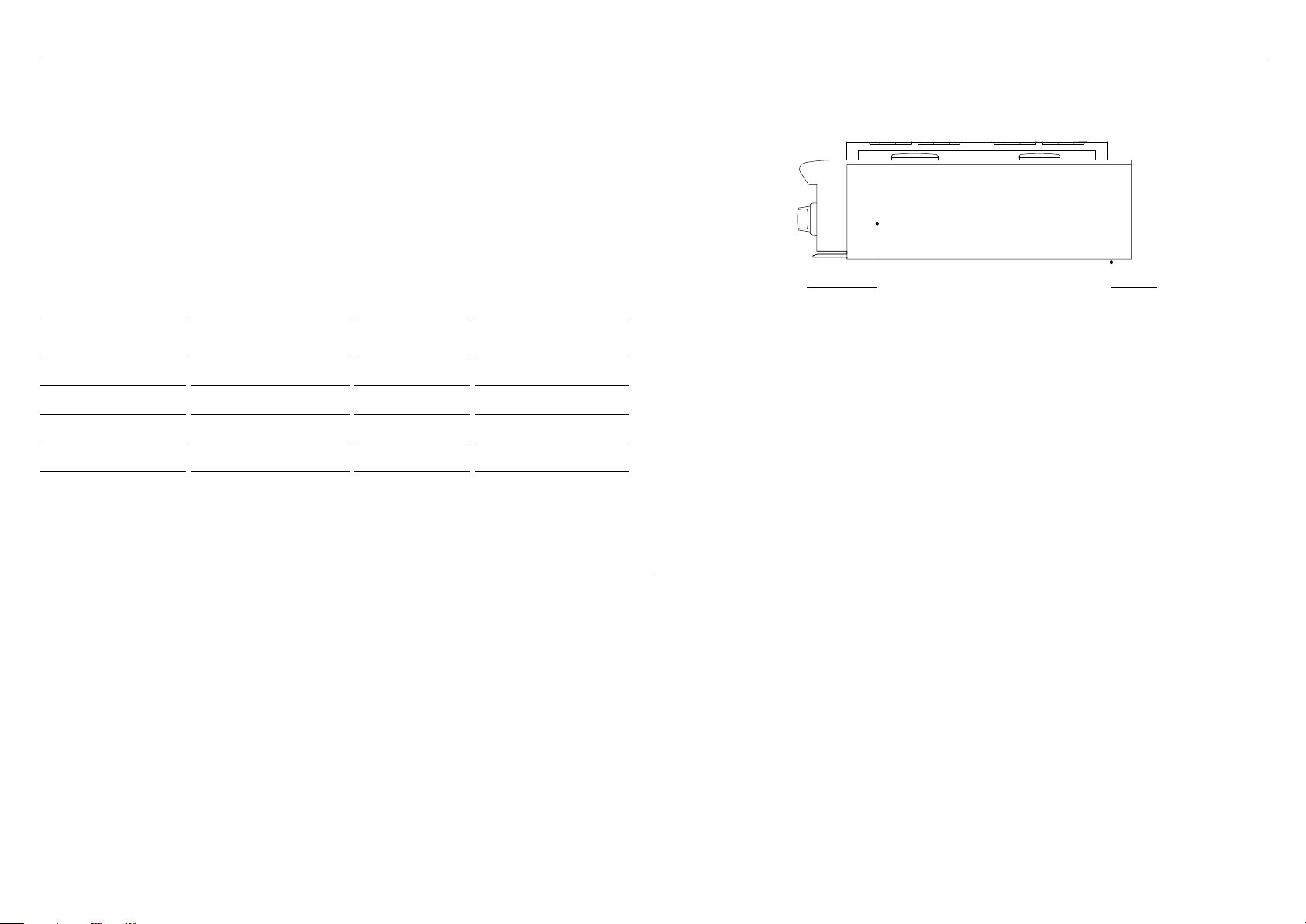
ELECTRICAL REQUIREMENTS
z
This cooktop must be grounded.
z
Always disconnect electric supply cord from the wall outlet or service disconnect before
servicing this appliance.
z
Observe all governing codes and ordinances when grounding, in absence of which, observe
National Electrical Code ANSI / NFPA No. 70.
MODEL VOLTAGE MAX CURRENT MAX POWER
CPV3-304 120 V 0.5 A 60 W
CPV3-366 120 V 0.5 A 60 W
CPV3-485GD 120 V 7 A 840 W
CPV3-488 120 V 0.5 A 60 W
The electrical supply must be a correctly polarized, grounded 120 V AC, 60 Hz, single phase
circuit suitable for the maximum current draw of the model, as detailed in the table below.
Please verify your model’s current draw by checking the rating label on the rangetop.
Required grounding method
This appliance is factory equipped with a power supply cord with a three-prong grounding
plug (with polarized parallel blades). It must be plugged into a mating grounding type
receptacle, connected to a correctly polarized 120 Volt circuit. If the circuit does not have a
grounding type receptacle, it is the responsibility and obligation of the installer to have the
existing receptacle changed to a properly grounded and polarized receptacle in accordance
with all applicable local codes and ordinances by a qualified electrician. In the absence of
local codes and ordinances, the receptacle replacement shall be in accordance with the
National Electrical Code.
The third prong should not, under ANY circumstances, be cut or removed.
The rating label
is located on the
right-hand side
of the rangetop,
near the front.
A wiring
diagram label
is attached to
the bottom of
therangetop
12
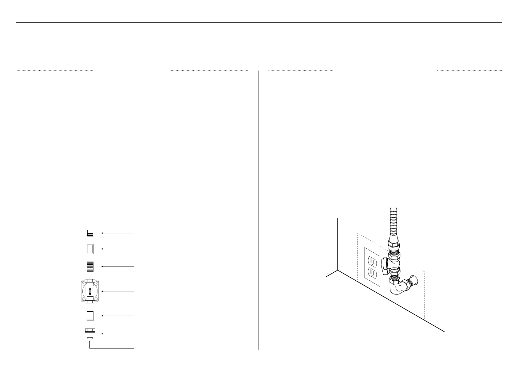
GAS REQUIREMENTS
Connection: 1/2" NPT Minimum 5/8" dia. flex line. Supply pressure: 6" to 9" W.CConnection: 1/2" NPT Minimum 5/8" dia. flex line. Supply Pressure: 11" to 14" W.C.
A regulator is required at the LP source to provide a maximum pressure of 14" W.C. to the
cooktop regulator.
A manual shut-off valve (not supplied) must be installed in an accessible location in the
gas line external to the appliance for the purpose of turning on or shutting off gas to the
appliance. In Massachusetts, such shut-off valves should be approved by the Board of State
Examiners of Plumbers & Gas Fitters. The shut-off valve must be located within 6 feet (1.8
meters) of the appliance.
Ensure the gas supply is turned off at the wall valve before connecting the appliance. The
gas supply connections should be made by a qualified technician and in accordance with
local codes or ordinances. In the absence of a local code, the installation must conform to
the latest edition of National Fuel Gas Code ANSI Z223.1. When within the Commonwealth of
Massachusetts, this appliance must be installed by a licensed plumber or gas fitter.
To prepare the unit for connection to the gas supply
Thread the supplied 1/2" pipe nipple into the elbow on the end of the manifold. The elbow is
located inside the chassis of the unit, on the end of the manifold, facing down. It is accessible
through the square cutout in the left rear corner of the chassis bottom. Connect the outlet of
the regulator to the exposed end of the nipple, connect the flex line from the gas supply to the
inlet side of the regulator.
Fisher & Paykel recommends installing the manual shutoff valve in a location readily accessible
by the customer, so that gas to the appliance can be shut off in an emergency situation.
However, the appliance must not be modified in any way to accommodate such placement.
Pipe sealant must be used on all pipe threads.
The gas supply line must not protrude beyond the back of the appliance.
Ensure the gas supply is turned off at the wall valve before connecting the appliance. Leak-
testing of the appliance shall be conducted according to the manufacturer’s instructions. See
instructions following. When checking the manifold gas pressure, the inlet pressure to the
regulator should be at least 7.0" W.C. for natural gas or 12.0" for LP.
The flex line for the gas supply must be metal and be approved for appliance use by a
certifying agency (CSA, CGA, or UL). Never use a hose made of rubber or other synthetic
material, as the heat may cause the hose to melt and develop leaks.
The arrow on the regulator indicating direction of gas flow should be pointing towards the
unit.
Verify the type of gas supplied to the location. The rangetop is shipped from the factory set up and adjusted for Natural Gas or LP, depending on the specific model ordered. If the rangetop is not
set for the gas supplied at the site, return to the dealer.
Pressure testing at test pressures in excess of 1/2 psig (3.5 kPa.): the rangetop and its individual shut-off valve must be disconnected from the gas supply piping system
Pressure testing at test pressures equal to or less than 1/2 psig (3.5 kPa.): The rangetop must be isolated from the building’s gas supply piping system by closing its individual manual shut-off valve
LP GAS CONNECTION NATURAL GAS CONNECTION
base of product
1/2" coupling
1/2" close nipple
1/2" NPT to 3/8"
flare adapter
to gas supply
1/2" x 5" close nipple
Regulator
13
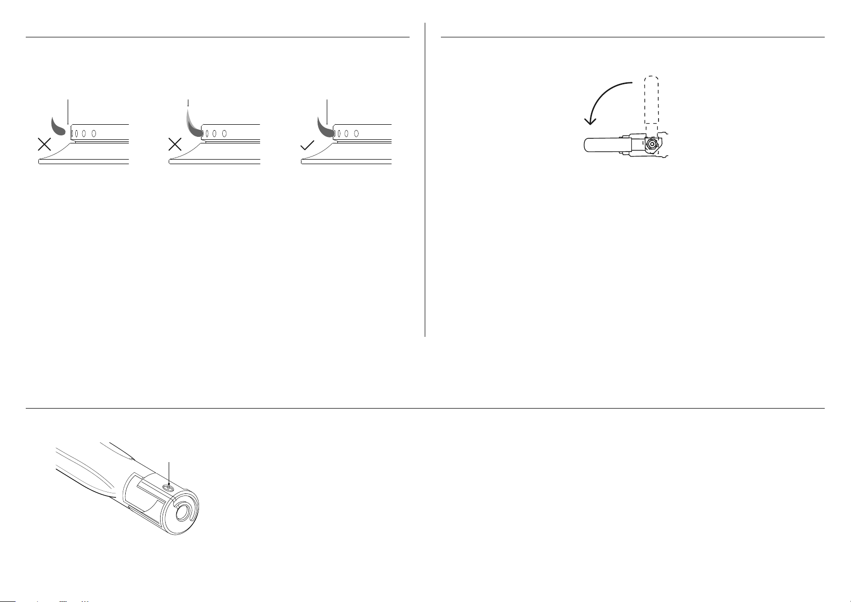
Each valve and air shutter is individually tested and adjusted prior to shipment. Normally adjustment is not required, however,
vibration during transit, gas conversion or variations in the local gas supply may make minor adjustments necessary.
Check for the proper burner flame characteristics and adjust air shutters if necessary. Burner flames should be blue and stable
with no yellow tips, excessive noise or lifting of the flame from the burner. If any of these conditions exist, check that the air
shutter or burner ports are not blocked.
If the condition persists, adjust the air shutter as below:
z
If the flame is too yellow, indicating insufficient air open the shutter to increase air inlet.
z
If the flame is noisy or tends to lift away from the burner, indicating too much air, close the shutter to reduce air.
air shutter
z
Ensure all dials are set to OFF before connecting rangetop to gas supply.
z
After final gas connection is made, turn gas supply on and test all connections in gas supply
piping for gas leaks with a soapy water solution.
z
In order to avoid property damage or serious personal injury, never use a match or open
flame. If a leak is present, tighten joint or unscrew, apply more joint compound, tighten
again and retest connection for leak.
ON
GAS
COOKTOP BURNERS LEAK TESTING
z
To check that the ignition system operates correctly, light each burner by itself, then all
burners in combination.
z
Check for a well-defined blue flame without any yellow tipping.
z
If any abnormality is evident, check that the components of the burner assembly are
located properly.
●
No air shutter adjustment is possible on the rangetop. Correct operation is achieved with
factory installed settings for the correct gas type.
z
When installing the burner port ring, align the two locating pins in the bottom side of the
port ring with the locating notch and center holes on the top side of the simmer ring, and
make sure these are properly engaged.
z
Incorrect installation may produce a potentially dangerous flame and result in poor
burner performance.
z
If proper operation cannot be obtained, contact Customer Care or your nearest
Fisher&Paykel Authorized Service Center.
z
The rangetop must not be used until proper operation has been achieved.
GRILL AND GRIDDLE BURNERS (SOME MODELS ONLY)
lifting off stable blue flameyellow tip

14
TO BE COMPLETED BY THE INSTALLER
Complete and keep for safe reference:
Model
Serial no.
Purchase date
Purchaser
Dealer address
Installer’s name
Installer’s signature
Installation company
Installation date
GENERAL
Specified clearance maintained.
Backguard installed if clearance to combustibles behind unit is less than 6" (152mm).
Unit is level–front to back and side to side.
Griddle (if equiped) and burner pan supports are level and does not rock.
All packaging materials have been removed.
Oven door hinges seated and door opens and closes properly.
Dials turn correctly and freely.
Burners light satisfactorily, both individually and with other burners operating.
Flame adjustments made if required.
FINAL CHECKLIST
GAS
Connection: 1/2 NPT with a minimum 5/8" diameter flex line. Site gas supply is
compatible with cooktop model, and sufficient pressure is available
The pressure regulator which is connected to the manifold is set for 5.0" W.C. for natural
gas or 10.0" W.C. for LP.
anual gas shut-off valve installed in an accessible location.
Unit tested and free of gas leaks.
ELECTRICAL
Receptacle with correctly rated over-current protection is provided for service
cordconnection.
Adequate ground connection.


592189A 05.20
FISHERPAYKEL.COM
© Fisher & Paykel Appliances 2020. All rights reserved.
The models shown in this guide may not be available in all markets
and are subject to change at any time.
The product specifications in this guide apply to the specific products and
models described at the date of issue. Under our policy of continuous product
improvement, these specifications may change at any time.
For current details about model and specification availability in your country,
please go to our website or contact your local Fisher&Paykel dealer.