Loading ...
Loading ...
Loading ...

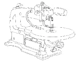
Basic Scroll Saw
Blades
Your new Scroll Saw accepts 5 inch Pin-End blades or 5 inch
Plain-End blades (See Accessories on page 18).
To prevent personal injury always disconnect
the plug from power source before changing
blades or making adjustments.
Removing and Installing
Pin-End Blades
1. Release blade tension by lifting up the Quick Release
Tension Lever (Fig. 7).
2. Open easy access door and loosen the blade clamping
knob on the upper and lower blade holders. Remove blade
from the upper and lower blade holders by pulling forward on
blade and then lifting the blade through the access hole in
the table. Slight downward pressure against the upper hold-
er may be helpful when removing blade from upper holder.
3. Look at the blade holders closely and notice the blade
slots and pin recesses in the blade holders.
NOTE: In order to cut, and avoid uncontrollable lifting of the
workpiece, the teeth of the blade used on the Scroll Saw
should always point downward as shown in (Fig. 6) when
installed.
4. Install the blade by inserting one end of the blade through
the access hole in the table and hook the blade pin in the pin
recess in the lower blade holder. Slide the top blade pin into
the pin recess of the upper blade holder. You may need to
press down lightly on the upper blade holder to install the
blade.
5. Check to see that the pins are properly located in the blade
holders.
Operations
Removing and Installing
Plain-End Blades
1. Release blade tension by lifting up the Quick Release
Tension Lever (Fig. 7).
2. Open easy access door and loosen the blade clamping
knob on the upper and lower blade holders. Remove blade
from the upper and lower blade holders by pulling forward
on blade and then lifting the blade through the access hole
in the table.
3. Install the blade by inserting one end of the blade through
the access hole in the table and centering the blade in the
blade slot in the upper and lower blade holders. To secure
the blade securely tighten the clamping knob on the upper
and lower holders. If desired, the allen wrench provided can
assist in securely tightening the blade into the upper and
lower blade holders (Fig. 6).
Blade Tension
To tension blade, move Quick ReleaseTension Lever to "down"
position. As the lever is lowered, tension will be applied to the
blade (Fig. 8).
ATTENTION: Moving the lever downward should require mod-
erate, steady pressure only. If heaw pressure is needed, the
blade is too tight. Loosen tension by rotating the Quick Release
Tension Lever counterclockwise 1-2 turns, then reset the ten-
sion lever to the "down" position. If the tension lever is in the
"down" position and the blade is too loose, you can increase
tension by leaving the tension lever "down" and rotating it
clockwise just until you feel the slack in the blade removed.
Then turn the tension lever ONE full turn clockwise. This amount
of blade pressure should do well for most cutting operations
and blades (Fig. 7).
I=[,_1[,I
SLIGHT
PRESSURE
HERE
C_AMP
NOB
___ UPPER BLADE
HOLDER
BLADE _I(
I=[._'_lr4
ABLE TILTED FOR PICTURE CLARITY
When the blade tension has been properly adjusted, you should
be able to lift up the Quick ReleaseTension Lever, remove and
install the blade, lower the lever and return the original blade
tension.
NOTE: It may be necessary to re-adjust the tension lever when
using different types of blades.
LOOSEN TIGHTEN
QUICK RELEASE
TENSION LEVER
LOWER BLADE
HOLDER
I=[_ E=]
CLAMP
KNOB
12.
QUICK RELEASE
TENSION LEVER
Loading ...
Loading ...
Loading ...