Loading ...
Loading ...
Loading ...
WARNING:Do not remove or alter the line cutting
blade assembly. Excessive line length will make the
clutch overheat. This may lead to serious personal
injury or damage to the unit.
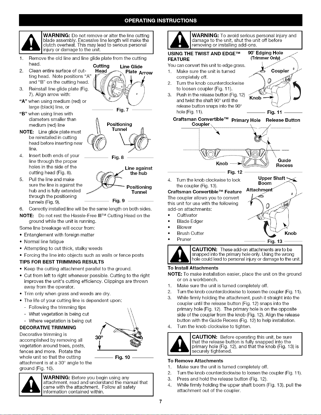
1. Remove the old line and line glide plate from the cutting
head. Cutting Line Glide
2. Clean entire surface of cut- Nead_ Plate Arrow
ting head. Note positions "A" /J_ /_'_/_ ]. j
and "B" on the cutting head. ((I if//_::_}
3. Reinstall line glide plate (Fig. "_J/ t_/_-/_::_J/,_/ I
7). Align arrow with: __,._"A" when using medium (red) or
large (black) line, or
"B" when using lines with
diameters smaller than
medium (red)line
NOTE: Line glide plate must
be reinstalled in cutting
head before inserting new
line.
4. Insert both ends of your
line through the proper
holes in the side of the
cutting head (Fig. 8).
5. Pull the line and make
sure the line is against the
hub and is fully extended
through the positioning
tunnels (Fig. 9).
Fig. 7
Positioning
Tunnel
Fig. 8
Fig. 9
ainst
the hub
Positioning
Tunnel
6. Correctly installed line will be the same length on both sides.
NOTE: Do not rest the Hassle-Free IIITM Cutting Head on the
ground while the unit is running.
Some line breakage will occur from:
• Entanglement with foreign matter
• Normal line fatigue
• Attempting to cut thick, stalky weeds
• Forcing the line into objects such as walls or fence posts
TIPS FOR BEST TRIMMING RESULTS
• Keep the cutting attachment parallel to the ground.
• Cut from left to right whenever possible. Cutting to the right
improves the unit's cutting efficiency. Clippings are thrown
away from the operator.
• Trim only when grass and weeds are dry.
• The life of your cutting line is dependent upon:
- Following the trimming tips
- What vegetation is being cut \\
- Where vegetation is being cut
DECORATIVE TRIMMING
Decorative trimming is
30 °
accomplished by removing all
J
vegetation around trees, posts,
fences and more. Rotate the
T
whole unit so that the cutting Fig. 10
attachment is at a 30 °angle to the
ground (Fig. 10).
WARNING: Before you begin using any
attachment, read and understand the manual that
came with the attachment. Follow all safety
information contained within.
_L ARNING: To avoid serious personal injury and
damage to the unit, shut the unit off before
removing or installing add-ons.
USING THE TWIST AND EDGE TM 90° Edging Hole
FEATURE (TrimmerOnly)
You can convert this unit to edge grass.
1. Make sure the unit is turned
completely off.
2.
3.
I
Turn the knob counterclockwise
to loosen coupler (Fig. 11).
Push in the release button (Fig. 12) Knob
and twist the shaft 90° until the
release button snaps into the 90°
hole (Fig. 11).
Fig. 11
Craftsman Convertible TM Primary Hole
Release Button
Coupler \ \ _/
////_ \\\ Guide
Knob _ Recess
Fig. 12
Upper Shaft "-_
4. Turn the knob clockwise to lock _._
the coupler (Fig. 13). _M Attachm_ent_ _//B°°m
Craftsman Convertible Feature
The coupler allows you to convert
this unit for use with the following
add-on attachments:
• Cultivator
• Blade Edger
• Blower
• Brush Cutter
• Pruner Fig. 13
CAUTION: These add-on attachments are to be I
snapped into the primary hole only. Using the wrong
hoe cou dead to persona n ury or damage to the un t.
To Install Attachments
NOTE: To make installation easier, place the unit on the ground
or on a workbench.
1. Make sure the unit is turned completely off.
2. Turn the knob counterclockwise to loosen the coupler (Fig. 11).
3. While firmly holding the attachment, push it straight into the
coupler until the release button (Fig. 12) snaps into the
primary hole (Fig. 12). The primary hole is on the opposite
side of the coupler from the knob (Fig. 12). Align the release
button with the Guide Recess (Fig. 12)to help installation.
4. Turn the knob clockwise to tighten.
CAUTION: Before operating this unit, be sure I
that the release button is fully snapped into the
I
primary hole (Fig. 12), and that the knob (Fig. 13) is
securely tightened.
To Remove Attachments
1. Make sure the unit is turned completely off.
2. Turn the knob counterclockwise to loosen the coupler (Fig. 11).
3. Press and hold the release button (Fig. 12).
4. While firmly holding the upper shaft boom (Fig. 13), pull the
attachment out of the coupler.
Loading ...
Loading ...
Loading ...